Embed Size (px)
Citation preview

quantumM A S C H I N E N - G E R M A N Y
© 2
007
GB
Bench drill
B 13B 14B 16B 20 / B20 Vario
Operating manualVersion 1.2.5
Keep for future reference !
Pillar drill
B 25 / B 25 VarioB 32 / B 32 Vario
Illustr. 0-1: B13 B 25
Page 118 / 01 / 2008 Version 1.2.5 B 13 / B14 / B16 / B20 / B25 / B32 Drilling machine
quantumM A S C H I N E N - G E R M A N Y
© 2007
G
Table of contents
1 Safety1.1 Safety warnings (warning notes) .................................................................................. 5
1.1.1 Classification of hazards ............................................................................... 51.1.2 Further ideograms ......................................................................................... 6
1.2 Proper use .................................................................................................................... 61.3 Possible dangers caused by the drilling machine ......................................................... 71.4 Qualification of employees ........................................................................................... 8
1.4.1 Target group .................................................................................................. 81.4.2 Authorized persons ....................................................................................... 8
1.5 User’s position .............................................................................................................. 91.6 Safety devices .............................................................................................................. 9
1.6.1 ON / OFF switch .......................................................................................... 101.6.2 Drilling machine table .................................................................................. 10
1.7 Separating protective devices .................................................................................... 101.7.1 Drill chuck protection ................................................................................... 101.7.2 Protective cover of the pulleys .................................................................... 111.7.3 Prohibition, warning and mandatory labels ................................................. 11
1.8 Safety check ............................................................................................................... 111.9 Personal protective equipment ................................................................................... 111.10 Safety during operation .............................................................................................. 121.11 Safety during maintenance ......................................................................................... 121.12 Use of lifting equipment .............................................................................................. 13
1.12.1 Mechanical maintenance work .................................................................... 131.13 Accident report ........................................................................................................... 131.14 Electric ........................................................................................................................ 13
2 Technical Data2.1 Power connection ....................................................................................................... 142.2 Drilling capacity .......................................................................................................... 142.3 Spindle holding fixture ................................................................................................ 142.4 Drilling machine table ................................................................................................. 142.10 Emissions ................................................................................................................... 152.5 Dimensions ................................................................................................................. 152.6 Working area .............................................................................................................. 152.7 Revolutions ................................................................................................................. 152.8 Environmental conditions ........................................................................................... 152.9 Operating material ...................................................................................................... 15
3 Assembly3.1 Extent of supply .......................................................................................................... 163.2 Transport .................................................................................................................... 163.3 Storage ....................................................................................................................... 173.4 Installation and assemby ............................................................................................ 17
3.4.1 Assembly ..................................................................................................... 173.4.2 Installation ................................................................................................... 203.4.3 Installation drawings .................................................................................... 20
3.5 First use ...................................................................................................................... 213.5.1 Phase inverter for 400V - machines ............................................................ 22
B
Page 2 Drilling machine B 13 / B14 / B16 / B20 / B25 / B32 Version 1.2.5 18 / 01 / 2008
quantumM A S C H I N E N - G E R M A N Y
© 2
007
GB
4 Handling4.1 Safety ......................................................................................................................... 234.2 Control and indicating elements ................................................................................. 23
4.2.1 B 13, B 14 ................................................................................................... 234.2.2 B 16, B 20, B 25, B 32, B20 Vario, B25 Vario, B32 Vario ........................... 244.2.3 Drill depth stop ............................................................................................ 244.2.4 Inclination of the drilling machine table ....................................................... 25
4.3 Speed alternation ....................................................................................................... 264.3.1 Speed table ................................................................................................. 27
4.4 Standard values for speeds with HSS – Eco – twist drill ............................................ 314.5 Drill chuck ................................................................................................................... 32
4.5.1 Gear rim-drill chuck ..................................................................................... 324.5.2 Disassembly of the drill chuck ..................................................................... 32
4.6 Cooling ....................................................................................................................... 324.7 Before starting the working process ........................................................................... 324.8 During the working process ........................................................................................ 33
5 Maintenance5.1 Safety ......................................................................................................................... 35
5.1.1 Preparation ................................................................................................. 355.1.2 Restarting .................................................................................................... 35
5.2 Inspection and maintenance ...................................................................................... 355.3 Repair ......................................................................................................................... 37
6 Ersatzteile - Spare parts B13, B14, B16, B20, B25, B326.1 Ersatzteilzeichnung - Parts drawing B13 / B14 .......................................................... 386.2 Bohrfutterschutz B13, B14 - Drill chuck protection B13, B14 ..................................... 39
6.2.1 Ersatzteilliste - Parts list B13 / B14 ............................................................. 396.3 Ersatzteilzeichnung - Parts drawing B 16 ................................................................... 416.4 Bohrfutterschutz B16 - Drill chuck protection B16 ...................................................... 42
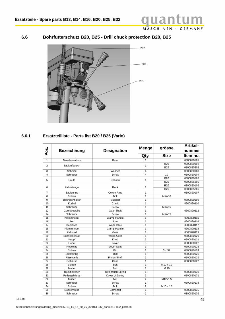
6.4.1 Ersatzteilliste - Parts list B16 ....................................................................... 426.5 Ersatzteilzeichnung - Parts drawing B20 / B25 (Vario) .............................................. 446.6 Bohrfutterschutz B20, B25 - Drill chuck protection B20, B25 ..................................... 45
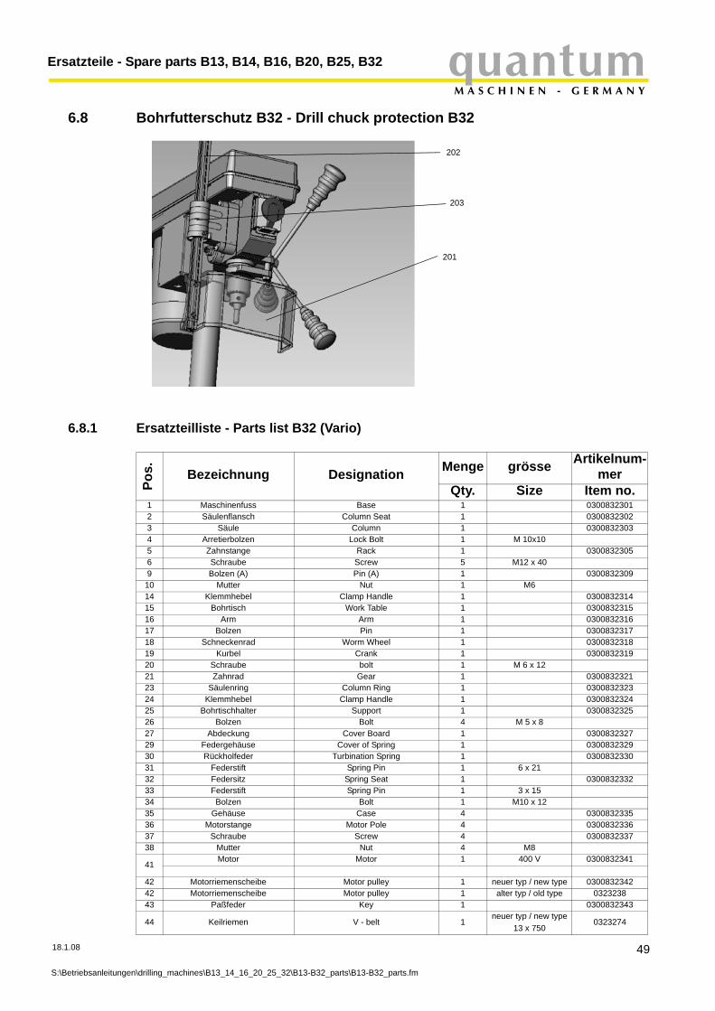
6.6.1 Ersatzteilliste - Parts list B20 / B25 (Vario) ................................................. 456.7 Ersatzteilzeichnung - Parts drawing B32 (Vario) ........................................................ 486.8 Bohrfutterschutz B32 - Drill chuck protection B32 ...................................................... 49
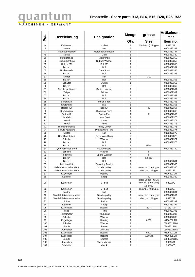
6.8.1 Ersatzteilliste - Parts list B32 (Vario) ........................................................... 496.9 Schaltplan - Wiring diagram B13-B20 (230V) ............................................................ 526.10 Schaltplan - Wiring diagram B20-B32 (400V) ............................................................ 526.11 Schaltplan - Wiring diagram B20Vario-B32Vario (230V) ............................................ 53
7 Malfunctions8 Appendix
8.1 Copyright .................................................................................................................... 568.2 Terminology/Glossary ................................................................................................ 568.3 Warranty ..................................................................................................................... 578.4 Disposal ...................................................................................................................... 578.5 RoHS , 2002/95/CE .................................................................................................... 578.6 Product follow-up ........................................................................................................ 588.7 EC - declaration of conformity .................................................................................... 59
Page 318 / 01 / 2008 Version 1.2.5 B 13 / B14 / B16 / B20 / B25 / B32 Drilling machine
SafetyquantumM A S C H I N E N - G E R M A N Y
© 2007
G
1 Safety
Glossary of symbols
This part of the operating manual
• does explain the meaning and how to use the warning references contained in this operating manual,
• does explain how to use the drilling machine,• highlights the dangers that might arise for you and others if these instructions are not fol-
lowed thoroughly,• informs you on how to prevent dangers.
In addition to this operating manual, please note
• applicable laws and regulations,• legal regulations for preventing an accident,• the prohibition, warning and mandatory signs as well as the warning notes on the drilling
machine.
European standards must be kept during installation, operation, maintenance and repair of thedrilling machine.
If European standards are not applied at the national legislation of the country of destination, thespecific applicable regulations of each country are to be observed.
If necessary, the required measures must be taken to comply with the specific regulations ofeach country before the drilling machine is used for the first time.
Always keep the operating manual close to the drilling machine for further reference.
INFORMATION
If you are not able to solve a problem using this manual, please do not hesitate to contact us forfurther professional advice:
Optimum Maschinen Germany GmbHDr. Robert-Pfleger-Str. 26
D- 96103 Hallstadt
gives further advice
calls on you to get in action
• enumeration
notice
B
Page 4 Drilling machine B 13 / B14 / B16 / B20 / B25 / B32 Version 1.2.5 18 / 01 / 2008
quantumM A S C H I N E N - G E R M A N Y
Safety
© 2
007
GB
1.1 Safety warnings (warning notes)
1.1.1 Classification of hazards
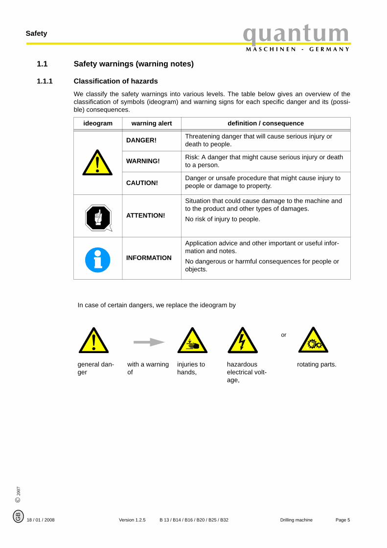
We classify the safety warnings into various levels. The table below gives an overview of theclassification of symbols (ideogram) and warning signs for each specific danger and its (possi-ble) consequences.
ideogram warning alert definition / consequence
DANGER! Threatening danger that will cause serious injury or death to people.
WARNING! Risk: A danger that might cause serious injury or death to a person.
CAUTION!Danger or unsafe procedure that might cause injury to people or damage to property.
ATTENTION!
Situation that could cause damage to the machine and to the product and other types of damages.No risk of injury to people.
INFORMATION
Application advice and other important or useful infor-mation and notes.No dangerous or harmful consequences for people or objects.
In case of certain dangers, we replace the ideogram by
or
general dan-ger
with a warning of
injuries to hands,
hazardous electrical volt-age,
rotating parts.
Page 518 / 01 / 2008 Version 1.2.5 B 13 / B14 / B16 / B20 / B25 / B32 Drilling machine

SafetyquantumM A S C H I N E N - G E R M A N Y
© 2007
G
1.1.2 Further ideograms
1.2 Proper use
WARNING!
In the event of improper use, the drilling-milling machine• will endanger personnel,• will endanger the machine and other material property of the operator,may affect proper operation of the drilling machine.The drilling machine is constructed and designed for the use in non-explosive surrounding. Thedrilling machine is designed and manufactured to be used for drilling cold metals or other non-flammable materials or materials that do not constitute a health hazard by using a rotating cut-ting tool with various chucking grooves.
If the drilling machine is used in any way other than as described above, modified without theauthorisation of Optimum Maschinen GmbH or operated with different process data, then it isbeing used improperly.
We do not take liability for damage caused by improper use.
We would like to stress that any modifications to the construction, or technical or technologicalmodifications that have not been authorised by Optimum Maschinen GmbH will also render theguarantee null and void.
It is also part of proper use that
• the maximum values for the drilling machine are complied with,• the operating manual is observed, • inspection and maintenance instructions are observed.
„Technical Data“ on page 14
Warning of auto-matic start-up!
Activation forbid-den!
Pull the main plug! Use safety glasses!
Use ear protec-tion!
Use protective gloves!
Use protective boots!
Wear a safety suit! Protect the envi-ronment!
Contact address
B
Page 6 Drilling machine B 13 / B14 / B16 / B20 / B25 / B32 Version 1.2.5 18 / 01 / 2008

quantumM A S C H I N E N - G E R M A N Y
Safety
© 2
007
GB
WARNING!
Very serious injury. It is forbidden to make any modifications or alternations to the operating values of the drilling machine! They could endanger employees and cause damage to the drilling machine.
1.3 Possible dangers caused by the drilling machine The drilling machine is state of the art.
Nevertheless, there is a residual risk as the drilling machine operates with
• high revolutions,• rotating parts,• electrical voltage and currents.
We have used construction resources and safety techniques to minimize the health risk to per-sons resulting from these hazards.
If the drilling machine is used and maintained by employees who are poorly qualified, then theremight be a risk resulting from incorrect operation and unsuitable maintenance of the drillingmachine.
INFORMATION
Everyone involved in the assembly, commissioning, operation and maintenance must
• be duly qualified,• strictly follow this operating manual.
Due to improper use
• there is a risk for the employee,• the machine and further property might be endangered,• the function of the drilling machine could be affected.
Always disconnect the drilling machine if cleaning or maintenance work is being carried out.
WARNING!
The drilling machine may only be used with the safety devices activated.Disconnect the drilling machine immediately whenever you detect a failure in the safety devices or when they are not mounted!All additional installations carried out by the operator must incorporate the safety devices prescribed.This is your responsibility being the operator!
„Safety devices“ on page 9
Page 718 / 01 / 2008 Version 1.2.5 B 13 / B14 / B16 / B20 / B25 / B32 Drilling machine

SafetyquantumM A S C H I N E N - G E R M A N Y
© 2007
G
1.4 Qualification of employees
1.4.1 Target group
This manual applies to
• the operators,• the users,• the maintenance staff.
Therefore, the warning notes refer to both operation and maintenance of the drilling machine.
Determine clearly and make a permanent decision in who will be responsible for the differentactivities on the machine (operation, maintenance and repair).
Vague and unclear assignment of responsibilities constitute a safety hazard!
Always disconnect the main plug of the drilling machine. This will prevent it from being used byunauthorized persons.
1.4.2 Authorized persons
WARNING!
Incorrect use and maintenance of the drilling machine constitute a danger for the staff, objects and the environment.Only authorized persons may operate the drilling machine!Persons authorized to operate and maintain should be trained technical staff and instructed by the ones who are working for the operator and for the manufacturer.
The operator must
Obligationsof the opera-
tor
• train the staff,• instruct the staff in regular intervals (at least once a year) on
- all safety standards that apply to the drilling machine,- the operation,- accredited technical guidelines,
• check the knowledge of the staff,• document training / instructions,• require the staff to confirm participation in training / instructions by means of a signature,• check if the staff is aware of safety rules and dangers in the workplace so that they observe
the operating manual.
The user must
Obligationsof the user
• have followed a training on the operation of the drilling machine,• know the function and performance,• before commissioning
- have read and understood the operating manual,- be familiar with all safety devices and regulations.
Furtherrequire-
ments to thequalification
For working on the following machine parts, additional requirements are being applied:
• Electrical parts or operating agents: shall only be performed by an electrician or under the guidance and supervision of an electrician.
Before starting work on electrical parts or operating agents, following measures are to be per-formed in the following order.
B
Page 8 Drilling machine B 13 / B14 / B16 / B20 / B25 / B32 Version 1.2.5 18 / 01 / 2008
quantumM A S C H I N E N - G E R M A N Y
Safety
© 2
007
GB
disconnect all poles
secure against switching on
check dead circuit
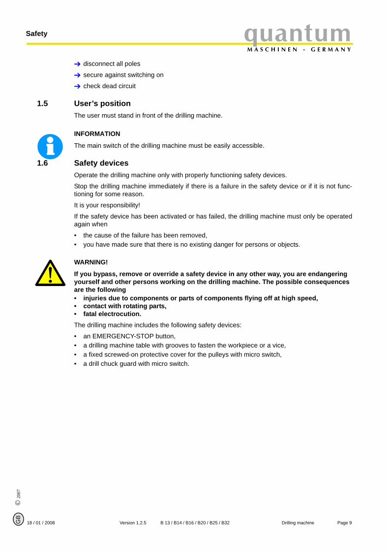
1.5 User’s positionThe user must stand in front of the drilling machine.
INFORMATION
The main switch of the drilling machine must be easily accessible.
1.6 Safety devicesOperate the drilling machine only with properly functioning safety devices.
Stop the drilling machine immediately if there is a failure in the safety device or if it is not func-tioning for some reason.
It is your responsibility!
If the safety device has been activated or has failed, the drilling machine must only be operatedagain when
• the cause of the failure has been removed,• you have made sure that there is no existing danger for persons or objects.
WARNING!
If you bypass, remove or override a safety device in any other way, you are endangering yourself and other persons working on the drilling machine. The possible consequences are the following• injuries due to components or parts of components flying off at high speed, • contact with rotating parts,• fatal electrocution.The drilling machine includes the following safety devices:
• an EMERGENCY-STOP button,• a drilling machine table with grooves to fasten the workpiece or a vice,• a fixed screwed-on protective cover for the pulleys with micro switch,• a drill chuck guard with micro switch.
Page 918 / 01 / 2008 Version 1.2.5 B 13 / B14 / B16 / B20 / B25 / B32 Drilling machine
SafetyquantumM A S C H I N E N - G E R M A N Y
© 2007
G
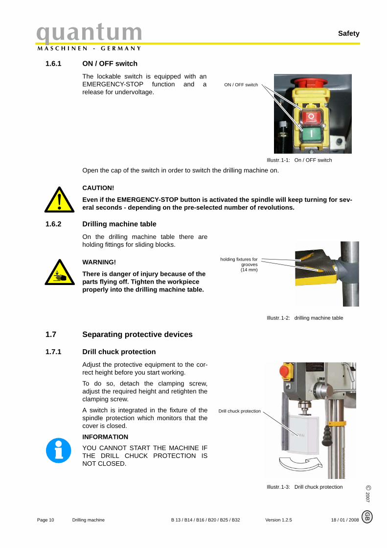
1.6.1 ON / OFF switch
The lockable switch is equipped with anEMERGENCY-STOP function and arelease for undervoltage.
Illustr.1-1: On / OFF switch
Open the cap of the switch in order to switch the drilling machine on.
CAUTION!
Even if the EMERGENCY-STOP button is activated the spindle will keep turning for sev-eral seconds - depending on the pre-selected number of revolutions.
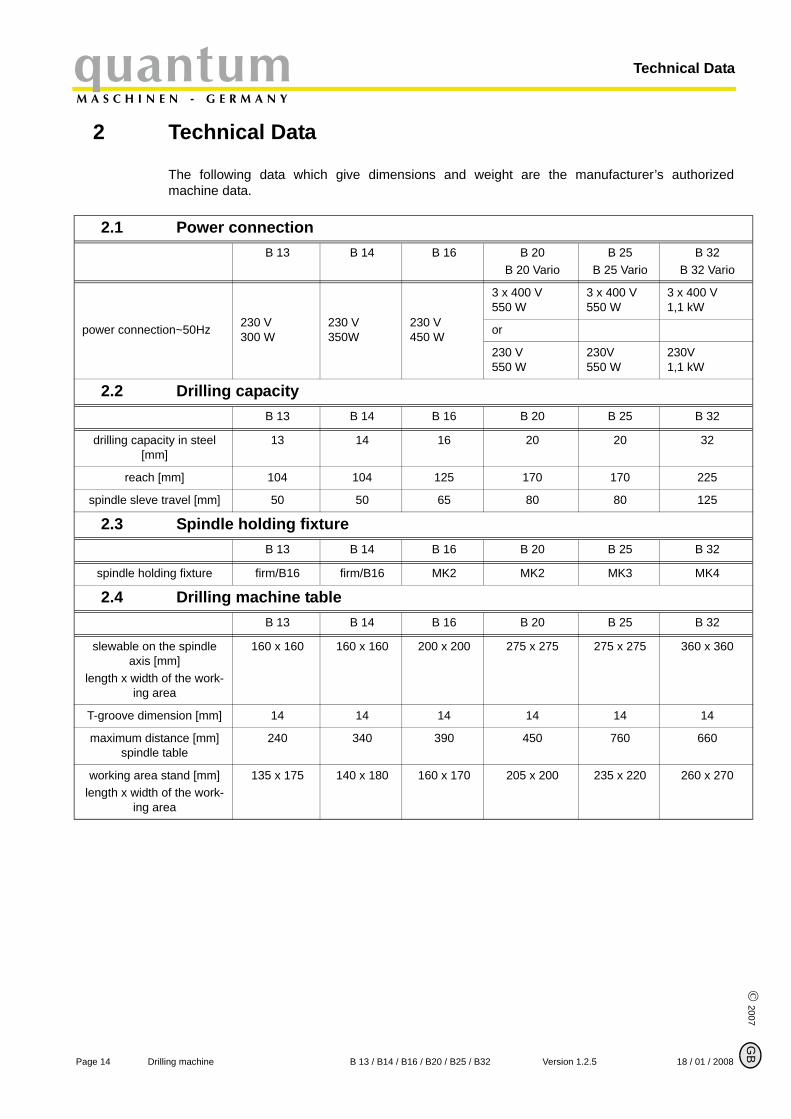
1.6.2 Drilling machine table
On the drilling machine table there areholding fittings for sliding blocks.
WARNING!
There is danger of injury because of the parts flying off. Tighten the workpiece properly into the drilling machine table.
Illustr.1-2: drilling machine table
1.7 Separating protective devices
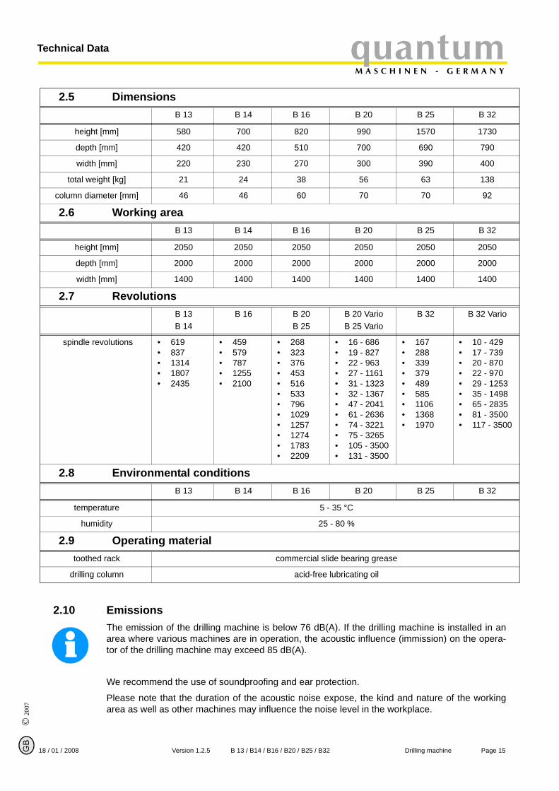
1.7.1 Drill chuck protection
Adjust the protective equipment to the cor-rect height before you start working.
To do so, detach the clamping screw,adjust the required height and retighten theclamping screw.
A switch is integrated in the fixture of thespindle protection which monitors that thecover is closed.
INFORMATIONYOU CANNOT START THE MACHINE IFTHE DRILL CHUCK PROTECTION ISNOT CLOSED.
Illustr.1-3: Drill chuck protection
ON / OFF switch
holding fixtures forgrooves(14 mm)
Drill chuck protection
B
Page 10 Drilling machine B 13 / B14 / B16 / B20 / B25 / B32 Version 1.2.5 18 / 01 / 2008

quantumM A S C H I N E N - G E R M A N Y
Safety
© 2
007
GB
1.7.2 Protective cover of the pulleys
A protective cover for the belt pulleys ismounted on the drilling head. A switch isintegrated in the protective cover whichmonitors that the cover is closed.
INFORMATIONYOU CANNOT START THE MACHINE IFTHE PROTECTIVE COVER IS NOTCLOSED.
Illustr.1-4: protective cover
1.7.3 Prohibition, warning and mandatory labels
INFORMATION
All warning labels must be legible. Check them regularly.
1.8 Safety checkCheck the drilling machine at least once per shift. Inform the person responsible immediately ofany defect or change in the operating function.
Check all safety devices
• at the beginning of each shift (with the machine stopped),• once a week (with the machine in operation),• after every maintenance and repair work.
Check that the prohibition, warning and information labels as well as the markings on the drillingmachine
• are legible (clean them, if necessary),• are complete.
1.9 Personal protective equipmentFor certain work, personal protective equipment is required, such as:
• safety helmet,• protective glasses or face guard,• protective gloves,• safety shoes with steel caps,• ear protection.
Before starting work, make sure that the prescribed personal protective equipment is availableat the workplace.
CAUTION!
Dirty or eventually contaminated personal protective equipment might cause disease.Clean your personal protective equipment • after each use,• regularly once a week.
protective cover
Page 1118 / 01 / 2008 Version 1.2.5 B 13 / B14 / B16 / B20 / B25 / B32 Drilling machine

SafetyquantumM A S C H I N E N - G E R M A N Y
© 2007
G
Personal protective equipment for special work
Protect your face and your eyes: Wear a safety helmet with a face guard for every work, espe-cially for the kind of work where your face and eyes are exposed to hazards.
Use protective gloves when lifting or handling pieces with sharp edges.
Wear safety shoes when fitting, dismanteling or transporting heavy components.
1.10 Safety during operationIn the description of work with and on the drilling machine we highlight the dangers specific tothat work.
WARNING!
Before activating the drilling machine, double check that this will • not endanger other people,• not cause damage to equipment.Avoid unsafe working practice:
• Make sure that your work does not endanger anyone.• The instructions of this manual must be observed strictly during assemby, operation, mainte-
nance and repair.• Do not work on the drilling machine, if your concentration is reduced, for example, because
you are taking medication.• Observe the regulations for the prevention of accidents issued by your association for the
prevention of accidents and safety in the workplace or other inspection authorities.• Inform the inspector of any danger or failure.• Stay at the drilling machine until all rotating parts have come to a halt.• Use the prescribed personal protective equipment. Make sure to wear a well-fitting work suit
and a hainet, if necessary.• Do not use protective gloves when drilling.
1.11 Safety during maintenanceInform the operating staff on time of any repair and maintenance work.
Report all safety-relevant changes or performance details of the drilling machine.Document allchanges, have the operating manual changed accordingly and train the machine operators.
Switching-off and securing the drilling machineUnplug the main switch before starting any maintenance or repair work.
All machine components and hazardous voltages are disconnected.Only the positions which aremarked with the pictogram in the margin are excluded. Attach a warning sign on the machine.
B
Page 12 Drilling machine B 13 / B14 / B16 / B20 / B25 / B32 Version 1.2.5 18 / 01 / 2008

quantumM A S C H I N E N - G E R M A N Y
Safety
© 2
007
GB
1.12 Use of lifting equipment
WARNING!
Use of unstable lifting and load-suspension gear that might break under load can cause very serious injuries or even death.Check the lifting and load-suspension gear on• sufficient load capacity,• perfect condition.Observe the regulations for the prevention of accidents issued by your association for the prevention of occupational accidents and safety in the workplace or other inspection authorities.Fasten the loads properly. Do not walk under lifted loads !
1.12.1 Mechanical maintenance work
Remove all protection and safety devices before starting maintenance work and re-install themonce the work has been completed, such as:
• covers,• safety indications and warning signs,• earth (ground) cables.
If you remove protection or safety devices, refit them immediately after completing the work.Check if they are working properly!
1.13 Accident reportInform your superiors and Optimum Maschinen GmbH immediately in case of accidents, possi-ble sources of danger and any action which almost lead to an accident "near misses".
"Near misses" may have many possible causes.
The sooner they are notified, the faster theses causes can be eliminated.
1.14 ElectricHave the machine and / or the electrical equipment checked regularly, at least every six months.
Eliminate immediately all defects such as loose connections, defective wires, etc.
A second person must be present during work on live components, to disconnect the power incase of an emergency.
Disconnect the drilling machine immediately if there is a malfunction in the power supply!
„Maintenance“ on page 34
Page 1318 / 01 / 2008 Version 1.2.5 B 13 / B14 / B16 / B20 / B25 / B32 Drilling machine
Technical DataquantumM A S C H I N E N - G E R M A N Y
© 2007
G
2 Technical Data
The following data which give dimensions and weight are the manufacturer’s authorizedmachine data.
2.1 Power connectionB 13 B 14 B 16 B 20
B 20 VarioB 25
B 25 VarioB 32
B 32 Vario
power connection~50Hz 230 V300 W
230 V350W
230 V450 W
3 x 400 V550 W
3 x 400 V550 W
3 x 400 V1,1 kW
or
230 V 550 W
230V550 W
230V1,1 kW
2.2 Drilling capacityB 13 B 14 B 16 B 20 B 25 B 32
drilling capacity in steel [mm]
13 14 16 20 20 32
reach [mm] 104 104 125 170 170 225
spindle sleve travel [mm] 50 50 65 80 80 125
2.3 Spindle holding fixtureB 13 B 14 B 16 B 20 B 25 B 32
spindle holding fixture firm/B16 firm/B16 MK2 MK2 MK3 MK4
2.4 Drilling machine tableB 13 B 14 B 16 B 20 B 25 B 32
slewable on the spindle axis [mm]
length x width of the work-ing area
160 x 160 160 x 160 200 x 200 275 x 275 275 x 275 360 x 360
T-groove dimension [mm] 14 14 14 14 14 14
maximum distance [mm]spindle table
240 340 390 450 760 660
working area stand [mm]length x width of the work-
ing area
135 x 175 140 x 180 160 x 170 205 x 200 235 x 220 260 x 270
B
Page 14 Drilling machine B 13 / B14 / B16 / B20 / B25 / B32 Version 1.2.5 18 / 01 / 2008
quantumM A S C H I N E N - G E R M A N Y
Technical Data
© 2
007
GB
2.10 EmissionsThe emission of the drilling machine is below 76 dB(A). If the drilling machine is installed in anarea where various machines are in operation, the acoustic influence (immission) on the opera-tor of the drilling machine may exceed 85 dB(A).
We recommend the use of soundproofing and ear protection.
Please note that the duration of the acoustic noise expose, the kind and nature of the workingarea as well as other machines may influence the noise level in the workplace.
2.5 DimensionsB 13 B 14 B 16 B 20 B 25 B 32
height [mm] 580 700 820 990 1570 1730
depth [mm] 420 420 510 700 690 790
width [mm] 220 230 270 300 390 400
total weight [kg] 21 24 38 56 63 138
column diameter [mm] 46 46 60 70 70 92
2.6 Working areaB 13 B 14 B 16 B 20 B 25 B 32
height [mm] 2050 2050 2050 2050 2050 2050
depth [mm] 2000 2000 2000 2000 2000 2000
width [mm] 1400 1400 1400 1400 1400 1400
2.7 RevolutionsB 13B 14
B 16 B 20B 25
B 20 VarioB 25 Vario
B 32 B 32 Vario
spindle revolutions • 619• 837• 1314• 1807• 2435
• 459• 579• 787• 1255• 2100
• 268• 323• 376• 453• 516• 533• 796• 1029• 1257• 1274• 1783• 2209
• 16 - 686• 19 - 827• 22 - 963• 27 - 1161• 31 - 1323• 32 - 1367• 47 - 2041• 61 - 2636• 74 - 3221• 75 - 3265• 105 - 3500• 131 - 3500
• 167• 288• 339• 379• 489• 585• 1106• 1368• 1970
• 10 - 429• 17 - 739• 20 - 870• 22 - 970• 29 - 1253• 35 - 1498• 65 - 2835• 81 - 3500• 117 - 3500
2.8 Environmental conditionsB 13 B 14 B 16 B 20 B 25 B 32
temperature 5 - 35 °C
humidity 25 - 80 %
2.9 Operating materialtoothed rack commercial slide bearing grease
drilling column acid-free lubricating oil
Page 1518 / 01 / 2008 Version 1.2.5 B 13 / B14 / B16 / B20 / B25 / B32 Drilling machine
AssemblyquantumM A S C H I N E N - G E R M A N Y
© 2007
G
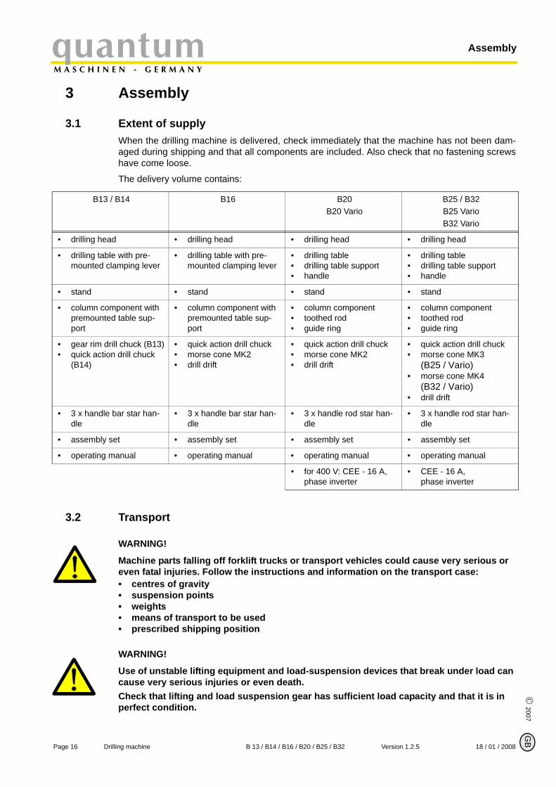
3 Assembly
3.1 Extent of supplyWhen the drilling machine is delivered, check immediately that the machine has not been dam-aged during shipping and that all components are included. Also check that no fastening screwshave come loose.
The delivery volume contains:
3.2 Transport
WARNING!
Machine parts falling off forklift trucks or transport vehicles could cause very serious or even fatal injuries. Follow the instructions and information on the transport case:• centres of gravity• suspension points• weights• means of transport to be used• prescribed shipping position
WARNING!
Use of unstable lifting equipment and load-suspension devices that break under load can cause very serious injuries or even death.Check that lifting and load suspension gear has sufficient load capacity and that it is in perfect condition.
B13 / B14 B16 B20B20 Vario
B25 / B32 B25 Vario B32 Vario
• drilling head • drilling head • drilling head • drilling head
• drilling table with pre-mounted clamping lever
• drilling table with pre-mounted clamping lever
• drilling table• drilling table support• handle
• drilling table• drilling table support• handle
• stand • stand • stand • stand
• column component with premounted table sup-port
• column component with premounted table sup-port
• column component• toothed rod• guide ring
• column component• toothed rod• guide ring
• gear rim drill chuck (B13)• quick action drill chuck
(B14)
• quick action drill chuck• morse cone MK2 • drill drift
• quick action drill chuck• morse cone MK2 • drill drift
• quick action drill chuck• morse cone MK3
(B25 / Vario) • morse cone MK4
(B32 / Vario) • drill drift
• 3 x handle bar star han-dle
• 3 x handle bar star han-dle
• 3 x handle rod star han-dle
• 3 x handle rod star han-dle
• assembly set • assembly set • assembly set • assembly set
• operating manual • operating manual • operating manual • operating manual
• for 400 V: CEE - 16 A, phase inverter
• CEE - 16 A, phase inverter
B
Page 16 Drilling machine B 13 / B14 / B16 / B20 / B25 / B32 Version 1.2.5 18 / 01 / 2008
quantumM A S C H I N E N - G E R M A N Y
Assembly
© 2
007
GB
Observe the rules for preventing accidents issued by your association for the prevention of accidents or other inspection authorities. Hold the loads properly. Never walk under suspended loads!
3.3 Storage
ATTENTION!
Improper storage may cause important parts to be damaged or destroyed. Store packed or unpacked parts only under the following ambient conditions:
„Environmental conditions“ on page 15
Consult Optimum Maschinen GmbH if the drilling machine and accessories have to be storedfor a period of over three monthes or under different external conditions than those given here.
3.4 Installation and assemby
3.4.1 Assembly
WARNING!
Danger of crushing when grouping, assembling and mounting the machine components.
Assembly of stand and tripod
INFORMATION
You need a hexagon spanner 17mm and the hexagon bolts contained in the delivery volume toassemble the drilling machine.
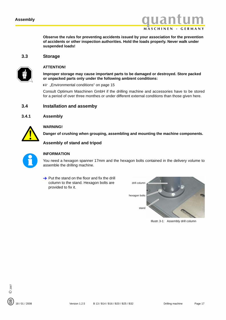
Put the stand on the floor and fix the drill column to the stand. Hexagon bolts are provided to fix it.
Illustr.3-1: Assembly drill column
drill column
hexagon bolts
stand
Page 1718 / 01 / 2008 Version 1.2.5 B 13 / B14 / B16 / B20 / B25 / B32 Drilling machine
AssemblyquantumM A S C H I N E N - G E R M A N Y
© 2007
G
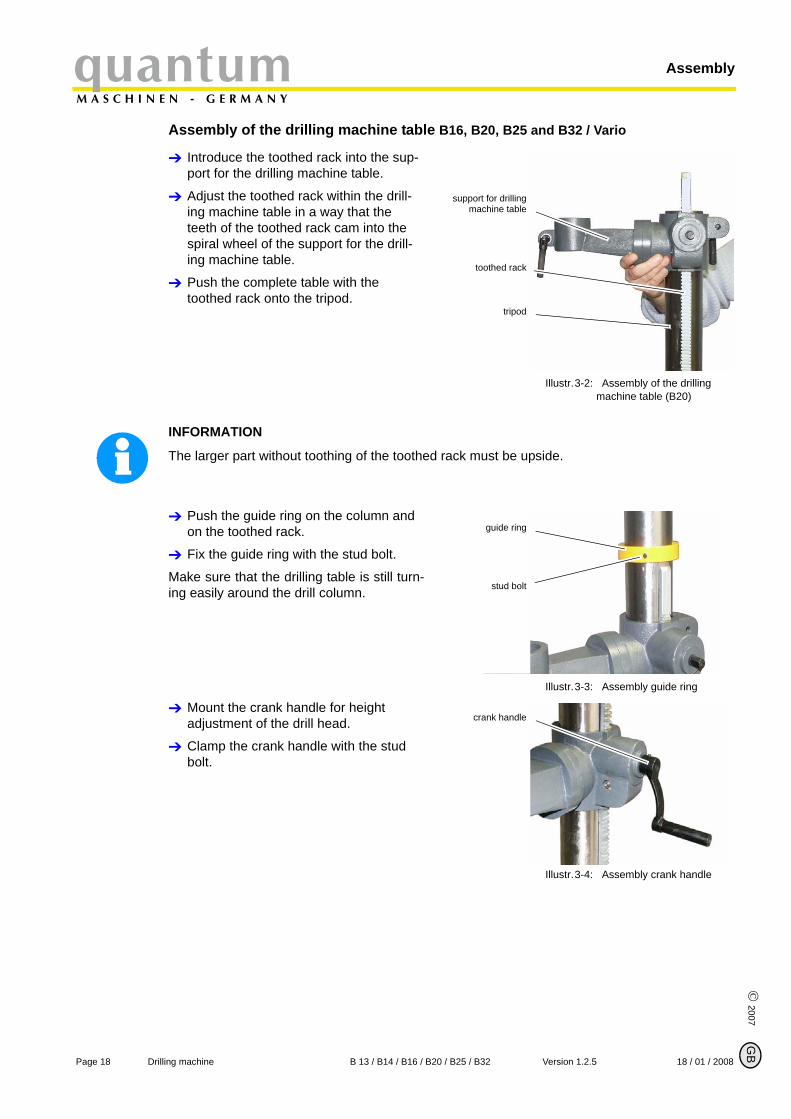
Assembly of the drilling machine table B16, B20, B25 and B32 / Vario
Introduce the toothed rack into the sup-port for the drilling machine table.
Adjust the toothed rack within the drill-ing machine table in a way that the teeth of the toothed rack cam into the spiral wheel of the support for the drill-ing machine table.
Push the complete table with the toothed rack onto the tripod.
Illustr.3-2: Assembly of the drilling machine table (B20)
INFORMATION
The larger part without toothing of the toothed rack must be upside.
Push the guide ring on the column and on the toothed rack.
Fix the guide ring with the stud bolt.
Make sure that the drilling table is still turn-ing easily around the drill column.
Illustr.3-3: Assembly guide ring
Mount the crank handle for height adjustment of the drill head.
Clamp the crank handle with the stud bolt.
Illustr.3-4: Assembly crank handle
support for drillingmachine table
toothed rack
tripod
guide ring
stud bolt
crank handle
B
Page 18 Drilling machine B 13 / B14 / B16 / B20 / B25 / B32 Version 1.2.5 18 / 01 / 2008
quantumM A S C H I N E N - G E R M A N Y
Assembly
© 2
007
GB
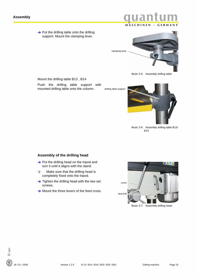
Put the drilling table onto the drilling support. Mount the clamping lever.
Illustr.3-5: Assembly drilling table
Mount the drilling table B13 , B14
Push the drilling table support withmounted drilling table onto the column.
Illustr.3-6: Assembly drilling table B13/B14
Assembly of the drilling head
Put the drilling head on the tripod and turn it until it aligns with the stand.
Make sure that the drilling head is completely fixed onto the tripod.
Tighten the drilling head with the two set screws.
Mount the three levers of the feed cross.
Illustr.3-7: Assembly drilling head
clamping lever
drilling table support
Lever
stud bolt
Page 1918 / 01 / 2008 Version 1.2.5 B 13 / B14 / B16 / B20 / B25 / B32 Drilling machine
AssemblyquantumM A S C H I N E N - G E R M A N Y
© 2007
G
3.4.2 Installation
Check the horizontal orientation of the base of the drilling machine with a spirit level.
Attach the drilling machine to the base using the holes in the stand.
The place where the drilling machine is installed must comply with ergonomic workplace require-ments.
ATTENTION!
Tighten the setscrews on the drilling machine only until it is firmly secured and can nei-ther move during operation nor be turned over.If the setscrews are too tight and the base is uneven, the stand of the drilling machine maybreak.
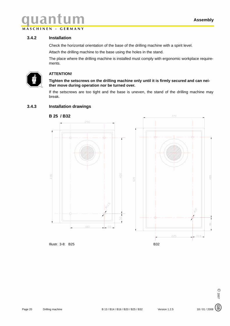
3.4.3 Installation drawings
B 25 / B32
Illustr. 3-8: B25 B32
B
Page 20 Drilling machine B 13 / B14 / B16 / B20 / B25 / B32 Version 1.2.5 18 / 01 / 2008
quantumM A S C H I N E N - G E R M A N Y
Assembly
© 2
007
GB
3.5 First use
WARNING!
Staff and equipment may be endangered if the drilling machine is first used by unexpert staff. We do not take responsibility for damage caused by incorrect commissioning.
Power supply
Connect the main plug of the drilling machine to the power supply.
Check the fuse protection of your power supply to the technical data for the power consump-tion of the engine.
ATTENTION!
Please pay attention that all three phases (L1, L2, L3) for 400V - drilling machines are connected correctly.Most engine failures result from incorrect connection, for instance the neutral connector (N) is being connected to a phase. This might lead to the following results: • The engine does get quickly very hot.• The engine noise increases, i. e. becomes louder.• The engine has no power.When the phases are connected incorrectly, the guarantee is null and void.
ATTENTION!
Drilling machines with frequency converter should not be operated with a CEE plug. Con-nect the machine permanently to a connection box (see EN 50178/5.2.11.1)
INFORMATION
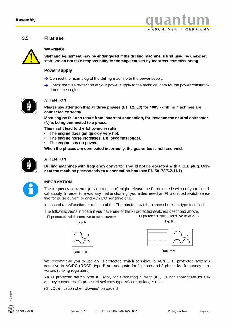
The frequency converter (driving regulator) might release the FI protected switch of your electri-cal supply. In order to avoid any malfunctioning, you either need an FI protected switch sensi-tive for pulse current or and AC / DC sensitive one.
In case of a malfunction or release of the FI protected switch, please check the type installed.
The following signs indicate if you have one of the FI protected switches described above.
We recommend you to use an FI protected switch sensitive to AC/DC. FI protected switchessensitive to AC/DC (RCCB, type B are adequate for 1 phase and 3 phase fed frequency con-verters (driving regulators).
An FI protected switch type AC (only for alternating current (AC)) is not appropriate for fre-quency converters. FI protected switches type AC are no longer used.
„Qualification of employees“ on page 8
FI protected switch sensitive to pulse currentTyp A
FI protected switch sensitive to AC/DCTyp B
300 mA 300 mA
Page 2118 / 01 / 2008 Version 1.2.5 B 13 / B14 / B16 / B20 / B25 / B32 Drilling machine
AssemblyquantumM A S C H I N E N - G E R M A N Y
© 2007
G
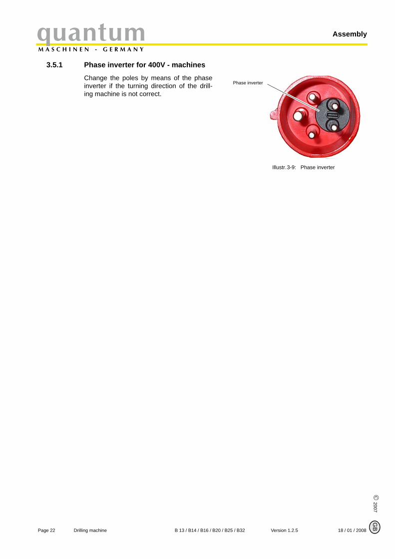
3.5.1 Phase inverter for 400V - machines
Change the poles by means of the phaseinverter if the turning direction of the drill-ing machine is not correct.
Illustr.3-9: Phase inverter
Phase inverter
B
Page 22 Drilling machine B 13 / B14 / B16 / B20 / B25 / B32 Version 1.2.5 18 / 01 / 2008
quantumM A S C H I N E N - G E R M A N Y
Handling
© 2
007
GB
4 Handling
4.1 SafetyUse the drilling machine only under the following conditions:
The drilling machine is in proper working order.
The drilling machine is used as prescribed.
The instruction manual has been followed.
All safety devices are installed and activated.
All malfunctions should be eliminated immediately. Stop the machine immediately at an event ofany malfunction in operation and make sure it cannot be started up accidentally or withoutauthorization.
Notify the person responsible immediately of any modification.
„Safety during operation“ on page 12
4.2 Control and indicating elements
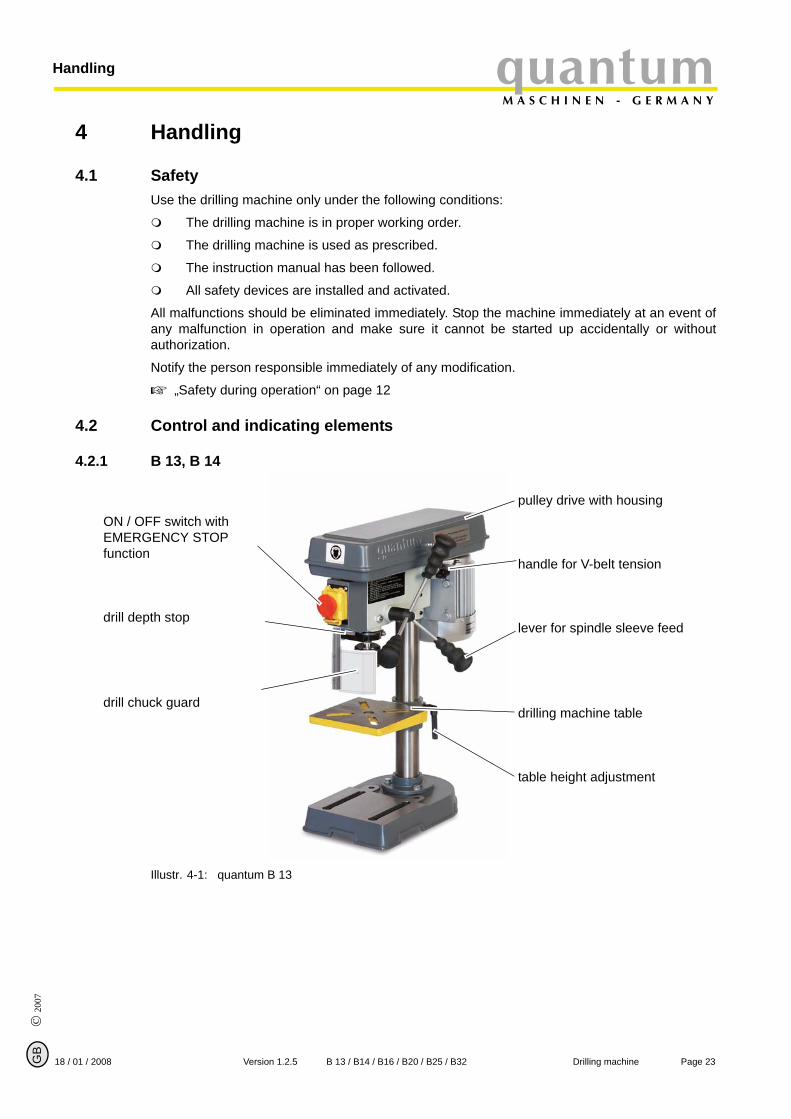
4.2.1 B 13, B 14
Illustr. 4-1: quantum B 13
pulley drive with housing
handle for V-belt tension
lever for spindle sleeve feed
drilling machine table
table height adjustment
ON / OFF switch with EMERGENCY STOP function
drill depth stop
drill chuck guard
Page 2318 / 01 / 2008 Version 1.2.5 B 13 / B14 / B16 / B20 / B25 / B32 Drilling machine
HandlingquantumM A S C H I N E N - G E R M A N Y
© 2007
G
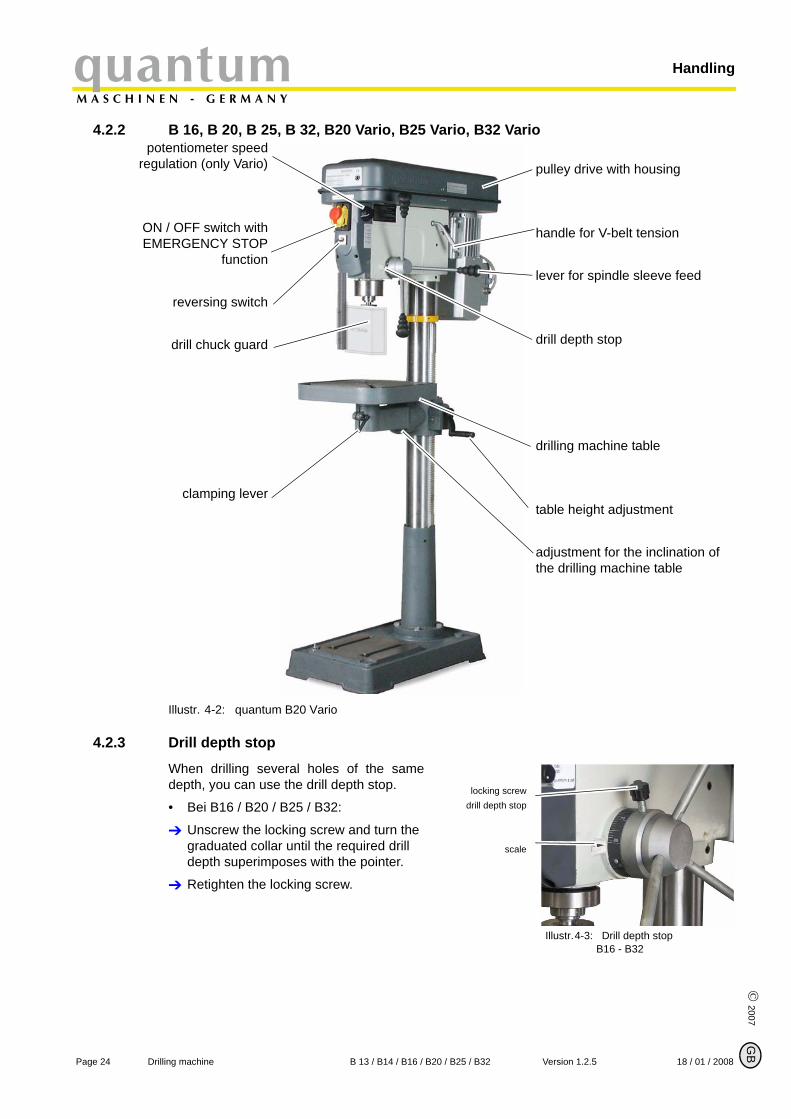
4.2.2 B 16, B 20, B 25, B 32, B20 Vario, B25 Vario, B32 Vario
Illustr. 4-2: quantum B20 Vario
4.2.3 Drill depth stop
When drilling several holes of the samedepth, you can use the drill depth stop.
• Bei B16 / B20 / B25 / B32:
Unscrew the locking screw and turn the graduated collar until the required drill depth superimposes with the pointer.
Retighten the locking screw.
Illustr.4-3: Drill depth stopB16 - B32
pulley drive with housing
handle for V-belt tension
lever for spindle sleeve feed
drill depth stop
drilling machine table
table height adjustment
adjustment for the inclination of the drilling machine table
potentiometer speedregulation (only Vario)
ON / OFF switch withEMERGENCY STOP
function
reversing switch
drill chuck guard
clamping lever
locking screwdrill depth stop
scale
B
Page 24 Drilling machine B 13 / B14 / B16 / B20 / B25 / B32 Version 1.2.5 18 / 01 / 2008
quantumM A S C H I N E N - G E R M A N Y
Handling
© 2
007
GB
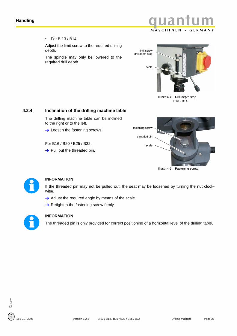
• For B 13 / B14:
Adjust the limit screw to the required drillingdepth.
The spindle may only be lowered to therequired drill depth.
Illustr.4-4: Drill depth stopB13 - B14
4.2.4 Inclination of the drilling machine table
The drilling machine table can be inclinedto the right or to the left.
Loosen the fastening screws.
For B16 / B20 / B25 / B32:
Pull out the threaded pin.
Illustr.4-5: Fastening screw
INFORMATION
If the threaded pin may not be pulled out, the seat may be loosened by turning the nut clock-wise.
Adjust the required angle by means of the scale.
Retighten the fastening screw firmly.
INFORMATION
The threaded pin is only provided for correct positioning of a horizontal level of the drilling table.
limit screwdrill depth stop
scale
fastening screw
threaded pin
scale
Page 2518 / 01 / 2008 Version 1.2.5 B 13 / B14 / B16 / B20 / B25 / B32 Drilling machine
HandlingquantumM A S C H I N E N - G E R M A N Y
© 2007
G
4.3 Speed alternation
WARNING!
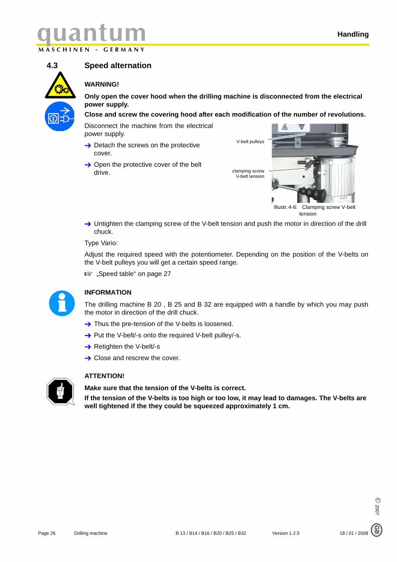
Only open the cover hood when the drilling machine is disconnected from the electrical power supply.Close and screw the covering hood after each modification of the number of revolutions.Disconnect the machine from the electricalpower supply.
Detach the screws on the protective cover.
Open the protective cover of the belt drive.
Illustr.4-6: Clamping screw V-belt tension
Untighten the clamping screw of the V-belt tension and push the motor in direction of the drill chuck.
Type Vario:
Adjust the required speed with the potentiometer. Depending on the position of the V-belts onthe V-belt pulleys you will get a certain speed range.
„Speed table“ on page 27
INFORMATION
The drilling machine B 20 , B 25 and B 32 are equipped with a handle by which you may pushthe motor in direction of the drill chuck.
Thus the pre-tension of the V-belts is loosened.
Put the V-belt/-s onto the required V-belt pulley/-s.
Retighten the V-belt/-s
Close and rescrew the cover.
ATTENTION!
Make sure that the tension of the V-belts is correct. If the tension of the V-belts is too high or too low, it may lead to damages. The V-belts are well tightened if the they could be squeezed approximately 1 cm.
V-belt pulleys
clamping screwV-belt tension
B
Page 26 Drilling machine B 13 / B14 / B16 / B20 / B25 / B32 Version 1.2.5 18 / 01 / 2008
quantumM A S C H I N E N - G E R M A N Y
Handling
© 2
007
GB
4.3.1 Speed table
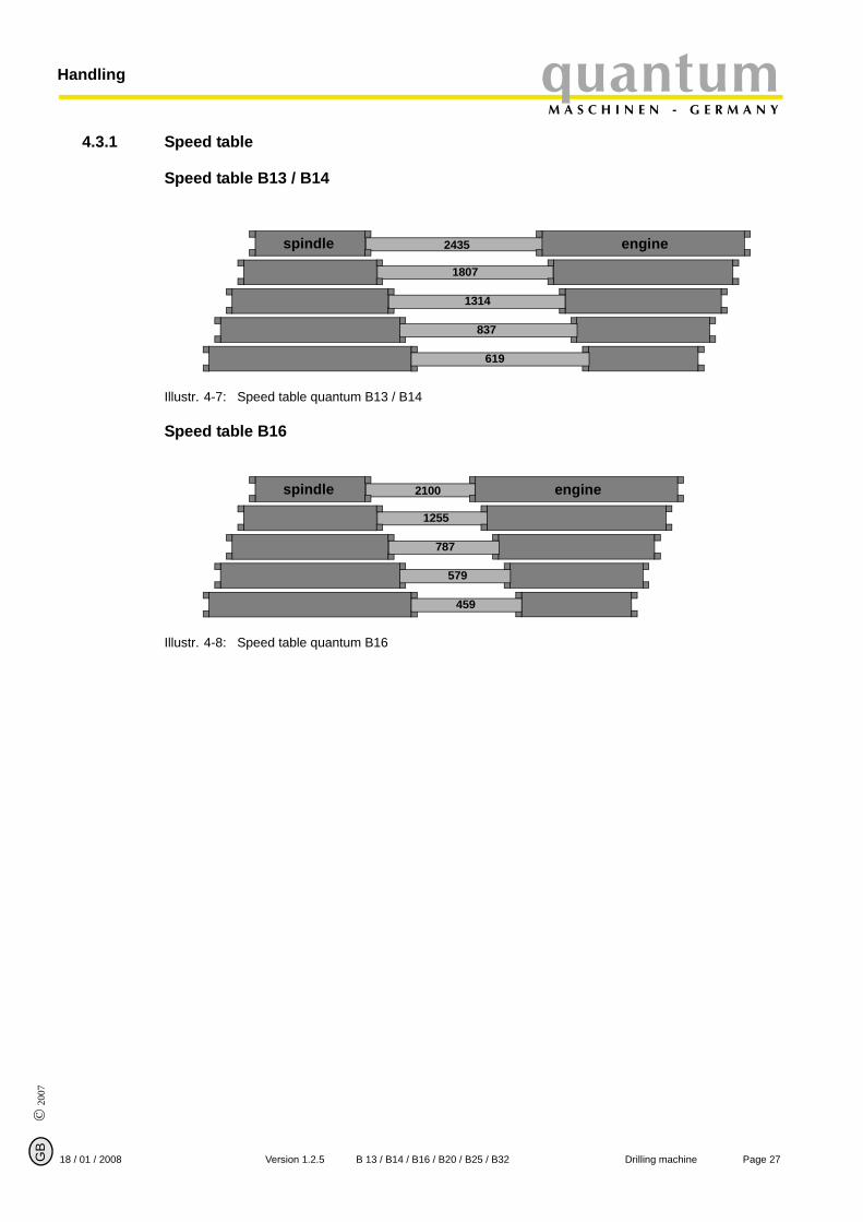
Speed table B13 / B14
Illustr. 4-7: Speed table quantum B13 / B14
Speed table B16
Illustr. 4-8: Speed table quantum B16
2435spindle engine
1807
1314
837
619
2100spindle engine
1255
787
579
459
Page 2718 / 01 / 2008 Version 1.2.5 B 13 / B14 / B16 / B20 / B25 / B32 Drilling machine
HandlingquantumM A S C H I N E N - G E R M A N Y
© 2007
G
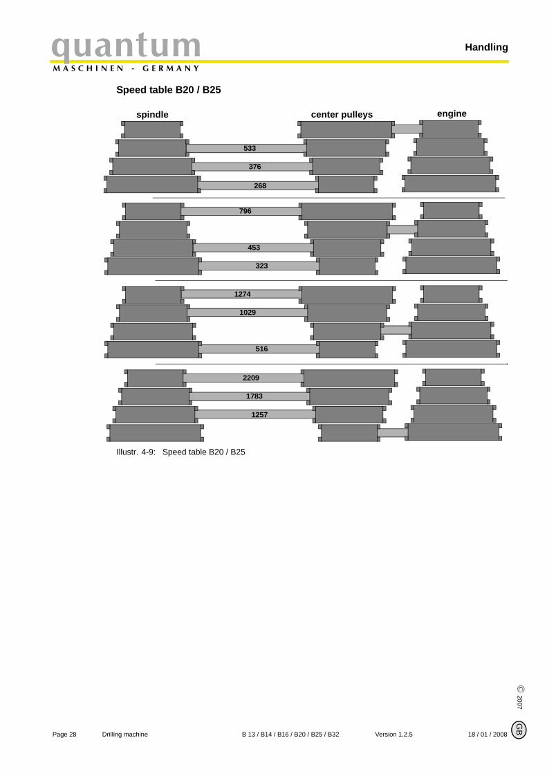
Speed table B20 / B25
Illustr. 4-9: Speed table B20 / B25
spindle
533
376
268
796
453
323
1029
1274
516
1783
2209
1257
enginecenter pulleys
B
Page 28 Drilling machine B 13 / B14 / B16 / B20 / B25 / B32 Version 1.2.5 18 / 01 / 2008
quantumM A S C H I N E N - G E R M A N Y
Handling
© 2
007
GB
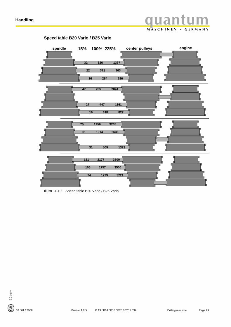
Speed table B20 Vario / B25 Vario
Illustr. 4-10: Speed table B20 Vario / B25 Vario
spindle
526
371
264
785
447
318
1014
1256
509
1757
2177
1239
enginecenter pulleys
1367
963
686
2041
1161
827
2636
3265
1323
3500
3500
3221
32
22
16
47
27
19
61
75
31
105
131
74
15% 100% 225%
Page 2918 / 01 / 2008 Version 1.2.5 B 13 / B14 / B16 / B20 / B25 / B32 Drilling machine
HandlingquantumM A S C H I N E N - G E R M A N Y
© 2007
G
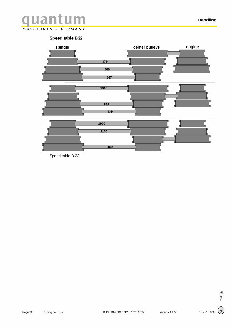
Speed table B32
Speed table B 32
spindle
379
288
167
1368
585
339
1106
1970
489
enginecenter pulleys
B
Page 30 Drilling machine B 13 / B14 / B16 / B20 / B25 / B32 Version 1.2.5 18 / 01 / 2008
quantumM A S C H I N E N - G E R M A N Y
Handling
© 2
007
GB
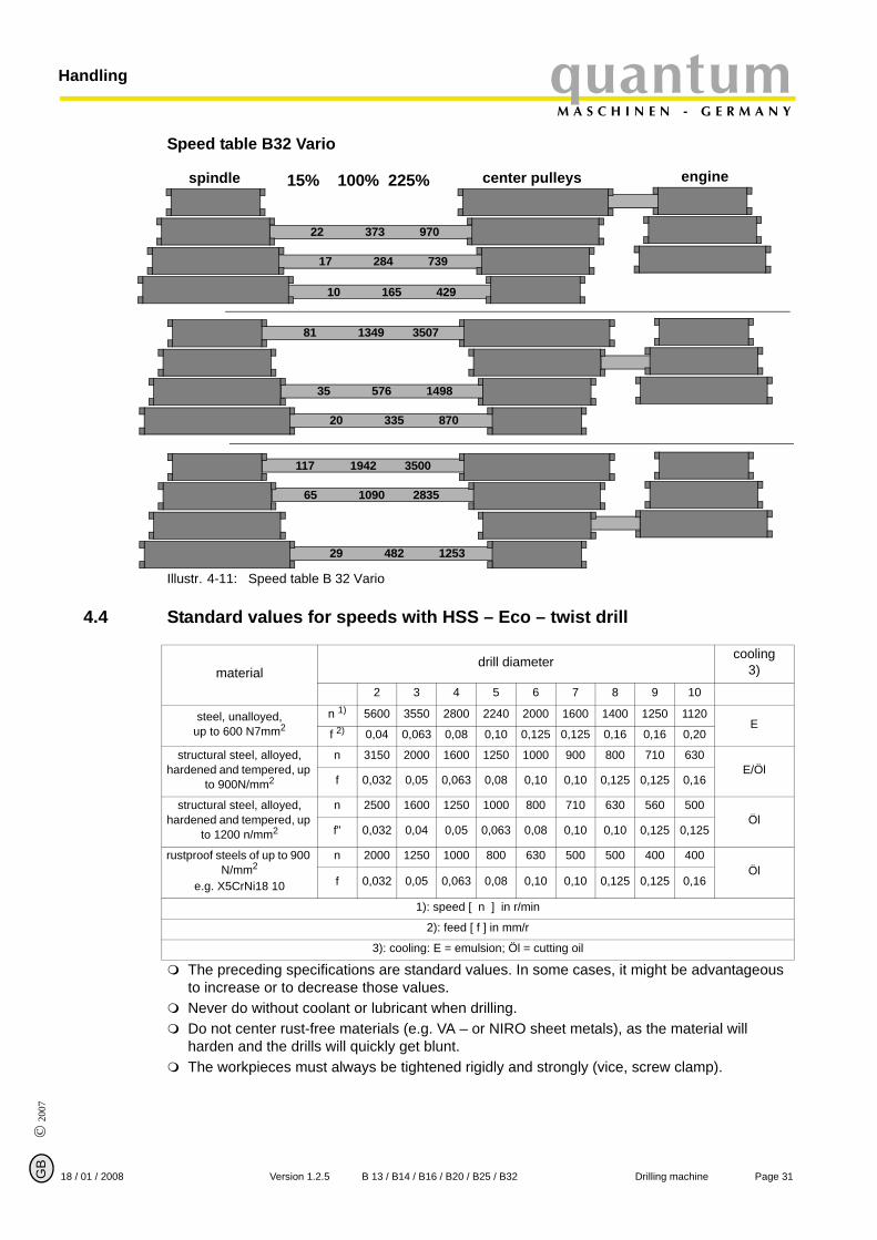
Speed table B32 Vario
Illustr. 4-11: Speed table B 32 Vario
4.4 Standard values for speeds with HSS – Eco – twist drill
The preceding specifications are standard values. In some cases, it might be advantageous to increase or to decrease those values.Never do without coolant or lubricant when drilling.Do not center rust-free materials (e.g. VA – or NIRO sheet metals), as the material will harden and the drills will quickly get blunt. The workpieces must always be tightened rigidly and strongly (vice, screw clamp).
spindle
373
284
165
1349
576
335
1090
1942
482
enginecenter pulleys15% 100% 225%
970
739
429
3507
1498
870
2835
3500
1253
22
17
10
81
35
20
65
117
29
materialdrill diameter cooling
3)2 3 4 5 6 7 8 9 10
steel, unalloyed, up to 600 N7mm2
n 1) 5600 3550 2800 2240 2000 1600 1400 1250 1120E
f 2) 0,04 0,063 0,08 0,10 0,125 0,125 0,16 0,16 0,20
structural steel, alloyed, hardened and tempered, up
to 900N/mm2
n 3150 2000 1600 1250 1000 900 800 710 630E/Öl
f 0,032 0,05 0,063 0,08 0,10 0,10 0,125 0,125 0,16
structural steel, alloyed, hardened and tempered, up
to 1200 n/mm2
n 2500 1600 1250 1000 800 710 630 560 500Öl
f" 0,032 0,04 0,05 0,063 0,08 0,10 0,10 0,125 0,125
rustproof steels of up to 900 N/mm2
e.g. X5CrNi18 10
n 2000 1250 1000 800 630 500 500 400 400Öl
f 0,032 0,05 0,063 0,08 0,10 0,10 0,125 0,125 0,16
1): speed [ n ] in r/min
2): feed [ f ] in mm/r
3): cooling: E = emulsion; Öl = cutting oil
Page 3118 / 01 / 2008 Version 1.2.5 B 13 / B14 / B16 / B20 / B25 / B32 Drilling machine
HandlingquantumM A S C H I N E N - G E R M A N Y
© 2007
G
4.5 Drill chuck
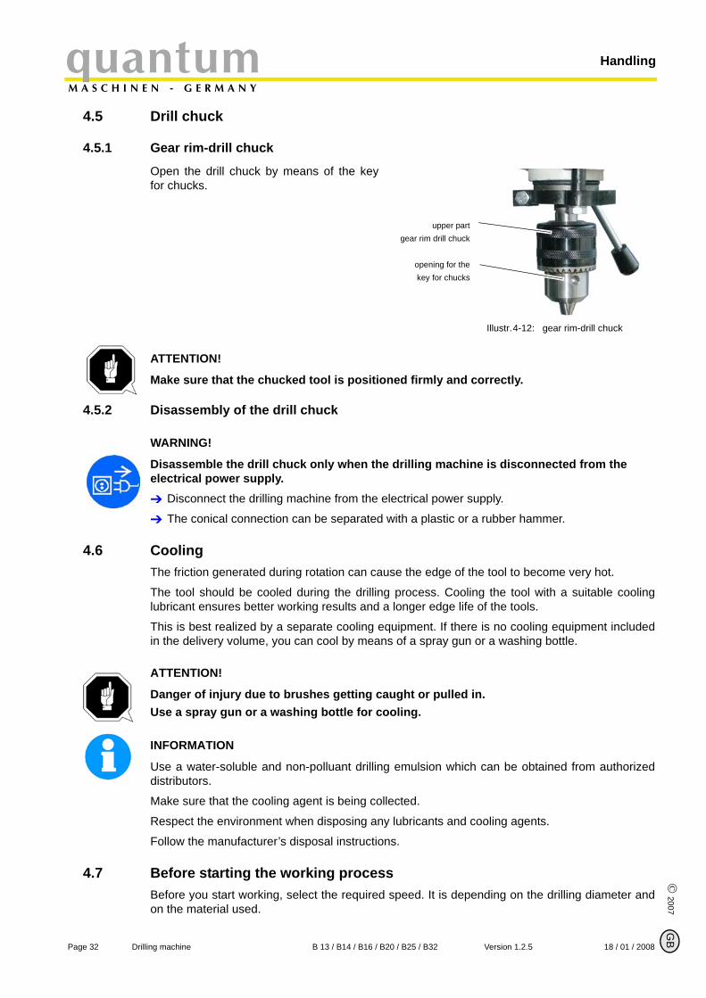
4.5.1 Gear rim-drill chuck
Open the drill chuck by means of the keyfor chucks.
Illustr.4-12: gear rim-drill chuck
ATTENTION!
Make sure that the chucked tool is positioned firmly and correctly.
4.5.2 Disassembly of the drill chuck
WARNING!
Disassemble the drill chuck only when the drilling machine is disconnected from the electrical power supply.
Disconnect the drilling machine from the electrical power supply.
The conical connection can be separated with a plastic or a rubber hammer.
4.6 CoolingThe friction generated during rotation can cause the edge of the tool to become very hot.
The tool should be cooled during the drilling process. Cooling the tool with a suitable coolinglubricant ensures better working results and a longer edge life of the tools.
This is best realized by a separate cooling equipment. If there is no cooling equipment includedin the delivery volume, you can cool by means of a spray gun or a washing bottle.
ATTENTION!
Danger of injury due to brushes getting caught or pulled in.Use a spray gun or a washing bottle for cooling.
INFORMATION
Use a water-soluble and non-polluant drilling emulsion which can be obtained from authorizeddistributors.
Make sure that the cooling agent is being collected.
Respect the environment when disposing any lubricants and cooling agents.
Follow the manufacturer’s disposal instructions.
4.7 Before starting the working processBefore you start working, select the required speed. It is depending on the drilling diameter andon the material used.
upper partgear rim drill chuck
opening for thekey for chucks
B
Page 32 Drilling machine B 13 / B14 / B16 / B20 / B25 / B32 Version 1.2.5 18 / 01 / 2008
quantumM A S C H I N E N - G E R M A N Y
Handling
© 2
007
GB
„Speed table“ on page 27
WARNING!
For drilling jobs, it is necessary to clamp the workpiece firmly to prevent the bit catching on the piece. Example of suitable clamping devices include a machine vice or clamping jaws.Put a wooden or plastic board beneath the workpiece to avoid drilling through to the work table,vice, etc.
If necessary, adjust the required drill depth by means of the drill depth stop in order to achieve aconstant result.
Use a dust remover unit while working with wood. Sawdust can be health hazardous. Also use asuitable protective mask for any work which generates dust.
4.8 During the working processThe spindle sleeve feed is being performed by the star grip. Make sure that the feed is being ata regular pace and not too fast.
The reset of the spindle sleeve is being performed by a track recoil spring.
WARNING!
Danger of clothing and / or long hair getting caught.• Make sure to wear a well-fitting work suit during drilling work.• Do not use gloves.• If necessary, wear a hairnet.
ATTENTION!
Danger of collision by the levers of the star grip.Do not let the star grip get loose when resetting the drill sleeve.Thin bits break easily.
In case of deep drilling, remove the bit from time to time, to remove drilling chips from the borehole. Some drops of oil reduce friction and ensure a longer edge life of the bit.
CAUTION!
Danger of crushing! Do not place your hand between the drill head and the spindle sleeve.
Page 3318 / 01 / 2008 Version 1.2.5 B 13 / B14 / B16 / B20 / B25 / B32 Drilling machine
MaintenancequantumM A S C H I N E N - G E R M A N Y
© 2007
G
5 Maintenance
In this chapter you will find important information about
• inspection,• maintenance,• repair of the drilling machine.
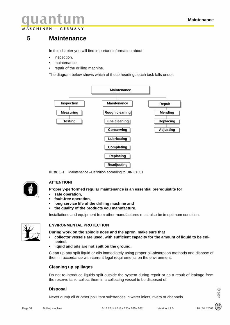
The diagram below shows which of these headings each task falls under.
Illustr. 5-1: Maintenance –Definition according to DIN 31051
ATTENTION!
Properly-performed regular maintenance is an essential prerequistite for • safe operation,• fault-free operation,• long service life of the drilling machine and• the quality of the products you manufacture.Installations and equipment from other manufactures must also be in optimum condition.
ENVIRONMENTAL PROTECTION
During work on the spindle nose and the apron, make sure that • collector vessels are used, with sufficient capacity for the amount of liquid to be col-
lected,• liquid and oils are not spilt on the ground.Clean up any spilt liquid or oils immediately using proper oil-absorption methods and dispose ofthem in accordance with current legal requirements on the environment.
Cleaning up spillages
Do not re-introduce liquids spilt outside the system during repair or as a result of leakage fromthe reserve tank: collect them in a collecting vessel to be disposed of.
Disposal
Never dump oil or other pollutant substances in water inlets, rivers or channels.
Maintenance
Inspection Maintenance Repair
Measuring Rough cleaning Mending
Testing Fine cleaning Replacing
Conserving
Lubricating
Completing
Replacing
Readjusting
Adjusting
B
Page 34 Drilling machine B 13 / B14 / B16 / B20 / B25 / B32 Version 1.2.5 18 / 01 / 2008
quantumM A S C H I N E N - G E R M A N Y
Maintenance
© 2
007
GB
Used oils must be delivered to a collection centre. Consult your superior if you do not knowwhere the collection centre is.
5.1 Safety
WARNING!
The consequences of incorrect maintenance and repair work may include:• very serious injury to personnel working on the drilling machine,• damage to the drilling machine.• Only qualified personnel should carry out maintenance and repair work on the drilling
machine.
5.1.1 Preparation
WARNING!
Only carry out work on the drilling machine if it has been switched off using the main switch and secured with a padlock to prevent the machine from being turned on.Attach a warning label.
5.1.2 Restarting
Before restarting run a safety check.
„Safety check“ on page 11
WARNING!
Before connecting the machine you must check that • there is no danger for personnel• the drilling machine is undamaged.
5.2 Inspection and maintenanceThe type and extent of wear depends to a large extent on individual usage and service condi-tions. Therefore, the indicated intervals only apply for the approved conditions.
Interval Where? What? How?
start of shift
after each maintenance or repair operation
drill
ing
mac
hine
„Safety check“ on page 11
Page 3518 / 01 / 2008 Version 1.2.5 B 13 / B14 / B16 / B20 / B25 / B32 Drilling machine
MaintenancequantumM A S C H I N E N - G E R M A N Y
© 2007
G
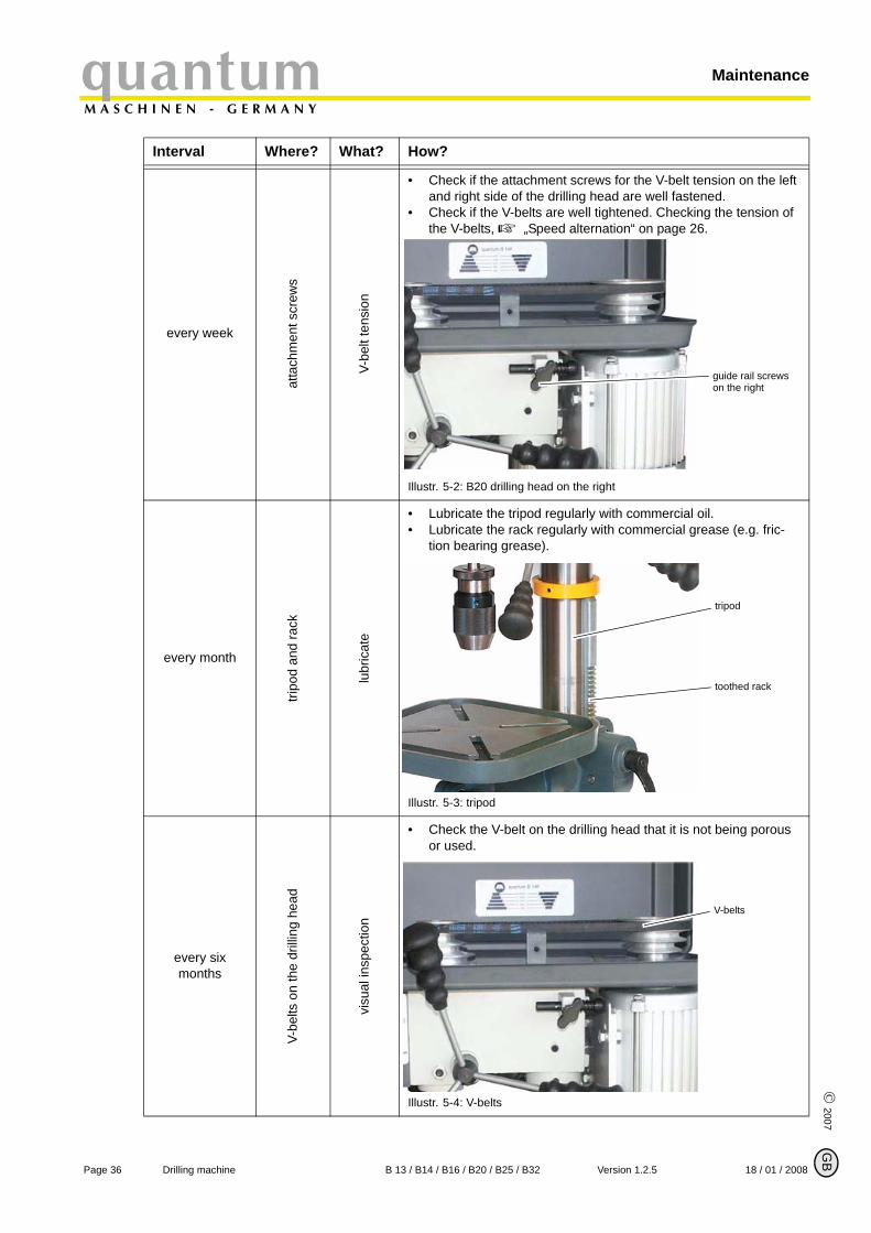
every week
atta
chm
ent s
crew
s
V-be
lt te
nsio
n
• Check if the attachment screws for the V-belt tension on the left and right side of the drilling head are well fastened.
• Check if the V-belts are well tightened. Checking the tension of the V-belts, „Speed alternation“ on page 26.
Illustr. 5-2: B20 drilling head on the right
every month
tripo
d an
d ra
ck
lubr
icat
e
• Lubricate the tripod regularly with commercial oil.• Lubricate the rack regularly with commercial grease (e.g. fric-
tion bearing grease).
Illustr. 5-3: tripod
every six months
V-be
lts o
n th
e dr
illing
hea
d
visu
al in
spec
tion
• Check the V-belt on the drilling head that it is not being porous or used.
Illustr. 5-4: V-belts
Interval Where? What? How?
guide rail screws on the right
tripod
toothed rack
V-belts
B
Page 36 Drilling machine B 13 / B14 / B16 / B20 / B25 / B32 Version 1.2.5 18 / 01 / 2008
quantumM A S C H I N E N - G E R M A N Y
Maintenance
© 2
007
GB
5.3 RepairFor any repair work, request the assistance of an employee of Optimum Maschinen GmbH’stechnical service or send us the drilling machine.
If the repairs are carried out by qualified technical staff, they must follow the indications given inthis manual.
Optimum Maschinen GmbH does not take responsiblity nor does it guarantee against damageand operating malfunctions resulting from failure to observe this operating manual.
For repairs only use
• faultless and suitable tools,• original parts or parts from series expressly authorized by Optimum Maschinen GmbH.
every six months
elec
tric
chec
k
Check the electrical equipment/ parts of the drilling machine.
„Qualification of employees“ on page 8
Interval Where? What? How?
Page 3718 / 01 / 2008 Version 1.2.5 B 13 / B14 / B16 / B20 / B25 / B32 Drilling machine
Ersatzteile - Spare parts B13, B14, B16, B20, B25, B32quantumM A S C H I N E N - G E R M A N Y
6 Ersatzteile - Spare parts B13, B14, B16, B20, B25, B32
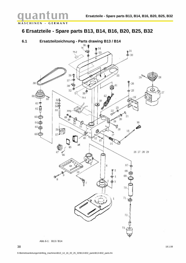
6.1 Ersatzteilzeichnung - Parts drawing B13 / B14
Abb.6-1: B13 / B14
38
S:\Betriebsanleitungen\drilling_machines\B13_14_16_20_25_32\B13-B32_parts\B13-B32_parts.fm
18.1.08
quantumM A S C H I N E N - G E R M A N Y
Ersatzteile - Spare parts B13, B14, B16, B20, B25, B32
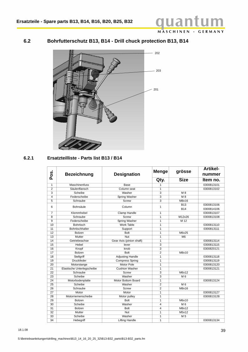
6.2 Bohrfutterschutz B13, B14 - Drill chuck protection B13, B14
18.1.08
S:\Betriebsanleitung
202
201
203
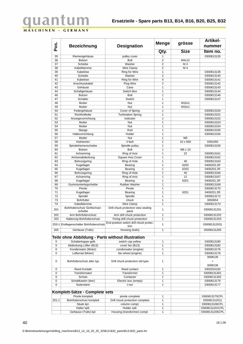
6.2.1 Ersatzteilliste - Parts list B13 / B14
Pos. Bezeichnung Designation Menge grösse Artikel-
nummerQty. Size Item no.
1 Maschinenfuss Base 1 03008131012 Säulenflansch Column seat 1 03008131023 Scheibe Washer 3 M 84 Federscheibe Spring Washer 3 M 8 5 Schraube Screw 3 M8x16
6 Bohrsäule Column 1B13B14
03008131060300814106
7 Klemmhebel Clamp Handle 1 03008131078 Schraube Screw 1 M12x26 03008131089 Federscheibe Spring Washer 1 M 1210 Bohrtisch Work Table 1 030081311011 Bohrtischhalter Support 1 030081311112 Bolzen Bolt 1 M6x2513 Mutter Nut 1 M614 Getriebeachse Gear Axis (pinion shaft) 1 030081311415 Hebel lever 3 030081311516 Knopf knob 3 030082012117 Bolzen Bolt 2 M8x1018 Stellgriff Adjusting Handle 1 030081311819 Druckfeder Compress Spring 1 030081311920 Motorstange Motor Pole 1 030081312021 Elastische Unterlegscheibe Cushion Washer 1 030081312122 Schraube Screw 3 M6x1223 Scheibe Washer 3 M 624 Motorbodenplatte Motor Bottom Board 1 030081312425 Scheibe Washer 2 M 626 Schraube Screw 2 M8x1627 Motor Motor 1 030081312728 Motorriemenscheibe Motor pulley 1 030081312829 Bolzen Bolt 1 M6x1030 Scheibe Washer 4 M 631 Bolzen Bolt 4 M8x1232 Mutter Nut 1 M5x1233 Scheibe Washer 1 M 534 Hebegriff Lifting Handle 1 0300813134
en\drilling_machines\B13_14_16_20_25_32\B13-B32_parts\B13-B32_parts.fm
39
Ersatzteile - Spare parts B13, B14, B16, B20, B25, B32quantumM A S C H I N E N - G E R M A N Y
40
S:\Betriebsanleitunge
35 Riemengehäuse pulley cover 1 030081313536 Bolzen Bolt 2 M4x1237 Scheibe Washer 2 M 438 Kabelklemme Wire Clamp 2 M 439 Kabelöse Ring for Wire 1 030081313940 Scheibe Washer 2 030081314041 Kabelöse Ring for Wire 4 030081314142 Anschlusskabel Plug Wire 2 030081314243 Gehäuse Case 1 030081314344 Schaltgehäuse Switch Box 1 030081314446 Bolzen Bolt 1 030081314647 Schalter Switch 1 030081314748 Mutter Nut 1 M10x149 Mutter Nut 1 M10x150 Federgehäuse Cover of Spring 1 030081315051 Rückholfeder Turbination Spring 1 030081315152 Anzeigevorrichtung Indicator 1 030081315253 Mutter Nut 1 030081315354 Mutter Nut 1 030081315455 Stange Rod 1 030081315556 Haltevorrichtung Holder 1 030081315657 Mutter Nut 1 M658 Keilriemen V-belt 1 10 x 650 039105059 Spindelriemenscheibe Spindle pulley 1 030081315960 Bolzen Bolt 1 M6 x 1061 Achsenring Ring of Axis 1 22 030081316162 Achsenabdeckung Square Axis Cover 1 030081316263 Bohrungsring Ring of Hole 1 40 030081316364 Kugellager Bearing 1 6203 0406203.2R65 Kugellager Bearing 1 6203 0406203.2R66 Bohrungsring Ring of Hole 1 40 030081316667 Achsenring Ring of Axis 1 12 030081316768 Kugellager Bearing 1 6201 0406201.2R69 Gummiunterlegscheibe Rubber Washer 1 030081316970 Pinole Pinole 1 030081317071 Kugellager Bearing 1 6201 0406201.2R72 Spindel Spindle 1 030081317273 Bohrfutter chuck 1 305065474 Kabelklemme Wire Clamp 1 0300813174
201 Bohrfutterschutz Sichtschutz-scheibe
Drill chuck protection view sealing pane 1 03008131201
202 Arm Bohrfutterschutz Arm drill chuck protection 1 03008131202203 Halterung Bohrfutterschutz Fixing drill chuck protection 1 03008131203
203-1 Endlagenschalter Bohrfutterschutz End position switch drill chuck protec-tion 1 030081312031
205 Gehäuse (Trafo) Housing (trafo) 1 03008131205
Teile ohne Abbildung - Parts without illustration0 Schalterkappe gelb switch cap yellow 1 03008131800 Abdeckung Lüfter (B13) cover fan (B13) 1 03008131820 Kondensator (Motor) condensator (engine) 1 03008131760 Lüfterrad (Motor) fan wheel (engine) 1 0300813178
0 Bohrfutterschutz alter typ Drill chuck protection old type 13008135
+3008136
0 Reed Kontakt Reed contact 1 03020241920 Transformator Transformer 1 030081313010 Schütz Contactor 1 030081313020 Schaltkasten (leer) Electric box (empty) 1 03008131790 Nutenstein t-nut 1 0300813177
Komplett-Sätze - Complete setsPinole komplett pinole complete 1 0300813170CPL
201-1 Bohrfutterschutz komplett Drill chuck protection complete 1 030081312011Säule kpl. column compl. 1 0300813106CPLHalter kplt. Holder cplt. 1 03008131201CPL
Gehäuse (Trafo) kpl. Housing (transformer) compl. 1 03008131205CPL
Pos. Bezeichnung Designation Menge grösse Artikel-
nummerQty. Size Item no.
n\drilling_machines\B13_14_16_20_25_32\B13-B32_parts\B13-B32_parts.fm
18.1.08
quantumM A S C H I N E N - G E R M A N Y
Ersatzteile - Spare parts B13, B14, B16, B20, B25, B32
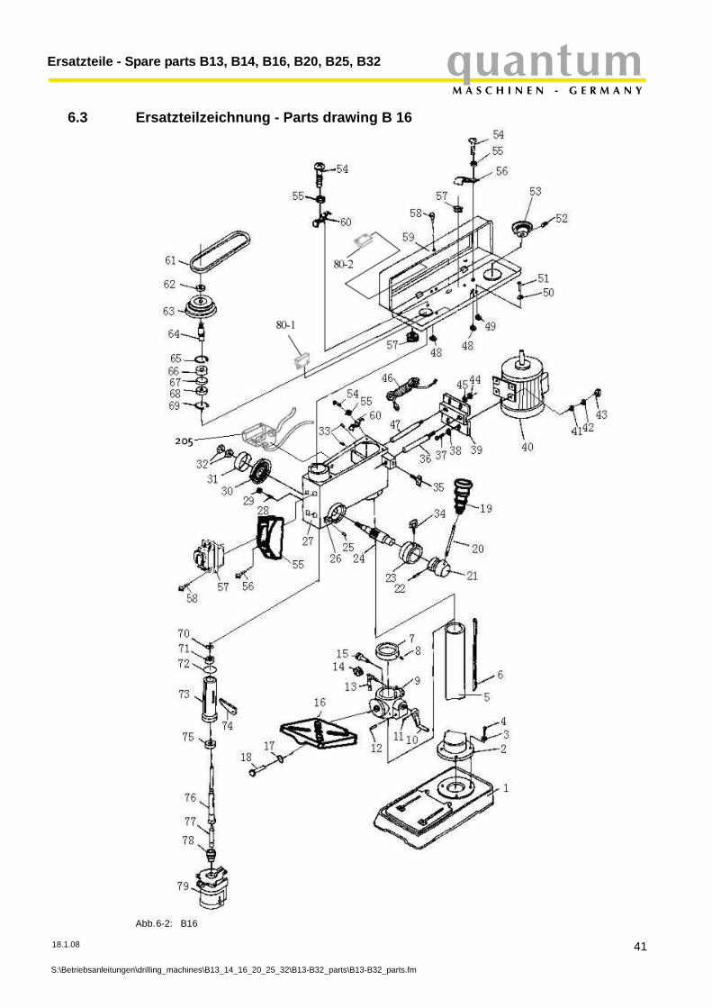
6.3 Ersatzteilzeichnung - Parts drawing B 16
Abb.6-2: B16
18.1.08
S:\Betriebsanleitungen\drilling_machines\B13_14_16_20_25_32\B13-B32_parts\B13-B32_parts.fm
41
Ersatzteile - Spare parts B13, B14, B16, B20, B25, B32quantumM A S C H I N E N - G E R M A N Y
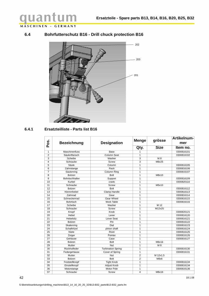
6.4 Bohrfutterschutz B16 - Drill chuck protection B16
42
S:\Betriebsanleitunge
202
201
203
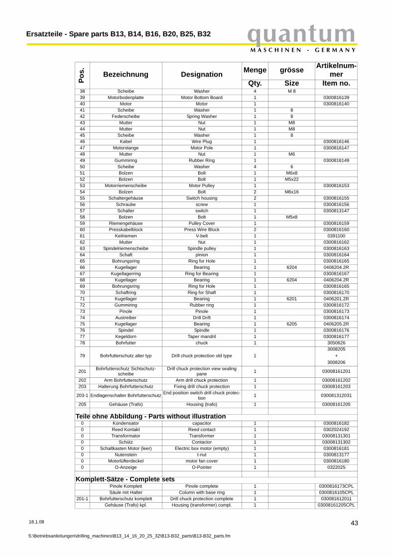
6.4.1 Ersatzteilliste - Parts list B16
Pos. Bezeichnung Designation Menge grösse Artikelnum-
merQty. Size Item no.
1 Maschinenfuss Base 1 03008161012 Säulenflansch Column Seat 1 03008161023 Scheibe Washer 3 M 84 Schraube Screw 3 M8x255 Säule Column 1 03008161056 Zahnstange Rack 1 03008161067 Säulenring Column Ring 1 03008161078 Bolzen Bolt 1 M8x109 Bohrtischhalter Support 1 030081610910 Kurbel crank 1 030082011011 Schraube Screw 1 M5x1012 Bolzen Bolt 1 030081611213 Klemmhebel Clamp Handle 1 030081611314 Zahnrad Gear 1 030081611415 Schneckenrad Gear Wheel 1 030081611516 Bohrtisch Work Table 1 030081611617 Scheibe Washer 1 M 1218 Schraube Screw 1 M12x2519 Knopf Knob 1 030082012120 Hebel Lever 1 030081612021 Hebelsitz Lever Seat 1 030081612122 Bolzen Pin 1 030081612223 Skalenring Dial 1 030081612324 Schaftritzel pinion shaft 1 030081612425 Niete Rivet 1 030081612526 Zeiger Pointer 1 030081612627 Gehäuse Case 1 030081612728 Bolzen Bolt 1 M8x1629 Mutter Nut 1 M 830 Rückholfeder Turbination Spring 1 030081613031 Federgehäuse Cover of Spring 1 030081613132 Mutter Nut 2 M 12x1,533 Bolzen Bolt 2 M8x634 Feststellknopf Tight Knob 1 030081613435 Einstellknopf Adjust Knob 1 030081613436 Motorstange Motor Pole 1 030081613637 Schraube Screw 4 M8x16
n\drilling_machines\B13_14_16_20_25_32\B13-B32_parts\B13-B32_parts.fm
18.1.08
quantumM A S C H I N E N - G E R M A N Y
Ersatzteile - Spare parts B13, B14, B16, B20, B25, B32
18.1.08
S:\Betriebsanleitung
38 Scheibe Washer 4 M 839 Motorbodenplatte Motor Bottom Board 1 030081613940 Motor Motor 1 030081614041 Scheibe Washer 1 842 Federscheibe Spring Washer 1 843 Mutter Nut 1 M844 Mutter Nut 1 M845 Scheibe Washer 1 846 Kabel Wire Plug 1 030081614647 Motorstange Motor Pole 1 030081614748 Mutter Nut 1 M649 Gummiring Rubber Ring 1 030081614950 Scheibe Washer 4 651 Bolzen Bolt 1 M6x852 Bolzen Bolt 1 M5x2253 Motorriemenscheibe Motor Pulley 1 030081615354 Bolzen Bolt 2 M6x1655 Schaltergehäuse Switch housing 2 030081615556 Schraube screw 1 030081615657 Schalter switch 1 030081314758 Bolzen Bolt 1 M5x859 Riemengehäuse Pulley Cover 1 030081615960 Presskabelblock Press Wire Block 2 030081616061 Keilriemen V-belt 1 039110062 Mutter Nut 1 030081616263 Spindelriemenscheibe Spindle pulley 1 030081616364 Schaft pinion 1 030081616465 Bohrungsring Ring for Hole 1 030081616566 Kugellager Bearing 1 6204 0406204.2R67 Kugellagerring Ring for Bearing 1 030081616768 Kugellager Bearing 1 6204 0406204.2R69 Bohrungsring Ring for Hole 1 030081616570 Schaftring Ring for Shaft 1 030081617071 Kugellager Bearing 1 6201 0406201.2R72 Gummiring Rubber ring 1 030081617273 Pinole Pinole 1 030081617374 Austreiber Drill Drift 1 030081617475 Kugellager Bearing 1 6205 0406205.2R76 Spindel Spindle 1 030081617677 Kegeldorn Taper mandril 1 030081617778 Bohrfutter chuck 1 3050626
79 Bohrfutterschutz alter typ Drill chuck protection old type 13008205
+3008206
201 Bohrfutterschutz Sichtschutz-scheibe
Drill chuck protection view sealing pane 1 03008161201
202 Arm Bohrfutterschutz Arm drill chuck protection 1 03008161202203 Halterung Bohrfutterschutz Fixing drill chuck protection 1 03008161203
203-1 Endlagenschalter Bohrfutterschutz End position switch drill chuck protec-tion 1 030081312031
205 Gehäuse (Trafo) Housing (trafo) 1 03008161205
Teile ohne Abbildung - Parts without illustration0 Kondensator capacitor 1 03008161820 Reed Kontakt Reed contact 1 03020241920 Transformator Transformer 1 030081313010 Schütz Contactor 1 030081313020 Schaltkasten Motor (leer) Electric box motor (empty) 1 03008161810 Nutenstein t-nut 1 03008131770 Motorlüfterdeckel motor fan cover 1 03008161800 O-Anzeige O-Pointer 1 0322025
Komplett-Sätze - Complete setsPinole Komplett Pinole complete 1 0300816173CPLSäule mit Halter Column with base ring 1 0300816105CPL
201-1 Bohrfutterschutz komplett Drill chuck protection complete 1 030081612011Gehäuse (Trafo) kpl. Housing (transformer) compl. 1 03008161205CPL
Pos. Bezeichnung Designation Menge grösse Artikelnum-
merQty. Size Item no.
en\drilling_machines\B13_14_16_20_25_32\B13-B32_parts\B13-B32_parts.fm
43
Ersatzteile - Spare parts B13, B14, B16, B20, B25, B32quantumM A S C H I N E N - G E R M A N Y
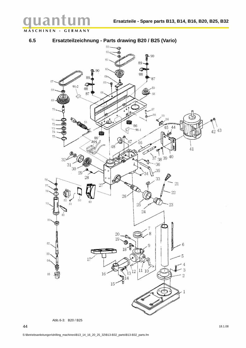
6.5 Ersatzteilzeichnung - Parts drawing B20 / B25 (Vario)
Abb.6-3: B20 / B25
44
S:\Betriebsanleitungen\drilling_machines\B13_14_16_20_25_32\B13-B32_parts\B13-B32_parts.fm
18.1.08
quantumM A S C H I N E N - G E R M A N Y
Ersatzteile - Spare parts B13, B14, B16, B20, B25, B32
6.6 Bohrfutterschutz B20, B25 - Drill chuck protection B20, B25
18.1.08
S:\Betriebsanleitung
202
201
203
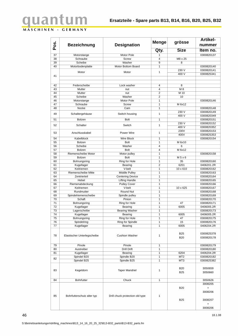
6.6.1 Ersatzteilliste - Parts list B20 / B25 (Vario)
Pos. Bezeichnung Designation Menge grösse Artikel-
nummerQty. Size Item no.
1 Maschinenfuss Base 1 0300820101
2 Säulenflansch 1B20 0300820102B25 0300825302
3 Scheibe Washer 4 03008201034 Schraube Screw 4 10 0300820104
5 Säule Column 1B20 0300820105B25 0300825305
6 Zahnstange Rack 1B20 0300820106B25 0300825306
7 Säulenring Colum Ring 1 03008201078 Bolzen Bolt 1 M 6x10⁹ Bohrtischhalter Support 1 030082010910 Kurbel Crank 1 030082011011 Schraube Screw 1 M 6x1512 Getriebewelle Gear Shaft 1 030082011214 Schraube Screw 1 M 6x1515 Klemmhebel Clamp Handle 1 030082011516 Arm Arm 1 030082011617 Bohrtisch Work Table 1 030082011718 Klemmhebel Clamp Handle 1 030082011819 Zahnrad Gear 1 030082011920 Schneckenrad Worm Gear 1 030082012021 Knopf Knob 3 030082012122 Hebel Lever 3 030082012223 Hebelsitz Lever Seat 1 030082012324 Bolzen Pin 1 5 x 32 030082012425 Skalenring Dial 1 030082012526 Ritzelwelle Pinion Shaft 1 030082012627 Gehäuse Case 1 030082012728 Bolzen Bolt 1 M10 x 1029 Mutter Nut 1 M 1030 Rückholfeder Turbination Spring 1 030082013031 Federgehäuse Cover of Spring 1 030082013132 Mutter Nut 2 M12x1,533 Schraube Screw 1 030082013334 Bolzen Bolt 2 M10 x 1035 Nockenwelle Camshaft 1 030082013536 Schraube Screw 1 0300820136
en\drilling_machines\B13_14_16_20_25_32\B13-B32_parts\B13-B32_parts.fm
45
Ersatzteile - Spare parts B13, B14, B16, B20, B25, B32quantumM A S C H I N E N - G E R M A N Y
46
S:\Betriebsanleitunge
37 Motorstange Motor Pole 1 030082013738 Schraube Screw 4 M8 x 2539 Scheibe Washer 9 840 Motorbodenplatte Motor Bottom Board 1 0300820140
41Motor Motor 1
230 V 0300820141400 V 0300825341
42 Federscheibe Lock washer 4 843 Mutter nut 4 M 844 Mutter nut 2 M 1045 Scheibe Washer 2 1046 Motorstange Motor Pole 1 030082014647 Schraube Screw 1 M 6x1248 Nocke Cam 1 0300820148
49 Schaltergehäuse Switch housing 1230 V 0300820149400 V 0300820349
51 Bolzen Bolt 1 0300820151
52 Schalter Switch 1230 V 0300820152400 V 0300820352
53 Anschlusskabel Power Wire 1230V 0300820153400V 0300825353
54 Kabelblock Wire Block 1 030082015455 Bolzen Bolt 1 M 6x1056 Scheibe Washer 4 657 Bolzen Bolt 4 M 6x1258 Riemenscheibe Motor Motor pulley 1 030082015859 Bolzen Bolt 1 M 5 x 660 Bohrungsring Ring for Hole 1 35 030082016061 Kugellager Bearing 2 6201 0406201.2R62 Keilriemen V-belt 1 10 x 610 030082016263 Riemenscheibe Mitte Middle Pulley 1 030082016364 Zentrierteil Centering Device 1 030082016465 Hebel Lifting Handle 1 030082016566 Riemenabdeckung Pulley Cover 1 030082016667 Keilriemen V-belt 1 10 x 625 030082016768 Rundmutter Round Nut 1 030082016869 Spindelriemenscheibe Spindle pulley 1 030082016970 Schaft Pinion 1 030082017071 Bohrungsring Ring for Hole 1 47 030082017172 Kugellager Bearing 1 6005 0406005.2R73 Lagerscheibe Bearing Washer 1 030082017374 Kugellager Bearing 1 6005 0406005.2R75 Bohrungsring Ring for Hole 1 47 030082017576 Spindelring Ring for Spindle 1 15 030082017677 Kugellager Bearing 1 6005 0406204.2R
78 Elastischer Unterlegscheibe Cushion Washer 1B25B20
03008253780300820178
79 Pinole Pinole 1 030082017980 Austreiber Drill Drift 1 030082018081 Kugellager Bearing 1 6204 0406204.2R
82Spindel B20 Spindle B20 1 MT2 0300820182Spindel B25 Spindle B25 1 MT3 0300825382
83 Kegeldorn Taper Mandriel 1B20B25
30506593050660
84 Bohrfutter Chuck 1 3050626
85 Bohrfutterschutz alter typ Drill chuck protection old type 1
B20
B25
3008205 +
3008206
3008207+
3008206
Pos. Bezeichnung Designation Menge grösse Artikel-
nummerQty. Size Item no.
n\drilling_machines\B13_14_16_20_25_32\B13-B32_parts\B13-B32_parts.fm
18.1.08
quantumM A S C H I N E N - G E R M A N Y
Ersatzteile - Spare parts B13, B14, B16, B20, B25, B32
18.1.08
S:\Betriebsanleitung
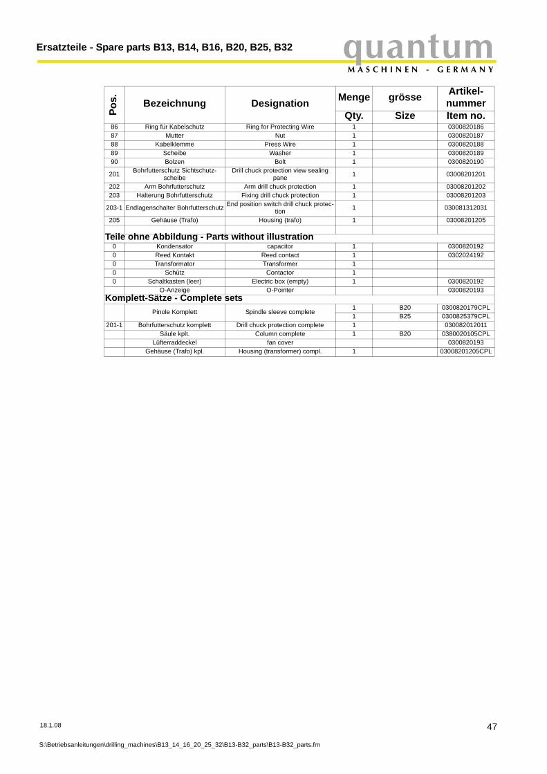
86 Ring für Kabelschutz Ring for Protecting Wire 1 030082018687 Mutter Nut 1 030082018788 Kabelklemme Press Wire 1 030082018889 Scheibe Washer 1 030082018990 Bolzen Bolt 1 0300820190
201 Bohrfutterschutz Sichtschutz-scheibe
Drill chuck protection view sealing pane 1 03008201201
202 Arm Bohrfutterschutz Arm drill chuck protection 1 03008201202203 Halterung Bohrfutterschutz Fixing drill chuck protection 1 03008201203
203-1 Endlagenschalter Bohrfutterschutz End position switch drill chuck protec-tion 1 030081312031
205 Gehäuse (Trafo) Housing (trafo) 1 03008201205
Teile ohne Abbildung - Parts without illustration0 Kondensator capacitor 1 03008201920 Reed Kontakt Reed contact 1 03020241920 Transformator Transformer 10 Schütz Contactor 10 Schaltkasten (leer) Electric box (empty) 1 0300820192
O-Anzeige O-Pointer 0300820193Komplett-Sätze - Complete sets
Pinole Komplett Spindle sleeve complete1 B20 0300820179CPL1 B25 0300825379CPL
201-1 Bohrfutterschutz komplett Drill chuck protection complete 1 030082012011Säule kplt. Column complete 1 B20 0380020105CPL
Lüfterraddeckel fan cover 0300820193Gehäuse (Trafo) kpl. Housing (transformer) compl. 1 03008201205CPL
Pos. Bezeichnung Designation Menge grösse Artikel-
nummerQty. Size Item no.
en\drilling_machines\B13_14_16_20_25_32\B13-B32_parts\B13-B32_parts.fm
47
Ersatzteile - Spare parts B13, B14, B16, B20, B25, B32quantumM A S C H I N E N - G E R M A N Y
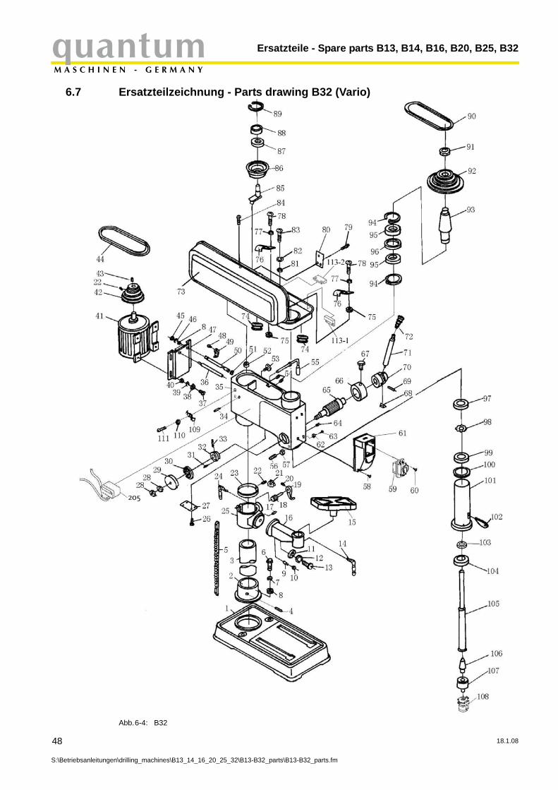
6.7 Ersatzteilzeichnung - Parts drawing B32 (Vario)
Abb.6-4: B32
48
S:\Betriebsanleitungen\drilling_machines\B13_14_16_20_25_32\B13-B32_parts\B13-B32_parts.fm
18.1.08
quantumM A S C H I N E N - G E R M A N Y
Ersatzteile - Spare parts B13, B14, B16, B20, B25, B32
6.8 Bohrfutterschutz B32 - Drill chuck protection B32
18.1.08
S:\Betriebsanleitung
202
201
203
6.8.1 Ersatzteilliste - Parts list B32 (Vario)
Pos. Bezeichnung Designation Menge grösse Artikelnum-
merQty. Size Item no.
1 Maschinenfuss Base 1 03008323012 Säulenflansch Column Seat 1 03008323023 Säule Column 1 03008323034 Arretierbolzen Lock Bolt 1 M 10x105 Zahnstange Rack 1 03008323056 Schraube Screw 5 M12 x 409 Bolzen (A) Pin (A) 1 030083230910 Mutter Nut 1 M614 Klemmhebel Clamp Handle 1 030083231415 Bohrtisch Work Table 1 030083231516 Arm Arm 1 030083231617 Bolzen Pin 1 030083231718 Schneckenrad Worm Wheel 1 030083231819 Kurbel Crank 1 030083231920 Schraube bolt 1 M 6 x 1221 Zahnrad Gear 1 030083232123 Säulenring Column Ring 1 030083232324 Klemmhebel Clamp Handle 1 030083232425 Bohrtischhalter Support 1 030083232526 Bolzen Bolt 4 M 5 x 827 Abdeckung Cover Board 1 030083232729 Federgehäuse Cover of Spring 1 030083232930 Rückholfeder Turbination Spring 1 030083233031 Federstift Spring Pin 1 6 x 2132 Federsitz Spring Seat 1 030083233233 Federstift Spring Pin 1 3 x 1534 Bolzen Bolt 1 M10 x 1235 Gehäuse Case 4 030083233536 Motorstange Motor Pole 4 030083233637 Schraube Screw 4 030083233738 Mutter Nut 4 M8
41Motor Motor 1 400 V 0300832341
42 Motorriemenscheibe Motor pulley 1 neuer typ / new type 030083234242 Motorriemenscheibe Motor pulley 1 alter typ / old type 032323843 Paßfeder Key 1 0300832343
44 Keilriemen V - belt 1neuer typ / new type
13 x 7500323274
en\drilling_machines\B13_14_16_20_25_32\B13-B32_parts\B13-B32_parts.fm
49
Ersatzteile - Spare parts B13, B14, B16, B20, B25, B32quantumM A S C H I N E N - G E R M A N Y
50
S:\Betriebsanleitunge
44 Keilriemen V - belt 1 15x740Li (old type) 032325945 Mutter Nut 2 030083234547 Motorbodenplatte Motor Bottom Board 1 030083234749 Nocke Cam 1 030083234950 Motorstange Motor Pole 1 030083235052 Gummidichtung Rubber Washer 1 030083235253 Bolzen (A) Bolt (A) 1 030083235354 Bolzen Bolt 1 030083235455 Nockenwelle Cam Shaft 1 030083235556 Bolzen Bolt 1 030083235657 Mutter Nut 1 M1058 Bolzen Bolt 4 030083235859 Schalter Switch 1 030082035260 Bolzen Bolt 3 030083236061 Schaltergehäuse Switch Housing 1 030083236162 Zeiger Pointer 1 030083236263 Bolzen Bolt 1 030083236364 Bolzen Bolt 1 030083236465 Schaftritzel Pinion Shaft 2 030083236566 Skalenring Dial 1 030083236667 Bolzen (B) Bolt (B) 1 40 030083236768 Klemmstück Clamping Piece 1 030083236869 Federstift Spring Pin 1 6 030083236970 Hebelsitz Lever Seat 1 030083237071 Hebel Lever 3 030083237172 Knopf Knob 3 030083237273 Riemengehäuse Pulley Cover 1 030083237374 Schutz Kabelring Protect Wire Ring 2 030083237475 Mutter Nut 2 030083237576 Druckkabelblock Press Wire Block 2 030083237677 Scheibe Washer 2 030083237778 Bolzen Bolt 2 030083237879 Bolzen Bolt 1 M5x880 Quardatisches Bord Square Board 1 030083238081 Scheibe Washer 4 682 Federring Spring Washer 4 683 Bolzen Bolt 4 M6x1684 Bolzen Bolt 1 030083238485 Zentrierstück Centering Device 1 030083238586 Keilriemenscheibe Mitte Middle pulley 1 neuer typ / new type 030083238686 Keilriemenscheibe Mitte Middle pulley 1 alter typ / old type 032323587 Kugellager Bearing 1 0406202.2R89 Klammer Circlip 1 40 0300832389
90 Keilriemen V - belt 1gates Super HC MN SPA 832 (new type)
13 x 8500323273
90 Keilriemen V - belt 1 15x845Li (old type) 032325891 Mutter Nut 1 030083239192 Spindel-Keilriemenscheibe Spindle pulley 1 neuer typ / new type 030083239292 Spindel-Keilriemenscheibe Spindle pulley 1 alter typ / old type 032323793 Schaft Pinion 1 030083239394 Klammer Circlip 1 030083239495 Kugellager Bearing 1 627 040627.2R96 Ring Ring 1 030083239697 Rundmutter Round nut 1 030083239798 Scheibe Washer 1 030083239899 Kugellager Bearing 1 6206 0406206.2R
100 Scheibe Washer 1 03008323100101 Pinole Pinole 1 03008323101102 Austreiber Drill Drift 1 03008323102103 Kugellager Bearing 1 6007 0406007.2R104 Kugellager Bearing 1 6208-2Z 0406208.2R105 Spindel Spindle 1 03008323105106 Kegeldorn Taper Mandril 1 3050661107 Bohrfutter chuck 1 3050626
Pos. Bezeichnung Designation Menge grösse Artikelnum-
merQty. Size Item no.
n\drilling_machines\B13_14_16_20_25_32\B13-B32_parts\B13-B32_parts.fm
18.1.08
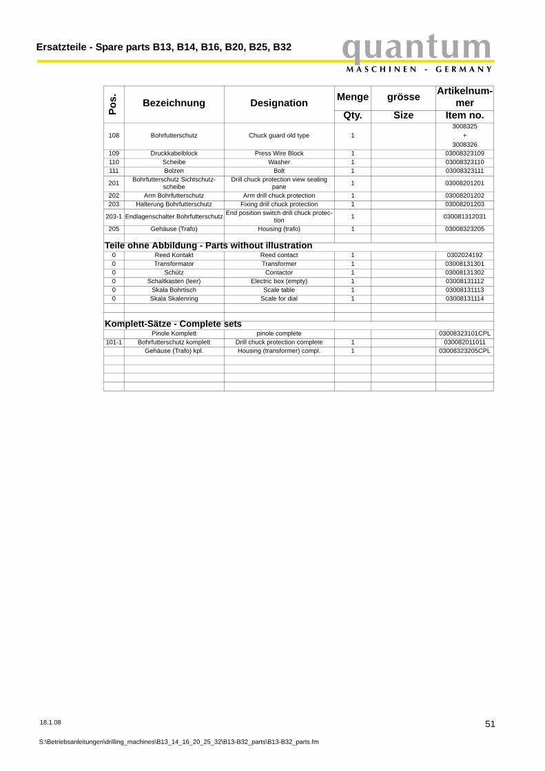
quantumM A S C H I N E N - G E R M A N Y
Ersatzteile - Spare parts B13, B14, B16, B20, B25, B32
18.1.08
S:\Betriebsanleitung
108 Bohrfutterschutz Chuck guard old type 13008325
+3008326
109 Druckkabelblock Press Wire Block 1 03008323109110 Scheibe Washer 1 03008323110111 Bolzen Bolt 1 03008323111
201 Bohrfutterschutz Sichtschutz-scheibe
Drill chuck protection view sealing pane 1 03008201201
202 Arm Bohrfutterschutz Arm drill chuck protection 1 03008201202203 Halterung Bohrfutterschutz Fixing drill chuck protection 1 03008201203
203-1 Endlagenschalter Bohrfutterschutz End position switch drill chuck protec-tion 1 030081312031
205 Gehäuse (Trafo) Housing (trafo) 1 03008323205
Teile ohne Abbildung - Parts without illustration0 Reed Kontakt Reed contact 1 03020241920 Transformator Transformer 1 030081313010 Schütz Contactor 1 030081313020 Schaltkasten (leer) Electric box (empty) 1 030081311120 Skala Bohrtisch Scale table 1 030081311130 Skala Skalenring Scale for dial 1 03008131114
Komplett-Sätze - Complete setsPinole Komplett pinole complete 03008323101CPL
101-1 Bohrfutterschutz komplett Drill chuck protection complete 1 030082011011Gehäuse (Trafo) kpl. Housing (transformer) compl. 1 03008323205CPL
Pos. Bezeichnung Designation Menge grösse Artikelnum-
merQty. Size Item no.
en\drilling_machines\B13_14_16_20_25_32\B13-B32_parts\B13-B32_parts.fm
51
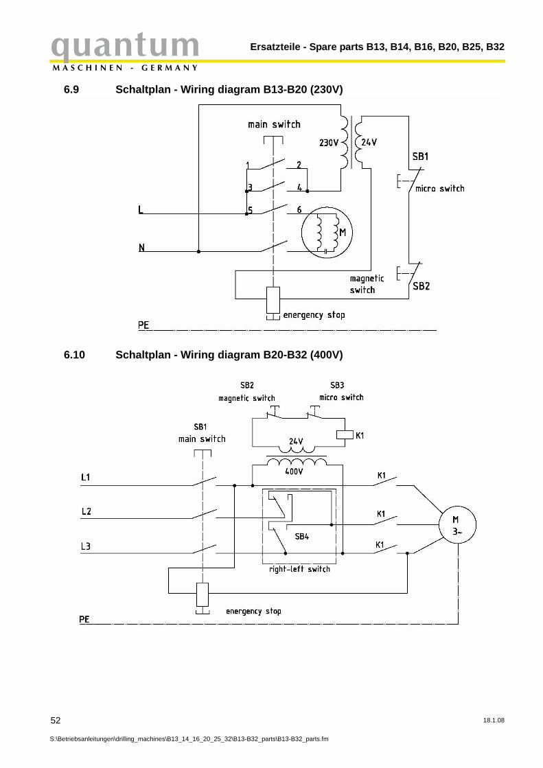
Ersatzteile - Spare parts B13, B14, B16, B20, B25, B32quantumM A S C H I N E N - G E R M A N Y
6.9 Schaltplan - Wiring diagram B13-B20 (230V)
6.10 Schaltplan - Wiring diagram B20-B32 (400V)
52
S:\Betriebsanleitungen\drilling_machines\B13_14_16_20_25_32\B13-B32_parts\B13-B32_parts.fm
18.1.08
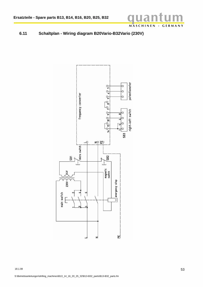
quantumM A S C H I N E N - G E R M A N Y
Ersatzteile - Spare parts B13, B14, B16, B20, B25, B32
6.11 Schaltplan - Wiring diagram B20Vario-B32Vario (230V)
18.1.08
S:\Betriebsanleitungen\drilling_machines\B13_14_16_20_25_32\B13-B32_parts\B13-B32_parts.fm
53
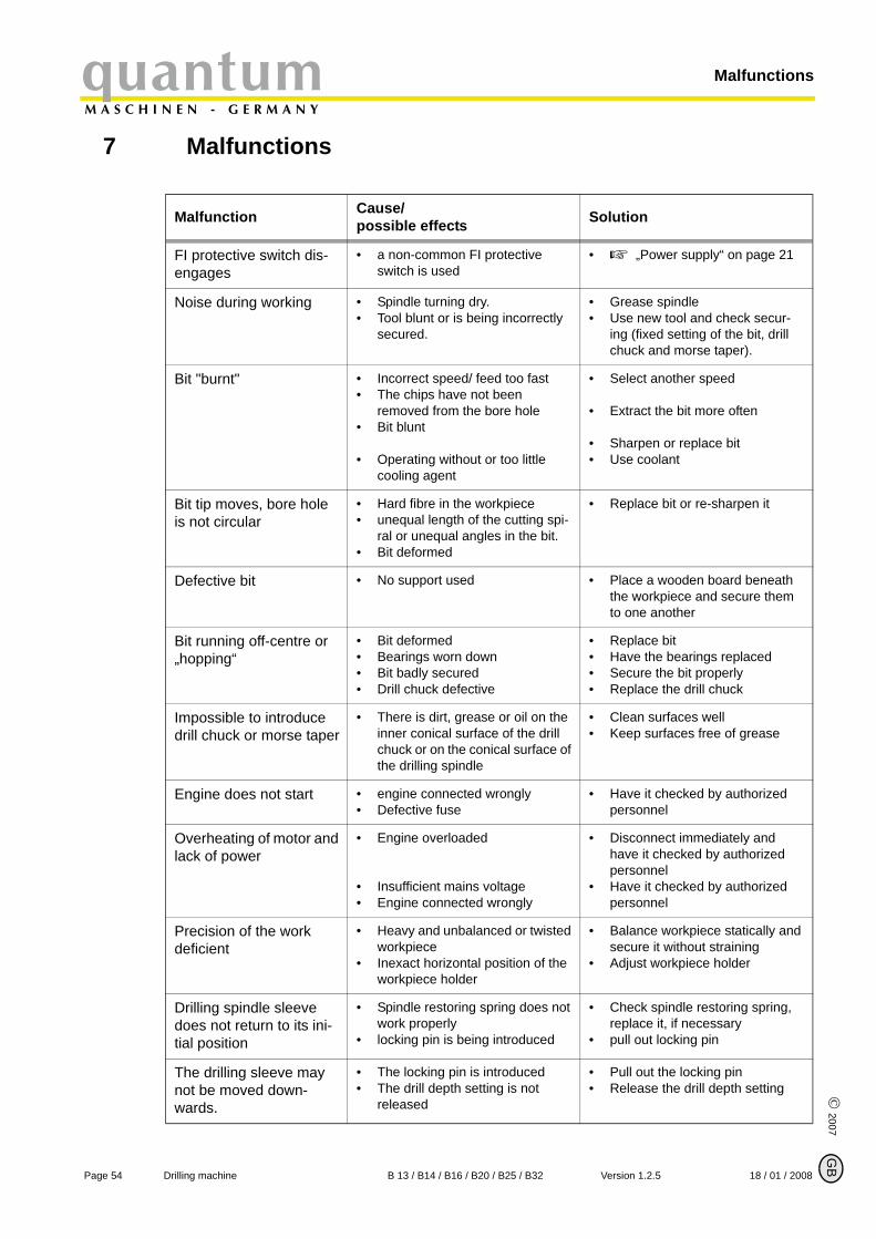
MalfunctionsquantumM A S C H I N E N - G E R M A N Y
© 2007
G
7 Malfunctions
Malfunction Cause/possible effects Solution
FI protective switch dis-engages
• a non-common FI protective switch is used
• „Power supply“ on page 21
Noise during working • Spindle turning dry.• Tool blunt or is being incorrectly
secured.
• Grease spindle• Use new tool and check secur-
ing (fixed setting of the bit, drill chuck and morse taper).
Bit "burnt" • Incorrect speed/ feed too fast• The chips have not been
removed from the bore hole• Bit blunt
• Operating without or too little cooling agent
• Select another speed
• Extract the bit more often
• Sharpen or replace bit• Use coolant
Bit tip moves, bore hole is not circular
• Hard fibre in the workpiece • unequal length of the cutting spi-
ral or unequal angles in the bit.• Bit deformed
• Replace bit or re-sharpen it
Defective bit • No support used • Place a wooden board beneath the workpiece and secure them to one another
Bit running off-centre or „hopping“
• Bit deformed• Bearings worn down• Bit badly secured• Drill chuck defective
• Replace bit• Have the bearings replaced• Secure the bit properly• Replace the drill chuck
Impossible to introduce drill chuck or morse taper
• There is dirt, grease or oil on the inner conical surface of the drill chuck or on the conical surface of the drilling spindle
• Clean surfaces well• Keep surfaces free of grease
Engine does not start • engine connected wrongly• Defective fuse
• Have it checked by authorized personnel
Overheating of motor and lack of power
• Engine overloaded
• Insufficient mains voltage• Engine connected wrongly
• Disconnect immediately and have it checked by authorized personnel
• Have it checked by authorized personnel
Precision of the work deficient
• Heavy and unbalanced or twisted workpiece
• Inexact horizontal position of the workpiece holder
• Balance workpiece statically and secure it without straining
• Adjust workpiece holder
Drilling spindle sleeve does not return to its ini-tial position
• Spindle restoring spring does not work properly
• locking pin is being introduced
• Check spindle restoring spring, replace it, if necessary
• pull out locking pin
The drilling sleeve may not be moved down-wards.
• The locking pin is introduced• The drill depth setting is not
released
• Pull out the locking pin• Release the drill depth setting
B
Page 54 Drilling machine B 13 / B14 / B16 / B20 / B25 / B32 Version 1.2.5 18 / 01 / 2008
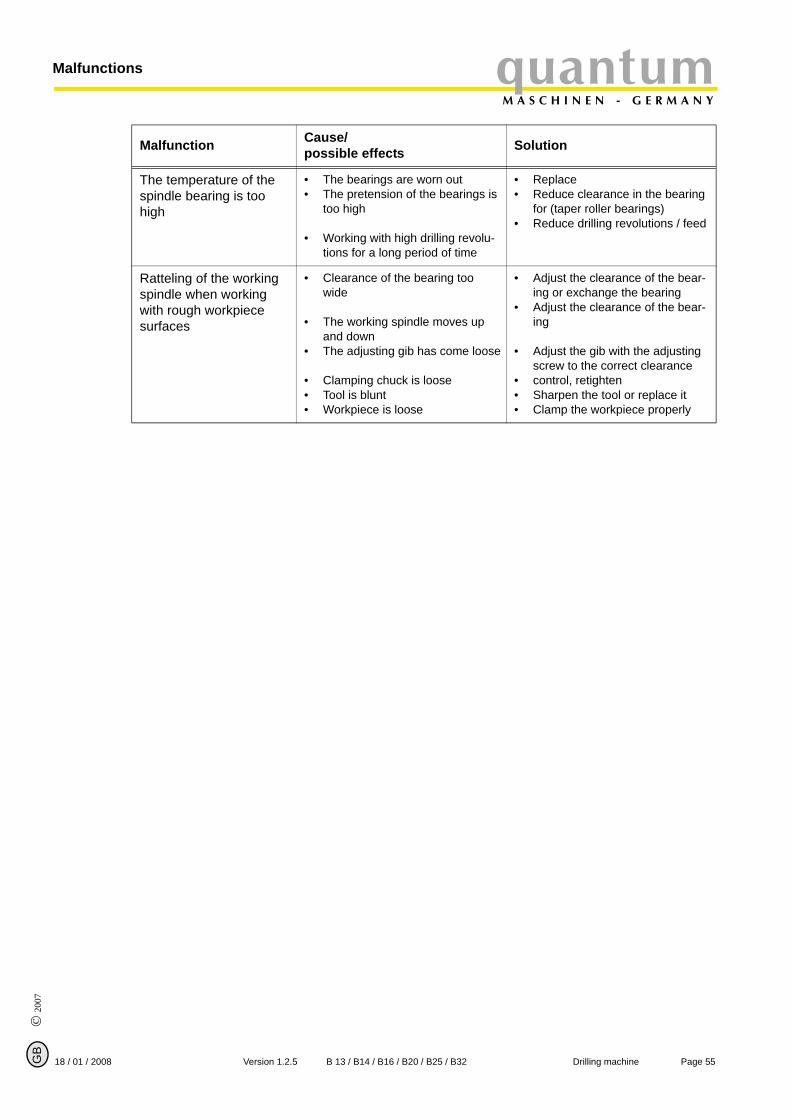
quantumM A S C H I N E N - G E R M A N Y
Malfunctions
© 2
007
GB
The temperature of the spindle bearing is too high
• The bearings are worn out• The pretension of the bearings is
too high
• Working with high drilling revolu-tions for a long period of time
• Replace• Reduce clearance in the bearing
for (taper roller bearings)• Reduce drilling revolutions / feed
Ratteling of the working spindle when working with rough workpiece surfaces
• Clearance of the bearing too wide
• The working spindle moves up and down
• The adjusting gib has come loose
• Clamping chuck is loose• Tool is blunt• Workpiece is loose
• Adjust the clearance of the bear-ing or exchange the bearing
• Adjust the clearance of the bear-ing
• Adjust the gib with the adjusting screw to the correct clearance
• control, retighten• Sharpen the tool or replace it• Clamp the workpiece properly
Malfunction Cause/possible effects Solution
Page 5518 / 01 / 2008 Version 1.2.5 B 13 / B14 / B16 / B20 / B25 / B32 Drilling machine
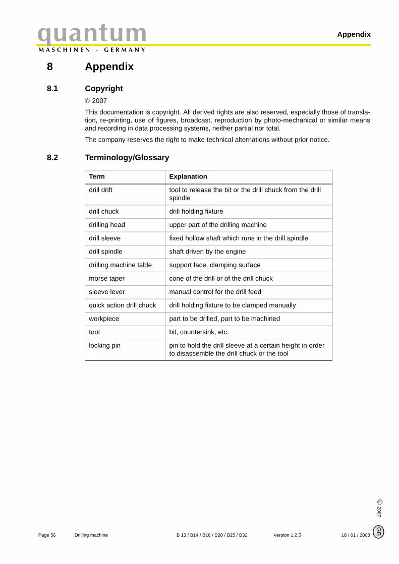
AppendixquantumM A S C H I N E N - G E R M A N Y
© 2007
G
8 Appendix
8.1 Copyright© 2007
This documentation is copyright. All derived rights are also reserved, especially those of transla-tion, re-printing, use of figures, broadcast, reproduction by photo-mechanical or similar meansand recording in data processing systems, neither partial nor total.
The company reserves the right to make technical alternations without prior notice.
8.2 Terminology/Glossary
Term Explanation
drill drift tool to release the bit or the drill chuck from the drill spindle
drill chuck drill holding fixture
drilling head upper part of the drilling machine
drill sleeve fixed hollow shaft which runs in the drill spindle
drill spindle shaft driven by the engine
drilling machine table support face, clamping surface
morse taper cone of the drill or of the drill chuck
sleeve lever manual control for the drill feed
quick action drill chuck drill holding fixture to be clamped manually
workpiece part to be drilled, part to be machined
tool bit, countersink, etc.
locking pin pin to hold the drill sleeve at a certain height in order to disassemble the drill chuck or the tool
B
Page 56 Drilling machine B 13 / B14 / B16 / B20 / B25 / B32 Version 1.2.5 18 / 01 / 2008

quantumM A S C H I N E N - G E R M A N Y
Appendix
© 2
007
GB
8.3 WarrantyWithin the term of warranty, the company Optimum warrants for a perfect quality of its productsand will reimburse any cost for overhaul or exchange of defective parts in case of constructionerror, fault in material and / or defect of fabrication.
The term of warranty for commercial use is 12 months and for use as an amateur it is 24months. Condition for a warranty claim due to construction errors, faults in material and / ordefects of fabrication is:
• Proof of purchase and that the instructions for use had been followed.In order to assert the claim of warranty, you have to present a typescript original receipt of purchase. It must comprise the complete address, date of purchase and type designation of the product.The instruction for use for the corresponding device as well as the safety information are to be observed. Damages due to operator’s mistakes may not be accepted as warranty claims.
• Correct use of the devices.The products of the company Optimum had been designed and built for certain purposes. They are listed in the operation manual.The warranty claim may not be accepted if the operating manual is not being followed pro-perly or if it is used for a purpose which has not been intended or with improper accessory.
• Maintenance work and cleaning.It is absolutely necessary to maintain and clean the machine in regular intervals according to the prescriptions of the instruction for use.By intervention of a third party, any warranty claim will expire. Maintenance work and cle-aning are usually not part of the claim of warranty.
• Original spare parts Make sure to use only original spare parts and original accessory. This can be acquired from authorized distributors of the machine.When other than original parts are being used, consequential damages may occur and dan-ger of accidents will increase. Disassembled or partially disassembled devices and devices which are repaired with foreign parts are excluded from warranty claims.
• Wearing partsCertain components are subject to wear out by time respectively a standard wear by use on the corresponding machine.Among these components are e.g. V-belts, ball bearings, switches, mains cables, gaskets and washers, etc. These wearing parts are not part of the warranty.
8.4 DisposalDisposal of used electric and electronic machines(Applicable in the countries of the European Union and other European countries with a sepa-rate collecting system for those devices).
The sign on the product or on its packing indicates that the product must not be handles as com-mon household waist, but that is needs to be delivered to a central collection point for recycling.Your contribution to the correct disposal of this product will protect the environment and thehealth of your fellow men. The environment and the health are endangered by incorrect dis-posal. Recycling of material will help to reduce the consumption of raw materials. Your DistrictOffice, the municipal waste collection station or the shop where you have bought the product willinform you about the recycling of this product.
8.5 RoHS , 2002/95/CEThe sign on the product or on its packing indicates that this product complies with the Europeanguideline 2002/95/EC .
Page 5718 / 01 / 2008 Version 1.2.5 B 13 / B14 / B16 / B20 / B25 / B32 Drilling machine
AppendixquantumM A S C H I N E N - G E R M A N Y
© 2007
G
8.6 Product follow-upWe are required to perform a follow-up service for our products which extends beyond shipment.
We would be grateful if you could send us the following information:
• modified settings• experiences with the drilling machine, which could be important for other users• recurring failures
Optimum Maschinen Germany GmbHDr.-Robert-Pfleger-Str. 26
D-96103 Hallstadt
Fax +49 (0) 951 - 96822 - 22E-Mail: [email protected]
B
Page 58 Drilling machine B 13 / B14 / B16 / B20 / B25 / B32 Version 1.2.5 18 / 01 / 2008
quantumM A S C H I N E N - G E R M A N Y
© 2
007
GB
8.7 EC - declaration of conformityThe manufacturer/retailer:
Optimum Maschinen Germany GmbHDr.-Robert-Pfleger-Str. 26D - 96103 Hallstadt
hereby declares that the following product,
type of machine: bench drill
pillar drill
designation of machine: B13, B14, B16, B20, B20 Vario, B25, B25 Vario, B32, B32 Vario
relevant EU directives:
machine directives 98/37/EG, Appendix II A
EMV- directive 89/336/EWG
low voltage directive 73/23/EWG
meets the provisions of the aforementioned directive, including any amendments valid at the time of this statement.
In order to ensure conformity, the following harmonized standard in particular have been applied:
EN 12717: 2001 Safety of machine tools, drilling machines
EN 62079 Editing of instructions - structure, content and illustra-tion (IEC 62079:2001)
Hallstadt, 18 / 01 / 2008
Kilian Stürmer(Manager)
Thomas Collrep(Manager)
Page 59Stand 18 / 01 / 2008 Version 1.2.5 B 13 / B14 / B16 / B20 / B25 / B32 Drilling machine
quantumM A S C H I N E N - G E R M A N Y
© 2007
GB
Page 60 Drilling machine B 13 / B14 / B16 / B20 / B25 / B32 Version 1.2.5 18 / 01 / 2008
Index
AAssembly ...................................................... 16, 17CCooling ......................................................... 32Copyright ...................................................... 56DDeclaration of conformity .............................. 59Dimensions ................................................... 15Drill chuck ..................................................... 32Drill depth stop ............................................. 24EEC - declaration of conformity ...................... 59Electric .......................................................... 13Environmental conditions ............................. 15Extent of supply ............................................ 16HHandling ....................................................... 23IInclination of the drilling machine table ........ 25Inspection ..................................................... 35Installation .................................................... 17Installation drawings ..................................... 20MMaintenance ................................................. 34Malfunctions ................................................. 54OON / OFF switch ........................................... 10PPower connection ......................................... 14Power supply ................................................ 21Product follow-up .......................................... 58Prohibition, warning and mandatory labels .. 11QQualification of employees ........................... 8SSafety devices .............................................. 9Speed alternation ......................................... 26Speed table .................................................. 27Spindle holding fixture .................................. 14Storage ......................................................... 17TTechnical Data ............................................. 14Transport ...................................................... 16UUser’s position .............................................. 9WWarning notes .............................................. 5Warranty ....................................................... 57