Embed Size (px)
Citation preview
MAS836 – Sensor Technologies for Interactive Environments
Original images © source unknown. All rights reserved. This content is excluded from our Creative Commons license. For more information, see http://ocw.mit.edu/fairuse.
Lecture 1 – Introduction and Analog Conditioning Electronics, Pt. 1
2
JAP2/04
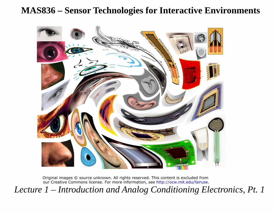
Expectations
• This is not has become a Lab class – …and does have an important lab component
• Class credit (12H) from: – Three or Four problem sets (30%)
• Copying not allowed • Credit not available after solutions handed out
– Final project (30%) – Lab Performance (30%) – Attendance/Participation/Reading (10%)
3
JAP2/04
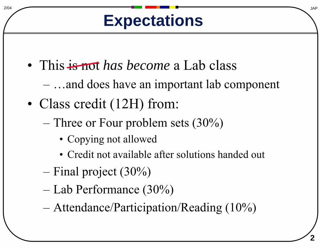
Projects
• “Project” should demonstrate skill integrating & applying sensors to make a meaningful and understood measurement – Final report required
• Justify sensor & design choice, quantify performance
• Class presentation in exam week – Short proposal needed
• Proposals will be quickly covered in class • We plan these to be due about a month before
project presentation
4
JAP2/04
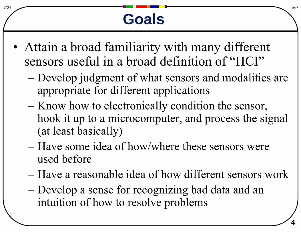
Goals
• Attain a broad familiarity with many different sensors useful in a broad definition of “HCI” – Develop judgment of what sensors and modalities are
appropriate for different applications – Know how to electronically condition the sensor,
hook it up to a microcomputer, and process the signal (at least basically)
– Have some idea of how/where these sensors were used before
– Have a reasonable idea of how different sensors work – Develop a sense for recognizing bad data and an
intuition of how to resolve problems
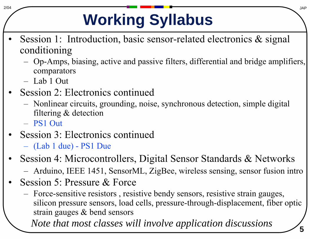
• Session 1: Introduction, basic sensor-related electronics & signal conditioning – Op-Amps, biasing, active and passive filters, differential and bridge amplifiers,
comparators – Lab 1 Out
• Session 2: Electronics continued – Nonlinear circuits, grounding, noise, synchronous detection, simple digital
filtering & detection – PS1 Out
• Session 3: Electronics continued – (Lab 1 due) - PS1 Due
• Session 4: Microcontrollers, Digital Sensor Standards & Networks – Arduino, IEEE 1451, SensorML, ZigBee, wireless sensing, sensor fusion intro
• Session 5: Pressure & Force – Force-sensitive resistors , resistive bendy sensors, resistive strain gauges,
silicon pressure sensors, load cells, pressure-through-displacement, fiber optic strain gauges & bend sensors
5
JAP2/04
Working Syllabus
Note that most classes will involve application discussions

• Session 6: Piezoelectrics and electroactive materials – Intro to ferroelectrics, crystals, PZT, PVDF, electronics, and signal
conditioning, electrostrictors and dielectric elastomers – Lab 2 due
• Session 7: Electric field and inductive sensing – Capacitive sensing modes and techniques, Hall sensors,
magnetostrictive sensors, metal detectors, LVDT's, VR Trackers, Wireless tag sensors
– PS2 Due / PS3 Out (Swap Lecture?) • Session 8: Optical sensing
– Devices (LDR's, solar cells, photodiodes, APD's, phototubes...), arrays, imagers, focal plane imaging/tracking, occultation, range by intensity of reflection, laser ranging (triangulation, phase slip, TOF)
– Lab 3 Due • Session 9: Inertial Systems
– Orientation sensors (compasses, ball-cup, bubble levels), gyroscopes, accelerometers, MEMs devices, IMU's, analysis techniques
– PS3 Due 6
JAP2/04
Working Syllabus (cont)
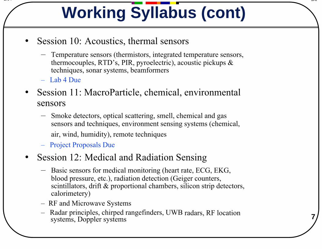
– Temperature sensors (thermistors, integrated temperature sensors, thermocouples, RTD’s, PIR, pyroelectric), acoustic pickups & techniques, sonar systems, beamformers
– Lab 4 Due
• Session 11: MacroParticle, chemical, environmental sensors – Smoke detectors, optical scattering, smell, chemical and gas
sensors and techniques, environment sensing systems (chemical, air, wind, humidity), remote techniques
– Project Proposals Due
• Session 12: Medical and Radiation Sensing – Basic sensors for medical monitoring (heart rate, ECG, EKG,
blood pressure, etc.), radiation detection (Geiger counters, scintillators, drift & proportional chambers, silicon strip detectors, calorimetery)
– RF and Microwave Systems – Radar principles, chirped rangefinders, UWB radars, RF location 7 systems, Doppler systems
JAP2/04
Working Syllabus (cont) • Session 10: Acoustics, thermal sensors
8
JAP2/04
Working Syllabus (cont)
• May X – Final Project Presentation
9
JAP2/04
Reference Sources
Covers of “AIP Handbook of Modern Sensors,” Jacob Fraden, “Sensors and Signal Conditioning,” Ramon Pallas-Areny and John G. Webster, and “The Alarm, Sensor, &
Security Cookbook,” Thomas Petruzzellis, removed due to copyright restrictions.
• Jacob Fraden – AIP Handbook of Modern Sensors, >2’nd Edition
• Ramon Pallas-Areny and John G. Webster – Sensors and Signal Conditioning, 2’nd Edition
• Thomas Petruzzellis (getting old…) – The Alarm, Sensor, & Security Cookbook
JAP2/04
Auxilary References (signals)
Covers for “Analog Signal Processing,” Ramon Pallas-Areny and John G. Webster, “The Art of Electronics,” Paul Horowitz and Winifield Hill, and “Active Filter Cookbook,”
Don Lancaster, removed due to copyright restrictions.
• Ramon Pallas-Areny & John G. Webster – Analog Signal Processing
• Paul Horowitz & Winifield Hill – The Art of Electronics
• Don Lancaster – Active Filter Cookbook
10
11
JAP2/04
Auxilary References
Covers of “The OpAmp Cookbook,” Walt Jung, “Intelligent Sensor Systems,” John Brignell and Neil White, and “Sensors for Mobile Robots: Theory and Application,” H.R.
Everett, removed due to copyright restrictions.
• Walt Jung – The OpAmp Cookbook
• John Brignell & Neil White – Intelligent Sensor Systems
• H.R. Everett – Sensors for Mobile Robots
JAP2/04
Good Niche References
Covers of “Capacitive Sensors: Design and Application,” Larry Baxter, “Piezoelectric Ceramics: Principles and Applications,” APC International, “Modern Inertial Technology:
Navigation, Guidance, and Control,” Anthony Lawrence, and “Electronic Distance Measurement: An Introduction,” J.M. Rueger, removed due to copyright restrictions.
• Larry Baxter – Capacitive Sensors
• APC International – Piezoelectric Ceramics: Principles & Applications
• Anthony Lawrence – Modern Inertial Technology
• J.M. Rueger – Electronic Distance Measurement 12
13
JAP2/04
Magazines
• Sensors Magazine - Free! • Circuit Cellar - Best EE-hacker magazine out • NASA Tech Briefs - Free! • Test and Measurement - Free! • IEEE Sensors Journal
Covers of Sensors Magazine, Circuit Cellar, NASA Tech Briefs, Test and Measurement, and IEEE Sensors Journal removed due to copyright restrictions.

14
JAP2/04
Conferences
• Sensors Expo – Big trade show with tutorials and proceedings
• IEEE Sensors Conference – Very large new state-of-the-art sensors conference
• SPIE – Old standby conference for sensors & applications
• Transducers – Emphasizes MEMs, but like IEEE Sensors
• UIST – ACM conference on user interface technology
• Sensys, IPSN/SPOTS, etc. – Sensor net conferences - not sensors…
15
JAP2/04
Websites
• http://www.sensorsportal.com/ – References, hints, sources
• http://www.sensorsmag.com/ Screenshot of “SensorsPortal” removed due to copyright restrictions.
– Sensors Magazine site • Buyers guide, Archive articles
• http://www.cs.cmu.edu/~chuck/robotpg/robofaq/10.html – Robotics sites often list sensor vendors, hints
• http://www.billbuxton.com/InputSources.html – Bill Buxton’s encyclopedia on input devices
16
JAP2/04
Hacker Websites
The following websites offer useful hacking gear, techniques, and ideas:
• instructables.com • hackaday.com • diylive.net • diyaudioprojects.com • bunniestudios.com/blog • epanorama.net • hackedgadgets.com • evilmadscientist.com
17
JAP2/04
Some Classic Sensor Module Sources
• http://www.parallax.com/ • http://www.sparkfun.com/ • http://www.ramseyelectronics.com/ • http://www.adafruit.com/
18
JAP2/04
Basic Sources for Electronics Digikey - www.digikey.com Mouser - www.mouser.com
Newark Allied
Hosfelt Electronics JameCo
Mat Electronics JDR
All Electronics Radio Shack (mainly online now)
19
JAP2/04
Today’s Assignment
Reading Assignment #1 (electronics)
• Read Fraden, Chapters 1&2 and Chapter 4 – His introduction & signal conditioning sections
• If you have Horowitz and Hill, go through Chapters 4 and 7 – Op Amps
• If you have Pallas-Areny, glance through Chapter 3 – Signal conditioning for resistive sensors

20
JAP2/04
The Age of the Sensor…
• Interaction revolution underway - possibilities exploding – Small, low-cost sensors easily available to measure nearly
everything… – Moore’s Law makes processors capable of meaningfully
exploiting the data in real time. – Low barriers to entry - easy to try things
• Deaf and blind computers... • We don’t really know what will really come after keyboard and mouse… • You can’t realize your vision for the future of interactivity by buying a
card and plugging it in...
– Sensors are permeating everything - interactivity everywhere • From toys to automobiles to smart homes
– From Burglar alarms to Ubiquitous Computing
JAP2/04
Sensing as Commodity
• Sensors are now becoming a commodity, and soon can easily be designed into most any device.
– Rather than omitting them from a cost/complexity viewpoint, it begins to make more sense to just include them if there’s any suspicion that they could be needed.
– This causes a shift in how sensors are used – rather than rely on only 1 or 2 sensors made a priori to measure particular quantities, many sensors will be used that don’t necessarily exactly measure the quantity of interest (especially as applications will become more general and evolve over time).
21
22
JAP2/04
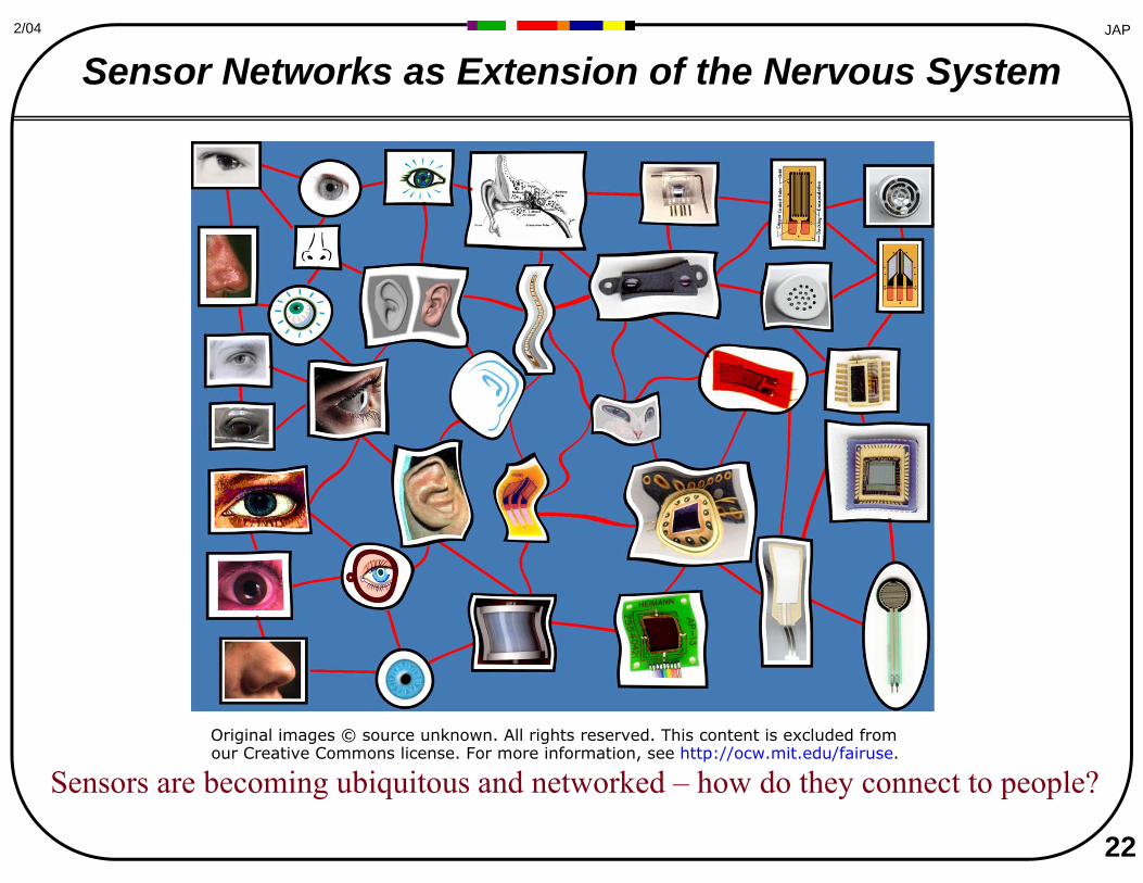
Sensor Networks as Extension of the Nervous System
Sensors are becoming ubiquitous and networked – how do they connect to people? Original images © source unknown. All rights reserved. This content is excluded from our Creative Commons license. For more information, see http://ocw.mit.edu/fairuse.
23
JAP2/04
Origins
• This class is a proper expansion of the pair of lectures on electronics and sensors that I give in MAS863, “How to Make (Almost) Anything” – Even so, “sensors” is a vast and general field – Any one lecture here can become least an entire course
elsewhere at MIT – You won’t become an expert
• Although you will be able to wander into a restaurant in sensorland and order a meal from the menu
• Use physics and constraints to couple a measured quantity into an unknown – Temperature can infer wind velocity (heat loss) – Displacement can infer:
• Pressure (with an elastomer or spring: F = kx) • Volume of fluid in a tank (V = Ah) • Velocity (2 measurements at different times: v = dx/dt) • Temperature (thermometer level) • Angle from vertical (displacement of a bubble)
– Measurements are used with a mathematical model to derive other parameters
• Estimation and Kalman Filtering, etc. 24
JAP2/04
Trading Modality • Sensor modes are intrinsically synaesthetic
– Not covered here...
25
JAP2/04
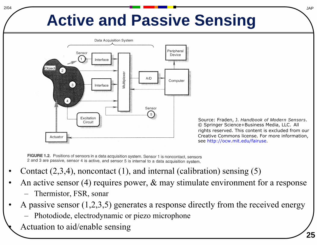
Active and Passive Sensing
• Contact (2,3,4), noncontact (1), and internal (calibration) sensing (5) • An active sensor (4) requires power, & may stimulate environment for a response
– Thermistor, FSR, sonar • A passive sensor (1,2,3,5) generates a response directly from the received energy
– Photodiode, electrodynamic or piezo microphone • Actuation to aid/enable sensing
Source: Fraden, J. Handbook of Modern Sensors. © Springer Science+Business Media, LLC. All rights reserved. This content is excluded from our Creative Commons license. For more information, see http://ocw.mit.edu/fairuse.
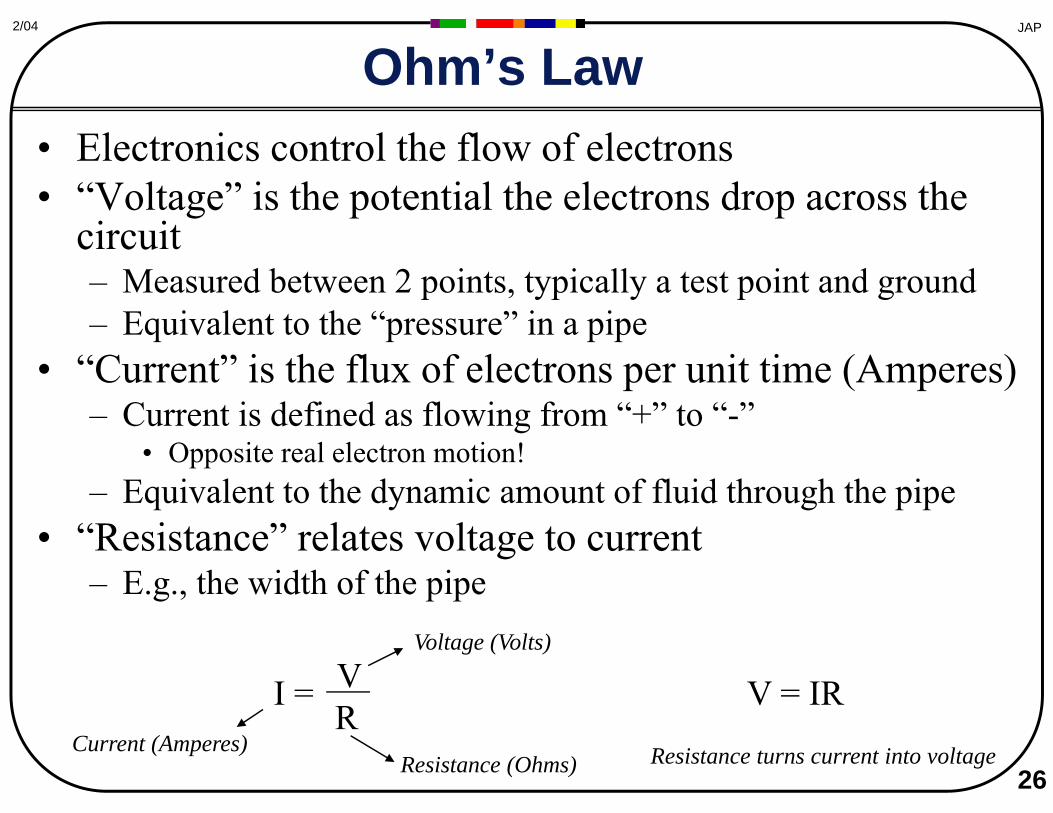
• Electronics control the flow of electrons • “Voltage” is the potential the electrons drop across the
circuit – Measured between 2 points, typically a test point and ground – Equivalent to the “pressure” in a pipe
• “Current” is the flux of electrons per unit time (Amperes) – Current is defined as flowing from “+” to “-”
• Opposite real electron motion! – Equivalent to the dynamic amount of fluid through the pipe
• “Resistance” relates voltage to current – E.g., the width of the pipe
V I = R
Voltage (Volts)
Current (Amperes) Resistance (Ohms)
V = IR
Resistance turns current into voltage 26
JAP2/04
Ohm’s Law
27
JAP2/04
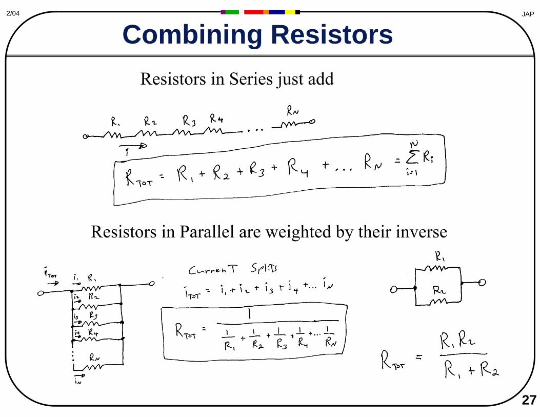
Combining Resistors Resistors in Series just add
Resistors in Parallel are weighted by their inverse
28
JAP2/04
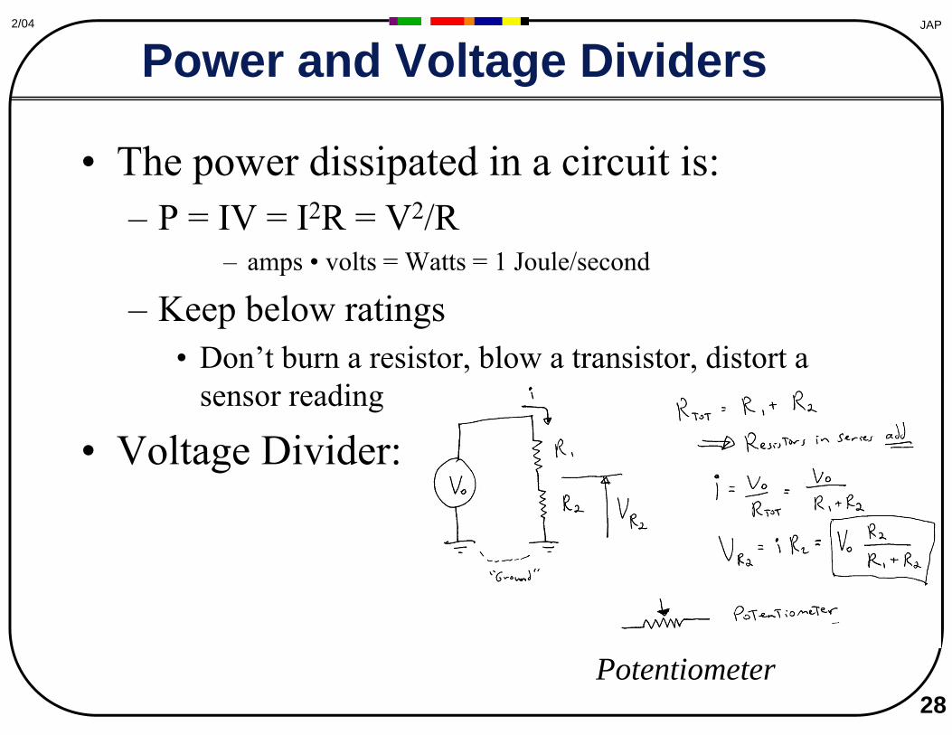
Power and Voltage Dividers
• The power dissipated in a circuit is: – P = IV = I2R = V2/R
– amps • volts = Watts = 1 Joule/second
– Keep below ratings • Don’t burn a resistor, blow a transistor, distort a
sensor reading
• Voltage Divider:
Potentiometer
29
JAP2/04
Signal Conditioning
conversion, gain, detection, filtering, discrimination...
Sensor Interface circuit
Zout
Vs
ZinV
Sensor Interface circuit
ZoutZin
I
Is
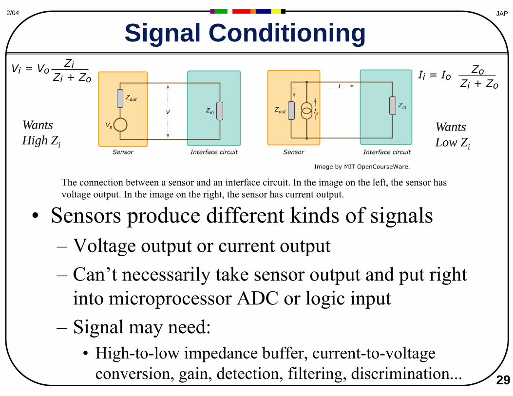
The connection between a sensor and an interface circuit. In the image on the left, the sensor has voltage output. In the image on the right, the sensor has current output.
• Sensors produce different kinds of signals– Voltage output or current output– Can’t necessarily take sensor output and put right
into microprocessor ADC or logic input– Signal may need:
• High-to-low impedance buffer, current-to-voltage
ZVi = V ioZi + Zo Ii = I oo
Zi + Zo Z
WantsHigh Zi
WantsLow Zi
Image by MIT OpenCourseWare.
30
JAP2/04
Transistors
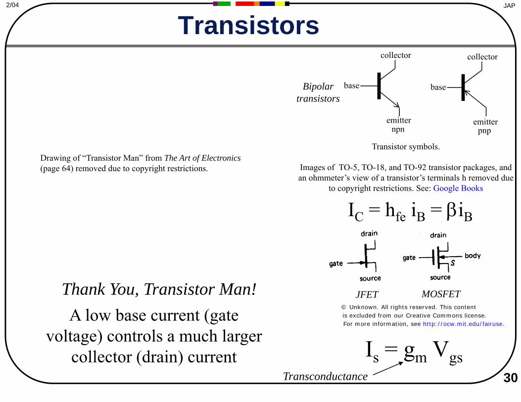
IC = hfe iB = βiB
Is = gm Vgs
JFET MOSFET
Transconductance
Bipolar transistors
collector
base
emitter
collector
base
emitter npn pnp
Transistor symbols.
Images of TO-5, TO-18, and TO-92 transistor packages, and an ohmmeter’s view of a transistor’s terminals h removed due
to copyright restrictions. See: Google Books
Drawing of “Transistor Man” from The Art of Electronics (page 64) removed due to copyright restrictions.
Thank You, Transistor Man! A low base current (gate
voltage) controls a much larger collector (drain) current
© Unknown. All rights reserved. This contentis excluded from our Creative Commons license. For more information, see http://ocw.mit.edu/fairuse.
JAP2/04
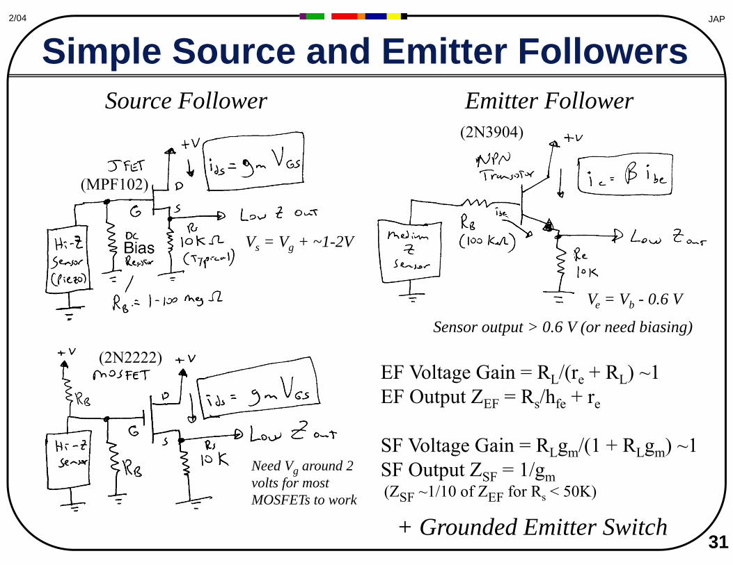
Simple Source and Emitter Followers Source Follower Emitter Follower
Vs = Vg + ~1-2V
Need Vg around 2 volts for most MOSFETs to work
Ve = Vb - 0.6 V
(MPF102)
(2N2222)
(2N3904)
Sensor output > 0.6 V (or need biasing)
EF Voltage Gain = RL/(re + RL) ~1 EF Output ZEF = Rs/hfe + re
SF Voltage Gain = RLgm/(1 + RLgm) ~1 SF Output ZSF = 1/gm (ZSF ~1/10 of ZEF for Rs < 50K)
+ Grounded Emitter Switch 31
JAP2/04
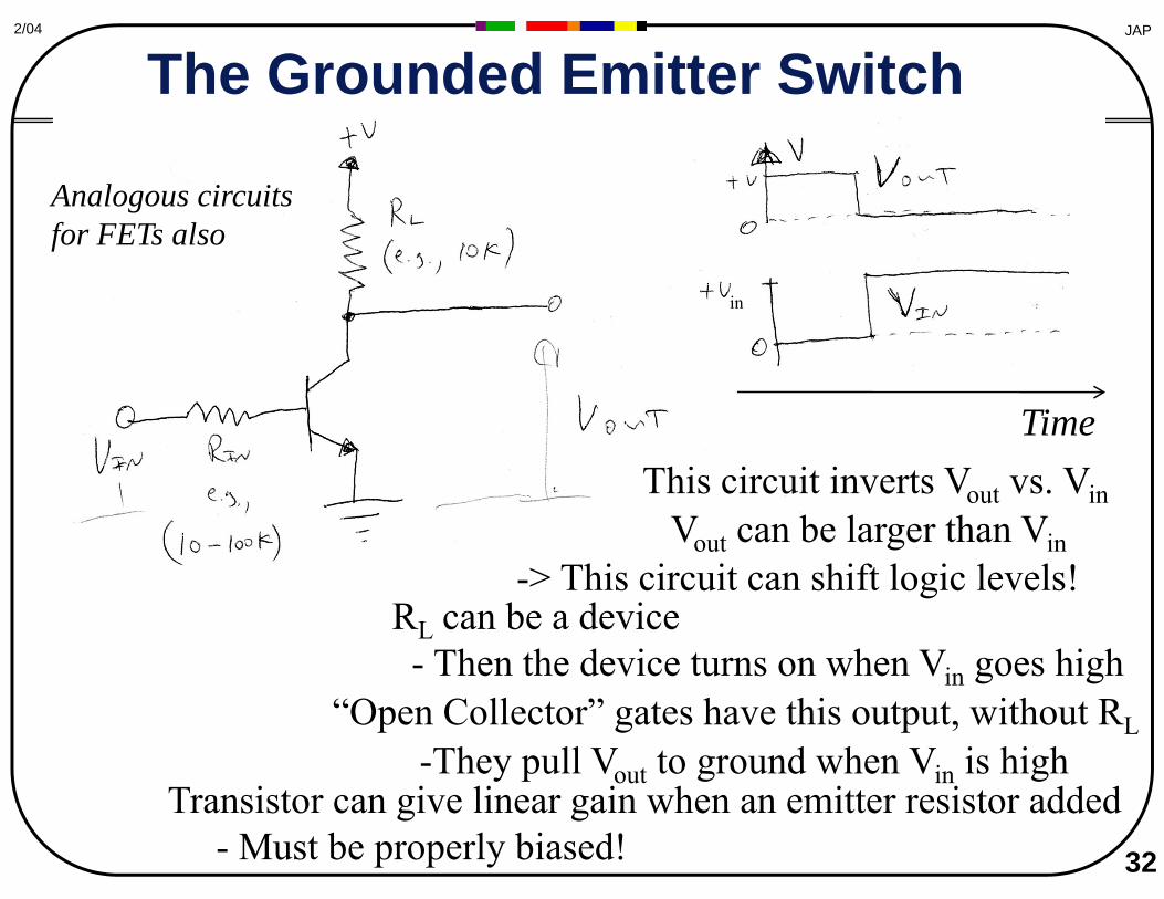
The Grounded Emitter Switch
Time
in
This circuit inverts Vout vs. Vin Vout can be larger than Vin
s circuit can shift logic levels! -> ThiRL can be a device
- Then the device turns on when Vin goes high “Open Collector” gates have this output, without RL
-They pull Vout to ground when Vin is highTransistor can give linear gain when an emitter resistor added
- Must be properly biased! 32
Analogous circuits for FETs also
33
JAP2/04
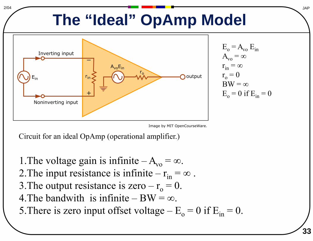
The “Ideal” OpAmp Model
Circuit for an ideal OpAmp (operational amplifier.)
1.The voltage gain is infinite – Avo = ∞. 2.The input resistance is infinite – rin = ∞ . 3.The output resistance is zero – ro = 0. 4.The bandwith is infinite – BW = ∞. 5.There is zero input offset voltage – Eo = 0 if Ein = 0.
Eo = Avo Ein Avo = ∞ rin = ∞ ro = 0 BW = ∞ Eo = 0 if Ein = 0
Ein
AvoEin
rin
ro
Noninverting input
Inverting input _
+
output
Image by MIT OpenCourseWare.
34
JAP2/04
Ideal OpAmp Possibilities
• No current flows into the input pins – Ideal behavior dictated by external components and
signal sources – Comparator
• Get a 1-bit digital trigger from an analog signal – Comparator with Hysteresis
• Build in deadband for noise
• With negative feedback, current flows through feedback resistor to make V+ equal to V– Ignores stability issues, bandwidth, and parasitics...
JAP2/04
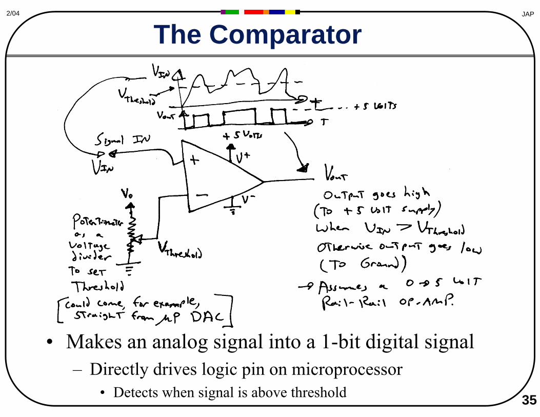
The Comparator
• Makes an analog signal into a 1-bit digital signal – Directly drives logic pin on microprocessor
• Detects when signal is above threshold 35
JAP2/04
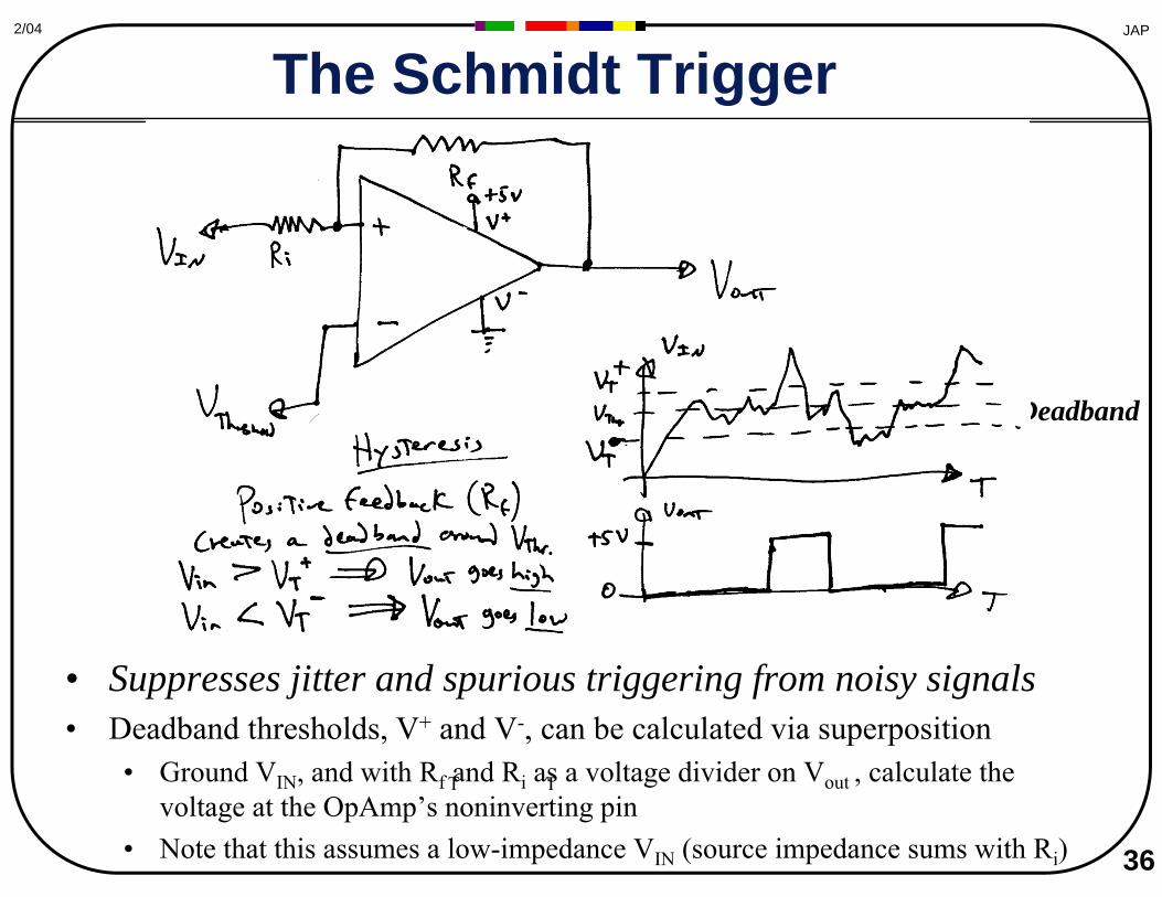
The Schmidt Trigger
• Suppresses jitter and spurious triggering from noisy signals • Deadband thresholds, V+ and V-, can be calculated via superposition
• Ground VIN, and with Rf T and Ri as a voltage T divider on Vout , calculate the voltage at the OpAmp’s noninverting pin
• Note that this assumes a low-impedance VIN (source impedance sums with Ri) 36
Deadband
37
JAP2/04
Negative Feedback
• Transimpedance Amplifier • Voltage Follower • Non-Inverting Amplifier • Inverting Amplifier • Inverting Summer
JAP2/04
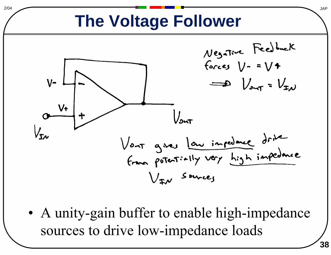
The Voltage Follower
• A unity-gain buffer to enable high-impedance sources to drive low-impedance loads
38
39
JAP2/04
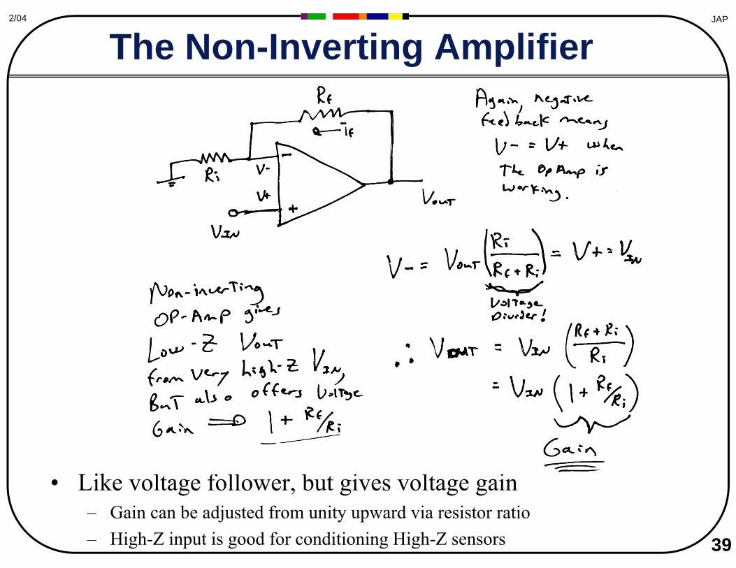
The Non-Inverting Amplifier
• Like voltage follower, but gives voltage gain – Gain can be adjusted from unity upward via resistor ratio – High-Z input is good for conditioning High-Z sensors
JAP2/04
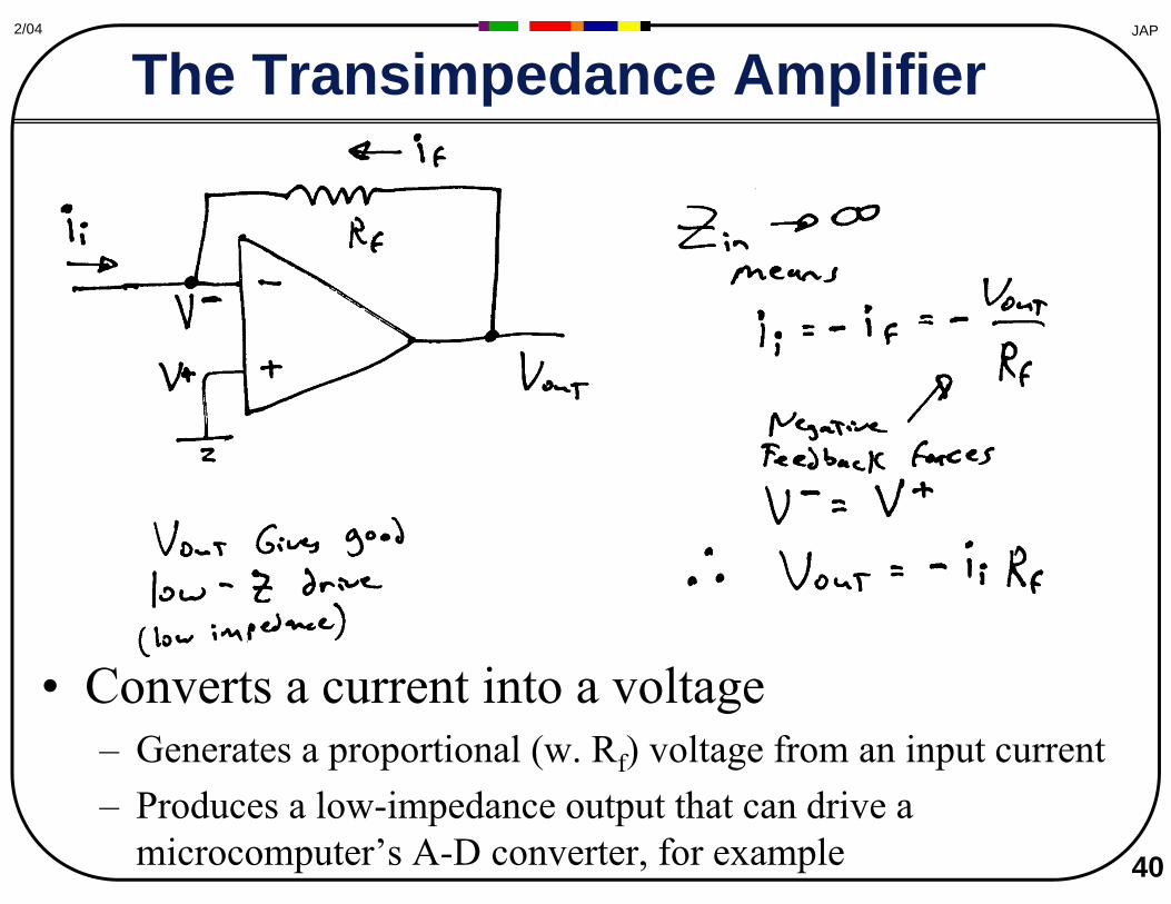
The Transimpedance Amplifier
• Converts a current into a voltage – Generates a proportional (w. Rf) voltage from an input current – Produces a low-impedance output that can drive a
microcomputer’s A-D converter, for example 40
41
JAP2/04
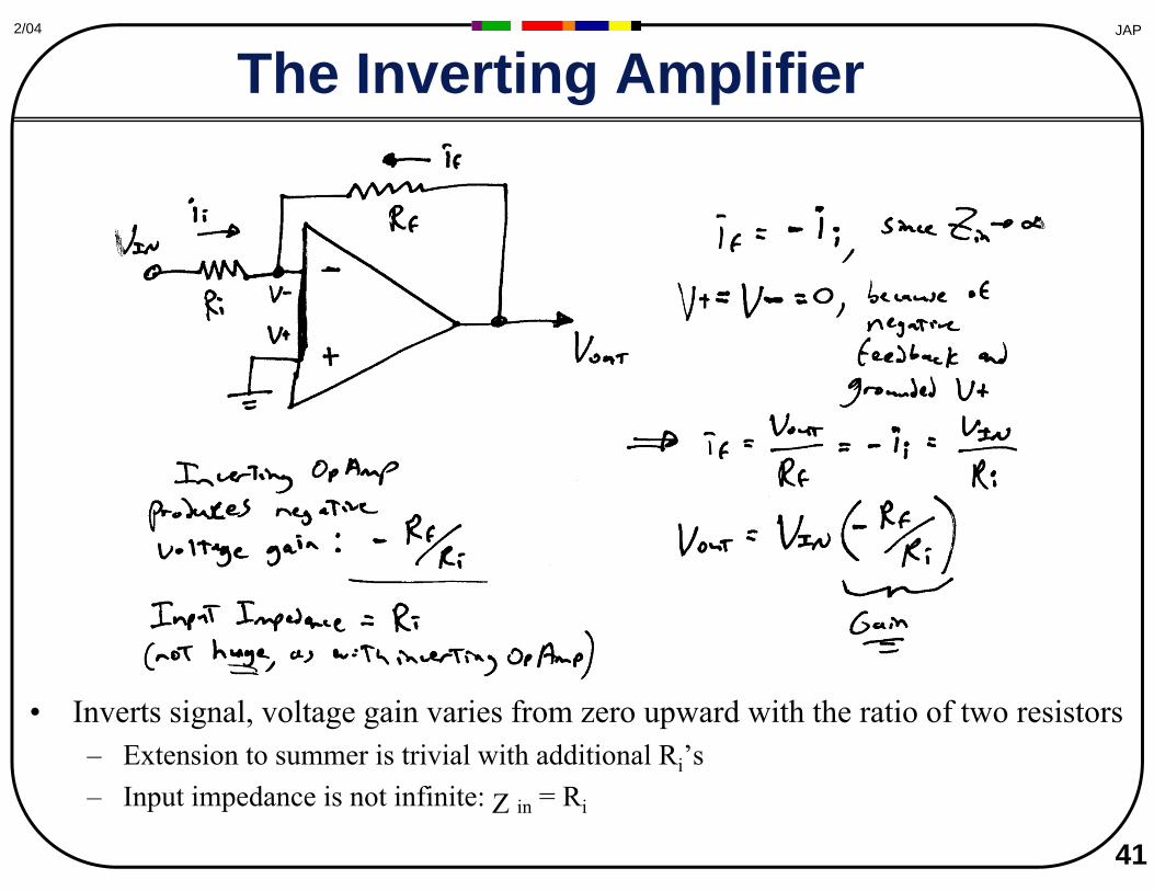
The Inverting Amplifier
• Inverts signal, voltage gain varies from zero upward with the ratio of two resistors – Extension to summer is trivial with additional Ri’s – Input impedance is not infinite: Z in = Ri
42
JAP2/04
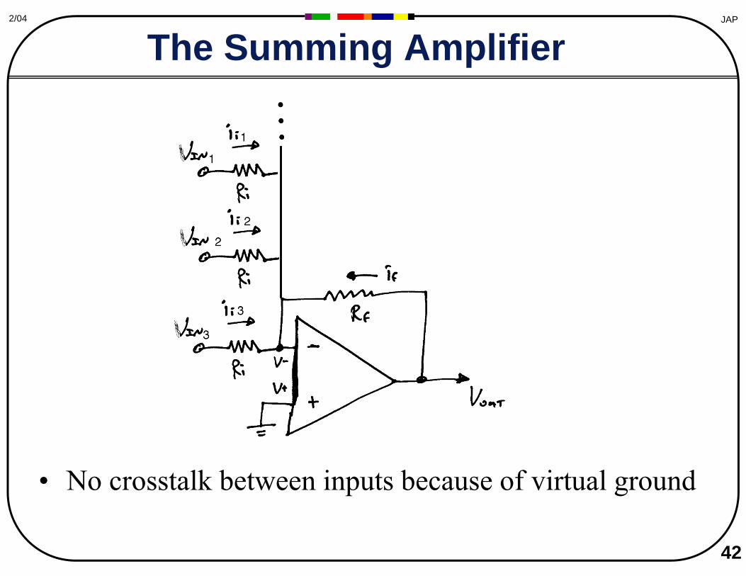
he Summing Amplifier T
• No crosstalk between inputs because of virtual ground
43
JAP2/04
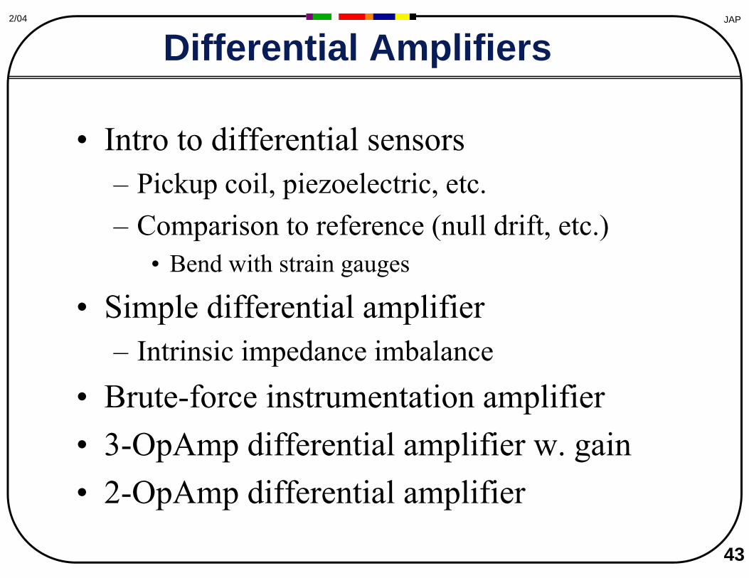
Differential Amplifiers
• Intro to differential sensors – Pickup coil, piezoelectric, etc. – Comparison to reference (null drift, etc.)
• Bend with strain gauges
• Simple differential amplifier – Intrinsic impedance imbalance
• Brute-force instrumentation amplifier • 3-OpAmp differential amplifier w. gain • 2-OpAmp differential amplifier
JAP2/04
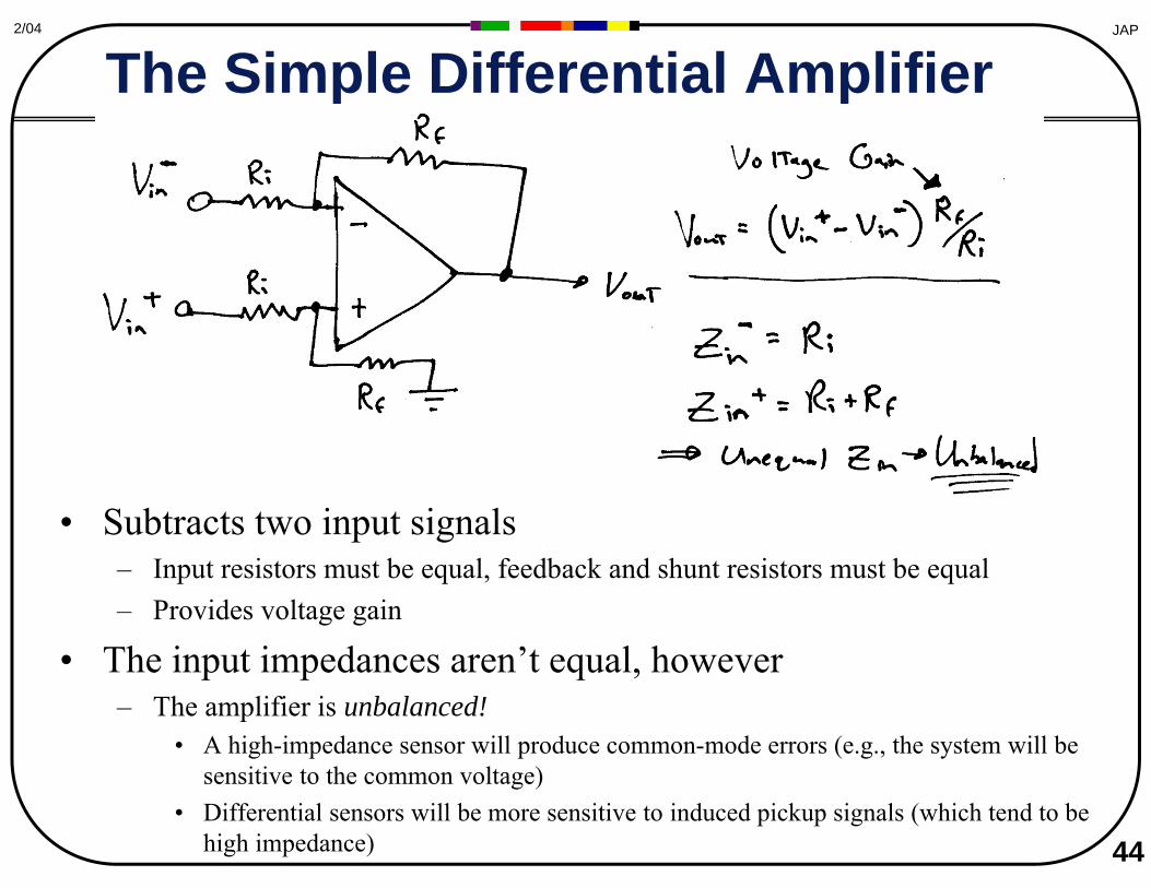
The Simple Differential Amplifier
• Subtracts two input signals – Input resistors must be equal, feedback and shunt resistors must be equal – Provides voltage gain
• The input impedances aren’t equal, however – The amplifier is unbalanced!
• A high-impedance sensor will produce common-mode errors (e.g., the system will be sensitive to the common voltage)
• Differential sensors will be more sensitive to induced pickup signals (which tend to be high impedance) 44
JAP2/04
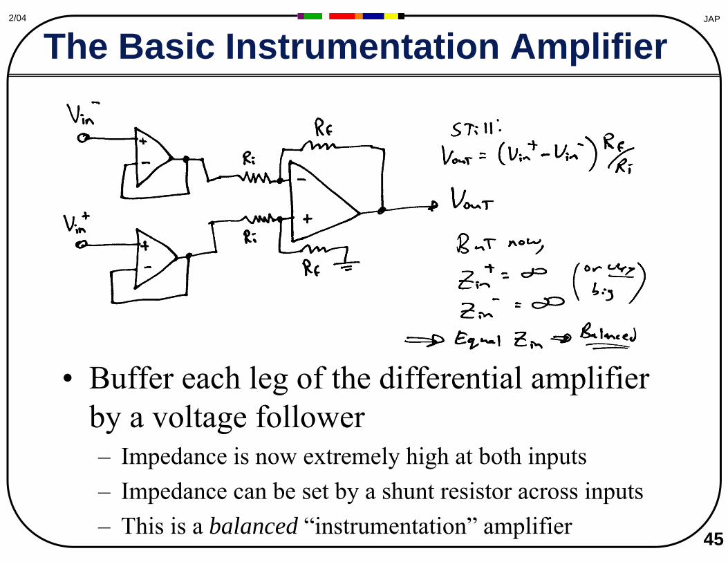
The Basic Instrumentation Amplifier
• Buffer each leg of the differential amplifier by a voltage follower – Impedance is now extremely high at both inputs – Impedance can be set by a shunt resistor across inputs – This is a balanced “instrumentation” amplifier 45

JAP2/04
The Three-OpAmp Instrumentation Amplifier
• Gain is varied by changing only one resistor, R1 – No need to re-trim other components for a gain change – Gain at first stages is better for signal/noise – This is the instrumentation amplifier of choice 46
JAP2/04
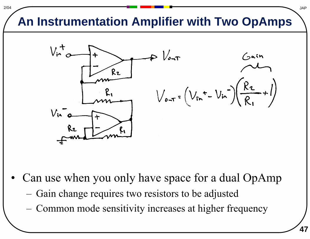
An Instrumentation Amplifier with Two OpAmps
• Can use when you only have space for a dual OpAmp – Gain change requires two resistors to be adjusted – Common mode sensitivity increases at higher frequency
47
JAP2/04
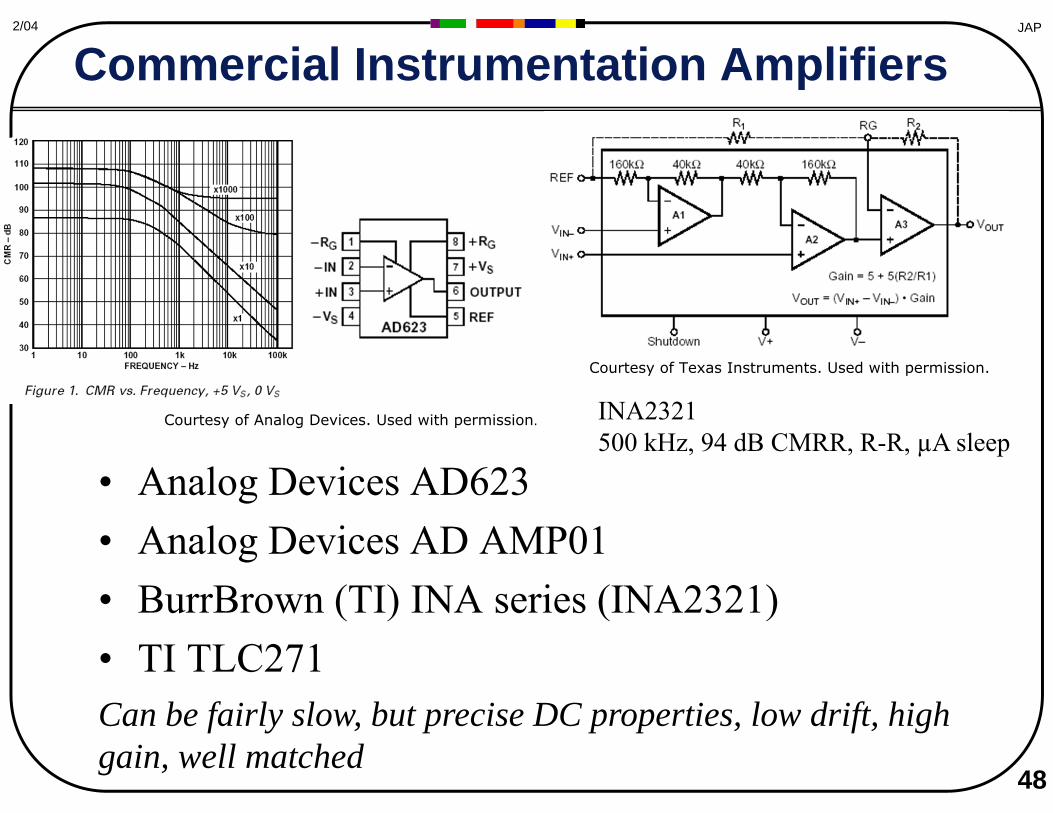
Commercial Instrumentation Amplifiers
• Analog Devices AD623 • Analog Devices AD AMP01 • BurrBrown (TI) INA series (INA2321) • TI TLC271 Can be fairly slow, but precise DC properties, low drift, high gain, well matched
48
INA2321 500 kHz, 94 dB CMRR, R-R, µA sleep
Courtesy of Texas Instruments. Used with permission.
Courtesy of Analog Devices. Used with permission.

49
JAP2/04
The Wheatstone Bridge
κ = R4/R1
• Bridge Conditioning • Active Bridge Servo’ing to keep null
Differential readout of a resistive sensor R3 = Resistive Sensor
Graph of the sensitivity of a disbalanced bridge as a function of impedance ratiofrom Handbook of Modern Sensors removed due to copyright restrictions. See: page 217 on Google Books.
© Unknown. All rights reserved. This content is excluded from our Creative Commons license. For more information, see http://ocw.mit.edu/fairuse.
50
JA
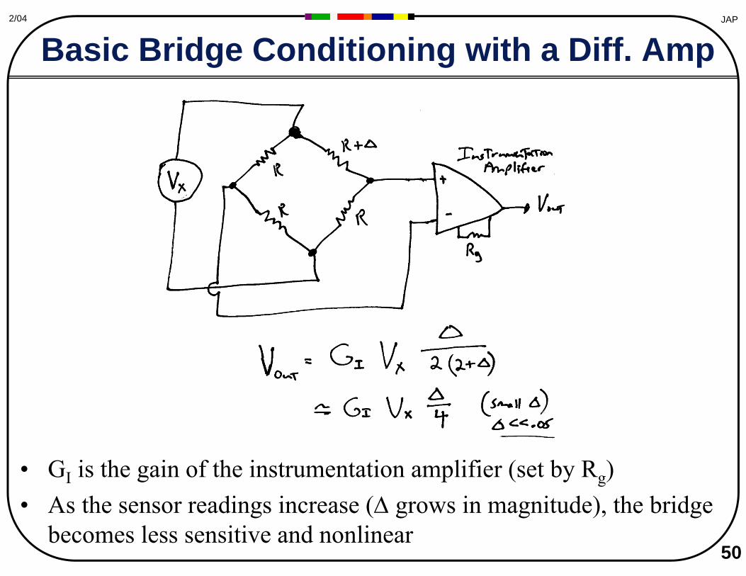
Basic Bridge Conditioning with a Diff. Amp P2/04
• GI is the gain of the instrumentation amplifier (set by Rg) • As the sensor readings increase (Δ grows in magnitude), the bridge
becomes less sensitive and nonlinear

JAP2/04
Servo’ed Resistor Balance
• A voltage (or digitally) variable resistor is adjusted in the negative feedback loop of an OpAmp to maintain the bridge’s null – Feedback works to make R1 + Δ + δR = R 51
52
JAP2/04
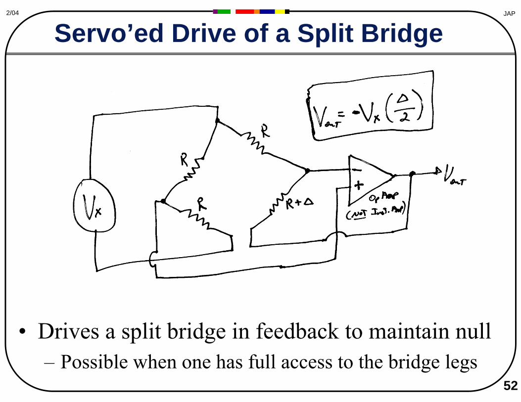
Servo’ed Drive of a Split Bridge
• Drives a split bridge in feedback to maintain null – Possible when one has full access to the bridge legs
53
JAP2/04
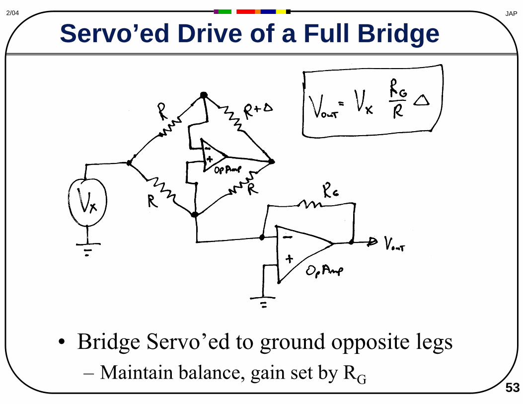
Servo’ed Drive of a Full Bridge
• Bridge Servo’ed to ground opposite legs – Maintain balance, gain set by RG

54 Courtesy of Texas Instruments. Used with permission.
JAP2/04
Packaged Bridge Amplifiers BurrBrown (TI) XTR106
MIT OpenCourseWarehttp://ocw.mit.edu
MAS.836 Sensor Technologies for Interactive Environments Spring 2011
For information about citing these materials or our Terms of Use, visit: http://ocw.mit.edu/terms.