Embed Size (px)
Citation preview

MAS-1
i
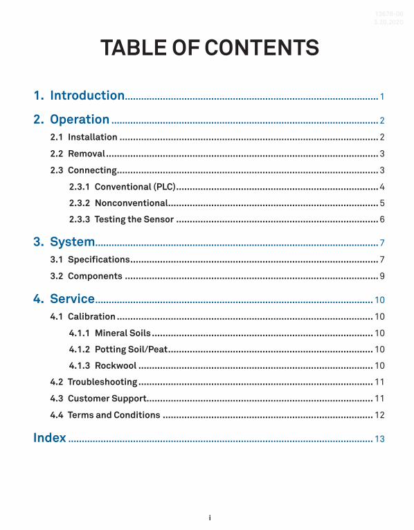
TABLE OF CONTENTS
1. Introduction .............................................................................................. 1
2. Operation ................................................................................................... 2
2.1 Installation ................................................................................................ 2
2.2 Removal ..................................................................................................... 3
2.3 Connecting ................................................................................................. 3
2.3.1 Conventional (PLC) ........................................................................... 4
2.3.2 Nonconventional .............................................................................. 5
2.3.3 Testing the Sensor ........................................................................... 6
3. System ......................................................................................................... 7
3.1 Specifications ............................................................................................ 7
3.2 Components .............................................................................................. 9
4. Service ....................................................................................................... 10
4.1 Calibration ............................................................................................... 10
4.1.1 Mineral Soils .................................................................................. 10
4.1.2 Potting Soil/Peat ............................................................................ 10
4.1.3 Rockwool ....................................................................................... 10
4.2 Troubleshooting ....................................................................................... 11
4.3 Customer Support.................................................................................... 11
4.4 Terms and Conditions .............................................................................. 12
Index ................................................................................................................. 13
13678-063.20.2020

1
1. INTRODUCTIONThank you for choosing the MAS-1 Soil Moisure Sensor from METER Group. This innovative sensor monitors soil moisture accurately with a standard 2-wire, 4- to 20-mA analog interface for use with many data acquisition and control systems. The MAS-1 cannot be used with the standard METER data loggers.
Prior to use, verify the sensor arrived in good condition.
2
OPERATION
2. OPERATIONPlease read all instructions before operating the MAS-1 to ensure it performs to its full potential.
PRECAUTIONSMETER sensors are built to the highest standards, but misuse, improper protection, or improper installation may damage the sensor and possibly void the manufacturer’s warranty. Before integrating MAS-1 into a system, make sure to follow the recommended installation instructions and have the proper protections in place to safeguard sensors from damage.
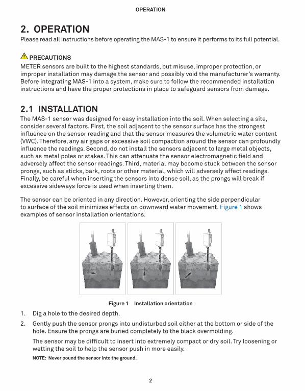
2.1 INSTALLATIONThe MAS-1 sensor was designed for easy installation into the soil. When selecting a site, consider several factors. First, the soil adjacent to the sensor surface has the strongest influence on the sensor reading and that the sensor measures the volumetric water content (VWC). Therefore, any air gaps or excessive soil compaction around the sensor can profoundly influence the readings. Second, do not install the sensors adjacent to large metal objects, such as metal poles or stakes. This can attenuate the sensor electromagnetic field and adversely affect the sensor readings. Third, material may become stuck between the sensor prongs, such as sticks, bark, roots or other material, which will adversely affect readings. Finally, be careful when inserting the sensors into dense soil, as the prongs will break if excessive sideways force is used when inserting them.
The sensor can be oriented in any direction. However, orienting the side perpendicular to surface of the soil minimizes effects on downward water movement. Figure 1 shows examples of sensor installation orientations.
Figure 1 Installation orientation
1. Dig a hole to the desired depth.
2. Gently push the sensor prongs into undisturbed soil either at the bottom or side of the hole. Ensure the prongs are buried completely to the black overmolding.
The sensor may be difficult to insert into extremely compact or dry soil. Try loosening or wetting the soil to help the sensor push in more easily.NOTE: Never pound the sensor into the ground.
3
MAS-1
3. Carefully backfill the hole to match the bulk density of the surrounding soil. Be careful to not over stress the cable or overmold by bending when installing the sensor.
2.2 REMOVALWhen removing the sensor from the soil, do not pull it out of the soil by the cable! Doing so may break internal connections and make the sensor unusable.
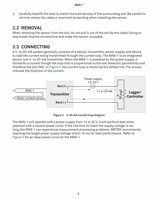
2.3 CONNECTINGA 4- to 20-mA system generally consists of a sensor, transmitter, power supply, and device to read the current being transmitted through the current loop. The MAS-1 is an integrated sensor and 4- to 20-mA transmitter. When the MAS-1 is powered by the power supply, it transmits a current though the loop that is proportional to the soil dielectric permittivity and therefore the soil VWC. In Figure 2, the current loop is shown by the dotted line. The arrows indicate the direction of the current.
I = 4–20 mAMAS-1
Water content sensor
Power supply12–32 V
RLo
ad
Red (+)
Black (–)
Transmitter Logger/Controller
Figure 2 4-20 mA current loop diagram
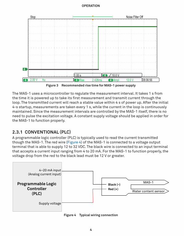
The MAS-1 will operate with a power supply from 12 to 32 V. It will perform best when powered with a square power curve. If the rise time to reach the supply voltage is too long, the MAS-1 can experience measurement processing problems. METER recommends reaching the target power supply voltage within 10 ms for best performance. Refer to Figure 3 for an ideal power curve for the MAS-1.
4
OPERATION
4444
4
Rise 2.426ms2.00 V
Noise Filter OffStop
BW Ampl 12.0 V 08:06:5610.0 V1.00 s
[ ]
Figure 3 Recommended rise time for MAS-1 power supply
The MAS-1 uses a microcontroller to regulate the measurement interval. It takes 1 s from the time it is powered up to take its first measurement and transmit current through the loop. The transmitted current will reach a stable value within 4 s of power up. After the initial 4-s startup, measurements are taken every 1 s, while the current in the loop is continuously maintained. Since the measurement intervals are controlled by the MAS-1 itself, there is no need to pulse the excitation voltage. A constant supply voltage should be applied in order for the MAS-1 to function properly.
2.3.1 CONVENTIONAL (PLC)A programmable logic controller (PLC) is typically used to read the current transmitted though the MAS-1. The red wire (Figure 4) of the MAS-1 is connected to a voltage output terminal that is able to supply 12 to 32 VDC. The black wire is connected to an input terminal that accepts a current input ranging from 4 to 20 mA. For the MAS-1 to function properly, the voltage drop from the red to the black lead must be 12 V or greater.
Water content sensor
MAS-1Programmable LogicController
(PLC)
4–20 mA input(Analog current input)
Supply voltage
Red (+)
Black (–)
Figure 4 Typical wiring connection
5
MAS-1
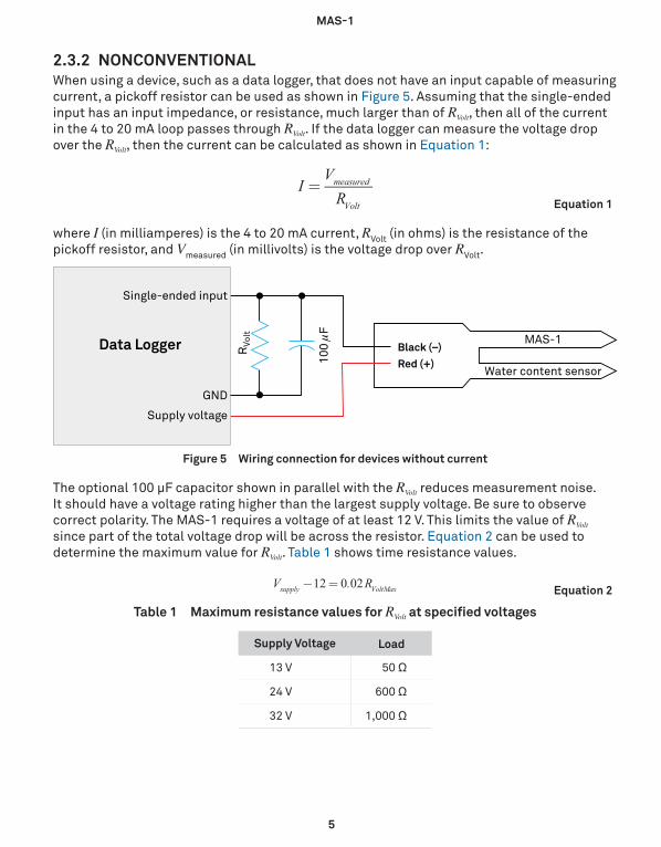
2.3.2 NONCONVENTIONALWhen using a device, such as a data logger, that does not have an input capable of measuring current, a pickoff resistor can be used as shown in Figure 5. Assuming that the single-ended input has an input impedance, or resistance, much larger than of RVolt, then all of the current in the 4 to 20 mA loop passes through RVolt. If the data logger can measure the voltage drop over the RVolt, then the current can be calculated as shown in Equation 1:
Equation 1I
VRmeasured
Volt
=
where I (in milliamperes) is the 4 to 20 mA current, RVolt (in ohms) is the resistance of the pickoff resistor, and Vmeasured (in millivolts) is the voltage drop over RVolt.
Water content sensor
MAS-1Data Logger
Single-ended input
Supply voltage
GND
RVo
lt
100 µ
F
Red (+)
Black (–)
Figure 5 Wiring connection for devices without current
The optional 100 μF capacitor shown in parallel with the RVolt reduces measurement noise. It should have a voltage rating higher than the largest supply voltage. Be sure to observe correct polarity. The MAS-1 requires a voltage of at least 12 V. This limits the value of RVolt since part of the total voltage drop will be across the resistor. Equation 2 can be used to determine the maximum value for RVolt. Table 1 shows time resistance values.
Equation 2V . R12 0 02supply VoltMax− =
Table 1 Maximum resistance values for RVolt at specified voltages
Supply Voltage Load
13 V 50 Ω
24 V 600 Ω
32 V 1,000 Ω
6
OPERATION
1. The supply voltage does not need to be regulated for the sensor to work properly; it can be any value between 12 and 32 V, without affecting sensor output.
2. The signal is not affected by electrical resistance in the cable, so the sensor output is not affected by cable length or wire gauge.
3. The MAS-1 requires only two conductors, so long lines are both lower in noise and less expensive.
4. The source impedance is small, and a current loop is highly immune to noise on the line.
5. Measured voltage can be tailored to a particular data acquisition system simply by adjusting the value of RVolt. A typical application might be to use a MAS-1 with a 12-V supply and an RVolt value of 1 Ω. The output voltage range is the product of the current and the resistance (Equation 1), so it would be 4 to 20 mA for 4 to 29 mV.
2.3.3 TESTING THE SENSORAfter integrating the MAS-1 into the data acquisition system, test the sensor output to verify it is functioning correctly with the system. Two convenient test conditions are surrounding the sensor with either air or water.• To test in air, suspend the sensor from the cable, at least 15.25 cm (6 in) from any object.
The sensor should transmit between approximately 3.4 to 4.7 mA.
• To test in water, place the sensor in a bucket of tap water (do not use deionized or distilled water). The entire sensor (prongs and black sensor body) should be immersed in water, and should be at least 5 cm (2 in) from any container surface. The sensor should transmit between approximately 18.1 to 22.4 mA.
NOTE: Sensor output can go above 20 mA and below 4 mA.
7
MAS-1
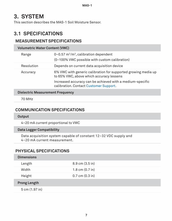
3. SYSTEMThis section describes the MAS-1 Soil Moisture Sensor.
3.1 SPECIFICATIONSMEASUREMENT SPECIFICATIONS
Volumetric Water Content (VWC)
Range 0−0.57 m3/m3, calibration dependent
(0–100% VWC possible with custom calibration)
Resolution Depends on current data acquisition device
Accuracy 6% VWC with generic calibration for supported growing media up to 65% VWC, above which accuracy lessens
Increased accuracy can be achieved with a medium-specific calibration. Contact Customer Support.
Dielectric Measurement Frequency
70 MHz
COMMUNICATION SPECIFICATIONSOutput
4–20 mA current proportional to VWC
Data Logger Compatibility
Data acquisition system capable of constant 12–32 VDC supply and 4–20 mA current measurement.
PHYSICAL SPECIFICATIONSDimensions
Length 8.9 cm (3.5 in)
Width 1.8 cm (0.7 in)
Height 0.7 cm (0.3 in)
Prong Length
5 cm (1.97 in)
8
SYSTEM
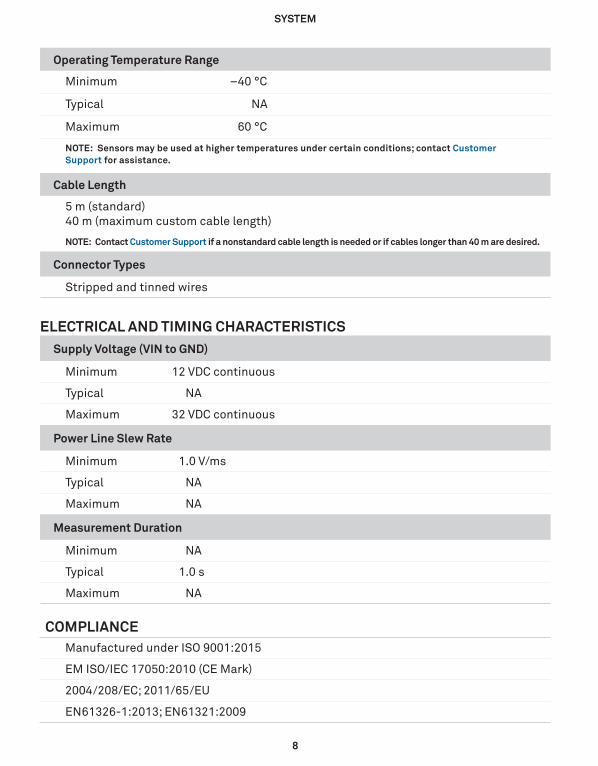
Operating Temperature Range
Minimum –40 °C
Typical NA
Maximum 60 °C
NOTE: Sensors may be used at higher temperatures under certain conditions; contact Customer Support for assistance.
Cable Length
5 m (standard) 40 m (maximum custom cable length)
NOTE: Contact Customer Support if a nonstandard cable length is needed or if cables longer than 40 m are desired.
Connector Types
Stripped and tinned wires
ELECTRICAL AND TIMING CHARACTERISTICSSupply Voltage (VIN to GND)
Minimum 12 VDC continuous
Typical NA
Maximum 32 VDC continuous
Power Line Slew Rate
Minimum 1.0 V/ms
Typical NA
Maximum NA
Measurement Duration
Minimum NA
Typical 1.0 s
Maximum NA
COMPLIANCEManufactured under ISO 9001:2015
EM ISO/IEC 17050:2010 (CE Mark)
2004/208/EC; 2011/65/EU
EN61326-1:2013; EN61321:2009
9
MAS-1
3.2 COMPONENTSThe MAS-1 measures the capacitance of the soil to find its volumetric water content (VWC). Since the capacitance of water is much higher than that of air or soil minerals, the capacitance of the soil is a sensitive measure of water content. The MAS-1 supplies a 70-MHz oscillating wave to the sensor prongs that induces an electromagnetic field in the medium (soil) surrounding the sensor. The charging and discharging of the sensor is controlled by the dielectric of the surrounding soil.
The microprocessor makes a dielectric measurement and updates the transmitted current once per second. The transmitted 4- to 20-mA current can be converted to the water content of the soil using a simple calibration function. The MAS-1 is designed to be used with standard 4-to 20-mA controllers and monitoring systems. It cannot be used with METER data loggers. For more information about using METER data loggers, please contact Customer Support.
10
SERVICE
4. SERVICEThis section contains calibration information, customer support contact information, and terms and conditions.
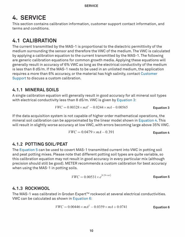
4.1 CALIBRATIONThe current transmitted by the MAS-1 is proportional to the dielectric permittivity of the medium surrounding the sensor and therefore the VWC of the medium. The VWC is calculated by applying a calibration equation to the current transmitted by the MAS-1. The following are generic calibration equations for common growth media. Applying these equations will generally result in accuracy of 6% VWC as long as the electrical conductivity of the medium is less than 8 dS/m. If the MAS-1 needs to be used in an unlisted medium, the application requires a more than 6% accuracy, or the material has high salinity, contact Customer Support to discuss a custom calibration.
4.1.1 MINERAL SOILSA single calibration equation will generally result in good accuracy for all mineral soil types with electrical conductivity less than 8 dS/m. VWC is given by Equation 3:
Equation 3VWC . mA . mA .0 00328 0 0244 0 005652= × − × −
If the data acquisition system is not capable of higher order mathematical operations, the mineral soil calibration can be approximated by the linear model shown in Equation 4. This will result in slightly worse accuracy at low VWC, with errors becoming large above 35% VWC.
Equation 4VWC . mA .0 0479 0 391= × −
4.1.2 POTTING SOIL/PEATThe Equation 5 can be used to covert MAS-1 transmitted current into VWC in potting soil and peat potting mixes. Please note that different potting soil types are quite variable, so this calibration equation may not result in good accuracy in every particular mix (although precision should still be good). METER recommends a custom calibration for best accuracy when using the MAS-1 in potting soils.
Equation 5VWC . e0 00531 . mA0 29= × ( )×
4.1.3 ROCKWOOLThe MAS-1 was calibrated in Grodan ExpertTM rockwool at several electrical conductivities. VWC can be calculated as shown in Equation 6:
Equation 6VWC . mA . mA .0 00446 0 0359 0 07412= × − × +

11
MAS-1
4.2 TROUBLESHOOTINGTable 2 lists common problems and their solutions. If the problem is not listed or these solutions do not solve the issue, contact Customer Support.
Table 2 Troubleshooting the MAS-1
Problem Possible Solutions
Readings are outside expected ranges
Check the connection to the PLC or other data acquisition system.
Check the wiring and make sure that the supply voltage is in the specified range.
Readings are negative while in soil
Ensure good sensor-to-soil contact. When inserted, the MAS-1 should be completely covered up past the black sensor body. Removing and reinstalling should remedy this problem.
4.3 CUSTOMER SUPPORTNORTH AMERICACustomer service representatives are available for questions, problems, or feedback Monday through Friday, 7:00 am to 5:00 pm Pacific time.
Email: [email protected] [email protected]
Phone: +1.509.332.5600
Fax: +1.509.332.5158
Website: metergroup.com
EUROPECustomer service representatives are available for questions, problems, or feedback Monday through Friday, 8:00 to 17:00 Central European time.
Email: [email protected] [email protected]
Phone: +49 89 12 66 52 0
Fax: +49 89 12 66 52 20
Website: metergroup.de
12
SERVICE
If contacting METER by email, please include the following information:
Name Address Phone
Email address Instrument serial numberDescription of the problem
NOTE: For products purchased through a distributor, please contact the distributor directly for assistance.
4.4 TERMS AND CONDITIONSBy using METER instruments and documentation, you agree to abide by the METER Group, Inc. USA Terms and Conditions. Please refer to metergroup.com/terms-conditions for details.
INDEX
13
INDEXA
accuracy 7
C
cable length 8calibration 10compliance 8connector types 8customer support 11
E
email address 11
F
fax number 11
I
installation 2
P
phone number 11
R
range 7rise time 3
S
specifications 7–8communication 7data logger compatibility 8measurement specifications 7physical 7
T
terms and conditions 12

14566-06 3.20.2020
METER Group, Inc. USA2365 NE Hopkins Court Pullman, WA 99163
T: +1.509.332.2756 F: +1.509.332.5158E: [email protected] W: metergroup.com
METER Group AGMettlacher Straße 8, 81379 München
T: +49 89 1266520 F: +49 89 12665220E: [email protected] W: metergroup.de
© 2011–2012, 2019–2020 All Rights Reserved.