Embed Size (px)
Citation preview
DRAFT
1
Using Marx Automatic Control Signals for Multi-block Control John Gilmer, Jr.
Draft of August 1, 2011
Background: In the pre-WW2 era,, Marx made the Trainmaster #1405 automatic block signal. This sophisticated and complex device controlled a “block section” of track, to stop a locomotive on that section, allow it to proceed slowly, or at full speed, depending on the color of the signal, red, yellow or green respectively. The heart of the device was a three state double pole solenoid which was “tripped” by the previous train passing first a red, then yellow, then green control contacts farther down the track. While the simplest configuration was one signal controlling two trains on one loop, there was no theoretical reason why this controller could not be used in cascaded fashion with an arbitrary number around a loop. With only one train present, it would always get a green by the time it came back around to a given signal. The reasons for this was not done, and the trainmaster remains an obscure device, is that it did not work well. The solenoid mechanism was very complex and prone to failure (Twarog 2007). Postwar, Marx made a simpler signal that was conceptually similar in what one expected to see: two trains operating on a single track, with a control signal stopping a train until the earlier one was clear. This “twin train sets” controller (unnumbered as far as I know) was much simpler and relatively reliable. However, it was very limited, compared to a correctly operating trainmaster, in what it could do. As designed and marketed, it was pretty much limited to two trains on a loop control. Yet, it would seem that more might have been possible with this piece. It’s simplicity and reliability compared to the Trainmaster would have opened the possibilities for multi-block control. Why was that not pursued? This paper is an attempt to explore that issue, and see what might be possible with these signals.
Although they are not common, these control signals do seem to be available enough for a typical collector to run a nice loop with several trains running at the same time, if the technical issues in using this signal can be solved. The Automatic Control Signal for Twin train Sets The assumption is that the signal operates on a loop, in which the track is segmented into three sections. Trains operate in only one direction, and the set included two “forward only” locomotives. The track sections are, in the order the train encounters them, the “Main Section” which is uncontrolled and unsensed, a “Control Section” in which the presence of a train is sensed, and a “Block Section” in which a train is controlled. In the block section power is provided to the center rail, or it is not, depending on the state of the system. The heart of the signal is a solenoid (or “relay”) which is operated by a train passing into a “control section” of the loop. The solenoid is normally open, turning off power to the block section, prohibiting the train in the block from moving. When the other train moves from the main section to the control section, it draws center rail power through the solenoid coil, activating the device to switch power on the block section. The train there then proceeds onto the main section before the second train moves from the control section to the block section.

DRAFT
2
The signal itself shows some unusual features. Instead of knurled terminals, wires are directly soldered to simple eyelet terminals, and at the other ends of the wires are soldered the track terminals needed to operate the train set in just the manner described. This would have made the signal less expensive, but also less adaptable. It seemed that for Marx, adaptability for more general use wasn’t even a consideration; this signal was intended to be used only in the context of that one set operated with no significant modifications to the configuration. John Twarog has described this signal and its operation in much greater detail (Twarog 2006). A diagram of the train configuration with a schematic of the signal is shown from his paper in Figure 1 below.
Figure 1: The Automatic Control Signal as used singly for two train control
DRAFT
3
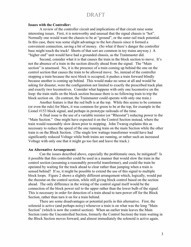
Issues with the Controller: A review of the controller circuit and implications of that circuit raise some
interesting issues. First, it is noteworthy and unusual that the signal chassis is “hot”. Normally one would want the chassis to be at “ground”, or the outer rail track potential. In this case, there was some slight advantage to the hot chassis since it formed a convenient connection, saving a bit of money. (So what if there’s danger the controller base might touch the track! Shorts of that sort are common in toy trains anyway.) A “higher end” unit would have had a grounded chassis, as the Trainmaster did.
Second, consider what it is that causes the train in the block section to move. It’s not the absence of a train in the section directly ahead from the signal. The “Main section” is unsensed. No, it is the presence of a train coming up behind the one on the control section that causes the train to be allowed move. So, instead of the controller stopping a train because the next block is occupied, it pushes a train forward blindly because another is coming up behind. This would make no sense at all and would be asking for disaster, were the configuration not limited to exactly the prescribed track plan and exactly two locomotives. Consider what happens with only one locomotive on the loop: the train stalls on the block section because there is no following train to trip the block section on. (In contrast, the Trainmaster could operate with only one train.)
Another feature is that the red bulb is at the top. While this seems to be common (or even the rule) for Marx, it was common for green to be at the top, for example in the Lionel #153 block signal, and perhaps in prototype railroads of the time.
A final issue is the use of a variable resistor (or “Rheostat”) reducing power to the “Main Section.” One might have expected it on the Control Section instead, where the train would reasonably slow down prior to stopping. John Twarog explains this as necessary to reduce the speed of the one running train on the main Section while the other train is on the Block Section. (The single low wattage transformer would have had significantly reduced Voltage while both trains are running, or rather such an increased Voltage with only one that it might go too fast and leave the track.)
An Alternative Arrangement:
Can the issues described above, especially the problematic ones, be mitigated? Is it possible that this controller could be used in a manner that would slow the train in the control section (assuming a reasonably powerful transformer), and could the train be operated by waiting for the track ahead to clear rather than jumping when a train is sensed behind? If so, it might be possible to extend the use of this signal to multiple block loops. Figure 2 shows a slightly different arrangement which, logically, would put the rheostat on the control section, while still giving block control based on the section ahead. The only difference in the wiring of the control signal itself would be the connection of the block power rail to the upper rather than the lower bulb of the signal. This is necessary in order for detection of a train ahead to turn power off for the Block Section, rather than turn it on for a train behind. There are some disadvantages or potential perils in this alternative. First, the solenoid is active (and perhaps noisy) whenever a train is on what was the long “Main Section” (which is now the control section). When an earlier train leaves the Main Section (onto the Uncontrolled Section, formerly the Control Section) the train waiting in the Block Section moves forward, and almost immediately the solenoid is active again.

DRAFT
4
The solenoid seems robust enough to be able to handle the power almost continuously (typically about a Watt), but it’s still somewhat preferable to have less noise.
Figure 2 An Alternative single controller arrangement
A more serious operational disadvantage is that if the train on the Main Section does not maintain continuous contact, the solenoid will trip on, perhaps allowing the blocked train to move onto the Control Section. (The complementary issue in the original configuration is that poor contact by the following train on the control section stalls both trains. Not sure the problem here is any worse.) If the Main Section includes a crossover (especially a newer one with no contact in the middle) the problem of loss of contact is potentially worse. However, the flat sliding shoe center rail contact Marx uses does better at maintaining reliable electrical contact than rollers (use by Lionel and others). It remains to be seen whether this is really a problem or not.
After looking at this, in theory it would seem to be superior to the actual Marx circuit. It works with one locomotive. It would seem to be possible to cascade similar signals. In this circuit the rheostat is where you’d want it: to slow the locomotive down approaching the block section. The question is, why was it that Marx didn’t do it this way. Might that perhaps have been their original intention? Or was this controller from the beginning a clever

DRAFT
5
marketing ploy to entice buyers with a clever and attractive concept that was cheaply implemented and not extensible? Might Marx have thought about using a thermal relay activated by the rheostat rather than an electromechanical one? That would be a good reason for a rheostat on the main line. The hot rheostat would cause the relay to go to the normally open position, turning on the red bulb and turning off power to the block section. This would have had the same advantages of the alternative arrangement described above, but should have been even less expensive, assuming a bimetallic thermal relay would be cheaper than the electromechanical one. Multiple Block Control Approach (Single direction): There are two basic problems to using this signal for multiple block control in a manner similar to the “alternative” single control circuit above. First, the signal must be modified to provide another wire for “normally closed”, as is true for the alternative above. This requires opening up the signal and soldering a wire to the solenoid contact at the same point that the red wire is attached. This is shown in Figure 3.
Figure 2 Additional wire for “Normally Closed” contact
The second issue is that the sense coil (the solenoid armature) is physically connected to the chassis of the controller, as is the contactor of the points. If these were separate, you could put the armature in series with the feed for the control section, without needing one end to be hot (or grounded). Without disconnecting the solenoid chassis connection (and adding yet another wire), it is possible to handle this problem by alternating control of the center rail and of the outside rails. Figure 4 illustrates. In this

DRAFT
6
manner, any even number of controllers can be spaced out around a loop. Note that the “Uncontrolled” section is gone. Every section is either a control section or a block section. The question remains whether this works in practice.
Figure 4 Multiple Block Control Approach (simplified)
Testing and Characterization: In order for the multi-block control system to work, and work well, several conditions need to be satisfied. First and most important, a train on a “control” section must trip the solenoid in the previous block section to the “normally open” position n, removing power in the block section. Tests were made with two available signals to see how much current was required, as shown in Table 1. Current was provided from a conventional AC train transformer (American Flyer AF 168B, rated 190W) at about 16VAC.
The amount of current was determined by a number of light bulbs (or locomotive) paralleled in the solenoid armature current path. 24V rated bulbs drew about .134A, and 12-15V rated bulbs, the globe type used for street lamps, drew .265A. A Marx #400 locomotive (E unit, lamp) drew about 2.2A to 2.4A. A #333 (which also has smoke) drew about 2.6A – 2.7A, and a #666 drew about 2.3A at the test Voltage setting.
DRAFT
7
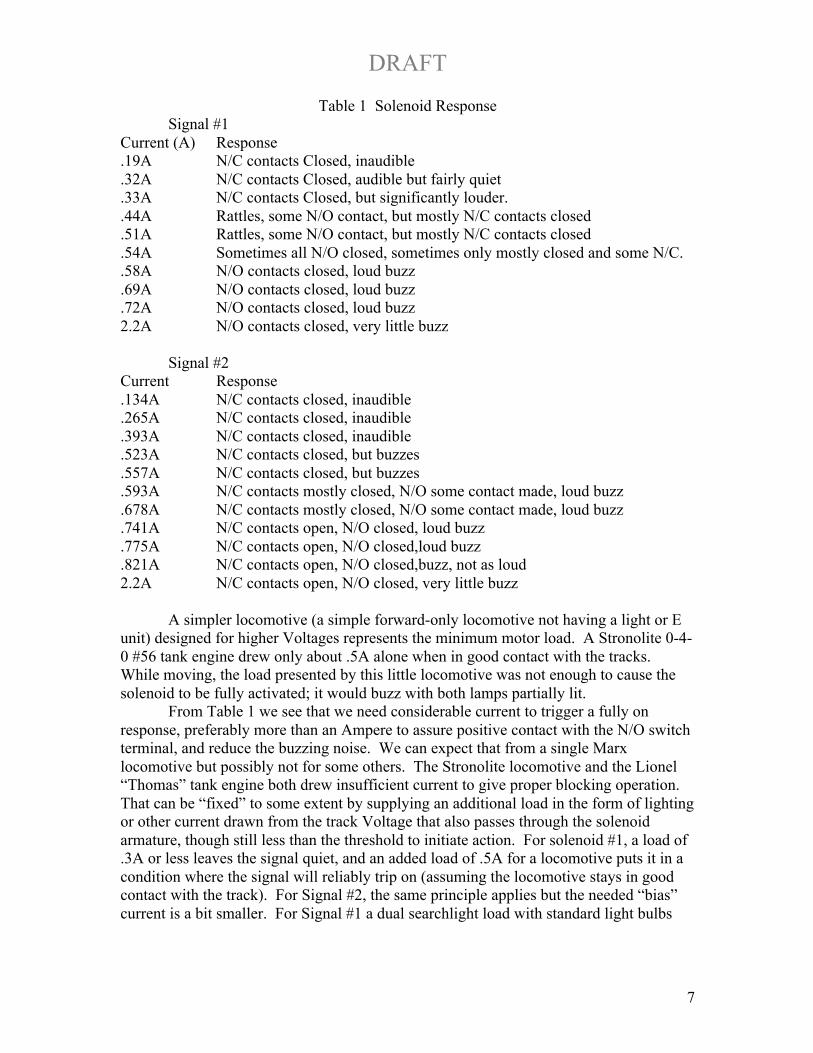
Table 1 Solenoid Response Signal #1 Current (A) Response .19A N/C contacts Closed, inaudible .32A N/C contacts Closed, audible but fairly quiet .33A N/C contacts Closed, but significantly louder. .44A Rattles, some N/O contact, but mostly N/C contacts closed .51A Rattles, some N/O contact, but mostly N/C contacts closed .54A Sometimes all N/O closed, sometimes only mostly closed and some N/C. .58A N/O contacts closed, loud buzz .69A N/O contacts closed, loud buzz .72A N/O contacts closed, loud buzz 2.2A N/O contacts closed, very little buzz Signal #2 Current Response .134A N/C contacts closed, inaudible .265A N/C contacts closed, inaudible .393A N/C contacts closed, inaudible .523A N/C contacts closed, but buzzes .557A N/C contacts closed, but buzzes .593A N/C contacts mostly closed, N/O some contact made, loud buzz .678A N/C contacts mostly closed, N/O some contact made, loud buzz .741A N/C contacts open, N/O closed, loud buzz .775A N/C contacts open, N/O closed,loud buzz .821A N/C contacts open, N/O closed,buzz, not as loud 2.2A N/C contacts open, N/O closed, very little buzz
A simpler locomotive (a simple forward-only locomotive not having a light or E
unit) designed for higher Voltages represents the minimum motor load. A Stronolite 0-4-0 #56 tank engine drew only about .5A alone when in good contact with the tracks. While moving, the load presented by this little locomotive was not enough to cause the solenoid to be fully activated; it would buzz with both lamps partially lit. From Table 1 we see that we need considerable current to trigger a fully on response, preferably more than an Ampere to assure positive contact with the N/O switch terminal, and reduce the buzzing noise. We can expect that from a single Marx locomotive but possibly not for some others. The Stronolite locomotive and the Lionel “Thomas” tank engine both drew insufficient current to give proper blocking operation. That can be “fixed” to some extent by supplying an additional load in the form of lighting or other current drawn from the track Voltage that also passes through the solenoid armature, though still less than the threshold to initiate action. For solenoid #1, a load of .3A or less leaves the signal quiet, and an added load of .5A for a locomotive puts it in a condition where the signal will reliably trip on (assuming the locomotive stays in good contact with the track). For Signal #2, the same principle applies but the needed “bias” current is a bit smaller. For Signal #1 a dual searchlight load with standard light bulbs

DRAFT
8
provided the bias. For Signal #2, a similar streetlight load was added, with one of the bulbs replaced by a 24V light bulb to reduce the current draw and quiet the signal.
The two signals were put onto an O-27 test track as shown in Figure 5. The block sections were two straight section for #1 and 1 ½ sections for #2 and the short control section 3 track sections long. At the ends were ½ sections connected to the curves. The upper straight sections and signals were secured to a board; the remainder was loose track.
Figure 5 Multiblock Signal test track When operated with a single Marx #400 locomotive, both signals operated as expected, cleanly switching between Green and Red phases reliably and with little noise when on.
With a single moving low current locomotive, the Stronolite #56 (one direction, no E unit or bulb), the current drawn while on Control Section 1 was insufficient for the signal to stay Red (blocking Block Section 1). Both bulbs of the signal were partially lit. Adding bias (an additional 24V light bulb) made the signal less than fully “On” with no locomotive on Control Section 1. Signal 2 seemed to work well even for a light locomotive load. Another problem became apparent that was not noticed earlier. A locomotive waiting on Block Section 2 really needs to wait not only for Control Section 2 to be clear, but also Block Section 1. If a train were waiting on Block Section 1, a train released from Block section 2 would hit it, exactly what needs to be avoided. In order to detect a train on block section 1, current needs to pass through the Signal 1 circuit, enough to be detectable by the Signal 2 armature, but not enough to cause the locomotive to move.
One way of accomplishing this is using the resistor included in the signal; it can be wired in shunt with the switch (N/C or Green position) to provide a bit of track power while the locomotive is waiting. (As an extra benefit, this current would also keep the E-unit in the locomotive from tripping if it has one, perhaps allowing normal reversible locomotives to be used.) But there are two problems with this potential solution. The more severe problem is that the green signal light remains on along with the red one, by drawing current through the resistor when the red light is on. Another potential problem, but manageable, is that the solenoid must now be sensitive enough for a reduced load of the locomotive in series with the resistor to make it trip. This is not a problem with one
DRAFT
9
of the mentioned Marx locomotives. But it is a problem with the low current smaller locomotives.
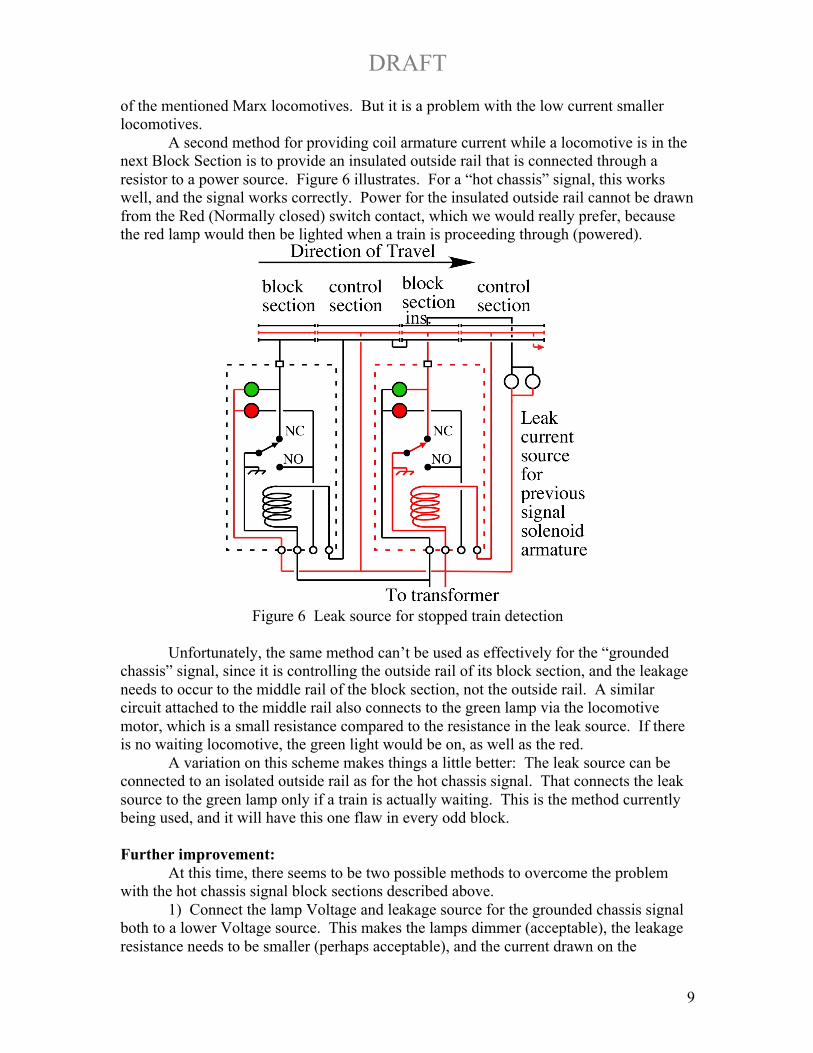
A second method for providing coil armature current while a locomotive is in the next Block Section is to provide an insulated outside rail that is connected through a resistor to a power source. Figure 6 illustrates. For a “hot chassis” signal, this works well, and the signal works correctly. Power for the insulated outside rail cannot be drawn from the Red (Normally closed) switch contact, which we would really prefer, because the red lamp would then be lighted when a train is proceeding through (powered).
Figure 6 Leak source for stopped train detection
Unfortunately, the same method can’t be used as effectively for the “grounded
chassis” signal, since it is controlling the outside rail of its block section, and the leakage needs to occur to the middle rail of the block section, not the outside rail. A similar circuit attached to the middle rail also connects to the green lamp via the locomotive motor, which is a small resistance compared to the resistance in the leak source. If there is no waiting locomotive, the green light would be on, as well as the red.
A variation on this scheme makes things a little better: The leak source can be connected to an isolated outside rail as for the hot chassis signal. That connects the leak source to the green lamp only if a train is actually waiting. This is the method currently being used, and it will have this one flaw in every odd block.
Further improvement: At this time, there seems to be two possible methods to overcome the problem with the hot chassis signal block sections described above.
1) Connect the lamp Voltage and leakage source for the grounded chassis signal both to a lower Voltage source. This makes the lamps dimmer (acceptable), the leakage resistance needs to be smaller (perhaps acceptable), and the current drawn on the
DRAFT
10
transformer when a locomotive is in the block section (on) is larger since the locomotive and leakage source will both be on at the same time. This method has the advantage of not requiring any additional modification of the signal. A second, lower Voltage transformer or transformer tap is needed.
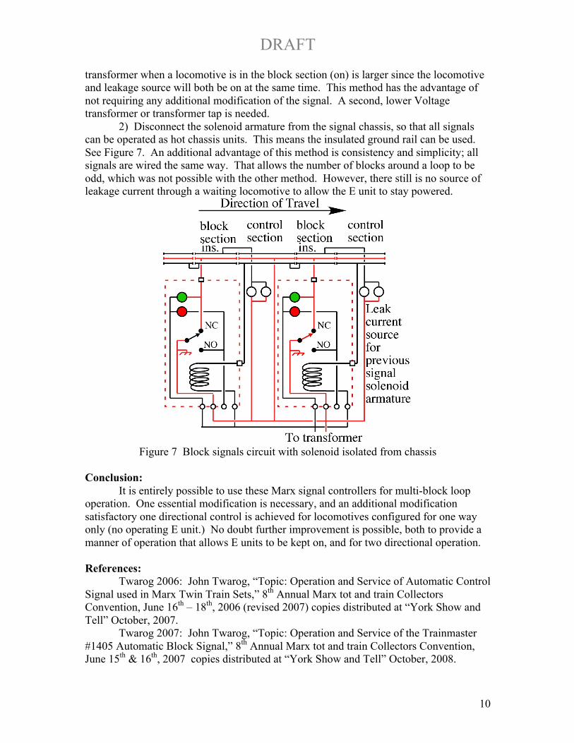
2) Disconnect the solenoid armature from the signal chassis, so that all signals can be operated as hot chassis units. This means the insulated ground rail can be used. See Figure 7. An additional advantage of this method is consistency and simplicity; all signals are wired the same way. That allows the number of blocks around a loop to be odd, which was not possible with the other method. However, there still is no source of leakage current through a waiting locomotive to allow the E unit to stay powered.
Figure 7 Block signals circuit with solenoid isolated from chassis
Conclusion: It is entirely possible to use these Marx signal controllers for multi-block loop operation. One essential modification is necessary, and an additional modification satisfactory one directional control is achieved for locomotives configured for one way only (no operating E unit.) No doubt further improvement is possible, both to provide a manner of operation that allows E units to be kept on, and for two directional operation. References:
Twarog 2006: John Twarog, “Topic: Operation and Service of Automatic Control Signal used in Marx Twin Train Sets,” 8th Annual Marx tot and train Collectors Convention, June 16th – 18th, 2006 (revised 2007) copies distributed at “York Show and Tell” October, 2007.
Twarog 2007: John Twarog, “Topic: Operation and Service of the Trainmaster #1405 Automatic Block Signal,” 8th Annual Marx tot and train Collectors Convention, June 15th & 16th, 2007 copies distributed at “York Show and Tell” October, 2008.
![Abstract arXiv:1712.09665v1 [cs.CV] 27 Dec 2017 · PDF fileAdversarial Patch Tom B. Brown, Dandelion Mané, Aurko Roy, Martín Abadi, Justin Gilmer {tombrown,dandelion,aurkor,abadi,gilmer}@](https://img.pdfslide.us/doc/110x75/5abc78f07f8b9a567c8ddba9/abstract-arxiv171209665v1-cscv-27-dec-2017-patch-tom-b-brown-dandelion-man.jpg)