Embed Size (px)
Citation preview

MARVEL: Multiple Antenna based Relative VehicleLocalizer
Dong Li†, Tarun Bansal†, Zhixue Lu† and Prasun SinhaDepartment of Computer Science and Engineering
The Ohio State UniversityColumbus, OH 43210
{lido, bansal, luz, prasun}@cse.ohio-state.edu†Co-primary authors
ABSTRACTAccess to relative location of nearby vehicles on the localroads or on the freeways is useful for providing critical alertsto the drivers, thereby enhancing their driving experienceas well as reducing the chances of accidents. The problemof determining the relative location of two vehicles can bebroken into two smaller subproblems: (i) Relative lane lo-calization, where a vehicle determines if the other vehicle isin left lane, same lane or right lane with respect to it, and(ii) Relative front-rear localization where it needs to be de-termined which of the two vehicles is ahead of the other onthe road. In this paper, we propose a novel antenna diver-sity based solution, MARVEL, that solves the two problemsof determining the relative location of two vehicles. MAR-VEL has two components: (i) a smartphone; and (ii) fourwireless radios. Unlike exisiting technologies, MARVEL canalso determine relative location of vehicles that are not inthe immediate neighborhood, thereby providing the driverwith more time to react. Further, due to minimal hard-ware requirements, the deployment cost of MARVEL is lowand it can be easily installed on newer as well as existingvehicles. Using results from our real driving tests, we showthat MARVEL is able to determine the relative lane locationof two vehicles with 96.8% accuracy. Through trace-drivensimulations, we also show that by aggregating informationacross different vehicles, MARVEL is able to increase thelocalization accuracy to 98%.
Categories and Subject DescriptorsC.2.4 [Computer-Communication Networks]: DistributedSystems—Distributed Applications; J.m [Computer Ap-plications]: Computers in Other Systems—Consumer Prod-ucts; G.2.2 [Discrete Mathematics]: Graph Theory—Graph Algorithms
Permission to make digital or hard copies of all or part of this work forpersonal or classroom use is granted without fee provided that copies arenot made or distributed for profit or commercial advantage and that copiesbear this notice and the full citation on the first page. To copy otherwise, torepublish, to post on servers or to redistribute to lists, requires prior specificpermission and/or a fee.MobiCom’12, August 22–26, 2012, Istanbul, Turkey.Copyright 2012 ACM 978-1-4503-1159-5/12/08 ...$15.00.
General TermsDesign, Experimentation, Measurement, Algorithms, Per-formance
KeywordsSmartphone, Wireless Ranging, Location Classification
1. INTRODUCTIONThe use of GPS equipped smartphones has been increasing
rapidly. But the GPS devices on the phones do not havesufficient accuracy to localize the vehicles up to the lane-level. Availability of traffic information at the micro-level orlane-level granularity is useful for multiple applications thatnot only reduces the chances of accidents but also enhancesthe driving experience. Some applications are as follows:(i) Alerting the drivers of upcoming obstacles or potholesthat are in the same lane as the vehicle, and further guidingthe driver to move to the appropriate lane to avoid them;(ii) Alerting the drivers if there is a vehicle in the blindzone or if this vehicle is tailgating another vehicle, therebyreducing the chances of collision; (iii) Alerting the driverthat the vehicle ahead is slowing down if the two vehiclesare in the same lane; (iv) Detecting the lane-level locationof slow moving vulnerable vehicles; and, (v) Determiningthe differences in speeds of different lanes, to assist in trafficplanning.
The problem of Vehicular Localization has two variants:(i) Relative Localization, where for two vehicles, the objec-tive is to determine the location of a vehicle with respect tothe other vehicle; and, (ii) Absolute Localization, where fora single vehicle, the objective is to determine its absolutelocation. In this paper we develop a novel solution calledMARVEL (Multiple Antenna based Relative Vehicle Local-izer) that provides relative localization of on-road vehicles.Specifically, for two given vehicles, V1 and V2, MARVEL usesantenna diversity to enable both of them to determine therelative position of the other vehicle among the six differentpossible regions.
Although, GPS technology is widely used for vehicularlocalization, various factors such as signal multipath, un-known delays due to ionosphere and troposphere, error inthe clocks of GPS devices, and inaccuracies in the locationsof satellites [9] reduce its accuracy. Device manufacturerssuch as Garmin report the average GPS accuracy to be 3 me-ters [9] even for devices equipped with newer WAAS (Wide

V1
V2
Direction of travel
FL
FS
FR
RL
RS
RR
Figure 1: Vehicle V1 can be in six different rela-tive positions with respect to V2: Front-Left, Front-Same, Front-Right, Rear-Left, Rear-Same and Rear-Right. Vehicle V1 is said to be in front of V2 if frontof V1 is ahead of that of V2 along the direction oftravel.
0
0.2
0.4
0.6
0.8
1
0 5 10 15 20 25
Cum
ula
tive p
robabili
ty
Difference in GPS readings (in meters)
(1.8,0.46)
CDF of GPS difference
Figure 2: Comparison of GPS trace of two smart-phones located in the same car: Cumulative distri-bution function of GPS error (in meters).
Area Augmentation System) and DGPS (Differential GPS)technology. The GPS trace collected by us for two phones(Motorola Atrix and iPhone 4) mounted next to each other(horizontal distance ≤ 1cm) on the windshield of the samecar showed similar inaccuracies. Figure 2 shows the cumu-lative probability distribution of distance between the loca-tions of the vehicle along the width of the road as reportedby the two smartphones. The width of the lanes as recom-mended by AASHTO [3] on local and arterial roads is 3.60meters. So, if the error is more than 1.80 meters across thedirection of travel, GPS will miscompute the relative lanelocation (left, right or same lane) of the other vehicle, whichhappens in 54% of the cases. Similarly, GPS may also in-correctly compute the relative front vs. rear location of theother vehicle if the two vehicles are close to each other. Inurban canyons, due to multipath effects, the accuracy ofGPS is expected to decrease even further. In this paper, wepropose an antenna diversity based novel solution for bothrelative lane localization and relative front-rear localization.Various vehicle manufacturers are beginning to roll out
new car models with vehicular technologies such as dopplerradar and cameras for relative localization. These technolo-gies work even when the hardware is deployed on only onevehicle (and not the other vehicles in the vicinity), but theyhave several limitations: (i) Both the doppler radar andcamera can accurately detect only those vehicles that arein the immediate neighborhood; (ii) Nearby obstacles such
as parked vehicles, store fronts and crash barriers reduce theaccuracy of the radars [10] as well as cameras [10]; (iii) Thesetechnologies cannot be easily retrofitted to existing vehicles,resulting in lower market penetration; and, (iv) There isgenerally a tradeoff between accuracy and number of radarsused [16]. More radars can cover more regions while pro-viding high localization accuracy, however this increases thedeployment cost.
MARVEL is minimal in design and consists of two com-ponents: (i) A smartphone that could be the same as onecarried by the driver; and, (ii) Four off-the-shelf wireless ra-dios mounted on the sides of the vehicle. The smartphoneruns our localization algorithm and displays relevant alertsto the driver. The wireless radios on different vehicles sendlane discovery beacons to each other and report the RSSI(Received Signal Strength Indicator) of the received beaconsto the smartphone. MARVEL determines the relative lanelocation of vehicles by leveraging the differences in RSSImeasurements due to spatial antenna diversity. MARVELis based on the observation that path loss of the links be-tween radios is asymmetrical when the vehicles are in differ-ent lanes, and it is symmetrical when the vehicles are in thesame lane. MARVEL satisifes the following desired require-ments:
• Useful information (such as presence of potholes, ap-plying hard brakes or presence of slow moving vulner-able traffic) from vehicles that are in the same laneas this vehicle, can provide the driver with more timeto react. Our system is able to detect relative loca-tion of even those vehicles that are not in the immedi-ate neighborhood (thus invisible to camera and radar),thereby providing the driver with more information toreduce the incidence of collisions. This information canalso be used for improving the design of autonomouscruise control mechanisms.
• It works in a wide variety of environmental conditionssuch as bad weather (rain, snow etc.), various lightconditions (dark, sun glare etc.), as well as in presenceof urban noise (e.g. parked cars and store fronts onroadside, crash barriers, sound walls etc.)
• It is low cost due to ubiquity of smartphones and thelow cost of wireless radios.
• It can be easily deployed on older as well as newervehicles.
• Our driving results performed using different vehiclesand under varying speed and traffic conditions showthat MARVEL computes the relative location with anaverage accuracy of 96%. By aggregating informationacross multiple vehicles, MARVEL is able to increasethe localization accuracy to 98%.
This paper is organized as follows: In Section 2, we discussrelated work in this area. Section 3 describes MARVEL indetail. In the next two sections, we describe the results fromour real driving experiments. In Section 6, we describe twoalgorithms that further improve the localization accuracy byaggregating information across different vehicles. In Section7, we describe the results from our ns-3 and SUMO basedsimulations. In Section 8, we discuss different methods thatcan make MARVEL more realistic and useful. Finally, inthe last section we conclude the paper.

2. RELATED WORKThe topics of vehicle detection and lane recognition have
been studied in the literature of autonomous vehicles fordecades. Radar [18, 2], laser [20], and acoustic [6] basedsensors and cameras are common devices in such studies.Radar, laser and acoustic sensors detect the distance of ob-jects by measuring the round trip time of signals. Thosesensors are commonly used for vehicle detection and blindspot detection. For instance, [2] embeds 24-Ghz radar sen-sors into the back side bumper to monitor the blind spots ofthe host vehicle, and triggers a vision warning signal if somevehicles are detected. However, those sensors are usuallylimited in range to line of sight, difficult to install especiallyon existing vehicles and exhibit a tradeoff between accuracyand cost. Cameras have broader application in vehicle detec-tion [11] and lane recognition [21, 7] due to their low costs.The existing solutions have used camera for recognizing ve-hicles, obstacles and lane marks through image recognitiontechniques. However, using camera for vehicle detection andlane recognition is highly susceptible to errors due to vari-ous factors such as: (i) Bad light conditions (e.g., night time,sun glare, headlight glare, shadows from nearby buildings);(ii) Improper weather conditions (e.g. snow, rain); and, (iii)Surrounding noise (e.g., faded lane marks, vehicles parkedon roadside, roadside crash barriers, trees, store fronts etc.).On the other hand, the computational power of smart-
phones is being utilized in various applications such as as-sisted driving and road infrastructure monitoring [15]. Forexample, [22] has recently proposed ways to determine if theuser of the smartphone is the driver or a passenger in thevehicle which could be used to adjust the behavior of thephone based on the owner’s type. The idea of using wirelesssensors to detect and track vehicles has been studied in [17,19]. These works mainly focus on detecting and tracking themovements of vehicles in a wireless sensor network deployedin a given area. In contrast, the objective of this paper is todetermine relative vehicle locations using multiple wirelessradios installed on vehicles.
3. SYSTEM DESIGNIn this section, we will first describe the objectives of our
solution. Then, we give an overview of our system design fol-lowed by a list of challenges. Finally, we describe MARVELin detail.
3.1 Problem StatementThe objective of our system is to determine the relative
position of two vehicles. Specifically, given two vehicles (seeFigure 1) V1 and V2, we seek to determine: (i) Relative lanelocalization: If V1 is in left lane, same lane or in right lanewith respect to V2’s lane; and, (ii) Relative front-rear local-ization: If V1 is in front or rear with respect to V2. We callthe combined problem of “Relative Lane Localization” and“Relative front-rear localization” as Relative Vehicle Local-ization. Vehicle V1 is said to be in front of V2 if the front ofV1 is ahead of that of V2 along the direction of travel. Thisdefinition also takes into account the case when one vehicleis in the blindzone of the other.
3.2 Overview and ChallengesMARVEL comprises of two components for every vehi-
cle. The first component is a smartphone that could also bethe personal smartphone of the vehicle’s driver. The second
component comprises of four wireless radios located at vari-ous positions on the lateral sides of the vehicle. We assumethat each vehicle has a unique vehicle id which could possi-bly be derived from its license plate number. The ID of thevehicle (Vi) is known to the smartphone inside the vehicleas well as the four wireless radios located on the vehicle.
We assume that the smartphone is equipped with an ac-celerometer and is Wifi capable. The smartphone (or theMARVEL application running on it) is used to communi-cate with other smartphones in other vehicles as well as todisplay alert messages. A vehicle may have multiple smart-phones present inside, however, we assume that in each vehi-cle, only one smartphone is running the relative localizationalgorithm. So, we assume that the unique phone ID of thesmartphone in vehicle Vi is Pi. If the smartphone has GPScapability, then the velocity of the vehicle can be obtainedfrom the GPS. This information along with the relative laneinformation can be used to develop various other applica-tions (see Section 1).
Our algorithm running on the smartphone keeps trackof relative locations of all nearby vehicles with whom thesmartphone can communicate. For each vehicle, it tracks:(i) The unique vehicle ID of the other vehicle; and (ii) Rel-ative location of the other vehicle, among the 6 possibleregions (see Figure 1). It is also possible to extend thisinformation to 2-hop neighbors by using multihop commu-nication. This would provide extra information to the driverand the smartphone at the cost of higher message overhead.However, in this paper, we assume that the smartphonemaintains information of vehicles that are only within onehop.
The second component of our system, comprises of fourwireless radios located on the lateral sides of the vehicle. InSection 5.2, we will show that placing the radios close to eachwheel of the vehicle maximizes the accuracy of localization.The four wireless radios communicate with radios locatedon other vehicles as well as with the smartphone locatedin the same vehicle. The radios may use Wifi or Zigbee tocommunicate with each other, while to communicate withthe phone, they can use Wifi, Bluetooth or Zigbee dependingon the capability of the radios and the smartphone. We alsoassume that the wireless radios are aware of the positionwhere they are mounted on the vehicle.
In our vehicle localization algorithm, one of the two phonesdirects its four wireless radios to send beacons, while the ra-dios on the other vehicle listen for the beacons, thereby esti-mating the path loss between the 16 pairs of wireless radios.Figure 3 shows a simpler case where only two wireless radiosare mounted on the vehicle, one on each side. Our vehiclelocalization algorithm is based on the observation that whenthe two vehicles are in same lane, the two links AD and BCare symmetrical (see Figure 3). However, when the vehiclesare in different lanes, the links AD and BC are assymmet-rical (discussed in Section 3.3.3 in more detail). However,desigining a vehicle localization system based on RSSI read-ings of the links involves multiple challenges: (i) The bestlocation to deploy the wireless radios that maximize the lo-calization accuracy needs to be determined; (ii) If a vehiclechanges its lane, the relative lane location of other vehiclesshould be updated with minimum latency while limiting thenumber of packets transmitted by radios so as to minimizecongestion and energy consumption; (iii) Packets transmit-ted may be lost due to collision with other transmissions;

B
(a) Both vehicles in same lane(c) Front vehicle in right lane(b) Front vehicle in left lane
V1
V2
A
C D
V1
V1
V2
V2
A AB B
C CD D
Figure 3: RSSI based Relative Lane Localization with two radios: A,B,C, and D are radios mounted onvehicles V1 and V2. The expected RSSI for two links AD and BC are shown for three different cases withthicker lines respresenting links with higher RSSI values. (a) When V1 and V2 are in the same lane, thenthe path losses for links AD and BC are almost symmetrical. (b) When V1 is to the left of V2, then BC is adirect line of sight link while AD passes through bodies of 2 vehicles (total of 4 walls and 1 vehicle’s heavymachinery compartment). (c) When V1 is right of V2, link AD is stronger but BC is weaker. Nearby vehiclesmay affect the signal strengths slightly due to multipath.
Monitor Phase:
Monitor
accelerometer &
Look for new phones
Beacon Phase:
Direct wireless radios
to beacon
Analyze Phase:
Determine
Relative location
Figure 4: Transitions made by the smartphoneamong the three phases.
and, (iv) Multipath propagation may affect the accuracy ofrelative localization especially if the sender and the receiverare separated by a large distance.
3.3 Lane Localization AlgorithmIn our vehicle localization algorithm, the smartphone tran-
sitions between three different phases (see Figure 4). We willnow describe the three phases of the smartphone and the lo-calization algorithm in more detail.
3.3.1 Monitor PhaseOne naive way to trigger the lane localization algorithm
is to invoke it at periodic intervals. However, this wouldinvolve considerable packet transmissions from the wirelessradios themselves, thereby affecting their battery lifetime.Further, it reduces the probability that a beacon transmit-ted is received correctly by a receiving radio. Since, lanechanges or turns are not very frequent events, therefore, inthe first phase, the smartphone itself monitors conditions
that indicate the following: (i) A possible change in rela-tive location of the vehicle with respect to other vehicles;and, (ii) Arrival of a new vehicle in the vicinity. Under bothconditions, the smartphone will inform its neighbors of apossible lane change event and move to the beacon phase.A change in relative location of a vehicle with respect toanother vehicle may happen due to two factors: (i) If thevehicle itself changes lanes or turns to a new street; or, (ii)It overtakes another vehicle. We will now discuss how thesmartphone detects all such possible events.
Detecting Possible Lane Change: To take into ac-count the first condition, the smartphone (i.e., our applica-tion running on the smartphone) continuously monitors thereadings from the accelerometer of the phone to detect pos-sible lane changes or turns. If the smartphone observes thatthe accelerometer reading is beyond a certain threshold, thephone moves to the second phase. However, as we will showin Section 4, the accelerometer readings are not completelyreliable due to factors such as potholes, bumps and slopesin the road surfaces and curvature of roads. Therefore, asdiscussed later in Section 4, MARVEL computes the differ-ence between maximum and minimum accelerometer read-ings over a window of duration 4 seconds and uses that todetect a lane change event.
Detecting Possible Overtaking: Due to differences inspeeds of different vehicles, it is possible that a vehicle V1
that was initially in one of the three rear regions of V2, laterovertakes V2, thereby changing its relative position to one ofthe three front regions of V2. In such a case, the relative lo-

calization algorithm needs to be triggered by either V1 or V2
to update the relative locations. One way to do this wouldbe to trigger the relative localization algorithm at periodicintervals. However, this would substantially reduce the life-time of the radios. Another method that could be exploredis where the phones themselves send beacons to each otherat regular intervals and also monitor the RSSI of the corre-sponding received beacons. A change in the RSSI reading ofthe beacon indicates changes in the distance between the twovehicles. A pattern in the received RSSI where it changesfrom low to high and then back to low indicates that theother vehicle is getting closer and then again getting far-ther away. If the phone observes such a pattern, it moves toPhase 2 and triggers the localization algorithm.Discovering New Vehicles in Vicinity: To estab-
lish connections with new smartphones that enter its vicin-ity and to determine the relative location of those vehicles,the smartphone broadcasts periodic discovery beacons usingUDP. The phone also listens for discovery beacons broad-cast by other phones. If the phone hears a discovery beaconfrom a previously unknown phone, the algorithm moves toPhase 2. Reducing this discovery time enables phones todetermine the relative lane location of neighboring vehiclesfaster. In order to reduce this discovery time while managingthe smartphone’s battery consumption, MARVEL can workin conjunction with any of the neighbor discovery algorithms[8, 12] that are already available in the literature.
3.3.2 Beacon PhaseIn the beacon phase, the wireless radios on the vehicle
transmit or receive beacons. Let V1 be the vehicle (withphone P1) computing its relative position and V2 (with phoneP2) be any vehicle among its set of neighbors. Then P1
will instruct its four wireless radios to send localization bea-cons while P2 instructs its radios to listen to these beacons.Each wireless radio hears multiple localization beacons, andreports the RSSI of the received beacons to its associatedphone, P2.The lane localization beacon broadcast by radios on V1
contains three fields: (i) V1; (ii) Location of the radio (amongthe four possible locations) on V1; and (iii) Transmissionpower level of the beacon. The packets transmitted by ra-dios on V2 to the smartphone P2 contains five fields: (i)V1; (ii) V2; (iii) Location of the radio sending this packeton V2; (iv) Transmission power levels of the four lane local-ization beacons received; and, (iv) RSSI values of the fourbeacons received. By including the vehicle IDs in the mes-sages, MARVEL is able to ensure that the radios and thesmartphone only process messages that are either directedat them or the broadcast messages. Further, the radio on V2
may not be able to receive beacons from all the four radiosof V1. In that case, the corresponding values in the packetare left empty.In our experiments, we observed that due to collisions,
packet losses may happen. In order to make the algorithmmore robust, we require each radio to send multiple lanelocalization beacons that are randomly separated. The re-ceiving radio computes an average RSSI value for each link,while ignoring outliers, before reporting it to the phone.This provides a good tradeoff between accuracy and over-head.
3.3.3 Analyze PhaseIn the third phase, smartphone P2 proceeds to compute
the relative location on the basis of path loss of 16 links.P2 can compute the path loss for the 16 links (four valuesfrom each radio) based on the information received from thewireless radios. Figure 3 shows how using two radios it ispossible to distinguish the three possible cases of two carsin the same lane or in different lanes. Observe that whenthe two cars are in the same lane, then links AD and BCare roughly symmetrical. Thus, the path loss values of thesetwo links would be similar. However, when the cars are indifferent lanes, the links are not symmetrical. Specifically,when V1 is in the left lane of V2, link BC has low path losscompared to path loss on link AD since BC is a direct lineof sight path with no obstacles while AD passes throughbodies of 2 vehicles (or 4 walls and the engine compartmentof one of the vehicles).
So it is possible that the relative signal strength of thesetwo links can be used to distinguish the three scenarios,thereby solving the relative lane localization problem. Inthe same setup, adding two more radios to each vehicle,similarly provides us with more information that can be uti-lized to solve relative front-rear localization problem. Laterin Section 5, we show how the 16 averaged RSSI values areused as input to a Support Vector Machine (SVM) [5] baseddiscriminator to identify the six relative locations (see Fig-ure 1). After P2 computes the relative location of V1 withrespect to V2, it informs P1 to update accordingly.
The next two sections describe the results from our realdriving experiments where we evaluate how MARVEL per-forms in presence of multiple vehicles. In Section 7, we de-scribe results from our ns-3 and SUMO based simulations,where we evaluate the performance of MARVEL with mul-tiple vehicles under multihop communication scenarios.
4. LANE CHANGE AND TURN DETECTIONTo reduce power consumption due to periodic beacon trans-
missions (see Section 3.3.1), we propose putting the radiosinto a sleep mode, and engaging them (for transmitting orreceiving of beacons) by the phone only when either a lane-change or a turn event is detected, or when a neighbor re-quests for localization. This also reduces the number ofpackets transmitted, thereby increasing the chances that thetransmitted beacons are received correctly by the receivingradios. Lane-change events can be detected by accelerome-ters within the phone. Toward this, we design a thresholdbased algorithm for accelerometers to detect the lane-changeevents. Using data collected from our experiments, we showthat it is possible to detect lane-change events with highaccuracy.
In this experiment, we used a Motorola Atrix smartphonewith Android 2.3 to collect the accelerometer data. Thephone has a built-in 3-Axis accelerometer, and was placedon the dashboard of the car. To simplify the procedure ofdata analysis, the phone was oriented in a way so that onlyreadings along the X-axis will be affected within the dura-tion of lane-change. If the phone is placed in an arbitraryorientation, then virtual reorientation [15] can be used tocompute the acceleration along the width of the vehicle. Onaverage, the accelerometer in the phone gives 100 readingsevery second, which are susceptible to noise. To cancel outthe noise and inaccuracy of the accelerometer, we compute
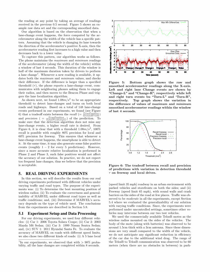
the reading at any point by taking an average of readingsreceived in the previous 0.5 second. Figure 5 shows an ex-ample raw data set and the corresponding smoothed data.Our algorithm is based on the observation that when a
lane-change event happens, the force computed by the ac-celerometer along the width of the vehicle has a specific pat-tern. Assuming that the vehicle is changing its lane towardsthe direction of the accelerometer’s positive X-axis, then theaccelerometer reading first increases to a high value and thendecreases back to a lower value.To capture this pattern, our algorithm works as follows.
The phone maintains the maximum and minimum readingsof the accelerometer (along the width of the vehicle) withina window of last 4 seconds. This duration of the window ishalf of the maximum duration taken by drivers to performa lane change1. Whenever a new reading is available, it up-dates both the maximum and minimum values, and checkstheir difference. If the difference is larger than a specifiedthreshold (τ), the phone reports a lane-change event, com-municates with neighboring phones asking them to engagetheir radios, and then moves to the Beacon Phase and trig-gers the lane localization algorithm.As shown next, we found 1.08m/s2 to be an appropriate
threshold to detect lane-changes and turns on both localroads and highways. Based on a total of 148 lane-changeevents performed in our experiments, we found (see Figure6) that a tradeoff exists between the recall (= TruePositive
GroundTruth)
and precision ( = TruePositiveTotalPredictions
) of the prediction. Tomake sure that the detection algorithm does not miss anylane-change events, a higher recall rate is desired. FromFigure 6, it is clear that with a threshold 1.08m/s2, 100%recall is possible with roughly 80% precision for local and60% precision for freeway. This ensures that whenever alane-change event happens, the smartphone is able to detectit. At the same time, it may also generate some false positiveevents (roughly 1 − 2 for every 5 predictions). However,since a more accurate relative localization is performed inPhase 2 and Phase 3, such false positives would not affectthe accuracy of our solution. In practice, we do not expecttoo frequent lane changes, thus we believe that the precisionis acceptable.
5. REAL DRIVING EXPERIMENTSIn this section, we will describe the results from our real
driving experiments performed with different vehicles undervarying traffic and road types. The purpose of the experi-ments was: (i) To determine the best mounting position ofwireless radios; (ii) To evaluate the correctness and general-izability of MARVEL under different road types as well astraffic conditions; and, (iii) Determine if MARVEL’s accu-racy depends on the type of vehicle used. The conclusionsfrom the experiments are described in Section 5.8.
5.1 Experiment Setup and Data ProcessingFor our driving experiments, we used four different vehi-
cles: (i) Car 1: 2006 Toyota Solara Coupe; (ii) Car 2: 2003Mazda M6 Sedan; (iii) Car 3: 1999 Nissan Sentra Sedan;and, (iv) SUV 1: 2011 Hyundai Santa Fe. To evaluate theaccuracy of MARVEL on roads with different speed limits,we also chose two different kinds of roads: (i) A 5 lane local
1In our experiments, we observed that with > 98% proba-bility, all the lane changes are completed within 8 seconds.
-1
0
1
2
3
0 10 20 30 40 50 60 70 80-1
0
1
2
3
0 10 20 30 40 50 60 70 80
Max Min Differences
-3
-2
-1
0
1
2
3
4
0 10 20 30 40 50 60 70 80Accele
rom
ete
r R
eadin
gs (
m/s
2)
Time (second)
Turn-R Change-L Change-R Change-L Change-R Change-L Noise
Raw DataSmoothed Data
-3
-2
-1
0
1
2
3
4
0 10 20 30 40 50 60 70 80Accele
rom
ete
r R
eadin
gs (
m/s
2)
Time (second)
Turn-R Change-L Change-R Change-L Change-R Change-L Noise-3
-2
-1
0
1
2
3
4
0 10 20 30 40 50 60 70 80Accele
rom
ete
r R
eadin
gs (
m/s
2)
Time (second)
Turn-R Change-L Change-R Change-L Change-R Change-L Noise-3
-2
-1
0
1
2
3
4
0 10 20 30 40 50 60 70 80Accele
rom
ete
r R
eadin
gs (
m/s
2)
Time (second)
Turn-R Change-L Change-R Change-L Change-R Change-L Noise-3
-2
-1
0
1
2
3
4
0 10 20 30 40 50 60 70 80Accele
rom
ete
r R
eadin
gs (
m/s
2)
Time (second)
Turn-R Change-L Change-R Change-L Change-R Change-L Noise-3
-2
-1
0
1
2
3
4
0 10 20 30 40 50 60 70 80Accele
rom
ete
r R
eadin
gs (
m/s
2)
Time (second)
Turn-R Change-L Change-R Change-L Change-R Change-L Noise-3
-2
-1
0
1
2
3
4
0 10 20 30 40 50 60 70 80Accele
rom
ete
r R
eadin
gs (
m/s
2)
Time (second)
Turn-R Change-L Change-R Change-L Change-R Change-L Noise-3
-2
-1
0
1
2
3
4
0 10 20 30 40 50 60 70 80Accele
rom
ete
r R
eadin
gs (
m/s
2)
Time (second)
Turn-R Change-L Change-R Change-L Change-R Change-L Noise
Figure 5: Bottom graph shows the raw andsmoothed accelerometer readings along the X-axis.Left and right lane Change events are shown by“Change-L” and “Change-R”, respectively while leftand right turn events bu “Turn-L” and ‘Turn-R”,respectively. Top graph shows the variation inthe difference of values of maximum and minimumsmoothed accelerometer readings within the windowof last 4 seconds.
0
20
40
60
80
100
0.8 1.2 1.6 2 2.4 2.8
Perc
enta
ge
Threshold (m/s2)
Recall-freewayRecall-local
Precision-freewayPrecision-local
Figure 6: The tradeoff between recall and precisionof predictions with variation in detection thresholdτ on freeway and local drives.
(speed limit 35 mph) roadway in an urban environment withparked vehicles and storefronts on both the sides; and (ii)Freeway (speed limit 65 mph), with sound walls and crashbarriers on the sides of the road at few places. Traffic was ob-served to be moderate in all the experiments, except Section5.4 where we evaluated the generalizability of our solutionwith varying traffic conditions. Since, the experiments wereperformed under uncontrolled settings, sometimes other ve-hicles may intervene between our two test vehicles.
We used the commercially available TelosB motes as thewireless radios mounted on the sides of the vehicles. Thebody of the mote (along with batteries) was observed to bearound 1.5cm thick with a 3cm antenna. Since these dimen-sions are very small compared to the width of the vehicle,we do not anticipate any significant reduction in efficiencyof the car due to the additional wind drag. The range ofthe TelosB to TelosB communication was observed to be 60meters (when there are no obstacles in between) in park-

ing lots. However, we could not measure the range duringdriving due to unavailability of appropriate equipment. Forthe purpose of experiments, instead of the smartphone, weused another TelosB mote connected with a laptop, insidethe vehicles, to collect RSSI readings from the TelosB motesmounted outside. To handle possible packet losses due tocollisions, TelosB motes send 5 localization beacons at a ran-dom spacing of 25-50ms. The path loss value for a link isthen computed by taking an average of the 5 values.We identify the problem of finding another vehicle’s po-
sition, among the six possible positions (see Figure 1), as asupervised classification problem and address it using ma-chine learning algorithms. For this, we used the RapidMinersoftware (version 5.1.104) [14] for training and testing. InRapidMiner, we chose the SVM’s implementation libSVMwith the SVM type set as C-SVC and kernel type as lin-ear. The values of C, cache size and epsilon were set to 0.0,80 and 0.001, respectively. We define the Classification ac-curacy as the percentage of the testing data for which therelative location is correctly predicted by the classificationmodel. For different experiments, we use different trainingand testing techniques to evaluate the accuracy of MAR-VEL. In some cases, we divide the collected data set intotwo parts, train on the first and test on the second. How-ever, in some other cases, we use independent test sets, i.e.,we train the system on one kind of data (e.g., for local roads)and test it on another kind of data (e.g., freeways).Errors in classification accuracy may arise due to a va-
riety of factors: (i) Presence of nearby driving vehicles onthe roadway and urban obstacles (store fronts, crash bar-riers, parked cars, sound walls etc.) may affect the valueof the signal strength; (ii) Transmissions from the roadsideWifi access points may affect the packet drop rate of thetransmitted beacons; (iii) Sometimes a car may straddle twolanes; and, (iv) Different vehicles may have different physi-cal profile (width, organization of machinery under the carhood etc.) which may affect the path loss values.The results shown in this paper are based on our 500 miles
of driving. During the driving experiments, one of the pas-sengers recorded the ground truth by manually recordingthe time and the relative vehicle positions while the driverschanged lanes at regular intervals. We randomly split thefinally collected data set into testing data set and trainingdata set. It was ensured that each of the 6 classes (corre-sponding to six different relative positions from Figure 1)have equal amount of data in both the training sets and thetesting sets.
5.2 Determining the best configurationIn this experiment, we varied the number and positions
of radios on the vehicle to determine the configuration thatmaximizes the localization accuracy. In our experiment, weexplored 21 candidate configurations on the exterior of a carto mount the TelosB motes. Figure 7 shows four such pos-sible configurations along with their labels and accuracies.For rest of the results, please refer to our technical report[13]. In each driving test, we mounted the specified num-ber of radios on the two cars. The total duration of drivingfor each test was around 60 minutes with about 30 minutesof local driving and 30 minutes of freeway driving. In thissubsection, we used four types of driving data for each radioposition combination: (i) Data between two sedans on localroads; (ii) Data between two sedans on freeway; (iii) Data
99.7%
A
94.7%
B
97.7%
C
91.8%
D
Figure 7: The different combinations of placementof the wireless radios and the corresponding relativelane localization accuracy. A and B have four radiosattached while C and D have 3 radios. The classi-fier from configuration A has the highest predictionaccuracy.
between the coupe and SUV on local roads; and, (iv) Databetween the coupe and SUV on freeway. The data was thendivided into equal-sized training set and a testing set.
We observed that when four radios are placed verticallyabove the four wheels on the vehicle’s body, we get the max-imum accuracy of 99.78%. In the later evaluations, we onlyuse configuration A, unless mentioned otherwise. Also, fromFigure 7, we can observe that using more radios increasesthe classification accuracy since more radios capture moreinformation about the relative locations of vehicles. Theresults of the experiment also indicate that the position ofthe radios affect the accuracy of the classifier. For exam-ple, C and D both have three radios but their accuracy issignificantly different.
5.3 Evaluation with varying road typesThe purpose of this experiment was to evaluate the gen-
eralizability of MARVEL with varying road types: (i) Localroads; and, (ii) Freeways. The speed limit on local roadsand freeway were 35 MPH and 65 MPH, respectively. Thetraffic was observed to be moderate when collecting the twodata sets. We used the coupe and the SUV’s driving dataas well as the two sedan’s driving data in this experiment.After the experiment, we created a local driving data setLocal and a freeway driving data set Freeway.
We first used data from Local to train an SVM classifier.When tested on data from Freeway, the classifier’s accuracywas found to be 97.33%. In the next test, we trained anotherSVM classifier using Freeway data and tested it on Localdata. This time, the classifier gave an accuracy of 99.39%.This high classification accuracy indicates that the path losspatterns on local roads and freeways are similar and thattraining is independent of road type and speed.
5.4 Evaluation under varying traffic conditionsIn this experiment, we want to determine whether MAR-
VEL is robust to variations in traffic conditions, and thendecide whether we need to include the driving data of dif-ferent traffic conditions to train the classifier. For this, wecreated a heavy traffic data set called Heavy and a lighttraffic data set called Light. Heavy contains the data be-tween the coupe and SUV on a mix of busy local roads andbusy freeways. The same two vehicles were also driven underlight traffic conditions to create the dataset Light.
We used Heavy to train an SVM classifier, and then on

testing it with Light, the classification accuracy was foundto be 38.68%. In the next test, we used Light as the trainingset. When tested by Heavy, the new classifier had accuracyof 25.22%. In both cases, the accuracy is quite low. Thisindicates that the radio’s path loss pattern in light and heavytraffic conditions are different. This is because in heavytraffic, frequently there are multiple other vehicles betweenthe two testing vehicles. This result is consistent with ourobservation that the body of a car can affect the path lossof the wireless radio signal.However, we find that splittingHeavy into two equal sized
sets Heavy1 and Heavy2, training the classifier on Heavy1and testing it on Heavy2, increases the classification accu-racy to 96.91%. Similarly, if Light is split into two setsLight1 and Light2, with training performed on one andtesting on the other, it also increases the classification accu-racy to 99.84%. This result indicates that both heavy trafficdata and light traffic data have clear and consistent patterns.Therefore, to estimate the relative position in different traf-fic conditions, one way is to include the traffic condition asan input to the classifier.We created a mixed traffic data set Mix by combining
equal amounts of data from both Heavy and Light. Thenwe split Mix into two equal sized data sets Mix1 and Mix2,trained the SVM classifier on Mix1 and tested it separatelyon Mix2, Light2 and Heavy2. This classifier’s accuracywas observed to be 97.21%, 95.73% and 99.11%, respectively.The mixed traffic condition classifier has high accuracy indi-cating that for high accuracy classification in various trafficconditions, it is useful to train it under both light and heavytraffic conditions. This removes the requirement to providethe traffic condition information as an input.
5.5 Evaluation with variation in vehicle typesIn this experiment, we tested how the body of a car affects
the performance of the classifier. We call the data collectedby using the coupe and the SUV on both local roads andfreeways as SUV Data, and the data collected using twosedans on same roads as SedanData. For both types ofroads, the traffic was observed to be moderate.We first use SedanData to train an SVM classifier, and
upon testing it with SUV Data, we observed an accuracy of88.32%. Similarly, in the next test, we trained the SVMclassifier with SUV Data and tested it using SedanDataand observed the accuracy to be 93.50%. Compared withthe results in Section 5.2, the results here are around 10%lower. This indicates that different types of vehicle bodiescreate different signal strength patterns; however, the vari-ation in the patterns is much smaller than the variation dueto different traffic conditions. We can see from the result inSection 5.2 that when we include different types of vehiclesinto the training set, the accuracy was very high (99.78%).This indicates that the classification model does not have abias problem with respect to vehicle type, therefore, it is notrequired to provide vehicle body as an input to the model.
5.6 Evaluation with variation in wireless ra-dio position
As discussed in Section 5.2, the best position for mountingthe wireless radios is above the wheels. However, constraintson the body of the vehicle and human errors may lead toinstallations in positions that are not necessarily optimal.In this experiment, we studied the sensitivity of the results
Table 1: Test results of the classifier trained by mix-ing all the driving data.
Testing data set AccuracyMixed data 96.8%Two sedans, Local, Moderate traffic 98.5%Two sedans, Freeway, Moderate traffic 97.9%Coupe and SUV, Local, Moderate traffic 97.7%Coupe and SUV, Freeway, Moderate Traffic 99.4%Coupe and SUV, Local, Heavy Traffic 92.8%Coupe and SUV, Freeway, Heavy Traffic 95.7%Two sedans on a freeway with curves 94.0%
with respect to the device position. This time, for collect-ing data, we drove two sedans on local as well as freewayand collected three data sets: (i) Correct : Radios mountedat correct position with correct orientation; (ii) Incorrect10 :Radios mounted anywhere within 10 cm of the correct po-sition with random orientation; and, (iii) Incorrect20 : Ra-dios mounted anywhere within 20 cm of the correct positionwith random orientation. We then divided Correct in twoequal parts, Correct1 and Correct2. By training the SVMclassifier on Correct1, and testing on Correct2, Incorrect10and Incorrect20 we obtained accuracies of 99.2%, 98.0% and96.5%, respectively. Next, we mixed all the three data setsto get Mix and used it for training. When tested on Cor-rect, Incorrect10 and Incorrect20, the SVM classifier gaveaccuracies of 99.1%, 98.4% and 97.3%, respectively.
5.7 Mix all types of driving data togetherIn this section, we trained the classifier on a data set com-
bined from all driving tests and evaluated its accuracy ondifferent types of driving data. In the combined trainingset, we include: (i) the two sedan’s local and freeway driv-ing data in moderate traffic; and, (ii) the coupe and SUV’slocal and freeway driving data under both moderate andheavy traffic conditions. The testing was done on differentsets of driving data separately as well as on another dataset from a drive on a curved freeway. Due to unavailabilityof a local long enough road with multiple lanes and curves,we skipped testing the classifier on curved local roads. FromTable 1, we can see that for all the cases, the mixed mode’saccuracy is at least 92.8%. When testing on curved free-ways, the accuracy is slightly lower, as the classifier predictssome of the same lane cases as left lane or right lane. Theoverall accuracy was observed to be 96.8%. This result con-firms that MARVEL is robust to most of the variations indriving cases.
5.8 Conclusion from the experimentsFrom the experiment results (Section 5.2), we can make
the following conclusions: (i) The best configuration amongall the configurations we tested is A (Figure 7), where thefour radios are placed above the four wheels of the vehicle;(ii) Driving speed does not affect the accuracy significantly;(iii) Heavy traffic conditions and light traffic conditions havedifferent path loss patterns, but their own patterns are con-sistent which allows us to train the model with mixed trafficdata and still get high classification accuracy; (iv) The clas-sifier’s prediction accuracy varies with variation in vehicle’sbody but after combining the training data of different carbodies, it is possible to achieve high prediction accuracy;

and, (v) Our design is robust to placement errors of the ra-dios. Finally, after mixing all the training data and testingit individually on each of the testing data sets, we observedthat the classifier has 96.8% pediction accuracy when testedunder moderate traffic conditions. In heavy traffic conditionand curved drive, the accuracy will decrease, but the overallaccuracy remains above 92.8%.
6. INCREASING ROBUSTNESS THROUGHAGGREGATION
In Section 3, we discussed how the radios on the vehiclecan be used to determine the relative location of two vehi-cles. However, sometimes it may lead to incorrect results.In this section, we explain how the accuracy of localizationcan be further increased through aggregation, e.g., if V1 isleft of V2 and V2 is left of V3, then it is possible to inferthat V1 is also left of V3. Similar kind of aggregation canbe used for front and rear relationships. Accuracy of rela-tive localization can be improved by applying aggregationrules separately to left-same-right and front-rear relation-ships between neighboring vehicles. Consequently, in thissection, we discuss two algorithms. The first one improvesthe accuracy of lane localization while the second improvesfront and rear localization accuracy. Both the algorithmsare distributed in nature and are executed by every vehiclein the network. Whenever the phone (or the correspond-ing vehicle) determines its relative position with respect tosome neighboring vehicle, it executes both the algorithmsto further improve the robustness. However, desinging anaggregation algorithm that improves localization accuracyinvolves the following challenges: (i) To avoid dependenceon a centralized server, it is preferable to use a distributedalgorithm; (ii) The set of neighbors of a vehicle may changewith time, making it hard to find a fixed set of aggregatingvehicles; and, (iii) The relative location determined by theSVM classifier may be incorrect in some cases.
6.1 Aggregating relative lane localization in-formation
To improve the accuracy of left-same-right relationship,we assign every vehicle (Vi) a coordinate system (Ci), a vir-tual lane number (Li) corresponding to that coordinate sys-tem and a probability (αi) that Vi is in virtual lane Li.Virtual lane numbers are comparable among vehicles thatbelong to the same coordinate system, i.e., any two vehiclesthat belong to the same coordinate system have the samevirtual lane numbers iff they are in the same physical lane ofthe roadway. Similarly, a vehicle on the left side has highervirtual lane number than a vehicle on the right side if both ofthem belong to same coordinate system. The virtual lane lo-cation is computed using the relative locations with respectto multiple neighbors that belong to the same coordinatesystem. Thus, the usage of the coordinate system can alsofix errors that may arise in relative localization. Further, italso allows two neighboring vehicles that have never directlycommunicated with each other before, to easily determineif their relative lane location can be computed by simplycomparing their virtual lane numbers.A coordinate system Ca is denoted by the tuple (Ta, Ia)
where Ta is the timestamp when the coordinate system wascreated and Ia is the ID of the vehicle that created the coor-dinate system. A coordinate system Ca is said to be smaller
than coordinate system Cb if one of the following conditionsis true: (i) Ta < Tb; or, (ii) Ta = Tb and Ia < Ib. To ensurethat the virtual lane numbers of vehicles is comparable, ouralgorithm tries to move all vehicles to the same coordinatesystem. For this, in our algorithm every vehicle joins thesmallest coordinate system among all its neighbors. Notethat smallest is preferred over largest since a new vehiclejoining an existing coordinate system will require only thatvehicle to change its coordinate system.
A vehicle may also create a new coordinate system when-ever its virtual lane number becomes unknown. For exam-ple, this may happen: (i) When the app on the phone isstarted; (ii) When the app detects that the vehicle is in mo-tion after being parked for more than Tstop time; or (iii) Ifthe data from the accelerometer indicates a possible turnevent or a lane change event2. The creation of a new coor-dinate system after a turn event ensures that the coordinatesystem of the turning vehicle is larger than those of the ve-hicles that are present on the new road. This forces theturning vehicle to join the coordinate system of the othervehicles. Thus, only one vehicle may change its coordinatesystem, instead of all the vehicles that were present on thenew road. This not only reduces the communication over-head but also makes the system more stable.
Upon creation of a new coordinate system with the currenttimestamp and its own ID, the vehicle (say Vi) initializes itslane number (Li) in the new coordinate system to be 1 andthe corresponding probability (αi) as 1. After initializingits coordinate system, Vi may seek to join the coordinatesystem of another vehicle. For this, it communicates withall its neighbors, to obtain the information of their currentcoordinate systems, their lane numbers and the correspond-ing probability values. The vehicle then joins the smallestcoordinate system among all its neighbors (Lines 1-2 of Al-gorithm 1). This ensures that eventually all neighboringvehicles will belong to the same coordinate system, therebyincreasing the chances that their virtual lane numbers arecomparable. When joining the new coordinate system, Vi
also determines its lane number with the help of its neigh-bors (denoted by Slow) that are in the smallest coordinatesystem (Lines 3-19). Then, Vi determines its relative loca-tion with respect to all vehicles in Slow using the algorithmdiscussed in Section 3 (Line 6). Then, it proceeds to com-pute its lowest possible lane (min) and highest possible lane(max) numbers (Line 7) which are one lower and one higherthan the lowest and highest lane numbers of all vehicles inSlow, respectively. The vehicle may be assigned a virtuallane number of min only if it is to the left of all its neigh-boring vehicles.
Then, for every lane among the possible lanes from minto max, it computes the confidence that the vehicle is lo-cated in that lane (Lines 8-17). To compute the confidenceof being in a particular lane (say l), it computes the relativelocation of l with the lane number of vehicle Vj (Lines 11-16). This confidence is computed over all vehicles and theirsum (confil) reflects the confidence that Vi is in l basedon information of all vehicles in Slow (Line 17). Here c isthe output of the SVM based classifier (see Section 3) andits value lies between 0 and 1. Finally, the lane that maxi-mizes the confil is designated as the lane number of Vi and
2Since it may not be possible to distinguish a turn eventfrom a lane change event as well as to determine how manylanes the vehicle actually changed.

its probability value (αi) is also updated by normalizing itacross all possible lanes (Lines 18-19).It is also possible that two vehicles that are physically
spearated by multiple lanes are assigned consecutive virtuallane numbers. This may later cause conflicts when a newvehicle moves to the lane in between these two vehicles. Totake into account such cases and for increased robustness,each vehicle in our algorithm also invokes Algorithm 1 peri-odically to update its virtual lane number.Since each vehicle now has a virtual lane number, two ve-
hicles can now arrive at a more accurate result for their rel-ative localization by just comparing their virtual lane num-bers. Also, since each virtual lane number corresponds toa physical lane, therefore the number of virtual lanes arelimited by the number of physical lanes on the road.
Algorithm 1: For a given vehicle (Vi), distributed algo-rithm for updating coordinate system (Ci), lane number(Li) and corresponding probability (αi) for Vi
1 For every neighbor Vj , obtain Vj ’s coordinate system (Cj),Vj ’s most probable virtual lane number (Lj) and probabilitythat Vj is in Lj (αj)
2 Clow ← arg minj:Vj is a neighbor of Vi
Cj
3 Slow ← Set of neighboring vehicles that are in Clow
4 if Clow ≤ Ci then5 Ci ← Clow, Li ← φ6 Determine relative lane location with respect to each
vehicle in Slow.7 min← min
j:Vj∈Slow
Lj − 1,max← maxj:Vj∈Slow
Lj + 1
8 for l = min to max do9 confil ← 0
10 for all Vehicle Vj ∈ Slow do11 if Lj − l > 0 then12 c←Confidence that relative location of Vj
with respect to Vi is left13 if Lj − l = 0 then14 c←Confidence that relative location of Vj
with respect to Vi is same lane15 if Lj − l < 0 then16 c←Confidence that relative location of Vj
with respect to Vi is right17 confil ← confil + αj × c18 maxLane← argmax
iconfii
19 Li ← maxLane, αi ← confimaxLane∑maxl=min
confil
6.2 Aggregating front-back localization infor-mation
Similarly, in order to improve the accuracy of the front-back localization, each vehicle obtains relationship informa-tion with its neighbors. Using that information and its ownrelative position with respect to its neighbors, it constructs arelationship graph G = (W,E) where W is the set of vehicles(See Algorithm 2). Further, there is an edge from vehicle Va
to Vb iff Va believes that Vb is in its front3. Presence of adirected cycle in G implies that relative location for at leastone pair of vehicles is incorrect (See [13] for proof). There-fore, by removing cycles from G, Algorithm 2 increases theaccuracy of relative localization.
3Equivalent to saying that Vb believes that Va is in rearsince the vehicle that computes relative location passes onthe result to the other vehicle (Section 3.3.3)
Since counting the number of cycles in a graph is an NP-Hard problem (See [13] for proof), therefore, we define aheurisitcal metric β(G) that captures the number of cyclesin G. To determine if a directed edge (Vi, Vj) is a part ofsome cycle, we only need to check if Vi is reachable from Vj .
β(G) = {|e : e ∈ E and e is part of some directed cycle|}
To remove cycles from G without losing any relative lo-cation information, Algorithm 2 reverses edges in G untilG becomes acyclic. For this, at each step, it iteratively re-verses the edge that reduces the number of cycles in G bythe largest amount. Reversing an edge (Va, Vb) indicatesthat based on information of neighboring vehicles, it is morelikely that Va is actually in front of Vb. To minimize thenumber of edges reversed, Algorithm 2 first tries to find asingle edge that can be reversed to reduce the number of cy-cles (Lines 5-11). However, it is possible that it is not able tofind any such edge even though the graph is cyclic. In thatcase, it picks a vertex and reverses all the incoming edges(Lines 15-19) or all the outgoing edges (Lines 20-24). Algo-rithm 2 performs this search over all vertices and performsthe operation on the vertex that maximizes the number ofcycles reduced (Lines 13-25). It can be shown that Algo-rithm 2 eventually terminates and has a polynomial timecomplexity (For proof, see [13]).
Algorithm 2: For a given vehicle (Vi), distributed al-gorithm for updating front-back relationship of Vi withrespect to its neighbors
1 G = (W,E)← Front-back graph based on neighborhood infowhere
2 W ← {Vi}∪ Neighbors of Vi
3 E ← {(Va, Vb) : Va believes that Vb is in its front }4 while β(G) > 0 do5 maxdiff ← 0, edgeToReverse← φ6 for all e ∈ E do7 E′ ← E\{e} ∪ {e}, G′ ← (W,E′)8 if β(G)− β(G′) > maxdiff and e is not a part of
some directed cycle in G′ then9 maxdiff ← β(G)− β(G′), edgeToReverse← e
10 if maxdiff > 0 then
11 E ← E\{edgeToReverse} ∪ {edgeToReverse}12 else13 edgesToReverse← φ14 for all Vi ∈W do15 F ← {(Vj , Vi) for some Vj ∈W}16 F ←Obtained after reversing all edges in F
17 E′ ← E\F ∪ F , G′ ← (W,E′)18 if β(G)− β(G′) > maxdiff then19 maxdiff ← β(G)− β(G′),
edgesToReverse← F20 F ← {(Vi, Vj) for some Vj ∈W}21 F ←Obtained after reversing all edges in F
22 E′ ← E\F ∪ F , G′ ← (W,E′)23 if β(G)− β(G′) > maxdiff then24 maxdiff ← β(G)− β(G′),
edgesToReverse← F25 E ← E\{edgesToReverse} ∪ {edgesToReverse}
7. SIMULATIONSIn Section 5, we described the experiment results obtained
on a variety of vehicles. However, evaluating the behaviorand performance of our algorithm for a larger set of vehi-cles was labor intensive as every vehicle requires one driver

0
2
4
6
8
0 5 10 15 20 25
Perc
enta
ge P
ackets
Lost
Number of Neighbors
Percentage Packets Lost
(a) Percentage Packets Lost
96
97
98
99
100
0 5 10 15 20 25
Pre
dic
tion P
erc
enta
ge A
ccura
cy
Number of Neighbors
After AggregationBefore Aggregation
(b) Localization accuracy be-fore and after performing ag-gregations
Figure 8: Simulation results with varying number ofneighbors.
and one passenger to record the ground truth. So, we per-formed trace-driven simulations using ns-3[1] and SUMO[4].SUMO is a simulator for VANETs which given a road net-work, generates a pre-determined number of trips for ve-hicles. For each trip, it chooses a random starting point,a random ending point and generates a route for the vehi-cle completing that trip. SUMO is a microscopic-level roadtraffic simulator which implies that SUMO models multi-ple lanes in the roadways and vehicles in SUMO performautomatic lane-changes and overtaking of vehicles as theymove from their starting point to their ending point in themap. The objectives of the simulations were as follows: (i)To determine the increase in accuracy achieved by using ag-gregation algorithms; and, (ii) To determine the packet lossrate and its affect on accuracy when multiple vehicles arerunning MARVEL.For our simulations, we chose a 3 miles × 3 miles area
around downtown of Austin4. Further, we used SUMO togenerate 1000 trips (or vehicles) and their correspondingroutes. The simulation was executed for 900 seconds whichwas enough for every vehicle to reach its destination. Theoutput of SUMO (position of every vehicle at each instant oftime) was used for generating the locations of correspondingnodes in ns-3.In ns-3, every vehicle consisted of 5 nodes: a smartphone
and the 4 wireless radios. The mobility of the 5 nodes isgenerated from the SUMO’s output. The smartphones sendUDP discovery beacons every 10 seconds that are heard byneighboring smartphones. The range of radio to radio com-munication was set to 65 meters while the range of smart-phone to smartphone communication was set to 100 meters.The wireless radios transmitted localization beacons when
directed by the smartphone. To simulate the effect of ve-hicle’s body and the neighboring urban structures (parkedcars, other vehicles and store fronts) on the signal strength,we took the signal strength values at the receiving wirelessradios from the data obtained through experiments corre-sponding to the ground truth location of the 2 vehicles.However, the packets from one wireless radio (or smart-phone) to another were still dropped by ns-3 if some otherneighboring node was also observed to be transmitting at thesame time. Similar to experiments, here also every wirelessnode transmitted 5 localization beacons at random spacingsof 25-50 ms. The smartphone computed the relative locationof its vehicle with respect to neighboring vehicles by pass-
4Randomly chosen city
ing the 16 averaged RSSI values to the SVM classifier. Forthe simulations, we assumed that the smartphone triggerslane change events with 100% recall and 60% precision (SeeSection 4).
Simulation Results: Figure 8a shows that packet lossrate increases with increase in number of neighbors. Theaverage packet loss rate across all nodes was observed to be2.3%. Since, in MARVEL, radio nodes broadcast lane dis-covery beacons multiple times, it is expected that this lowloss rate would not decrease the accuracy. However, withincrease in number of neighbors, it is possible for MARVELto increase accuracy by making use of aggregation. Figure8b shows the variation in localization accuracy before andafter we performed aggregation using the two algorithms.With aggregation, MARVEL is able to improve the local-ization accuracy to 99% when the number of neighbors isvery high. When number of neighbors is low, aggregatinginformation across vehicles provides limited benefit. Overall vehicles in the simulation, we observed that aggregationimproved accuracy to 98%.
8. DISCUSSION AND FUTURE WORKIn this section, we discuss some mechanisms that can make
MARVEL more accurate and practical.
8.1 Increasing lifetime of wireless radiosBy using the accelerometer of the phone to trigger the rel-
ative localization algorithm, we have been able to avoid pe-riodic triggering of wireless radios, thereby increasing theirlifetime. Results from our experiments and simulations showthat the standard TelosB motes exhibit a battery lifetime ofat least 6 months for an average of 2 hours daily drivingand a maximum reaction time of 1 second after the lanechange event is triggered (See [13] for details). To removethe dependence on batteries, the possibility of connectingthe wireless radios directly to the vehicle’s power supplycan also be explored.
8.2 Incremental DeploymentMARVEL can determine relative location only if both ve-
hicles are equipped with wireless radios. It cannot determinethe relative location if only one of the vehicles is equippedwith radios. However, MARVEL can provide incrementalbenefit to vehicles that are equipped with 4 radios. In USA,FCC has already reserved 75 MHz of spectrum for Dedi-cated Short Range inter-vehicle Communication (DSRC). Itis expected that in the future, all vehicles will be equippedwith at least one antenna for DSRC. Our experiments showthat if one of the vehicles is equipped with only one antenna(located on the vehicle’s body near the front passenger sidewheel) and the other with 4 antenna, MARVEL correctlypredicts the relative location with 64% accuracy. Therefore,as DSRC becomes more widespread, vehicles with 4 anten-nas would be able to use MARVEL with 64% and 96.8%accuracy when they encounter other vehicles with a singleantenna and with four antennas, respectively5. Using simu-lations, we also observed that if 50% of the vehicles have 1antenna while the other 50% have 4 antennas, then averagelocalization accuracy was 87% for one antenna-four antenna
5This is under the assumption that the location of DSRCantenna is on the side of the vehicle. A centrally locatedantenna may give different results.

vehicle pairs and 96% for four antenna-four antenna vehi-cle pairs. Thus, with aggregation, it is possible to achievehigher localization accuracy even when all vehicles are notequipped with four radios.
8.3 Training CostTo achieve higher localization accuracy, it is beneficial to
train MARVEL for the specific vehicle. As we saw in Section5.5, it still provides an accuracy of 90% when trained on a ve-hicle with different physical profile. Also, in our experimentswe saw that testing a classifier on sedan-sedan pair that istrained with sedan-coupe pair still gives 96% accuracy. Thisimplies that it is not necessary to train MARVEL separatelyfor vehicles that have similar physical profiles, although toget higher accuracy it is beneficial to train MARVEL on onlythose vehicles that have significantly different profiles.
9. CONCLUSIONIn this paper, we proposed a novel antenna diversity based
solution called MARVEL, for determining the relative loca-tion of two vehicles on roadways. Relative location infor-mation has the potential to not only enhance the drivingexperience by providing relevant alerts but also reduce thechance of collisions. MARVEL has low cost and is easy toinstall on newer as well as exisiting vehicles. Results fromour driving experiments performed under varying conditionsshow that MARVEL predicts relative location of two vehi-cles with an average accuracy of 96.8%. MARVEL is ableto determine the relative position of vehicles that are notin the immediate neighborhood, thereby giving the vehicledriver more time to react. To reduce energy consumption ofwireless radios and to reduce the number of packets trans-mitted, we also proposed using the phone’s accelerometer totrigger the localization algorithm. We presented two algo-rithms that increase the localization accuracy by aggregatinginformation across multiple vehicles. Our trace-driven sim-ulations show that by aggregating information, MARVEL isable to increase the localization accuracy to 98%.
10. ACKNOWLEDGEMENTSThis material is based upon work partially supported by
the National Science Foundation under Grants CNS-0721817and CNS-0831919. We would also like to thank Prof. MarcoGruteser for shepherding the paper.
11. REFERENCES[1] The ns-3 network simulator. http://www.nsnam.org/.
[2] Valeo Raytheon Systems. www.valeo.com.
[3] AASHTO. A Policy on Geometric Design of Highwaysand Streets. 2001. pp 384–386.
[4] M. Behrisch, L. Bieker, J. Erdmann, andD. Krajzewicz. SUMO - Simulation of UrbanMObility: An Overview. In Proc. of ThirdInternational Conference on Advances in SystemSimulation (SIMUL), 2011.
[5] C. M. Bishop. Pattern Recognition and MachineLearning. Springer, 2007.
[6] R. Chellappa, G. Qian, and Q. Zheng. VehicleDetection and Tracking Using Acoustic and VideoSensors. In Proc. of IEEE Int’l Conf. Acoustic, Speech,and Signal Processing, 2004.
[7] H. Y. Cheng, B. S. Jeng, P. T. Tseng, and K. C. Fan.Lane Detection with Moving Vehicles in the TrafficScenes. IEEE Transactions on IntelligentTransportation Systems, 7(4):571–582, 2006.
[8] P. Dutta and D. Culler. Practical AsynchronousNeighbor Discovery and Rendezvous for MobileSensing Applications. In Proc. of ACM SenSys, pages71–84, 2008.
[9] Garmin. What is GPS.http://www8.garmin.com/aboutGPS/index.html.
[10] A. Gern, U. Franke, and P. Levi. Advanced LaneRecognition-Fusing Vision and Radar. In Proc. ofIEEE Intelligent Vehicles Symposium, 2000.
[11] F. Heimes and H. Nagel. Towards ActiveMachine-Vision-Based Driver Assistance for UrbanAreas. Int’l J. Computer Vision, 50:5–34, 2002.
[12] A. Kandhalu, K. Lakshmanan, and R. R. Rajkumar.U-connect: A Low-Latency Energy-EfficientAsynchronous Neighbor Discovery Protocol. In Proc.of ACM IPSN, 2010.
[13] D. Li, T. Bansal, Z. Lu, and P. Sinha. MARVEL:Multiple Antenna based Relative Vehicle Localizer.Technical report, Ohio State University, 2012.OSU-CISRC-6/12-TR12.
[14] I. Mierswa, M. Wurst, R. Klinkenberg, M. Scholz, andT. Euler. YALE: Rapid Prototyping for Complex DataMining Tasks. In Proc. of ACM SIGKDD, 2006.
[15] P. Mohan, V. N. Padmanabhan, and R. Ramjee.Nericell: Using Mobile Smartphones for RichMonitoring of Road and Traffic Conditions. In Proc. ofACM EMNETS, 2008.
[16] NHTSA. Evaluation of Lane Change CollisionAvoidance Systems Using the National AdvancedDriving Simulator. DOT HS 811 332, U.S.Department of Transportation, May 2010.
[17] G. Padmavathi, D. Shanmugapriya, and M. Kalaivani.A Study on Vehicle Detection and Tracking UsingWireless Sensor Networks Open Access. WirelessSensor Network, 2(2):173–185, 2010.
[18] S. Park, K. Kim, S. Kang, and K. Heon. A NovelSignal Processing Technique for Vehicle DetectionRadar. IEEE MTT-S Int’l Microwave Symp. Digest,2003.
[19] J. P. Piran, G. R. Murthy, and G. P. Babu. VehicularAdhoc and Sensor Networks: Principles andChallenges. International Journal of Ad hoc, Sensorand Ubiquitous Computing, 2(2):38–49, 2011.
[20] C. Wang, C. Thorpe, and A. Suppe. Ladar-BasedDetection and Tracking of Moving Objects from aGround Vehicle at High Speeds. In Proc. of IEEEIntelligent Vehicle Symp., 2003.
[21] C. C. Wang, S. S. Huang, and L. C. Fu. DriverAssistance System for Lane Detection and VehicleRecognition with Night Vision. In Proc. of IEEEIntelligent Robots and Systems, 2005.
[22] J. Yang, S. Sidhom, G. Chandrasekaran, T. Vu,H. Liu, N. Cecan, Y. Chen, M. Gruteser, and R. P.Martin. Detecting Driver Phone Use Leveraging CarSpeaker. In Proc. of ACM MobiCom, 2011.


![Electrically Small Antenna Design - ITS Small Antenna Design ... Example : microstrip patch antenna Ground plane ... Bandwidth [MHz] relative patch size f r =1 GHz](https://img.pdfslide.us/doc/110x75/5aa70bfa7f8b9a6d5a8bcb7d/electrically-small-antenna-design-its-small-antenna-design-example-microstrip.jpg)