Embed Size (px)
Citation preview
Martin® Hurricane Air Cannon & Martin® Multi Valve Air Cannon
Operator’s Manual M3737
Martin® Multi Valve Air Cannon
35L
70L
150L
Go to Martin® Hurricane Air Cannon web page
Go to Martin® Multi Valve Air Cannon web page
ImportantMARTIN ENGINEERING HEREBY DISCLAIMS ANY LIABILITY FOR: DAMAGE DUE TO CONTAMINATION OF THE MATERIAL; USER’S FAILURE TO INSPECT, MAINTAIN AND TAKE REASONABLE CARE OF THE EQUIPMENT; INJURIES OR DAMAGE RESULTING FROM USE OR APPLICATION OF THIS PRODUCT CONTRARY TO INSTRUCTIONS AND SPECIFICATIONS CONTAINED HEREIN. MARTIN ENGINEERING’S LIABILITY SHALL BE LIMITED TO REPAIR OR REPLACEMENT OF EQUIPMENT SHOWN TO BE DEFECTIVE.Observe all safety rules given herein along with owner and Government standards and regulations. Know and understand lockout/tagout procedures as defined by American National Standards Institute (ANSI) z244.1-1982, American National Standard for Personnel Protection - Lockout/Tagout of Energy Sources - Minimum Safety Requirements and Occupational Safety and Health Administration (OSHA) Federal Register, Part IV, 29 CFR Part 1910, Control of Hazardous Energy Source (Lockout/Tagout); Final Rule.
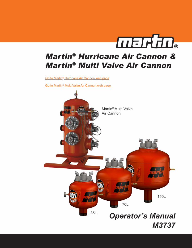
The following symbols may be used in this manual:
DANGER!
Danger: Immediate hazards that will result in severe personal injury or death.
WARNING!
Warning: Hazards or unsafe practices that could result in personal injury.
CAUTION!
Caution: Hazards or unsafe practices that could result in product or property damages.
IMPORTANTImportant: Instructions that must be followed to ensure proper installation/operation of equipment.
NOTENote: General statements to assist the reader.
Martin Engineering M3737-11/12 i Martin® Hurricane Air Cannon
Table of Contents
Section PageList of Figures . . . . . . . . . . . . . . . . . . . . . . . . . . . . . . . . . . . . . . . . . . . . . . . . . . . . . . . . . . . . . . iiIntroduction . . . . . . . . . . . . . . . . . . . . . . . . . . . . . . . . . . . . . . . . . . . . . . . . . . . . . . . . . . . . . . . . 1
General . . . . . . . . . . . . . . . . . . . . . . . . . . . . . . . . . . . . . . . . . . . . . . . . . . . . . . . . . . . . . . . . 1Operation . . . . . . . . . . . . . . . . . . . . . . . . . . . . . . . . . . . . . . . . . . . . . . . . . . . . . . . . . . . . . . 1Tank data . . . . . . . . . . . . . . . . . . . . . . . . . . . . . . . . . . . . . . . . . . . . . . . . . . . . . . . . . . . . . . 2Model and serial numbers . . . . . . . . . . . . . . . . . . . . . . . . . . . . . . . . . . . . . . . . . . . . . . . . . 2Specifications . . . . . . . . . . . . . . . . . . . . . . . . . . . . . . . . . . . . . . . . . . . . . . . . . . . . . . . . . . . 2Required accessories . . . . . . . . . . . . . . . . . . . . . . . . . . . . . . . . . . . . . . . . . . . . . . . . . . . . . 2References . . . . . . . . . . . . . . . . . . . . . . . . . . . . . . . . . . . . . . . . . . . . . . . . . . . . . . . . . . . . . 3Safety . . . . . . . . . . . . . . . . . . . . . . . . . . . . . . . . . . . . . . . . . . . . . . . . . . . . . . . . . . . . . . . . . 3Materials required . . . . . . . . . . . . . . . . . . . . . . . . . . . . . . . . . . . . . . . . . . . . . . . . . . . . . . . 3
Before Installing Air Cannon. . . . . . . . . . . . . . . . . . . . . . . . . . . . . . . . . . . . . . . . . . . . . . . . . . . 4Installing Air Cannon . . . . . . . . . . . . . . . . . . . . . . . . . . . . . . . . . . . . . . . . . . . . . . . . . . . . . . . . 6
Installing mounting plate . . . . . . . . . . . . . . . . . . . . . . . . . . . . . . . . . . . . . . . . . . . . . . . . . . 6Connecting air cannon to mounting plate . . . . . . . . . . . . . . . . . . . . . . . . . . . . . . . . . . . . . 10Installing flexible hoses and hard pipe. . . . . . . . . . . . . . . . . . . . . . . . . . . . . . . . . . . . . . . . 11Installing restraining cable . . . . . . . . . . . . . . . . . . . . . . . . . . . . . . . . . . . . . . . . . . . . . . . . . 14Mount Martin® Multi Valve Air Cannon System . . . . . . . . . . . . . . . . . . . . . . . . . . . . . . . 15Connecting air supply to air cannon. . . . . . . . . . . . . . . . . . . . . . . . . . . . . . . . . . . . . . . . . . 16
After Installing Air Cannon . . . . . . . . . . . . . . . . . . . . . . . . . . . . . . . . . . . . . . . . . . . . . . . . . . . . 20Maintenance. . . . . . . . . . . . . . . . . . . . . . . . . . . . . . . . . . . . . . . . . . . . . . . . . . . . . . . . . . . . . . . . 22
Every month . . . . . . . . . . . . . . . . . . . . . . . . . . . . . . . . . . . . . . . . . . . . . . . . . . . . . . . . . . . . 22Every year or 50,000 firings. . . . . . . . . . . . . . . . . . . . . . . . . . . . . . . . . . . . . . . . . . . . . . . . 23Martin® Hurricane Air Cannon Valve Assembly Replacement. . . . . . . . . . . . . . . . . . . . . 24
Troubleshooting . . . . . . . . . . . . . . . . . . . . . . . . . . . . . . . . . . . . . . . . . . . . . . . . . . . . . . . . . . . . . 29Part Numbers . . . . . . . . . . . . . . . . . . . . . . . . . . . . . . . . . . . . . . . . . . . . . . . . . . . . . . . . . . . . . . . 30
Martin® Hurricane Air Cannon . . . . . . . . . . . . . . . . . . . . . . . . . . . . . . . . . . . . . . . . . . . . . 30Air Cannon Repair Parts . . . . . . . . . . . . . . . . . . . . . . . . . . . . . . . . . . . . . . . . . . . . . . . . . . 30
Appendix A. Martin® Hurricane Air Cannon Specifications and Performance Data . . . . . . . A-1
Tab
le o
f C
onte
nts
Martin Engineering M3737-11/12 ii Martin® Hurricane Air Cannon
List of Figures
Figure Title Page1 Air Cannon Charging and Discharging . . . . . . . . . . . . . . . . . . . . . . . . . . . . . 1
2 Serial and Model Number Plate . . . . . . . . . . . . . . . . . . . . . . . . . . . . . . . . . . 2
3 Installing 30-Degree Mounting Plate . . . . . . . . . . . . . . . . . . . . . . . . . . . . . . 7
4 Installing a Drop-Through 30-Degree Mounting Plate for Vessels with Liner 7
5 Mounting Nozzles/Pipes for High-Temperature Applications . . . . . . . . . . . 8
6 Installing Stainless Steel Blow Pipe and Carbon Steel Blow Pipe for High-Temperature Applications. . . . . . . . . . . . . . . . . . . . . . . . . . . . . . . . 8
7 Installing Straight Stainless Steel Fan Nozzle and Carbon Steel Pipe forHigh-Temperature Applications . . . . . . . . . . . . . . . . . . . . . . . . . . . . . . . . . . 9
8 Riser Duct with Fan Nozzles for High-Temperature Applications . . . . . . . . 9
9 Installing 90-Degree Stainless Steel Nozzle for High-Temperature Applications . . . . . . . . . . . . . . . . . . . . . . . . . . . . . . . . . . 10
10 Cyclone with High-Temperature Blow Pipes . . . . . . . . . . . . . . . . . . . . . . . . 10
11 Flange Installation . . . . . . . . . . . . . . . . . . . . . . . . . . . . . . . . . . . . . . . . . . . . . 11
12 Proper Hose and Pipe Installation . . . . . . . . . . . . . . . . . . . . . . . . . . . . . . . . . 12
13 Improper Hose and Pipe Installation . . . . . . . . . . . . . . . . . . . . . . . . . . . . . . . 13
14 Installing Restraining Cable . . . . . . . . . . . . . . . . . . . . . . . . . . . . . . . . . . . . . 12
15 Installing Air Cannon System . . . . . . . . . . . . . . . . . . . . . . . . . . . . . . . . . . . . 15
16 Plumbing Detail for Normally-Opened Solenoid Valve . . . . . . . . . . . . . . . . 15
17 Plumbing Detail for Normally-Closed Solenoid Valve . . . . . . . . . . . . . . . . . 16
18 Martin® Hurricane Air Cannon Assembly Parts List . . . . . . . . . . . . . . . . . . 31
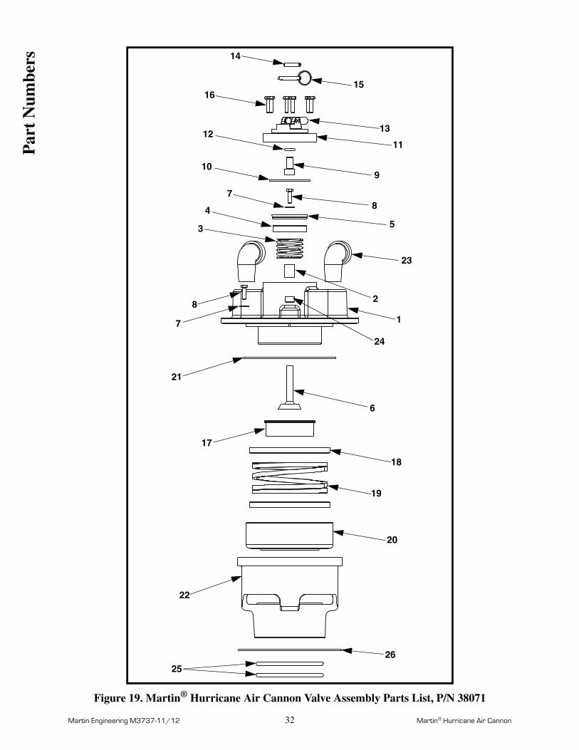
19 Martin® Hurricane Air Cannon Valve Assembly Parts List, P/N 38071. . . . 32
20 Martin® Multi Valve Air Cannon System Parts List, P/N 38625 . . . . . . . . . 34
21 Air Cannon Warning Label, P/N 33439 . . . . . . . . . . . . . . . . . . . . . . . . . . . . 36
22 Martin® Serial/Model Number Label, P/N 21313. . . . . . . . . . . . . . . . . . . . . 36
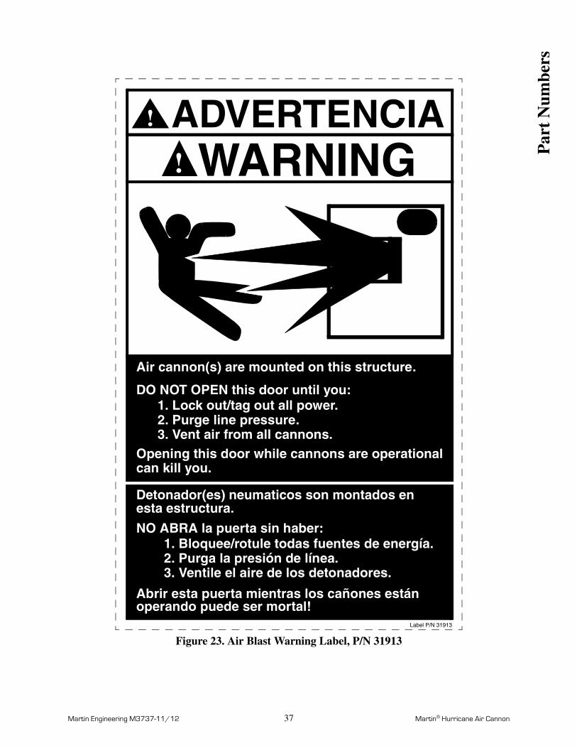
23 Air Blast Warning Label, P/N 31913. . . . . . . . . . . . . . . . . . . . . . . . . . . . . . . 37
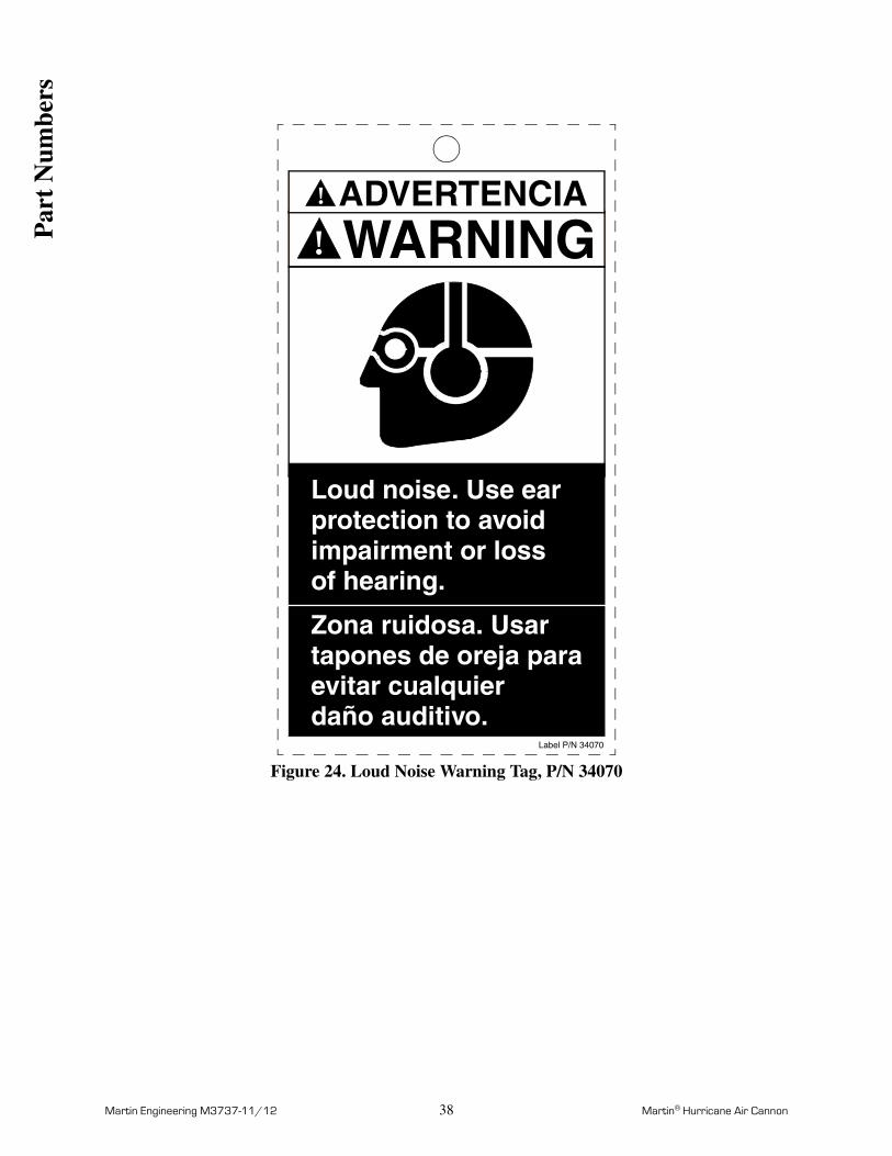
24 Loud Noise Warning Tag, P/N 34070 . . . . . . . . . . . . . . . . . . . . . . . . . . . . . . 38
Lis
t of
Fig
ures
Martin Engineering M3737-11/12 1 Martin® Hurricane Air Cannon
Introduction
General The Martin® Hurricane Air Cannon is a pneumatic bulk material-moving system that quickly releases compressed air into storage vessels, transfer chutes, gas ducts, and feed pipes to maintain material or gas flow.
This manual provides instructions for installing air cannons on steel structures only. For installations on other structures, call Martin Engineering or a representative.
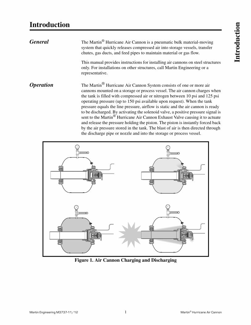
Operation The Martin® Hurricane Air Cannon System consists of one or more air cannons mounted on a storage or process vessel. The air cannon charges when the tank is filled with compressed air or nitrogen between 10 psi and 125 psi operating pressure (up to 150 psi available upon request). When the tank pressure equals the line pressure, airflow is static and the air cannon is ready to be discharged. By activating the solenoid valve, a positive pressure signal is sent to the Martin® Hurricane Air Cannon Exhaust Valve causing it to actuate and release the pressure holding the piston. The piston is instantly forced back by the air pressure stored in the tank. The blast of air is then directed through the discharge pipe or nozzle and into the storage or process vessel.
Figure 1. Air Cannon Charging and Discharging
Intr
oduc
tion
Martin Engineering M3737-11/12 2 Martin® Hurricane Air Cannon
Tank dataIMPORTANT
Never weld tank. Welding will melt paint and violate ASME coding.
The air cannon tank is manufactured to American Society of Mechanical Engineers (ASME) Code Rules, Section VIII, Division 1. It is National Board registered and is pressure vessel quality (PVQ). After the tank is welded, paint is applied inside the tank to prevent rust and corrosion. Never weld tank. Welding will melt paint and violate ASME coding.
Model and serial numbers
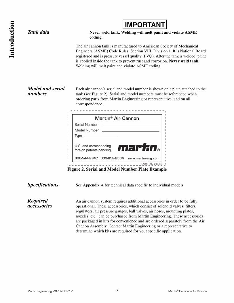
Each air cannon’s serial and model number is shown on a plate attached to the tank (see Figure 2). Serial and model numbers must be referenced when ordering parts from Martin Engineering or representative, and on all correspondence.
Figure 2. Serial and Model Number Plate Example
Specifications See Appendix A for technical data specific to individual models.
Required accessories
An air cannon system requires additional accessories in order to be fully operational. These accessories, which consist of solenoid valves, filters, regulators, air pressure gauges, ball valves, air hoses, mounting plates, nozzles, etc., can be purchased from Martin Engineering. These accessories are packaged in kits for convenience and are ordered separately from the Air Cannon Assembly. Contact Martin Engineering or a representative to determine which kits are required for your specific application.
Martin® Air CannonSerial Number
Model Number
Type
800-544-2947 309-852-2384 www.martin-eng.com
U.S. and corresponding foreign patents pending.
Label P/N 21313
Intr
oduc
tion
Martin Engineering M3737-11/12 3 Martin® Hurricane Air Cannon
References The following documents are referenced in this manual:
• American National Standards Institute (ANSI) z244.1-1982, American National Standard for Personnel Protection - Lockout/Tagout of Energy Sources - Minimum Safety Requirements, American National Standards Institute, Inc., 1430 Broadway, New York, NY 10018.
• Federal Register, Volume 54, Number 169, Part IV, 29 CFR Part 1910, Control of Hazardous Energy Source (Lockout/Tagout); Final Rule, Department of Labor, Occupational Safety and Health Administration (OSHA), 32nd Floor, Room 3244, 230 South Dearborn Street, Chicago, IL 60604.
• The National Electrical Code (NEC) Handbook, National Fire Protection Association, 1 Batterymarch Park, P.O. Box 9101, Quincy MA 02269-9101.
• ICS 1-1988, General Standards for Industrial Control and Systems, and 250-1985, Enclosures for Electrical Equipment (1000 Volts Maximum), National Electrical Manufacturers Association (NEMA), 2101 L Street N.W., Washington, D.C. 20037.
• Section VIII, Rules for Construction of Pressure Vessels, Division 1, American Society of Mechanical Engineers, United Engineering Center, 345 East 47th Street, New York, NY 10017.
Safety All safety rules defined in the above documents, and all owner/employer safety rules, must be strictly followed when installing and servicing this equipment.
Materials required Materials other than standard hand tools that are required to complete tasks are listed where applicable.
Intr
oduc
tion
Martin Engineering M3737-11/12 4 Martin® Hurricane Air Cannon
Before Installing Air Cannon
IMPORTANTThe delivery service is responsible for damage occurring in transit. Martin Engineering CANNOT enter claims for damages. Contact your transportation agent for more information.
1. Inspect shipping container for damage. Report damage to delivery service immediately and fill out delivery service’s claim form. Keep any damaged goods subject to examination.
2. Remove air cannon assembly from shipping container. A pressure relief valve, safety restraining cable, and warning labels will be included in this container.
3. If you purchased accessories from Martin Engineering, they will be packaged separately. Remove this equipment from its shipping container.
4. Take inventory of the equipment received. If anything is missing, contact Martin Engineering or representative.
WARNING!
Before installing air cannon, lock out/tag out any equipment that is loading or unloading material from the storage vessel.
5. Turn off and lock out/tag out energy source to accessory equipment according to ANSI standards (see “References”).
WARNING!
If equipment will be installed in an enclosed area, test gas level or dust content before using a cutting torch or welding. Using a cutting torch or welding in an area with gas or dust may cause an explosion.
6. If using a cutting torch or welding, test atmosphere for gas level or dust content.
CAUTION!
When blasting into closed storage vessel, exhaust vents must be considered to prevent internal vessel air pressure from increasing to point where it may damage vessel.
7. When blasting into a closed storage vessel, exhaust vents must be considered to prevent internal vessel air pressure from increasing to the point where it may damage the vessel. See Appendix A to determine the volume of air that will be introduced into the vessel with each air cannon blast. Observe local and state codes, which may specify internal pressure limits for your vessel.
Bef
ore
Inst
alla
tion
Martin Engineering M3737-11/12 5 Martin® Hurricane Air Cannon
IMPORTANTAir cannon force output can vary depending on inlet pressure, discharge opening size, structure size, material in structure, and other factors. To determine maximum force output values for your application, call Martin Engineering.
8. If you need to know air cannon maximum force output for your application, call Martin Engineering.
Bef
ore
Inst
alla
tion
Martin Engineering M3737-11/12 6 Martin® Hurricane Air Cannon
Installing Air Cannon
IMPORTANTRead entire section before beginning work.
To install air cannon, follow the procedures in this section corresponding to the following steps:
1. Install mounting plate.
2. Connect air cannon to mounting plate.
3. Install restraining cable.
4. Connect air supply to air cannon. See “electrical solenoid valves” as applicable.
A variety of mount plate and nozzle designs are available from Martin Engineering. This section will describe the installation of the most commonly used mount plates and nozzles. The correct mount plate or nozzle must be used for the given application. If you are not sure which mount plate or nozzle to use for your application, contact Martin Engineering or representative.
NOTENOTICE OF LIMITED LIABILITY: Due to possible presence of latent structural defects in the apparatus of the purchaser, Martin Engineering shall not be responsible for consequential damage to the purchaser’s equipment and/or apparatus resulting from the application of a Martin® Product. Martin Engineering shall not be liable for improper installation by the purchaser or other circumstances beyond the control of Martin Engineering. Liability is disclaimed for the structural soundness of apparatus or equipment not supplied by Martin Engineering. Liability shall be strictly limited to the replacement of the purchased product or refund of the purchase price. To secure the integrity of the installation, specify supervision by qualified personnel from Martin Engineering.
Installing mounting plate
Materials required: Mounting plate or seal plate and support structure.
Material and field welds: If mild steel to mild steel use a 7018 or equivalent rod. If stainless steel to stainless steel, use 308 or equivalent welding rod. If stainless steel to mild steel, use 309 or equivalent welding rod.
NOTEIf you are unsure where to locate air cannon(s) on your storage vessel, contact Martin Engineering or your representative.
1. Mark location for each air cannon on storage vessel.
2. A standard carbon steel mount plate or nozzle can be used for internal vessel temperatures of less than 500°F.
Ins
talla
tion
Martin Engineering M3737-11/12 7 Martin® Hurricane Air Cannon
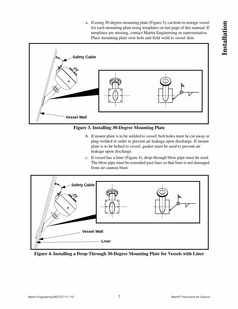
a. If using 30-degree mounting plate (Figure 3), cut hole in storage vessel for each mounting plate using templates on last page of this manual. If templates are missing, contact Martin Engineering or representative. Place mounting plate over hole and field weld to vessel skin.
Figure 3. Installing 30-Degree Mounting Plate
b. If mount plate is to be welded to vessel, bolt holes must be cut away or plug-welded in order to prevent air leakage upon discharge. If mount plate is to be bolted to vessel, gasket must be used to prevent air leakage upon discharge.
c. If vessel has a liner (Figure 4), drop-through blow-pipe must be used. The blow pipe must be extended past liner so that liner is not damaged from air cannon blast.
Figure 4. Installing a Drop-Through 30-Degree Mounting Plate for Vessels with Liner
Safety Cable
Vessel Wall
Safety Cable
Vessel Wall
Liner
Inst
alla
tion
Martin Engineering M3737-11/12 8 Martin® Hurricane Air Cannon
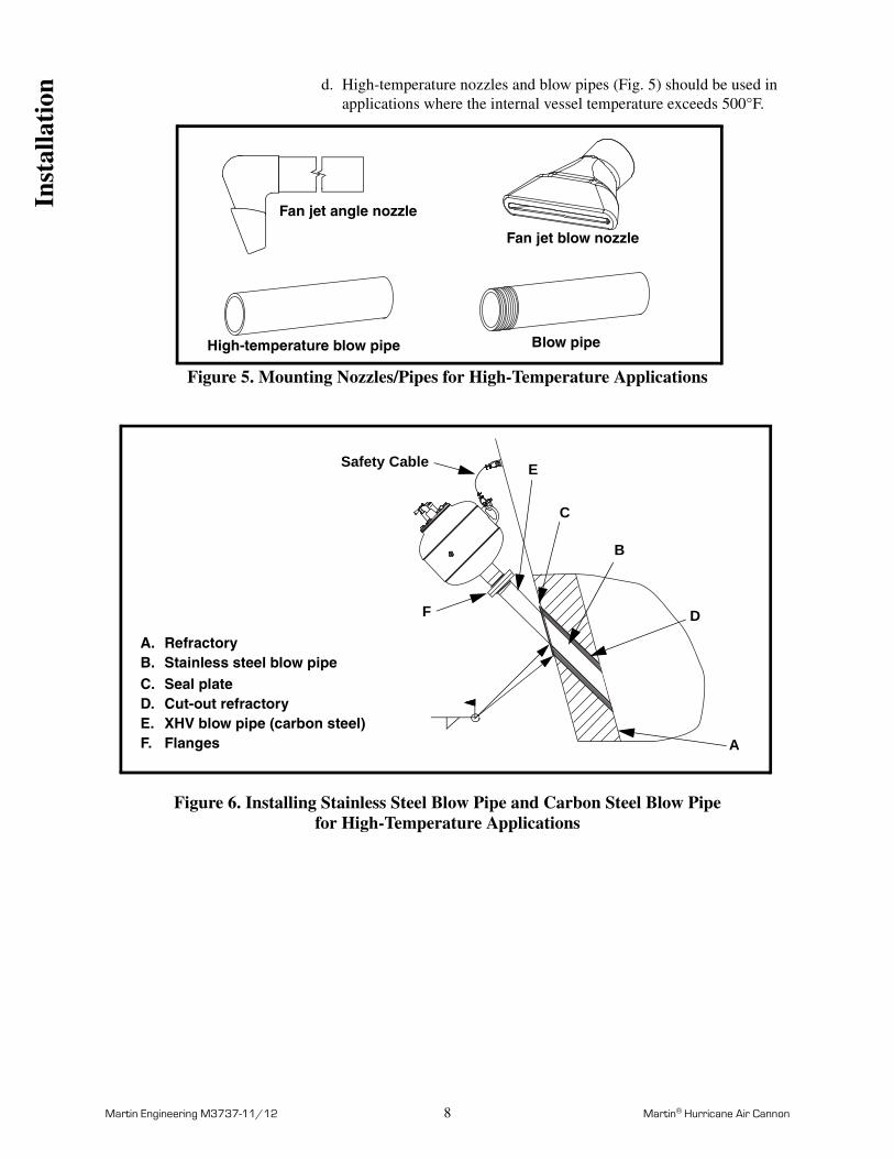
d. High-temperature nozzles and blow pipes (Fig. 5) should be used in applications where the internal vessel temperature exceeds 500°F.
Figure 5. Mounting Nozzles/Pipes for High-Temperature Applications
Figure 6. Installing Stainless Steel Blow Pipe and Carbon Steel Blow Pipe for High-Temperature Applications
Fan jet blow nozzle
Fan jet angle nozzle
High-temperature blow pipe Blow pipe
A.B.C.D.E.F.
RefractoryStainless steel blow pipeSeal plateCut-out refractoryXHV blow pipe (carbon steel)Flanges
D
A
C
B
E
F
Safety Cable
Inst
alla
tion
Martin Engineering M3737-11/12 9 Martin® Hurricane Air Cannon
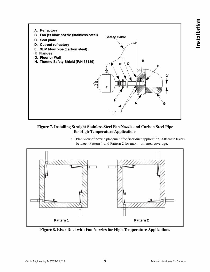
Figure 7. Installing Straight Stainless Steel Fan Nozzle and Carbon Steel Pipefor High-Temperature Applications
3. Plan view of nozzle placement for riser duct application. Alternate levels between Pattern 1 and Pattern 2 for maximum area coverage.
Figure 8. Riser Duct with Fan Nozzles for High-Temperature Applications
A.B.C.D.E.
RefractoryFan jet blow nozzle (stainless steel)Seal plateCut-out refractoryXHV blow pipe (carbon steel)
B
2”
EF. Flanges
F CD
A G
G. Floor or Wall
Safety Cable
F
H
H. Thermo Safety Shield (P/N 38189)
Pattern 1 Pattern 2
Inst
alla
tion
Martin Engineering M3737-11/12 10 Martin® Hurricane Air Cannon
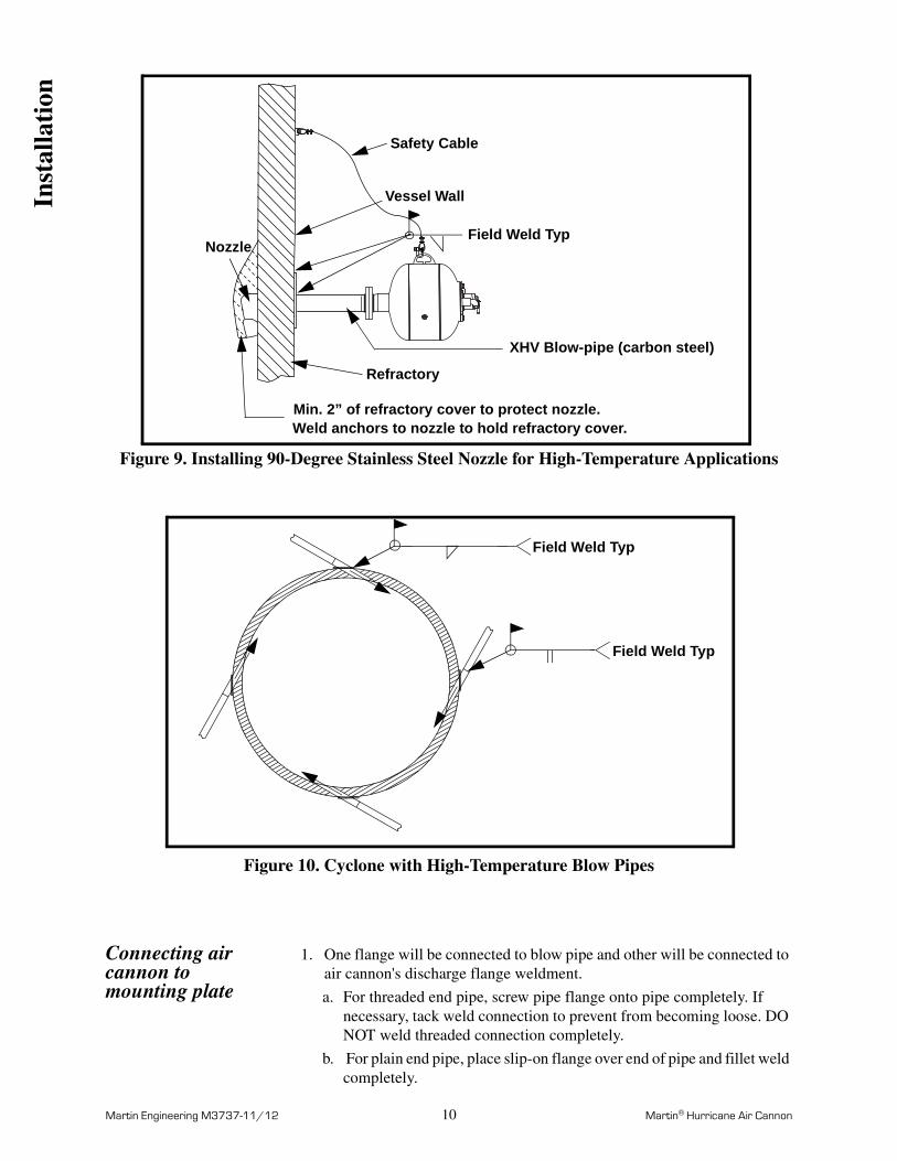
Figure 9. Installing 90-Degree Stainless Steel Nozzle for High-Temperature Applications
Figure 10. Cyclone with High-Temperature Blow Pipes
Connecting air cannon to mounting plate
1. One flange will be connected to blow pipe and other will be connected to air cannon's discharge flange weldment.
a. For threaded end pipe, screw pipe flange onto pipe completely. If necessary, tack weld connection to prevent from becoming loose. DO NOT weld threaded connection completely.
b. For plain end pipe, place slip-on flange over end of pipe and fillet weld completely.
Vessel Wall
Refractory
Min. 2” of refractory cover to protect nozzle.Weld anchors to nozzle to hold refractory cover.
NozzleField Weld Typ
XHV Blow-pipe (carbon steel)
Safety Cable
Field Weld Typ
Field Weld Typ
Inst
alla
tion
Martin Engineering M3737-11/12 11 Martin® Hurricane Air Cannon
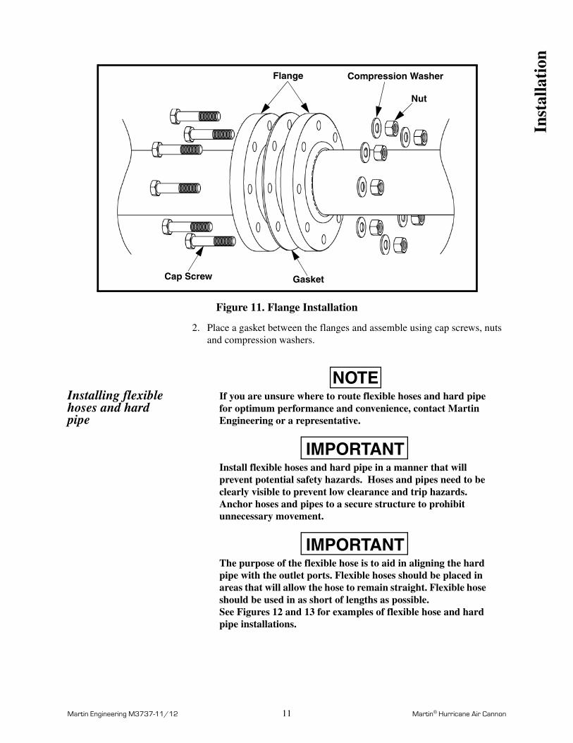
Figure 11. Flange Installation
2. Place a gasket between the flanges and assemble using cap screws, nuts and compression washers.
Installing flexible hoses and hard pipe
NOTEIf you are unsure where to route flexible hoses and hard pipe for optimum performance and convenience, contact Martin Engineering or a representative.
IMPORTANTInstall flexible hoses and hard pipe in a manner that will prevent potential safety hazards. Hoses and pipes need to be clearly visible to prevent low clearance and trip hazards. Anchor hoses and pipes to a secure structure to prohibit unnecessary movement.
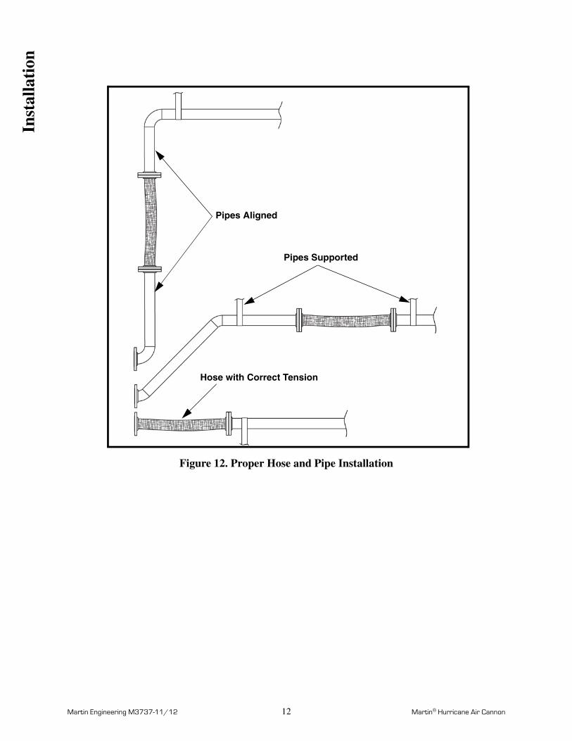
IMPORTANTThe purpose of the flexible hose is to aid in aligning the hard pipe with the outlet ports. Flexible hoses should be placed in areas that will allow the hose to remain straight. Flexible hose should be used in as short of lengths as possible. See Figures 12 and 13 for examples of flexible hose and hard pipe installations.
Nut
Compression WasherFlange
Cap Screw Gasket
Inst
alla
tion
Martin Engineering M3737-11/12 12 Martin® Hurricane Air Cannon
Figure 12. Proper Hose and Pipe Installation
Pipes Aligned
Pipes Supported
Hose with Correct Tension
Inst
alla
tion
Martin Engineering M3737-11/12 13 Martin® Hurricane Air Cannon
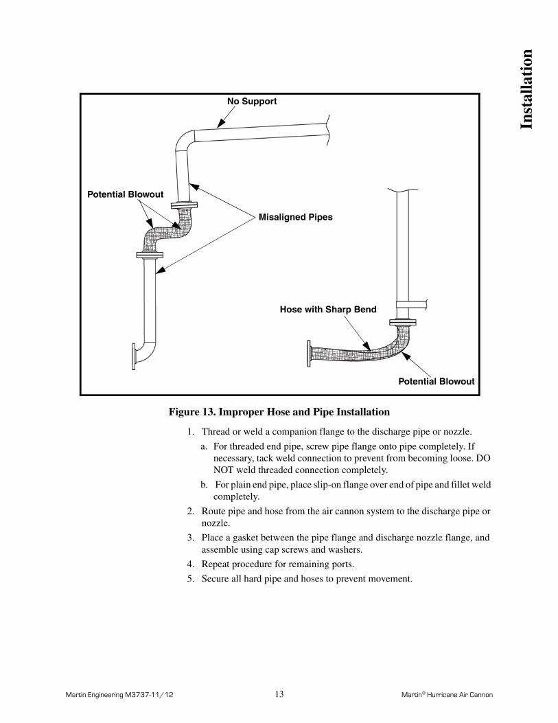
Figure 13. Improper Hose and Pipe Installation
1. Thread or weld a companion flange to the discharge pipe or nozzle.
a. For threaded end pipe, screw pipe flange onto pipe completely. If necessary, tack weld connection to prevent from becoming loose. DO NOT weld threaded connection completely.
b. For plain end pipe, place slip-on flange over end of pipe and fillet weld completely.
2. Route pipe and hose from the air cannon system to the discharge pipe or nozzle.
3. Place a gasket between the pipe flange and discharge nozzle flange, and assemble using cap screws and washers.
4. Repeat procedure for remaining ports.
5. Secure all hard pipe and hoses to prevent movement.
No Support
Misaligned Pipes
Hose with Sharp Bend
Potential Blowout
Potential Blowout
Inst
alla
tion
Martin Engineering M3737-11/12 14 Martin® Hurricane Air Cannon
Installing restraining cable
WARNING!
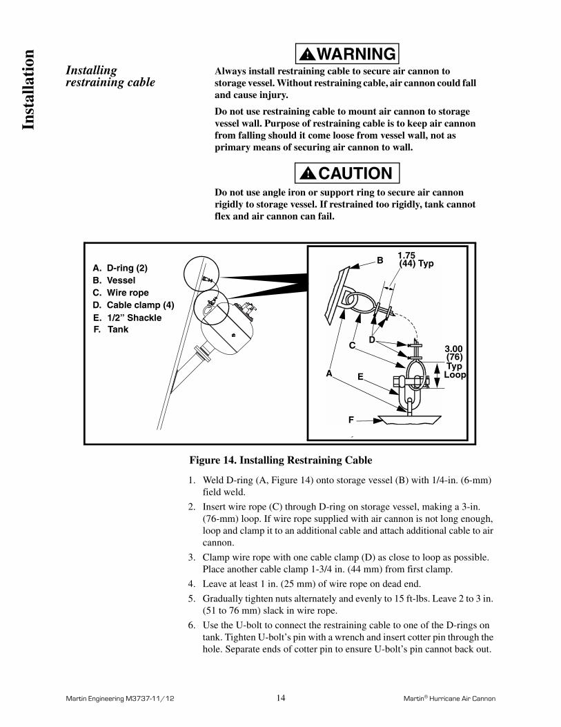
Always install restraining cable to secure air cannon to storage vessel. Without restraining cable, air cannon could fall and cause injury.
Do not use restraining cable to mount air cannon to storage vessel wall. Purpose of restraining cable is to keep air cannon from falling should it come loose from vessel wall, not as primary means of securing air cannon to wall.
CAUTION!
Do not use angle iron or support ring to secure air cannon rigidly to storage vessel. If restrained too rigidly, tank cannot flex and air cannon can fail.
Figure 14. Installing Restraining Cable
1. Weld D-ring (A, Figure 14) onto storage vessel (B) with 1/4-in. (6-mm) field weld.
2. Insert wire rope (C) through D-ring on storage vessel, making a 3-in. (76-mm) loop. If wire rope supplied with air cannon is not long enough, loop and clamp it to an additional cable and attach additional cable to air cannon.
3. Clamp wire rope with one cable clamp (D) as close to loop as possible. Place another cable clamp 1-3/4 in. (44 mm) from first clamp.
4. Leave at least 1 in. (25 mm) of wire rope on dead end.
5. Gradually tighten nuts alternately and evenly to 15 ft-lbs. Leave 2 to 3 in. (51 to 76 mm) slack in wire rope.
6. Use the U-bolt to connect the restraining cable to one of the D-rings on tank. Tighten U-bolt’s pin with a wrench and insert cotter pin through the hole. Separate ends of cotter pin to ensure U-bolt’s pin cannot back out.
A.B.C.D.
D-ring (2)VesselWire ropeCable clamp (4)
B
A
CD
E
E. 1/2” ShackleF. Tank
F
1.75(44) Typ
3.00(76) TypLoop
Inst
alla
tion
Martin Engineering M3737-11/12 15 Martin® Hurricane Air Cannon
Mount Martin® Multi Valve Air Cannon System
NOTEIf you are unsure where to locate the air cannon system in relation to your storage vessel, contact Martin Engineering or a representative.
WARNING!
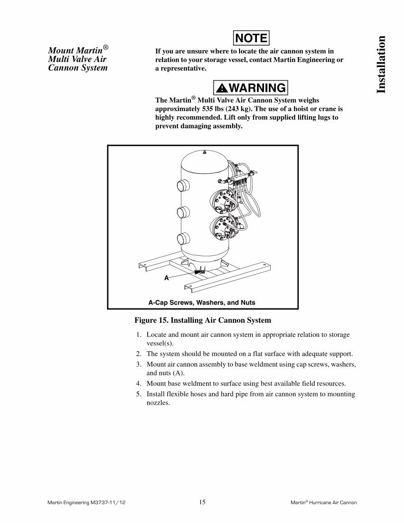
The Martin® Multi Valve Air Cannon System weighs approximately 535 lbs (243 kg). The use of a hoist or crane is highly recommended. Lift only from supplied lifting lugs to prevent damaging assembly.
Figure 15. Installing Air Cannon System
1. Locate and mount air cannon system in appropriate relation to storage vessel(s).
2. The system should be mounted on a flat surface with adequate support.
3. Mount air cannon assembly to base weldment using cap screws, washers, and nuts (A).
4. Mount base weldment to surface using best available field resources.
5. Install flexible hoses and hard pipe from air cannon system to mounting nozzles.
A
A-Cap Screws, Washers, and Nuts
Inst
alla
tion
Martin Engineering M3737-11/12 16 Martin® Hurricane Air Cannon
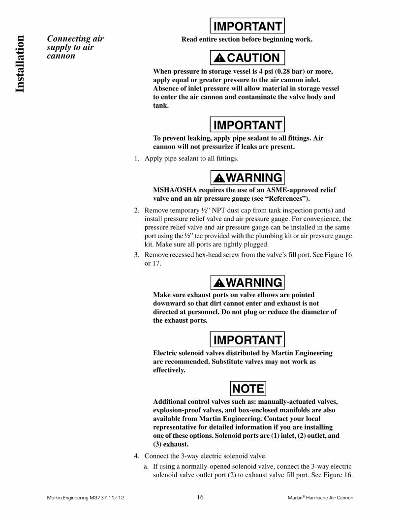
Connecting air supply to air cannon
IMPORTANTRead entire section before beginning work.
CAUTION!
When pressure in storage vessel is 4 psi (0.28 bar) or more, apply equal or greater pressure to the air cannon inlet. Absence of inlet pressure will allow material in storage vessel to enter the air cannon and contaminate the valve body and tank.
IMPORTANTTo prevent leaking, apply pipe sealant to all fittings. Air cannon will not pressurize if leaks are present.
1. Apply pipe sealant to all fittings.
WARNING!
MSHA/OSHA requires the use of an ASME-approved relief valve and an air pressure gauge (see “References”).
2. Remove temporary ½” NPT dust cap from tank inspection port(s) and install pressure relief valve and air pressure gauge. For convenience, the pressure relief valve and air pressure gauge can be installed in the same port using the ½” tee provided with the plumbing kit or air pressure gauge kit. Make sure all ports are tightly plugged.
3. Remove recessed hex-head screw from the valve’s fill port. See Figure 16 or 17.
WARNING!
Make sure exhaust ports on valve elbows are pointed downward so that dirt cannot enter and exhaust is not directed at personnel. Do not plug or reduce the diameter of the exhaust ports.
IMPORTANTElectric solenoid valves distributed by Martin Engineering are recommended. Substitute valves may not work as effectively.
NOTEAdditional control valves such as: manually-actuated valves, explosion-proof valves, and box-enclosed manifolds are also available from Martin Engineering. Contact your local representative for detailed information if you are installing one of these options. Solenoid ports are (1) inlet, (2) outlet, and (3) exhaust.
4. Connect the 3-way electric solenoid valve.
a. If using a normally-opened solenoid valve, connect the 3-way electric solenoid valve outlet port (2) to exhaust valve fill port. See Figure 16.
Ins
talla
tion
Martin Engineering M3737-11/12 17 Martin® Hurricane Air Cannon
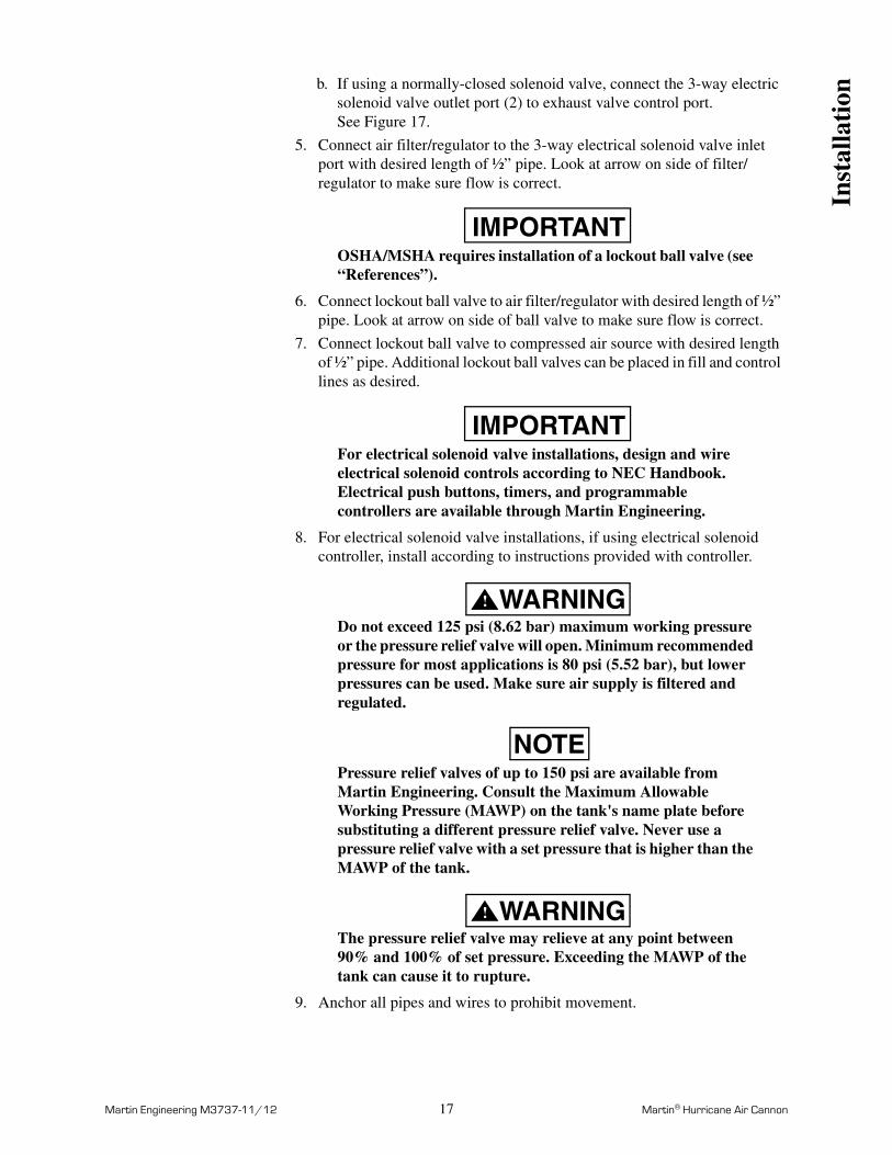
b. If using a normally-closed solenoid valve, connect the 3-way electric solenoid valve outlet port (2) to exhaust valve control port. See Figure 17.
5. Connect air filter/regulator to the 3-way electrical solenoid valve inlet port with desired length of ½” pipe. Look at arrow on side of filter/regulator to make sure flow is correct.
IMPORTANTOSHA/MSHA requires installation of a lockout ball valve (see “References”).
6. Connect lockout ball valve to air filter/regulator with desired length of ½” pipe. Look at arrow on side of ball valve to make sure flow is correct.
7. Connect lockout ball valve to compressed air source with desired length of ½” pipe. Additional lockout ball valves can be placed in fill and control lines as desired.
IMPORTANTFor electrical solenoid valve installations, design and wire electrical solenoid controls according to NEC Handbook. Electrical push buttons, timers, and programmable controllers are available through Martin Engineering.
8. For electrical solenoid valve installations, if using electrical solenoid controller, install according to instructions provided with controller.
WARNING!
Do not exceed 125 psi (8.62 bar) maximum working pressure or the pressure relief valve will open. Minimum recommended pressure for most applications is 80 psi (5.52 bar), but lower pressures can be used. Make sure air supply is filtered and regulated.
NOTEPressure relief valves of up to 150 psi are available from Martin Engineering. Consult the Maximum Allowable Working Pressure (MAWP) on the tank's name plate before substituting a different pressure relief valve. Never use a pressure relief valve with a set pressure that is higher than the MAWP of the tank.
WARNING!
The pressure relief valve may relieve at any point between 90% and 100% of set pressure. Exceeding the MAWP of the tank can cause it to rupture.
9. Anchor all pipes and wires to prohibit movement.
Inst
alla
tion
Martin Engineering M3737-11/12 18 Martin® Hurricane Air Cannon
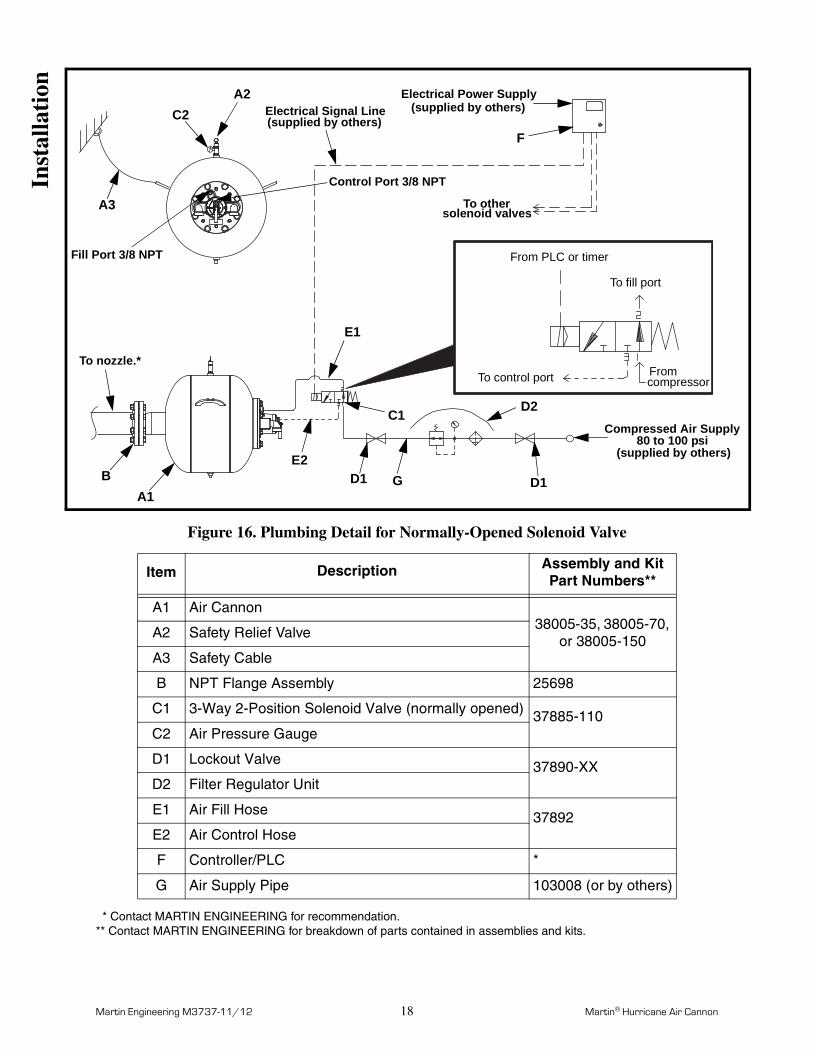
Figure 16. Plumbing Detail for Normally-Opened Solenoid Valve
* Contact MARTIN ENGINEERING for recommendation.** Contact MARTIN ENGINEERING for breakdown of parts contained in assemblies and kits.
Item Description Assembly and KitPart Numbers**
A1 Air Cannon38005-35, 38005-70,
or 38005-150A2 Safety Relief Valve
A3 Safety Cable
B NPT Flange Assembly 25698
C1 3-Way 2-Position Solenoid Valve (normally opened) 37885-110C2 Air Pressure Gauge
D1 Lockout Valve 37890-XXD2 Filter Regulator Unit
E1 Air Fill Hose 37892E2 Air Control Hose
F Controller/PLC *
G Air Supply Pipe 103008 (or by others)
A1B
A2
A3
Fill Port 3/8 NPT
Control Port 3/8 NPT
C2
C1
To nozzle.*
Electrical Signal Line(supplied by others)
D1
D2
D1
Compressed Air Supply80 to 100 psi
(supplied by others)
E1
E2
F
G
Electrical Power Supply(supplied by others)
To other
From PLC or timer
To control port
To fill port
compressorFrom
solenoid valves
Inst
alla
tion
Martin Engineering M3737-11/12 19 Martin® Hurricane Air Cannon
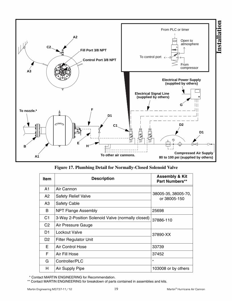
Figure 17. Plumbing Detail for Normally-Closed Solenoid Valve
* Contact MARTIN ENGINEERING for Recommendation.** Contact MARTIN ENGINEERING for breakdown of parts contained in assemblies and kits.
Item Description Assembly & Kit Part Numbers**
A1 Air Cannon38005-35, 38005-70,
or 38005-150A2 Safety Relief Valve
A3 Safety Cable
B NPT Flange Assembly 25698
C1 3-Way 2-Position Solenoid Valve (normally closed) 37886-110C2 Air Pressure Gauge
D1 Lockout Valve 37890-XXD2 Filter Regulator Unit
E Air Control Hose 33739
F Air Fill Hose 37452
G Controller/PLC *
H Air Supply Pipe 103008 or by others
From PLC or timer
To control port
Open to atmosphere
Fromcompressor
Fill Port 3/8 NPT
Control Port 3/8 NPT
To nozzle.*
Electrical Signal Line(supplied by others)
80 to 100 psi (supplied by others)
Electrical Power Supply(supplied by others)
To other air cannons. Compressed Air Supply
C2
A2
A3
D1
F
B
A1
EH
D2
D1
G
C1
Inst
alla
tion
Martin Engineering M3737-11/12 20 Martin® Hurricane Air Cannon
After Installing Air Cannon
IMPORTANTRead entire section before beginning work.
1. Thoroughly wipe storage vessel wall clean next to vessel door/port. Place Air Blast Warning Label, P/N 31913, on vessel wall visible to anyone opening door/port. If more than one door or port exists on storage vessel, request additional labels from Martin Engineering or representative. Attach Lockout Valve Warning Tag, P/N 35146, to lockout valve with cable tie (supplied).
2. Purge air lines.
IMPORTANTCharge each air cannon individually during initial start-up to avoid significant pressure loss.Relief valve is preset to open at 125 psi (8.62 bar).
WARNING!
Do not exceed 125 psi (8.62 bar) maximum working pressure or pressure relief valve will open. Minimum recommended pressure for most applications is 80 psi (5.52 bar) but lower pressures can be used. Make sure air supply is filtered and regulated.
NOTEPressure relief valves of up to 150 psi are available from Martin Engineering. Consult the Maximum Allowable Working Pressure (MAWP) on tank's name plate before substituting a different pressure relief valve. Never use a pressure relief valve with a set pressure that is higher than the MAWP of the tank.
WARNING!
Pressure relief valve may relieve at any point between 90% and 100% of set pressure. Exceeding MAWP can cause tank to rupture.
3. Supply 80 to 125 psi (5.52 to 8.62 bar) filtered and regulated air to system.
4. If air cannon does not charge, see “Troubleshooting.”
5. Check system for air leaks. If leaking, see “Troubleshooting.”
Aft
er I
nsta
llati
on
Martin Engineering M3737-11/12 21 Martin® Hurricane Air Cannon
NOTEWhen air cannon blasts, a small amount of air will release from solenoid valve and quick exhaust valve.
DANGER!
Do not open door/port or enter storage vessel when cannons are charged and operational. Flying debris from cannons’ blast can kill you.If air cannons are installed on open pit or on structure with no top, make sure area is clear before firing cannons. Flying debris from cannons’ blast can kill you.
WARNING!
Air cannons are loud when firing. Use ear protection to avoid impairment or loss of hearing.
6. Blast air cannon as follows: for air cannons with electrical solenoid valves and external electrical controls, activate electrical solenoid valve by external control (electrical push button, timer, etc.) or by pushing button on electrical solenoid valve. (If wired correctly, this should send signal to solenoid valve closing inlet to outlet and opening outlet to exhaust.)
7. Blast air cannon five times to ensure proper operation. Allow tank to fill after each blast.
8. If air cannon blasts properly, continue to operate air cannon as needed. If problems occur, see “Troubleshooting.”
9. Keep air cannon charged with air at all times so unit is always ready for use and so material cannot flow into air cannon.
Aft
er I
nsta
llati
on
Martin Engineering M3737-11/12 22 Martin® Hurricane Air Cannon
Maintenance
IMPORTANTRead entire section before beginning work.
WARNING!
Turn off and lock out/tag out air supply and energy source before blasting air cannon to prevent air cannon from refilling.
WARNING!
Do not open door/port or enter storage vessel before turning off compressed air source, locking out controls, purging line pressure, and venting air completely from tank.
Turn off and lock out/tag out energy source according to ANSI standards (see “References”).
Every month 1. Inspect all connections from air supply to tank for leaks and deterioration. If connections are leaking, seal all fittings with pipe sealant and tighten. Replace any deteriorating connections. Make sure hoses do not flex more than 1/4 inch (6 mm).
2. Make sure all pipes and wires are anchored to prohibit movement. Secure as needed.
3. Inspect valve assembly, electrical solenoid valve, lockout ball valve, and air filter/regulator for proper operation. If not operating correctly, replace.
4. Inspect air gauge for correct operation; make sure lens is clean and visible.
5. Inspect safety relief valve: pull ring to bleed off a small amount of compressed air and make sure diaphragm closes back to an air-tight seal.
6. Inspect safety cable (restraining cable); make sure clamp connections are secure and there is no excessive corrosion or frayed cable.
7. Wipe all warning labels clean. If labels are not readable, contact Martin Engineering or representative for replacements.
Mai
nten
ance
Martin Engineering M3737-11/12 23 Martin® Hurricane Air Cannon
Every year or 50,000 firings
1. Blast air cannon to remove air from tank, then pull ring on relief valve to make sure air stored in cannon has been released.
2. Perform monthly maintenance. See “Every month.”
3. After all air is released, remove drain plug. Allow all moisture to drain from tank.
4. After all moisture is removed, apply pipe sealant to drain plug. Install drain plug on tank.
CAUTION!
Do not weld tank. Paint in tank will melt and welding will violate ASME code. If tank is damaged or leaking, do not use air cannon until tank is replaced or repaired by Martin Engineering.
5. Inspect air cannon mounting area for rust and loose screws, welds, and bolts. Replace, tighten, or weld as necessary.
6. Inspect tank, valve body, piston, and discharge nozzle for damage. Replace or return to Martin Engineering for repair as necessary.
7. Inspect restraining cable for wear. Replace if worn.
8. On units with electrical controls, inspect wires and connections. Repair or replace wires to NEC Handbook standards as necessary.
Mai
nten
ance
Martin Engineering M3737-11/12 24 Martin® Hurricane Air Cannon
Valve Assembly Replacement
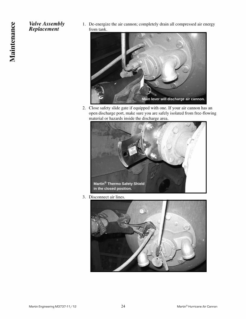
1. De-energize the air cannon; completely drain all compressed air energy from tank.
2. Close safety slide gate if equipped with one. If your air cannon has an open discharge port, make sure you are safely isolated from free-flowing material or hazards inside the discharge area.
3. Disconnect air lines.
Main lever will discharge air cannon.
Martin® Thermo Safety Shield in the closed position.
Mai
nten
ance
Martin Engineering M3737-11/12 25 Martin® Hurricane Air Cannon
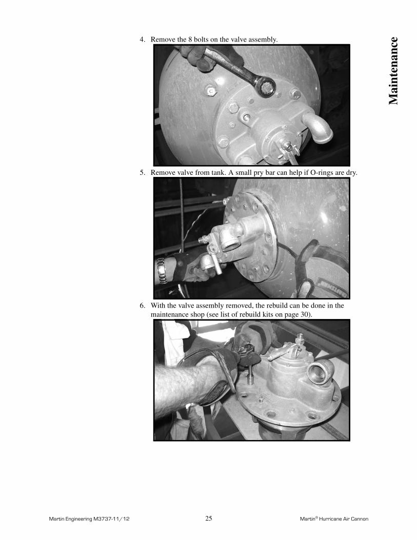
4. Remove the 8 bolts on the valve assembly.
5. Remove valve from tank. A small pry bar can help if O-rings are dry.
6. With the valve assembly removed, the rebuild can be done in the maintenance shop (see list of rebuild kits on page 30).
Mai
nten
ance
Martin Engineering M3737-11/12 26 Martin® Hurricane Air Cannon
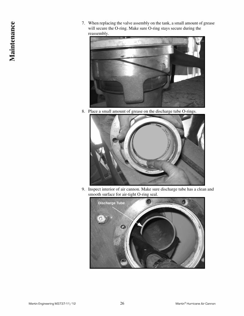
7. When replacing the valve assembly on the tank, a small amount of grease will secure the O-ring. Make sure O-ring stays secure during the reassembly.
8. Place a small amount of grease on the discharge tube O-rings.
9. Inspect interior of air cannon. Make sure discharge tube has a clean and smooth surface for air-tight O-ring seal.
Discharge Tube
Mai
nten
ance
Martin Engineering M3737-11/12 27 Martin® Hurricane Air Cannon
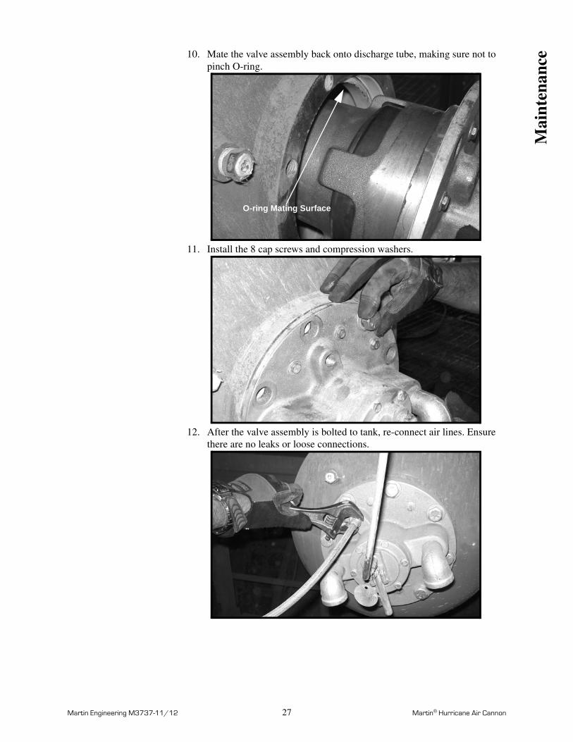
10. Mate the valve assembly back onto discharge tube, making sure not to pinch O-ring.
11. Install the 8 cap screws and compression washers.
12. After the valve assembly is bolted to tank, re-connect air lines. Ensure there are no leaks or loose connections.
O-ring Mating Surface
Mai
nten
ance
Martin Engineering M3737-11/12 28 Martin® Hurricane Air Cannon
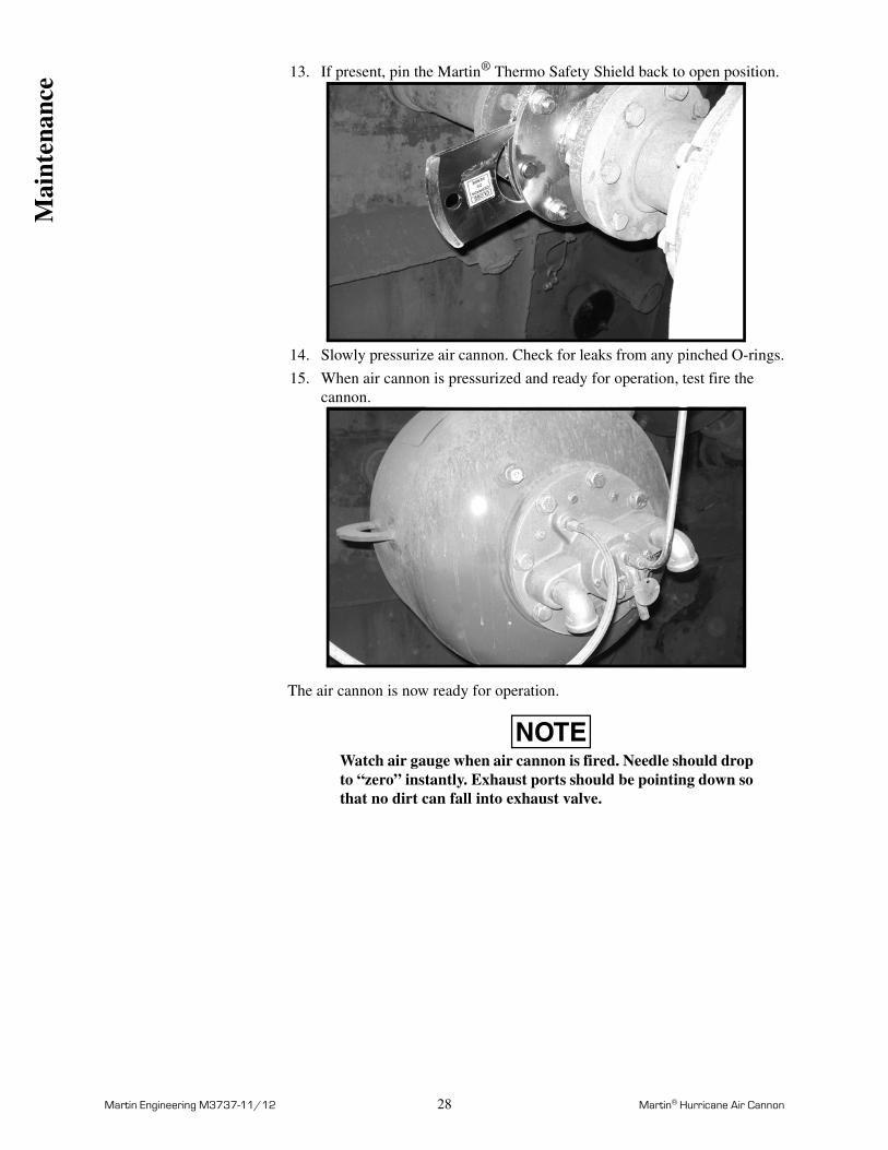
13. If present, pin the Martin® Thermo Safety Shield back to open position.
14. Slowly pressurize air cannon. Check for leaks from any pinched O-rings.
15. When air cannon is pressurized and ready for operation, test fire the cannon.
The air cannon is now ready for operation.
NOTEWatch air gauge when air cannon is fired. Needle should drop to “zero” instantly. Exhaust ports should be pointing down so that no dirt can fall into exhaust valve.
Mai
nten
ance
Martin Engineering M3737-11/12 29 Martin® Hurricane Air Cannon
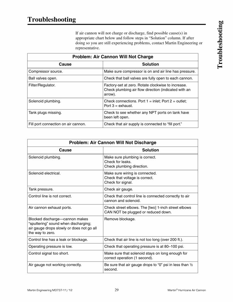
Troubleshooting
If air cannon will not charge or discharge, find possible cause(s) in appropriate chart below and follow steps in “Solution” column. If afterdoing so you are still experiencing problems, contact Martin Engineering or representative.
Problem: Air Cannon Will Not Charge
Cause Solution
Compressor source. Make sure compressor is on and air line has pressure.
Ball valves open. Check that ball valves are fully open to each cannon.
Filter/Regulator. Factory-set at zero. Rotate clockwise to increase.Check plumbing air flow direction (indicated with an arrow).
Solenoid plumbing. Check connections. Port 1 = inlet; Port 2 = outlet; Port 3 = exhaust.
Tank plugs missing. Check to see whether any NPT ports on tank have been left open.
Fill port connection on air cannon. Check that air supply is connected to “fill port.”
Problem: Air Cannon Will Not Discharge
Cause Solution
Solenoid plumbing. Make sure plumbing is correct. Check for leaks. Check plumbing direction.
Solenoid electrical. Make sure wiring is connected.Check that voltage is correct.Check for signal.
Tank pressure. Check air gauge.
Control line is not correct. Check that control line is connected correctly to air cannon and solenoid.
Air cannon exhaust ports. Check street elbows. The [two] 1-inch street elbows CAN NOT be plugged or reduced down.
Blocked discharge—cannon makes “sputtering” sound when discharging; air gauge drops slowly or does not go all the way to zero.
Remove blockage.
Control line has a leak or blockage. Check that air line is not too long (over 200 ft.).
Operating pressure is low. Check that operating pressure is at 80–100 psi.
Control signal too short. Make sure that solenoid stays on long enough for correct operation (1 second).
Air gauge not working correctly. Be sure that air gauge drops to “0” psi in less than ½ second.
Tro
uble
shoo
ting
Martin Engineering M3737-11/12 30 Martin® Hurricane Air Cannon
Part Numbers
This section provides product names and corresponding part numbers for Martin® Hurricane Air Cannons and related equipment. Please reference part numbers when ordering parts. Part numbers for accessory equipment not listed here are available from Martin Engineering or representative.
Air Cannons Martin® Hurricane Air Cannon Assembly:
Model 35 L: P/N 38005-35
Model 70 L: P/N 38005-70
Model 150 L: P/N 38005-150
Martin® Multi Valve Air Cannon System: P/N 38625
Air Cannon Repair Parts
Pressure Relief Valve: P/N 21680
Air Pressure Gauge: P/N 34842
Safety Cable Kit: P/N 32271
Martin® Hurricane Air Cannon Valve Assembly: P/N 38071
Martin® Hurricane Air Cannon Exhaust Valve Rebuild Kit: P/N 38137-4
Martin® Hurricane Air Cannon Main Piston Rebuild Kit: P/N 38426
Contact Martin Engineering for information on other repair parts.
Par
t N
umbe
rs
Martin Engineering M3737-11/12 31 Martin® Hurricane Air Cannon
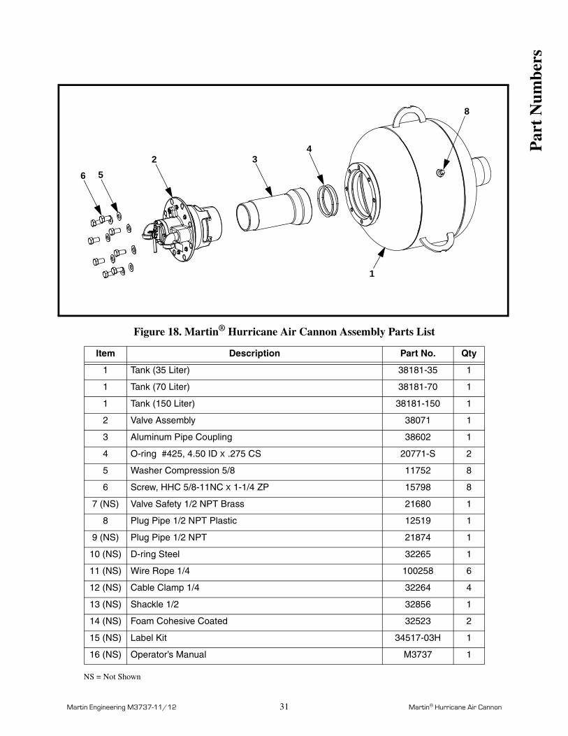
Figure 18. Martin® Hurricane Air Cannon Assembly Parts List
NS = Not Shown
Item Description Part No. Qty
1 Tank (35 Liter) 38181-35 1
1 Tank (70 Liter) 38181-70 1
1 Tank (150 Liter) 38181-150 1
2 Valve Assembly 38071 1
3 Aluminum Pipe Coupling 38602 1
4 O-ring #425, 4.50 ID X .275 CS 20771-S 2
5 Washer Compression 5/8 11752 8
6 Screw, HHC 5/8-11NC X 1-1/4 ZP 15798 8
7 (NS) Valve Safety 1/2 NPT Brass 21680 1
8 Plug Pipe 1/2 NPT Plastic 12519 1
9 (NS) Plug Pipe 1/2 NPT 21874 1
10 (NS) D-ring Steel 32265 1
11 (NS) Wire Rope 1/4 100258 6
12 (NS) Cable Clamp 1/4 32264 4
13 (NS) Shackle 1/2 32856 1
14 (NS) Foam Cohesive Coated 32523 2
15 (NS) Label Kit 34517-03H 1
16 (NS) Operator’s Manual M3737 1
1
8
43
6 52
Par
t N
umbe
rs
Martin Engineering M3737-11/12 32 Martin® Hurricane Air Cannon
Figure 19. Martin® Hurricane Air Cannon Valve Assembly Parts List, P/N 38071
15
14
13
16
1112
9
8
5
7
23
3
2
24
1
8
7
21
6
17
18
19
20
22
26
25
4
10
Par
t N
umbe
rs
Martin Engineering M3737-11/12 33 Martin® Hurricane Air Cannon
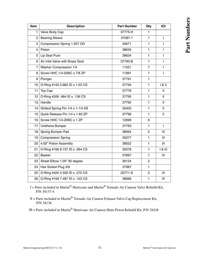
I = Parts included in Martin® Hurricane and Martin® Tornado Air Cannon Valve Rebuild Kit, P/N 38137-4
II = Parts included in Martin® Tornado Air Cannon Exhaust Valve Cap Replacement Kit, P/N 38136
III = Parts included in Martin® Hurricane Air Cannon Main Piston Rebuild Kit, P/N 38426
Item Description Part Number Qty Kit
1 Valve Body Cap 37775-H 1
2 Bearing Sleeve 37287-1 1 I
3 Compression Spring 1.937 OD 34671 1 I
4 Piston 38635 1 I
5 Lip Seal Puck 38634 1 I
6 Air Inlet Valve with Brass Seat 37790-B 1 I
7 Washer Compression 1/4 11521 7 I
8 Screw HHC 1/4-20NC x 7/8 ZP 11891 7 I
9 Plunger 37791 1
10 O-Ring #150 2.862 ID x 1.03 CS 37794 1 I & II
11 Top Cap 37776 1 II
12 O-Ring #206 .484 ID x .139 CS 37795 1 II
13 Handle 37792 1 II
14 Slotted Spring Pin 1/4 x 1-1/4 SS 32403 1 II
15 Quick Release Pin 1/4 x 1.63 ZP 37796 1 II
16 Screw HHC 1/4-20NC x 1 ZP 12699 6
17 Urethane Bumper 37793 1 I
18 Spring Bumper Pad 38064 2 III
19 Compression Spring 35077 1 III
20 4.00” Piston Assembly 38022 1 III
21 O-Ring #166 6.737 ID x .094 CS 35078 1 I & III
22 Basket 37897 1 III
23 Street Elbow 1.00” 90 degree 36124 2
24 Hex Socket Plug 3/8 37987 1
25 O-Ring #425 4.500 ID x .275 CS 20771-S 2 III
26 O-Ring #169 7.487 ID x .103 CS 38066 1 III
Par
t N
umbe
rs

Martin Engineering M3737-11/12 34 Martin® Hurricane Air Cannon
Figure 20. Martin® Multi Valve Air Cannon System Parts List, P/N 38625
2
9
7
83456
1
20
13
14 15 16 17 1822
1921
11
10
Par
t N
umbe
rs
Martin Engineering M3737-11/12 35 Martin® Hurricane Air Cannon
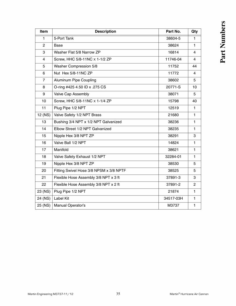
Item Description Part No. Qty
1 5-Port Tank 38604-5 1
2 Base 38624 1
3 Washer Flat 5/8 Narrow ZP 16814 4
4 Screw, HHC 5/8-11NC X 1-1/2 ZP 11746-04 4
5 Washer Compression 5/8 11752 44
6 Nut Hex 5/8-11NC ZP 11772 4
7 Aluminum Pipe Coupling 38602 5
8 O-ring #425 4.50 ID x .275 CS 20771-S 10
9 Valve Cap Assembly 38071 5
10 Screw, HHC 5/8-11NC X 1-1/4 ZP 15798 40
11 Plug Pipe 1/2 NPT 12519 1
12 (NS) Valve Safety 1/2 NPT Brass 21680 1
13 Bushing 3/4 NPT x 1/2 NPT Galvanized 38236 1
14 Elbow Street 1/2 NPT Galvanized 38235 1
15 Nipple Hex 3/8 NPT ZP 38291 3
16 Valve Ball 1/2 NPT 14824 1
17 Manifold 38621 1
18 Valve Safety Exhaust 1/2 NPT 32284-01 1
19 Nipple Hex 3/8 NPT ZP 38530 5
20 Fitting Swivel Hose 3/8 NPSM x 3/8 NPTF 38525 5
21 Flexible Hose Assembly 3/8 NPT x 3 ft 37891-3 3
22 Flexible Hose Assembly 3/8 NPT x 2 ft 37891-2 2
23 (NS) Plug Pipe 1/2 NPT 21874 1
24 (NS) Label Kit 34517-03H 1
25 (NS) Manual Operator’s M3737 1
Par
t N
umbe
rs
Martin Engineering M3737-11/12 36 Martin® Hurricane Air Cannon
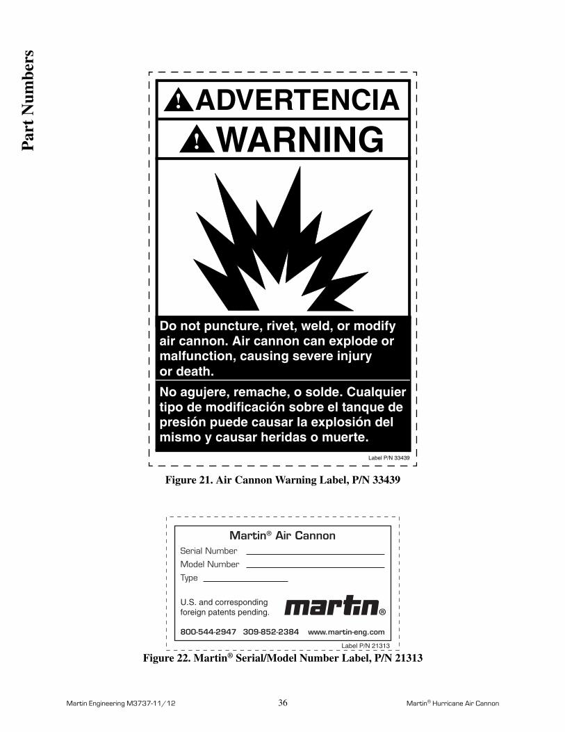
Figure 21. Air Cannon Warning Label, P/N 33439
Figure 22. Martin® Serial/Model Number Label, P/N 21313
WARNING!
Do not puncture, rivet, weld, or modifyair cannon. Air cannon can explode ormalfunction, causing severe injury
Label P/N 33439
mismo y causar heridas o muerte.presión puede causar la explosión del tipo de modificación sobre el tanque de No agujere, remache, o solde. Cualquier
ADVERTENCIA!
or death.
Martin® Air CannonSerial Number
Model Number
Type
800-544-2947 309-852-2384 www.martin-eng.com
U.S. and corresponding foreign patents pending.
Label P/N 21313
Par
t N
umbe
rs
Martin Engineering M3737-11/12 37 Martin® Hurricane Air Cannon
Figure 23. Air Blast Warning Label, P/N 31913
WARNING
Air cannon(s) are mounted on this structure.
Label P/N 31913
ADVERTENCIA!
!
DO NOT OPEN this door until you:1. Lock out/tag out all power.2. Purge line pressure.
Detonador(es) neumaticos son montados en
NO ABRA la puerta sin haber:1. Bloquee/rotule todas fuentes de energía.2. Purga la presión de línea.3. Ventile el aire de los detonadores.
Abrir esta puerta mientras los cañones estánoperando puede ser mortal!
3. Vent air from all cannons.Opening this door while cannons are operationalcan kill you.
esta estructura.
Par
t N
umbe
rs
Martin Engineering M3737-11/12 38 Martin® Hurricane Air Cannon
Figure 24. Loud Noise Warning Tag, P/N 34070
WARNING!
Loud noise. Use earprotection to avoidimpairment or lossof hearing.
Zona ruidosa. Usartapones de oreja paraevitar cualquierdaño auditivo.
ADVERTENCIA!
Label P/N 34070
Par
t N
umbe
rs

Martin Engineering M3737-11/12 A-1 Martin® Hurricane Air Cannon
App
endi
x A
Appendix AMartin® Hurricane Air Cannon
Specifications and Performance Data
Martin Engineering M3737-11/12 A-2 Martin® Hurricane Air Cannon
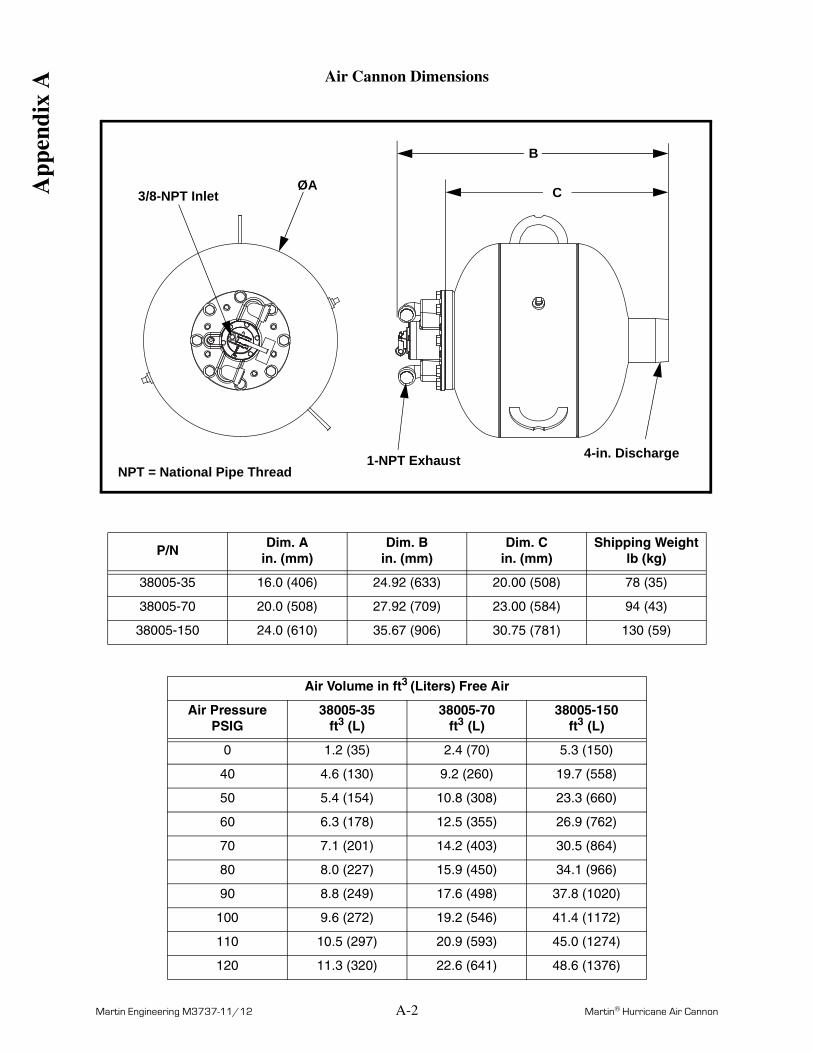
Air Cannon Dimensions
P/NDim. A
in. (mm)Dim. B
in. (mm)Dim. C
in. (mm)Shipping Weight
lb (kg)
38005-35 16.0 (406) 24.92 (633) 20.00 (508) 78 (35)
38005-70 20.0 (508) 27.92 (709) 23.00 (584) 94 (43)
38005-150 24.0 (610) 35.67 (906) 30.75 (781) 130 (59)
Air Volume in ft3 (Liters) Free Air
Air Pressure PSIG
38005-35ft3 (L)
38005-70ft3 (L)
38005-150ft3 (L)
0 1.2 (35) 2.4 (70) 5.3 (150)
40 4.6 (130) 9.2 (260) 19.7 (558)
50 5.4 (154) 10.8 (308) 23.3 (660)
60 6.3 (178) 12.5 (355) 26.9 (762)
70 7.1 (201) 14.2 (403) 30.5 (864)
80 8.0 (227) 15.9 (450) 34.1 (966)
90 8.8 (249) 17.6 (498) 37.8 (1020)
100 9.6 (272) 19.2 (546) 41.4 (1172)
110 10.5 (297) 20.9 (593) 45.0 (1274)
120 11.3 (320) 22.6 (641) 48.6 (1376)
3/8-NPT Inlet
1-NPT Exhaust 4-in. DischargeNPT = National Pipe Thread
ØA C
B
App
endi
x A
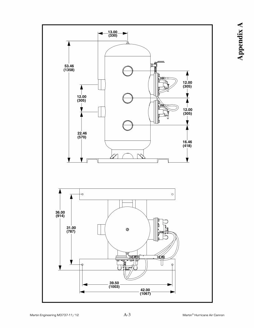
Martin Engineering M3737-11/12 A-3 Martin® Hurricane Air Cannon
39.50(1003)
42.00(1067)
36.00(914)
31.00(787)
12.00(305)
22.46(570)
53.46(1358)
16.46(418)
12.00(305)
12.00(305)
13.00(330)
App
endi
x A
Martin Engineering M3737-11/12 A-4 Martin® Hurricane Air Cannon
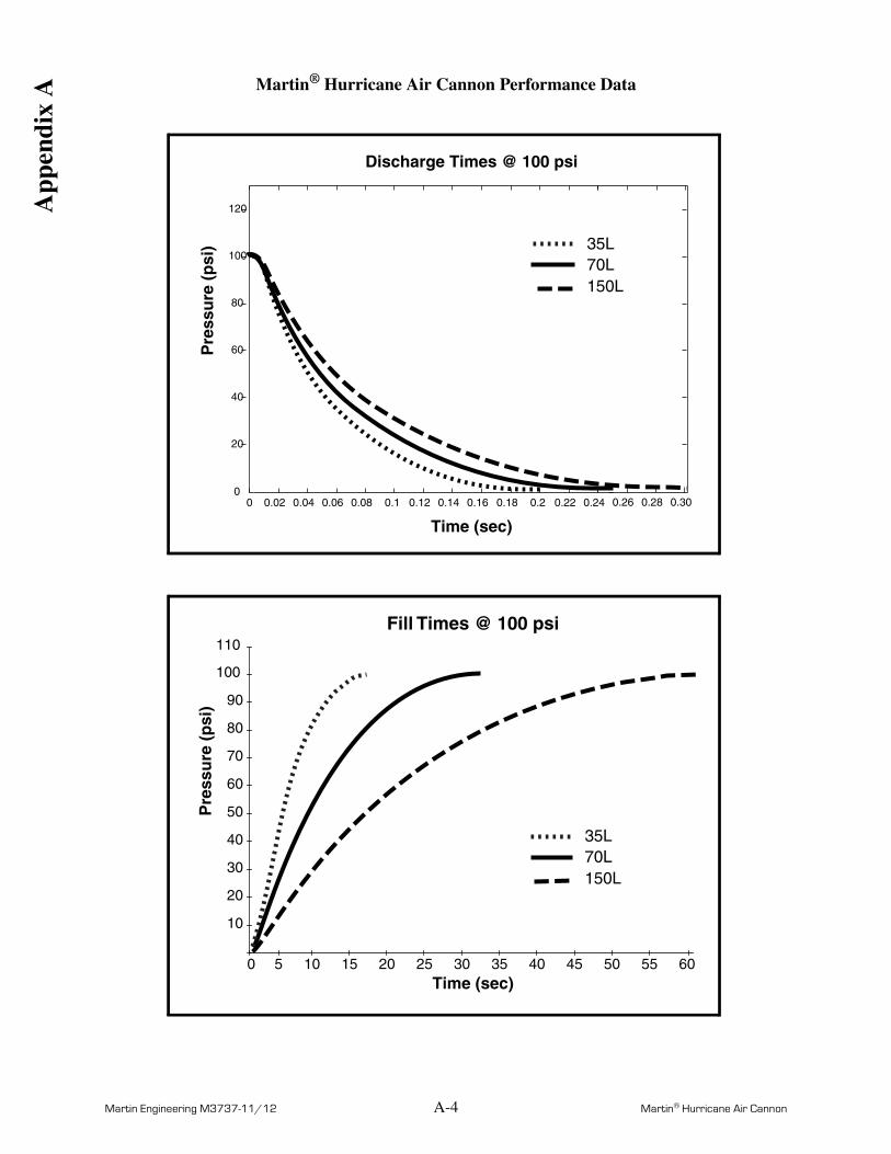
Martin® Hurricane Air Cannon Performance Data
Discharge Times @ 100 psi
0 0.02 0.04 0.06 0.08 0.1 0.12 0.14 0.16 0.18 0.2 0.22 0.240
20
40
60
80
100
120
Time (sec)
Pre
ssu
re (
psi
) 35L
150L 70L
0.26 0.28 0.30
Fill Times @ 100 psi
Time (sec)0 5 10 15 20 25 30 35 40 45 50 55 60
Pre
ssu
re (
psi
)
10
20
30
40
50
60
70
80
90
100
110
35L
150L 70L
App
endi
x A
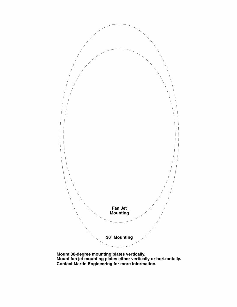
30° Mounting
Fan JetMounting
Mount 30-degree mounting plates vertically.Mount fan jet mounting plates either vertically or horizontally.Contact Martin Engineering for more information.


Any product, process, or technology described here may be the subject of intellectual property rights reserved by Martin Engineering Company. Trademarks or service marks designated with the ® symbol are registered with the U.S. Patent and Trademark Office and may be proprietary in one or more countries or regions. Other trademarks and service marks belonging to Martin Engineering Company in the United States and/or other countries or regions may be designated with the “TM” and “SM” symbols. Brands, trademarks, and names of other parties, who may or may not be affiliated with, connected to, or endorsed by Martin Engineering Company, are identified wherever possible. Additional information regarding Martin Engineering Company’s intellectual property can be obtained at www.martin-eng.com/trademarks.
Martin Engineering USAOne Martin PlaceNeponset, IL 61345-9766 USA800 544 2947 or 309 852 2384Fax 800 814 1553www.martin-eng.com
Form No. M3737-11/12 © Martin Engineering Company 2007, 2012