Embed Size (px)
Citation preview

Martin BatesElsevier 2008
Programming 8-bit PIC Microcontrollers in C

This presentation contains selected illustrations and program listings from the book ‘Programming 8-bit PIC Microcontrollers in C’ by Martin Bates
Part 1 Microcontroller Systems describes in detail the internal architecture and interfaces available in a typical PIC chip, and outlines the main
features of the MPLAB development system
Part 2 C Programming Essentialsprovides simple examples which introduce the basic
principles of C programming for microcontrollers using CCS C
Part 3 C Peripheral Interfacesprovides example programs for operating PIC chips with a full range of peripherals, using timers and interrupts

C PERIPHERAL INTERFACES
Part 3
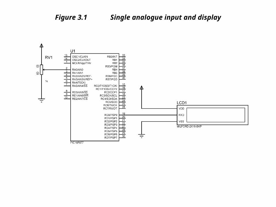
Figure 3.1 Single analogue input and display
Listing 3.1 Simple analogue input test
/* ANALIN.C MPB 5-1-07Read & display analogue input
***************************************************************************/ #include "16F877A.h"#device ADC=8 // 8-bit conversion #use delay(clock=4000000)#use rs232(baud=9600, xmit=PIN_D0, rcv=PIN_D1) // LCD output void main() //************************************************************{
int vin0; // Input variable
setup_adc(ADC_CLOCK_INTERNAL); // ADC clock setup_adc_ports(ALL_ANALOG); // Input combinationset_adc_channel(0); // Select RA0
for(;;) { delay_ms(500);
vin0 = read_adc(); // Get input bytevin0 = (vin0/32)+0x30; // Convert to ASCII
putc(254); putc(1); delay_ms(10); // Clear screenprintf("Input = "); putc(vin0); // Display input
} }

ANALOGUE INPUTS
ADC SETUP Initialise ADC setup_adc(ADC_CLOCK_INTERNAL);
ADC PINS SETUP Initialise ADC pins setup_adc_ports(RA0_ANALOG);
ADC CHANNEL SELECT Select ADC input set_adc_channel(0);
ADC READ Read analogue input inval = read_adc();
Table 3.1 CCS C Analogue Input Functions
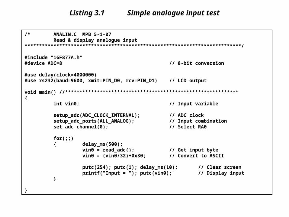
Table 3.2 CCS C Interrupt Functions
Label Operation Syntax Example
INTERRUPT CLEAR Clears peripheral interrupt clear_interrupt(int_timer0);
INTERRUPT DISABLE Disables peripheral interrupt disable_interrupts(int_timer0);
INTERRUPT ENABLE Enables peripheral interrupt enable_interrupts(int_timer0);
INTERRUPT ACTIVE Checks if interrupt flag set interrupt_active(int_timer0);
INTERRUPT EDGE Selects interrupt trigger edge ext_int_edge(H_TO_L);
INTERRUPT JUMP Jump to address of ISR jump_to_isr(isr_loc);

Tables 3.3 & 3.4 PIC 16F877 Interrupt Sources
INTERUPTLABEL
REGISTERCODE
INTERRUPTSOURCE
INT_EXT
0x0B10 External interrupt has been detected
INT_RB
0x0B08 Change on Port B has been detected
INT_RTCC
0x0B20 Timer 0 has overflowed (same as TIMER0
INT_TIMER0
0x0B20 Timer 0 has overflowed (same as RTCC)
INT_TIMER1
0x8C10 Timer 1 has overflowed
INT_CCP1
0x8C04 Timer 1 matches preset value?
INT_TIMER2
0x8C02 Timer 2 has overflowed
INT_CCP2
0x8D01 Timer 2 matches preset value?
INT_AD
0x8C40 Analogue to digital converter has finished
INT_SSP
0x8C08 Serial data has been received
INT_PSP
0x8C80 Data ready at parallel serial port
INT_EEPROM
0x8D10 Data EEPROM write completed

Figure 3.3 External interrupt test hardware
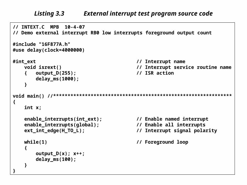
Listing 3.3 External interrupt test program source code
// INTEXT.C MPB 10-4-07// Demo external interrupt RB0 low interrupts foreground output count #include "16F877A.h"#use delay(clock=4000000) #int_ext // Interrupt name void isrext() // Interrupt service routine name { output_D(255); // ISR action delay_ms(1000); } void main() //**************************************************************{ int x; enable_interrupts(int_ext); // Enable named interrupt enable_interrupts(global); // Enable all interrupts ext_int_edge(H_TO_L); // Interrupt signal polarity while(1) // Foreground loop { output_D(x); x++; delay_ms(100); }}
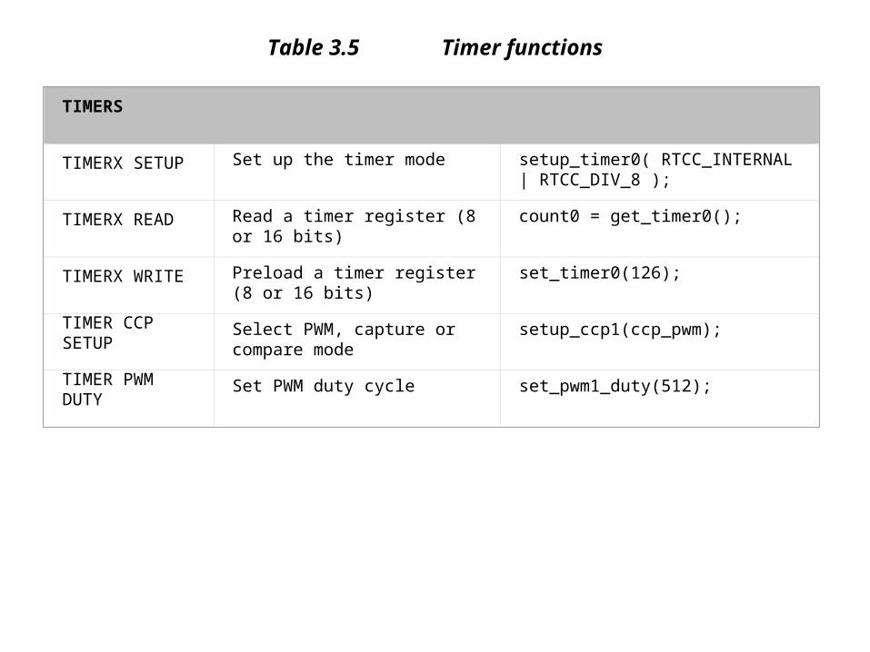
Table 3.5 Timer functions
TIMERS
TIMERX SETUP Set up the timer mode setup_timer0( RTCC_INTERNAL | RTCC_DIV_8 );
TIMERX READ Read a timer register (8 or 16 bits) count0 = get_timer0();
TIMERX WRITE Preload a timer register (8 or 16 bits)
set_timer0(126);
TIMER CCP SETUP
Select PWM, capture or compare mode
setup_ccp1(ccp_pwm);
TIMER PWM DUTY
Set PWM duty cycle set_pwm1_duty(512);
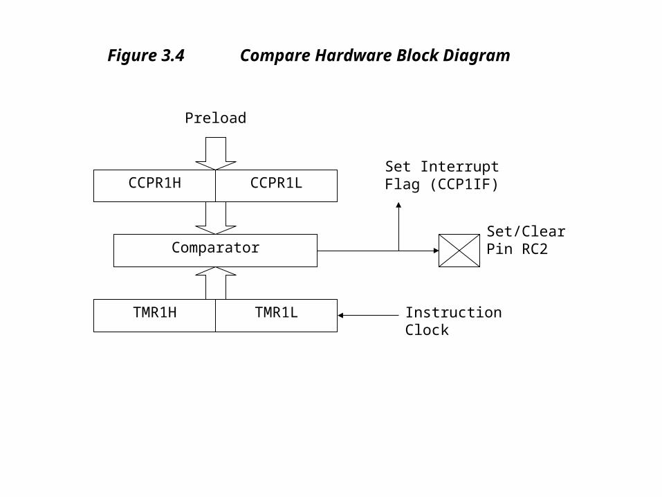
CCPR1H
Comparator
CCPR1L
TMR1H TMR1L
Set Interrupt Flag (CCP1IF)
Set/ClearPin RC2
Preload
InstructionClock
Figure 3.4 Compare Hardware Block Diagram

Listing 3.4 Pulse width modulation program source code
// PWM.C MPB 11-4-07// Demo PWM output #include "16F877A.h" void main(){ setup_ccp1(ccp_pwm); // Select timer module and mode set_pwm1_duty(500); // Set on time setup_timer_2(T2_DIV_BY_16,248,1); // Clock rate &
// output period while(1){}}
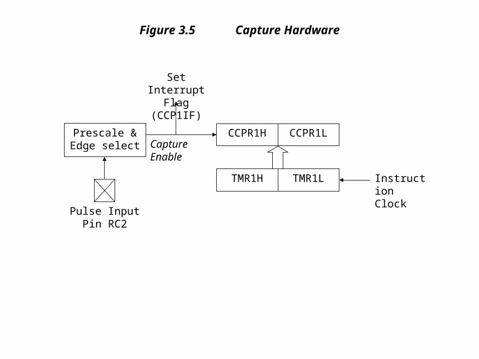
CCPR1H CCPR1L
TMR1H TMR1L
Set Interrupt Flag (CCP1IF)
Pulse InputPin RC2
InstructionClock
Prescale &Edge select Capture
Enable
Figure 3.5 Capture Hardware
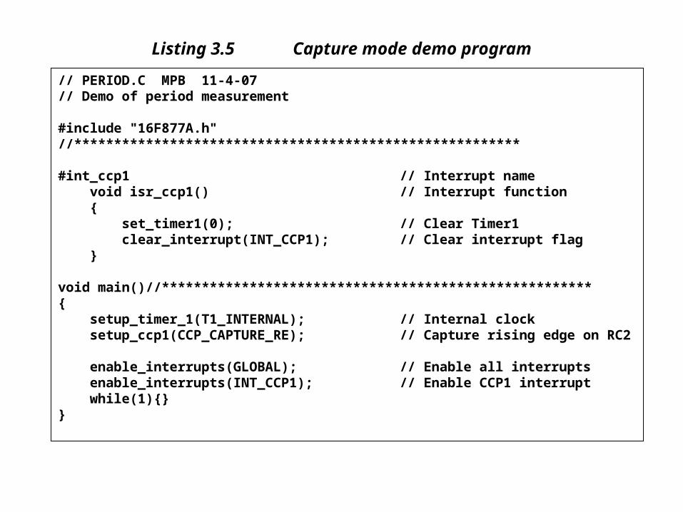
Listing 3.5 Capture mode demo program
// PERIOD.C MPB 11-4-07// Demo of period measurement #include "16F877A.h"//******************************************************** #int_ccp1 // Interrupt name void isr_ccp1() // Interrupt function { set_timer1(0); // Clear Timer1 clear_interrupt(INT_CCP1); // Clear interrupt flag } void main()//******************************************************{ setup_timer_1(T1_INTERNAL); // Internal clock setup_ccp1(CCP_CAPTURE_RE); // Capture rising edge on RC2 enable_interrupts(GLOBAL); // Enable all interrupts enable_interrupts(INT_CCP1); // Enable CCP1 interrupt while(1){}}

Figure 3.6 Capture mode used to measure input period
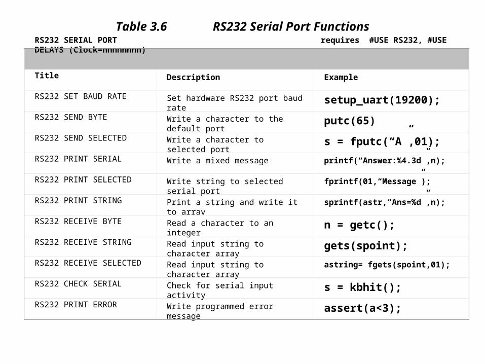
RS232 SERIAL PORT requires #USE RS232, #USE DELAYS (Clock=nnnnnnnn)
Title Description Example
RS232 SET BAUD RATE Set hardware RS232 port baud rate setup_uart(19200);
RS232 SEND BYTE Write a character to the default port putc(65)
RS232 SEND SELECTED Write a character to selected port s = fputc(“A”,01);
RS232 PRINT SERIAL Write a mixed message printf(“Answer:%4.3d”,n);
RS232 PRINT SELECTED Write string to selected serial port fprintf(01,“Message”);
RS232 PRINT STRING Print a string and write it to arrav sprintf(astr,“Ans=%d”,n);
RS232 RECEIVE BYTE Read a character to an integer n = getc();
RS232 RECEIVE STRING Read input string to character array gets(spoint);
RS232 RECEIVE SELECTED Read input string to character array astring= fgets(spoint,01);
RS232 CHECK SERIAL Check for serial input activity s = kbhit();
RS232 PRINT ERROR Write programmed error message assert(a<3);
Table 3.6 RS232 Serial Port Functions

Figure 3.1.1 RS232 peripheral simulation

Listing 3.6 Hardware UART
// HARDRS232.C MPB 13-6-07// Serial I/O using hardware RS232 port #include "16F877A.h"#use delay(clock=8000000) // Delay function needed for RS232#use rs232(UART1) // Select hardware UART void main() //***************************************************{ int incode; setup_uart(9600); // Set baud rate while(1) { incode = getc(); // Read character from UART printf(" ASCII = %d ",incode); // Display it on putc(13); // New line on display }}

Table 3.7 SPI function set
SPI SERIAL PORT
Operation Description Example
SPI SETUP Initialise SPI serial port setup_spi(spi_master);
SPI READ Receives data byte from SPI port inbyte = spi_read();
SPI WRITE Sends data byte via SPI port spi_write(outbyte);
SPI TRANSFER Send and receive via SPI inbyte = spi_xfer(outbyte);
SPI RECEIVED Check if SPI data received done = spi_data_is_in();

Figure 3.8 SPI test system schematic

Listing 3.7 SPI slave transmitter source code
// SPIMASTER.C MPB 20-6-07// Serial I/O using SPI synchronous link// Simulation hardware SPIC.DSN, master program, attach to U1 #include "16F877A.h" void main() //**********************************************{ int number; setup_spi(spi_master); // Set SPI master mode while(1) { number = spi_read(); // Read SPI input BCD code spi_write(number); // Re-send BCD code to slave }}
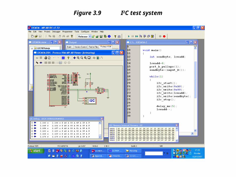
Figure 3.9 I2C test system
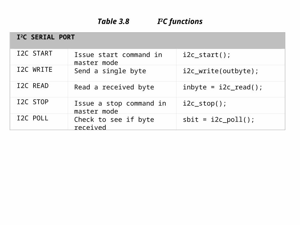
Table 3.8 I2C functions
I2C SERIAL PORT
I2C START Issue start command in master mode
i2c_start();
I2C WRITE Send a single byte i2c_write(outbyte);
I2C READ Read a received byte inbyte = i2c_read();
I2C STOP Issue a stop command in master mode
i2c_stop();
I2C POLL Check to see if byte received sbit = i2c_poll();

Figure 3.10 PSP test system

Table 3.9 PSP functions
PARALLEL SLAVE PORT
Operation Description Example
PSP SETUP Enable or disable PSP setup_psp(PSP_ENABLED);
PSP DIRECTION Set the PSP data direction set_tris_e(0);
PSP OUTPUT READY Checks if output byte is ready to go pspo = psp_output_full();
PSP INPUT READY Checks if input byte is ready to read pspi = psp_input_full();
PSP OVERFLOW Checks for data overwrite error pspv = psp_overflow();

Listing 3.10 PSP master test program
// PSPMASTER.C// Test system master controller program, design file PSP.DSN, U1 #include "16F877A.h" void main() //************************************************{ int sendbyte; port_b_pullups(1); // Activate Port B pullups while(1) { sendbyte = input_B(); // Get test byte output_D(sendbyte); // Output on PSP bus output_low(PIN_E2); // Select PSP slave output_low(PIN_E1); // Write byte to slave port output_high(PIN_E1); // Reset write enable }}