Embed Size (px)
Citation preview

October 2008
NASA/TM-2008-215531
Failure Analysis of Electrical Pin Connectors John A. Newman Langley Research Center, Hampton, Virginia James M. Baughman Lockheed Martin Mission Services Langley Research Center, Hampton, Virginia Stephen W. Smith Langley Research Center, Hampton, Virginia Jeffrey A. Herath Langley Research Center, Hampton, Virginia
https://ntrs.nasa.gov/search.jsp?R=20080043565 2018-06-12T23:07:19+00:00Z

The NASA STI Program Office . . . in Profile
Since its founding, NASA has been dedicated to the advancement of aeronautics and space science. The NASA Scientific and Technical Information (STI) Program Office plays a key part in helping NASA maintain this important role.
The NASA STI Program Office is operated by Langley Research Center, the lead center for NASA’s scientific and technical information. The NASA STI Program Office provides access to the NASA STI Database, the largest collection of aeronautical and space science STI in the world. The Program Office is also NASA’s institutional mechanism for disseminating the results of its research and development activities. These results are published by NASA in the NASA STI Report Series, which includes the following report types:
• TECHNICAL PUBLICATION. Reports of
completed research or a major significant phase of research that present the results of NASA programs and include extensive data or theoretical analysis. Includes compilations of significant scientific and technical data and information deemed to be of continuing reference value. NASA counterpart of peer-reviewed formal professional papers, but having less stringent limitations on manuscript length and extent of graphic presentations.
• TECHNICAL MEMORANDUM. Scientific
and technical findings that are preliminary or of specialized interest, e.g., quick release reports, working papers, and bibliographies that contain minimal annotation. Does not contain extensive analysis.
• CONTRACTOR REPORT. Scientific and
technical findings by NASA-sponsored contractors and grantees.
• CONFERENCE PUBLICATION. Collected
papers from scientific and technical conferences, symposia, seminars, or other meetings sponsored or co-sponsored by NASA.
• SPECIAL PUBLICATION. Scientific,
technical, or historical information from NASA programs, projects, and missions, often concerned with subjects having substantial public interest.
• TECHNICAL TRANSLATION. English-
language translations of foreign scientific and technical material pertinent to NASA’s mission.
Specialized services that complement the STI Program Office’s diverse offerings include creating custom thesauri, building customized databases, organizing and publishing research results ... even providing videos. For more information about the NASA STI Program Office, see the following: • Access the NASA STI Program Home Page at
http://www.sti.nasa.gov • E-mail your question via the Internet to
[email protected] • Fax your question to the NASA STI Help Desk
at (301) 621-0134 • Phone the NASA STI Help Desk at
(301) 621-0390 • Write to:
NASA STI Help Desk NASA Center for AeroSpace Information 7115 Standard Drive Hanover, MD 21076-1320

National Aeronautics and Space Administration Langley Research Center Hampton, Virginia 23681-2199
October 2008
NASA/TM-2008-215531
Failure Analysis of Electrical Pin Connectors John A. Newman Langley Research Center, Hampton, Virginia James M. Baughman Lockheed Martin Mission Services Langley Research Center, Hampton, Virginia Stephen W. Smith Langley Research Center, Hampton, Virginia Jeffrey A. Herath Langley Research Center, Hampton, Virginia

Available from: NASA Center for AeroSpace Information (CASI) National Technical Information Service (NTIS) 7115 Standard Drive 5285 Port Royal Road Hanover, MD 21076-1320 Springfield, VA 22161-2171 (301) 621-0390 (703) 605-6000
The use of trademarks or names of manufacturers in the report is for accurate reporting and does not constitute an official endorsement, either expressed or implied, of such products or manufacturers by the National Aeronautics and Space Administration.

1
Abstract
A study was initiated to determine the root cause of failure for circuit board electrical connection pins that failed during vibatory testing. The circuit board is part of an unmanned space probe, and the vibratory testing was performed to ensure component survival of launch loading conditions. The results of this study show that the pins failed as a result of fatigue loading.
Introduction
A failure investigation was initiated to determine the cause of circuit board failure that occurred during vibration qualification testing for the Mars Science Laboratory Entry Descent and Landing Instrumentation (MEDLI) project. MEDLI is an instrumentation suite installed within the heat shield of the Mars Science Laboratory (MSL) Entry Vehicle. The vehicle was designed to collect data about the Martian atmosphere, Thermal Protection System (TPS) performance, and aerodynamic characteristics of the MSL Entry Vehicle during entry and descent, to provide engineering design data for future Mars missions.
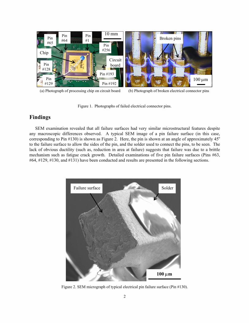
The Sensor Support Electronics (SSE) is mounted on the interior surface of the MSL heat shield. Vibratory testing was performed on these electronics to determine if they would survive the loads associated with their mission (e.g., launch, Martian atmospheric entry). During vibration testing of the SSE, anomalous data was observed. Post-test inspection of the SSE components revealed multiple failures of electrical connecting pins on the circuit board. These electrical pins are constructed from a material commercially known as Kovar1, an alloy primarily composed of iron, nickel, and cobalt, having a coefficient of thermal expansion similar to glass, which is well suited for joining metallic and glass components. The failed pins were removed from the circuit board and examined using scanning electron microscopy. A photograph of the circuit board is shown in Figure 1a, and the processing chip with the failed connector pins is indicated. The processing chip is nominally square with 64 pins per side (256 total pins), and the pins are numbered as indicated in Figure 1a. Approximately 20-30 of these pins failed during vibratory testing. A higher-magnification of typical pin failures is shown in Figure 1b. This paper will present the findings of the microscopic failure surface inspection and discuss observations used to determine the root cause of failure.
Microscopic Examination
A total of five failed connector pins were analyzed that were selected for analysis due to slight macroscopic differences in the appearance of the pins (some were more severely deformed than others) and to analyze pins at different circuit board locations. The cross-section of these pins was nearly square with sides approximately 100 mm long. The pins consisted of Kovar cores that were coated twice, first with pure nickel, followed by an outer layer of gold. These pins were examined at high magnification in a scanning electron microscope (SEM), and chemical composition of selected failure surface features were determined using Energy-Dispersive X-ray spectroscopy (EDX).
1 Kovar, an iron-nickel-cobalt alloy commonly used in electronic applications, is a trademark of Carpenter Technology Corporation.
2
Figure 1. Photographs of failed electrical connector pins.
Findings
SEM examination revealed that all failure surfaces had very similar microstructural features despite any macroscopic differences observed. A typical SEM image of a pin failure surface (in this case, corresponding to Pin #130) is shown as Figure 2. Here, the pin is shown at an angle of approximately 45o to the failure surface to allow the sides of the pin, and the solder used to connect the pins, to be seen. The lack of obvious ductility (such as, reduction in area at failure) suggests that failure was due to a brittle mechanism such as fatigue crack growth. Detailed examinations of five pin failure surfaces (Pins #63, #64, #129, #130, and #131) have been conducted and results are presented in the following sections.
Figure 2. SEM micrograph of typical electrical pin failure surface (Pin #130).
100 µm
Failure surface Solder
Circuitboard
Chip
Broken pins
(a) Photograph of processing chip on circuit board (b) Photograph of broken electrical connector pins
100 µm
10 mmPin#1
Pin#64Pin
#65
Pin#128
Pin#129 Pin #192
Pin #193
Pin#256
3
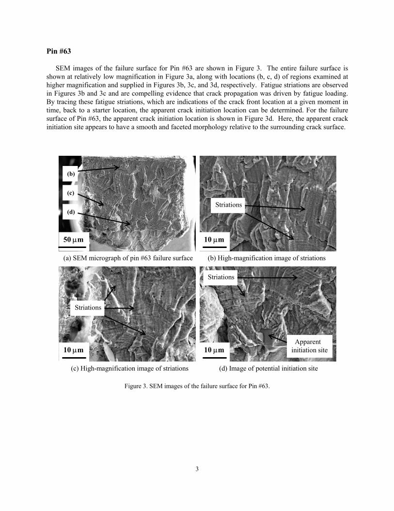
Pin #63
SEM images of the failure surface for Pin #63 are shown in Figure 3. The entire failure surface is shown at relatively low magnification in Figure 3a, along with locations (b, c, d) of regions examined at higher magnification and supplied in Figures 3b, 3c, and 3d, respectively. Fatigue striations are observed in Figures 3b and 3c and are compelling evidence that crack propagation was driven by fatigue loading. By tracing these fatigue striations, which are indications of the crack front location at a given moment in time, back to a starter location, the apparent crack initiation location can be determined. For the failure surface of Pin #63, the apparent crack initiation location is shown in Figure 3d. Here, the apparent crack initiation site appears to have a smooth and faceted morphology relative to the surrounding crack surface.
Figure 3. SEM images of the failure surface for Pin #63.
50 µm
(b)
(c)
(d)
10 µm
10 µm 10 µm
(a) SEM micrograph of pin #63 failure surface
(c) High-magnification image of striations
(b) High-magnification image of striations
(d) Image of potential initiation site
Striations
Striations
Apparent initiation site
Striations

4
Pin #64
SEM images of the failure surface for Pin #64 are shown in Figure 4. The entire failure surface is shown at relatively low magnification in Figure 4a. Locations shown at higher magnification in Figures 4b and 4c are indicated (shown in Figure 4a as locations (b) and (c), respectively). Fatigue striations are observed in Figures 4b and 4c and are compelling evidence that crack propagation was driven by fatigue loading. An interesting feature observed in Figure 4c (indicated as location (d)) is shown at higher magnification in Figure 4d. This feature appears to be a particle, but the crack surface features do not suggest that this is a crack initiation site. No obvious crack initiation site was found on this crack surface.
Figure 4. SEM images of the failure surface for Pin #64.
50 µm
(b)(c)
(d)
(a) SEM micrograph of entire failure surface (b) High-magnification image of striations
30 µm
(c) High-magnification image of striations (d) Higher-magnification image of striations
10 µm 5 µmStriations
Striations
Particle
Particle
Striations

5
Pin #129
SEM images of the failure surface for Pin #129 are shown in Figure 5. The entire failure surface is shown at relatively low magnification in Figure 5a. Locations indicated in Figure 5a as (b), (c), and (d) are shown at higher magnification in Figures 5b, 5c, and 5d, respectively. Fatigue striations are observed in Figures 5b and 5c and are compelling evidence that crack propagation was driven by fatigue loading. These crack surface features can be used to determine the apparent crack initiation region, which is shown in Figure 5d. Similar to the findings for Pin #63, the apparent crack initiation site appears to have a smooth and faceted morphology relative to the surrounding crack surface.
Figure 5. SEM images of the failure surface for Pin #129.
(b)
(d)
(c)50 µm 50 µm
5 µm10 µm
(a) SEM micrograph of pin #130 failure surface (b) High-magnification image of striations
(c) High-magnification image of striations (d) Image of potential initiation site
Striations
Striations
Apparent initiation site

6
Pin #130
SEM images of the failure surface for Pin #130 are shown in Figure 6. The entire failure surface is shown at relatively low magnification in Figure 6a. Locations indicated in Figure 6a as (b), (c), and (d) are shown at higher magnification in Figures 6b, 6c, and 6d, respectively. Fatigue striations are observed in Figures 6b and 6c and are compelling evidence that crack propagation was driven by fatigue loading. These crack surface features can be used to determine the apparent crack initiation region, which is shown in Figure 6d. Similar to the findings for Pins #63 and #129, the apparent crack initiation site appears to have a smooth and faceted morphology relative to the surrounding crack surface.
Figure 6. SEM images of the failure surface for Pin #130.
(b)
(c)
(d)
50 µm 5 µm
5 µm5 µm
(a) SEM micrograph of pin #130 failure surface (b) High-magnification image of striations
(c) High-magnification image of striations (d) Image of potential initiation site
Striations
Striations
Apparent initiation site

7
Pin #131
SEM images of the failure surface for Pin #131 are shown in Figure 7. The entire failure surface is shown at relatively low magnification in Figure 7a. Locations indicated in Figure 7a as (b), (c), and (d) are shown at higher magnification in Figures 7b, 7c, and 7d, respectively. Fatigue striations are observed in Figures 7b and 7c and are compelling evidence that crack propagation was driven by fatigue loading. These crack surface features can be used to determine the crack initiation region, which is shown in Figure 7d. Similar to the findings for Pins #63, #129, and #130, the apparent crack initiation site appears to have a smooth and faceted morphology relative to the surrounding crack surface.
Figure 7. SEM images of the failure surface for Pin #131.
Chemical Analysis of Crack Initiation Sites
The difference in crack surface morphology of the apparent crack initiation sites, compared with the surrounding crack surfaces, suggested that a different damage mechanism may have occurred in these regions. The crack intiation sites identified for Pins #63 and #130 were chemically analyzed using Energy Dispersive X-ray (EDX). The results of this chemical analysis are presented in Table 1, along with the nominal composition of Kovar for comparison (ref. 1). Of the main alloying element of Kovar (iron, nickel, and cobalt), these crack initiation sites had very low nickel content relative to the nominal composition of Kovar. The nominal composition of Kovar presented in Table 1 is for the gamma (γ) phase of this alloy, an FCC condition that is widely used in the electronics industry (ref. 1). However, an
50 µm 25 µm
(a) SEM micrograph of pin #131 failure surface (b) High-magnification image of striations
(c) High-magnification image of striations (d) Image of potential initiation site
(b)
(c)
(d)
10 µm 5 µmApparent
initiation site
Striations
Striations

8
undesirable nickel-poor alpha (α) phase can occur, especially as the temperature of this alloy approaches 500oC. The reduction in nickel content is typical of that expected for a gamma-to-alpha phase transformation in Kovar (ref. 2). It is possible the temperatures reached during the soldering process may have triggered an unintended alpha-phase transformation. Based on the crack surface analysis, the presence of this alpha-phase serves as crack initiation sites thereby decreasing the fatigue resistance of the Kovar electrical pin connectors.
Table 1. Chemical composition of crack initiation sites compared with nominal values for Kovar.
Summary
Microscopic features found on the failure surfaces of electrical pin connectors revealed that the failure was the result of fatigue crack propagation. Crack front markers, such as striations, indicated that crack initiation occurred at features that appeared to be smooth and faceted (typically an indication of brittle failure). A chemical analysis revealed that these features associated with crack initiation had very low nickel content in comparison to the surrounding matrix. Although not proven, and outside the scope of this investigation, it is possible that these nickel-poor regions are an unintended second phase that may have formed as a result of component processing such as soldering the electrical connectors (heat).
References
(1) V.A. Fedorovich, V.A. Makarov, T.G. Korotkova, A.I. Rad’kov, and K.V. Trush, “Structural Transformations of FCC-phases in “Kovar” Alloy During Heating,” Translated from Metallovedenie i Termicheskaya Obrabotka Metallov, No. 3, pp. 54-55, March, 1981.
(2) V. Raghavan, “Co-Fe-Ni (Cobalt-Iron-Nickel),” Journal of Phase Equilibria, Vol. 15, No. 5, 1994, p. 526.
Crack initiation site Crack initiation site Kovar Pin #63 Pin #130
Element (weight %) (weight %) (weight %)
Iron, Fe Balance (53.5) 65.55 63.02Nickel, Ni 29.00 11.20 16.50Cobalt, Co 17.00 20.54 19.77Silicon, Si 0.20 - -
Manganese, Mn 0.30 - 0.51Aluminum, Al - 1.98 0.19
Copper, Cu - 0.73 -

REPORT DOCUMENTATION PAGE Form ApprovedOMB No. 0704-0188
2. REPORT TYPE Technical Memorandum
4. TITLE AND SUBTITLEFailure Analysis of Electrical Pin Connectors
5a. CONTRACT NUMBER
6. AUTHOR(S)
Newman, John C.; Baughman, James M.; Smith, Stephen W.; and Jeffrey A. Herath
7. PERFORMING ORGANIZATION NAME(S) AND ADDRESS(ES)NASA Langley Research Center Hampton, VA 23681-2199
9. SPONSORING/MONITORING AGENCY NAME(S) AND ADDRESS(ES)National Aeronautics and Space AdministrationWashington, DC 20546-0001
8. PERFORMING ORGANIZATION REPORT NUMBER
L-19544
10. SPONSOR/MONITOR'S ACRONYM(S)
NASA
13. SUPPLEMENTARY NOTES
12. DISTRIBUTION/AVAILABILITY STATEMENTUnclassified - UnlimitedSubject Category 26Availability: NASA CASI (301) 621-0390
19a. NAME OF RESPONSIBLE PERSON
STI Help Desk (email: [email protected])
14. ABSTRACT
A study was initiated to determine the root cause of failure for circuit board electrical connection pins that failed during vibatory testing. The circuit board is part of an unmanned space probe, and the vibratory testing was performed to ensure component survival of launch loading conditions. The results of this study show that the pins failed as a result of fatigue loading.
15. SUBJECT TERMSFailure analysis; Fatigue crack growth
18. NUMBER OF PAGES
1319b. TELEPHONE NUMBER (Include area code)
(301) 621-0390
a. REPORT
U
c. THIS PAGE
U
b. ABSTRACT
U
17. LIMITATION OF ABSTRACT
UU
Prescribed by ANSI Std. Z39.18Standard Form 298 (Rev. 8-98)
3. DATES COVERED (From - To)
5b. GRANT NUMBER
5c. PROGRAM ELEMENT NUMBER
5d. PROJECT NUMBER
5e. TASK NUMBER
5f. WORK UNIT NUMBER
329231.01.07.04.50
11. SPONSOR/MONITOR'S REPORT NUMBER(S)
NASA/TM-2008-215531
16. SECURITY CLASSIFICATION OF:
The public reporting burden for this collection of information is estimated to average 1 hour per response, including the time for reviewing instructions, searching existing data sources, gathering and maintaining the data needed, and completing and reviewing the collection of information. Send comments regarding this burden estimate or any other aspect of this collection of information, including suggestions for reducing this burden, to Department of Defense, Washington Headquarters Services, Directorate for Information Operations and Reports (0704-0188), 1215 Jefferson Davis Highway, Suite 1204, Arlington, VA 22202-4302. Respondents should be aware that notwithstanding any other provision of law, no person shall be subject to any penalty for failing to comply with a collection of information if it does not display a currently valid OMB control number.PLEASE DO NOT RETURN YOUR FORM TO THE ABOVE ADDRESS.
1. REPORT DATE (DD-MM-YYYY)10 - 200801-