Embed Size (px)
Citation preview

MARNOLD
POWER SUPPLIES
FOR YOUR MODEL TRAIN
ELECTRICAL COMPONENTS
the LEYGHTON·PAIGE CORP. SPRING PARK, MINNESOTA
lit EDITION

MARNOLD
POWER
For Your
Model Railroad
Written and Edited by:
K.N.RAO CLARK E. JOHNSON
DAVID WIGGINS
Copyright 1960
THE LEYGHTON-PAIGE CORPORATION
Spring Park, Minnesota

MARNOLD POWER For Your
Model Railroad
FIRST PRINTING, JANUARY, 1960
Printed in the United States of America
by Rei Graphic Services Inc., Minneapolis, Minn.

Table of Contents
CHAPTER 1 Electrical Components in Your Layout ............................................................. 1
CHAPTER 2 Power Packs-Their Selection and Care ......................................................... 3
CHAPTER 3 The Marnold System of Power Supplies and Electrical Components ......... 5
CHAPTER 4 Basic Power Supplies, B-25, B-45, and B-BS ................................................... 7
CHAPTER 5 Complete Power Packs, C-25-B, C-40-B, C-SO-B, and C-50-B Special ...... 9
CHAPTER 6 Complete Power Pac
CHAPTER 7
pecial Units-4250, 5250, 5254 .......................... 12
Super Packs-Super 1, Super 2, and Super 3 (Dual Control ) .................... 15
CHAPTER 8 Throttle Cab Control Units .................................................................................. 18
CHAPTER 9 Instructions for Wiring of Reverse Loops with C-25-B, C-40-B, and C-50-B Power Packs ....... .. ........... .... ..... . .......................... 20
CHAPTER 10 Marnold Ad-A-Panel Series-Basic Framework
CHAPTER 11
22
Power Panels for Ad-A-Panel Mounting ................................................... 26
CHAPTER 12 Throttle Cab Control Panels for Ad-A-Panel Mounting ........................... .. 27
CHAPTER 13 Transformers and Rectifiers ............. ........... ................... ................................ . 29
CHAPTER 14 Marn-o-stats and Load ompensators ........................................ ................ 31
CHAPTER 15 Marn-o-meters and Rotary Reversing Switch ......... .................................... ... 34
CHAPTER 16 The VX Meter Switch ............................................................................ 37
CHAPTER 17 Paigelite High Frequency Lighting ........................................................... 40
CHAPTER 18 The Terminal Strip ...................... ....... .......................................................... 43

Foreword
This book is dedicated to model railroaders of all ages everywhere. Over the years the Marnold line of power supplies and electrical components has gained the reputation of being the simplest add-on system ever designed for model railroads. In this booklet an attempt is made to d cribe the system in simple language, so that all model railroaders, irrespective of their technical backgrounds, can follow the system.
Many improvements have been made in the Marnold line of power supplies since 1945. We are confident that you will derive a great deal of fun and satisfaction in using this ingenious system of power supply units and throttle cab controls, which can grow as your layout grows.
Model railroading is fun and the Marnold equipment will certainly add to your enjoyment of this hobby.
The LEYGHTON-PAIGE CORPORATION
Spring Park, Minnesota

CHAPrER I C!~
Electrical Components in Your Layout
ELECTRICAL CURRENT
There are two kinds of electrical current . . . alternating current and direct current. Direct current is recommended for electric trains because of the better control direct current gives at lower voltages.
All HO and 0 gauge model railroads run on direct current. In this kind of current, commonly known as D.C., the flow of electrons, which produces the current, is always in the same direction.
Power from a dry cell or from an automobile battery is direct current. How is this power different from power used for lighting a house? Housepower is normally alternating current or A.C. In this kind of current, the magnitude and direction of the current varies with perfect regularity. All the changes of direction take place similarly over given time periods. For example, a 60-cycle alternating current is one in which the positive and the negative flow of the current repeats itself regularly every 1I60th of a second. The changes that take place during the positive half of the cycle are repeated in the negative half. The rate of change is called frequency and is usually measured in cycles per second. Common housepower in the United States is 110 volts, 60-cycle A.C. Many overseas countries use 220 volts, 50-cycle A.C. current.
PULSE POWER
In model railroad work, one frequently comes across a special kind of power called "Pulse Power." The principle of pulse power is used in some of the Leyghton-Paige power packs ( i.e., the Super Packs ) described later in this book. In this kind of power, the current changes regularly from instant to instant with periods of no voltage in between, but it does not change direction. This is a kind of direct current, but it is not continuous. The current is delivered in rapidly spaced pulses. These pulses, as we shall see later, help make possible slow even starts and stops of model trains. The pulse power used in LeyghtonPaige Super Packs automatically changes to continuous D.C. as the throttle is advanced.
ELECTRICAL CONVERSION
House voltage is too powerful for model railroad operation. Not only does the voltage need to be reduced, but it also needs to be changed from A.C. to D.C. Voltage is reduced by using a transformer. A.C. current is changed to D.C. by using a rectifier.
The Marnold Power Packs described in this booklet convert housepower at 110 volts A.C. to a low voltage of 12 volts D .C. at various amperages.
The ampere is a measure of the strength of the current. The amperage ratings of the Marnold Power Supplies range from 2lh to 8112 amperes. The greater the amperage of the power supply, the more trains that can be run with it.
Amperes, volts, and watts can be compared to a waterpipe for simpler understanding. Amperage is the diameter of the pipe. Voltage is the water pressure and watts is the output. Watts - Amperes Times Volts.
TRANSFORMER
In model railroad layouts, A.C. is used for lighting, switch machine3 and operating other accessories. Locomotives run only on D.C. power fed to the tracks. Most of the power packs are so designed that the A.C. for accessories and D.C. for trains can be tapped from the same transformer. In order to help you understand how this is possible, a brief description of transformer action is given below.
When a current flows through a coil of wire, a magnetic field is produced around the coil. This is an important property of electricity. When a coil carrying A.C. is brought close to another coil, the magnetic field generates a voltage in it. The two coils are not physically connected together; in fact, they are insulated from each other. But, magnetically, they are coupled together. Thus, in a transformer, the coil carrying the A.C., called the primary, transfers electrical power to a second coil called the secondary by means of an alternating magnetic field. Transformers used in model railroad work are all "stepdown" transformers because they reduce the high voltage of 110 volts or 220 volts to about 12 volts, as specified by the National Model Railroad Association.
1

Electrical Components in Your Layout
The voltage induced in the secondary of the transformer depends upon the ratio of the number of turns in the secondary to the number of turns in the primary. In the stepdown transformer, there are less
110 VOLTS
A.C.
200 TURNS
PRIMARY
turns of wire in the secondary than there are in the primary. In the step-up transformer, the reverse is true.
20 TURNS
SECONDARY
20 SECONDARY VOLTAGE = -- x 110
200
= 11 VOLTS
Fig 1·1
In the transformer, the coils are wound around a core of magnetic metal stampings called laminations. The ability of the magnetism to pass through the material used in the core is important,since all the magnetism goes through the secondary. If no iron was used, much magnetism would be wasted in the air and the transformer would be very inefficient.
It is possible to design transformers so that in a single transformer, there are two primaries and two secondaries or one primary and two secondary connections.
RECTIFIER
In model railroad work, it is usual to design transformers so that a reduced A.C. voltage output is available for operating accessories and to "rectify" part of the A.C. output to give D.C. to run trains.
What then is "rectification" of the A.C. to the D.C.? The rectifier is the device which changes A.C. to D.C. current. It permits the current to flow in only one direction. When A.C. tries to flow through it, the current flows for only half of each cycle of the alternating current.
2
Rectifiers are usually combinations of certain metallic materials pressed together and the properties of the combined materials make for rectifier action. Dry metal rectifiers of iron or aluminum coated with selenium are commonly used in model railroad power packs.
Selenium rectifiers are very rugged and have almost unlimited life if not used above their ratings. Solid state rectifiers such as silicon and germanium are small efficient rectifiers which may largely replace selenium before too long. They do not have the shorttime overload capabilities of selenium, however.
Power packs used in model railroading consist of a transformer to reduce the housepower from 110 volts to a low, safe 12 volts and a rectifier to change the A.C. to D.C.
RHEOSTAT
When a variable resistance coil, commonly known as a rheostat or throttle control is included in the power pack, then there are means of controlling the voltage output and hence the speed of the trains. In the Marnold line of power packs, the throttle controls can be bought separately or included in a complete power pack.

CHAPl'ER II
Power Packs--Their Selection and Care
Power Packs can be purchased in different sizes and ratings. The number of power packs to be used in your layout depends upon the number of trains you propose to run. It is generally figured that one ampere is needed to run an average train consisting of a locomotive with six to eight cars. Consult your Mamold dealer before making an investment in power supplies.
The Mamold System is designed to be an add-on system to grow with your layout. Be sure to begin with the simplest basic pack and add the components as you need them.
AMPERAGE DRAW OF AVERAGE LOCOMOTIVES
Tests have been made on standard locomotives, presently marketed, to measure their amperage consumption under maximum operating conditions. Below are the results which should be carefully considered when purchasing your power pack. All ratings are at 12 volts D.C. The following chart is reproduced with some changes from the book "How to Wire Your Model Railroad" 5th edition Kalmbach Publishing
ompany.
MOTOR CURRENT RATINGS
If you operate a motor at not more than the current values listed, you should have no overheating. In most ratings a 20 per cent safety factor is included to allow for variations in individual motors and ammeters. Voltage has little to do with motor heating.
SAFE CURUNT MAKE AND MODEL AM;ERES
1.0 1.5 2.0
All -Nation, old ... motors, ob.olete Pillman DC-92, DC-94 ...... _ .. _ .. _ Pillman DC-95
American flyer (S .eale) Small motor Large motor Di.s.1 motors, each . Add for .moke unit ..
Athearn, small motor .. __ .. __ .~ Large motor ..... ___ .. _._
Baldwin Locomotive. law, .. , all modol. Control locomotive Work.
PiHman DC-95A flei.chmann Gilbort (HO .eolo.)
0.85 1.5 1.2 0.4 0.5 0.8· 1.3 0.7
2.0 0.25
Penn .witche. .. .. _ .... _ .. _ .. ___ .. _ ... _._. 0 .8 Hud.on loco __ .. _____ . 1.0 Alco die.el ._._ .. __ 1.2 GM die.el A unit .. __ .. __ ...... _........ 1.0 Indu.trial .witche. 0.7 Add for .moke unit 0.3
H ... kimer, use. Athearn motor 0.6* Hobby town, Pillman DC-70 0.7 H. P. Product., Romford Midgot __ .... 0.5 Kemlron, Thoma. flyer 0.5
(Lindsay motors have L numbers; model. u .. Pjllman motors) l -170, l -180 (d i.continued) l - l90 .. l -570, l -580, l -582 ..... l -740 Kl-766 l -1010, l -1030 (di.continued) ___ ... l -1045 (di.continuod) .. 00·666 PM-l0 TT-l05 X-130, Romford Midget ........... __ _ X-JOO, Romford Phantom X-JOI , Micro ...
lome
0.8 0.7 0.5 0.1 0.5 0.5 0.8 0.8 0.5 0.5 0.5 0.5 0.5
Kondrick & Davi., 117· 1 117·2 117·3 117·4
Kidder, Japane,. imports Ku.an Auburn 0 Gaugo .
2.0 2.8 4.0 5.0 0.8· 0.75
lind.ay (now Komtron ; ... l numb .... ) lionol, HO, 1959· 1960 modol. 0.5
2.5 1.75 2.75 4.0 0.6 0.6 0.6 0.6 0.7
o gauge and 0 ·27 gaugo __ _ lobaugh, 6100 __ _
6200 6300
Mantua, 3352 (.mall) 33565 (Gonoral tend~r motor) 33572, 33573, PM· l Oie.el pow or truck . 33574, 33575 (Pittman DC·70)
Miller (S .ealo powor truck), per armature Aftor .tarting, current .hould bo
Modol Dio Ca.ting, Pillman DC·6O DC·62A ... formorly u.ed lindlOY motor
Modol Engin_ing Works Pillman DC-6O formorly u .. d lind.ay motor
Mod.1 Pike, DC-60 Modol Tramway Sy.tem Nard, Ml Pacific fa.t Mail, Ton.hodo, MV-l
MH -2, MH -3 United, DC-195 DC-295 Pillman DC-70 DC-62A ... DC-711 .
Ponn line (u.o. Pillman motor.) Ponn.ylvania Sealo Madol.,
ES-16O dio.ol Trudia" motor ' ..
Pillman (rubbor-band roplacomont motor) DC-62A .. DC-6O, DC-62, DC-65
1.0 lower.
0.7 0.6 0.5
0.6 0.5 0.7 0.6 1.35 0.75 1.0 0.5 0.95 0.7 0.6 0.8
0.5· 0.5·
0.6 0.6
DC-70 __ . __ ......... 0.7 DC-703 __ .. __ .. _ ............. 0 .6 DC-702 (Early RDC car.). __ .. _ .. _ .. __ .. _ ....... 0.5 DC-71A, DC-711 ____ .. ....... 0.8 DC-80 (ob.oloto) _ ..... ___ ... _ ............. 0 .85 DC-81, DC-85 .. .. _____ ..... 1.0 DC-91 ___ ..... 1.3 DC-92, DC-94 (ob.oloto) .. _ .... _ .............. 1.5 C-93, DC-9.5 (ob.oloto) ___ ....... 2.0 DC-94A (d i.cantinuod) ... _ .. _ .. _ .. _... ... 1.5 DC-95A .. 2.0 DC-l00 3.0 DC-204A, 0 gaugo trolloy truck .. 0 .7 AC-92, AC-94 (ob.olote) 1.2 AC-93 (ob.alete) .. 1.8 AC-95 (ob.olete) .. __ .. __ .. _ 1.8
Revoll, die.el loco motor Switch.r motor Add for .moke unit
0 .6-.... 0 .6·
0.3· Rivaralll _____ 0.5· Romford, Phantom, etc. (.ee H. P.
Product. or Kemtron) Roundhou .. (.ee Model Die Ca.ting.) Sim., Pillman DC-71 I .... 0.8
Japono.e motor 0.6· Suydam, HO, S-I43 1.0 Ton.hodo ( ... Pacific fa.t Mail) Thoma. (u.o. Pillman Motors) Tyco (.ame a. Mantua) United ( ... Pacific fa.t Mail) Varnoy, all .mallor loco. are
Pillman DC-6O .. ____ ... 0 .6 f -3 die.el, Pittman DC-70 .. ___ ....... 0 .7 Berk.hire, heavy Con.olidotion,
Pillman DC-71 I .... _ ......... 0.1 formorly .upplied own motors .. 0.75
Wagner, Pillman DC-6O 0.6 Pillman DC-711 .......... _..... 0.8 Pillman DC-94 .... _ .... __ .... 1.5
Walthers, HO power truck, Pillman DC-6O 0.6 o .cale truck u.e K&D motor
·E.timoted-no verification received
3
C® Power Packs-Their Selection and Care
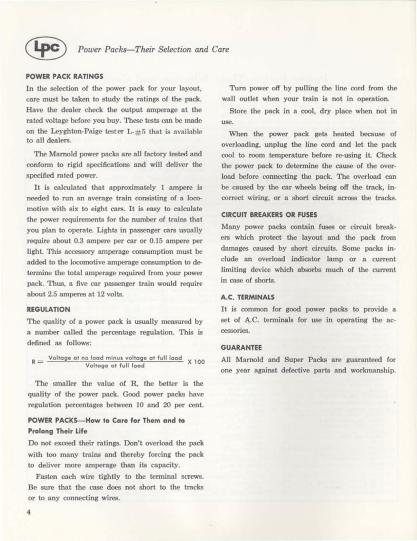
POWER PACK RATINGS
In the selection of the power pack for your layout,
care must be taken to study the ratings of the pack.
Have the dealer check the output amperage at the
rated voltage before you buy. These tests can be made
on the Leyghton-Paige tester L-#5 that is available to all dealers.
The Mamold power packs are all factory tested and
conform to rigid specifications and will deliver the
specified rated power.
It is calculated that approximately 1 ampere is
needed to run an average train consisting of a loco
motive with six to eight cars. It is easy to calculate
the power requirements for the number of trains that
you plan to operate. Lights in passenger cars usually
require about 0.3 ampere per car or 0.15 ampere per
light. This accessory amperage consumption must be
added to the locomotive amperage consumption to de
termine the total amperage required from your power
pack. Thus, a five car passenger train would require
about 2.5 amperes at 12 volts.
REGULATION
The quality of a power pack is usually measured by
a number called the percentage regulation. This is
defined as follows:
R = Voltage at no load minus voltage at full load X 100 Voltage at full load
The smaller the value of R, the better is the
quality of the power pack. Good power packs have
regulation percentages between 10 and 20 per cent.
POWER PACKS-How to Care for Them and to
Prolong Their Life
Do not exceed their ratings. Don't overload the pack
with too many trains and thereby forcing the pack
to deliver more amperage than its capacity.
Fasten each wire tightly to the terminal screws.
Be sure that the case does not short to the tracks
or to any connecting wires.
4
Tum power off by pulling the line cord from the
wall outlet when your train is not in operation.
Store the pack in a cool, dry place when not in
use.
When the power pack gets heated because of
overloading, unplug the line cord and let the pack
cool to room temperature before re-using it. Check
the power pack to determine the cause of the over
load before connecting the pack. The overload can
be caused by the car wheels being off the track, in
correct wiring, or a short circuit across the tracks.
CIRCUIT BREAKERS OR FUSES
Many power packs contain fuses or circuit break
ers which protect the layout and the pack from
damages caused by short circuits. Some packs in
clude an overload indicator lamp or a current
limiting device which absorbs much of the current
in case of shorts.
A.C. TERMINALS
It is common for good power packs to provide a
set of A.C. terminals for use in operating the ac
cessories.
GUARANTEE
All Mamold and Super Packs are guaranteed for
one year against defective parts and workmanship.

CHAPl'ER III c® The Marnold System of Power Supplies and Electrical Components
Marnold is the oldest and most experienced manufacturer of quality power equipm nt for model railroads and toy trains. In the last fifteen years the System ha found its way into mo t railroader's homes, into modem railroad clubs and even into model railroad museums.
This is, in part, due to the ingenious system of power supply units and throttle cab control units which can be added on as your layout grows. In the Mamold Ad-A-Panel series, sectional framework units and control panel assemblies of modular construction can be built to any size for operating a simple track layout to a complete system of mainlines. yarde;. and sidings. The power pack can grow as your railroad grows.
In the following paragraphs. the Marnold system is described. In succeeding chapters of the book. Marnold power units and accessories are described in detail with wiring diagrams and operating instructions.
Marnold has been operating as a division of the Leyghton-Paige Corporation since July. 1958, and there are now two different and distinct Mamold systems:
A-Bridge Rectifier System: The first Marnold System and the system in all units purchased from the Marnold Company in West Chicago before July, 1958.
B-Full Wove Center Tap Rectifier System: The improved Marnold system designed by Leyahton-Paige and in all units manufactured after July, 1958.
The two systems differ only in the use of transformers and rectifiers. The transformers and rectifiers whose numbers are followed by A should be used in the old Marnold A system the bridge rectifier system. Those whose numbers are followed by B should be used in the new Mamold system- the full wave center tap rectifier system.
A B Full wove
Bridge System center top system
Produd Description Cat. No. Unit Cat. No. Unit
I. Transformers L#110 S6·8A L#22 T-3B
L#lll S6-9A L#23 T-SB
L#1l2 S8·3A L#24 T-IOB
L#1l3 S9-SA L#1l8 T-4B
L#IOS (Spec.) T-SB
2. Rediflers L#108 X-2SA L#2S X-2SB
L#109 X-4SA L#26 X-4SB
L#27 X-8SB
3. Power Packs C-2S-A L#16 C-2SB
C·40·A L#17 C·40B
C·SO·A L#84 C-SOB
* C·SO·A Spec. L#88 (Spec.) C..sOB
42SO·A L#18 42S0B
S2S0·A L#8S S2SOB
S2S4·A Spec. L# 119 (Spec.) S2S4B
4. Power SUppliM B.2SA L#13 B·2SB
and Panels B·4SA L#U B.4SB
B·8SA L#IS B·8SB
* M-20A L#S6 M·20B
M·40A L#S7 M·40B
J·IPA L#107 J-IPB
*No longer manufactured.
All products whose numbers are not followed by either A or B, are units that can work with both systems.
B SYSTEM-FULL WAVE CENTER TAP RECTIFIER
When the Mamold line was introduced in 1945, the selenium rectifier was a relatively crude device compared with those of today. For example, selenium plates were limited to 26 volts per plate and the current maximum was about 200 milleamperes per square inch. This meant that all rectifiers had to be of the "birdge" type. For a 21f2 ampere unit, such as is used in the Marnold C-25 power pack, each plate had to be 6 square inches in area.
Today, selenium cells can operate up to 36 volts (even more from a few manufacturers) and curr nt densities are doubled to 400 milleamperes per square inch.
This allows use of a full wave center-tapped circuit which is shown in figure 3-1 compared to the standard bridge arrangem nt shown in figure 3-2.
5

® The Marnold System of Power Supplies and Electrical Components
TRANSFORMER RECTIFIER
16 VOLTS
D.C. 16 VOLTS LOAD 12 VOLTS
Full Wave Center Tap Circuit
Fig. 3-1
You will note that there is only one cell in the circuit with the full wave center-tapped circuit compared to the two cells in the bridge circuit. This means regulation is much improved, since the rectifier cells are the primary source of poor regulation. You will also note in figure 3-1 that each cell carries the same average current in both circuits.
The other improvement in the Marnold system is the adoption of a alUminum core tube for the MarnO-Stats, the well-known Marnold rheostat. The newly dC3igned rheostat can now withstand larger overloads.
THE MARNOLD BASIC POWER SUPPLIES
are designated by the prefix B (i.e., B-25, B-45, B-S5 ) . These units are deluxe D.C. power supplies and contain a transformer and selenium rectifier for various amperage outputs. These power supplies are designed for use with separate throttle cab control units for train control, depending upon the train, (i.e., HO gauge, 0 gauge or S gauge). A basic power supply together with a throttle cab control unit make up a complete power pack. Complete descriptions with instructions are given in Chapter IV.
THE MARNOLD COMPLETE POWER PACKS
are designated with the prefix C, ( i.e., C-25, C-40, C-50). These units contain a transformer, rectifiers, built-in Marn-O-Stat lever action throttle control, and a fuse-type circuit breaker. These units are ready for connection to the track. Terminals are clearly marked for controlled D.C. output, fixed D .C. output, A.C. output for accessories, and reverse loop connections. Complete descriptions with instructions are given in Chapter V.
THE MARNOLD AD-A-PANEL SERIES
consists of sectional framework units and control
6
TRANSFORMER
~ 16 VOlTS
LOAD
12 VOLTS
Bridge Circuit
Fig. 3-2
panel assemblies that can be fitred together to give a versatile control panel.
For example, a HO 30P throttle cab control panel can be mounted to a C-40-B power pack to give a dual control system. A meter panel can be added also next to the C-40 and HO 30P for power measurements and trouble shooting on your layout. Even the High Frequency Lighting Panel can be mounted next to the meter panel to operate the train lights independently of the train power. Additional power packs and throttle cab control units can be added whenever you expand your layout.
The Marnold system of power packs and throttle cab control units give you a versatile combination for every model railroad need. You can run a simple layout with one train on one loop or a complex system of many trains and loops with the Marnold individual power packs and the Ad-A-Panel series of power accessorie3.
The Marnold throttle control units are well-known to model railroaders everywhere. Its vernier-like action makes for smooth gliding stops and starts, prototypical to real trains. The rheostat controls the D.C. output and hence the speed of the train. At the full throttle position, the resistance is at zero so the train receives the maximum available voltage D.C. output from the pack. At the minimum position of the throttle, the resistance in the circuit reaches a maximum and the train therefore comes to a stop. Since there is always some current flowing through the resistance coils, sudden starts and stops are avoided.
The action of the throttle control is further improved by the use of a load compensator. This is an additional resistance coil in series with the throttle control and adjusts the rheostat for differences in train loads or the power consumption of the various types of locomotives.

CHAPrER IV C!@ Basic Power Supplies, B-25, B-45, and B-85
8-25 8-45
APPLICATION The "B" series of Marnold basic power supply units are specially designed for model railroad use. Each unit is equipped with a high quality transformer and
..
8-85
rectifi r assembly. The units are available in three models depending upon amperage output required. Throttle cab control units can easily be added to each basic power supply for variable speed control.
SPECIFICATION TABLE
D.C. Power A.C. Power Catalog Unit
Volts No. Amps Amps
l#13 B-25 21/2 12 21/2
l#14 8-45 41/2 12 41/2
l#15 B-85 81/2 12 81/2
NOTE: Power ratings are conservative
• Use all Power Units only with Input power rated at 110/120 volts and 50/60 cycle A. . only.
• Use one Marn-O-Stat Cab ontrol for each track circuit.
Volts
16
16
17
Marnostat For No. of Dimensions Cab Control
Gauges Trains of Case Recommended
HO H030l 00 2-3 3"x3 1/2 "x61/2" H030l
TT H030l
HO 4-5 H020l 00 3-4 H020l S 2-3 3"x31/2 "x61/2 " S20l 0 2-3 010l
HO 7-10 H030l 00 6-7 H030l S 4-6 5"x6"x9" S20l 0 4-6 010l
• Model numbers of units are indicative of rated amperage output, (i.e., B-25 puts out 2% amps).
• All units housed in attractive, durable, brown hammerloid fini hed metal case .
• Binding posts, fuse, lin cord plug all located in convenient positions.
7

Basic Power Supplies, B-25, B-45, and B-85
FEATURES
The B-25 is a basic unit and is designed for the average model railroad consisting of one or two trains. It will operate three trains intermittently. Use a throttle cab control with the B-25 to control the speed of the train. The HO 30L cab control unit is recommended for this purpose. This throttle control has a 30 ohm rheostat, a reversing switch and a load compensator. Two or more of these combinations can be used in a multiple pack system. That is, a B-25 and a throttle control for each track and one for the yards. These additional units can be purchased as your railroad grows.
a-85 UNIT
TO
1.
2.
3.
4.
5.
PARTS LIST
Transformer
Rectifier
On-Off Switch
Fuse
Fuse Holder
SWITCH MACHINES, LIGHTS, ETC.
Fig. 4-2
CONNECTION
8-25
l # 22
l # 25
l # 95
l # 36
l # 12P
Connect the D.C. output from the power supply to the
input D.C. terminals of the throttle cab control cabinet. Connect the D .C. output from the throttle cab control cabinet to the track. The A.C. output can be
8
RECTIFIER
D.C. TO TRACKS
INSTRUCTIONS
B-45
l# 23
l# 26
l# 95
l# 36
l# 12P
WIRING DIAGRAM
A .C. ACCESSORIES
TRANSFORMER
ON·OFF SWITCH
B-Serie. Power Packs Fig. 4-1
B-85
l# 24
l# 27
l# 95
l# 37
l# 383P
H030l THROTTLE CONTROl
connected to the accessories (lights, switch machines, etc.) .
It is suggested that the B-85 unit be used for S gauge and 0 gauge, especially when two or more trains are to be run continuously at the same time.

•
CHAPl'ERV ® Complete Power Packs, C-25-B, C-40-B, C-50-B, and C-50-B Special
C·2SB C-40B C·SOB
APPLICATION
The Marnold Complete Power Packs include the transformer, rectifier, rheostat and a reversing switch. These precision built power packs are produced with several power output ratings and are completely
Catalog D.C. Power A.C. Power
Unit No. Amp. Volts Amp. Volt.
L# 16 C-25-8 2V2 12 2112
L# 17 C-40·8 4.0 12 2
L# 84 C-50-8 5.0 12 4
C-50-8 L# 88 Special 5.0 16 4
FEATURES
These deluxe units are specially designed for use with HO and 0 gauge trains.
The terminals on these units are clearly marked for controlled D.C. output, fixed D.C. output, A.C. output and reverse loop connections.
All the three power packs are equipped with MarnO-Stats-the rheostat with the throttle lever action. Selenium rectifiers used in these power packs are of the highest quality.
18
16
16
20
wired. They can be readily connected to the tracks of your railroad.
SPECIFICATIONS With an input current of 110 volts, 50/ 60 cycle A.C., the ratings of the units are given below:
For Number of Dimen.ion. Marnostat Gauge Train. of Case Recommended
HO 3-4 6 V2 "x7"x3" H030L
7 112 "x5 1h "x8 V4 " HO 3-4 (Sloping Panel) H030L
7 112 "x51h"x81/4 " 0 3-4 (Sloping Panel) 010L
7 112 "x51/2 "x 81,4 " 0 3-4 (Sloping Panel) 010L
A rotary reversing switch with the center-off position is provided.
The binding posts, fuse, cord and plug are located on the back panel.
Note that the units have an extra D.C. output, not controlled, and to this a throttle control or another rheostat can be added. The units also have a pair of controlled D.C. terminals for reverse loop connec
tions.
9

C!~ Complete Power Packs, C-25-B, C-40-B, C-50-B, and C-50-B Special
10
PARTS LIST AND WIRING DIAGRAMS FOR C-25-B, C-40-B, AND C-50-B, C-50-B SPECIAL UNITS
PARTS LIST C-25-8 C-40-8 C-50-8
Transformer L# 22 L# 118 L# 23 Rectifier l # 25 L# 26 l # 26
Marn-O-Stat L# 478M L# 476M L# 476M
Reversing Switch l # 34 l # 33 L# 33
Fuse L# 36 L# 36 L# 36
On-Off Switch L# 95 L# 95 L#95
Load Compensator None L# 30 L# 29
C-50-8 (Special)
L# 105
L# 26
L# 476M
L# 33
L# 36
l # 95
L# 28
Wiring Diagram For C-25-8 Power Pack. Fig. 5-1
RECTIFIER
MARNOSTAT
+
A ~
8 .,
C .,
Controlled D.C. 0 0
Revene Loop 0 0
D.C.
0 0 +
TRANSFORMER
A.C.
0 0
D
TO HOUSE POWER
Terminal A: Controlled D.C.
Terminal 8: Revene Loop Connections
Terminal C: Uncontrolled D.C.
Terminal D: A.C. For Accessories

Complete Power Packs, C-25-B, C-40-B, C-50-B, and C-50-B Special C!~
CONNECTION INSTRUCTIONS
Th C-25-B i designed for the average model railroader who operates a system consisting of one or two trains. The unit will operate three trains intermittently. The -25-B can be used with an additional HO 30L throttle cab control unit to give dual control
with on power pack. The C-40-B and -50-B units have ample power to
run up to four trains. onsult table to select the pow r pack to fit your special need .
Look at the power pack from the back and you will ix binding posts on the left side.
Wiring Diagram For C-40-8 or C-50-8 Power Pack. Fig. 5-2 TRANSFORMER
LOAD COMPENSATOR
Terminal AI: Controlled D.C.
Terminal B 1: Reverse Loop Connections
Terminal Cl: Uncontrolled D.C.
Terminal 01: A.C. for Accenories
RECTIFIER
REVERSING SWITCH
(A) The two top binding posts deliver controlled D. . These provide direct current from 0 to 12 volts controlled by the Marn-O-Stat. rotary reversing switch and the load compensator, if any.
Connect two wires from these terminals to the track and you are ready to operate the train.
(8) The two binding posts directly below the top two are for connecting to a reverse loop or turning track. This output is D. . variable from 0 to 12 volts, also controlled by the built-in Marn-O-Stat and load compensator- but it by-passes the builtin reversing switch. For reverse loop instructions refer to chapter 9 of this book.
(C) The two bottom binding posts deliver uncontrolled D.C. power of 12 volts suitable for the addition of another control as your railroad grows. For example, add another Marnold throttle control unit which gives complete control for another train, a HO 30L on C-25, a HO 30P for -40, and OlOP on C-50.
(D) In the C-25-B unit the two bottom binding posts to the right of the uncontrolled D. . deliver 16
ON·OFF SWITCH
HOUSE CURRENT
volts of A. . The A.C. terminals are located next to controlled D. . in the -40-B and
-50-B units. These are for the operation of switch machines, lighting and other accessories.
For the best results and long life of these power units, operate them within their maximum output ratings.
The fuse used in these units is a 5 ampere, 3AG or AGC, 32 volt fuse.
This is heavy enough for all normal purposes. A 10 ampere fuse can be sub tituted in place of the 5 ampere on the -50 only when the maximum combined total of 71/2 amps A. . and D. . are being used continuously. We do not advi the substitution of a circuit breaker in place of the fuse. However, a circuit breaker of 2 or 3 amps can be inserted in one lead from the power pack to the track. The circuit breaker will normally open befor the fuse blows, but hould the circuit breaker fail, the fuse will still pro
tect the unit. It is false economy to risk damage to your power unit to save a few 5¢ fuses.
11

Qrv CHAPIU VI
J
Complete Power Packs-Special Units--4250, 5250, 5254
APPLICATION
These 4250 (Special) units are complete two cab train control and power supply units (or HO gauge. The 5250 and 5254 are complete cab control and
power supply units (or 0 gauge trains.
SPECIFICATIONS With an input current o( 110 volts and 50/60 cycles A.C., the ratings of the units are as follows:
SPECIFICATIONS
Cat. D.C. 'ow"r A.C. No. Unit Amps Volts Amps
L#18 4250·8 4 12 2
L#8S 5250·8 5 12 4
L#119 5254·8 5 16 4 Special
FEATURES
The 4250 complete power pack is mounted on a Marnold #2500 basic unit double. It is c:ompletely assembled and wired, ready to plug in and use. The unit consists o( a C-40 power unit and throttle control (or the first cab plus a HO 30P throttle control (or the second cab. A VA-2 meter panel assembly, two VX meter switches, one (or each cab and a terminal strip plainly marked make (or easy connections and measurement o( voltages and amperages in the track circuit. Two controlled D.C. outputs can be used for running two trains. Two reverse loop connections are also available for operating a reverse loop in each
12
~ow"r No. of Dimension Marn-O-Stat Cab Volts Trains of Case Control to B. Used
16 6·8 15"x331/4 "x8 1/4 II H030P
16 6·8 15"x331/4 "x81/4 II 010P
20 6·8 15"x331/4"x8 1/4II 010P
circuit. To the fixed D.C. output can be connected an additional cab control (or controlling an extra train. 16 volts A.C. at 2 amperes is available for operating accessories.
The #5250 special unit has the same features as the 4250 unit, but delivers 5 amperes at 12 volts D.C. and 4 amps at 16 volts A.C. This unit is specially built {or 0 gauge.
The #5254 unit is also designed for 0 gauge but has the highest power rating of 5 amps at 16 volts D.C. and 4 amps at 20 volts A.C. All units have sloping panels.

Complete Power Packs--Special Units-4250, 5250,5254 C!~
WIRING DIAGRAM CONTROllED CONTROllED
BLUE
~+--RED---------------+4-~
T 1 CODE A PRIMARY
BLACK II PRIMARY
ON
SW
OFF
C SECONDARY o CENTER TAP E SECONDARY
SW. CODE A METER II REVERSING C LOAD
COMPENSATOR o METER
R3 CLR. BLUE I L-_____________ RED--.J
E REVERSING F LOAD
RED MARN·O·METER CLR.--...J
'-------BLUE -------------'
Parts List #4250
Transformer T-48 (L# 118)
Rectifier X-458 (L#26)
Marn-O-Stats R2, R3 L#476M Load Compensators R 1, R4 L#30 Marnold Cab Control Panel L#65
Switches
A-VX Meter L#35 8-Rev_ Switch-23J L#33 C-Load Compo Switch L#30 O-VX Meter L#35 E-Reversing Switch-23J L#33 F-Load Compo Switch L#30 On-Off Switch L#95 Meter Panel L#64 Fuse L#36
Refer to wiring diagram to identify the parts_
Fig 6-1
#5250
T-58 (L#23) X-458
(L#26) L#476M
L#30 L#67
L#35 L#33 L#29 L#35 L#33 L#29 L#95 L#64 L#36
COMPENSATOR RESISTOR G FUSE
R 1 30 OHMS R 2 30 OHMS MARN-O·STAT R 3 30 OHMS MARN-O-STAT R 4 30 OHMS
# 5254 (Special)
T-58 (Special> L#105
X-48 L#26
L#476M L#30 L#67
L#35 L#33 L#28 L#35 L#33 L#28 L#95 L#64 L#36
13

® Complete Power Packs-Special Units--4250, 5250, 5254
CONNECTION INSTRUCTIONS
Study the locations of the terminals on the 4250, 5250 or 5254 power packs. You will see two sets of terminals located on back of the power pack. Termals marked A, B, and C in the figure below are for circuit :# 1, and terminals marked E and F are for circuit #2.
A. Connect terminals A to the track in circuit # 1. These terminals deliver controlled D.C. The speed of the train can be controlled by operating the throttle located in this section of the power pock.
B. Terminals B are for connecting to a reverse loop in circuit # 1.
C. Terminals C deliver uncontrolled D.C. and can be used with another Marn-O-Stat or throttle control to operate a third circuit.
D. Terminals D deliver A.C. for use with accessories, switch machines, lights, etc.
OEO OAO 000 c::::l fUSE
Of 0 080
oeO
Fig. 6-2
E. Connect terminals E to track in circuit # 2. The throttle control in this side of the power pock is for controlling the speed of the train in circuit # 2.
F. Terminals F are for use in a second reverse loop. Note that there are two switches on top of the power pock. These are the VX meter switches. Turn these switches on or off one at a time and you will be able to read the voltage or amperage in circuit 1 or 2.
_-------- Connection instructlonl for leve,.. Loop with 4250, 5250 and 5254 (Ipedal) --------...
E 0 0
Reverse Loop-Circuit 2.
A 8 e
Terminals Band F are to be used (or connections to the reverse loop. With the 4250, 5250 and 5254 (special) two separate reverse loops in two different circuits can be operated.
To connect a reverse loop, you must have another reversing switch. The Marnold wired Rotary Reversing Switch #23J (long knob) or #23JS <short knob ) is recommended (or this purpose.
Follow these instructions for proper connections: 1. Hook the two red wires from the 23J reversing switch
to the two reverse loop binding posts of the power pock (terminals B or F,.
2. Connect the two blue wires from the reversing switch to the turning track or reverse loop. This track must be insulated at both ends as in Fig. 6· 4
The Marn-o-stat and load compensator have full control of the train, but the built-in reversing switch is by-passed. The extra reversing switch only controls train direction to the reversing track.
14
Fig. 6-3 Reve,.. Loop-Circuit 1_
Fig. 6-4
Before the train enters the reverse loop, set the reverse track reversing switch in the same direction as the reversing switch in the power pack. Note: If the train stops as it enters the reverse track, interchange the red wires connected to the reverse loop binding posts. This will make the train run again.
Then, before the train comes out o( the reverse loop, set the reversing switch in the power pack in the opposite direction. The train will then continue in the proper direction.

CHAPTER VII c® Super Packs - Complete Power Packs-The Super 1, Super 2, & Super 3 (Dual Control)
APPLICA nON
The Super Packs afford the beginning and the advanced railroaders the advantages of low cost and efficiency. The Super 1 is the power pack for the beginner, while Super 2 with the patented pulse power source has additional features. The Super 3 equipped
with the lever type throttle control and automatic circuit breaker is the most outstanding dual control power pack available.
SPECIFICATIONS With an input current of 110 volts, 50 60 cycle A.C., the Super Packs have the following ratings:
D.C. Power A.C. Power Cat. No. Unit Amps Volts Amps Volts Number of Trains
l#l Super 1 1 12 Y2 18 Runs one train; two trains intermittently
l#2 Super 2 2 12 1 18 Runs two trains continuously and 3 trains intermittently
l#3 Super 3 1.5 on 12 1 18 Runs one train continuously each side or Either Side two trains intermittently each side
All the Super Packs conform to N. M. R. A. specifications.
FEATURES
The Super Packs use the patented principle of Pulse Power (U. S. Patent No. US2859398). This type of power makes for realistic train operation with slow even starts and stops. Pulse Power is a method of getting proto-typical operation without a rheostat at slow speeds.
With ordinary packs the starting current is delivered continuously with the voltage increasing until the motor can overcome the starting friction of the train. Once it starts this is too much voltage for slow running, so the throttle has to be cut back and the start is jerky. On the other hand, with pulse power, the starting current is delivered in rapid pulses (60 per second) which causes the motor to turn smoothly against the inertia of the train. It is like moving a heavy object with a series of rapid controlled taps instead of with a single sudden push.
The pulse power used in super packs automatically changes to continuous D.C. as the throttle is advanced. Pulse power used at high speeds overheats locomotive motors. However, this is impossible with Leyghton-Paige pulse power because of the automatic change to full D.C. power.
Additional features of the Super Packs are:
1. Forward-Reverse slide switches on all the packs. 2. Super 2 and Super 3 have circuit breakers and
are therefore, burn out proof. 3. All the packs have A.C. accessory terminals. 4. The speed control is engineered for fingertip pre
cision response. S. The Super 3 has a sloping panel front. 6. All are finished in durable baked hammerloid
finish for long wear.
15

16
Super Packs Complete Power Packs-The Super 1, Super 2, & Super 3 (Dual Control)
WIRING DIAGRAMS
Super 1 RECTIFIER Reversing Switch
TRANSFORMER ~;.. ...... _ ....
A.C.
110V
Super 3.
TRANSFORMER
110 VOLTS A.C.
ON·OFF SWITCH
x
RECTIFIER
X Note: In the Super 2 power pack, an instantaneous circuit breaker is located at X.
Wiring Diagram for Super 1 and Super 2 Power Pack Fig. 7-1
LEFT CONTROL )
~~----.---~--~
A.C.
RIGHT CONTROL
Wiring Diagram for Super 3 Fig. 7-2
1 D.C. # 1
REVERSING SWITCHES
0 .C.#2

CONNECTION INSTRUCTIONS
onnect wires of the rear terminal board of Super 1 and Super 2 using the enclosed No. 18 wire for connections to the track. Set throttle in Zero or off position and slide switch to forward position. Next, plug line cord into house current and the Super Pack is ready to operate. Turn throttle to start train. If train runs backward when slide switch is in forward position, reverse the two track wires.
A.C. for Accessories
Di!------
Super Two
[HQ] Fig. 7-3
Make sure the screws on the terminal board are tightly fastened and that no wire touches neighboring screws or metal case. Use a section of the track as shown in diagram to make connections in preference to soldering wires directly to the rails. The heat of a soldering iron may cause the plastic base to melt and throw the tracks out of gauge.
The A. . terminals supply 18 volts A.C. for operation of accessories such as switches and lighting devices. Be sure that the case does not short to the tracks or to any connecting wires.
Tlie same general instructions apply to Super 3. On the terminal strip at the back of the case are two pairs of D.C. and one pair of A.C. terminals as indicated by the label on top of the case. Using # 18 wire connect left hand pair of D.C. terminals to 1 set of tracks for control by the left hand throttle.
Super Packs C!~
Connect the second D.C. pair (middle two on terminal strip) to another set of tracks for control by the right hand throttle.
Set the throttle in stop position and push the toggle switch forward, to the forward position.
Next, plug line cord into house current and turn power switch on and the Super Pack is ready to operate.
ADDITIONAL NOTES
The Super 1 supplies one ampere D.C. at 12 volts. The minimum for one locomotive is 6/10 of an ampere, so the Super 1 has reserve power. If the locomotive has a smoke unit, or if the train has lights, use a Super 2, which supplies two amperes at 12 volts D.C.
The Super 3 supplies a total of three amperes D.C. at 12 volts, that is 1% amperes on each side for each throttle control. The minimum for one locomotive is 6/10 of an ampere so the Super 3 has reserve power for three to four separately controlled trains, lights, and other accessories. It is normal for the pack to get warm whether the train is running or not. However, if the Super 2 or Super 3 is overloaded, the internal thermal type circuit breaker will cut off the power to the tracks. Turn the power switch off or unplug, and check to find the cause of the overload. (Car wheels off track, incorrect wiring, short circuit across tracks, etc.)
It is best to bring the train to a complete stop with the throttle before you throw the forward-reverse switch. Depending on track layout, full power may derail the train, so note the maximum safe speed on the throttle setting. Unplug the line cord when the pack is not in use. Store in a cool, dry place if not used for some time.
CAUTION:
1. Do not exceed the ampere rating on your Super Pack. Avoid short circuits and overloads, since they shorten the life of your pack. Never use A.C. current in HO motors as it will ruin them.
2. A SPECIAL NOTE ON SUPER 3 - IN WIR· ING THE TWO CONTROLS TO THE TRACK, MAKE SURE THERE IS NO ELECTRICAL CONNECTION BETWEEN THE TWO CONTROLLED TRACK CIR. CUlTS. UNDER CERTAIN OPERATING CONDI. TIONS, THERE IS AN INTERNAL ELECTRICAL CON. NECTION. AN EXTERNAL CONNECTION BE. TWEEN THE TWO CONTROLLED CIRCUITS WILL CAUSE A SHORT.
17

~ CHAPl'ER VIII
Throttle Cab Control Units
APPLICATION
The cab control units are designed for use with a power supply unit to provide train speed control. The units include a Marn-O- tat throttle control, reversing switch, and a load compensator. The load compensator is an additional resistance coil which adjusts th rheostat peed control for use with heavy or light train loads.
C-25 H030L
SPECIFICATIONS
Cat. RAcist ance Value Applications No. Unit Marn-O-Stat
L#19 H030L 30 ohms
L#20 S20L 20 ohms
L#21 010l 10 ohms
FEATURES
The heart of the unit is the Marn-O-Stat, the rheostat with the throttle lever action. The contact arm, when moved, changes the resistance and this controls the speed of the train.
The load compensator is in series with the Marn-OStat and can be brought into play for light, medium or heavy loads by tting the three position load compensator switch.
The throttle control is housed in a compact metal cabinet 31h" x 3" x 61h".
For every additional train to be controlled, one additional cab control unit will be required.
For example, a H030L unit in conjunction with a C25B unit will enable the operator to control an additional train eparately.
U the specificaton chart to select the cab control unit. Each cab control unit has terminals for reverse loop connections.
18
Load Compensator Gauge Powerpack
25 ohms HO, 00, TT B-25, C·25·B B·45, B·85
20 ohms S, HO B·45, B·85
10 ohms o or Am. 8·45, 8·85 Flyer
CONNECTION INSTRUCTIONS
Just connect two wires from the D .. power upply to the throttle control input binding po ts. onnect two more wir from the output bind
ing posts to the track and then the unit is ready for operation.
Movement of the throttle lever from the minimum throttle position to full throttle po ition is ea y and mooth. The train will gradually pick up peed and attain maximum speed at full throttle. The train can be brought to a smooth, gliding stop by pushing the throttle lever back to minimum position.
Reversing is easy with the rotary-type reversing switch. At the convenient center-off position, the switch shuts off the current in case of derailment.

Throttle Cab Control Units C!~
WIRING DIAGRAM
LOAD COMPENSATOR
MARNOSTAT
TERMINAL A .................................. CONTROLLED D.C.
TERMINAL B............... REVERSE LOOP CONNECTORS
TERMINAL C................. ..... .. ... UNCONTROLLED D.C.
TO RECTIFIER
REV. SWITCH
B
C
Wiring Diagram for Connecting Cab Control Units Fig. 8·1
CAUTION
TO B-25 OR C-25-B POWER SUPPLY
TO CENTER TAP
The three position load compensator switch adjusts the rheostat for differences in train load, size, or num· ber of motors in the various types of locomotives. Depending upon whether you are controlling a single locomotive, an average train, or a two unit diesel pull. ing a heavy freight, set the switch to the light, medium or heavy. position respectively. The throttle lever will operate each from a dead stop to full speed at full throttle.
WHEN CONTROLLING TWO TRAINS FROM THE
SAME POWER PACK WITH A THROTTlE
CONTROL UNIT, THERE MUST BE NO ElEC
TRICAL CONNECTION BETWEEN THE TRACKS.
19

Instructions for Wiring of Reversing Loop
With C-25, C-40, and C-50 Power Packs
The C-25, C-40, and the C-50 Marnold Power Packs are specially built for operating model railroads on the reversing loop.
The reversing loop is a section of your track on which the locomotive can reverse its direction while moving continuously. The problem of most reversing circuits is to avoid short circuiting. Insulating rail joiners must be inserted in reversing circuit arrangements to prevent short circuits. These provide an electrical break in the rail and are commonly known as gaps. In some circuits in addition to the gaps, by-pass circuits are needed. Therefore, there are two necessary conditions for the successful operation of a reverse loop.
(0) Provide a section of the track which is electrically insulated from the rest of the track. Both rails must be gapped.
(b) Provide a direction control for the loop which operates independently of the rest of the layout.
As you will see in the following paragraphs, the Marnold C-25, C-40, and the C-50 power packs have the above built-in features to help you operate the reverse loop successfully.
WIRING AND OPERATING INSTRUCTIONS
1. Study the coding on the 8 Bindng Posts located at the rear of the power pack:
Looking at the power pack from the back, you will see on the left side 6 Binding Posts.
CONTROLLED
A o 0 D.C.
REVERSE LOOP
B o 0 CONNECTIONS
D.C.
c o 0 +
LOCATION OF BINDING POSTS
20
(a) The two top binding posts deliver controlled D.C. These provide Direct Current from 0 to 12 volts controlled by the Marn-O-Stat, Rotary Reversing Switch and the Load Compensator, if any.
CONNECT two wires from these terminals to the track and you are ready to operate the train.
(b) The two binding posts directly below the top two are for connecting to a reverse loop or turning track. This output is D.C. variable from 0 to 12 volts also controlled by the builtin Marn-O-Stat and Load Compensator-BUT IT BY-PASSES THE BUILT-IN SWITCH TO CONTROl TRAIN DIRECTION IN A REVERSE LOOP.
See explanation to follow and refer to reverse loop wiring diagram.
(c) The two bottom binding posts deliver uncontrolled D.C. power of 12 volts suitable for the addition of another control, as your railroad grows. You can add, for example, another Marnold Throttle Control Unit which gives complete control for another train.
(d) The two binding posts to the right of the controlled D.C. (in C-40 and C-50) are the A.C. output of 16 volts for the operation of switch machines, lighting and other accessories. In the C-25 unit the A.C. terminals are located at the bottom of the unit.
Fig. 9·1
A.C.
o 0
D
,

Instructions for Wiring of Reversing Loop ~
Wiring Diagram of Reverse Loop
23J OR 23J. REVERSING SWITCH
RED
GAP
\ \
\ \ GAP
GAP
REVERSING
TRACK
\ GAP
\
\ \
RED
GAP
Fig. 9-2
CONNECTIONS OF REVERSE LOOP
To connect a Reverse Loop, you must first have an· other reversing switch. We suggest the Marnold Wired Rotary Reversing Switch #23J (long knob ) or :tt23JS (short knob) .
Follow the simple instructions:
1. Hook the two RED wires from the 23J reversing switch to the two reverse loop binding posts of the power pack.
2. Connect the two BLUE wires from the reversing switch to the turning track or reverse loop. This track must be insulated at both ends (see wiring diagram above).
The Marn·O·Stat and Load Compensator have full control of the train but the built-in reversing switch is by-passed. The extra reverse switch only controls train direction in the reverse track.
Before the train enters the reverse loop, set the reverse track reversing switch in the same direction as the reversing swi tch in the power pack. NOTE: If the train stops as it enters the reverse track, interchange the RED wires connected to the reverse loop binding posts.
Then, before the train comes out of the reverse loop, set the reversing switch in the power pack in the opposite direction. The train will then continue in the Droper direction.
21

C!~ CHAPrER X
Marnold Ad-A-Panel Series Basic Framework
The Marnold Ad-A-Panel series is composed of sectional framework units and control panel assemblies of modular construction. The units can be built to any size for operation of a single track layout to a complete system of mainlines, yards and sidings. Extra framework units and panels can be added easily at any time. The control panel can grow as your railroad grows.
22
C-40B POWER PACK BASIC UNIT FOR AD-A·
PANEL SERIES
A completely assembled power pack with meter panels.
For a clear understanding of the system, the AdA-Panel series can be divided into the following:
1. Ad-A-Panel framework units with individual parts and plain panels
2. Power panels 3. Throttle Cab Control panels 4. Transformers and rectifiers 5. Marn-O-Stats and load Compensators 6. Marn-O-Meters and rotary reversing Switch 7. VX Meter Switch 8. High frequency lighting panel 9. Terminal Strip
AD.A·PANEL FRAMEWORK UNITS
(A) Individual Parts
The basic Ad-A-Panel units are made in two sizes:
(1) #500 Basic unit single which is 7%" wide, 8W' deep and 5%" high.
(2) #2500 Basic unit double is 15" wide, 8Va" deep and 5%" high.
Study the assembly diagram and the numbering system of the components parts of the framework.
If you examine the assembly diagram carefully, you will find that the basic units #500 and the #2500 differ from each other only in the lengths of the three parts 501, 502, and 505, and the parts 2501, 2502, and 2505. The #2500 series is twice the length of the #500 series.
You can easily see that the framework could be built in any width in multiples of 7112". To get a 15" wide framework you could use two each of 501, 502, and 505 or one each of 2501, 2502, or 2505. The coupling brackets 510, and the coupling braces 511 and 512, can be used to add on additional Ad-A-Units.
The 550 Ad-A-Unit single is for increasing the width of the framework by 7%".
The 2550 Ad-A-Unit double is for increasing the width of the framework by 15".
The basic framework can be mounted on top or at the side of your layout so that the front panel makes either a 30 degree or 60 degree angle to the horizontal.

Dimension of Assembled Framework
Parts needed for framework
Possible Front Panel Combinations
FIG. 10-4
Mamold Ad-A-Panel Series C!@ THE ASSEMBLY DIAGRAM AND THE FOLLOWING TABULATION WILL
SHOW HOW SIMPLE IT IS TO BUILD UP THE FRAMEWORK,
500 Basic Unit
Fig. 10·1
71/2" x 51/2" x 8Va"
1-501 1-502 1-503 1-504 1-505 Plus 16 screws and nuts furnished with the unit.
1-509 or 1-508 and 1-506 or 2-507 or 4-506.
Dimension of Assembled Framework
Parts needed for framework
Possible Front Panel Combinations
RELATIVE AD-A-PANEL SIZESREDUCED FOR ILLUSTRATION
2500 Basic Unit
Fig. 10·2
15" x 5 1/2" x 8Va"
1-2501, 1-504, 1-503, 1-2502, 1-2505 plus 16 screws and nuts furnished with the unit.
2-509 or combinations of required number of panels 506, 507, 508 or 4-506.
7
'7 ] FIG. 1 ()..3
~S'OI ;:Al ~~_'!l.ia:L' _~.7 ~y;Bl . . . . .
23

Dimensions of Assembled Framework Parts Needed for Framework
Possible Front Panel Combinations
Dimensions of Assembled Framework Parts Needed for Framework
Possible Front Panel Combinations
24
Marnold Ad-A-Panel Series
Fig. 10·5
550 Ad·A·Unit Single
15" x 5 112" x 8Ve"
1.501, 1·502, 1·505, 2·510, 1·511, 1·512 Plus 12 screws and nuts furnished with the unit. 2·509 or combinations of required number of 506, 507, 508.
Fig. 10·6
2550 Ad·A·Unlt Double
30" x 5 112" X 8Ve"
1·2501, 1·2502, 1·2505,2.510, 1·511, 1·51 2 Plus 12 screws and nuts furnished with the unit. 4·509 or combinations of required number of 506, 507, 508.
Cat.
AD-A-PANEL
FRAMEWORK - COMPLETE UNITS
No. Description
L#38 ....... 500 Basic Unit Single
39 ........ 2500 Basic Unit Double
40........ 550 Ad·A·Unit Single
41. ...... 2550 Ad·A·Unit Double
FRAMEWORK - INDIVIDUAL PARTS
L#42 ........ 501 Upper Mounting Angle-Single
43 ........ 502 Lower Mounting Angle-Single
44 ...... 503 Right End
45 .. .. 504 Left End
46 ... .. 505 Back Corner Angle-Single
47 ....... 2501 Upper Mounting Angle-Double
48 ..... 2502 Lower Mounting Angle- Double
49 ..... 2505 Back Corner Angle
50..... 510 Coupling Brackets
5 L ..... 511 Short Coupling Brace
52 512 Long Coupling Brace
53 513 Terminal Strip-Ready Made
54 ..... 513.K Terminal Strip-Kit Form
55 ..... 515 Bottom Plate Single
ASSEMBLY INSTRUCTIONS
There are 16 6·32 x %" machine screws and nuts fur
nished with each basic unit kit. Six are required to
mount part #501 to the ends 503 and 504, six for
mounting part #502 to the ends 503 and 50'4, and
four for mounting the back corner angle #505. Parts
501, 502 and 505 mount on the outside of parts 503
and 504. Do not fasten the screws tightly until all
parts have been mounted. See that the ends of 503
and 504 are flush with the ends of parts 501, 502,
and 505. Then tighten the screws until the cabinet is
square, and the framework is ready for mounting
your choice of panels and Marn·O·Stats.

The Fig. 10-1 shows the single length cabinet. The. double length (Fig. 10-2) cabinet is put together in the same way only substituting parts 2501, 2502, and 2505 for parts 501, 502, and 505. Where terminal strips are going to be used on the double length cabinets, or when additional strength is required, we suggest that parts 511, short coupling br$}ce, and 512, long coupling brace be purchased. These parts are to be mounted inside of parts 2501, 2502, and 2505, with the angles facing in. Additional screws and nuts are furnished with additional parts and panels, sufficient for proper mounting.
These Ad-A-Panel units can be used singly or in multiples to fit your individual requirements. The panels can be used in any combination that you desire. You build the control panel to fit your own railroad.
AD-A-PANEL FRAMEWORK UNITS(8) PLAIN PANELS
The following plain panels are available from your model railroad dealer. These panels go on top of the framework and are lettered for use with various Marnold Power components.
Mamold Ad-A-Panel Series c® PLAIN PANELS
Cat. No. Description
l#69 ........ 506 Quarter Panel-Plain
70 ..... ... 506·1 Quarter Panel-Punched and lettered for reversing switch and load compensator
71.. ...... 506·2 Quarter Panel-Punched and lettered for Marn-O-Stats
72 ........ 506-3 Quarter Panel-Punched to order per your written specifications
73 ... ..... 507 Half Panel-Plain
74 ........ 507-1 Half Panel-Punched and lettered for Marn-O-Meters
75 ..... ... 507-2 Half Panel-Punched and lettered for Power Panels
76 ........ 507-3 Half Panel-Punched and lettered for Throttle Control Panels
77 ........ 507-4 Half Panel-Punched and lettered for fuse or Circuit Breaker
78 ........ 507-5 Half Panel-Punched and lettered for two (2) Marn-O-Stats
79 ........ 507-6 Half Panel-Punched to order per your written specifications
80 ... ..... 508 Three Quarter Panel-Plain
81 ........ 508-1 Three Quarter Panel-Punched to order per your written specifications
82 ........ 509 Full Panel-Plain
83 ........ 509-1 Full Panel-Punched to order per your written specifications
25

® CHAPTER XI
Power Panels for Ad-A-Panel Mounting
APPLICATION When extra power i needed for the layout, the M-20 or M-40 power packs can be easily added to th existing Ad-A-Panel unit. These power packs are mounted on half panels.
SPECIFICATIONS
D.C. Power A.C. Power Cab Control Unit Catalog No. Unit Amps Volts Amps Volts Recommended
l#56 M-20 2.5 12 2.5 16 H030P, S20P, or010P
l#57 M-40 4.5 12 2.5 16 H030P, S20P, or010P
FEATURES Both the M-20 and M-40 units when combined with throttle control cab control units (H030P, S20P, or OlOP ) give a power supply that could be mounted on a #500 Ad-A-Pan I framework unit.
Wiring Diagram Fig 11-1
~ ___ .., SEE NOTE "a" .------i PANel PACK
M-20-02 M-40 "c" BLUE
SEE NOTE " A" Y.M. --i--
OUTPUT TO ...... ,...-----~
TRACK RED
A.M. RED
CONNECTION INSTRUCTIONS
BLUE
A
Instructions ar given for conn ting the panel pa k M-20 or M-40 to a throttle cab control panel. Also included in the circuit is a V A-2 Marn-O-Meter as mbly.
NOTE "A" Th Blue Wires from the Reversing witch are normally onn cted to th tra k. To use the V A-2 M ter Panel. connect them to the Two Red Wires from the V A-2 instead. Then connect the Two Blue Wir from th V A-2 to th track.
NOTE "8" If you are not using a Load om pensa tor, run a wir following th dotted line (eliminating the Load
ompensator shown in th drawing ) and connect the movabl arm (center ) lug of the Marn-O-Stat to point D2.
NOTE "c" We sugge t that you put a 3 amp circuit breaker at thi point to protect your m ter and th Marn-O-
26
RED WIRE
RED
•• • o • o. L ___ .-_____ ~
02 SEE NOTE "D".---+i:
BlUE D-C -
D-C + III
Stat. This will also eliminate the n ity of changing fuses in the Panel-Pak. You should keep the fuse in the Panel-Pak as a safety measure and to prevent burning out of the rectifier and transformer.
NOTE "01" and "02" Connect these to the D.C. heads from the PanelPak or oth r source of D. . power. 1. Connect Red Wire from Panel-Pak to One Red Wire of
Reversing Switch.
2. Connect Blue Wire from Panel-Pak to Red Wire from load Compensator coil (or to the movable arm, center lug, connection of the Marn-O·Stat if you are not using the load Compensator, see note " B"l.
3. Connect Blue Wire from load Compensator to the movable arm (centerl lug of the Marn-O-Stat. <Disregard step No. 3 if you are not using the load Compensator.)
4. Connect the Two Blue Wires from the Reversing Switch to the trock or, if you are using the VA-2 Meter Panel, connect them to the Two Red Wires of the VA-2 .
5. Connect the Two Blue Wires from the VA-2 to the track.

CHAPTER XII C!§ Throttle Cab Control Panels for Ad-A-Panel Mounting
H030P, S20P AND OlOP
APPLICATION The cab control units are designed for use with a power supply unit to provide train speed control. These controls are similar to the cab controls HO 30L, S 20L and 0 lOL, except that they are mounted on half panels for Ad-A-Panel mounting. The units include a Mam-O-Stat throttle control, a reversing switch and a load compensator. The load compensator is an additional resistance coil which adjusts the rheostat speed control for use with heavy or light train loads.
SPECIFICATIONS
RESISTANCE VALUE APPLICATIONS Catalog
No. Unit Marn-O-Stat
L#65 H030P 30
L#66 S20P 20
L# 67 010P 10
FEATURES
The heart of the unit is the Mam-O-Stat, the rheostat with the throttle lever action. The contact arm, when moved, changes the resistance and this controls the speed of the train.
The load compensator is in series with the Mam-OStat and can be brought into play for light, medium or heavy loads by setting the three position load compensator switch.
load Power Compensator Gauge Pack
25 HO, 00, TT C-40 C-50 4250
20 S, HO C-40 4250
10 o or C-50 Americon 5250
Flyer 5254
The throttle control is housed in a compact metal cabinet 3V2" x 3" x 6V2"-
For every additional train to be controlled, one additional cab control unit will be required. For example, a HO 30P unit in conjunction with a C-40-B unit will enable the operator to control an additional train separately.
Use the specification chart to select the cab control unit. Each cab control unit has terminals for reverse loop connections.
27

C® Throttle Cab Control Panels for Ad-A-Panel Mounting
load Compensator
Marn-O-Stat
A: Controlled D.C. Terminals
B: Reverse Loop Connecions
C: Uncontrolled D.C.
CONNECTION INS
Just connect two wires from the D . . power supply
to the throttle control input binding posts. onn t two more wires from th output binding posts to the
track and then the unit is ready for operation.
Movement of the throttle lever from the minimum
throttle position to full throttle position is easy and smooth. The train will gradually pick up speed and
attain maximum speed at full throttle. The train can be brought to a smooth, gliding stop by pushing the
throttle lever back to minimum position.
Reversing is easy with th rotary-type r versing switch. At the convenient center-off position, the
switch shuts off the current in case of derailment.
The thr position load compensator switch ad-justs the rheostat for differenc in train load, size, or
28
WIRING DIAGRAM
TO POWER SUPPLY
REVERSING SWITCH
C Fig. 12·1
UCTIONS
number of motors in the various types of locomotives. D pending upon wh ther you are controlling a single locomotive, an average train, or a two unit di el pulling a heavy freight, t th switch to the light, medium or heavy position r pectively. The throttle lever will operate each from a dead stop to full speed at full throttle.
CAUTION:
WHEN CONTROlLING TWO TRAINS FROM
THE SAME POWER PACK WITH A THROTTLE CONTROL UNIT, THERE MUST BE NO
elECTRICAL CONNECTION BETWEEN THE TRACKS.

CHAPl'ER XIII c® Transformers and Rectifiers
TRANSFORMERS
CONNECTION INSTRUCTIONS Conn t the primary (black) lead wires through a plug to the source of A.C. power. The red secondary lead wire is to be connected through the rectifier to the tracks. The yellow secondary lead wire is the center tap. To avoid injury to the transformer and other parts of the circuit, it is best to use a fuse or a circuit breaker between the center tap and the track. ( See wiring diagram.)
APPLICATION Mamold transformers for model railroad use are built for th who want to mak up their own power packs. These transformers can be used in a full wave center-tapped circuit to supply low voltage A.C. current for witch machines, lights and other accessories. When operated with a rectifier, they give D. . power for train operation.
SPECIFICATIONS
Power Rating Cat. No. Unit Amps Volts Application
L#22 T-38 3 12 8-25, C025 M020
L#1l8 T048 4 12 8045, C040 M 040, 4250
L#23 T058 5 12 CoSO, 5250
L# 105 T058 (Special) 5 16 CoSO (Special) 5254 (Special)
L#24 Tol08 10 12 B-85
All transformers should be used with the Marnold B y tem the full wave center tap circuit.
Wiring Diagram
SECONDARY
PRIMARY
+
D.C. A.C. Fig. 13·1
29

C® Transformers and Rectifiers
RECTIFIERS
x·aSB
X-4SB
FEATURES
When the Marnold line was first introduced over fifteen years ago, the selenium rectifier art was rela· tively crude. For example, selenium plates were lim· ited to 26 volts per plate and current maximum was about 200 milliamperes per square inch. This meant that all rectifiers had to be of the "bridge" type. For a 2.5 ampere unit such as is used in the C·25, each plate had to be about 6 square inches in area.
Today, selenium cells can operate up to 36 volts (even more from a few manufacturers) and current densities are up to 400 milliamperes per square inch, and higher in some cases.
This allows use of a full wave center· tapped circuit which is shown in Figure 13·1 compared to the standard bridge arrangement in Figure 13-2. You will note that there is only one cell in the circuit with the full wave circuit compared with two in the bridge circuit.
This means regulation is much improved since the cells are the primary source of poor regulation. You will also note from the Figure 13-1 that each cell carries the same average current in both circuits.
30
TRANSFORMER RECTIFIER
----0 + D.C. LOAD
12 VOLTS
RECTIFIER
FULL WAVE CENTER TAP CIRCUIT Fig. 13·1
APPLICA liON
Rectifiers help convert low voltage alternating current to direct current. The Marnold power packs now all contain the full wave center-tapped selenium rectifier.
SPECIFICATIONS
Power Ratinas Cat. No. Unit Amps Volts Application
L#25 X-25-B 2112 12 B-25, C-25, M-20
L#26 X-45-B 4112 12 B-45, C-40, 4250 C-50, 5250, M-40
5254
L#27 X·85-B 81f2 12 B-85
All these rectifiers should be used with the Marnold B system- the full wave center tap circuit.
TRANSFORMER
12 VOLTS
CONNECTION INSTRUCTIONS
BRIDGE CIRCUIT Fig. 13-2
With the Marnold rectifier, use a good transformer of about twice the current rating of the rectifier. This will give the best voltage regulation and leave reserve for accessories.
Connect the secondary of the transformer (not to exceed 36 volts) to the yellow coded lugs of the rectifier.
The black coded lug will be the negative D.C. and the center tap of the transformer will be the positive of the D.C.
When building your own packs, do not exceed voltage or current ratings. Protect the pack with a fuse or a good circui t breaker.
Constant overloading will result in a burned out rectifier. The rectifier can, however, be overloaded momentarily, but only occasionally without injurious results.

CHAPTER XIV ® Marn-O-Stats and Load Compensators
MARN-O-ST ATS
Cat. Rating No. Unit Ohms Amps
L#58 R-10 10 41/2
APPLICATION
The Mam-O-Stats are specially designed rheostats with throttle lever action for the speed control of model trains. Their smooth vernier-like proto-typical action makes operating a pleasure.
SPECIFICATIONS
Depending upon the size of the locomotive and the load, Mam-O-Stats of different ratings are required. The greater the load, the smaller resistance the MamO-Stat should be. Use the following table to select the Mam-O-Stat required for your layout.
Use with Load Power Unit Gauge Railroad Compensator Recommended
5254 LC-10 for 5250
° ° Gauge C-50 C-50 Special
0, Lionel ° Gauge C-50, 5250 L#59 R-15 15 4V2
L#60 R-20 20 4.0
L#61 R-30 30 3.0
L#62 R·40 40 2V2
L#63 R-50 50 2V2
FEATURES The rheostat lever is designed for smooth operation and has an 8lh" swing from minimum position to full throttle.
The unbreakable Mam-O-Stat core is taper wound with high t grade wire, designed for high current carrying capacity.
Pure silver wiping contact minimizes wear on the resistance element and provides long hard smooth action.
Throttle lever moves on durable phospher bronze bearings. It is heavily nickel- plated and is topped with a big plastic handle.
All the Mam-O-Stats are conveniently mounted for Ad-A-Panel mounting on a quarter panel.
Am. Flyer LC-10 5254
C·40, 5250 lionel ° Gauge LC-20 M·40, C-50
4250
LC·25 for S Gauge HO, 00, TT C·40, 4250
HO Gauge Gauges C-50, M·40
S Gauge-Scale C·25, C-40 HO, 00, TT ........ M-40, M·20
M·20 HO, 00, TT ......... C·25
There is no off position on the Mam-O-Stat. This feature allows a small amount of current to flow, even in the minimum position, and the train will coast to a smooth gliding stop. It makes train operation most realistic!
To overcome starting inertia and provide extra power necessary to start the train, move the throttle lever quickly toward full throttle then quickly ease it back towards minimum as the train starts. Then, with the train moving, you have it under full control and can gradually increase speed by inching the throttle lever towards full throttle.
For emergency stops, use the reversing switch on the power pack and set it at the center-off position.
31

c® M.rn-O-S!4ts and Load Compensators
WIRING DIAGRAM
TRANSFORMER
RECTIFIER
ON·OFF SWITCH REV. SW.
A: Controlled D.C.
MARN·O·STAT B: Reverse loop
C: Uncontrolled D.C.
TRACK 1 Fig. 14·1
TRACK 2
CONNECTION INSTRUCTIONS
The Marn-O-Stat is a part of the circuit of the Mamold complete power packs C-25-B, C-40-B or C-50-B. When anyone of the power packs is used. alone, the D.C. terminals (controlled) are connected to the track and the train is ready to operate. The Mam-O-Stat can be used. to control the speed of the train.
If, however, you would like to control the speed of another train on another track, an additional Mam-OStat would be necessary. Connect the negative term· inal of the uncontrolled D.C. output to the wiper plate
32
contact (point 1 in Fig. 14-1) and the positive with the contact on the core (point 2 in Fig. 14-1). Connect points 1 and 2 to the track. With the help of the second Mam-O-Stat you will be able to control the speed of a second train.
The throttle cab controls H030P, S20P and OlOP and the corresponding units in the L serif'S H030L. S20L and OlOL have built-in Mam-O-Stats. These units can be used. in conjunction with the complete power packs to provide speed controls for two trains.

LOAD COMPENSATORS
FEATURES The load compensator units come ready-wired and require only one %" diameter hole for mounting in the panel.
Set the load compensator switch to the light, med·
Marn-O-Stats and Load Compensators C!§ APPLICATION The load compensator is an additional resistance coil added to the train circuit to adjust the rheostat to light, medium or heavy loads. Load compensators are built separately for the benefit of those who want to mount them in their own panel instead of using the already assembled throttle controls.
SPECIFICATIONS
Recommended Cat. Unit Rating Marn-O·Stat Gauge of No. Train
10 Ohms in Two R·10 or 0, S or L#28 LC·10 5 Ohm Stages R·l5 Am. Flyer
20 Ohms with R·20 HO or 00 L#29 LC·20 Two 10 Ohm Stages R·30 Gauge
25 Ohms with R·20 HO,OO, TT L#30 LC·25 Two 121/2 Ohm R.30 Gauge
Stages
ium or heavy positions. The load compensator then adjusts the Marn-O-Stat to control equally well, a single small locomotive, a locomotive pulling medium weight, or a two unit diesel hauling a heavy freight load from a dead stop to full speed.
WIRING DIAGRAM
LOAD COMPENSATOR
MARN·O·STAT
RECTIFIER
REV. SW.
Fig. 14.2
TRANSFORMER
ON·OFF SWITCH
A.C.
A: Controlled D.C.
B: Reverse Loop Connections
C: Uncontrolled D.C.
Connections: The load compensator is always mounted in series with the Marnostat.
33

e® CHAPrER XV
Marn-O-Meters and Rotary Reversing Switch
MARN-O-METERS
VA·2 METER PANEL
APPLICATION
VOLTMETER
No model railroad is complete without an ammeter and voltmeter. The meters are used to check currents and voltages in all parts of the railroad circuit to make sure that the circuit is not overloaded. The meters are useful in checking polarity, train direction, and for trouble shooting. They also help to determine when the layout needs additional power packs. Model railroad dealers use the meters to check the rated power delivered by all power packs.
SPECIFICATIONS
The Marn-O-Meters are of the Zero center type. Their ranges are given in the following table:
Cat. No. Unit Description Range
5·0·5 L#31 5A Ammeter Reads 5 Amps on
Each Side of Center
20·0·20 L#33 20V Voltmeter Reods 20 Volts on
Each Side of Center
Panel with L#64 VA2 Voltmeter and 5·0-5 Ammeter
Meter Panel Ammeter 20·0-20 Voltmeter
The Ammeter and Voltmeter are also mounted on a half-panel called the V A2 meter panel.
FEATURES
The Zero center scale of Marn-O-Meters are most useful in model railroad work. No matter how often the direction of the trains is reversed, the meters will indicate the voltage or the current on either the left or the right side of center.
An additional advantage with zero center scales is that the meters can be connected to the circuit without regard to polarity.
34
AMMETER
Most power packs deliver 12 volts at the full rated output. But with the current on and no load being drawn, the voltage may read as high as 18 or 19 volts. A voltmeter with a 15 volt scale could easily be damaged or burned with the extra 3 or 4 volts. The MarnO-Meter with the 20 volt range easily handles the noload voltage. NOTE: An indication of overloading a meter is when the needle swings over full scale and then starts to quiver.
BLUE WIRING DIAGRAM
OUTPUT TO TRACK RED
Fig. 15.1 BLUE
RED
5·0·5 AMMETER RED
CONNECTION INSTRUCTIONS
To connect the V A-2 Marn-O-Meter into your present layout, disconnect the two wires that are leading to the track.
Connect the two wires to the two red wires of the V A-2 meter panel.
You can now read both the voltage and the amperage at the track.
SUGGESTION:
Insert a three ampere circuit breaker in between the one blue wire and one rail. This will prevent injury to the meters and will also protect the rheostat and power supply.

Marn-D-Meters and Rotary Reversing Switch C!~
ROTARY REVERSING SWITCH
23J
23JS
APPLICATION
The Marnold rotary reversing switch is essential for reversing the direction of each train. It is also necessary for operating the train on a reverse loop.
SPECIFICATION
Cat. Unit No. Description
l # 33 23J Switch with the long 2112" Knob
l#34 23JS Switch with Short 1 %" Knob
The rotary reversing switch comes with a nut and metal washer and can be easily mounted on the control panel with other railroad control equipment.
WIRING DIAGRAM
(A) For connecting to the train Circuit.
A: Controlled D.C.
B: Reverse Loop Connections
C: Uncontrolled D.C.
CONNECT TO REVERSE LOOP BINDING POSTS
TRANSFORMER
RECTIFIER
ON·OFF SWITCH
REV. SW.
(8) For connecting a reverse loop.
MARNOLD 23) REVERSING SWITCH
BLUE GAP
~---+-----+--~~
~--~----~--~t--GAP GAP
Fig. 15-3
Fig. 15-2
35

<::!§ Morn-O-Meters and Rotary Reversing Switch
CONNECTION INSTRUCTIONS
(A) To the Train Circuit Follow the simple directions below to connect the Rotary Reversing Switch to the train circuit.
1. Connect the one red wire to one D.C. binding post of the power supply.
2. Connect the other red wire to the end terminal of the rheostat.
3. Connect a wire from the other D.C. binding post of the power supply to the moveable arm terminal of the rheostat.
4. Connect one blue wire to one rail of the track.
5. Connect the other blue wire to the other rail of the track (or to the third rail if yours is a three rail system) and you are then ready to operate your railroad.
(B) To the Reverse Loop
To connect a reverse loop, you must have another reversing switch, (see figure 15-3). We suggest the Mamold Wired Rotary Reversing Switch #23J or #23JS.
36
First hook the red wires from the 23J Reversing Switch, to the two reverse loop binding posts of the power pack. Then connect the two blue wires from the reversing switch to the turning track or reverse loop.
The turning track must be insulated at both ends. (See wiring diagram of reverse loop.)
The Mam-O-Stat and the Load Compensator have full control of the train but the built-in reversing switch is by-passed. The extra reverse switch only controls train direction in the reverse track or loop.
Before the train enters the reverse loop, set the reverse track reversing switch in the SAME direction as the reversing switch in the power pack.
NOTE: If the train stops as it enters the reverse track, transpose the RED wires connected to the reverse loop binding posts. This will remedy matters.
Before the train comes out of the reverse loop, set the reversing switch in the power pack in the OPPOSITE DIRECTION. The train will then continue in its proper direction.

FEATURES
CHAPl'ER XVI ® The VX Meter Switch
APPLICATION
The Marnold VX meter switch is designed to give versatility in the operation of the multi-train track system. Used with the VA-2 Marn-O-Meter, the switch helps the operator in the use of one set of meters on many tracks.
One VX meter switch is to be used with each cab control unit. By simply flipping the VX meter switch, voltage and current reading can be made at any cab, at any time, and without interrupting train operations.
The switch can be easily mounted on the control panel with just one o/s" hole.
The switches are made with color coded leads and are sold with the complete wiring diagram.
MARN·O·STAT
BLUE WIRE
FROM VA·2
RED WIRE FROM VA·2
VA·2 MARN·Q.METER PANel ASSEMBLY
III
'" )( j> III l: :l0 .. '" ......
I
III III
'" '" j j III III :l :» :l .. .. ... III ...
'" l: 0 '" ...
::.l )(:r III
'" - >u j ~ l:!: Q O~ Q ~ ff V)
III
'"
VX METER SWITCH
I.SEE NOTE "c" I I
I
• TO TRACK
)(
> l: 0 '" ...
III
'" j Q III
'"
III
'" j ~ 1IIl: :l 0 .. '" ......
WIRING DIAGRAM
LOAD COMPENSATOR
I
I.SEE NOTE " B" I I
I- RED WIRE
FROM L.C. COIL
RECTIFIER OF POWER SUPPLY
III III
'" '" j j III Q :l III .. ... '"
POSITION #1 METERS OUT
BOTTOM VIEW OF VX METER SWITCH
POSITION #2 METERS IN
Fig. 16-1
III III
'" '" j j Q III
'"
37
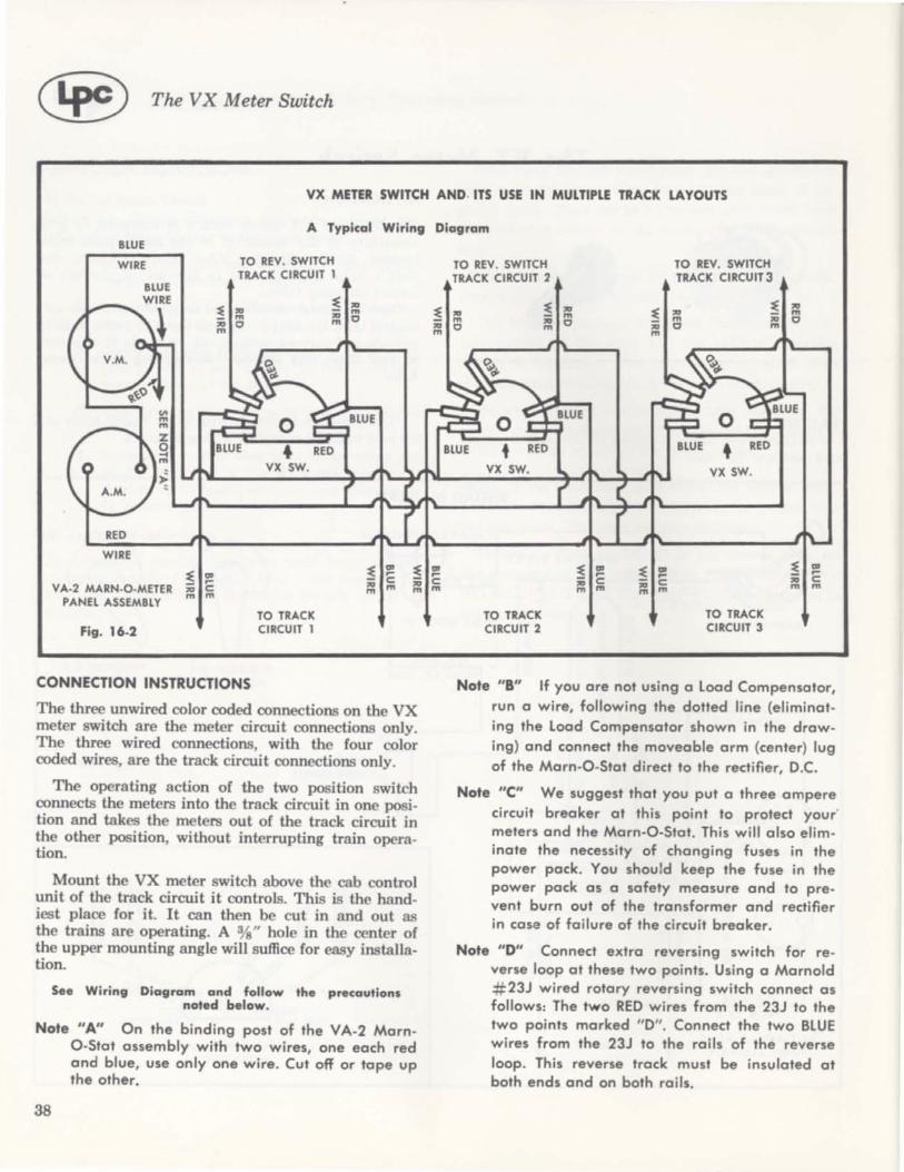
® The VX Meter Switch
VX METER SWITCH AND . ITS USE IN MULTIPLE TRACK LAYOUTS
A Typical Wiring Diagram BLUE
WIRE
RED
WIRE
VA·2 MARN·O·METER PANEL ASSEMBLY
Fig. 16.2
~ ~ '" C m m
TO REV. SWITCH TRACK CIRCUIT 1
~ ~ '" 0 m
VX SW.
TO TRACK CIRCUIT 1
~ '" '" m m 0
~ ~ '" C m m
CONNECTION INSTRUCTIONS
The three unwired color coded connections on the VX meter switch are the meter circuit connections only. The three wired connections, with the four color coded wires, are the track circuit connections only.
The operating action of the two position switch connects the meters into the track circuit in one position and takes the meters out of the track circuit in the other position, without interrupting train operation.
Mount the VX meter switch above the cab control unit of the track circuit it controls. This is the handiest place for it. It can then be cut in and out as the trains are operating. A %" hole in the center of the upper mounting angle will suffice for easy installation.
See Wiring Diagram and follow the precautions noted below.
Note "A" On the binding post of the VA-2 MarnO-Stat assembly with two wires, one each red and blue, use only one wire. Cut off or tape up the other.
38
TO REV. SWITCH TRACK CIRCUIT 2
VX SW.
TO TRACK CIRCUIT 2
~ ~ '" C m m
TO REV. SWITCH TRACK CIRCUIT 3
~ ~ '" 0 m
VX SW.
TO TRACK CIRCUIT 3
~ ~ '" 0 m
Note "B" If you are not using a load Compensator, run a wire, following the dotted line (eliminating the load Compensator shown in the drawing) and connect the moveable arm (center) lug of the Marn-O-Stat direct to the rectifier, D.C.
Note "c" We suggest that you put a three ampere circuit breaker at this point to protect your meters and the Marn-O-Stat. This will also eliminate the necessity of changing fuses in the power pack. You should keep the fuse in the power pack as a safety measure and to prevent burn out of the transformer and rectifier in case of failure of the circuit breaker.
Note "0" Connect extra reversing switch for reverse loop at these two points. Using a Marnold #23J wired rotary reversing switch connect as follows: The two RED wires from the 23J to the two points marked "0". Connect the two BLUE wires from the 23J to the rails of the reverse loop. This reverse track must be insulated at both ends and on both rails.

WIRING INSTRUCTIONS
Track Circuit
#1
#4
Connect the one RED wire from the VX meter switch to one BLUE wire from the reversing switch.
Connect the other RED wire from the VX meter switch to the other BLUE wire from the reversi ng switch.
Connect the one BLUE wire from the VX meter switch to one rail of the track.
Connect the other BLUE wire from the VX meter switch to the other rail of the track.
Meter Circuit
#5
#6
#7
Connect single BLUE wire from the VA-2 Marn-O-Meter assembly to the BLUE coded (unwired) connection of the VX meter switch.
Connect the single RED wire from the VA-2 Marn-O-Meter assembly to the RED coded (unwired) connection of the VX meter switch.
READ CAREFULLY. Conne!.t either the BLUE wire or the RED wire (one binding post on the VA-2 Marn-O-Meter assembly has both a RED and a BLUE wire leading
The VX Meter Switch C!§ from it}to the unwired connection of the VX METER SWITCH CODED WITH BLUE AND RED. Either cut off the unused wire or tape it up.
Now the VX meter switch is hooked up and ready to operate. In position # 1, the meters are out of the circuit. In position #2, the meters are in the circuit.
You can use the VA-2 Marn-O-Meter panel assembly to check voltage, current and train operation in any number of track circuits. Whether you have one, two, three or more track circuits and only one VA-2 assembly, by using a VX meter switch in each circuit, train operation can be easily checked in any one of the circuits by merely turning a switch. It's that easy. See Wiring Diagram illustrating three track circuits (Fig. 16-2) .
WARNING
When using two or more VX meter switches, only one at a time can be thrown to position #2, otherwise possible short circuits can occur resulting in blown fuses or even burned out or damaged power packs.
39

CHAPTER XVII
Paigelite High Frequency Lighting
PRINCIPLE OF HIGH FREQUENCY LIGHTING
Until the development of the Paigelite system, the model railroader experienced considerable difficulty with train lighting. The lamps run on the regular D.C. power, dim or brighten, as the train slows or gains speed. Batteries take up too much space in the cars and must be replaced often. The answer to the train lighting problem is the Paigelite High Frequency Lighting system.
The high frequency unit is mounted on a half panel to fit into the Marnold Ad-A-Panel framework.
The principle of the Paigelite system is that high frequency power used for lighting can pass through a capacitor or a condenser. These condensers prevent the D.C. power for running your train from entering the lamps.
The Paigelite panel contains a high frequency low voltage power source. All you do for a simple layout is to connect your Marnold power pack to the Paigelite panel which in turn is connected to the rails.
Fig . 17-1
The rails receive a mixture of D.C. running power and the high frequency power for lighting. The Paigelite is designed to operate 20 two-volt, 60 milliampere, grain of wheat, pea or miniature-based lamps.
In each car, mount a condenser to service the lamp and complete the circuit through the wheels to the track. The condenser will allow only the high frequency power to pass through the bulb and light it. The D.C. power is blocked by the condenser.
0.1 MFD. 2 VOLT, 60 MA LAMP
r ,t---~@ TO RAILS 1 Fig. 17-2
40
High Frequency Unit
THE INSTALLATION OF A CAPACITOR IN A COACH
If several lights are to be used in one car, you must have as many condensers of 0.1 mfd. each as there are lamps. A single condenser of equivalent size could also be used with connections as follows:
TO RAIL Fig. 17-5 TO RAIL
TO RAIL Fig . 17-6 TO RAIL
BUILDING YOUR OWN HIGH FREQUENCY SOURCE
For those who are interested in building their own high frequency source, the wiring diagram of the Paigelite panel high frequency source and a list of parts needed is also given.
NOTE: On account of the voltages involved, it is recommended that the beginner build the unit only under the direction and supervision of a person with experience in electronics.
When fewer than five lamps are used, connect a 10 ohm, 2 watt resistor across terminal 3 and 4.

PARTS LIST
Cat. Diagram No. Ref. No.
L#359P L
L#360P C1
L#361P C2
L#361P C3
L#362P C4
L#363P C5
L#364P R1
Operation of Paigelite with Single Pack and Block or Cab Controls
If your layout has many blocks, follow the wiring dia· gram below to make your connections. The Marnold throttle cab control panel used with your layout will need to be slightly modified when the Paigelite is used. One 4 mfd. 50 volt condenser must be connected
b.c. POWER PACK PAIGELITE
Paigelite High Frequency Lighting C!~
Cat. Diagram Description No. Ref. No. Description
No. 47 Pilot Lamp L#364P R2 2700 Ohm 1 Watt Resistor
1500 mfd. Mica L#365P R3 10 Ohm V2 Watt Condenser Resistor
5400 mfd. Mica L#93 11 Output Transformer Condenser
5400 mfd. Mica L# 104 T2 Filament Transformer Condenser 1·65A·6.3V
30 mfd. 15 Volt L#366P V1 Tube
Electrolytic Condenser
100 Mo. Selenium 4 mfd. 100 Volt (Paper) L#367F V2 Rectifier
Condenser
2700 Ohm 1 Watt L#95 S S.P.S.T. Switch Resistor
across the rheostat and load compensator of the throttle control panel.
The Marnold HO 30P, S 20P, 0 lOP Throttle Control Panels are all mounted on a half panel. The Throttle Control and the Paigelite Panel also on a half panel, can be mounted on a #550 Ad-A-Panel framework unit.
BLOCK 1
LOAD COMPENSAT~O . ._. _--r---IA A A. MARNOSTAT
~~...AA.A.A~ I I ,,;1 t vvv • +
Note the additional condensers marked C1 needed in the Marnold throttle cab control panel. These condensers must be 4 mId. 50 to 100 volt.
Fig. 17·8
CAPACITOR
~---------------------------+. -
BLOCK 2
LOAD COMPENSATOR
f\I'v t..fJ\M MARNOSTAT
~\~~~~C_I ______ ~ ____ ~. + CAPACITOR
L-____________________________ •• -
_"-_____________ TO ADDITIONAL BLOCKS
41

C® Paigelite High Frequency Lighting
MULTIPLE PACK OPERATION
For Multiple Pack Operation, the convenient commonrail system is necessary for the correct functioning of Paigelite. If you are not using the common rail system, it will be necessary to convert to it.
Follow the wiring diagram for your connections:
PAIGElITE PANel
Pack 1 ~ CAPACITOR
1
2
3
..
* CAPACITOR I I TO COMMON
Pack 2
RAIL RETURN OF EACH BLOCK
Pack 3 * CAPACITOR
Fig. 11·9
NOTE condensers added across the pack. The condensers should be 4 micro-farad, 50 to 100 volts.
High Frequency Lighting Power for Turnouts and Spurs
Since every layout either has or will have some turnouts, capacitors will be needed for the flow of high frequency power around the turnout. Otherwise, rolling stock sitting in the siding would be dark unless the turnout was set for it.
The following sketches show two turnout circuits. In the first circuit below:
CAPACITOR
CAPACITOR
Fig. 17·10
42
the D.C. path to either line is determined by the position of the turnout and thus requires two capacitors to keep the high frequency power on both branches at all times. The appropriate gap must be jumpered by the D.C. when the turnout is set in its direction. This can be done by means of the contacts on the turnout mechanism.
If only a spur is to be provided with the high frequency power, the simpler connections in the figure below are needed.
CAPACITOR
Fig. 17.11
The mainline is always powered by D.C. no matter which way the turnout is set. When the turnout is set for the spur, however, the D.C. also appears on it. In this position of the turnout, the spur must be jumpered by a contact on the turnout mechanism. High frequency power always appears on the spur.
SUPPLY OF CONDENSERS
The necessary condensers for isolating lamps (CPllOO) for jumpering turnouts as well as block and cab controls (CllOO) or (C4100) can be obtained from Scalite (948 North Keystone Avenue, Chicago 51, Illinois), or from the Leyghton-Paige Corporation, or from a radio parts dealer. Scalite also makes special car lighting kits designed for use with Paigelite. Use parts numbers when ordering.
The following condenser types will take care of all your layout needs.
Sea lite Number Description
Part No. CP1100 0.1 mfd., 100 volt capacitor for isolat-ing lamps in cars, locomotives, and cabooses.
Part No. C1100 1 mfd., 100 volt capacitor for jumper-ing sidings, cab controls are used where no more than 5 lamps need to be lighted in the jumpered block or siding.
Part No. C4100 " mfd., 100 volt capacitor for jumper. ing sidings, cab controls and used where up to 20 lamps may need to be lighted in the jumpered block or sid-ing.

Terminal Strip CHAPTER XVIII C!@
APPLICATION
This simple but important item helps you systematise your wiring and to connect more than one wire to a common terminal. The terminal strip provides an easily accessible point for checking voltages, currents and resistances when trouble shooting.
ASSEMBLY DIAGRAM
Show. th. #513 t.rminal .trip mounted on 1 #500 plu. 1 #550. Thr .. could b. mount· ed on thi., th. long .id • . Not. th. pr.·punch.d mounting hole. on the bolic framework . Two of th. #513 t.rminal .trip. can be mount.d on th •• hort .id • . Th. AD·A·PANEl d •• ign eliminat •• all wiring from the front and puts it in boc.k where wiring belongs. The •• t.rminal It rips make a much neat.r job of wiring, too.
Fig. 18.1
ASSEMBLY INSTRUCTIONS
o 0
Take the #513 Terminal Strip and place on your bench or table with the angle up as shown in the exploded assembly drawing. Then follow these steps in order.
No. 1. Take one binding post screw. No.2. Insert terminal lug or solder lug over screw. No.3. Insert one %" diameter fibre washer on top
of lug on the screw. No.4. Insert one 5/ 16" diameter fibre washer on
top of the %" washer on the screw. No. S. Insert the binding posts screw with the lug
and two washers into one of the 5 16" holes in the terminal strip #513, from the bottom side (with the angle up). Force the 5/ 16" diameter washer into the 5 / 16" hole in the terminal strip.
No.6. Insert the second %" diameter fibre washer. No.7. Insert the hex nut and screw all the way
down, making sure that the 5 16" fibre washer is still in the hole in the terminal strip. Tighten securely. Repeat the same procedure with all nine of the binding posts in the same direction. Then bend the lugs up away from the terminal strip.
o o o o o 0 0 ~ No. B. Then put on the nine knurled binding post
nuts. No.9. Mount to the Ad-A-Panel framework with
the two 6-32 screws and nuts. Mount with the angle away from the back of the framework.
PARTS FURNISHED
No. 1. 9 binding post screws No. 2. 9 solder or terminal lugs No. 3 . 9 %" fibre washers No. 4 . 9 5/ 16" fibre washers No. S. 1 #513 terminal strip No. 6. 9 %" fibre washers (same as #3) No. 7. 9 hexagon nuts No. B. 9 knurled nuts No. 9. 2 screws and nuts for mounting
terminal strips to back of Ad-A-Panel framework
43

MARNOLD DIVISION THE LEYGHTON-PAIGE CORP. SPRING PARK, MINNESOTA
PLACE STAMP HERE

Dat~e~ ________________ ___
Please send further Mamold information and instruction sheets that might become available at a later date.
NAM~E ________________________________________________ _
ADDRES·~S ______________________________________________ __
Cl" ________________________________________________ ___
lONE UAT~E ____________________________________ __

,