Embed Size (px)
Citation preview

MARLA Software for Planning Fuel Shuffles and Dry Cask Storage Campaigns
Dave Knott & Christian Oyarzun Studsvik Scandpower, Inc.
1015 Ashes Drive, Suite #205 Wilmington, NC 28405-8338
USA
ABSTRACT
MARLA is the Studsvik software product for the automated design and analysis of a fuel shuffle. The software also automatically chooses fuel bundles to be loaded into dry storage casks to provide space in the storage pools to meet future storage needs, and allows engineers to manage the spent fuel pool between outages. MARLA performs all tasks related to planning the fuel shuffle, including the optimisation of the fuel movement schedule, a complete shutdown margin analysis of every intermediate core configurations using the licensing-grade SIMULATE-3 advanced nodal code, and generation of the official fuel movement checklist used by the crane operators during core alterations. Shutdown margin analysis is interactive with the shuffle design and takes place during the planning stage - not after the sequence has been planned. This paper provides an overview of the various features of the software.

Knott and Oyarzun, MARLA
2
Contents
1. INTRODUCTION ......................................................................................................... 3 2. MARLA ......................................................................................................................... 3
2.1 The MARLA Graphics ....................................................................................... 4 2.2. The MARLA Computational Engine ................................................................ 5 2.3. The MARLA Project File Database ................................................................. 5 2.4. Coupling to SIMULATE-3 ............................................................................... 5
3. MAINTENANCE WORK ............................................................................................. 5 3.1. The MARLA Maintenance Core Panel ............................................................ 6 3.2. The MARLA Component Maintenance Panel .................................................. 6 3.3. Shuffle Phases .................................................................................................. 7
4. ARRANGING FUEL MOVES ...................................................................................... 8 5. SRM CONNECTIVITY ................................................................................................ 9 6. THE MARLA SHUTDOWN MARGIN CALCULATION ........................................ 10
6.1. Determining the Target Eigenvalue ............................................................... 10 6.2. Determining One-Rod-Out Reactivity ........................................................... 13
8. DECAY HEAT ANALYSIS ....................................................................................... 15 9. DRY CASK STORAGE CAMPAIGN PLANNING .................................................. 15 10. AUTOMATED POOL MANAGEMENT .................................................................. 16 11. FULL CORE OFFLOAD & RELOAD ...................................................................... 18 12. OUTPUT .................................................................................................................... 20 13. SURVEILLANCE MODE ......................................................................................... 23 14. SUMMARY ............................................................................................................... 24 ACKNOWLEDGEMENT ................................................................................................ 24 REFERENCES ................................................................................................................. 24

Knott and Oyarzun, MARLA
3
1. INTRODUCTION
At the end of a typical cycle of operation at a nuclear power plant, the reactor is shutdown, the containment pool is flooded, and the vessel head is removed to expose the reactor core inside. To transition the fuel in the core from its current configuration to the new configuration in preparation for the next cycle of operation, crews can use one of two approaches. The first approach is referred to as a "full core offload / reload" and consists of emptying the core entirely of all fuel bundles. Once the core has been emptied, maintenance work can take place within the core internals. This can include replacing control blades, replacing detector strings, performing weld inspections along the periphery of the reactor vessel, or performing plug inspections along the bottom of the vessel. Following completion of maintenance work, all fuel bundles are loaded back into the core in the new configuration and the vessel head is re-attached.
The second approach is referred to as a "fuel shuffle" and consists of keeping the
bulk of the fuel bundles within the core while moving them to their new core locations in preparation for the next cycle of operation. For this type of strategy, the shuffle is broken into two phases, where the first phase is used to remove fuel bundles from the core in order to open up “holes” that are needed to support the maintenance work, and the second phase is used to complete the fuel bundle relocation process. Depending on the size of the core and the type of containment building, the "fuel shuffle" strategy can reduce the length of the outage by as much as a week, relative to the time needed to perform a "full core offload / reload". For this reason, as well as others that will not be discussed here, the majority of Boiling Water Reactors, whose cores contain as many as 800 fuel bundles, routinely perform "fuel shuffles." The majority of Pressurised Water Reactors, whose cores typically contain fewer than 200 fuel assemblies, routinely perform "full core offloads / reloads".
If a "full core offload / reload" strategy is to be followed, there is no need to
analyse the fuel movements for shutdown margin (SDM) because the core is being directly loaded to its final configuration, which has been fully analysed for SDM during the reload licensing process. But if a "fuel shuffle" strategy is to be followed, there will exist hundreds of intermediate core configurations during the movement of fuel that have not been analysed for SDM. To comply with the requirements of the plant's Technical Specifications, each intermediate core configuration should be fully analysed for SDM prior to performing the fuel movement. It is the design and analysis of the "fuel shuffle" strategy that is the topic of this paper.
2. MARLA
MARLA [1] is a software package that is used to plan a very detailed fuel shuffle and automatically analyse all intermediate core configurations for shutdown margin. It is also used to manage site fuel storage pools and to plan dry storage cask campaigns that transfer older fuel bundles from the storage pool to special canisters located elsewhere on site. MARLA supports all containment designs, including GE Mark-III containments that include dual bridges and a fuel transfer tube between buildings (BWR/6, ABWR, and ESBWR plants). The MARLA software package consists of the following modules:

Knott and Oyarzun, MARLA
4
• A graphical user interface (GUI); • A computational engine; • SIMULATE-3 [2]; • An HDF5 database [3].
The interaction between the various modules is seamless to the user and is illustrated in Figure 1 and described briefly in the following sections.
GUI
Fuel Movement Checklist
HDF5 Database
S3 Nodal Code
Shuffle Engine
SDM instructions
Input from GUI
Shuffle Sequence
User constraints
Shuffle Sequence & SDM results
SDM results
Reports
Engineer
Figure 1. Relationship among MARLA software modules.
2.1 The MARLA Graphics
A graphical user interface (GUI) is used to enter maintenance work, select various design options, design manual fuel moves to complement the software’s automation, and view results from the shuffle strategy and SDM analysis. It consists of "panels", each of which contains a specific pool or rack (e.g., channel racks, control blade hangers, instrumentation drums, etc.). Each dry storage cask that is on site is also modelled on a separate panel. Drag-and-drop functionality allows designers to move components from one location to another within the core or any given pool, or from one pool to another. The manual moves are automatically recorded by the software and saved to the project file database.

Knott and Oyarzun, MARLA
5
2.2. The MARLA Computational Engine
The MARLA computational engine receives data from the graphical interface and automates the planning of the fuel moves. At the end of planning, it passes the information back to the graphics module. The computational engine controls the execution of all SIMULATE-3 SDM calculations and the calculation of decay heat for every fuel bundle on site (all fuel bundles in the core, in all pools, and in all dry storage casks). When planning a dry storage cask campaign, the engine is tasked with selecting fuel bundles to be loaded into the casks and decides how to re-arrange the spent fuel pools to meet US NRC B.5.b storage guidelines. These topics will be described in more detail in later sections of the paper.
2.3. The MARLA Project File Database
The MARLA project file is an HDF5 database that is used to facilitate communication between the graphical interface and the engine. The graphical interface populates the database with information from the user. When the user executes MARLA, the engine retrieves the data and performs the tasks requested. The engine places the results from the shuffle plan back into the database, where they are then retrieved by the graphical interface and presented to the user.
2.4. Coupling to SIMULATE-3
SIMULATE-3 is the Studsvik 3-dimensional, 2-group advanced nodal code for analysing steady state operation of Light Water Reactors. It performs the same tasks as nodal codes used by fuel vendors to license their reload designs. MARLA processes SIMULATE-3 restart files to gather information about the core and the fuel in the core. MARLA then controls execution of SIMULATE-3 to analyse intermediate core configurations for SDM.
3. MAINTENANCE WORK
MARLA allows the user to declare all maintenance work via a graphical panel, referred to as the Maintenance Core panel. Users can define activities such as:
• Control cells that need to be emptied to support blade replacement or drive
mechanism replacement. • Detector strings that need to be either replaced or inspected. • Non-discharge fuel bundles that need to be off-loaded for inspection or re-
channelling. • Fuel bundles that need to be sipped either prior to the shuffle or during fuel
movement.
Users may also specify core locations that are to be left open for a duration of the shuffle, or locations where fuel bundles are to remain fixed for a duration of the shuffle. An

Knott and Oyarzun, MARLA
6
example of the latter case would be locking two depleted fuel bundles in place around each source range monitor (SRM) during the shuffle to ensure adequate count rates.
3.1. The MARLA Maintenance Core Panel
The Maintenance Core panel is illustrated in Figure 2. An explanation of all the symbols on the panel is outside the scope of this paper. In general, the chartreuse squares represent the orientation of double blade guides that are to be inserted into cells that need to be emptied for blade maintenance. The red squares represent locations that need to be emptied in order to replace a detector string.
Figure 2. An example of the Maintenance Core panel.
3.2. The MARLA Component Maintenance Panel
MARLA also provides a second maintenance panel, referred to as the Component Maintenance panel, that allows the user to drag-and-drop any control blade or detector string between the core and the storage facility, as illustrated by the blue and grey panels in Figure 3. The instruction sheets for each replaced component are generated automatically for all the work defined on the panel.

Knott and Oyarzun, MARLA
7
Figure 3. An example of the Component Maintenance panel.
3.3. Shuffle Phases
Once all maintenance work has been specified, MARLA will split the shuffle design into two phases. The first phase shuffles the fuel from the beginning of the outage to the maintenance window. The second phase shuffles the fuel from the end of the maintenance window to the new reference loading pattern. All maintenance activities take place between phases.
Phase I of the shuffle can be automated as either a shuffle to the maintenance
window or a direct off-load of fuel bundles to open up all the necessary holes in the core. The choice is up to the user and is usually dictated by other outage considerations. Each phase of the shuffle can be automated as either a core-wide shuffle or a quadrant-by-quadrant shuffle. Quadrant-based shuffles can be beneficial in the event that the signal from an SRM is lost during the shuffle. In such cases, fuel cannot be moved in the quadrant until the SRM response returns and the quadrant-based shuffle design can potentially allow the plant to continue moving fuel in a different quadrant of the core without having to re-analyse for SDM while workers attend to the defective SRM. MARLA also allows users to rotate or re-define quadrant boundaries at any point during the shuffle. This is a tactic that is sometimes applied to small cores (e.g., 368 fuel bundles) in order to account for a defective SRM.
Knott and Oyarzun, MARLA
8
Alternatively, MARLA will allow the maintenance window to be broken into
multiple pieces and spread out over Phase I of the shuffle. This approach is used to support outages in Scandinavian countries, where maintenance work is often performed in stages during the shuffle. For instance, the user can instruct MARLA to shuffle for 1 day and then stop. The user can then perform a limited amount of maintenance work using the Component Maintenance panel, after which MARLA is instructed to continue the shuffle for another day and then stop again. This process continues until all maintenance work has been completed.
4. ARRANGING FUEL MOVES
Each fuel bundle move in MARLA is associated with a string, where a string is a cascade of moves beginning with the discharge of an exhausted fuel bundle and ending with the insertion of a fresh fuel bundle. That is, the first move in the string consists of discharging a fuel bundle from the core; the second move in the string consists of relocating a fuel bundle from its current location into the empty location created by the discharged fuel bundle; the third move in the string consists of relocating a fuel bundle from its current location to the empty location created by the second move in the string; and so on and so forth. The last move in the string consists of the insertion of a fresh fuel bundle into the empty location created by the preceding move in the string. MARLA begins each new string prior to completing the previous string. This helps minimise the number of empty crane moves in the shuffle. The discharged fuel bundle for string n+1 is moved to the pool and the fresh fuel bundle for the previous string, string n, is retrieved and carried back to the core to complete string n. Special attention has been devoted to GE BWR/6 and ABWR power plants in order to efficiently synchronise the refuelling floor bridge with the bridge in the fuel handling building and the inclined fuel transfer system that is used to pass fuel bundles between buildings.
MARLA uses a hierarchical approach to determine the order of strings to be
addressed during the shuffle. For the most part, strings are chosen that will minimise the number of empty crane moves and also minimise the distance the refuelling floor bridge must travel during the shuffle. In GE reactors, control blades will lean to one side if not supported by at least two diagonally adjacent fuel bundles. Under such conditions, the shuffle plan also focuses on choosing strings to avoid a potential rod lean configuration that would require additional moves to insert and remove blade guides. In ABB and KWU reactor designs, fine motion control blades are supported by a shaft and are incapable of leaning to one side. Under these conditions, MARLA will concentrate on choosing strings that will avoid placing highly reactive once-burnt fuel bundles face-adjacent to each other in the same control cell. This helps to avoid configurations that might fail SDM constraints, resulting in strings being broken.
In some instances, a string will contain neither a discharge nor an insertion, but
simply a rotation involving several fuel bundles. For these cases, MARLA will choose the best fuel bundle to be moved to a temporary set down location along the edge of the core and will perform the rotation of the remaining fuel bundles. The fuel bundle to be moved to the temporary set down location is chosen in such a way as to minimise the
Knott and Oyarzun, MARLA
9
distance the refuelling floor bridge travels to complete the rotation. If one of the fuel bundles in the rotation needs to be off-loaded for maintenance work, MARLA will choose that fuel bundle as the lead candidate in the string. At the end of the rotation, the fuel bundle which was initially sent to the temporary set down location will be rotated to its final destination. Alternatively, the engineer can choose not to allow temporary set down locations inside the core. In such instances, the lead fuel bundle will be moved to the storage pool, temporarily, until the rest of the fuel bundles in the string have been rotated.
5. SRM CONNECTIVITY
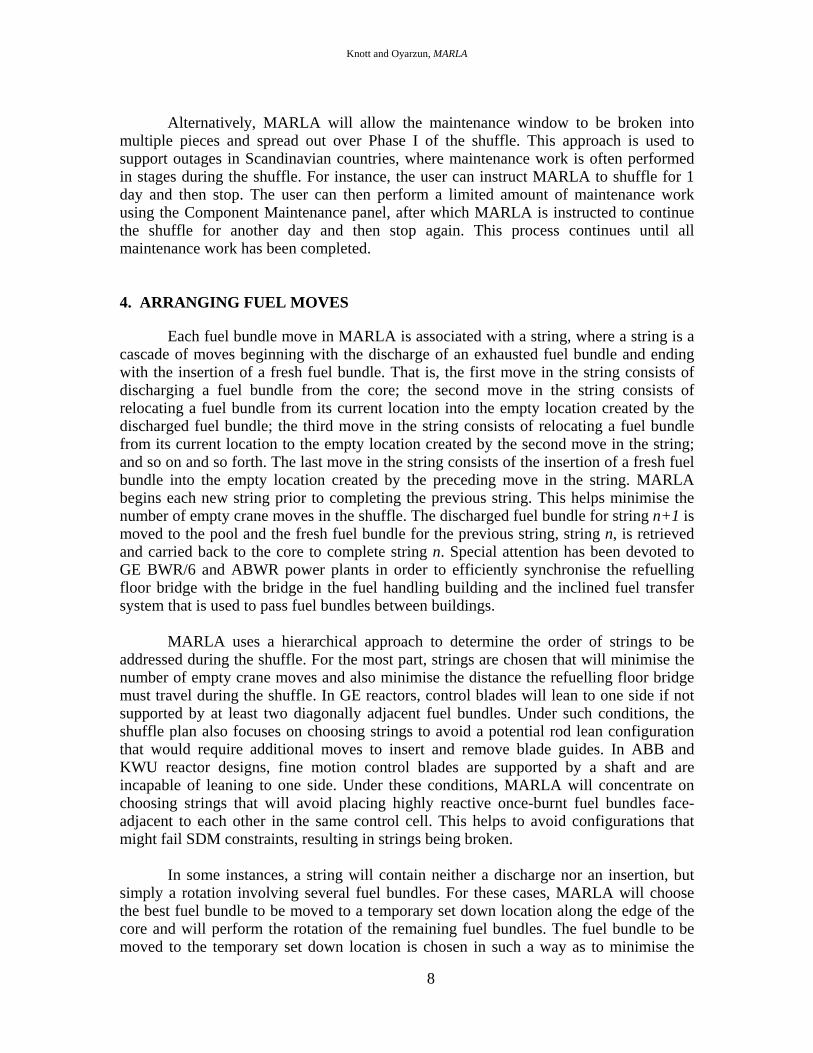
Source range monitors are used to monitor the core during core alterations. To satisfy Technical Specification requirements, there must be an unbroken path between each fuel bundle in the core and the appropriate SRM, as illustrated in Figure 4. The connectivity rule can be interpreted in different ways and MARLA accommodates various interpretations. In its most conservative interpretation, the unbroken path between each fuel bundle and the SRM can be made up of only face-adjacent fuel bundles. Less restrictive interpretations allow a limited number of diagonal paths and the user is able to specify the upper limit on the number of diagonal connections allowed within a single connectivity path.
Figure 4. SRM connectivity path.
MARLA contains two separate connectivity algorithms. The first algorithm uses a stencil between the fuel bundle location and the appropriate SRM and is extremely fast. The code searches for connectivity within the stencil. For the vast majority of moves,
SRM location Connection path

Knott and Oyarzun, MARLA
10
connectivity will be satisfied within the localised stencil, even for the most conservative interpretation of the rule. If the code fails to find a connection path within the stencil, MARLA then analyses the entire core in search of a connection path between the fuel bundle and the appropriate SRM. This path is allowed to move in all directions, so long as the appropriate rules are met. If MARLA fails to find a path that satisfies connectivity, the proposed shuffle step is revoked and the code searches for a different fuel move.
6. THE MARLA SHUTDOWN MARGIN CALCULATION
Shutdown margin represents the amount of reactivity that must be added to the core in order to reach a critical condition with the reactor in a cold shutdown state and all but the strongest control rod fully inserted. Since the location of the strongest rod changes with exposure, it is never known a priori and the calculation of shutdown margin requires that every rod in the core be withdrawn individually and assessed for margin. This type of analysis is referred to as a one-rod-out calculation, since it involves one rod in the core being fully withdrawn while all other rods in the core are fully inserted. The value of shutdown margin depends on the reactivity of the one-rod-out (ORO) calculation and the value of the target eigenvalue used to represent criticality in the nodal simulator code,
%100)( arg ×−= OROett kkSDM (1)
In Eq. (1), ettk arg is the target eigenvalue at cold conditions, and OROk is the
SIMULATE-3 one-rod-out reactivity. Most Tech Specs require plants to maintain 0.28% margin at all times if SDM is being verified through measurement (i.e.., isolated criticals), or 0.38% margin at all times if SDM is being verified through analysis. Traditionally, design calculations have used 1.0% margin as the minimum acceptable level in order to account for additional uncertainties associated with the target eigenvalue. This is the minimum amount of margin that is typically maintained during core alterations.
The calculation of shutdown margin is interactive in MARLA and is performed
while the code is searching for a shuffling sequence, as opposed to being performed following the design of a sequence. By default, shutdown margin is calculated for every proposed move that inserts a fuel bundle into the core. The user may also request SDM to be calculated for every proposed fuel bundle withdrawn from the core, but this is not necessary in order to satisfy reactivity management requirements.
6.1. Determining the Target Eigenvalue
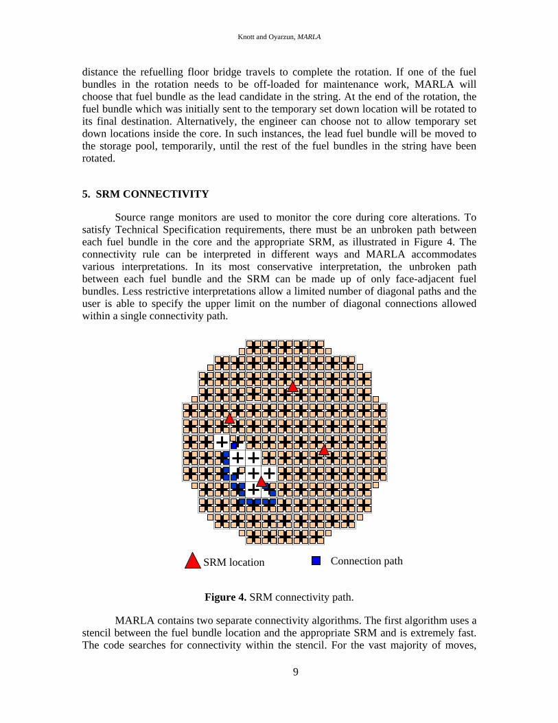
In a perfect world, the eigenvalue used to represent criticality in the nodal simulator code would be unity and there would be no need to determine a target eigenvalue. In practice, though, there is a bias in the critical reactivity as calculated by the nodal simulator code and the bias is often a strong function of exposure, as illustrated in Figure 5. That is, as the core ages, the critical eigenvalue changes. For the most part, such trends can be attributed to errors in the void coefficient and/or errors in the power-
Knott and Oyarzun, MARLA
11
to-void correlation. Over time, errors in the void fraction at the top of the core cause errors in the estimated isotopic concentrations in the upper portion of the fuel - most importantly in the concentration of the odd numbered Plutonium isotopes. At cold conditions, the fuel in the top of the core drives reactivity, so the eigenvalue calculated by the nodal simulator code is highly sensitive to such isotopic errors. The trend in critical eigenvalue makes it necessary to estimate a unique target eigenvalue for each step of the shuffle as the old fuel is discharged and fresh fuel is inserted (i.e., as the core-averaged exposure decreases).
0.988
0.989
0.990
0.991
0.992
0.993
0.994
0.995
0.996
0.997
12 14 16 18 20 22 24
Eige
nval
ue
Core-Averaged Exposure (GWd/ST)
EOC
BOC
Figure 5. Target eigenvalue versus core-averaged exposure.
To determine a target eigenvalue for a step, MARLA interpolates along a line connecting the SIMULATE-3 target eigenvalue at the beginning of the shuffle (i.e., at the end of the current cycle) to the SIMULATE-3 target eigenvalue at the end of the shuffle (i.e., at the beginning of the new cycle). This is illustrated by the red trend line in Figure 5. In the figure, the shuffle begins at the EOC point, when the fuel in the core is at its highest core-averaged exposure. As exhausted fuel is discharged and fresh fuel is inserted, the core-averaged exposure decreases and the shuffling plan works its way up the trend line toward the BOC point at the lowest core-averaged exposure.
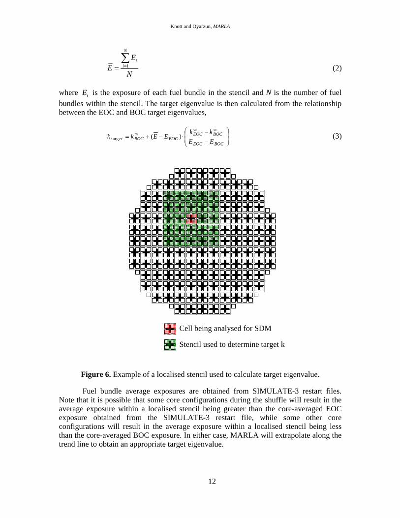
MARLA determines a target eigenvalue based on the specific core configuration
inside a localised stencil surrounding the control cell being analysed for SDM, as illustrated in Figure 6. The stencil is meant to represent the "field of influence" of the fuel bundle that has just been inserted into the core. For a specific core configuration, the average exposure in the localised stencil is calculated as,
Knott and Oyarzun, MARLA
12
1
N
ii
EE
N==∑
(2)
where iE is the exposure of each fuel bundle in the stencil and N is the number of fuel bundles within the stencil. The target eigenvalue is then calculated from the relationship between the EOC and BOC target eigenvalues,
⎟⎟⎠
⎞⎜⎜⎝
⎛
−−
⋅−+=∞∞
∞
BOCEOC
BOCEOCBOCBOCett EE
kkEEkk )(arg (3)
Figure 6. Example of a localised stencil used to calculate target eigenvalue.
Fuel bundle average exposures are obtained from SIMULATE-3 restart files. Note that it is possible that some core configurations during the shuffle will result in the average exposure within a localised stencil being greater than the core-averaged EOC exposure obtained from the SIMULATE-3 restart file, while some other core configurations will result in the average exposure within a localised stencil being less than the core-averaged BOC exposure. In either case, MARLA will extrapolate along the trend line to obtain an appropriate target eigenvalue.
Cell being analysed for SDM
Stencil used to determine target k

Knott and Oyarzun, MARLA
13
The size of the stencil is defined by the user. If a user wishes, the size of the stencil can be set to be equivalent to the entire size of the core. In this way, for a given shuffle step, the same target eigenvalue will be used for every cell in the core. This tends to produce a more conservative estimate of the target eigenvalue and is, therefore, often times a more practical choice for users. If the user specifies the same target eigenvalue for the beginning of the shuffle and the end of the shuffle, no interpolation will be performed and the stencil is not employed.
6.2. Determining One-Rod-Out Reactivity
The one-rod-out calculation is performed using the standard 3-dimensional, 2-group nodal solver in SIMULATE-3 and accounts for water holes explicitly. There are no special geometry or spectral approximations used for the one-rod-out analysis. To determine the control blades in the core that should be analysed for SDM for any particular shuffle step, MARLA will use an approach that spirals outward from the cell in which the fuel bundle has been inserted. The control blade in the cell of interest is withdrawn and the core reactivity is calculated. This reactivity is compared to the one-rod-out reactivity of the same cell prior to the fuel bundle insertion. If reactivity has increased by less than a user-specified threshold (250 pcm, for instance), the code assumes that the influence of the inserted fuel bundle is insignificant, stops analysing any more cells for SDM, and proceeds to determine the next fuel move in the shuffle sequence. If reactivity has increased beyond the threshold, MARLA expands the domain of the one-rod-out calculation to include the next nearest neighbouring cells, as illustrated by the sequence of stencils shown in Figure 7. Here, the red core location represents the inserted fuel bundle and the blue control cells represent the cells analysed for SDM as the stencil is expanded. The spiralling process continues until the reactivity increase in each of the cells in a ring falls below the threshold.
The one-rod-out analysis in MARLA is parallelised using OpenMP. Multiple
SIMULATE-3 jobs are submitted simultaneously to help reduce overall execution time. If the computer running MARLA contains a quad-core processor, for example, as many as four SIMULATE-3 one-rod-out cases can be submitted simultaneously. MARLA determines the number of cases to be submitted based on the number of cells in the ring of the core being analysed. Overall, the parallelisation routine can reduce execution time by an average factor of 2.5 on a quad-core processor compared to executing all SIMULATE-3 cases in series. On a duo quad-core processor (8 CPUs), the speed-up factor is closer to an average of 4. The speed-up factor fluctuates as more and more processors are added because it becomes uncommon for the stencil to grow large enough to make use of all processors simultaneously. For instance, in order to make use of 4 processors simultaneously, MARLA begins the one-rod-out analysis with a stencil size of 2x2. This allows all 4 processors to be utilised simultaneously for the first 4 one-rod-out cases (equalling the same amount of wall clock time it would take to perform a single one-rod-out calculation in series). If the stencil needs to grow to a size of 3x3, the next 4 one-rod-out calculations (cases 5 through 8) can be analysed simultaneously, but the last calculation (case 9) must be analysed separately. For such a situation, it requires 3 cycles of analysis to complete 9 one-rod-out calculations, which translates to a speed-up factor of 3. In order to make use of 8 processors simultaneously, the stencil must grow from a size of 2x2 to at least 5x5, which happens infrequently. If 16 processors are available,

Knott and Oyarzun, MARLA
14
MARLA begins the one-rod-out analysis with a stencil size of 4x4 and expands it if needed. This tends to be highly efficient because a stencil size of 4x4 is usually sufficient for the majority of fuel moves.
Figure 7. Spiralling approach to SDM.
If a proposed move violates the minimum acceptable amount of margin, the move is revoked and MARLA searches for a different fuel move. This can only be done because of the interactive nature of the SDM calculation, which takes place as the shuffle steps are being proposed. If MARLA waited until after the shuffle was designed to analyse each step for SDM, other - more inefficient - means would need to be found to account for potential SDM violations.
The total number of SIMULATE-3 one-rod-out calculations needed to fully
analyse a shuffle depends on the size of the core and the batch size, plus the threshold specified by the user to decide if a cell is influenced by an inserted fuel bundle. In
(a) (b)
(c) (d)

Knott and Oyarzun, MARLA
15
general, though, the number of SIMULATE-3 one-rod-out calculations ranges from 6,000 for small cores to 10,000 for large cores.
8. DECAY HEAT ANALYSIS
Decay heat loads are calculated for all fuel bundles in the MARLA model, at all times during the shuffle design when a fuel bundle is being moved between different pools or between the core and a pool. The code gathers all the data needed to perform the decay heat calculation from a series of SIMULATE-3 restart files that represent the operating history of the plant. Given a shutdown date and time, and a date and time that represents the onset of fuel movement, MARLA uses a simple internal clock to calculate the time at which each fuel bundle is expected to be moved between pools.
MARLA uses one of two internal methods to calculate decay heat loads for each
fuel bundle on site. The ANSI/ANS standard [4] is used to calculate decay heat for cooling times of less than 1 year. Under such conditions, latent heat is primarily caused by the decay of the short lived fission products and the ANSI/ANS standard models this heat in adequate detail. For cooling times in excess of 1 year, such as those important for planning dry storage cask loading campaigns, latent heat is caused by the decay of fission products plus the decay of the excited actinides and MARLA will use US NRC Regulatory Guide 3.54 [5] to determine the total heat load generated by the fuel bundle.
9. DRY CASK STORAGE CAMPAIGN PLANNING
MARLA determines the fuel bundles that should be loaded into dry storage casks in order to clear space in the pools to accommodate future storage needs. MARLA accepts a series of future dates on which casks will be loaded and finds fuel bundles in the storage pool that meet target heat loads and any cask-specific constraints. There is an internal library of cask designs from which the user can choose. MARLA can plan the loading of fuel bundles into casks well into the future in order to ensure that the plant will be able to fully load all casks safely without violating heat load limits. The Fuel Movement Checklist necessary to move the fuel bundles from the pool to the casks is generated automatically following the analysis.
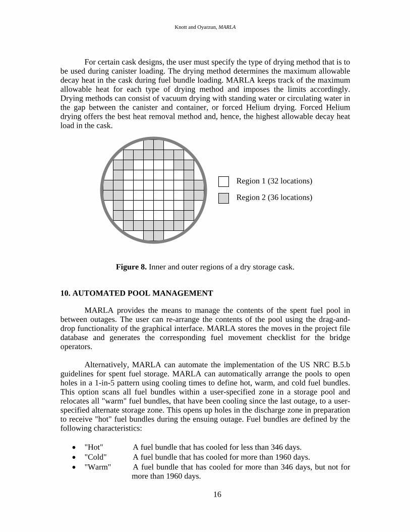
MARLA allows the user to define an inner-region-to-outer-region heat load ratio
for each cask. In this way, the user can fine-tune cask loadings to suit any desired outcome. Figure 8 contains a schematic of a typical dry cask canister that can accommodate 68 BWR fuel bundles. The definition of the inner region locations and the outer region locations is contained in the vendor's Certificate of Compliance, submitted to the US NRC. For this particular design, the canister contains 32 inner region locations and 36 outer region locations. By adjusting the ratio, users can allow hotter fuel bundles to occupy the inner region of the canister and cooler fuel bundles to occupy the outer region of the canister, thereby minimising the radiation level on the outside of the cask and minimising the dose received by plant personnel. MARLA will automatically search through all fuel bundles in storage and find the best candidates to load into each region of the canister.
Knott and Oyarzun, MARLA
16
For certain cask designs, the user must specify the type of drying method that is to
be used during canister loading. The drying method determines the maximum allowable decay heat in the cask during fuel bundle loading. MARLA keeps track of the maximum allowable heat for each type of drying method and imposes the limits accordingly. Drying methods can consist of vacuum drying with standing water or circulating water in the gap between the canister and container, or forced Helium drying. Forced Helium drying offers the best heat removal method and, hence, the highest allowable decay heat load in the cask.
Figure 8. Inner and outer regions of a dry storage cask.
10. AUTOMATED POOL MANAGEMENT
MARLA provides the means to manage the contents of the spent fuel pool in between outages. The user can re-arrange the contents of the pool using the drag-and-drop functionality of the graphical interface. MARLA stores the moves in the project file database and generates the corresponding fuel movement checklist for the bridge operators.
Alternatively, MARLA can automate the implementation of the US NRC B.5.b
guidelines for spent fuel storage. MARLA can automatically arrange the pools to open holes in a 1-in-5 pattern using cooling times to define hot, warm, and cold fuel bundles. This option scans all fuel bundles within a user-specified zone in a storage pool and relocates all "warm" fuel bundles, that have been cooling since the last outage, to a user-specified alternate storage zone. This opens up holes in the discharge zone in preparation to receive "hot" fuel bundles during the ensuing outage. Fuel bundles are defined by the following characteristics:
• "Hot" A fuel bundle that has cooled for less than 346 days. • "Cold" A fuel bundle that has cooled for more than 1960 days. • "Warm" A fuel bundle that has cooled for more than 346 days, but not for
more than 1960 days.
Region 1 (32 locations)
Region 2 (36 locations)
Knott and Oyarzun, MARLA
17
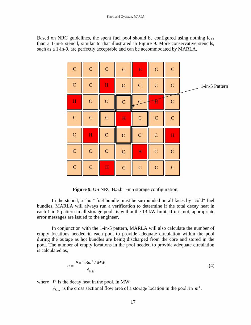
Based on NRC guidelines, the spent fuel pool should be configured using nothing less than a 1-in-5 stencil, similar to that illustrated in Figure 9. More conservative stencils, such as a 1-in-9, are perfectly acceptable and can be accommodated by MARLA.
Figure 9. US NRC B.5.b 1-in5 storage configuration.
In the stencil, a "hot" fuel bundle must be surrounded on all faces by "cold" fuel
bundles. MARLA will always run a verification to determine if the total decay heat in each 1-in-5 pattern in all storage pools is within the 13 kW limit. If it is not, appropriate error messages are issued to the engineer.
In conjunction with the 1-in-5 pattern, MARLA will also calculate the number of
empty locations needed in each pool to provide adequate circulation within the pool during the outage as hot bundles are being discharged from the core and stored in the pool. The number of empty locations in the pool needed to provide adequate circulation is calculated as,
21.3 /
hole
P m MWnA
×= (4)
where P is the decay heat in the pool, in MW.
holeA is the cross sectional flow area of a storage location in the pool, in 2m .
C C H C C C C
C C C C H C C
C H C C C C H
C C C H C C C
H C C C C H C
C C H C C C C
C C C C H C C
1-in-5 Pattern

Knott and Oyarzun, MARLA
18
And the value of 1.3 m2 / MW is the NRC recommended flow area per MW of decay heat being generated in the pool.
By default, MARLA will calculate the decay heat load in each pool, P, using a cooling time of 60 days after reactor shutdown. The user can adjust this time estimate to a different value, if desired. The user is also free to adjust the flow area per MW value.
11. FULL CORE OFFLOAD & RELOAD
MARLA can automate the design of a full core offload from any point in a shuffle, in addition to automating the design of a full core offload from the beginning of an outage. Full core offloads can be designed using a full complement of double blade guides or a partial complement. If the full core offload is to use a partial complement of double blade guides, MARLA automates the movement of blade guides from one cell in the core to another and automates messages to the Fuel Movement Checklist to instruct control room operators to remove control blades prior to the blade guides being removed from the cell.
For full core offloads, MARLA will split the core radially into 4 zones and will
design the offload / reload phases using a different quadrant-based strategy in each zone. In most cases, the code will order quadrants to be emptied and reloaded in a way that minimises the number of fuel bundles that are carried over the core. This minimises the chance of debris falling out the bottom of the fuel bundle being moved and into the top of a fuel bundle below. The definition of the four radial zones is illustrated in Figure 10. zone 4 is made up of fuel bundles used to connect the SRMs. Zone 1 includes all fuel bundles on the outside of zone 4. Zone 3 contains all fuel bundles on the inside of zone 4. And zone 2 includes all fuel bundles bridging the SRMs in the SW and SE quadrant of the core. MARLA will off-load the core in the following radial order: zone 1; zone 2; zone 3; zone 4. It will reload the core in the reverse radial order: zone 4; zone 3; zone 2; zone 1.
By default, MARLA will empty the core quadrants per zone in the following
order:
• Zone 4: SE, SW, NW, NE. • Zone 3: SE, (then SW if applicable). • Zone 2: SE, NE, NW, SW. • Zone 1: SE, NE, NW, SW.
This ordering minimises fuel bundle carryover while providing sufficient SRM connectivity. MARLA will reload the core quadrants in the reverse order with one caveat – the four fuel bundles surrounding each SRM will be loaded into the core first, prior to any other fuel being loaded. MARLA will always load depleted fuel bundles around SRMs before loading any fresh fuel. This helps to ensure an adequate count rate from each SRM prior to loading any other fuel into the core.

Knott and Oyarzun, MARLA
19
Figure 10. Zone definitions for a full core offload.
Users are allowed to re-define quadrant boundaries to run in between control cells
as opposed to running through the middle of control cells. This allows MARLA to off-load or reload an entire control cell of fuel bundles along each major axes while in a particular quadrant, rather than having to split the cell up into different quadrants.
By default, double blade guides will be oriented in a SW-NE direction. Blade
guides that surround an SRM are oriented in such a way that allows the four fuel bundles surrounding the SRM to remain in the core until the very end of the offload. The default
SRM location
Zone 1
Zone 2
Zone 4
Zone 3
Knott and Oyarzun, MARLA
20
orientations are overridden by any blade guide specified via the Maintenance Core panel. If a blade guide orientation surrounding an SRM is overridden by the user, MARLA will automatically re-orient the guide prior to reloading the core. This ensures that all four fuel bundles surrounding each SRM can be loaded immediately following maintenance work.
12. OUTPUT
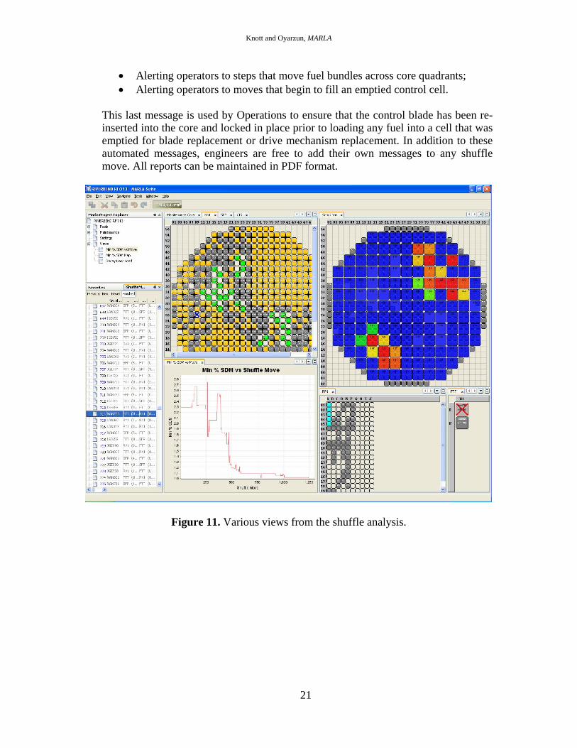
Output from MARLA is in the form of a step-by-step animation of fuel moves, printed fuel movement checklists for the bridge operators, step-by-step SDM results, and step-by-step decay heat loads in the core and in all pools. All data is stored in the MARLA project file database and is viewable from the graphical user interface that drives the software. Users may step through the shuffle in as much detail as desired. Engineers may manually manipulate moves generated by the automated shuffle design to better suite the needs of the outage management team. If the sequence is manually manipulated by the user, the modifications are automatically re-analysed for SDM. Figures 11 through 13 contain examples of various views from the MARLA results.
Figure 12 contains results of total heat load in each pool (including the core) as a function of time after shutdown. The heat load in the core (RX1) decreases as depleted fuel bundles are removed during Phase I, some of which are sent to the Fuel Prep Pool (FPP) for inspection or re-channelling, some of which are sent to the Spent Fuel Pool (SFP) for final storage, and some of which are sent to the upstairs Reactor Pool (RP1) for temporary storage. While this transfer of fuel bundles is taking place, the heat load in each of the receiving pools is increasing. The long, fairly constant region between 230 and 330 hours is the maintenance window, during which time no fuel movement is taking place (i.e., fuel bundles are cooling in place). Phase II begins at 330 hours and consists of all the temporarily discharged fuel being sent from the RP1 and FPP pools back to the core. Whatever discharges are left in the core are sent to the SFP. At the very end of the shuffle, a dozen or so fuel bundles are transferred from the FPP to the SFP.
MARLA will also estimate the time needed to complete the fuel shuffle. Timings are supplied by the user and represent the various types of bridge moves that take place during the shuffle. The shuffle efficiency is optimised by minimising the number of empty crane moves and also by judiciously choosing locations in the fuel pool that minimise the distance the refuelling floor bridge travels.
Several different types of reports are generated automatically by MARLA. These include: a summary of different types of bridge moves and an estimate of the total time needed to complete core alterations; an estimate of the time that each fuel bundle is available for inspection or re-channelling; the fuel movement checklist, which is used by Operations to carry out the shuffle; a summary of the physical and isotopic characteristics of fuel bundles chosen to be loaded into dry storage casks; a listing of messages issued by the software during the shuffle design; etc. The fuel movement checklist contains several different types of messages that are automatically generated by MARLA, such as:
• Alerting operators to the SRM that is responsible for each move;
Knott and Oyarzun, MARLA
21
• Alerting operators to steps that move fuel bundles across core quadrants; • Alerting operators to moves that begin to fill an emptied control cell.
This last message is used by Operations to ensure that the control blade has been re-inserted into the core and locked in place prior to loading any fuel into a cell that was emptied for blade replacement or drive mechanism replacement. In addition to these automated messages, engineers are free to add their own messages to any shuffle move. All reports can be maintained in PDF format.
Figure 11. Various views from the shuffle analysis.

Knott and Oyarzun, MARLA
22
Figure 12. Total decay heat load in each pool as a function of shuffle step.
Knott and Oyarzun, MARLA
23
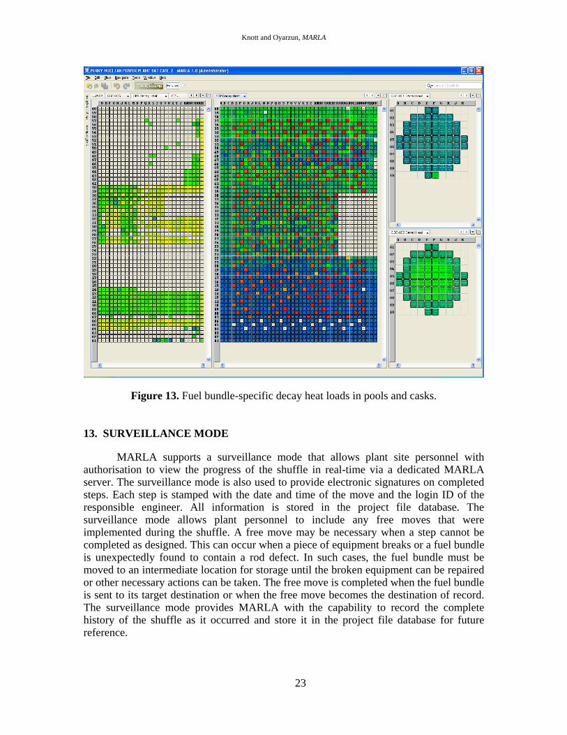
Figure 13. Fuel bundle-specific decay heat loads in pools and casks.
13. SURVEILLANCE MODE
MARLA supports a surveillance mode that allows plant site personnel with authorisation to view the progress of the shuffle in real-time via a dedicated MARLA server. The surveillance mode is also used to provide electronic signatures on completed steps. Each step is stamped with the date and time of the move and the login ID of the responsible engineer. All information is stored in the project file database. The surveillance mode allows plant personnel to include any free moves that were implemented during the shuffle. A free move may be necessary when a step cannot be completed as designed. This can occur when a piece of equipment breaks or a fuel bundle is unexpectedly found to contain a rod defect. In such cases, the fuel bundle must be moved to an intermediate location for storage until the broken equipment can be repaired or other necessary actions can be taken. The free move is completed when the fuel bundle is sent to its target destination or when the free move becomes the destination of record. The surveillance mode provides MARLA with the capability to record the complete history of the shuffle as it occurred and store it in the project file database for future reference.

Knott and Oyarzun, MARLA
24
14. SUMMARY
MARLA automatically designs and analyses all aspects of a fuel shuffle. Every move of a shuffle is fully analysed for shutdown margin using the licensing-grade 3-dimensional, 2-group advanced nodal code SIMULATE-3. The package allows for complete maintenance of all nuclear components and pools on site, including control blades, channels, detector strings, and neutron sources. Run times are kept reasonable by submitting multiple SIMULATE-3 cases simultaneously and by implementing a dynamic SDM algorithm that chooses cells for one-rod-out analysis on an as-needed basis. Overall run-times are dependent on the size of the core being analysed and the machine being used. For application on a Windows-based quad-core desktop, execution times range from 60 minutes for small BWR cores (<500 fuel bundles) to 100 minutes for large BWR cores (~800 fuel bundles).
MARLA is also capable of fully planning a dry cask storage campaign at the push
of a button. The software automatically calculates decay heat loads for every fuel bundle on site, on any given future date, and automatically selects fuel bundles for placement in each cask. Vendor-specific loading constraints for each type of cask are contained in an internal library and MARLA automatically selects fuel bundles that meet all constraints. At the end of the run, MARLA generates the fuel movement checklist needed by the crane operators to move fuel from the pool to each cask and generates the loading reports needed by administrators.
ACKNOWLEDGEMENT
Many, many thanks to Marla S.
REFERENCES
1. D. Knott, "MARLA Software Design Description," SSP-09/420, Studsvik Scandpower, Inc., May 2009.
2. L. Covington, "SIMULATE-3 Advanced Three-Dimensional Two-Group Reactor Analysis Code, User's Manual," SSP-01/414, rev. 3, Studsvik Scandpower, Inc., May 2003.
3. HDF Group, 2007. HDF5 User's Guide, release 1.8.0.
4. “American National Standard for Decay Heat Power in Light Water Reactors,” ANSI/ANS-5.1-2005, American Nuclear Society, April 2005.
5. Regulatory Guide 3.54, "Spent Fuel Heat Generation in an Independent Spent Fuel Storage Installation," Rev. 1, U.S. Nuclear Regulatory Commission, January 1999.