Embed Size (px)
Citation preview

Speedtronic® Mark V Turbine Control System
BHEL HYDERABADBHEL HYDERABAD

Speedtronic Control SystemSpeedtronic Control System

What is a Mark V Control
• Dedicated Turbine Control system.• Part of the Speedtronic family of controllers• Microprocessor based • Redundant electronic Protection systems • PC based interface.• <BOI>
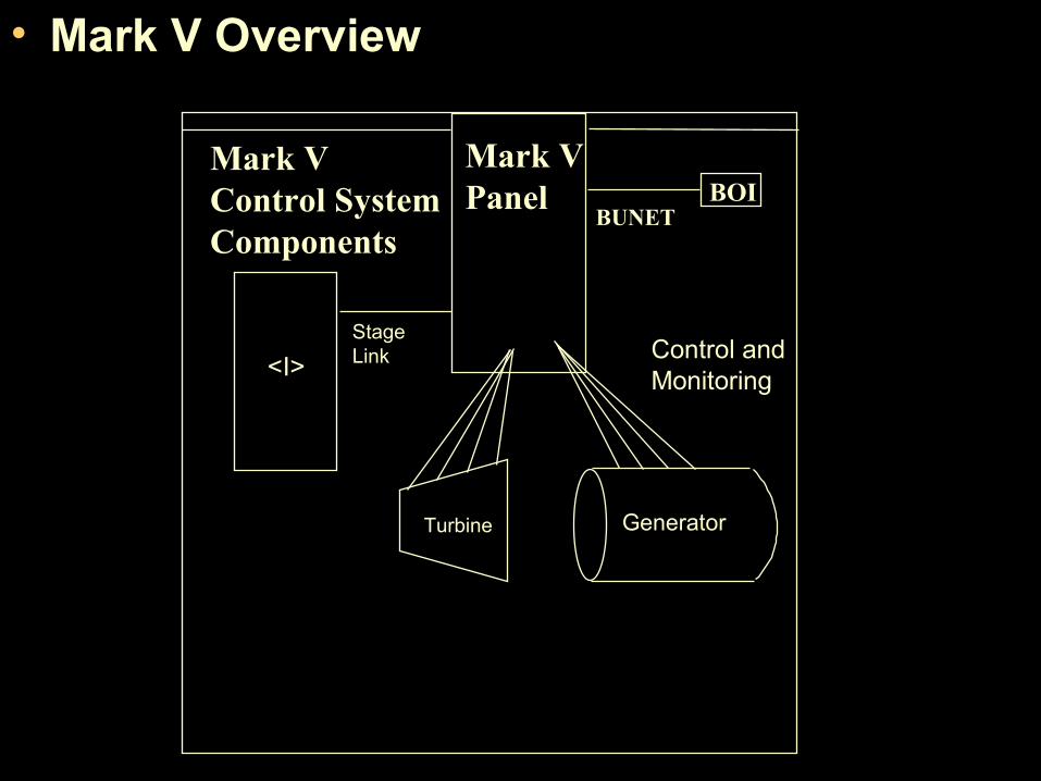
• Mark V Overview
Mark VPanel BOI
BUNET
Mark VControl SystemComponents
StageLink
Turbine Generator
Control andMonitoring<I>

TMR CONFIGURATION
<R>
Mark VTMR PanelCoresLayout
<S> <C>
<T> <P>
<QD1> <CD>
<PD>
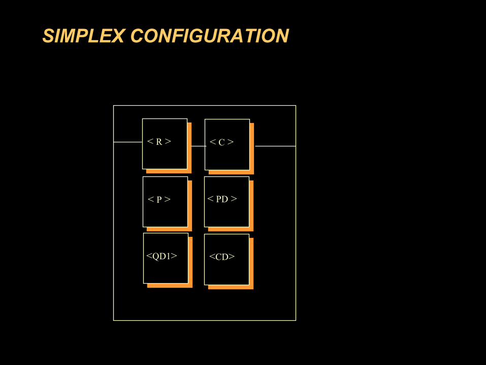
SIMPLEX CONFIGURATION
< R > < C >
< P > < PD >
<QD1> <CD>
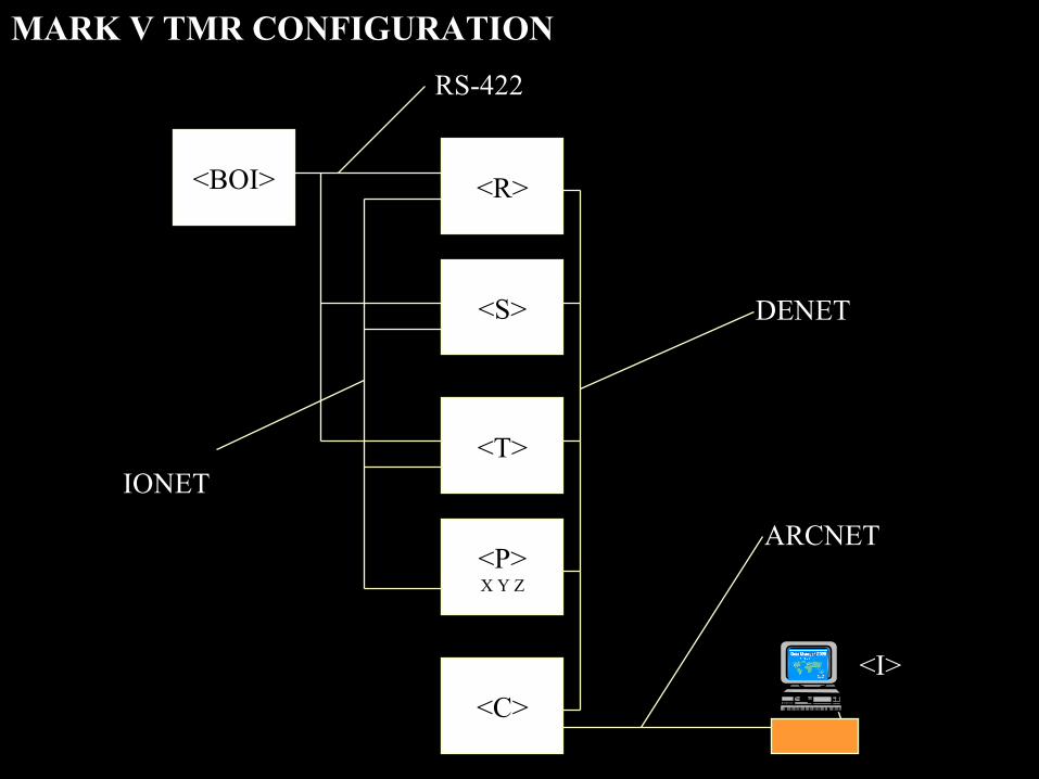
<R>
<S>
<T>
<C>
<BOI>
<P>X Y Z
RS-422R>
DENET
ARCNET
IONET>
<I>
MARK V TMR CONFIGURATION
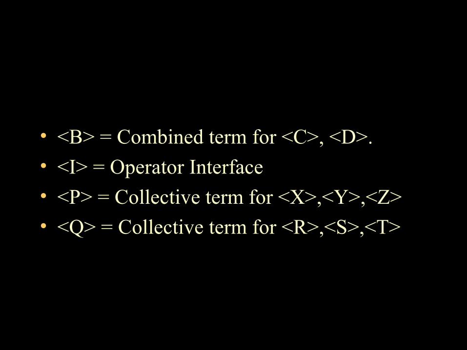
• <B> = Combined term for <C>, <D>.
• <I> = Operator Interface
• <P> = Collective term for <X>,<Y>,<Z>
• <Q> = Collective term for <R>,<S>,<T>
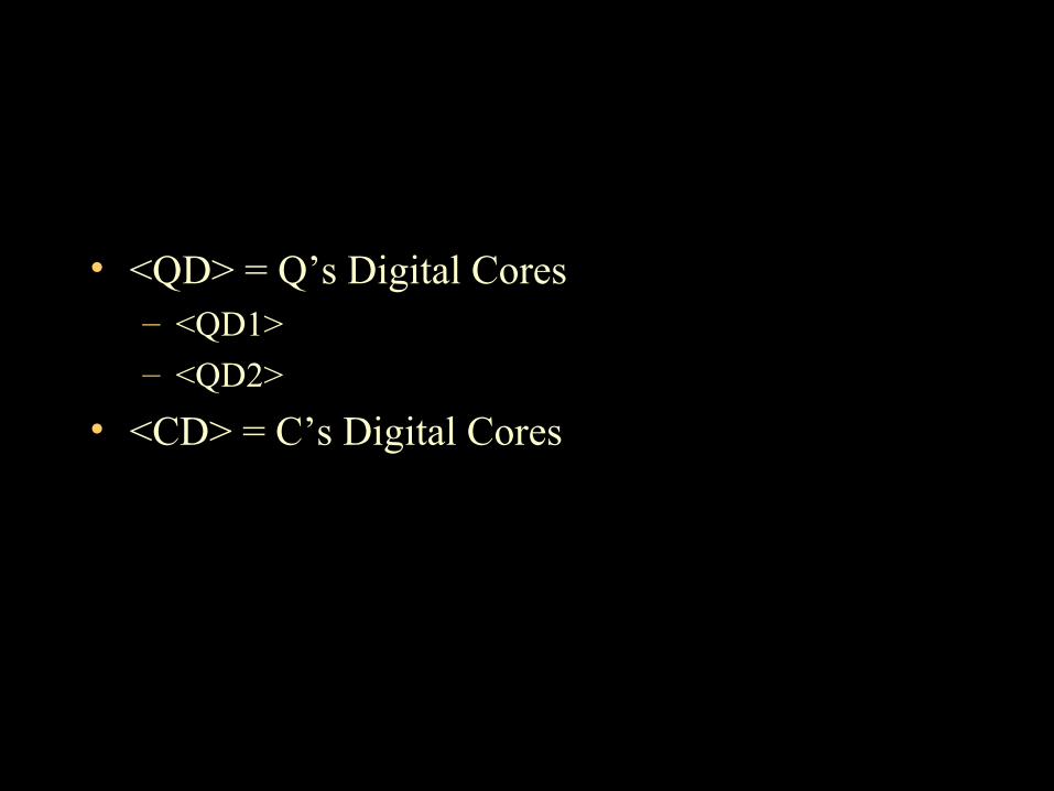
• <QD> = Q’s Digital Cores– <QD1>– <QD2>
• <CD> = C’s Digital Cores
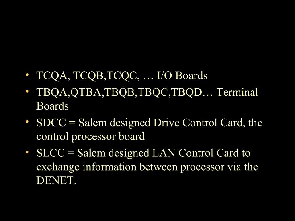
• TCQA, TCQB,TCQC, … I/O Boards• TBQA,QTBA,TBQB,TBQC,TBQD… Terminal
Boards• SDCC = Salem designed Drive Control Card, the
control processor board • SLCC = Salem designed LAN Control Card to
exchange information between processor via the DENET.

What’s in a name • TC xx Turbine Control
– EA Emergency(<P>) Core A Version
– DA Digital Core(<QD>,<CD>)
– Q A-D Q cores, I/O Boards, different versions
– C A-C C Core, I/O Boards, different versions
– TG, L,S P Core, Trip Board
• x TB x Terminal Board– C A <C> Core, A Version
– Q A <Q> Core, A Version
– P A <P> Core, A Version
– D A Digital cores, a version
• TB xx Turbine Board– C A-C <C> Core, A,B,C versions
– Q A-D <Q> Core, A,B,C,D versions

Mark V Overview
Mark V Panel
Communication <C> and / or <D> Control <R>, <S>, <T> Protection <P> Digital inputs / Outputs <CD>, <QDn> Power Distribution <PD> Extended I/O Cores - LM only -- “<S>“
Cores and Boards
Cores
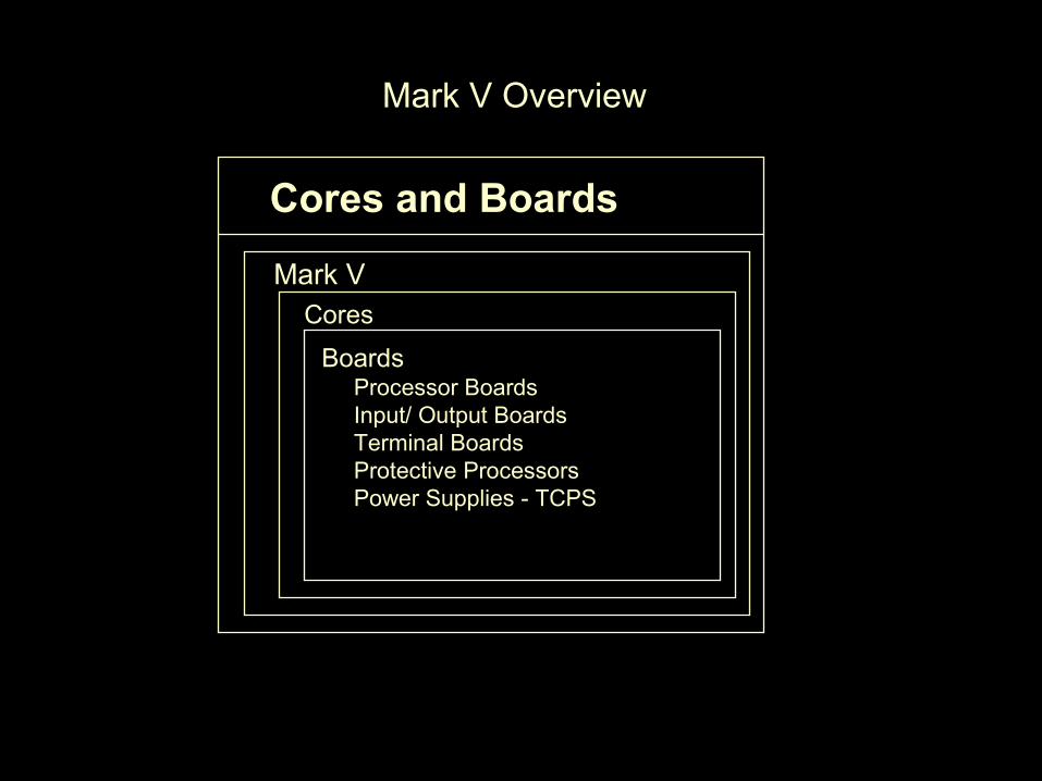
Mark V Overview
Cores and Boards
Mark VCores
Boards Processor Boards Input/ Output Boards Terminal Boards Protective Processors Power Supplies - TCPS

• Mark V Overview
Mark V Control Panel Boards
Location 2Location 3
Location 4Location 5
Location 1
Location 6
Location 7
Location 8
Location 9
Back
Bottom
Front
Top

•I/O Terminal Boards• I/O Boards• Processor Boards - Drive Control Cards SDCC or DCC - LAN Control Cards SLCC or LCC• Protective Processors - <X>, <Y>, <Z>• Power Supply Boards• Power Distribution Board
Mark V Boards

I/O Terminal Boards
• Few Active components
• Hardwire jumper configuration
• I/o device direct termination

I/O Boards
• Functions• Converts “real world” signals to/from digital signal for the processors• Scale and condition I/O signals• Servo Valve output regulation
• I/O configuration software• I/O configuration constants• Hardware jumper configuration.
Processor Boards
• (S)DCC Drive Control Cards - Location 1 <C>, <D>, and <Q> Processors - Executes the Control Sequence Program for each` Processor• (S)LCC - LAN Control Cards - Transfer Digital information between Processors - Passes data to <C>‘s SLCC, then to <I> - Does the voting in TMR applications
Protective Processors
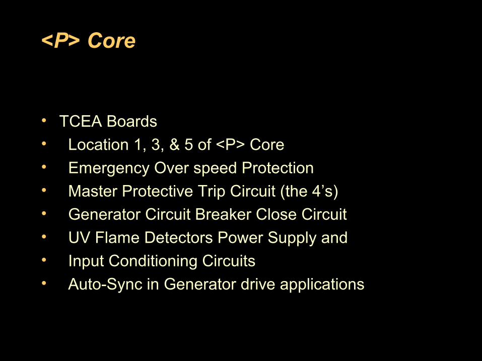
• TCEA Boards• Location 1, 3 & 5 of <P> Core• Emergency Over speed Protection• Master Protective Trip Circuit (the 4’s)• Generator Circuit Breaker Close Circuit• UV Flame Detectors Power Supply and Input Conditioning Circuits• Auto-Sync in Generator drive applications
• TCPS• Location 5 <C>, <D> and <Q> Processors• Powers DCCs and I/O Boards
• Input: 125 VDC• Outputs:
– - +/- 24 VDC
– - +/- 15 VD– - +/- 5 VDC
Power Supply Boards
Power Distribution Board
• TCPD Board• Located in <PD> core• Distributes 125 Vdc to:
– - Power Supply Boards for <C>, <D>, <Q> Core– - Protective Processors – - PLU Processors – - <QDn> and <CD> cores for solenoid outputs
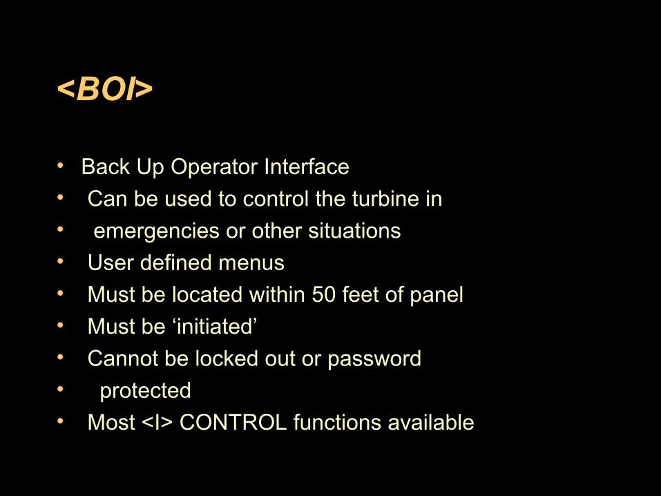
<BOI>
• Back Up Operator Interface• Can be used to control the turbine in• emergencies or other situations• User defined menus• Must be located within 50 feet of panel
• Must be ‘initiated’• Cannot be locked out or password• protected• Most <I> CONTROL functions available
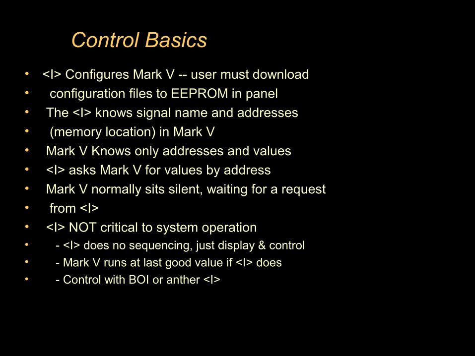
Control Basics
• <I> Configures Mark V -- user must download• configuration files to EEPROM in panel• The <I> knows signal name and addresses• (memory location) in Mark V• Mark V Knows only addresses and values• <I> asks Mark V for values by address• Mark V normally sits silent, waiting for a request• from <I>• <I> NOT critical to system operation• - <I> does no sequencing, just display & control• - Mark V runs at last good value if <I> does• - Control with BOI or anther <I>
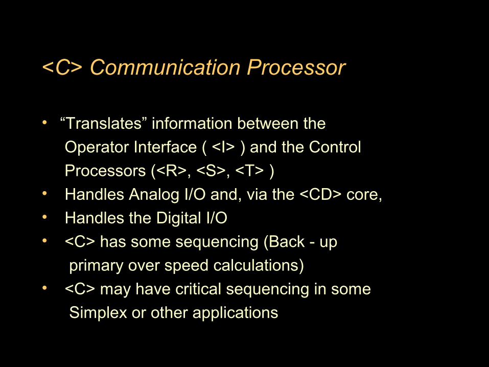
<C> Communication Processor
• “Translates” information between the
Operator Interface ( <I> ) and the Control
Processors (<R>, <S>, <T> )• Handles Analog I/O and, via the <CD> core,• Handles the Digital I/O
• <C> has some sequencing (Back - up
primary over speed calculations)• <C> may have critical sequencing in some
Simplex or other applications
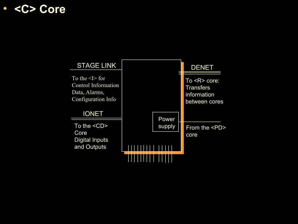
• <C> Core
IONET
To the <CD> CoreDigital Inputsand Outputs
Powersupply
DENET
To <R> core:Transfersinformationbetween cores
From the <PD>core
STAGE LINK
To the <I> forControl InformationData, Alarms, Configuration Info

<R>, <S>, <T> Cores
• Control Processors• Use the CSP to do:• - Critical Control Sequencing• - Primary Protection Sequencing
• SIFT and Vote the data• Critical Analog I/O
• Sync Check for Generator Drive Turbines
• Communicate with their components in • <QDn>, <PLU>, <P> Cores

• <R>, <S>, <T> Cores
IONET
To the <QD> and<P> CoresDigital Inputsand Outputs
Powersupply
Field wiring, in and out analog signals
DENET
To other corestransfersinformationbetween cores
125 V DC Power
From the <PD>core

<CD> Core
• Communication Processor Digital I/O Core• 96 Not “critical” Contact Inputs• 60 Not “critical” Contact outputs

<QDn> Core
• Control Processor’s Digital I/O Core
• <Q>‘s Digital I/O
• 96 Critical Contact Inputs• 60 Critical Contact outputs
<P> Core
• TCEA Boards• Location 1, 3, & 5 of <P> Core• Emergency Over speed Protection• Master Protective Trip Circuit (the 4’s)• Generator Circuit Breaker Close Circuit
• UV Flame Detectors Power Supply and• Input Conditioning Circuits• Auto-Sync in Generator drive applications

ADVANTAGES OF MARK-V OVER MARK-IV
• MARK-V HARDWARE HAS BEEN BUILT WITH STATE OF THE ART TECHNOLOGY AND 16 BIT MICROPROCESSOR.
• PROTECTION FUNCTION BEING EXTREMELY CRITICAL IS REALISED IN INDEPENDENT TMR<P> CONTROLLER.
• OPERATOR INTERFACE IS EASIER AS IT IS THROUGH A PC BASED <I> STATION WITH 19”
• VGA COLOUR GRAPHIC CRT, 101 FUNCTION ASCII KEYBOARD AND TRACKBALL. THE
• MARK-V PANEL IS LOCATED AS A SEPARATE FREE STANDING PANEL AND THE <I>
• STATION IS PLACED ON TABLE TOP AT A CONVENIENT LOCATION AWAY FROM THE

ADVANTAGES OF MARK-V OVER MARK-IV
• PANEL. AS A BACK UP TO THE <I> STATION, A SOFT KEY TYPE BACK UP OPERATOR. INTERFACE IS MOUNTED ON THE PANEL FRONT DOOR TO PERFORM CRITICAL FUNCTIONS.
• SYSTEM IS FAULT TOLERANT, ACHIEVED THROUGH SIFT (SOFTWARE IMPLEMENTED FAULT TOLERANCE), THEREBY REDUCING THE LIKELYHOOD OF SPURIOUS TRIPS AND GREATLY ENHANCING THE SYSTEM AVAILABILITY.
• ALL INTER-CORE CONNECTIONS ARE THROUGH FLAT CABLE. THIS AGAIN INCREASES THE SYSTEM AVAILABILITY AS IT ELIMINATES POSSIBILITY OF WIRE BREAKAGE AND LOOSE TERMINATION THAT IS GENERALLY ASSOCIATED WITH DISCREET WIRING.
• CONNECTIVITY TO EXTERNAL SYSTEMS IS IMPROVED AS IT IS THROUGH MODBUS LINK.
• THE SYSTEM IS MORE COMPACT THEREBY REDUCING THE DIMENSION OF PANEL.
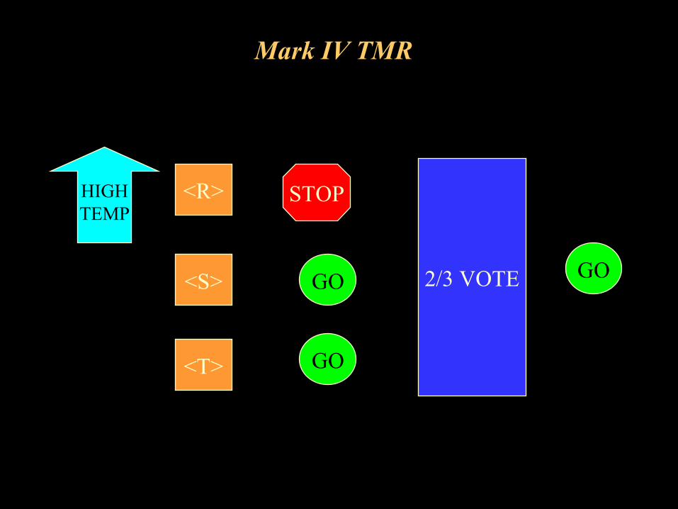
Mark IV TMR
<R>
<S>
<T>
STOP
GO
GO
2/3 VOTE GO
HIGHTEMP
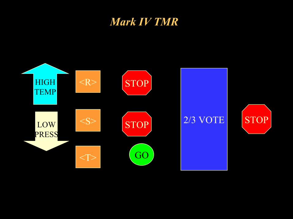
Mark IV TMR
<R>
<S>
<T>
STOP
GO
2/3 VOTE
HIGHTEMP
LOWPRESS
STOP STOP
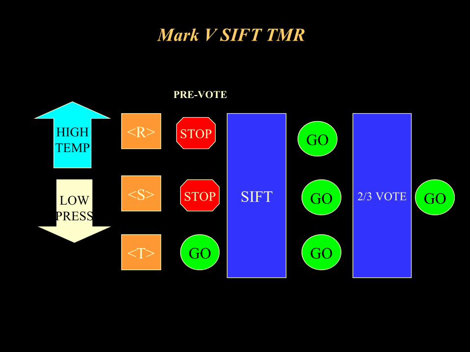
Mark V SIFT TMR
PRE-VOTE
<R>
<S>
<T>
2/3 VOTE
HIGHTEMP
LOWPRESS
GOSTOP SIFT
GO
GO
GO
STOP
GO
MarkV Control Documents
• Control Sequence program and cross reference
• I/O report
• Hardware report
• Alarm list
• MODBUS List
![Frame 6B pre-owned Equipment listControl system [--] Speedtronic MarkV (was MarkIV, upgraded in 2000) Design temperature inlet air exhaust air [°C] [°C] 15 540 ÷ 550 after installation](https://img.pdfslide.us/doc/110x75/5e7f52230696e422ad7b2751/frame-6b-pre-owned-equipment-list-control-system-speedtronic-markv-was-markiv.jpg)