Embed Size (px)
Citation preview
CHAPTER 5
MARKSMANSHIP TRAINING
The procedures, exercises, and techniques for implementing aproper marksmanship program are based on the concept thatall machine gunners must understand common firingprinciples, be proficient marksmen, and be confident inapplying these skills in combat. This depends on theirunderstanding of the machine gun and their application ofmarksmanship fundamentals. Proficiency is accomplishedthrough practice that is supervised by qualified trainers andthrough objective performance amassments by the unit leaders.The structure of this chapter is in four sections: planning,fundamentals, basic marksmanship, and advanced gunnery.All advanced exercises are conducted under conditions thatare as much like tactical conditions as possible.(See Appendix B for training aids and devices.)
Section I. PLANNING
The planning of MG training is no different from other marksmanshiptraining. Guidelines are provided to assist the trainers in understanding,preparing, and ensuring that all training is conducted to standard. Thissection addresses the objectives, the responsibilities of the commanders,and the phases of training. It also introduces the training devices that assistin training, and designates when remedial and sustainment training shouldbe conducted.
5-1. OBJECTIVESThe objectives of the MG training program are to guide the trainers,leaders, and gunners through a sequence of training to standard thatproduces a gunner who is able to maintain the gun and effectively engagetargets in combat.
5-2. COMMANDER’S RESPONSIBILITIESThe responsibilities of the commander are to ensure the instructors andtheir assistants are thoroughly trained and rehearsed in the planning,knowledge, and presentation of all MG training. He will ensure that safetyis emphasized and never overlooked during training. Serviceable weapons
5-1
FM 23-65
are a must for good training and commanders must make sure they areused properly. He also ensures sufficient time is scheduled.
5-3. PHASES OF TRAININGThe initial training strategy is divided into three phases of marksmanshipinstruction — the fundamental phase, the basic marksmanship phase, andthe advanced gunner phase. Gunner safety is continuously stressed duringall phases of training.
a. In the fundamental phase, the gunner learns the necessary commonskills, such as dry-fire exercises, preparation of positions, manipulation ofthe T&E, range determination, and sighting and aiming. The gunner mustmaster these skills before he is allowed to progress to the basicmarksmanship phase.
b. During the basic marksmanship phase, the gunner learns the basicsof loading, zeroing, laying, and engaging of single and multiple targetsfrom the tripod and vehicle mode.
c. The advanced gunnery phase trains the gunner in engaging movingtargets, night firing, NBC firing, mounted firing, and firing using firecommands. The gunner will be placed under the stress and strain ofsimulated combat conditions.
5-4. SUSTAINMENT TRAININGOnce individuals and units have trained to a required level of proficiency,leaders must structure collective and individual training plans to conductcritical task training at the frequency necessary for the sustainmenttraining strategy. Mission training plans and individual training evaluationprograms help achieve and sustain collective/individual proficiency.Sustainment training prevents skill degradation. Army units must beprepared to accomplish their wartime missions at any time – they cannotrely on infrequent peaking to the appropriate level.
5-5. REMEDIAL TRAININGRemedial training will be conducted in any of the phases of training wherethe gunner does not meet the standard. The trainer must be instantlyaware of any gunner that seems to be having trouble. Once the problemhas been identified, the gunner should be retrained as soon as possible sothat he will maintain the same level of proficiency as the other gunners.
5-2

FM 23-65
Section II. FUNDAMENTALS
The fundamentals are necessary basic skills that a gunner must be trainedin before he can be expected to effectively engage targets. Personnelconducting marksmanship training must fu l ly unders tand thefundamentals and be well rehearsed in applying them. The basics in MGtraining are assuming a proper firing position, sighting, aiming,determining range, and manipulating the T&E mechanism.
5-6. FIRING POSITIONSBefore a gunner can hit targets, he must learn to get behind the weapon ina position that allows him to be comfortable, affords him protection, andenhances mission accomplishment.
a. The tripod firing positions are prone, sitting, and standing. They areassumed in the following manner.
(1) The prone position is used when firing from the tripod that is setin a low position. It is assumed by lying on the ground directly behind thegun. The gunner then spreads his legs a comfortable distance apart withhis toes turned outward. His left elbow rests on the ground, and his lefthand grasps the elevating handwheel of the T&E. His right hand lightlygrasps the right spade grip with his right thumb in a position to press thetrigger. The position of his body can then be adjusted to position his firingeye in alignment with the sights of the weapon (Figure 5-1).
Figure 5-1. Prone position with tripod mount.
(2) The sitting position can be used when the tripod is set in a high orlow position. The gunner sits directly behind the gun between the legs ofthe tripod. He may extend his legs under the tripod or cross them,depending on his physique. The gunner then places both elbows on theinside of his thighs to get the best support. He grasps the elevating
5-3
FM 23-65
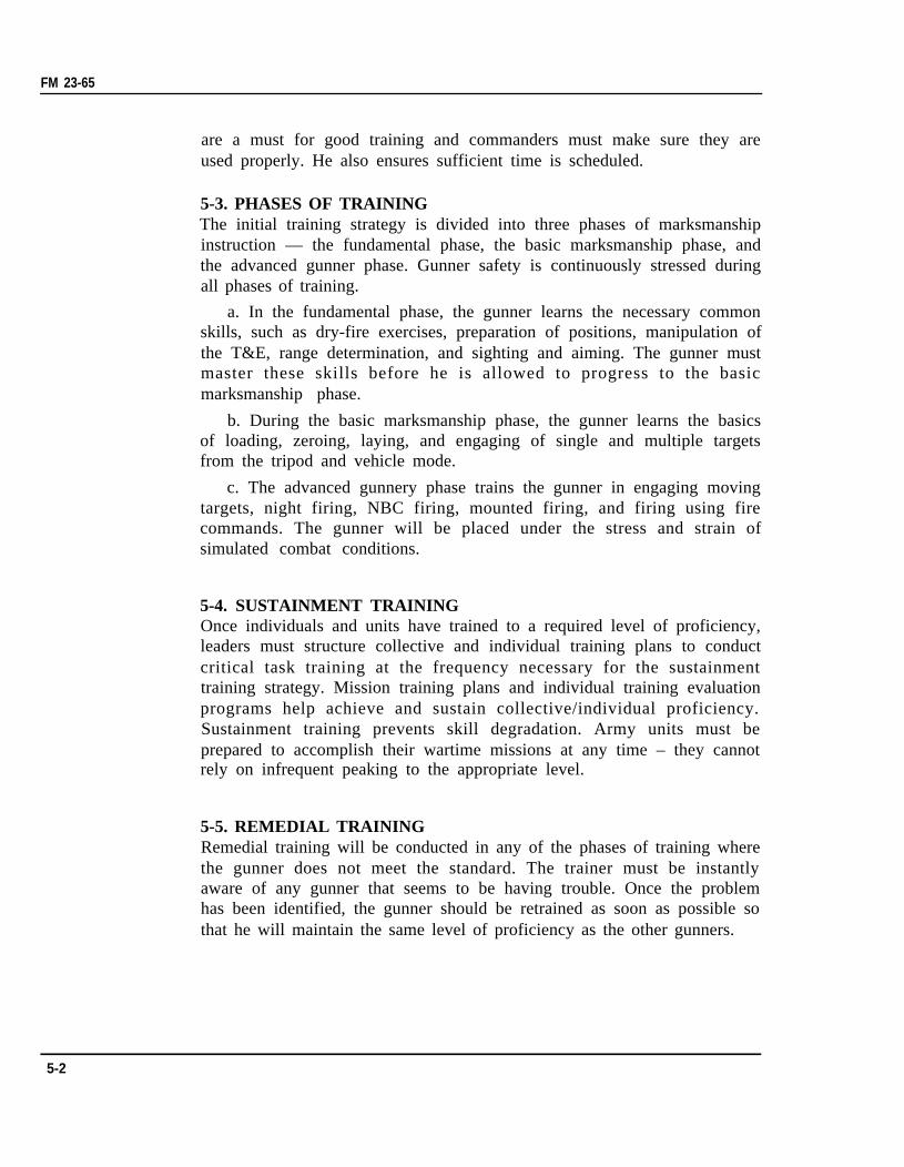
handwheel of the T&E with the left hand, and lightly grasps the rightspade grip with his right hand. He must ensure that the right thumb is inposition to press the trigger (Figure 5-2).
Figure 5-2. Sitting position with tripod mount.
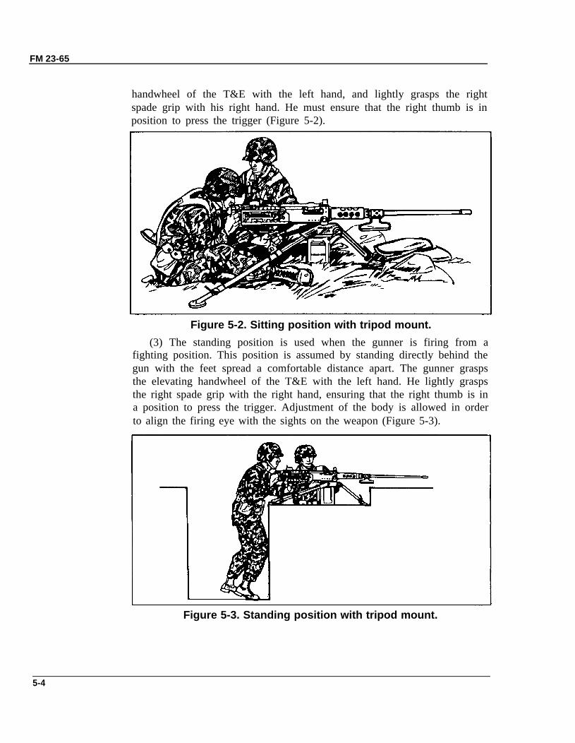
(3) The standing position is used when the gunner is firing from afighting position. This position is assumed by standing directly behind thegun with the feet spread a comfortable distance apart. The gunner graspsthe elevating handwheel of the T&E with the left hand. He lightly graspsthe right spade grip with the right hand, ensuring that the right thumb is ina position to press the trigger. Adjustment of the body is allowed in orderto align the firing eye with the sights on the weapon (Figure 5-3).
Figure 5-3. Standing position with tripod mount.
5-4
FM 23-65
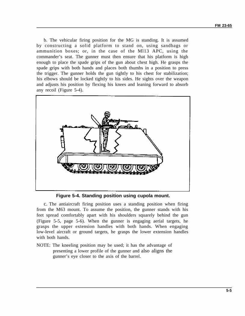
b. The vehicular firing position for the MG is standing. It is assumedby constructing a solid platform to stand on, using sandbags orammunition boxes; or, in the case of the Ml13 APC, using thecommander’s seat. The gunner must then ensure that his platform is highenough to place the spade grips of the gun about chest high. He grasps thespade grips with both hands and places both thumbs in a position to pressthe trigger. The gunner holds the gun tightly to his chest for stabilization;his elbows should be locked tightly to his sides. He sights over the weaponand adjusts his position by flexing his knees and leaning forward to absorbany recoil (Figure 5-4).
Figure 5-4. Standing position using cupola mount.
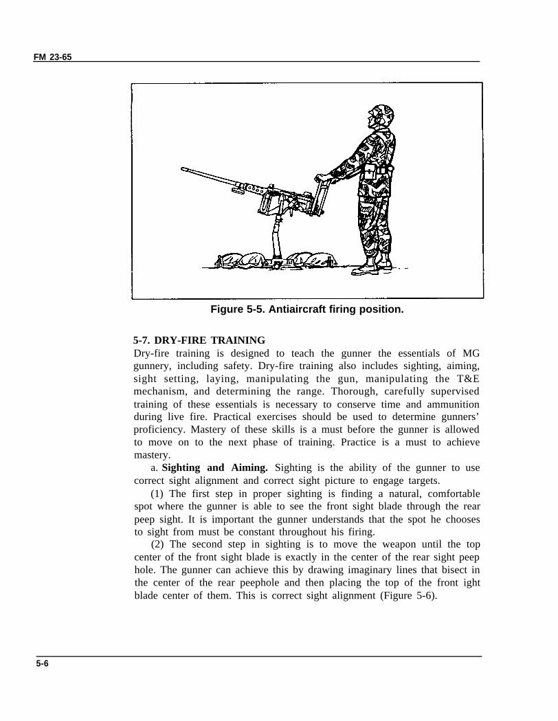
c. The antiaircraft firing position uses a standing position when firingfrom the M63 mount. To assume the position, the gunner stands with hisfeet spread comfortably apart with his shoulders squarely behind the gun(Figure 5-5, page 5-6). When the gunner is engaging aerial targets, hegrasps the upper extension handles with both hands. When engaginglow-level aircraft or ground targets, he grasps the lower extension handleswith both hands.
NOTE: The kneeling position may be used; it has the advantage ofpresenting a lower profile of the gunner and also aligns thegunner’s eye closer to the axis of the barrel.
5-5
FM 23-65
Figure 5-5. Antiaircraft firing position.
5-7. DRY-FIRE TRAININGDry-fire training is designed to teach the gunner the essentials of MGgunnery, including safety. Dry-fire training also includes sighting, aiming,sight setting, laying, manipulating the gun, manipulating the T&Emechanism, and determining the range. Thorough, carefully supervisedtraining of these essentials is necessary to conserve time and ammunitionduring live fire. Practical exercises should be used to determine gunners’proficiency. Mastery of these skills is a must before the gunner is allowedto move on to the next phase of training. Practice is a must to achievemastery.
a. Sighting and Aiming. Sighting is the ability of the gunner to usecorrect sight alignment and correct sight picture to engage targets.
(1) The first step in proper sighting is finding a natural, comfortablespot where the gunner is able to see the front sight blade through the rearpeep sight. It is important the gunner understands that the spot he choosesto sight from must be constant throughout his firing.
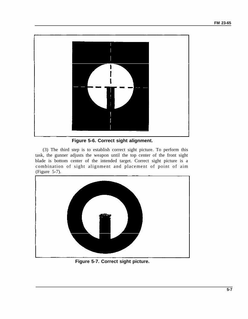
(2) The second step in sighting is to move the weapon until the topcenter of the front sight blade is exactly in the center of the rear sight peephole. The gunner can achieve this by drawing imaginary lines that bisect inthe center of the rear peephole and then placing the top of the front ightblade center of them. This is correct sight alignment (Figure 5-6).
5-6
FM 23-65
Figure 5-6. Correct sight alignment.
(3) The third step is to establish correct sight picture. To perform thistask, the gunner adjusts the weapon until the top center of the front sightblade is bottom center of the intended target. Correct sight picture is acombination of sight alignment and placement of point of aim(Figure 5-7).
Figure 5-7. Correct sight picture.
5-7
FM 23-65
b. Range Setting and Laying. Range setting and laying the gun areimportant elements in marksmanship training. It is this training thatprepares the gunner to accurately and rapidly place fire on his target incombat. To properly set ranges, the gunner must be trained in rear sightoperation.
(1) Setting ranges on the rear sight is a simple but important task. Thegunner just has to rotate the elevating screw knob in a clockwise mannerto move the peep sight up or counterclockwise to move it down. The rangescale on the left is graduated in mils and the scale on the right in yards.The gunner must align the hairline index of the peep sight with the scaleindex line at the desired range as quickly and accurately as possible.
(2) Laying is placing the barrel of the weapon on a direct line with thetarget, using the sights. This must also be done as quickly and accurately aspossible.
(3) The range setting and laying exercises are designed to require thegunner to practice and the instructor to evaluate both correct sightalignments and correct placements of aiming points. The exercise startswith the gunner in the sitting firing position with rear sight down. Thecoach will announce a range and general aiming point. The gunner willthen repeat the range and direction of target. The coach will thenannounce, “Begin.” The gunner will then raise and set his sights, and alignthe weapon on the aim point. When the gunner completes this task, he willannounce “Up.” The coach will then get behind the weapon and check therange setting and aim point and critique the gunner on his findings. Thisexercise will be continued until speed and accuracy is obtained.
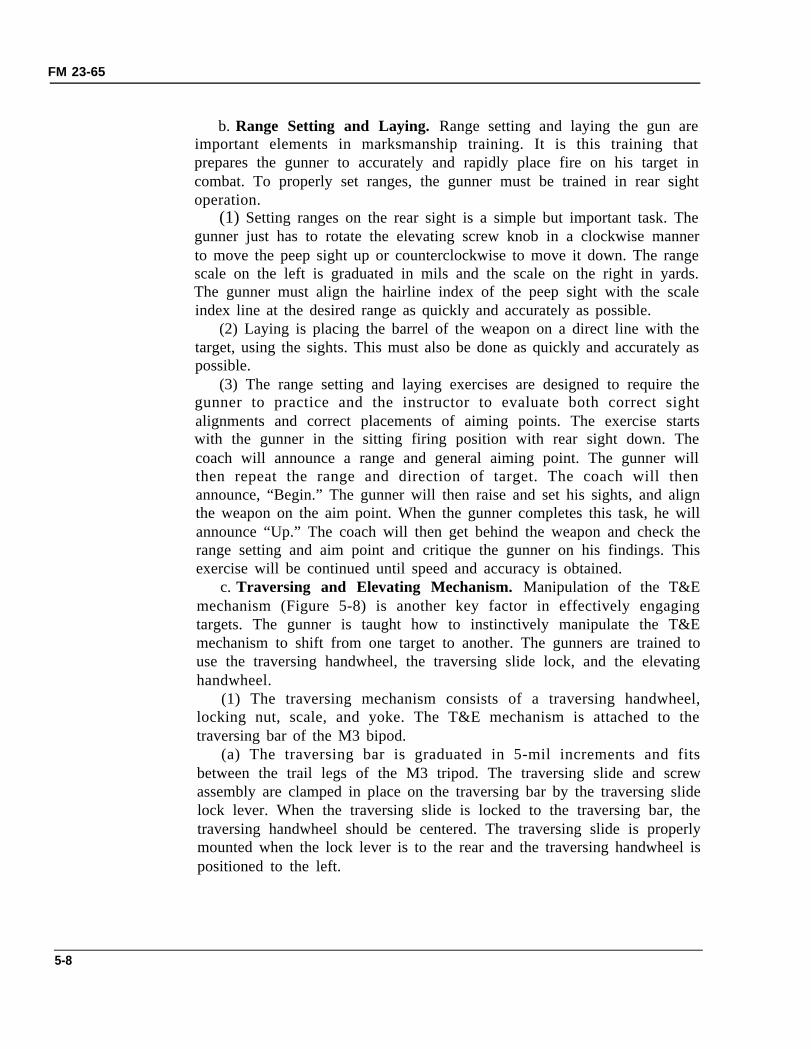
c. Traversing and Elevating Mechanism. Manipulation of the T&Emechanism (Figure 5-8) is another key factor in effectively engagingtargets. The gunner is taught how to instinctively manipulate the T&Emechanism to shift from one target to another. The gunners are trained touse the traversing handwheel, the traversing slide lock, and the elevatinghandwheel.
(1) The traversing mechanism consists of a traversing handwheel,locking nut, scale, and yoke. The T&E mechanism is attached to thetraversing bar of the M3 bipod.
(a) The traversing bar is graduated in 5-mil increments and fitsbetween the trail legs of the M3 tripod. The traversing slide and screwassembly are clamped in place on the traversing bar by the traversing slidelock lever. When the traversing slide is locked to the traversing bar, thetraversing handwheel should be centered. The traversing slide is properlymounted when the lock lever is to the rear and the traversing handwheel ispositioned to the left.
5-8
FM 23-65
Figure 5-8. Traversing and elevating mechanism.
(b) To make changes in direction, loosen the traversing slide locklever and move the slide along the traversing bar. This permits traverse of400 mils left or right of the zero index in the center of the traversing bar.Readings on the traversing bar are taken from the left side of thetraversing slide. For changes of 50 mils or less in deflection, turn thetraversing handwheel. This allows a traverse of 50 mils left or right ofcenter. One click in the traversing handwheel signifies 1 mil change indirection.
(2) The elevating mechanism consists of an upper and lower elevatingscrew, which is connected to the gun by inserting the quick release pinassembly through the holes in the upper elevating screw yoke and the rearmounting lugs of the receiver. A scale, graduated in mils, is fitted to theupper screw to indicate elevation. This scale is marked to show (-) minus250 mils in depression and ( + ) plus 100 mils in elevation from the zerosetting.
5-9
FM 23-65
(3) The elevating handwheel is graduated in 1 mil increments from0 to 50 mils and is fastened to the elevating screw by a screw lock. Thissynchronizes the handwheel graduations with those on the upper elevatingscrew. A spring-actuated index device produces a clicking sound when thehandwheel is turned. Each click equals 1 mil change in elevation. Thehandwheel is turned clockwise to depress the barrel and counterclockwiseto elevate.
(4) Direction and elevation readings constitute the data necessary toengage preselected target areas during limited visibility. These readingsare measured by and recorded from the traversing bar and the T&Emechanism. To obtain accurate readings, the T&E must be first zeroedwith all measurements recorded in mils.
(a) To zero the traversing handwheel, the gunner must first hold theT&E so that the traversing handwheel is on his left as he looks at it. Hethen turns the handwheel toward himself until it stops, loosens the lockingnut slightly, and aligns the zero on the scale with the zero on the elevatingscrew yoke. Once the zeros are aligned, he tightens the locking nut. Hemust then turn the handwheel two complete turns away from the body andstop. The scale should again be on the zero. If this procedure is done atnight, the gunner will turn 50 clicks away from him.
(b) To zero the elevating handwheel, the gunner must first turn thehandwheel up or down until the handwheel is level with the line directlyunder the zero on the elevating screw plate scale, and the elevatinghandwheel indicator is pointing to the zero on the top of the handwheel.The elevating mechanism sleeve is then rotated up until it is stopped bythe handwheel. The gunner then rotates the sleeve down until it stops,making sure he counted each complete rotation. He then divides thenumber of rotations by two, rotates the sleeve back up that number, andstops. The T&E mechanism is now ready to be attached to the tripod.
(c) To obtain and record direction readings, the gunner sets the sighton the proper range to hit the target, loosens the traversing slide locklever, and slides the T&E mechanism along the traversing bar until theweapon is sighted on the aiming point of the target. The T&E mechanismis then locked down by tightening the traversing slide lock lever. Allreadings are taken from the left side of the sleeve mechanism. If the leftside of the sleeve is not exactly on one of the 5-mil tick marks, the gunnermust slide the sleeve to the next smaller tick mark to align it exactly. Thetraversing handwheel is then used to move the weapon back on point ofaim. The direction is now ready to be recorded. The reading is taken fromthe number on the traversing bar and the direction from the direction ofthe barrel of the weapon. If the sleeve mechanism is on the right side of
5-10
FM 23-65
the zero on the traversing bar, then the reading is left; if it is on the leftside of the zero, then it is a right reading. The width of a target may also bemeasured and recorded by first moving the traversing handwheel until thesights are aligned with the right or left side of the target. The clicksrequired to do this measure the width.
NOTE: Before repositioning the weapon for another target, the gunnermust realign the handwheel.
(d) To obtain an elevation reading, the gunner must first ensure thatthe sights are aligned and at the desired aim point of the target. Theelevation reading is made up of two portions, a major reading and a minorreading. The major reading is taken from the elevating screw plate scale.The scale is graduated in 50-mil increments and ranges from a minus (-)250 mils to a plus ( + ) 100 mils with a zero between them. There is anindex line below each number and a plus or minus sign above eachnumber, with the exception of the zero. The zero does not have a plus orminus sign. To obtain the elevation reading, the gunner should lower hishead until his eyes are level with the elevating handwheel. The majorreading is the first number with a plus or minus sign, with its index line justvisible above the elevating handwheel. The minor reading is taken fromthe top surface of the elevating handwheel. It is graduated in l-milincrements for a total of 50 mils. The handwheel is also equipped with anindicator that points to each number on the handwheel as it is turned.Once the gunner has the major reading from the screw plate scale, he willthen get the minor reading by looking at the number at which theindicator is pointing. Both portions of the elevation reading are recordedby placing a slash (/) mark between the two portions.
(e) An elevation reading is valid only on one T&E mechanism. If thesame data is placed on another T&E mechanism using the same weapon,the data may be inaccurate. The number of threads exposed on the T&Emust remain the same both when obtaining and recording data. If thenumber of exposed threads is changed in any manner, the firing will be offtarget. For example, when a gun is freed to engage targets in the secondarysector, the data will be correct if the gunner ensures that the same amountof threads is exposed when he returns to his primary sector of fire.
(f) To ensure that the data is correct, the gunner should fire and adjusthis weapon.
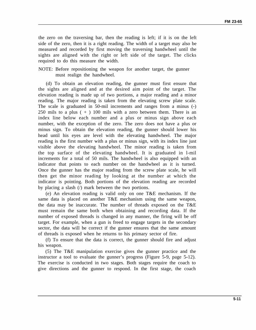
(5) The T&E manipulation exercise gives the gunner practice and theinstructor a tool to evaluate the gunner’s progress (Figure 5-9, page 5-12).The exercise is conducted in two stages. Both stages require the coach togive directions and the gunner to respond. In the first stage, the coach
5-11
FM 23-65
positions himself about 10 paces to the front of the gun. He then directsthe gunner to manipulate the weapon in certain directions. He indicatesthe direction by the use of hand signals. The gunner responds bymanipulating the T&E mechanism with his left hand. The gunner mustkeep his eyes on the coach; at no time during this exercise is he permittedto look at the T&E mechanism. The coach must be very attentive duringthe first stage because the gunner will be manipulating using the elevatinghandwheel and the traversing handwheel. The second stage is done in thesame way except the gunner must make bold changes in elevation anddeflection. The exercise continues until the instructor is satisfied that thegunner can manipulate the weapon by T&E without looking at the device.This exercise can also be conducted using the basic MG target. Thegunner will be shifted from one selected target to another. The coach mustobserve all movements of the gunner during this training.
Figure 5-9. Manipulation exercise.
5-8. RANGE DETERMINATIONRange determination is the process of estimating the distance to a targetfrom a gunner’s position. The ability of the gunner to get the range to,sight on, and destroy a target is the realism of combat. Under combatconditions, ranges are seldom known in advance; therefore theeffectiveness of fire depends largely upon the accuracy and speed of thegunner in determining range. Some methods of determining range areestimating by eye (Table 5-1, page 5-15), firing the gun, measuring rangefrom a map or aerial photograph, stepping off the distance, or securinginformation from other units. Ranges are determined to the nearest100 meters for machine gun firing. In combat, the most commonly usedmethods are estimating by eye and firing the gun. There is also a methodused for measuring lateral distance.
5-12
FM 23-65
a. The two techniques of eye estimation are the 100-meter unit ofmeasure method and the appearance of objects method.
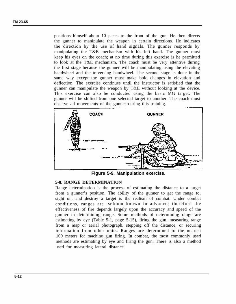
(1) When using the 100-meter unit of measure method, the gunnermust be able to visualize what 100 meters looks like on the ground. Withthis distance in mind, the gunner can mentally determine the number of100-meter units between his position and the target. The accuracy of thismethod is limited to 500 meters or less, and it requires constant practice(Figure 5-10).
Figure 5-10. 100-meter unit of measure method,less than 500 meters.
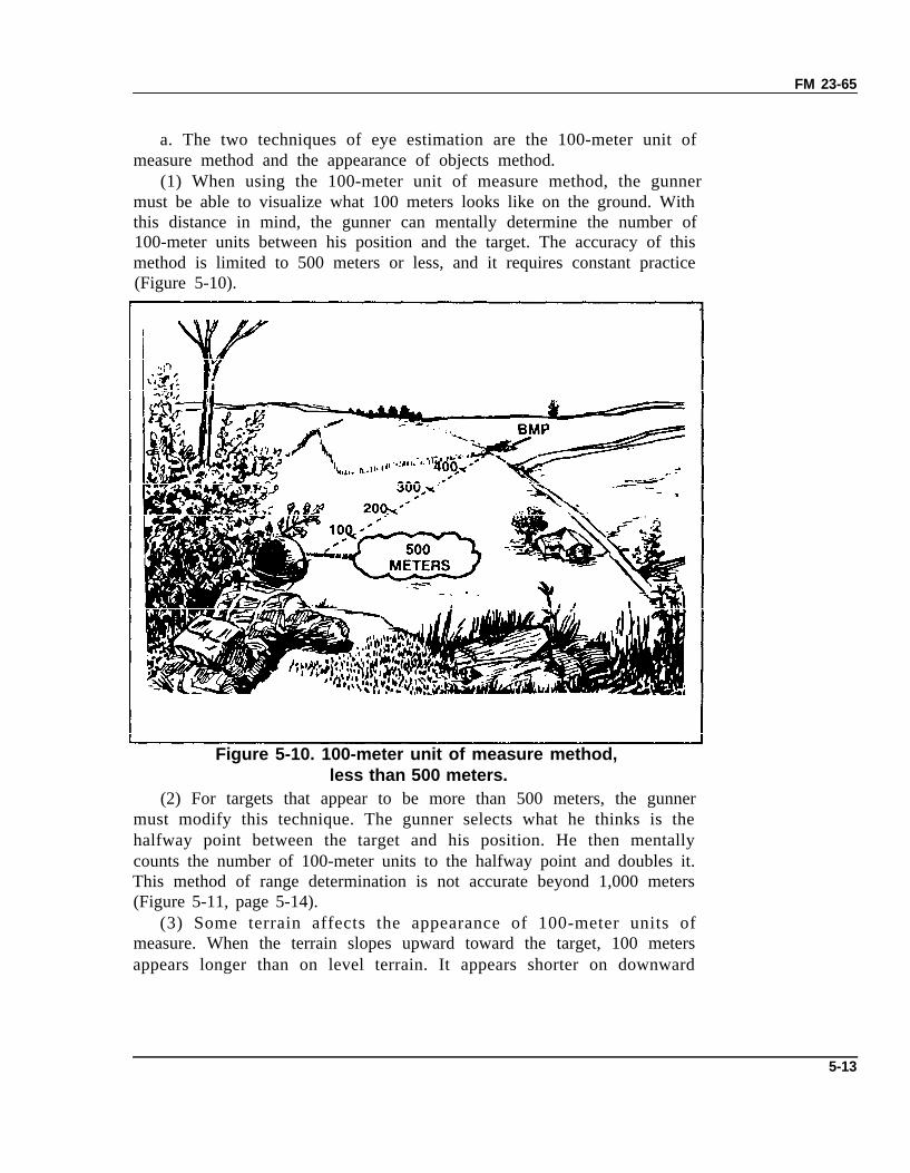
(2) For targets that appear to be more than 500 meters, the gunnermust modify this technique. The gunner selects what he thinks is thehalfway point between the target and his position. He then mentallycounts the number of 100-meter units to the halfway point and doubles it.This method of range determination is not accurate beyond 1,000 meters(Figure 5-11, page 5-14).
(3) Some terrain affects the appearance of 100-meter units ofmeasure. When the terrain slopes upward toward the target, 100 metersappears longer than on level terrain. It appears shorter on downward
5-13
FM 23-65
sloping terrain. The gunner must consider these two factors when usingthe 100-meter unit of measure method.
Figure 5-11. 100-meter unit of measure method,more than 500 meters.
(4) The appearance of objects method may be used if the gunner isunable to use the 100-meter unit of measure method because of terrain.To use this method, the gunner learns through practice how familiarobjects look at various known ranges. This can be achieved by studying theappearance of a man standing 100 meters away. The gunner must then fixthe appearance of the man firmly in his mind to include the size anddetails of his uniform and equipment. Next, he studies the same man atthe same distance in the kneeling and prone positions. This procedure isused at 200, 300, 400, and 500 meters. By comparing the appearance of theman at these known ranges, he can establish a series of mental images thatwill help him determine range on unfamiliar terrain out to 500 meters.This training could also be conducted to familiarize the gunner with otherobjects, such as weapons and vehicles, at various ranges.
5-14
FM 23-65
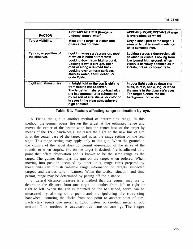
Table 5-1. Factors affecting range estimation by eye.
b. Firing the gun is another method of determining range. In thismethod, the gunner opens fire on the target at the estimated range andmoves the center of the beaten zone into the center base of the target bymeans of the T&E handwheels. He resets the sight so the new line of aimis at the center base of the target and notes the range setting on the rearsight. This range setting may apply only to this gun. When the ground inthe vicinity of the target does not permit observation of the strike of therounds, or when surprise fire on the target is desired, fire is adjusted on apoint that offers observation and is known to be the same range as thetarget. The gunner then lays his gun on the target when ordered. Whenmoving into position occupied by other units, range cards prepared bythose units can furnish valuable range information on targets, suspectedtargets, and various terrain features. When the tactical situation and timepermit, range may be determined by pacing off the distance.
c. Lateral distance measure is a method that the gunner may use todetermine the distance from one target to another from left to right orright to left. When the gun is mounted on the M3 tripod, width can bemeasured by aiming on a point and manipulating the traversinghandwheel, counting the clicks from one point to another point of aim.Each click equals one meter at 1,000 meters or one-half meter at 500meters. This method is accurate but time-consuming. The finger
5-15
FM 23-65
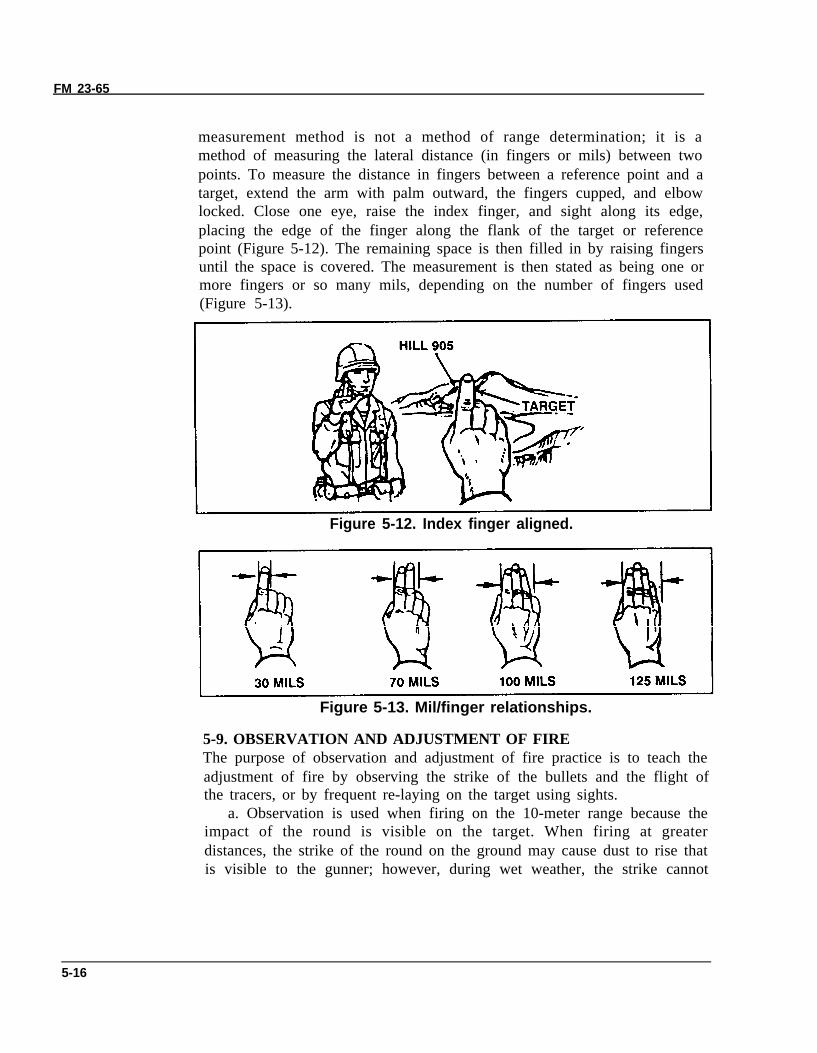
measurement method is not a method of range determination; it is amethod of measuring the lateral distance (in fingers or mils) between twopoints. To measure the distance in fingers between a reference point and atarget, extend the arm with palm outward, the fingers cupped, and elbowlocked. Close one eye, raise the index finger, and sight along its edge,placing the edge of the finger along the flank of the target or referencepoint (Figure 5-12). The remaining space is then filled in by raising fingersuntil the space is covered. The measurement is then stated as being one ormore fingers or so many mils, depending on the number of fingers used(Figure 5-13).
Figure 5-12. Index finger aligned.
Figure 5-13. Mil/finger relationships.
5-9. OBSERVATION AND ADJUSTMENT OF FIREThe purpose of observation and adjustment of fire practice is to teach theadjustment of fire by observing the strike of the bullets and the flight ofthe tracers, or by frequent re-laying on the target using sights.
a. Observation is used when firing on the 10-meter range because theimpact of the round is visible on the target. When firing at greaterdistances, the strike of the round on the ground may cause dust to rise thatis visible to the gunner; however, during wet weather, the strike cannot
5-16
FM 23-65
always be seen. In this case, use tracer ammunition that allows the gunneror crew to note the strike of the burst in relation to the target.
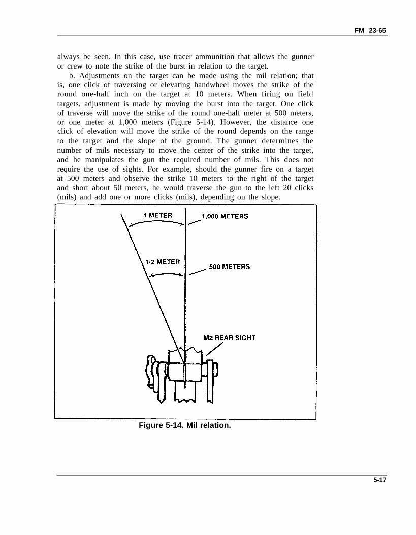
b. Adjustments on the target can be made using the mil relation; thatis, one click of traversing or elevating handwheel moves the strike of theround one-half inch on the target at 10 meters. When firing on fieldtargets, adjustment is made by moving the burst into the target. One clickof traverse will move the strike of the round one-half meter at 500 meters,or one meter at 1,000 meters (Figure 5-14). However, the distance oneclick of elevation will move the strike of the round depends on the rangeto the target and the slope of the ground. The gunner determines thenumber of mils necessary to move the center of the strike into the target,and he manipulates the gun the required number of mils. This does notrequire the use of sights. For example, should the gunner fire on a targetat 500 meters and observe the strike 10 meters to the right of the targetand short about 50 meters, he would traverse the gun to the left 20 clicks(mils) and add one or more clicks (mils), depending on the slope.
Figure 5-14. Mil relation.
5-17
FM 23-65
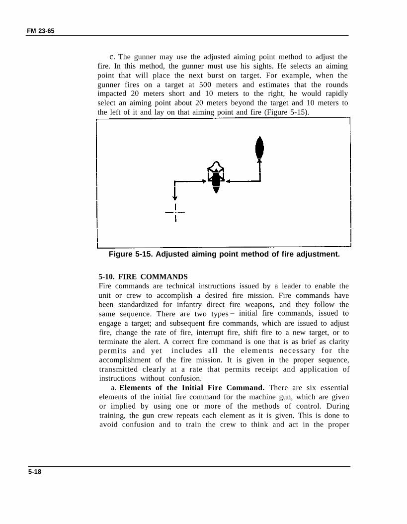
c. The gunner may use the adjusted aiming point method to adjust thefire. In this method, the gunner must use his sights. He selects an aimingpoint that will place the next burst on target. For example, when thegunner fires on a target at 500 meters and estimates that the roundsimpacted 20 meters short and 10 meters to the right, he would rapidlyselect an aiming point about 20 meters beyond the target and 10 meters tothe left of it and lay on that aiming point and fire (Figure 5-15).
Figure 5-15. Adjusted aiming point method of fire adjustment.
5-10. FIRE COMMANDSFire commands are technical instructions issued by a leader to enable theunit or crew to accomplish a desired fire mission. Fire commands havebeen standardized for infantry direct fire weapons, and they follow thesame sequence. There are two types – initial fire commands, issued toengage a target; and subsequent fire commands, which are issued to adjustfire, change the rate of fire, interrupt fire, shift fire to a new target, or toterminate the alert. A correct fire command is one that is as brief as claritypermits and yet includes all the elements necessary for theaccomplishment of the fire mission. It is given in the proper sequence,transmitted clearly at a rate that permits receipt and application ofinstructions without confusion.
a. Elements of the Initial Fire Command. There are six essentialelements of the initial fire command for the machine gun, which are givenor implied by using one or more of the methods of control. Duringtraining, the gun crew repeats each element as it is given. This is done toavoid confusion and to train the crew to think and act in the proper
5-18
FM 23-65
sequence. The six elements are the alert, direction, description, range,method of fire, and the command to open fire.
(1) Alert. This element brings the crew to a state of readiness toreceive further instructions. Once alerted, the gunner ensures the gun isloaded. The assistant gunner continuously checks with the leader fororders or instructions and passes them on to the gunner. The oral alert isannounced as FIRE MISSION. At this command, the gunners are alertedthat a target has been detected and fire may be delivered upon it. Whenthe leader announces the alert, such as FIRE MISSION, both gun crewsreact to the alert. If only a certain gun is to engage, the leader announcesNUMBER 1 (or 2). The other crew follows the fire mission, loads, andlays on the target to take up the fire, if required.
(2) Direction. This element indicates the general direction to thetarget and may be given in one or a combination of the following ways:
(a) The leader gives the direction orally to the target in relation to theposition of the gun(s). For example, FRONT, RIGHT FRONT, LEFTFRONT.
(b) The leader can designate a small or obscure target by pointingwith his arm and hand or aiming the machine gun. When pointing with hisarm and hand, a man standing behind him should be able to look over hisshoulder and sight along his arm and index finger to locate the target.When a gun has been aimed at a target, a soldier looking through thesights should be able to see the target.
(c) Tracer ammunition is a quick and sure method of designating atarget that is not clearly visible. When using this method, the leader shouldfirst give the general direction to direct the gun crew’s attention to thedesired area. To minimize the loss of surprise when using tracerammunition, the leader does not fire until he has given all the elements ofthe fire command except the command to fire. The leader may use hisindividual weapon or fire one or more bursts from the machine gun. Thefiring of the tracer(s) then becomes the last element of the fire commandand is the signal to open fire. For example:
FIRE MISSION.FRONT.BUNKER.WATCH MY TRACER(S).SLOW (or SINGLE SHOT).
The leader fires his individual weapon or a machine gun at the enemybunker, then his gun crew(s) opens fire.
(d) Another method of designating obscure targets is by using easilyrecognizable reference points. Prominent terrain features and man-made
5-19
FM 23-65
objects make good reference points. All leaders and members of thecrew(s) must be familiar with the terrain features and the terminologyused to describe them. The general direction to the reference point shouldbe given. For example:
FIRE MISSION, NUMBER 2.FRONT.REFERENCE: LONE PINE TREE.TARGET: TRUCK.
Sometimes a target must be designated by using successive referencepoints. For example:
FIRE MISSION, NUMBER 1.RIGHT FRONT.REFERENCE: RED-ROOFED HOUSE, LEFT TO HAYSTACK,LEFT TO BARN.TARGET: MACHINE GUN.
Finger measurements can be used to direct the gun crew’s attention to theright or left of reference points. For example:
Whenpoints
FIRE MISSION.LEFT FRONT.REFERENCE: CROSSROAD. RIGHT FOUR FINGERS.TARGET: LINE OF TROOPS.the guns are mounted on tripods, lateral distance from referencecan be accurately announced. When gunners are firing the
tripod-mounted gun, lateral distance is assumed to be in mils unlessotherwise indicated, so the word “mils” is not necessary. For example:
FIRE MISSION.FRONT.REFERENCE: KNOCKED-OUT TANK. LEFT FOUR ZERO.TARGET: COLUMN OF TROOPS.
(3) Description. The target description is used to create a picture ofthe target in the minds of the gun crew. The gun crew must know the typeof target they are to engage to properly apply their fire. The leader shoulddescribe it briefly but accurately. For example:
Dismounted enemy personnel . . . . . . . . . . . . . . . . . . . . . . . . . . . . . . . . . . . TROOPS
Automatic weapons . . . . . . . . . . . . . . . . . . . . . . . . . . . . . . . . . . . . . . . MACHINE GUN
Armored vehicles . . . . . . . . . . . . . . . . . . . . . . . . . . . . . . . . . . . . . . . . . . . . . . . . . . . . . . . . . . . . . TANK
Artillery or antitank weapon . . . . . . . . . . . . . . . . . . . . . . . . . . . . . . . . . ANTITANK
Airplanes or helicopters . . . . . . . . . . . . . . . . . . . . . . . . . . . . . . . . . . . . . . . . AIRCRAFT
If the target is obvious, no description is necessary. Finger measurementsor mil measurements can be used to designate the width of a linear targetwhen the flanks cannot be pinpointed.
5 - 2 0
FM 23-65
(4) Range. The range to the target is given so the gun crew knows howfar to look for the target and immediately knows what range setting toplace on the rear sight. Range is determined and announced in meters.Since the meter is the standard unit of range measurement, the word“meters” is not announced. With machine guns, the range is determinedand announced in even hundreds and thousands. For example: THREEHUNDRED, ONE THOUSAND, ONE ONE HUNDRED. This elementmay be omitted when the gunners can obviously determine the range;however, it is desirable in some situations to announce the range.
(5) Method of fire. This element includes manipulation and rate offire.
(a) Manipulation is used to prescribe the class of fire with respect tothe gun. It is announced FIXED, TRAVERSE, SEARCH, TRAVERSEAND SEARCH, SWINGING TRAVERSE, or FREE GUN.
(b) To control the rate of fire, the gunner may use single shot, slow,rapid, or cyclic.
•
•
•
•
(6)
Single shot. Place the gun in the single-shot mode and engage thetarget with aimed shots. The MG is accurate out to 1,500 meters.Slow fire. Slow fire consists of less than 40 rounds per minute, inbursts of five to seven rounds, fired at 10- to 15-second intervals.Rapid fire. Rapid fire consists of more than 40 rounds per minute,fired in bursts of five to seven rounds, at 5- to 10-second intervals.Cyclic fire. Cyclic fire is when the weapon fires 450 to 550 roundsper minute.
Command to open fire. If surprise fire is not desired, the commandFIRE is given without pause. It is often important that machine gun fire bewithheld for maximum effect of surprise fire. To ensure this, the leadermay preface the command to commence firing with the words AT MYCOMMAND or AT MY SIGNAL. When the gunner(s) is ready to engagethe target, he reports UP to the assistant gunner(s) who signals READYto the leader. For example:
FIRE MISSION.FRONT.TROOPS.AT MY COMMAND. (Pause until crew members are readyand fire is desired.)FIRE (or appropriate arm-and-hand signal).
5-21
FM 23-65
When the leader makes a mistake in the initial fire command, he correctsit by announcing CORRECTION, and then gives the correctedelement(s). For example:
FIRE MISSION.FRONT.TROOPS.FIVE HUNDRED.CORRECTION.SIX HUNDRED.TRAVERSE.AT MY COMMAND.
When the leader makes an error in the subsequent fire command, he maycorrect it by announcing CORRECTION, and then repeating the entiresubsequent fire command. For example:
LEFT FIVE, DROP ONE.CORRECTIONLEFT FIVE, DROP ONE ZERO.
b. Subsequent Fire Commands. If the gunner fails to adjust his fire onthe target, the leader must promptly correct him by announcing orsignaling the desired changes. When changes are given, the gunner makesthe required corrections and continues to engage the target withoutfurther command. When firing under the control of a leader, the assistantgunner checks with the leader for instructions, which he passes on to thegunner. Changes in the rate of fire are given orally and by arm-and-handsignals. To interrupt firing, the leader announces CEASE FIRE or gives asignal to cease fire. The gun crew(s) remains on the alert and firing can beresumed on the same target by announcing FIRE. To terminate the alert,the leader announces CEASE FIRE, END OF MISSION.
5-11. CREW EXERCISESThe purpose of crew exercise is to develop precision, speed, skill, andteamwork in examining equipment, placing the gun into action, and takingit out of action. In crew exercise, precision must be stressed. Once that isattained, speed, skill, and teamwork will follow. Duties are rotated duringcrew exercise to allow each member of the gun crew to become familiarwith all the duties. During crew exercise, all oral or visual signals arerepeated. When the fire command is completed, the gunner will give theassistant gunner an UP. The assistant gunner will extend his hand and arminto the air in the direction of the leader (to indicate READY) andannounce, UP. With the M3 mount, the crew must consist of at least fourmen, including the leader. There is no designated crew in the TOE for a
5-22
FM 23-65
dismounted caliber .50 MG. The following paragraphs are onlysuggestions for the breakdown of equipment and member designation thatmay be established by the commander.
a. Crew Equipment. In addition to individual arms and equipment,crew members carry the following equipment for the tripod-mountedmachine gun:
CREW MEMBER
Squad or crew leader.
No. 1 Assistant gunner.
No. 2 Gunner.
No. 3 Ammunition bearer.
b. Form for CrewCREW DRILL.
(1) Positions withcrew leader with fiveare in the following
SUGGESTED MINIMUM EQUIPMENT
Binoculars, compass, one box ofammunition.
Tripod.
Receiver, T&E mechanism attached,and headspace and timing gauge.
Barrel, barrel cover, and box ofammunition.
Exercise. The crew leader commands, FORM FOR
equipment. The crew forms in column, facing thepaces between men (Figure 5-16, page 5-24). Theyorder: assistant gunner, gunner, and ammunition
bearer. When the crew members reach their correct positions, theyassume the prone position with equipment arranged as follows:
(a) No. 1: Tripod to his left, trail legs to the rear, front leg uppermost.(b) No. 2: Receiver across his front, backplate to the right, retracting
slide handle uppermost.(c) No. 3: Barrel to his right, muzzle to the rear, ammunition box to
his left front with latch to the right (latch to the front for the new box).(d) Other members, if present: Ammunition boxes in front, one foot
apart, latches to the right (front).(e) Crew leader: Ammunition box to his right as he faces the crew,
latch to the right (front).(2) Rotation of duties. Duties are rotated to ensure that each member
learns and is capable of performing the duties of the other members.(a) The command to rotate all personnel is, FALL OUT LEADER.
At this command, each member of the crew rises, moves forward, andassumes a new duty. The crew leader becomes the ammunition bearer.The assistant gunner moves forward and becomes the crew leader. Thegunner moves forward and becomes the assistant gunner. The ammunitionbearer moves forward and becomes the gunner.
5-23
FM 23-65
(b) I f the leader i s not changed, the command, FALL OUTASSISTANT GUNNER, is given. At this command, the crew membersrise, the gunner becomes the assistant gunner, the ammunition bearerbecomes the gunner, and the assistant gunner becomes the ammunitionbearer. When the crew members have assumed their new position, theycall out their new duties in order, ASSISTANT GUNNER, GUNNER,AMMUNITION BEARER.
NOTE: An additional crew exercise, which the crew maybe required topractice, is the setting of headspace and timing. These proceduresare outlined in paragraph 3-6.
Figure 5-16. Crew formed in column.
c. Inspection of Equipment Before Firing. When the crew is formedwith equipment, the command is, INSPECT EQUIPMENT BEFOREFIRING. At this command, the crew proceeds as follows:
(1) The assistant gunner inspects the tripod M3 mount to ensure that:(a) The indexing levers and clamps on the front and trail legs function
properly, and the legs are in the short (low) position.(b) The front leg and trail legs are closely folded, and the front leg
clamp is hand tight.(c) The sleeve lock latch and pintle lock release cam are in working
order, and the pintle lock release cam is down.(d) The pintle bushing is free from dirt and burrs.(2) The gunner inspects the receiver group to ensure that:
5-24
FM 23-65
(a) The barrel support and breech bearing are free of dirt.(b) The gun pintle is free of dirt.(c) The feed mechanism and bolt switch are properly assembled to
feed from left (soldier raises cover for proper inspection).(d) The striker projects through the aperture in the face of bolt
(soldier closes the cover).(e) The rear sight is set at 1,000 yards (900 meters) windage zero.(f) The T&E mechanism is securely attached to the receiver.(g) The traversing handwheel is centered.(h) The elevating screws are equally exposed (about 2 inches) above
and below elevating handwheel.(i) The backplate is latched and locked in place.(j) The bolt latch release is locked in the down position by the bolt
latch release lock.(3) The ammunition bearer inspects the barrel and ammunition box to
ensure that:(a) The barrel is clear.(b) The barrel carrier assembly is securely attached to the barrel.(c) The barrel threads are free of dirt.(d) The metallic links are clean (soldier opens ammunition box).(e) The belt is properly loaded and placed in box with the
double-looped end up.(f) Dummy ammunition is used during crew exercise, and no live
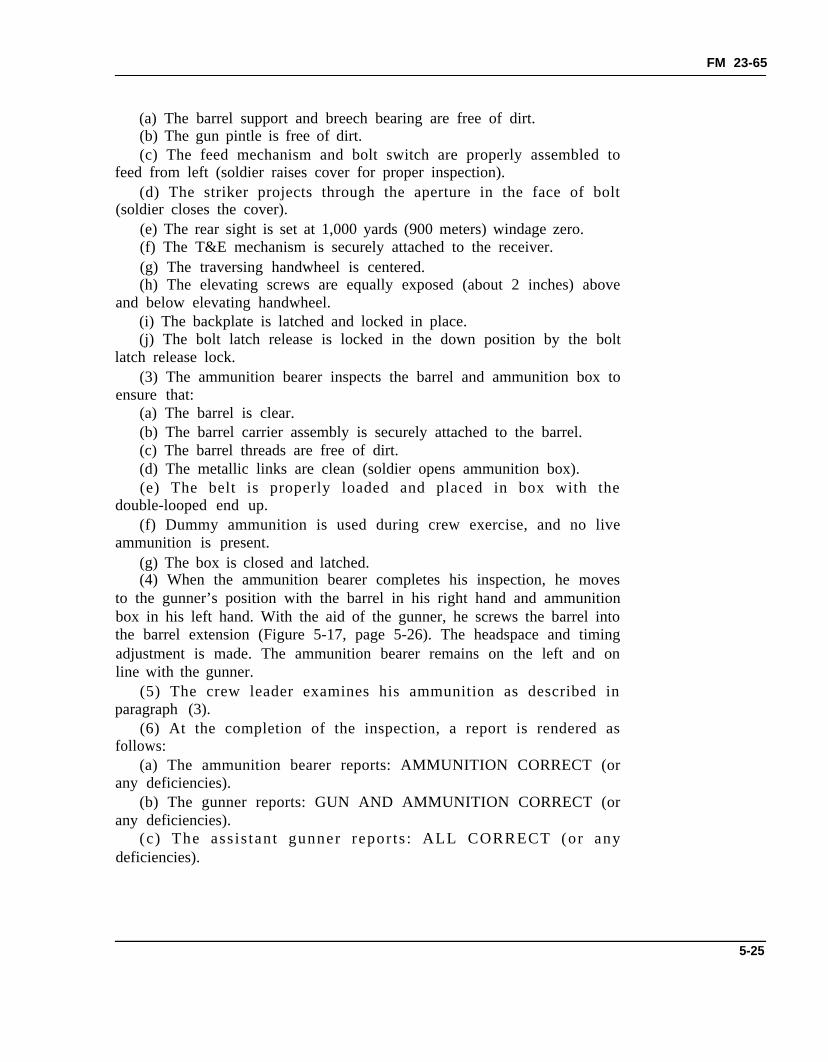
ammunition is present.(g) The box is closed and latched.(4) When the ammunition bearer completes his inspection, he moves
to the gunner’s position with the barrel in his right hand and ammunitionbox in his left hand. With the aid of the gunner, he screws the barrel intothe barrel extension (Figure 5-17, page 5-26). The headspace and timingadjustment is made. The ammunition bearer remains on the left and online with the gunner.
(5) The crew leader examines his ammunition as described inparagraph (3).
(6) At the completion of the inspection, a report is rendered asfollows:
(a) The ammunition bearer reports: AMMUNITION CORRECT (orany deficiencies).
(b) The gunner reports: GUN AND AMMUNITION CORRECT (orany deficiencies).
(c) The ass is tant gunner repor ts : ALL CORRECT (or anydeficiencies).
5-25
FM 23-65
Figure 5-17. Screwing the barrel into the barrel extension.
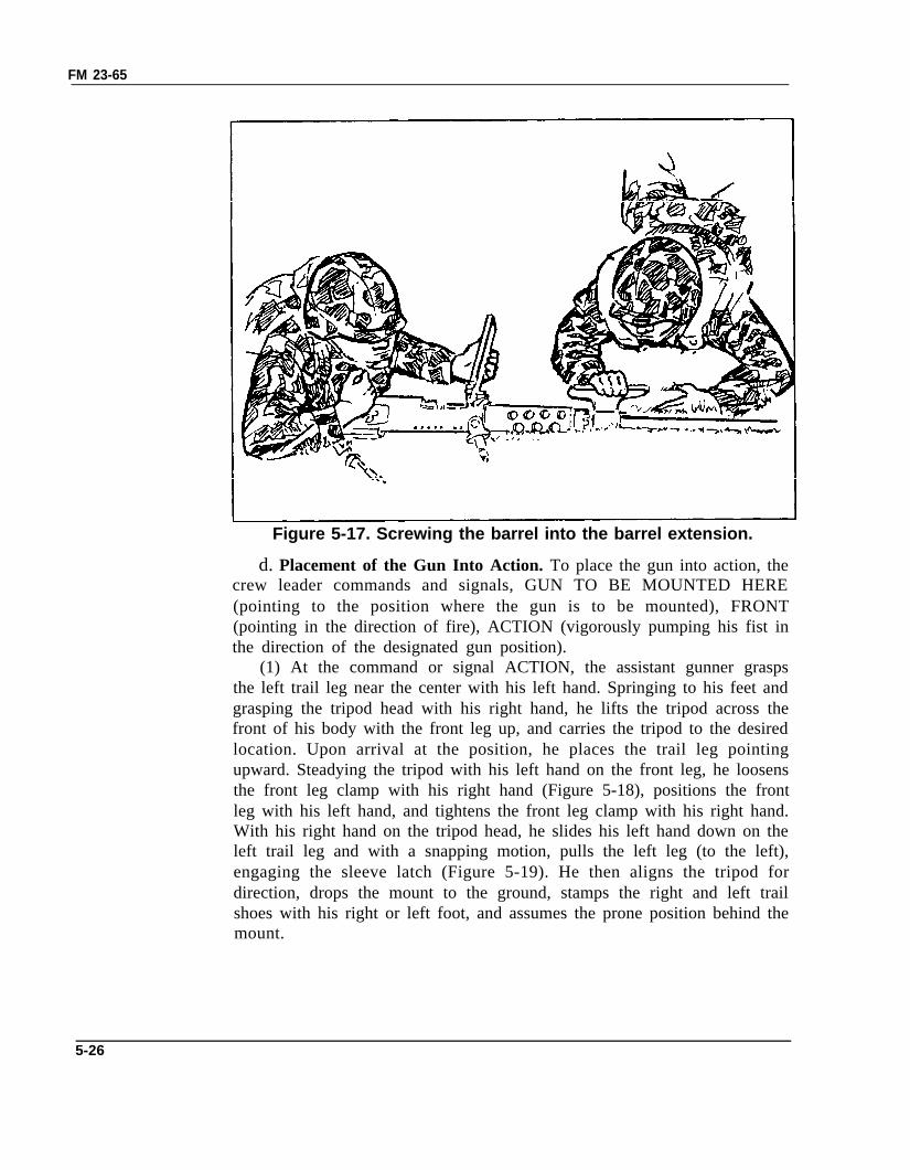
d. Placement of the Gun Into Action. To place the gun into action, thecrew leader commands and signals, GUN TO BE MOUNTED HERE(pointing to the position where the gun is to be mounted), FRONT(pointing in the direction of fire), ACTION (vigorously pumping his fist inthe direction of the designated gun position).
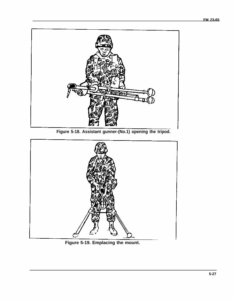
(1) At the command or signal ACTION, the assistant gunner graspsthe left trail leg near the center with his left hand. Springing to his feet andgrasping the tripod head with his right hand, he lifts the tripod across thefront of his body with the front leg up, and carries the tripod to the desiredlocation. Upon arrival at the position, he places the trail leg pointingupward. Steadying the tripod with his left hand on the front leg, he loosensthe front leg clamp with his right hand (Figure 5-18), positions the frontleg with his left hand, and tightens the front leg clamp with his right hand.With his right hand on the tripod head, he slides his left hand down on theleft trail leg and with a snapping motion, pulls the left leg (to the left),engaging the sleeve latch (Figure 5-19). He then aligns the tripod fordirection, drops the mount to the ground, stamps the right and left trailshoes with his right or left foot, and assumes the prone position behind themount.
5-26
FM 23-65
Figure 5-18. Assistant gunner-(No.1) opening the tripod.
Figure 5-19. Emplacing the mount.
5-27
FM 23-65
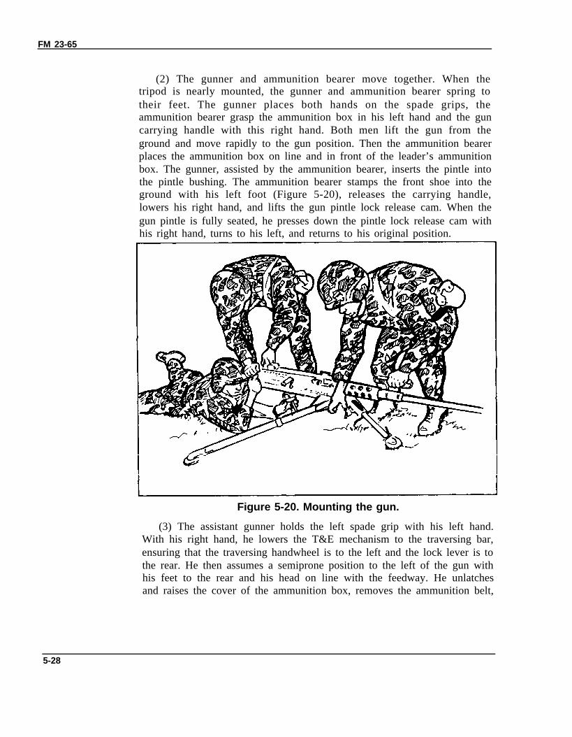
(2) The gunner and ammunition bearer move together. When thetripod is nearly mounted, the gunner and ammunition bearer spring totheir feet. The gunner places both hands on the spade grips, theammunition bearer grasp the ammunition box in his left hand and the guncarrying handle with this right hand. Both men lift the gun from theground and move rapidly to the gun position. Then the ammunition bearerplaces the ammunition box on line and in front of the leader’s ammunitionbox. The gunner, assisted by the ammunition bearer, inserts the pintle intothe pintle bushing. The ammunition bearer stamps the front shoe into theground with his left foot (Figure 5-20), releases the carrying handle,lowers his right hand, and lifts the gun pintle lock release cam. When thegun pintle is fully seated, he presses down the pintle lock release cam withhis right hand, turns to his left, and returns to his original position.
Figure 5-20. Mounting the gun.
(3) The assistant gunner holds the left spade grip with his left hand.With his right hand, he lowers the T&E mechanism to the traversing bar,ensuring that the traversing handwheel is to the left and the lock lever is tothe rear. He then assumes a semiprone position to the left of the gun withhis feet to the rear and his head on line with the feedway. He unlatchesand raises the cover of the ammunition box, removes the ammunition belt,
5-28
FM 23-65
inserts the double-looped end into the feedway, and taps the feedway withhis right hand to ensure it is closed.
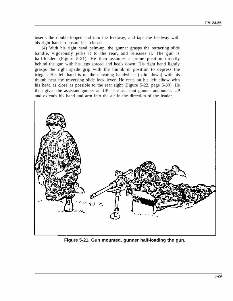
(4) With his right hand palm-up, the gunner grasps the retracting slidehandle, vigorously jerks it to the rear, and releases it. The gun ishalf-loaded (Figure 5-21). He then assumes a prone position directlybehind the gun with his legs spread and heels down. His right hand lightlygrasps the right spade grip with the thumb in position to depress thetrigger. His left hand is on the elevating handwheel (palm down) with histhumb near the traversing slide lock lever. He rests on his left elbow withhis head as close as possible to the rear sight (Figure 5-22, page 5-30). Hethen gives the assistant gunner an UP. The assistant gunner announces UPand extends his hand and arm into the air in the direction of the leader.
Figure 5-21. Gun mounted, gunner half-loading the gun.
5-29
FM 23-65
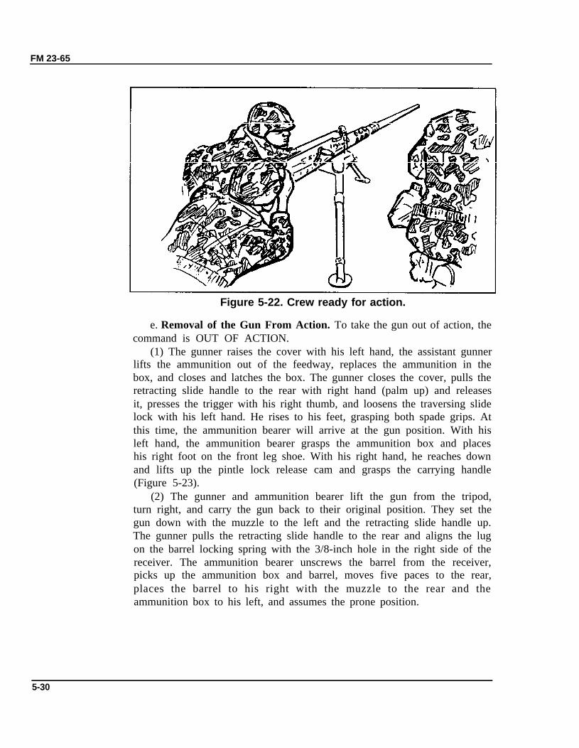
Figure 5-22. Crew ready for action.
e. Removal of the Gun From Action. To take the gun out of action, thecommand is OUT OF ACTION.
(1) The gunner raises the cover with his left hand, the assistant gunnerlifts the ammunition out of the feedway, replaces the ammunition in thebox, and closes and latches the box. The gunner closes the cover, pulls theretracting slide handle to the rear with right hand (palm up) and releasesit, presses the trigger with his right thumb, and loosens the traversing slidelock with his left hand. He rises to his feet, grasping both spade grips. Atthis time, the ammunition bearer will arrive at the gun position. With hisleft hand, the ammunition bearer grasps the ammunition box and placeshis right foot on the front leg shoe. With his right hand, he reaches downand lifts up the pintle lock release cam and grasps the carrying handle(Figure 5-23).
(2) The gunner and ammunition bearer lift the gun from the tripod,turn right, and carry the gun back to their original position. They set thegun down with the muzzle to the left and the retracting slide handle up.The gunner pulls the retracting slide handle to the rear and aligns the lugon the barrel locking spring with the 3/8-inch hole in the right side of thereceiver. The ammunition bearer unscrews the barrel from the receiver,picks up the ammunition box and barrel, moves five paces to the rear,places the barrel to his right with the muzzle to the rear and theammunition box to his left, and assumes the prone position.
5-30
FM 23-65
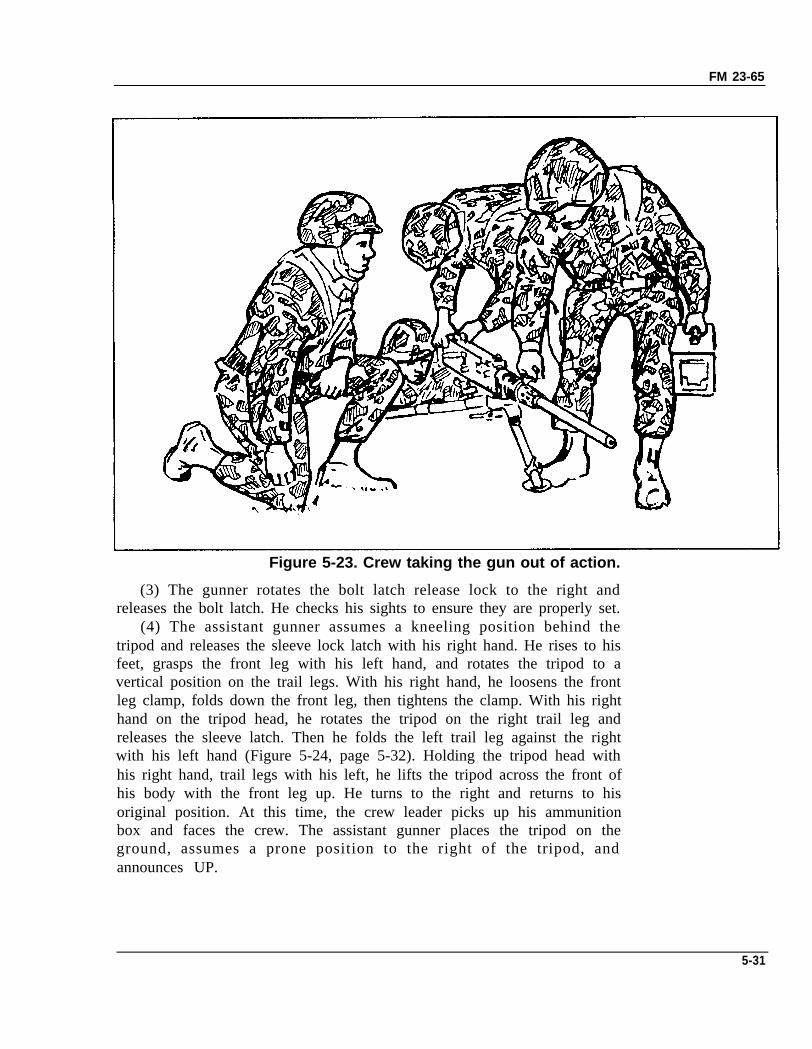
Figure 5-23. Crew taking the gun out of action.
(3) The gunner rotates the bolt latch release lock to the right andreleases the bolt latch. He checks his sights to ensure they are properly set.
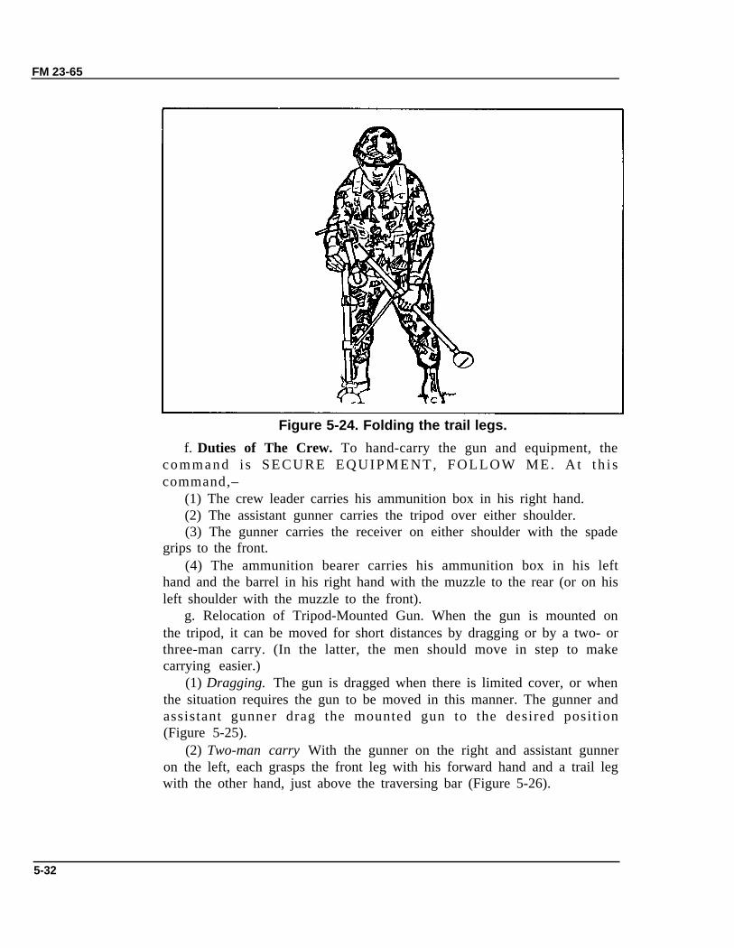
(4) The assistant gunner assumes a kneeling position behind thetripod and releases the sleeve lock latch with his right hand. He rises to hisfeet, grasps the front leg with his left hand, and rotates the tripod to avertical position on the trail legs. With his right hand, he loosens the frontleg clamp, folds down the front leg, then tightens the clamp. With his righthand on the tripod head, he rotates the tripod on the right trail leg andreleases the sleeve latch. Then he folds the left trail leg against the rightwith his left hand (Figure 5-24, page 5-32). Holding the tripod head withhis right hand, trail legs with his left, he lifts the tripod across the front ofhis body with the front leg up. He turns to the right and returns to hisoriginal position. At this time, the crew leader picks up his ammunitionbox and faces the crew. The assistant gunner places the tripod on theground, assumes a prone position to the right of the tripod, andannounces UP.
5-31
FM 23-65
Figure 5-24. Folding the trail legs.
f. Duties of The Crew. To hand-carry the gun and equipment, thecommand i s SECURE EQUIPMENT, FOLLOW ME. A t t h i scommand,–
(1) The crew leader carries his ammunition box in his right hand.(2) The assistant gunner carries the tripod over either shoulder.(3) The gunner carries the receiver on either shoulder with the spade
grips to the front.(4) The ammunition bearer carries his ammunition box in his left
hand and the barrel in his right hand with the muzzle to the rear (or on hisleft shoulder with the muzzle to the front).
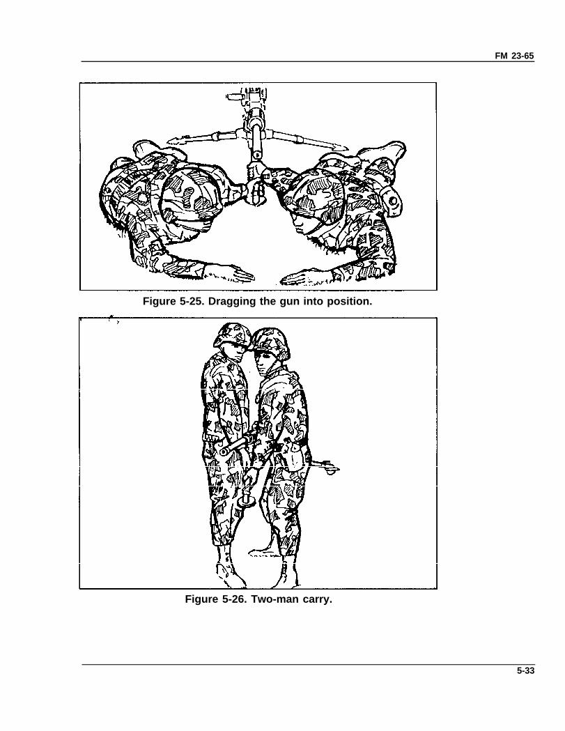
g. Relocation of Tripod-Mounted Gun. When the gun is mounted onthe tripod, it can be moved for short distances by dragging or by a two- orthree-man carry. (In the latter, the men should move in step to makecarrying easier.)
(1) Dragging. The gun is dragged when there is limited cover, or whenthe situation requires the gun to be moved in this manner. The gunner andassistant gunner drag the mounted gun to the desired position(Figure 5-25).
(2) Two-man carry With the gunner on the right and assistant gunneron the left, each grasps the front leg with his forward hand and a trail legwith the other hand, just above the traversing bar (Figure 5-26).
5-32
FM 23-65
Figure 5-25. Dragging the gun into position.
Figure 5-26. Two-man carry.
5-33
FM 23-65
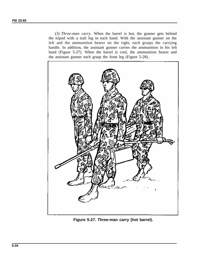
(3) Three-man carry. When the barrel is hot, the gunner gets behindthe tripod with a trail leg in each hand. With the assistant gunner on theleft and the ammunition bearer on the right, each grasps the carryinghandle. In addition, the assistant gunner carries the ammunition in his lefthand (Figure 5-27). When the barrel is cool, the ammunition bearer andthe assistant gunner each grasp the front leg (Figure 5-28).
Figure 5-27. Three-man carry (hot barrel).
5-34
FM 23-65
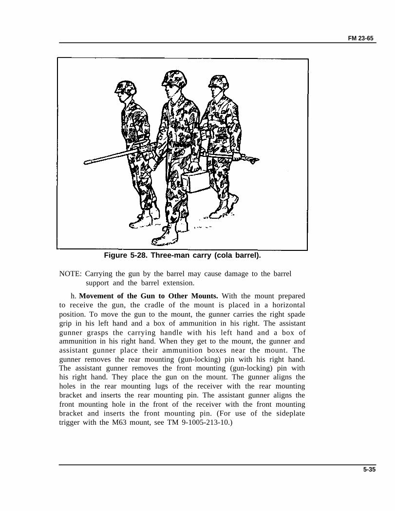
Figure 5-28. Three-man carry (cola barrel).
NOTE: Carrying the gun by the barrel may cause damage to the barrelsupport and the barrel extension.
h. Movement of the Gun to Other Mounts. With the mount preparedto receive the gun, the cradle of the mount is placed in a horizontalposition. To move the gun to the mount, the gunner carries the right spadegrip in his left hand and a box of ammunition in his right. The assistantgunner grasps the carrying handle with his left hand and a box ofammunition in his right hand. When they get to the mount, the gunner andassistant gunner place their ammunition boxes near the mount. Thegunner removes the rear mounting (gun-locking) pin with his right hand.The assistant gunner removes the front mounting (gun-locking) pin withhis right hand. They place the gun on the mount. The gunner aligns theholes in the rear mounting lugs of the receiver with the rear mountingbracket and inserts the rear mounting pin. The assistant gunner aligns thefront mounting hole in the front of the receiver with the front mountingbracket and inserts the front mounting pin. (For use of the sideplatetrigger with the M63 mount, see TM 9-1005-213-10.)
5-35

FM 23-65
5-12. MACHINE GUN FUNDAMENTAL SKILLS TESTThe machine gun fundamental skills test should be held periodically toensure that proficiency with the MG is maintained by all crewmen. Itconsists of 10 fundamental skills; all tasks are hands-on (Figure 5-29). Thetest should be given prior to range firing on a go/no-go basis.
Figure 5-29. The MG fundamental skills test.
Section III. BASIC MARKSMANSHIP
This phase of training is designed to allow the gunner to apply thefundamentals of marksmanship that he learned earlier. During thistraining, the gunner is introduced to the basic machine gun target (seeAppendix C), procedures for both the 10-meter and field fire ranges, andhow to acquire targets. He also fires practice and qualification.
5-13. CONCEPT OF ZEROING/TARGETINGThe concept of zero is very simple; it is no more than the best way toadjust the sights of the weapon so the point of aim of the sights and thepoint of impact of the rounds are the same at any given range. A properlyzeroed M2 gives the gunner the highest probability of hit for most combattargets with the least adjustment to the point of aim. There are threemethods of zeroing/targeting used with the .50 caliber MG.
a. Ten-meter zero is the basic and the most common method ofzeroing the M2 MG. Once zeroed on a 10-meter range using the standardmachine gun target, the weapon is ready for field fire. As other weapons,the sight on the M2 must also be set at an initial start point (Figure 5-30).The initial sight setting for field zero is basically the same; except therange setting during field zero will depend on the range to the target, andit is always 1,000 yards for 10 meters.
5-36
FM 23-65
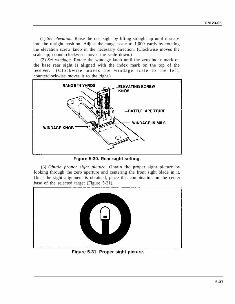
(1) Set elevation. Raise the rear sight by lifting straight up until it snapsinto the upright position. Adjust the range scale to 1,000 yards by rotatingthe elevation screw knob in the necessary direction. (Clockwise moves thescale up; counterclockwise moves the scale down.)
(2) Set windage. Rotate the windage knob until the zero index mark onthe base rear sight is aligned with the index mark on the top of thereceiver. ( C l o c k w i s e m o v e s t h e w i n d a g e s c a l e t o t h e l e f t ;counterclockwise moves it to the right.)
Figure 5-30. Rear sight setting.
(3) Obtain proper sight picture. Obtain the proper sight picture bylooking through the zero aperture and centering the front sight blade in it.Once the sight alignment is obtained, place this combination on the centerbase of the selected target (Figure 5-31).
Figure 5-31. Proper sight picture.
5-37
FM 23-65
b. Field zeroing/targeting is an expedient method of obtaining a zerowhen a 10-meter zero cannot be conducted. When preparing to field zero,make sure the M2 is mounted securely on the M3 tripod, make sure theT&E is working properly, and finally, know the distance to your zerotarget. The only difference in initial sight setting for field zero is rangesetting on the scale. The gunner must also remember that the range scaleon the M2 is indicated in yards. Therefore, in order to get as close to thetarget as possible, you may have to convert the meters to the target intoyards so you can set the range on the rear sight. Conversion of meters toyards is accomplished by multiplying the number of meters by 1.094. Forexample, 600 meters x 1.094 = 656.4 yards; the gunner would set his rangescale at 650.
c. The AN/TVS 5 is an effective night fire aid. By using this device, thegunner can observe the area and detect and engage any suitable target.But, as usual, the device is only as good as its zero; the zeroing procedurerequires practice to become proficient.
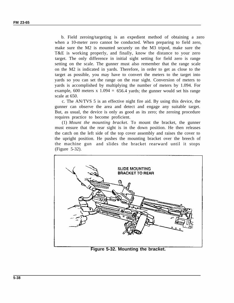
(1) Mount the mounting bracket. To mount the bracket, the gunnermust ensure that the rear sight is in the down position. He then releasesthe catch on the left side of the top cover assembly and raises the cover tothe upright position. He pushes the mounting bracket over the breech ofthe machine gun and slides the bracket rearward until it stops(Figure 5-32).
Figure 5-32. Mounting the bracket.
5-38
FM 23-65
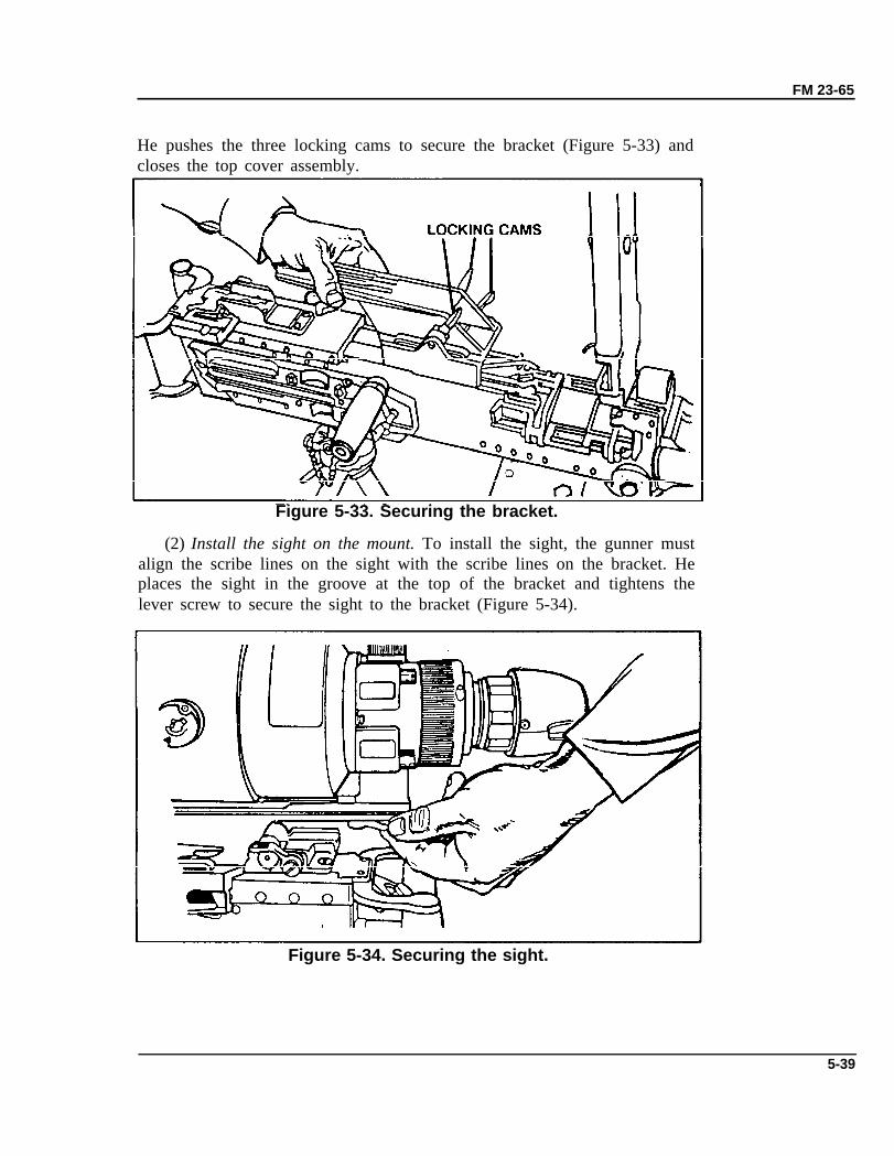
He pushes the three locking cams to secure the bracket (Figure 5-33) andcloses the top cover assembly.
Figure 5-33. Securing the bracket.
(2) Install the sight on the mount. To install the sight, the gunner mustalign the scribe lines on the sight with the scribe lines on the bracket. Heplaces the sight in the groove at the top of the bracket and tightens thelever screw to secure the sight to the bracket (Figure 5-34).
Figure 5-34. Securing the sight.
5-39
FM 23-65
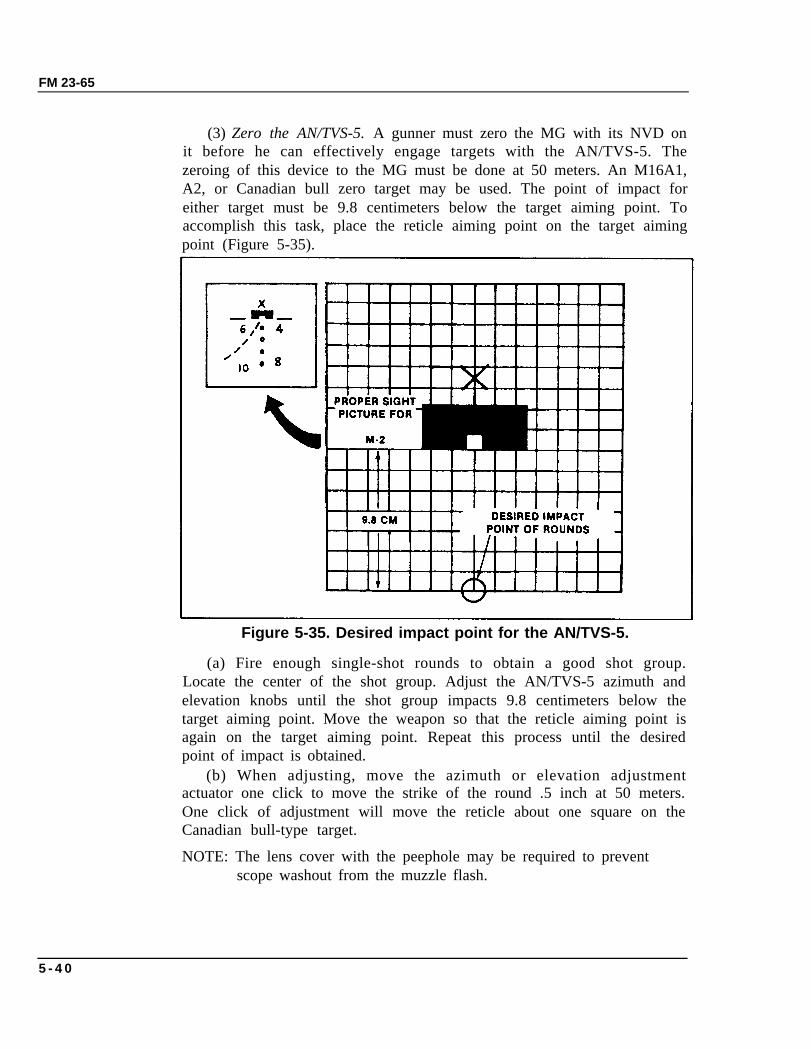
(3) Zero the AN/TVS-5. A gunner must zero the MG with its NVD onit before he can effectively engage targets with the AN/TVS-5. Thezeroing of this device to the MG must be done at 50 meters. An M16A1,A2, or Canadian bull zero target may be used. The point of impact foreither target must be 9.8 centimeters below the target aiming point. Toaccomplish this task, place the reticle aiming point on the target aimingpoint (Figure 5-35).
Figure 5-35. Desired impact point for the AN/TVS-5.
(a) Fire enough single-shot rounds to obtain a good shot group.Locate the center of the shot group. Adjust the AN/TVS-5 azimuth andelevation knobs until the shot group impacts 9.8 centimeters below thetarget aiming point. Move the weapon so that the reticle aiming point isagain on the target aiming point. Repeat this process until the desiredpoint of impact is obtained.
(b) When adjusting, move the azimuth or elevation adjustmentactuator one click to move the strike of the round .5 inch at 50 meters.One click of adjustment will move the reticle about one square on theCanadian bull-type target.
NOTE: The lens cover with the peephole may be required to preventscope washout from the muzzle flash.
5 - 4 0
FM 23-65
(4) Dismount the sight. The gunner dismounts the sight from thebracket first by loosening the lever screws. Then he lifts the sight from thebracket. He must then dismount the bracket in the reverse mountingprocedure.
5-14. TEN-METER FIRING EXERCISEThe purpose of 10-meter firing is to develop skills in the delivery of initialburst on target. When conducted properly, it will train gunners in the basicskills, such as 10-meter zero, controlled bursts, traverse, and traverse andsearch firing techniques. (See Appendix C for details on setup andconduct of firing.)
5-15. TRANSITION DAY FIRING EXERCISETransition day firing of the M2 machine gun will teach the gunner sometechniques of fire that he may encounter in combat situations. The gunnerwill field zero his weapon and engage point and area targets from thetripod-mounted firing position. Within this training, the gunner will berequired to apply all the fundamentals of gunnery learned in preparatorygunnery training and 10-meter firing. (See Appendix C for details on thesetup and conduct of transition day fire.)
5-16. NBC FIRINGSince NBC plays an important part in our preparation for war on themodern battlefield, it is important that each soldier is prepared toaccomplish the mission even if the area is contaminated and he must wearprotective gear. (See Appendix C for details on setup and conduct of fire.)
5-17. NIGHT FIRE EXERCISEThe night fire exercise gives the soldiers the practical application ofengaging targets using the AN/TVS-5 at night or during limited visibility.(See Appendix C for details on setup and conduct of fire.)
Section IV. ADVANCED GUNNERY
After firing 10-meter, day, NBC, and night, gunners need practice inapplying what they have learned. They also need experience in engagingtargets that depict realistic enemy formations. Advanced gunner exercisesprovide this experience in mounted, mounted NBC, and predeterminedfiring exercises.
5-41
FM 23-65
5-18. OBJECTIVESThe objectives of the advanced gunnery phase are to prepare the gunnersfor combat. During this phase, training should be directed toward –
• Tracking and leading.• Mounted target engagement techniques.• Mounted NBC engagements.• Predetermined fire techniques.
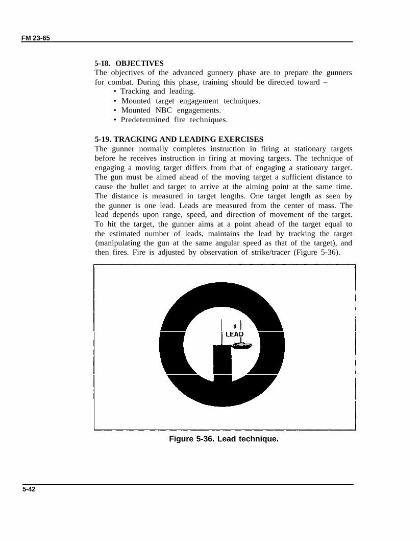
5-19. TRACKING AND LEADING EXERCISESThe gunner normally completes instruction in firing at stationary targetsbefore he receives instruction in firing at moving targets. The technique ofengaging a moving target differs from that of engaging a stationary target.The gun must be aimed ahead of the moving target a sufficient distance tocause the bullet and target to arrive at the aiming point at the same time.The distance is measured in target lengths. One target length as seen bythe gunner is one lead. Leads are measured from the center of mass. Thelead depends upon range, speed, and direction of movement of the target.To hit the target, the gunner aims at a point ahead of the target equal tothe estimated number of leads, maintains the lead by tracking the target(manipulating the gun at the same angular speed as that of the target), andthen fires. Fire is adjusted by observation of strike/tracer (Figure 5-36).
Figure 5-36. Lead technique.
5-42
FM 23-65
a. Tracking. Tracking consists of maintaining correct alignment of thesights (with or without a lead) on a moving target by moving the gun at thesame angular speed as that of the target.
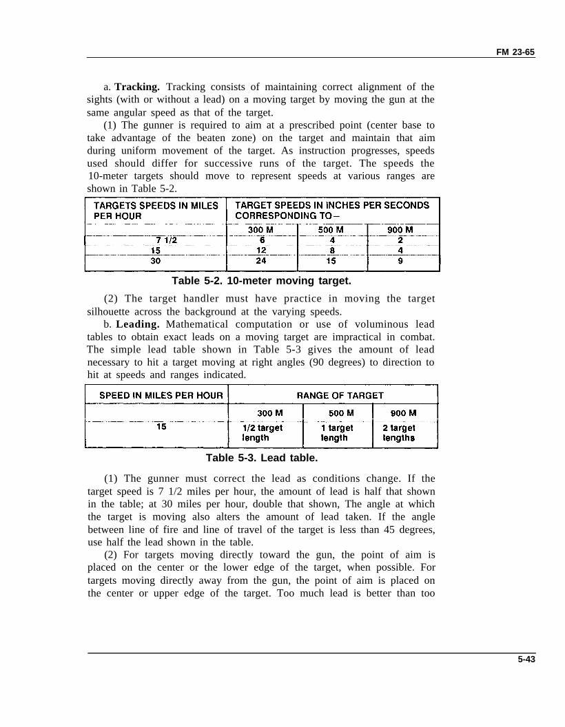
(1) The gunner is required to aim at a prescribed point (center base totake advantage of the beaten zone) on the target and maintain that aimduring uniform movement of the target. As instruction progresses, speedsused should differ for successive runs of the target. The speeds the10-meter targets should move to represent speeds at various ranges areshown in Table 5-2.
Table 5-2. 10-meter moving target.
(2) The target handler must have practice in moving the targetsilhouette across the background at the varying speeds.
b. Leading. Mathematical computation or use of voluminous leadtables to obtain exact leads on a moving target are impractical in combat.The simple lead table shown in Table 5-3 gives the amount of leadnecessary to hit a target moving at right angles (90 degrees) to direction tohit at speeds and ranges indicated.
Table 5-3. Lead table.
(1) The gunner must correct the lead as conditions change. If thetarget speed is 7 1/2 miles per hour, the amount of lead is half that shownin the table; at 30 miles per hour, double that shown, The angle at whichthe target is moving also alters the amount of lead taken. If the anglebetween line of fire and line of travel of the target is less than 45 degrees,use half the lead shown in the table.
(2) For targets moving directly toward the gun, the point of aim isplaced on the center or the lower edge of the target, when possible. Fortargets moving directly away from the gun, the point of aim is placed onthe center or upper edge of the target. Too much lead is better than too
5-43
FM 23-65
little because the target runs into the fire; also, the observation of strike iseasier. Intelligent use of the lead table includes immediate application offire with estimated lead followed by necessary corrections based uponobservation of strike/tracer.
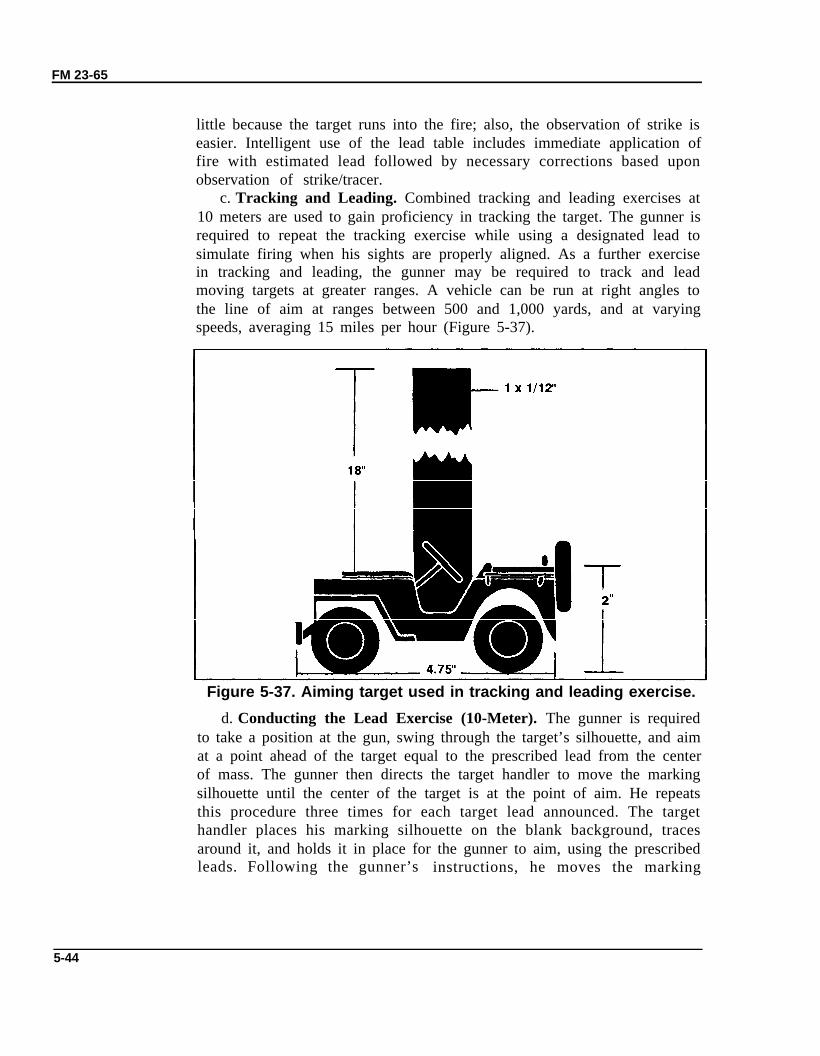
c. Tracking and Leading. Combined tracking and leading exercises at10 meters are used to gain proficiency in tracking the target. The gunner isrequired to repeat the tracking exercise while using a designated lead tosimulate firing when his sights are properly aligned. As a further exercisein tracking and leading, the gunner may be required to track and leadmoving targets at greater ranges. A vehicle can be run at right angles tothe line of aim at ranges between 500 and 1,000 yards, and at varyingspeeds, averaging 15 miles per hour (Figure 5-37).
Figure 5-37. Aiming target used in tracking and leading exercise.
d. Conducting the Lead Exercise (10-Meter). The gunner is requiredto take a position at the gun, swing through the target’s silhouette, and aimat a point ahead of the target equal to the prescribed lead from the centerof mass. The gunner then directs the target handler to move the markingsilhouette until the center of the target is at the point of aim. He repeatsthis procedure three times for each target lead announced. The targethandler places his marking silhouette on the blank background, tracesaround it, and holds it in place for the gunner to aim, using the prescribedleads. Following the gunner’s instructions, he moves the marking
5-44
FM 23-65
silhouette until the gunner commands HOLD. He then places a pencil dotat this point and returns the silhouette to the original position. Thisprocedure is followed until the gunner has completed three tries for eachtarget lead announced. The three pencil dots for each target should fitwithin a one-centimeter circle. The exercise should be conducted forvarying left and right leads.
5-20. MOUNTED FIRING EXERCISEThe purpose of the mounted firing exercise is to teach the gunnertechniques of firing the M2 MG from a mounted platform and to developthe gunner’s ability to fire the M2 with it mounted on its primary carrier.(See Appendix C for details on the setup and conduct of fire.)
5-21. MOUNTED NBC FIRING EXERCISEThe probability of fighting mounted in a tactical environment that hasbeen contaminated by NBC agents is very likely; therefore, gunners mustbe trained to engage targets while in a mounted NBC posture. (SeeAppendix C for details on the setup and conduct of fire.)
5-22. PREDETERMINED FIRING EXERCISEThe predetermined firing exercises are designed to instruct the gunners onpreparing and using range cards during any visibility conditions. (SeeAppendix C for details on setup and conduct of fire.)
5-45