Embed Size (px)
Citation preview

MARK 7® RELOADING REVOLUTION USER MANUAL VERSION 2.0, COPYRIGHT ALL RIGHTS RESERVED
1
Mark 7® Revolution
User Manual
v 2.0
Read this manual. Understand all safety and operating instructions. Failure to comply
with the warnings and instructions may result in serious injury, illness or death.

2 Mark 7® Reloading REVOLUTION User Manual version 2.0, Copyright
All rights reserved
Table of Contents
Table of Contents ......................................................................................................................................... 2
Important Safety Instructions ................................................................................................................... 3
Set-Up Procedures ........................................................................................................................................ 4
1. Package contents .................................................................................................................................. 4
2. Removal of equipment from Packaging ................................................................................................ 8
3. Case Feeder and Bullet Feeder Setup ................................................................................................... 9
4. Automated Priming Setup .................................................................................................................. 12
5. Tablet and Tablet Holder Setup .......................................................................................................... 14
6. Powder Measure ................................................................................................................................. 14
7. Console Side I/O inputs ....................................................................................................................... 18
8. Console Rear I/O inputs ...................................................................................................................... 19
10. Overall Machine Setup ..................................................................................................................... 20
11. Manully Driving the press ................................................................................................................ 21
12. Tool Head Recommended Die locations ........................................................................................... 22
Operating Instructions: Revolution ........................................................................................................... 23
Optical Decapping Sensor™ .................................................................................................................. .37
.......................................................................................................................... 39
………………….……………………………………………………………………..………………………42
........................................................................................................................ 44
Primer Orientation Sensor ………………………………………………………………………………………………………………………….53
Sofware Firmware Updates ....................................................................................................................... 60
Maintenance Intervals ............................................................................................................................... 61
Storage Recommendations ........................................................................................................................ 67
Reloading Manual ...................................................................................................................................... 67
Troubleshooting ....................................................................................................................................... 71

MARK 7® RELOADING REVOLUTION USER MANUAL VERSION 2.0, COPYRIGHT ALL RIGHTS RESERVED
3
Important Safety Instructions
Read this manual completely prior to installation and operation. Understand all safety and operating
instructions. Failure to comply with the WARNINGS and instructions may result in serious injury or death.
WARNINGS throughout this manual will be symbolized by the yellow WARNING symbols seen below.
WARNING – Activities using the Mark 7® RevolutionTM are inherently dangerous and may lead to injury
and even death. Actions as a result of using the Mark 7® product are solely the responsibility of the user
– if you get injured through the reloading process or through the use of ammunition as a result of the
reloading process it is your fault.
WARNING - Mark 7® equipment should only be operated by trained personnel that follow all safety
precautions. Failure to do so could result in serious injury or death.
WARNING - Never leave your Mark 7® RevolutionTM unattended while it is operating.
WARNING – Never operate the Mark 7® RevolutionTM while impaired.
WARNING – Never operate that Mark 7® RevolutionTM without using high quality brass and always use
sufficient lubrication on your brass while operating the Mark 7® RevolutionTM.
WARNING – The Mark 7® RevolutionTM is designed to automate the process of loading and processing of
ammunition. Never operate the Mark 7® RevolutionTM at speeds higher than you have tested and are
4 Mark 7® Reloading REVOLUTION User Manual version 2.0, Copyright
All rights reserved
comfortable with for the type of reloading or processing that you are undertaking. Run the Mark 7®
RevolutionTM at the slowest possible setting to create quality ammunition.
WARNING – Always wear protective eyewear to protect eyes from being injured. Flying debris may result
when using this equipment. Always wear protective clothing that covers arms, legs and neck to protect
from injury. It is the responsibility of the user to ensure that appropriate protective clothing and
equipment are used to provide protection from those hazards to which personnel are exposed or could
be exposed to while working with this product. Failure to do so could result in serious injury or death.
Setup Procedures
1.Packaging Contents
The Revolution is packaged on a single pallet containing a crate with the Revolution Main Unit and
separate corrugated boxes containing the press accessories.

MARK 7® RELOADING REVOLUTION USER MANUAL VERSION 2.0, COPYRIGHT ALL RIGHTS RESERVED
5
Press Accessories
Item No. Description QTY
Item No.
Description
QTY
1 Primer Controller Assembly 1 10 Filter 1
2 Primer Bowl Safety Shield Assembly 1 11 Micro SD Card 1
3 Primer Offload Hose 1 12 Micro SD Card Adapter 1
4 Shell Plate Retaining Spring 1 13 Fastener Mount Cable Tie Holder 4
5 Case Retaining Spring 1 14 Zip Tie 4
6 Tablet Holder 1 15 Motor 8-Pin Cable 1
7 Tablet 1 16 Motor 6-Pin Cable 1
8 Akro Bin 1 17 Tablet USB Cable 1
9 ½” Hex Wrench 1 1
1
2
3
4
5
7
8 9 10 11
1
13
12
15
6
16 14
17

6 Mark 7® Reloading REVOLUTION User Manual version 2.0, Copyright
All rights reserved
Digital Powder Measure
Item No. Description QTY
1 Digital Powder Measure Assembly 1
2 4-Pin Communication Cable 1
3 Power Cord 1
4 Powder Measure Electronics Assembly 1
5 Powder Funnel 1
14” Case Feeder
Item No. Description QTY
1 Case Feeder Output Switch Assembly 1
2 Case Feeder – 14” 1
3 Case Feeder Output Spring 1
4 Pole Top Mount – Case Feeder 1
5 Pole – Case Feeder/Bullet Feeder 1
6 Washer – ¼” Screw 4
7 Hex Head Rounded – ¼”-20 x 5/8” L 4
1
2
3
4
5
1
2
3
4 5
6 7

MARK 7® RELOADING REVOLUTION USER MANUAL VERSION 2.0, COPYRIGHT ALL RIGHTS RESERVED
7
Mr.BulletFeeder Pro
Item No. Description QTY
1 Mr. Bullet Feeder Pro 1
2 Socket Screw – 5/16” -18 x ¾” Long 1
3 Washer – 5/16” Screw 1
4 Pole Top Mount – Bullet Feeder 1
5 Pole – Case Feeder/Bullet Feeder 1
6 Washer – ¼” Screw 4
7 Hex Head – ¼”-20 x 5/8” Long 4
8 Mr. Bullet Feeder Pro Dropper 1
9 DAA – Expansion Funnel 1
10 DAA – Output Assembly 1
1
2
3
4
5
6 7
8
9
10

8 Mark 7® Reloading REVOLUTION User Manual version 2.0, Copyright
All rights reserved
2. Unpacking instructions:
The Revolution Main Unit is heavy. Please use caution when handling the Crate. Use 2 people to remove
the core machine from the Crate.
• Remove the lid off the crate by bending back the metal tabs on all four sides
• The Baseplate of the Revolution Main Unit is fastened to the base of the Crate with 4X Lag
Bolts in the corners.
• Use a ½” socket and extension to remove the bolts. Alternatively, the sides of the Crate can be
removed for easier access.
• Move the Revolution Main Unit onto the workbench or working surface using 2 people.
Figure 1: Lag bot locations
Lag location (4X)
Baseplate
(Revolution Main Unit)
Crate

MARK 7® RELOADING REVOLUTION USER MANUAL VERSION 2.0, COPYRIGHT ALL RIGHTS RESERVED
9
3. Case Feeder and Bullet Feeder Setup:
Assemble Case Feeder and Bullet Feeder poles to the base units.
Figure 2 Case Feeder and BulletFeeder Poles Installation.
• Assemble Pole Top Mount – BulletFeeder into Pole (BulletFeeder) using hardware in Figure 3.
• Assemble Mr. BulletFeeder PRO Assembly onto Pole top Mount -BulletFeeder using hardware
in Figure 3.
• Assemble Pole Top Mount – Case Feeder into Pole (Case Feeder) using hardware in Figure 3.
Case Feeder Base (Installed)
(
BulletFeeder Base (Installed)
(
Pole
(BulletFeeder)
Pole
(Case Feeder)
2X Washer, ¼” Screw
( 2X Hex Head Rounded- ¼”-20 x 5/8

10 Mark 7® Reloading REVOLUTION User Manual version 2.0, Copyright
All rights reserved
Figure 3: Case Feeder and BulletFeeder Collators Installation.
• Install Case Drop Tube into Case Feed Adapter. Pay attention to install o-ring end into
adapter.
• Install Case Feeder Output Switch Assembly into Case Drop Tube.
• Assemble Case Feeder Output Spring onto Case Feeder Output Switch Assembly and Case
Feeder – 14”.
• Connect Case Feeder – 14” to Case Feeder Output Switch Assembly.
Pole (Case Feeder)
Case Feeder – 14”
Pole Top Mount – Case Feeder
(Pistol version shown)
2X Washer, ¼” Screw
2X Hex Head Rounded- ¼”-20 x 5/8
Pole Top Mount - BulletFeeder
Mr. BulletFeeder PRO Assembly
Socket Head Screw –
5/16”-18 x 3/4”
-
MARK 7® RELOADING REVOLUTION USER MANUAL VERSION 2.0, COPYRIGHT ALL RIGHTS RESERVED
11
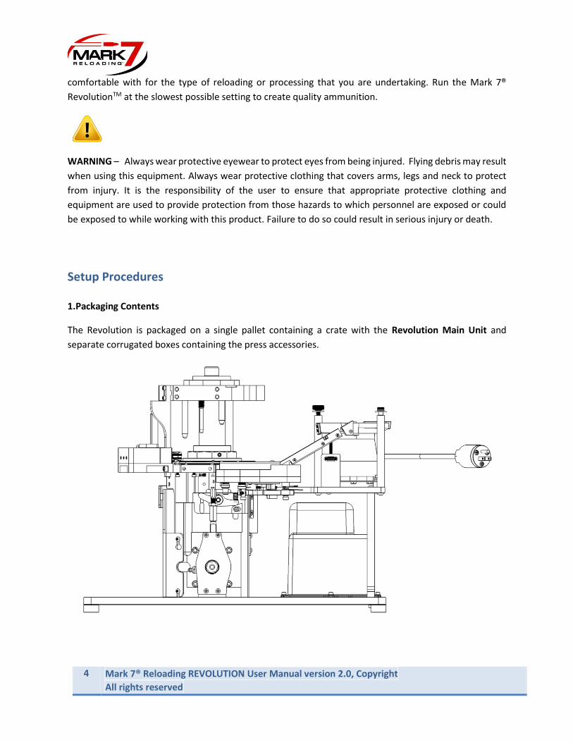
• Thread Mr. BulletFeeder Pro Dropper Assembly into Tool Head Station 8 (See Page 22)
• Assemble DAA-Output Assembly onto Mr. BulletFeeder Pro Dropper Assembly and Mr.
BulletFeeder Pro Assembly. Large adapter end installs onto dropper assembly and small
adapter end installs on Mr. BulletFeeder Pro Assembly.
Figure 4: Case feeder drop tube assembly and Bullet feeder installation.
Case Feed Adapter
Case Drop Tube
Case Feeder Output Switch Assembly
Case Feeder Output Spring
Case Feeder – 14”
Mr. BulletFeeder Pro Assembly
Mr. BulletFeeder Pro Dropper Assembly

12 Mark 7® Reloading REVOLUTION User Manual version 2.0, Copyright
All rights reserved
Connect Filter – BulletFeeder Cable Assembly to Mr. BulletFeeder Pro Dropper Assembly as shown in
Figure 5.
Figure 5: Filter-BulletFeeder Cable Assembly Installation
4. Automated Priming System Setup
The automatic priming system uses an independent vibratory controller to power the priming motor.
• Plug the Priming Motor Power Cord into the Controller Power Cord Port.
• Connect the Primer Call Sensor Cable to the Low Primer Sensor Cable installed on the Revolution Main unit (See Figure 7.) The Controller has an On/Off Switch and a Dial that controls the vibration frequency.
Figure 6: Priming Controller
Primer Call Sensor Cable Primer Motor Power Cord
Port
Dial
Mr. BulletFeeder Pro – Red Cable
Mr. BulletFeeder Pro – Black Cable
Power Cord Controller

MARK 7® RELOADING REVOLUTION USER MANUAL VERSION 2.0, COPYRIGHT ALL RIGHTS RESERVED
13
Install Primer Bowl Shield Assembly onto Revolution Main Unit. Attach using hardware per Figure 7.
Knob
Screw
Spring
Washer
O-ring
Safety Shield
Shoulder Screw
Washer
Connect to Primer
Motor Cord Port
Low Primer Sensor
Cable
Figure 7: Safety Shield Installation

14 Mark 7® Reloading REVOLUTION User Manual version 2.0, Copyright
All rights reserved
5. Mount Tablet and Holder
• Install Tablet Holder onto Case Feeder Pole.
• Install Tablet into Tablet Holder.
Figure 8: Tablet and Holder
• Insert Tablet USB Cable into USB port on Tablet and into port on Revolution Main Unit
console labeled “Micro USB.”
• Insert Revolution Main Unit Tablet Power Supply Cable into power port on Tablet
adjacent to the Micro USB cord.
6. Powder Measure
Install Powder Funnel into Powder Measure Lower. Pistol uses a universal funnel, Rifle powder
measures come with both a SM rifle and LG rifle funnels.
Tablet Holder
Tablet
MARK 7® RELOADING REVOLUTION USER MANUAL VERSION 2.0, COPYRIGHT ALL RIGHTS RESERVED
15
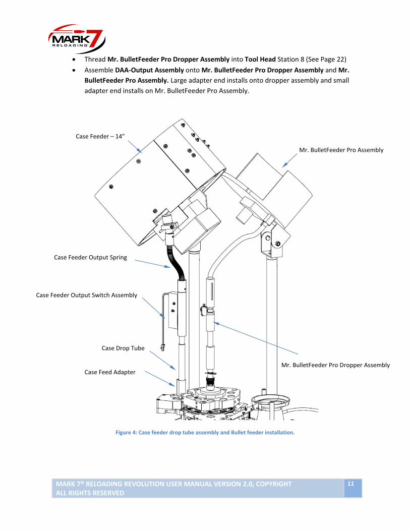
The Powder Measure Assy is shipped with the Powder Hopper removed from the Powder Measure
Upper. Initial assembly is required.
Loosen C-Clip on Powder Measure Upper. Rotate Clip to clear Powder Hopper interface hole and install
Powder Hopper. Rotate C-Clip over Powder Hopper Funnel Flange and tighten screws.
Install assembled Digital Powder Measure Assembly into Tool Head station 6. (See Figure 12.)
C-Clip
Tighten
Screws
Powder Hopper
Powder Measure Upper
Figure 9: Powder Hopper Installation
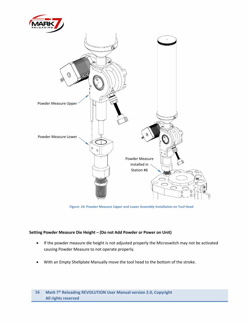
16 Mark 7® Reloading REVOLUTION User Manual version 2.0, Copyright
All rights reserved
Figure: 10: Powder Measure Upper and Lower Assembly Installation on Tool Head
Setting Powder Measure Die Height – (Do not Add Powder or Power on Unit)
• If the powder measure die height is not adjusted properly the Microswitch may not be activated
causing Powder Measure to not operate properly.
• With an Empty Shellplate Manually move the tool head to the bottom of the stroke.
Powder Measure
installed in
Station #6
Powder Measure Lower
Powder Measure Upper

MARK 7® RELOADING REVOLUTION USER MANUAL VERSION 2.0, COPYRIGHT ALL RIGHTS RESERVED
17
Thread the die down far enough so that you can just move the funnel 1/16” of an inch before the
Powder Measure Uppers starts to separate from the lower assembly. Then check the height with a case
under station #6 to ensure the microswitch is activated and the upper and lower separation is 3/8” to
½”.
Gap
3/8” to ½”
Microswitch
Set Screw
Lock Nut
Empty case
Figure 11: Powder Measure Die Setup and Adjustment

18 Mark 7® Reloading REVOLUTION User Manual version 2.0, Copyright
All rights reserved
7. Console side I/O Inputs:
Figure 12: Console Side Ports
Before powering on the Machine please make the following connections:
Micro-USB: Tablet to Console USB data communication cable**Must have correct orientation if the
cable has a short adapter and then a long piece. The short side must plug into the tablet for the
accept/deny buttons to appear**!
USB-A: Motor to Console USB data communication cable (plugs into Back of motor)
8-Pin Motor: Motor to console signal cable (Plugs into top of motor)
Port #7: Digital Powder Measure Communication Cable
Port #6: Wired Remote Stop (optional Sensor)
Port #5: DecapSense™ (Optional Sensor)

MARK 7® RELOADING REVOLUTION USER MANUAL VERSION 2.0, COPYRIGHT ALL RIGHTS RESERVED
19
8. Console Rear I/O Inputs:
Figure 13: Console Rear Ports
Port #4: Digital Powder Check Sensor (optional)
Port #3: (Optional)
Port #2: Primer Orientation Sensor (Optional)
Port #1: (Optional)
AC INPUT & ON/OFF: Units are configured in either 110V or 220V.
MOTOR 6-PIN: Motor to Console DC Power Cord (Plugs into top of motor)
TABLED DC: Connect cord to tablet
20 Mark 7® Reloading REVOLUTION User Manual version 2.0, Copyright
All rights reserved
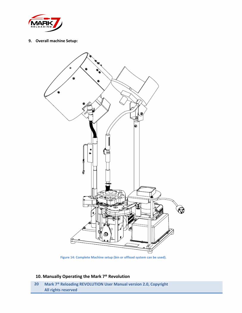
9. Overall machine Setup:
10. Manually Operating the Mark 7® Revolution
Figure 14: Complete Machine setup (bin or offload system can be used).
MARK 7® RELOADING REVOLUTION USER MANUAL VERSION 2.0, COPYRIGHT ALL RIGHTS RESERVED
21
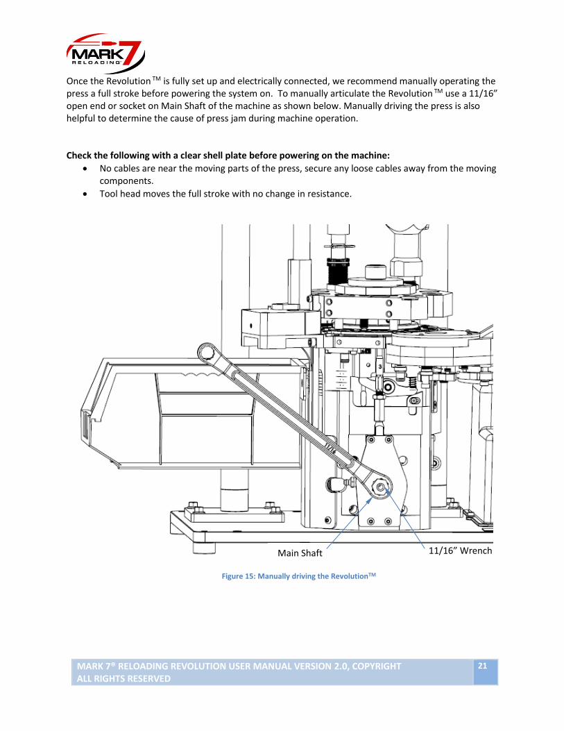
Once the Revolution TM is fully set up and electrically connected, we recommend manually operating the press a full stroke before powering the system on. To manually articulate the Revolution TM use a 11/16” open end or socket on Main Shaft of the machine as shown below. Manually driving the press is also helpful to determine the cause of press jam during machine operation. Check the following with a clear shell plate before powering on the machine:
• No cables are near the moving parts of the press, secure any loose cables away from the moving components.
• Tool head moves the full stroke with no change in resistance.
Figure 15: Manually driving the RevolutionTM
Main Shaft
11/16” Wrench
22 Mark 7® Reloading REVOLUTION User Manual version 2.0, Copyright
All rights reserved
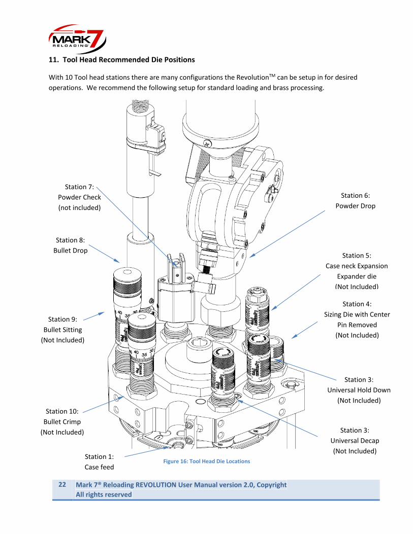
11. Tool Head Recommended Die Positions
With 10 Tool head stations there are many configurations the RevolutionTM can be setup in for desired
operations. We recommend the following setup for standard loading and brass processing.
Figure 16: Tool Head Die Locations Station 1:
Case feed
Station 3:
Universal Hold Down
(Not Included)
Station 4:
Sizing Die with Center
Pin Removed
(Not Included)
Station 5:
Case neck Expansion
Expander die
(Not Included)
Station 6:
Powder Drop
Station 7:
Powder Check
(not included)
Station 8:
Bullet Drop
Station 9:
Bullet Sitting
(Not Included)
Station 10:
Bullet Crimp
(Not Included)
Station 3:
Universal Decap
(Not Included)

MARK 7® RELOADING REVOLUTION USER MANUAL VERSION 2.0, COPYRIGHT ALL RIGHTS RESERVED
23
Operating Instructions
Once the machine is fully assembled and setup, we recommend the following steps to configure the press
for operation.
• Determine intended use of machine (processing, loading, processing/loading combined and setup
press accordingly – please feel free to contact us to discuss your requirements.
• Thread the dies into Tool Head but do not set final adjustments at this time – keep dies partially
backed off.
• Cycle the machine a few times manually without components to ensure smooth operation and is
indexing properly.
1. Case feed - sizing/decapping – Station 1 and 2
Add cases to the Case feeder in the caliber that you are loading. Run cases around the shell plate to
ensure proper feeding. Install the Akro bin provided with the press as the case offload or attach the
optional offload system.
Remove the cases from the shell plate and move the Tool head to the down position. Thread the sizing
die all the way down so that it just starts to touch the shell plate and lock the die in place. Connect the
decapping hose. Always use case lube when re-sizing once fired cases. Run a few cases through the sizing
die and check cases using a sizing gauge to confirm they are being fully sized and decapped properly.
2. Swage Setup– Station 3
The Revolution ™ is shipped with the swage rod fully backed off in the down position. We recommend to
cut an empty case in half (cross-section) and insert it into the shell plate in station 3. Always use a hold
down die over the swaging station and never run the machine without the tool head on to avoid damaging
the swage during a jam.
• Move the Tool head to the bottom.
• Lower a swage back up die until the center contacts the bottom of the case. Lower a ¼ turn and
lock down.
• Raise the swage rod until the swage rod enters the primer pocket and the shoulder contacts the
bottom of the case. Turn ¼ more and lock in place.
• Remove the case used to adjust the rods and install a case that has been previously decapped.
• Perform a cycle with the case in station 3 -then remove and inspect the primer pocket to
confirm that the pocket is swaged properly. Adjust as needed.
• We recommend using a primer pocket gauge especially if uses crimped/military brass.

24 Mark 7® Reloading REVOLUTION User Manual version 2.0, Copyright
All rights reserved
3. Primer Seating- Station 4
The RevolutionTM comes standard with an automated priming system. Primers can be filled directly into
the primer bowl assembly. Before adding primers its important to power on the vibratory unit and make
sure the bowl is adjusted properly.
The Primer Bowl must not contact any rigid parts of the machine or the vibration will be dampened. It is
important that there is a gap between the Primer bowl and the Priming ramp. There are 3 adjustment
points in the primer system:
• Adjustment 1: Ramp Height – Thumb Nut
• Adjustment 2: Bowl Rotation - Screw
Adjustment 3: Motor Position – (4X) Lock Nuts
The adjustment is pre-set in the factory, however due to shipping and press vibrations over time the
priming system may need to be adjusted as needed to ensure proper feeding.
Figure 17: Primer Motor/Bowl Adjustments (Shield Removed for Clarity)
Adjustment 2
Adjustment 3
Adjustment 1
Gap (Required)
Primer Ramp

MARK 7® RELOADING REVOLUTION USER MANUAL VERSION 2.0, COPYRIGHT ALL RIGHTS RESERVED
25
WARNING – Never overfill the primer bowl. Always wear safety glasses and hearing
protection when handling primers
We recommend the following when setting up the priming system:
• Fill up the bowl with a single pack of 100 primers.
• Turn on the vibratory motor with the controller set at the lowest setting (0). Gently increase the
vibratory motor until the primer start to move up the ramp. Adjust the bowl as necessary until
the primers fall down the ramp into the disk assembly.
• Cycle the press without a case present to ensure proper primer feeding into the disk assembly
• Pause with the Tool Head in the down position and verify that the primer punch is inserted in
the shellplate with a primer.
• Place a case that has been decapped and has a verified primer pocket
• Cycle the press manually – there will be some resistance as you get to the bottom of the stoke –
use caution. Remove the case and check primer insertion depth.
• Adjust the primer insertion pin until the proper primer depth is achieved.
• Primers can either be recirculated or offloaded into a clear hose if a case isn’t present. There
are knurled brass adapters threaded into the bottom of the assembly
There are 2 primer Punch adjustments on the RevolutionTM press – refer to Figure 17.
1. Primer Depth – This adjusts the primer insertion depth – Never adjust more than a ¼ of a
turn without checking new depth.
2. Primer Punch lower height – This adjustment sets the height of the punch when the primer
is fully retracted. It should flush with the bushing in the primer housing.
A sizing die with the center removed can be used to hold down the cases in station 4 in order to provide
additional support to the cases during primer insertion.
WARNING – Never install more than 100 Primers at once. Always wear protective eyewear and hearing
protection when loading primers into the machine and loading. Activities using the Mark 7® EvolutionTM
are inherently dangerous and may lead to injury and even death.

26 Mark 7® Reloading REVOLUTION User Manual version 2.0, Copyright
All rights reserved
Figure 18: Primer Adjustments.
4. Case Neck expansion – Station 5
The RevolutionTM uses a dedicated station for neck expansion/flare in Station 5. For pistol calibers we
recommend using a Lee Universal Expander die with the Double Alpha expander powder funnel installed.
For rifle there are several 3rd party expansions dies that can be used including the Lee Universal Flaring
die with the rifle insert. We recommend doing an initial setup at this point to achieve just enough flare
for the bullet to fit inside the case mouth. The final adjustment is best to be dialed in later during the
bullet drop setup.
# 2
# 1
MARK 7® RELOADING REVOLUTION USER MANUAL VERSION 2.0, COPYRIGHT ALL RIGHTS RESERVED
27
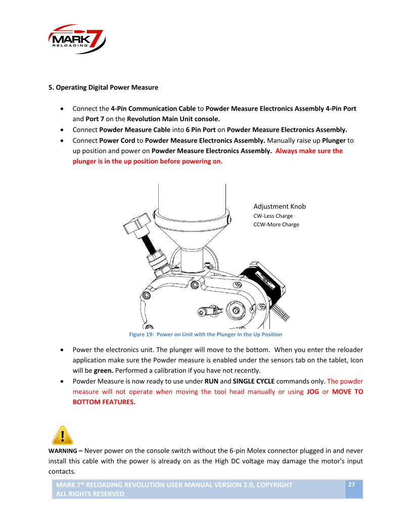
5. Operating Digital Power Measure
• Connect the 4-Pin Communication Cable to Powder Measure Electronics Assembly 4-Pin Port
and Port 7 on the Revolution Main Unit console.
• Connect Powder Measure Cable into 6 Pin Port on Powder Measure Electronics Assembly.
• Connect Power Cord to Powder Measure Electronics Assembly. Manually raise up Plunger to
up position and power on Powder Measure Electronics Assembly. Always make sure the
plunger is in the up position before powering on.
Figure 19: Power on Unit with the Plunger in the Up Position
• Power the electronics unit. The plunger will move to the bottom. When you enter the reloader
application make sure the Powder measure is enabled under the sensors tab on the tablet, Icon
will be green. Performed a calibration if you have not recently.
• Powder Measure is now ready to use under RUN and SINGLE CYCLE commands only. The powder
measure will not operate when moving the tool head manually or using JOG or MOVE TO
BOTTOM FEATURES.
WARNING – Never power on the console switch without the 6-pin Molex connector plugged in and never
install this cable with the power is already on as the High DC voltage may damage the motor's input
contacts.
Adjustment Knob CW-Less Charge
CCW-More Charge
C

28 Mark 7® Reloading REVOLUTION User Manual version 2.0, Copyright
All rights reserved
To set up charge:
The powder charge can be set manually (with the powder measure turned off) by operating the drum
control knob by hand. Or it can set powered by performing single cycles. For the powder measure to
operate, the machine must be powered, calibrated and power measure enabled on the sensor tab.
• Place a pre-primed case in station 6, under the Powder Measure.
• Perform a single press cycle to actuate the Powder Measure.
• Remove the case and weigh the charge.
• Empty the case and adjust the charge to the desired level by turning the adjustment knob.
Turning clockwise will decrease the charge, counterclockwise will increase the charge. Secure
plunger every time you changed the charge using Lock Nut
Once the desired charge is achieved perform a few dumps using “single cycle” on the Tablet. Perform
dump on the RPH setting you will be reloading. The charge is speed dependent. We recommend a
minimum of 5 drops to make sure the charge is consistent. Note: Always discard the first powder dump
after making an adjustment.
• Check the die nut and adjustment charge nut for tightness. Also, check the belt tension and
ensure the small sprocket is tight on the shaft.
• Move Selector switch to correct position based on caliber:
Warning - Before filling the Powder Hopper with Powder. Make sure the Powder Adjustment Knob is
adjusted all the way in (clockwise) for a minimum charge and verify. Each turn of the knob is approx. 1
grain.)
2 Stage is for LG Rifle – the arm will go up
and perform a half actuation and then
dump.
3 Stage is for pistol and SM Rifle – the arm
will go up halfway stop and then perform a
double dump.
MARK 7® RELOADING REVOLUTION USER MANUAL VERSION 2.0, COPYRIGHT ALL RIGHTS RESERVED
29
5. Setting up Mr.Bulletfeeder and Bullet Drop Assy – Station 8
There a few adjustments that are critical on the Mr.bulletfeeder to ensure that it’s operating properly,
further detail on this is located in the Mr.bulletfeeder user manual. We recommend removing the
Mr.bulletfeeder spring and running the bullets into a bucket while making the bowl adjustments until the
proper adjustments are achieved. The spring tube assembly may need to be cut between the dropper
and the drop tube assembly to the correct length for your setup – This is largely dependent on where the
feeder is mounted on the case feeder.
There is a delicate interaction between the bullet dropper and the amount of brass flair provided by
expander die for pistol. Setting the right amount of flare is critical to reduce bullet topple and to ensure
proper bullet seating with every cycle. The expansion die should open the case mouth just enough for the
bullet to slip in – the bullet dropper will provide a slight amount of pressure which will keep the bullet in
place.
A way to check a properly adjusted is to remove a round from the Shell Plate after the bullet has been
dropped (but not yet seated) and turn the case upside down. If the bullet falls out of the case there is
likely too much flare.
Adjust the bulletfeeder drop tube assembly so that a single bullet drops when it encounters a case. If
more than one bullet drops, it’s likely the drop tube assembly is adjusted too low in the Tool Head.
7. Bullet Seating / Crimping Setup – Station 9 & 10
The OAL and crimp can be set in station 9 and station 10. It’s always best to set these adjustments with a
fully loaded shell plate. Run a few rounds through until consistent OAL are achieved. The station 10
Spring retaining clamp retains the round in station 10 – to remove a casing slightly advance the shell plate
a few degrees remove the case then move it back into position.

30 Mark 7® Reloading REVOLUTION User Manual version 2.0, Copyright
All rights reserved
WARNING - This equipment uses a high-torque motor and drive crank system. Avoid contact
with any part of the drive mechanism. Contact with any of the drive components could result in serious
injury or death.
Main Screen
Figure 20: Tablet Home Screen
When the tablet is powered on the main screen shown above will launch. This screen contains the
Reloader, firmware and software applications. Before selecting the Reloader application, make sure the
console is powered on, all system cables are connected, and the shell plate is clear.
MARK 7® RELOADING REVOLUTION USER MANUAL VERSION 2.0, COPYRIGHT ALL RIGHTS RESERVED
31
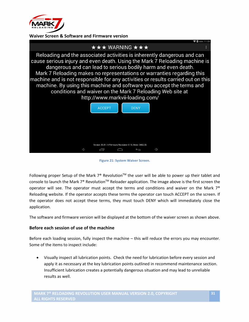
Waiver Screen & Software and Firmware version
Figure 21: System Waiver Screen.
Following proper Setup of the Mark 7® RevolutionTM the user will be able to power up their tablet and
console to launch the Mark 7® RevolutionTM Reloader application. The image above is the first screen the
operator will see. The operator must accept the terms and conditions and waiver on the Mark 7®
Reloading website. If the operator accepts these terms the operator can touch ACCEPT on the screen. If
the operator does not accept these terms, they must touch DENY which will immediately close the
application.
The software and firmware version will be displayed at the bottom of the waiver screen as shown above.
Before each session of use of the machine
Before each loading session, fully inspect the machine – this will reduce the errors you may encounter.
Some of the items to inspect include:
• Visually inspect all lubrication points. Check the need for lubrication before every session and
apply it as necessary at the key lubrication points outlined in recommend maintenance section.
Insufficient lubrication creates a potentially dangerous situation and may lead to unreliable
results as well.

32 Mark 7® Reloading REVOLUTION User Manual version 2.0, Copyright
All rights reserved
Control Screen
Figure 22: System Control Screen.
CALIBRATE - The function is the first operation that must be performed before fully running the Mark 7®
RevolutionTM. CALIBRATE signals the Motor to find the top and bottom of the presses stroke. Once
calibration is completed all functions on the control screen can be used. The shell plate must be clear
when calibrating. Calibration takes approximately 10 seconds to complete.
SPEED (Rounds Per Hour) – After Calibration is completed you may select the speed in which to operate
the machine. These can also be changed on the fly while the press is in motion. There are 6 speeds ranging
from 1000-3500 RPH.
DIGITAL CLUTCH - The Digital Clutch setting is the way in which the operator controls the torque output
of the motor. We recommend keeping the digital clutch at the lowest level required to complete a desired
action, whether it is re-sizing, or making complete ammunition. When the operator hits the torque limit
the Mark 7® RevolutionTM will stop and notify you. To continue operating check for a jam/obstruction if
not detected increase the digital clutch value and hit RUN until the cycle is completed.

MARK 7® RELOADING REVOLUTION USER MANUAL VERSION 2.0, COPYRIGHT ALL RIGHTS RESERVED
33
When enabled TorqueSense® varies the motor torque throughout the
Stroke, dropping the torque primarily on the upstroke to a minimum baseline level. This increases the
machines sensitivity if a jam occurs in the upstroke due to a case feed or shell plate indexing issue. There
may be some instances when TorqueSense® will need to be disabled so the motor torque on the upstroke
can be increased via the digital clutch, such as if the system torques out half-way through sizing a rifle
case. If the TorqueSense torque limit is exceeded the machine will stop and notify you on the tablet.
TorqueSense® can be enabled or disabled by pressing the TorqueSense® icon.
RUN - The RUN function signals the Mark 7® RevolutionTM to begin operation at the settings requested.
ROUNDS PER HOUR - The speed settings options under ROUNDS PER HOUR give the operator the ability
to choose their desired cycle speed.
CLEAR SHELL PLATE - The CLEAR SHELL PLATE command will lower the tool head just enough so the shell
plate can be rotated to clear the brass at any point during loading. This command will only work with the
press in the HOME position at the top of the stoke.
SINGLE CYCLE - The SINGLE CYCLE function allows the operator to run a single cycle. This command will
only work when the press is stopped and in the top position.
END CYCLE - The END CYCLE function will complete the current cycle and return to the top position.
JOG UP - The JOG UP function will incrementally move the press upwards. The JOG UP function is useful
for clearing jams that may occur. The JOG UP function will only work when the press is at a stop.
JOG DOWN - The JOG DOWN function will incrementally move the press downwards. The JOG DOWN
function will only work when the press is at a stop.
STOP - The STOP function will stop the press from moving in any event. When pressed you have the option
to put the motor in neutral (to manually operate) or to clear the notification and continue running.

34 Mark 7® Reloading REVOLUTION User Manual version 2.0, Copyright
All rights reserved
Monitors Screen
Figure 23: System Monitor Screen.
SET PRIMER - The operator has the ability to set the number of primers used before the Mark 7®
RevolutionTM ends its current run.
SET BRASS - The operator has the ability to set the number of brass used before the Mark 7® RevolutionTM
ends its current run.
SET BULLET - The operator has the ability to set the number of bullets used before the Mark 7®
RevolutionTM ends its current run.
DISABLE COUNT - The DISABLE COUNT function gives the operator the ability to not count the number of
rounds made.
RESET - the RESET function allows the user to reset the ROUNDS MADE and ROUNDS PER HOUR fields.
RUN, END CYCLE, and STOP functions have the same functionality on the Monitors Screen as they do on
the Control Screen.
MARK 7® RELOADING REVOLUTION USER MANUAL VERSION 2.0, COPYRIGHT ALL RIGHTS RESERVED
35
The buttons underneath the screen either state – STOP at XX or Stop at Ignored. If the latter, the machine
will not stop – the monitor is not in use. If the former, the value that you set is the value that the machine
will stop on. If you set primers to 100 and the stop at value of 10, then the machine will stop when it has
reached 10 primers left (a value of 90 rounds made).
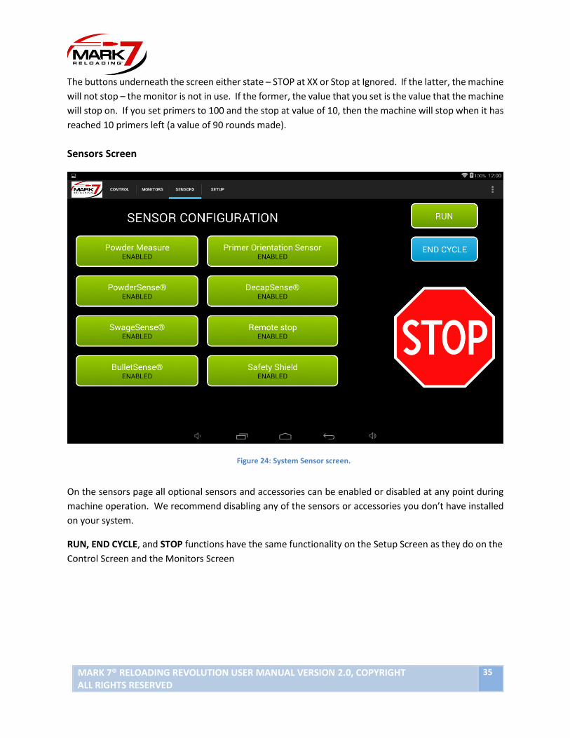
Sensors Screen
Figure 24: System Sensor screen.
On the sensors page all optional sensors and accessories can be enabled or disabled at any point during
machine operation. We recommend disabling any of the sensors or accessories you don’t have installed
on your system.
RUN, END CYCLE, and STOP functions have the same functionality on the Setup Screen as they do on the
Control Screen and the Monitors Screen

36 Mark 7® Reloading REVOLUTION User Manual version 2.0, Copyright
All rights reserved
Setup Screen
Figure 25: System Setup screen.
INDEX SPEED - The INDEX SPEED function allows the operator the ability to incrementally reduce the index
speed of the shell plate. The higher the value in the INDEX SPEED field the slower the shell plate will index.
TOP DWELL – The TOP DWELL function allows the operator the ability to add a slight pause at the top of
the stroke. This allows for a little extra time for the cases to fully settle before the tool head comes down.
BOTTOM DWELL - The BOTTOM DWELL function allows the operator the ability to increase the time in
which the press remains at the bottom of the stroke. The higher the value in the BOTTOM DWELL field
the longer the press remains at the bottom of the stroke.
MOVE TO B0TTOM - This command will move the press head to the bottom of the stroke which is helpful
for setting up the dies and adding powder.
RUN, END CYCLE, and STOP functions have the same functionality on the Setup Screen as they do on the
Control Screen and the Monitors Scree

MARK 7® RELOADING REVOLUTION USER MANUAL VERSION 2.0, COPYRIGHT ALL RIGHTS RESERVED
37
DECAPsense™ Operating Instructions
1. Remove the decap mount underneath station #2 and install the optical decapping sensor in the
orientation shown below.
1. Figure 26: Decapsense installed10
2. Hook up the 3/8” Clear Tube to the bottom the DECAPsense to catch spent primers
3. Calibrate and run the machine as normal. On the “Sensors tab,” make sure DECAPSense® is
enabled (Highlighted Green.) See Figure #3. When a spent primer is not ejected the following
notification box will appear:
DECAPSense

38 Mark 7® Reloading REVOLUTION User Manual version 2.0, Copyright
All rights reserved
After you rectify the issue press “Ok” and proceed with normal operation. As with all sensors the
DecapSense can be enabled or disabled on the Sensors Tab screen.
During operation the optical sensor may become dirty and require cleaning. The following notification box
MAY appear when cleaning is required:
Remove the case in station #2. Use an air can or compressed air and blast air down through the shell
plate and thru the sensor.
WARNING – Cleaning intervals of the Mark 7® DecapSense™ will vary dramatically based upon many
factors. We suggest cleaning the Mark 7® DecapSense™ as often as practical – It is up to you to ensure
that the sensor is clean.
This is a product that is designed to improve the safety of the reloading operation. Never rely on the
DecapSense alone. You must monitor its use – Always. Be close to your machine and available to stop
the machine if it needs to be stopped.

MARK 7® RELOADING REVOLUTION USER MANUAL VERSION 2.0, COPYRIGHT ALL RIGHTS RESERVED
39
SwageSense® Setup
1. Back off the Swage back-up expander die and swage rod off a few threads and insert a de-capped
case into station #3. Move the press head to the bottom position. Adjust the swage back-up
expander so it bottoms out against the bottom of the case and lock down the die. Next using
5/16 wrench thread the swage rod up until it bottoms out into the case pocket. Then turn it a ¼
turn more and lock down the jam nut. See the figure below.
Figure 1: Cross-section of properly adjusted Swage Rod.
2. The Microswitch is pre-adjusted so it will be triggered immediately when the SwageSense®
assembly starts to close. If you want to change the engagement of the switch use a .05” Allen Key
and a ¼” open end wrench. We do not recommend adjusting the setting unless it becomes out
of adjustment. To adjust tighten the Set Screw until you hear the switch trigger, then back it off
a ¼ turn and lock down with the Jam Nut.
Shell Plate
Swage Rod
Case
Hold Down Die Rod

40 Mark 7® Reloading REVOLUTION User Manual version 2.0, Copyright
All rights reserved
Figure 2: Microswitch Adjustment.
3. When the SwageSense® switch is triggered the following notification will appear on the reloader
application.
Figure 3: SwageSense® Notification.
Set Screw
use .05” Allen Key
to adjust
Jam Nut
use ¼” Wrench
to secure
Microswitch

MARK 7® RELOADING REVOLUTION USER MANUAL VERSION 2.0, COPYRIGHT ALL RIGHTS RESERVED
41
Increasing SwageSense Force
1. The swage force on SwageSense is adjustable from very sensitive (SM pistol) to full lockout
(military Crimp).
2. The Gap between the upper and lower housings determines the pre-load force on the assembly.
To adjust the gap first start by loosening the two Jam Set Screws on the top of the Housing.
3. Then adjust the Shoulder Screws on the bottom of the housing to set the desired force. The gap
working range is from .075-.095”. Never operate SwageSense out of this range. Whenever the
gap is adjusted the Microswitch will also need to be adjusted. Lastly lock down the Shoulder
Screws with the ¼”-20 Jam Set Screws.
4. We recommend starting with a gap of .095”. Then adjust the Microswitch Set Screw so it is just
starting to depress the Microswitch. Start with this value, by tightening the Shoulder Screws
you will add more pre-load to the screws which increases the swage force, but makes the ringer
detection less sensitive.
5. Tighten the Shoulder Screws evenly until desired gap is reached. Tighten two Jam Set Screws.
Figure 4: Adding set screws to lock shoulder screws in place.
Jam Set Screw
Jam Set Screw
Gap: .075” - .095”
Microswitch
Microswitch Set Screw
Shoulder Screws

42 Mark 7® Reloading REVOLUTION User Manual version 2.0, Copyright
All rights reserved
BulletSense® Installation Packaging Content:
Item No. Description QTY
1 BulletSense Mirror Mount Assy - EVO/Rev 1
2 BulletSense Sensor Head Assy 1
3 BulletSense Mount Assy - EVO/Rev 1
4 #8 Washer, 0.172" ID, 0.375" OD 2
5 Thumb Screw Brass 1
6 8-32 Thread Size, 3/8" Long Socket Cap Screw 1
7 Socket Head Screw, 1/4"-20 Thread Size x 3/4" Long 2
8 Socket Head Screw, 1/4"-20 Thread Size x 1-3/4" Long 1
9 Socket Head Screw, 1/4"-20 Thread Size x 1-1/2" Long 1
10 BulletSense Mirror Bracket Shim 1
1 2
3
4
5 6
7
8 9
10

MARK 7® RELOADING REVOLUTION USER MANUAL VERSION 2.0, COPYRIGHT ALL RIGHTS RESERVED
43
Set up Procedures:
1. Power Off Revolution Main Unit and remove indicated Screw from Revolution Main unit.
2. Install the BulletSense Mirror Mount onto Revolution Main Unit using hardware below.
(*Note: If loading rifle caliber, install BulletSense Mirror Bracket Shim in between BulletSense
Mirror Mount and Revolution Main Unit.)
Figure 5: BulletSense® installation.
*BulletSense Mirror
Bracket Shim* Use
with Rifle
Screw:
¼”-20 X 1 ½” Long w/o shim
¼”-20 1 ¾” Long w/shim
Screw
Mirror Mount
44 Mark 7® Reloading REVOLUTION User Manual version 2.0, Copyright
All rights reserved
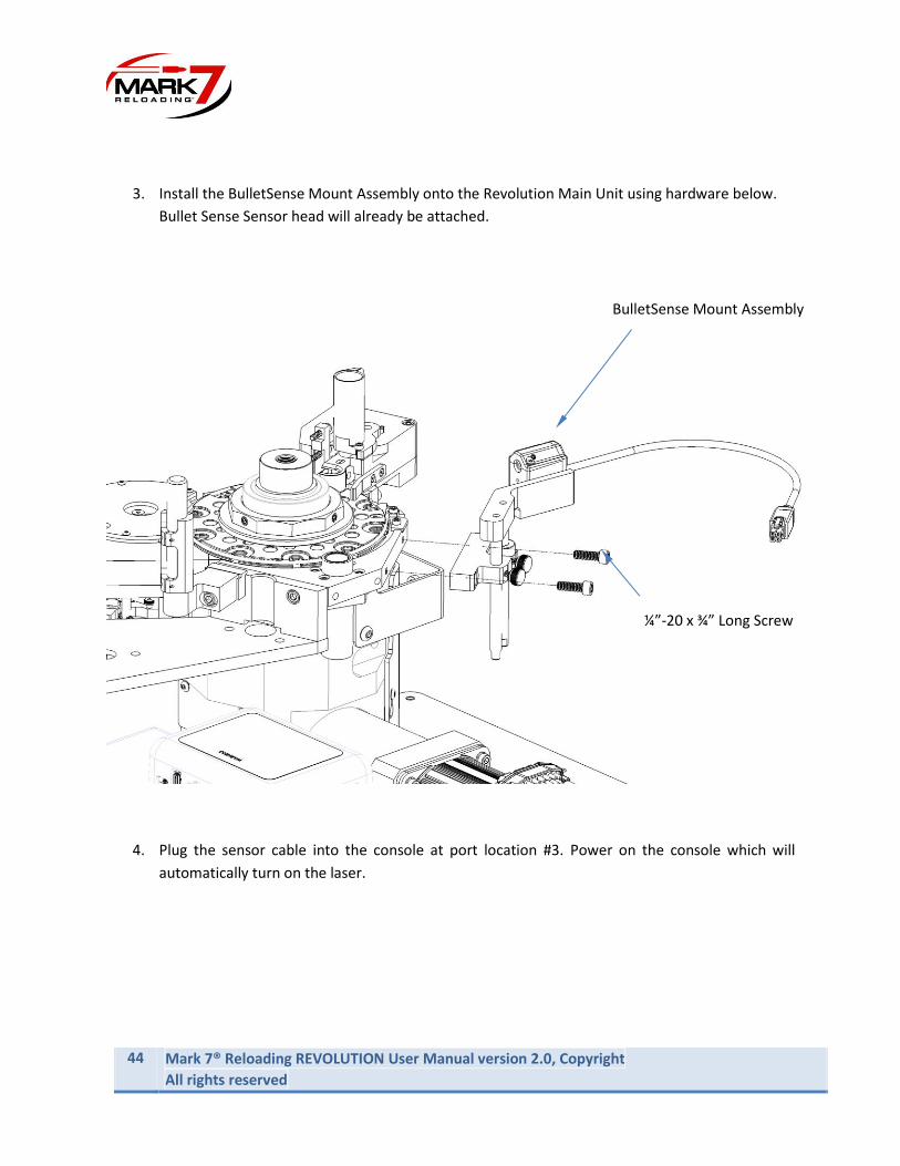
3. Install the BulletSense Mount Assembly onto the Revolution Main Unit using hardware below.
Bullet Sense Sensor head will already be attached.
4. Plug the sensor cable into the console at port location #3. Power on the console which will
automatically turn on the laser.
BulletSense Mount Assembly
¼”-20 x ¾” Long Screw

MARK 7® RELOADING REVOLUTION USER MANUAL VERSION 2.0, COPYRIGHT ALL RIGHTS RESERVED
45
5. Next step is to align the laser, so the mirror reflects the laser beam into the sensor. To adjust use
Adjustment Screws (see Figure 29). When you first power on the sensor look at the mirror to see
where the laser beam is directed. Use a white card to help find the exact position if it’s difficult
to detect the position.
Figure 6: Laser to mirror alignment.
WARNING – Class 3R laser: avoid eye contact at all times; do not look directly into the laser
when adjusting the laser alignment.
6. Adjust Laser beam onto the mirror with the 2X 6-32 Set Screws on the top of the assembly. Once
the Laser diode is hitting the mirror surface. Rotate the mirror so the laser beam is reflected back
to the sensor main body. Once the reflected laser beam appears on the sensor main body,
continue adjusting the set screws a little at a time to direct the laser beam into the sensor hole as
shown in the following figures. If you cannot get the beam to hit the mirror and reflect back into
the eye install the black plastic shim (item 5 see Figure 28) between the mirror and press and
realign (rifle calibers most likely will need the shim).
Laser beam
spot
Laser beam
46 Mark 7® Reloading REVOLUTION User Manual version 2.0, Copyright
All rights reserved
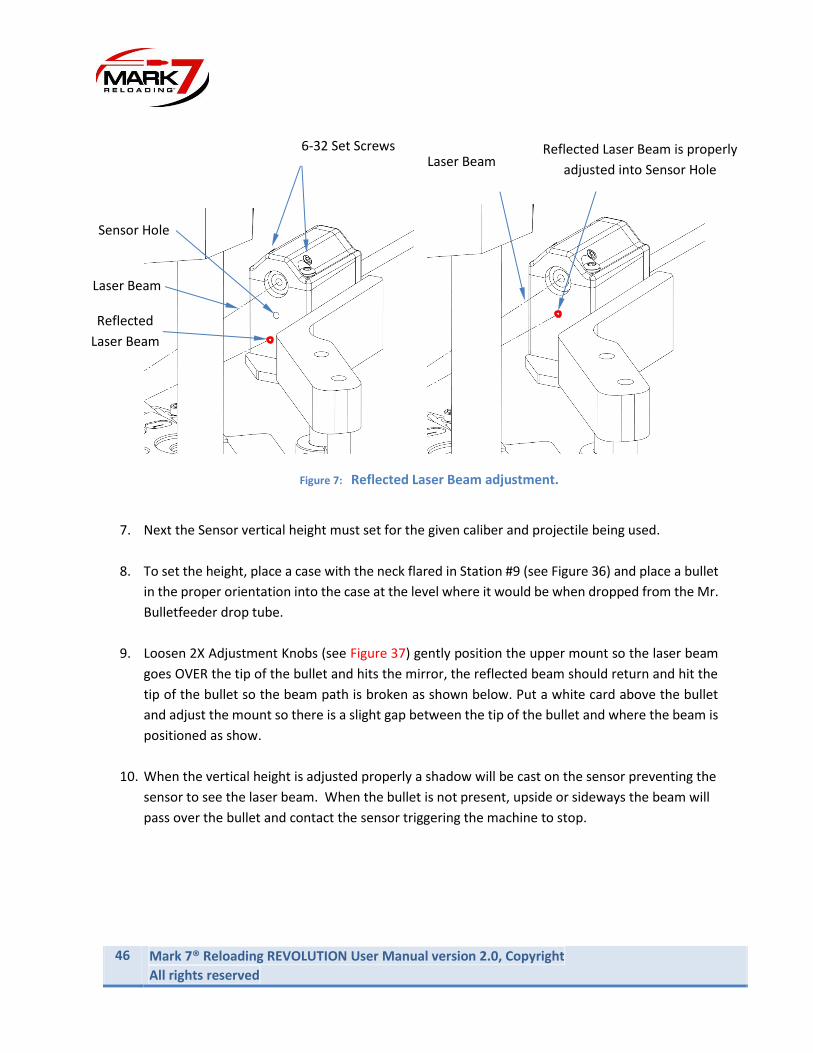
Figure 7: Reflected Laser Beam adjustment.
7. Next the Sensor vertical height must set for the given caliber and projectile being used.
8. To set the height, place a case with the neck flared in Station #9 (see Figure 36) and place a bullet
in the proper orientation into the case at the level where it would be when dropped from the Mr.
Bulletfeeder drop tube.
9. Loosen 2X Adjustment Knobs (see Figure 37) gently position the upper mount so the laser beam
goes OVER the tip of the bullet and hits the mirror, the reflected beam should return and hit the
tip of the bullet so the beam path is broken as shown below. Put a white card above the bullet
and adjust the mount so there is a slight gap between the tip of the bullet and where the beam is
positioned as show.
10. When the vertical height is adjusted properly a shadow will be cast on the sensor preventing the
sensor to see the laser beam. When the bullet is not present, upside or sideways the beam will
pass over the bullet and contact the sensor triggering the machine to stop.
Laser Beam
6-32 Set Screws
Reflected
Laser Beam
Sensor Hole
Reflected Laser Beam is properly
adjusted into Sensor Hole
Laser Beam
MARK 7® RELOADING REVOLUTION USER MANUAL VERSION 2.0, COPYRIGHT ALL RIGHTS RESERVED
47
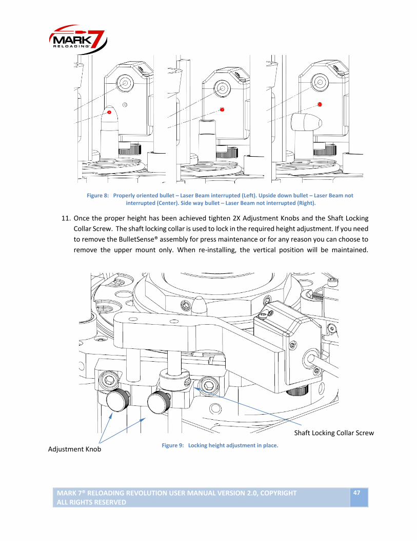
Figure 8: Properly oriented bullet – Laser Beam interrupted (Left). Upside down bullet – Laser Beam not interrupted (Center). Side way bullet – Laser Beam not interrupted (Right).
11. Once the proper height has been achieved tighten 2X Adjustment Knobs and the Shaft Locking
Collar Screw. The shaft locking collar is used to lock in the required height adjustment. If you need
to remove the BulletSense® assembly for press maintenance or for any reason you can choose to
remove the upper mount only. When re-installing, the vertical position will be maintained.
Figure 9: Locking height adjustment in place.
Adjustment Knob
Shaft Locking Collar Screw

48 Mark 7® Reloading REVOLUTION User Manual version 2.0, Copyright
All rights reserved
Operating BulletSense™:
1. With a clear shell plate enter the Reloader application, confirm that you have the required
software firmware version or newer as outlined in the first page of this document.
Figure 10: Sensor page. BulletSense™ enabled.
2. BulletSense™ plugged into Revolution Main Unit Console Port 3.
3. Confirm that the laser is aligned with the sensor opening.
4. Perform a system calibration.
5. Go to the “Sensors” tab and make sure BulletSense® is enabled.
6. Press RUN or Single Cycle. With a clear shell plate, the following notification should appear
stating that a “Bullet Not Properly Positioned.”
Figure 11: BulletSense™ Notification

MARK 7® RELOADING REVOLUTION USER MANUAL VERSION 2.0, COPYRIGHT ALL RIGHTS RESERVED
49
DIGITAL POWDERCHECK™ installation instructions:
Digital Powder Check™ setup:
1. Choose your Powder Check Rod Assy (Item 1 or 2 see Figure 40) based on the following criteria:
• 01 Rod: has a finer optical obstruction – Use with New brass or sorted headstamps
• 02 Rod: Has a coarser optical obstruction – use with Mixed head stamps
Item No. Description QTY
1 Powder Check Rod Assembly - Micro 1
2 Powder Check Rod Assembly - Macro 1
3 Powder Check Housing Assy 1
4 Powder Check Die 1
5 7/8"-14 Thread, Thin Hex Nut 1
6 Powder Probe Tip - Small Pistol 1
7 Powder Probe Tip - Large Pistol 1
8 Powder Probe Tip - Small Rifle 1
9 Powder Probe Tip - Large Rifle 1
1 2 3 4
5
6 7 8 9

50 Mark 7® Reloading REVOLUTION User Manual version 2.0, Copyright
All rights reserved
Figure 11: 01 Rod (left) , 02 Rod Right
2. Choose your Powder Probe Tip for your caliber size. Thread down the probe onto the Rod. Then apply a little purple Loctite to ensure it does not get loose (see Figure 41 for the rod sizes for your caliber).
Figure 12: Powder Probe Tips.
3. Plug the sensor into port #4.
LP SR LR SP

MARK 7® RELOADING REVOLUTION USER MANUAL VERSION 2.0, COPYRIGHT ALL RIGHTS RESERVED
51
Figure 13: PowderSense® console port location.
4. Clear the Shell Plate, perform a fresh calibration.
5. On the tablet tap the SENSORS tab and “enable” the Powder® sensor (will turn green).
Figure 14: Enabling PowderCheck®.

52 Mark 7® Reloading REVOLUTION User Manual version 2.0, Copyright
All rights reserved
6. Thread down just the Die (with Hex Nut) into the Tool Head about halfway.
7. Place Powder Check Housing Assy onto the Die and thread in the set screw to ensure it does not
move while adjusting the height. 8. Place a Case into the Shell Plate with the desired charge and bring the Tool Head all the way down. 9. Adjust the Die height until the Rod assembly is flush with the top of housing assembly. When the
correct proper charge is measured the rod assembly should come close to flush with the top of the housing when the tool head is in the bottom position. If there is too little or to much powder the rod assembly will be below or above housing and will trigger the sensor.
10. Test the sensor with a case containing no powder and a containing a double-charge via single cycle
to ensure you get an "incorrect powder level" error pop-up on the tablet.
Figure 15: PowderCheck® Rod Assy alignment. Properly aligned (Left). Misaligned (Right).
PowderCheck Rod Assy
(flush)
PowderCheck
Housing Assy
PowderCheck Rod Assy
(too low)
Set
Screw
Die
Hex Nut

MARK 7® RELOADING REVOLUTION USER MANUAL VERSION 2.0, COPYRIGHT ALL RIGHTS RESERVED
53
Primer Orientation Sensor Installation Instructions Packaging Content:
Item No. Description QTY
1 Primer Orientation Sensor Main Body 1
2 8-32x 1/2" Socket Head Screw 2
3 Probe 1
4 Probe Spring (*1 Spare) 2
5 Indicator Spring (*1 Spare) 2
1
2 3
4
5

54 Mark 7® Reloading REVOLUTION User Manual version 2.0, Copyright
All rights reserved
Installation Instructions: Before first use lubricate with 1 drop of light machine oil all interfaces below:
1. Pin and Bushing 2. Pin and Rocker 3. Rocker and Retainer 4. Probe and Housing 5. Retainer and Housing
Figure 16: Primer Orientation Sensor lube points.
The Primer orientation sensor installs into station # 5. In order to install the sensor the Shell Plate must
be removed or lifted up to remove the spacer housing. Although it’s not required, we recommend to
remove the Tool Head for full access. Below are the installation steps for installing the sensor on a
Revolution (shown) or Evolution (same procedure).
Step 1: Removing Tool Head and Shell Plate.
• Remove Tool Head.
• Remove Shell Plate Nut.
• Loosen the Shell Plate retainer clamps and remove the Shell Plate spring.
• Remove the Shell Plate.
• Remove Spacer Block by loosening 2X 10-32 from the underside of the Priming Assembly with a
9/64” Allen Key.
1
2
3
4
1
5
1

MARK 7® RELOADING REVOLUTION USER MANUAL VERSION 2.0, COPYRIGHT ALL RIGHTS RESERVED
55
Figure 17: Revolution Press Top End disassembled for Sensor Installation
Step 2: Installing Probe Retractor and Springs
Place the two springs into the spring wells in the primer housing as shown. Apply a small amount of red
and tacky grease on the springs. Use light machine oil to work the probe into the brass bushing. Once the
springs are installed, insert the probe retractor into the large spring.
Spacer Block
Revolution Press
Spacer Block
Hardware – re-use
56 Mark 7® Reloading REVOLUTION User Manual version 2.0, Copyright
All rights reserved
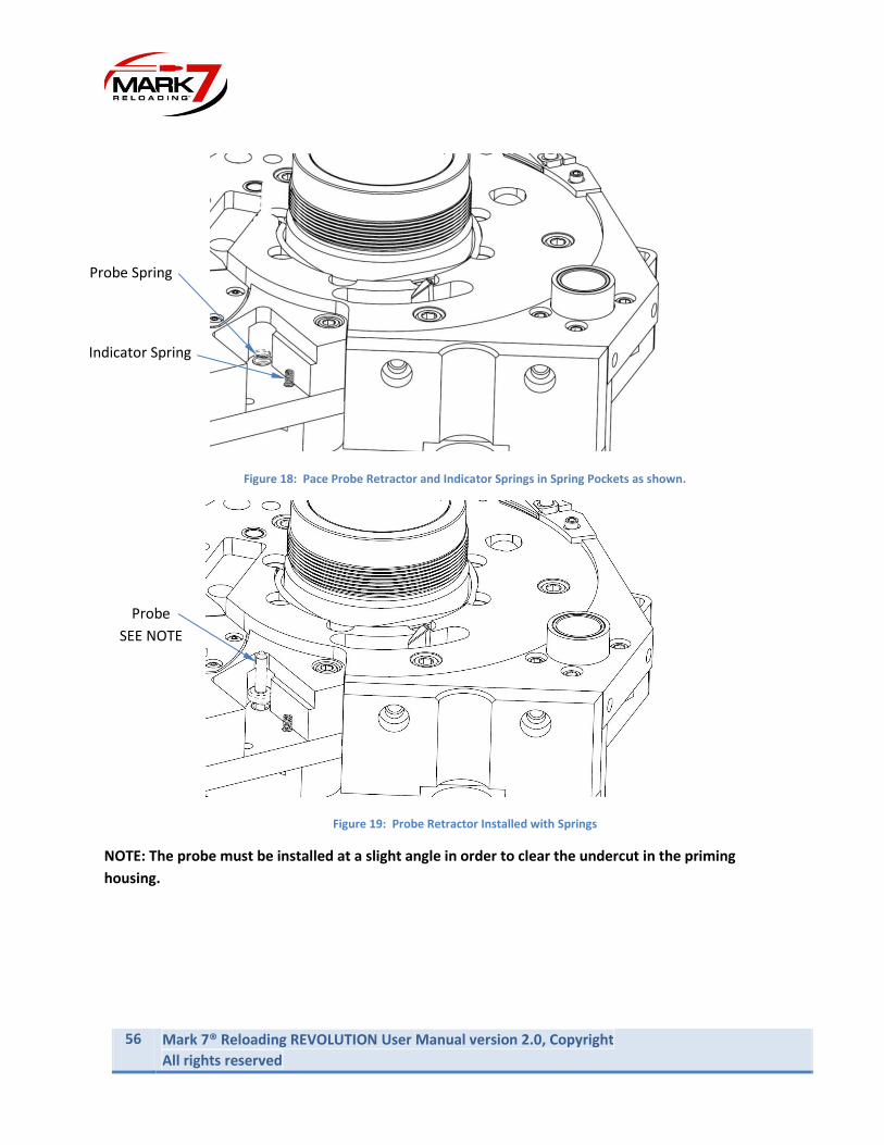
Figure 18: Pace Probe Retractor and Indicator Springs in Spring Pockets as shown.
Figure 19: Probe Retractor Installed with Springs
NOTE: The probe must be installed at a slight angle in order to clear the undercut in the priming
housing.
Probe Spring
Indicator Spring
Probe
SEE NOTE

MARK 7® RELOADING REVOLUTION USER MANUAL VERSION 2.0, COPYRIGHT ALL RIGHTS RESERVED
57
Step 3: Installing the Primer Orientation Sensor Main Body
Carefully lower the sensor body straight down so the probe retractor enters the bronze sleeve
bearing and the indicator finger pin enters the spring. The sensor should mount fully flush into the pocket
with no resistance. If it does not seat properly remove and reseat. Re-use the QTY 2 8-32 screws from the
underside of the priming system to secure the sensor the priming assembly. Spare screws are included if
needed.
Figure 20: Primer Orientation Sensor Installed
Once the Sensor is fully installed add a couple drops of light weight oil on the probe retractor and
moving components and manually actuate the sensor to make sure it is moving smoothly.
Step 4: Re-install the Press components:
• Install Shell Plate.
• Install Shell Plate Spring and set tension.
• Install Shell Plate Nut.
• Install Tool Head*.
Note: When installing the Tool Head always perform the final tightening of the Tool Head with the crank
assembly in the down position.

58 Mark 7® Reloading REVOLUTION User Manual version 2.0, Copyright
All rights reserved
Step 5: Adjusting Optical Sensor to Desired Primer Depth
With the machine powered off and the tool head in the UP POSITION place a case with a seated primer
to the desired depth into station #5. Make sure the Shell Plate nut is fully threaded down to the desired
tightness. When you Install the Primed case, you will notice the indicator Pin will move up slightly. With
the case installed the top of the indicator pin should be FLUSH with the top of the Sensor Housing. If the
sensor Housing is higher or lower loosen the two socket head Screws on the back of the sensor housing
and reset the height.
Figure 21: Setting Optical Sensor Position
Step 6: Plug the Sensor into Port #2 on the rear of the electronics unit
Figure 22: Plug Sensor into Port #2 as Shown
Primed Case
Indicator Pin
Sensor Housing
Shell Plate Nut
MARK 7® RELOADING REVOLUTION USER MANUAL VERSION 2.0, COPYRIGHT ALL RIGHTS RESERVED
59
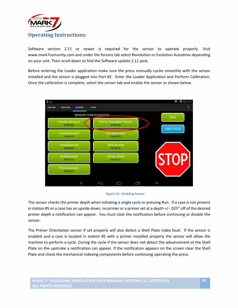
Operating Instructions:
Software version 2.11 or newer is required for the sensor to operate properly. Visit
www.mark7comunity.com and under the forums tab select Revolution or Evolution Autodrive depending
on your unit. Then scroll down to find the Software update 2.11 post.
Before entering the Loader application make sure the press manually cycles smoothly with the sensor
installed and the sensor is plugged into Port #2. Enter the Loader Application and Perform Calibration.
Once the calibration is complete, select the sensor tab and enable the sensor as shown below.
Figure 23: Enabling Sensor
The sensor checks the primer depth when initiating a single cycle or pressing Run. If a case is not present
in station #5 or a case has an upside down, no primer or a primer set at a depth +/- .025” off of the desired
primer depth a notification can appear. You must clear the notification before continuing or disable the
sensor.
The Primer Orientation sensor if set properly will also detect a Shell Plate index fault. If the sensor is
enabled and a case is located in station #5 with a primer installed properly the sensor will allow the
machine to perform a cycle. During the cycle if the sensor does not detect the advancement of the Shell
Plate on the upstroke a notification can appear. If the notification appears on the screen clear the Shell
Plate and check the mechanical indexing components before continuing operating the press.
60 Mark 7® Reloading REVOLUTION User Manual version 2.0, Copyright
All rights reserved
Software and Firmware Update Instructions
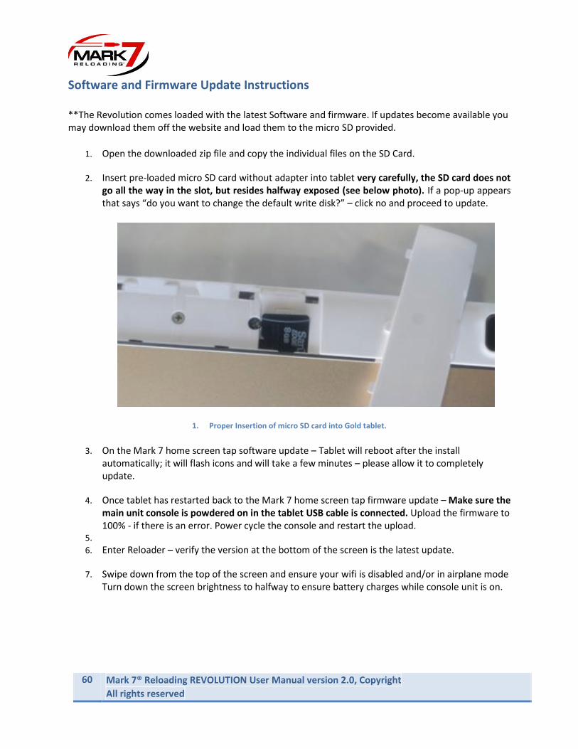
**The Revolution comes loaded with the latest Software and firmware. If updates become available you may download them off the website and load them to the micro SD provided.
1. Open the downloaded zip file and copy the individual files on the SD Card.
2. Insert pre-loaded micro SD card without adapter into tablet very carefully, the SD card does not go all the way in the slot, but resides halfway exposed (see below photo). If a pop-up appears that says “do you want to change the default write disk?” – click no and proceed to update.
1. Proper Insertion of micro SD card into Gold tablet.
3. On the Mark 7 home screen tap software update – Tablet will reboot after the install automatically; it will flash icons and will take a few minutes – please allow it to completely update.
4. Once tablet has restarted back to the Mark 7 home screen tap firmware update – Make sure the main unit console is powdered on in the tablet USB cable is connected. Upload the firmware to 100% - if there is an error. Power cycle the console and restart the upload.
5. 6. Enter Reloader – verify the version at the bottom of the screen is the latest update.
7. Swipe down from the top of the screen and ensure your wifi is disabled and/or in airplane mode Turn down the screen brightness to halfway to ensure battery charges while console unit is on.

MARK 7® RELOADING REVOLUTION USER MANUAL VERSION 2.0, COPYRIGHT ALL RIGHTS RESERVED
61
Mark 7® Revolution Recommended Maintenance.
There are a few areas on the Revolution that should be lubricated daily, we recommend checking all the
locations noted below before each reloading session to ensure they are properly lubricated.
2. Revolution grease points.
Swage
Grease point
Main Bearing
grease point
Ram
Light weight oil
Case Feed
Cam grease
point
Primer Rocker
grease point
Light grease under
shell plate lock nut
Access the crank
grease point in the
down position crank
shield cut out use red
and tacky #2 grease
until it oozes a bit
62 Mark 7® Reloading REVOLUTION User Manual version 2.0, Copyright
All rights reserved
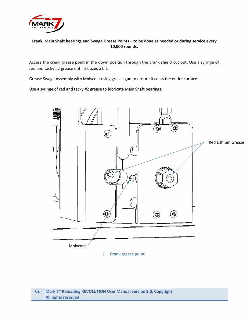
Crank, Main Shaft bearings and Swage Grease Points – to be done as needed or during service every
10,000 rounds.
Access the crank grease point in the down position through the crank shield cut out. Use a syringe of
red and tacky #2 grease until it oozes a bit.
Grease Swage Assembly with Molycoat using grease gun to ensure it coats the entire surface.
Use a syringe of red and tacky #2 grease to lubricate Main Shaft bearings.
3. Crank grease point.
Molycoat
Red Lithium Grease
MARK 7® RELOADING REVOLUTION USER MANUAL VERSION 2.0, COPYRIGHT ALL RIGHTS RESERVED
63
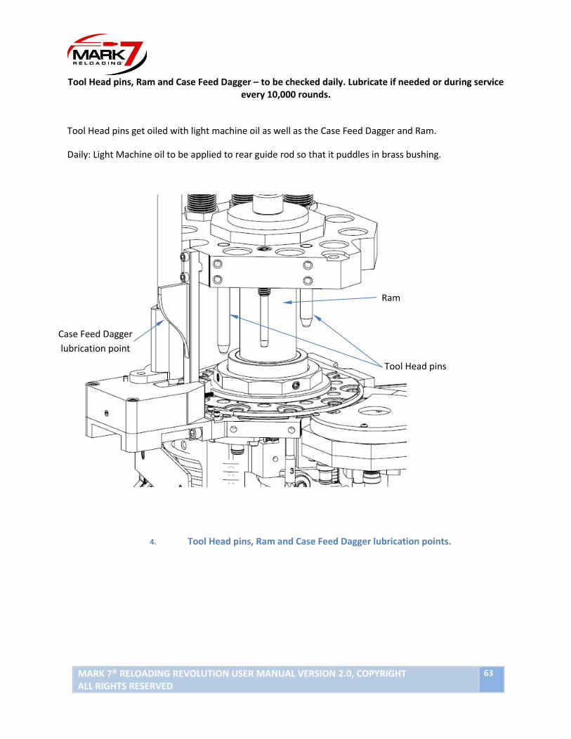
Tool Head pins, Ram and Case Feed Dagger – to be checked daily. Lubricate if needed or during service every 10,000 rounds.
Tool Head pins get oiled with light machine oil as well as the Case Feed Dagger and Ram.
Daily: Light Machine oil to be applied to rear guide rod so that it puddles in brass bushing.
4. Tool Head pins, Ram and Case Feed Dagger lubrication points.
Ram
Case Feed Dagger
lubrication point
Tool Head pins

64 Mark 7® Reloading REVOLUTION User Manual version 2.0, Copyright
All rights reserved
Swage and primer punch grease point – to be checked daily. Lubricate if needed or during service
every 10,000 rounds.
Daily: Drop of light machine oil behind the rocker on the bolt threads itself.
• If bolt or/and rocker were removed during maintenance – apply red and tacky #2 grease to the
bolt/rocker surface.
• Use red and tacky #2 grease to lubricate primer punch. Lubricate if needed or during service
every 10,000 rounds.
5. Swage grease points.
Red and Tacky
#2 grease
Red and Tacky
#2 grease
Light machine oil

MARK 7® RELOADING REVOLUTION USER MANUAL VERSION 2.0, COPYRIGHT ALL RIGHTS RESERVED
65
Under the Shell Plate Service Every 10,000 rounds:
If you do remove the shell plate for maintenance - the Wave Spring around the Sleeve
underneath the shell plate (just around the bottom edge where the shell plate is against it) needs a
coat of Red and Tacky#2. Also, a coat of Red and Tacky#2 on the underside of the shell plate nut and
up the top plate sleeve.
6. Under the Shell Plate grease point.
Wavy Spring
under the Shell
Plate
Red and Tacky
#2 grease Sleeve

66 Mark 7® Reloading REVOLUTION User Manual version 2.0, Copyright
All rights reserved
Internal Guide Rod:
Daily: Few drops of Starrett Light machine oil for the internal guide rod brass bushing every 100
or so cycles to break it in then as needed after cleaning.
7. Internal Guide Rod lubrication point.
Loosen
screws
Light machine oil
Swing the Shield CCW

MARK 7® RELOADING REVOLUTION USER MANUAL VERSION 2.0, COPYRIGHT ALL RIGHTS RESERVED
67
Shell Plate and Primer Disk:
Daily: Check the shell plate for tightness, you want it to move in neutral with your fingertips. Check the
shell plate lock nut 4x nylon tipped screws (careful not to tighten too much!) as well as the tightness of
the shell plate spring – neither should impact indexing so be careful not to overtighten. Get them snug,
then back of an 1/8 of a turn.
Daily: Check the tool head bolt with your ½” allen wrench for tightness (approximate 15 to 20 ft-lbs)
Tip* Always re-tighten tool head bolt and all guide rod bracket screws with toolhead in down position.
Daily: Check the Primer disk bolts for tightness. Always re-tighten bolts with tool head in the down
position.
Storage Recommendations
The following is the proper procedure for storage after a session of use:
1. Ensure that the shell plate is clear of any brass
2. Check the need for lubrication after every session and apply it as necessary at the key
lubrication points outlined in the user manual. Insufficient lubrication creates a potentially
dangerous situation and may lead to unreliable results
3. Turn off the power to the console
4. Turn off the power to the case feeder and the bullet feeder
5. Turn off the power to the table
Reloading Manual Ensuring proper system operation
Before using any Mark 7® Revolution higher speeds you must ensure that press works perfectly in single
cycle mode or the lowest speed setting. This includes proper settings for the type of ammunitions you are
reloading at each of the die stations.
There is a delicate interaction between the bullet dropper and the amount of brass flair provided by
expander die for pistol. A strategy that may be helpful is to remove the bullet feeder spring tube leaving
just the bottom portion of the bullet dropper. Run the machine on slow adjusting both the bullet feeder
drop die and expander die until you get the operation you are looking for. You can manually insert bullets
into the dropper and single cycle the machine. Make sure that bullets are not toppling over. If so, you
may need to increase flair and/or increase depth of the dropper mechanism. Once you have run several
cycles without issue you can tighten everything up and continue operation.
68 Mark 7® Reloading REVOLUTION User Manual version 2.0, Copyright
All rights reserved
WARNING - Bullets behave differently at higher speed settings, small variations in bullet dimensions have
unpredictable results in bullet feeding. Take good care that if you are getting results you are not expecting
like excessive bullet topple, bullets stuck in the dropper, etc.
Calibration
Calibration can only be done when the Mark 7® Revolution is empty with no casings in the shell plate.
Only after calibration is complete you may start reloading ammunition.
Test Rounds
Once calibration is completed, and you have loaded the shell plate with brass you must take the first
round produced and remove it. Take the next two rounds and check the measurements with high
quality calipers. Adjust dies if necessary and repeat to ensure that setting meet the specifications that
you are loading.
Digital Clutch Setting
The Digital Clutch adjusts the torque of the motor from the minimum torque required to drive the press
to the maximum torque of the motor. This range is from 0-20 on the tablet main control screen. It is
important to note that increasing the Digital Clutch only increases the motor torque when the tool head
is in the down stroke approaching the shell plate for sizing/decapping/bullet seating/crimping operations.
When the tool head retracts the torque is hard programmed at the minimum level to maximize jam
sensitivity and to best protect the indexing components of the press.
8. Digital Clutch Adjustment on control screen.
1. The Mark7® RevolutionTM is shipped with the Digital Clutch at 0. This is the minimum torque
required to run the press dry (without components).
2. When you are ready to process brass or reload once fired brass use the following table as a
guide for starting torque levels. Always use lubed brass to run the Digital Clutch as low as
possible. Depending on the condition of the brass you may be able to run the machine on lower

MARK 7® RELOADING REVOLUTION USER MANUAL VERSION 2.0, COPYRIGHT ALL RIGHTS RESERVED
69
settings than listed below. We recommend running the machine on the lowest Digital Clutch
setting possible for the given caliber.
9. Recommend Digital Clutch settings for general calibers
Small Pistol Large Pistol Small Rifle Large Rifle
Digital Clutch 2-5 3-10 5-12 12-20
3. If the Digital Clutch is set to low for a given operation the following notification will appear on
the tablet usually close to the bottom of the stoke when the sizing/decap die is engaged.
10. Digital clutch notification.
4. Sometimes pressing RUN again will provide enough torque to push through the sizing operation.
If the notification box appears again the clutch will need to be increased and or check for a hard
jam causing the torque out condition.
5. Tap STOP to put the motor and neutral and to reset the motor.
6. Next JOG tool head up and inspect the shell plate area for a jam. If everything looks okay, increase
the Digital Clutch by 1 to 2 digits, then press RUN or END CYCLE. Repeat the process until the
machine pushes through and completes the stroke.
7. Continue to run at the new Digital Clutch setting until you get consistent stroke cycle
completion.
Special Notes:
• The Digital Clutch is speed dependent; you may need to slightly increase the Digital Clutch as
you increase the speed of the drive.
• Use caution when operating the machine with a Digital Clutch over 15 or HIGH.
• Always use Lubed brass for best results and to allow running on the lowest clutch setting
possible.
• Check for proper belt tension and for play in the crank assembly regularly.

70 Mark 7® Reloading REVOLUTION User Manual version 2.0, Copyright
All rights reserved
• When clearing jams always check and or clear the case in station #5 or 6 (powder) to avoid a
double or no charge before continuing.
- Clearing Jams
When a jam occurs, the motor will stop and a notification on the tablet will appear saying Digital Clutch
Activated. It’s important to note that this message may not always mean there is a jam in the press,
sometimes motor may have just torqued out due to the Digital Clutch being set too low for a given
operation.
We recommend taking the following steps when a jam occurs.
1. Inspect the tool head and shell plate area of the press to determine the cause of stoppage.
2. Press STOP e to put the motor in neutral (the LED on the back of the orange will change from
green to orange in this state)
3. If you are able to determine the cause of the jam or stoppage, Use the JOG commands to back
off the Tool head in order to rectify the issue. Once cleared hit RUN to continue as normal.
4. If you are not able to determine the cause of the jam, manually actuate the press by using an
11/16” wrench or socket on the front of the machine. Once the jam is clear perform a full
stroke manually before continuing.
In some cases, a hard jam may occur. If the jog buttons do not move the Tool Head, then the Mark 7®
Revolution needs to be powered down. Once powered down, attempt to manually clear the jam. In doing
so, you must clear the shell plate and confirm that the press can manually index. Run the full cycle of the
machine a couple of times by manipulating the belt manually and ensure the machine is in good working
order. Then you can repower the machine and continue.
WARNING -Never attempt to clear a jam by placing your fingers in the mechanism of the Mark 7®
Revolution. Always ensure that the Mark 7® Revolution is off and power is cut off to the Mark 7®
Revolution before attempting to clear a jam.
If you experience a jam or any type of activity that requires you to turn off the Mark 7® Revolution at the
console, you will be required to calibrate the Mark 7® Revolution again. Always repeat the process of
ensuring that the measurements on your brass or ammunition are that same that they were in your
previous calibration – they will likely be within acceptable tolerances.

MARK 7® RELOADING REVOLUTION USER MANUAL VERSION 2.0, COPYRIGHT ALL RIGHTS RESERVED
71
Settings
There are a few settings that your Mark 7® Revolution has built in. They include Production rate, digital
clutch, dwell and index speed. You can experiment with different settings to ensure that you are making
the highest quality ammunition.
Communications Errors
Please follow these steps to minimize electrical interference from external reloading devices that
contain motors:
• Check USB connection between tablet and Console is secure.
• Install the Mr. Bulletfeeder filter included with the system.
• Route Mr. Bulletfeeder power cables away from tablet USB and power cords. Do not zip tie the Case collator power cord to case collator pole.
• Power the Mr. Bulletfeeder & Case collator on their own surge protector if possible.
• Make sure the USB connectors are secure and away from the moving press components.
• Check your electrical grounds, grounding the machine to an independent true earth ground is recommended.
In the event of this error you must clear the shell plate from all brass, rectify the situation above that
caused the error, turn on the machine, proceed with calibration, and restart your operation.
If this error occurs during machine operation and you have followed the above steps please contact us
for technical support.
Troubleshooting
Refer to the knowledge base section on our website under SUPPORT for troubleshooting articles relating
to setup and operation.
http://www.markvii-loading.com/
Please contact us for technical support
Phone: 1-888-462-7577
Hours: 9:00am-4:30pm, ET, M–F