Embed Size (px)
Citation preview
Proceedings of the 19th
Offshore Symposium, February 2014, Houston, Texas
Texas Section of the Society of Naval Architects and Marine Engineers
1
MARINE SIMULATOR FOR JACK-ST.MALO FACILITY
CHRIS HUDSON
MARINE OPERATIONS, CHEVRON
ANKUR RASTOGI
TECHNICAL ADVISOR, KONGSBERG OIL AND GAS TECHNOLOGIES, INC.
TIRTHARAJ BHAUMIK
SENIOR NAVAL ARCHITECT, KBR-GVA
ABSTRACT
A Marine Simulator was developed for the Jack-St. Malo field located in approximately
7000 feet of water in the Gulf of Mexico Walker Ridge block. The simulator presented
operational information in a form similar to that on the actual facility and provided
operational personnel with extensive operational experience and training on scenarios as may
be faced in the actual facility, prior to and subsequent to facility start-up.
The design of the ballast system for this Semi-Submersible Floating Production Unit
(FPU) called for a comprehensive training procedure as an added operational safety measure
for the marine operators. The Jack-St. Malo Marine Simulator utilizes process and safety
control configurations that are the same as the facility. It includes a Load Management system
and an Environment and Facilities Monitoring System (EFMS) integrated with a high fidelity
dynamic model for the hull ballast and bilge systems. The simulator is an outstanding training
tool that can be used during the life of the FPU to train operators for various operating
scenarios and develop guidelines to handle emergency scenarios.
The simulator proved to be an effective tool to perform Control System check out during
pre-commissioning. Lifts for production, generation, compression modules were first tested on
the Marine Simulator before actual lifts were conducted in the yard. Naval architects were
consulted to verify anticipated ballasting operations before actual operations. The simulator
gave operators a feel of the Process Dynamics, Process Control, and Safety System and
familiarity with the DCS Graphics well before start up. The simulator was successfully used as
a dummy platform along with the Load Management Advisory Program to demonstrate the
ballast procedure for the successive installation of three heavy modules onboard the actual
platform. Scenarios simulated include hurricane shutdown and start-up, instrument failures,
damaged mooring line situations and damaged compartment scenarios due to collision or
inadvertent flooding, among many others.
Operator training to operate Jack-St. Malo Ballast and Bilge systems using facility
Operator graphics and control system was thoroughly carried out using this Simulator and this
contributed to the high level of confidence in Marine operations including lifts and ballasting
operations. The simulator was a useful tool for validating Standard Operating Procedures
before actual facility start-up.
Keywords: Jack St .Malo, Simulator, Marine
Proceedings of the 19th
Offshore Symposium, February 2014, Houston, Texas
Texas Section of the Society of Naval Architects and Marine Engineers
2
INTRODUCTION
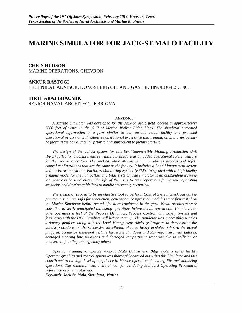
Jack and St. Malo fields are located in the Gulf of Mexico Walker Ridge blocks situated in approximately 7000
feet of water. The Jack-St. Malo field development consists of 12 sub-sea wells connected to three sub-sea
manifolds tied back to the Floating Production Unit with a production capacity in the range of 120,000 to 150,000
BPD of oil and 37.5 MMSCFD of natural gas. At approximately 54,000 tons hull weight supporting 25,000 tons
topsides, Jack-St. Malo’s Hull is among the world’s largest oil production platforms to date to be operated at a draft
of approximately 136 feet. The hull consists of a ring pontoon, four columns and a deck box below the lower deck
level. The topsides modules are located on top of the hull at the main deck level of 230 feet above keel and in
addition there is a process and subsea equipment located in the deck box. See Figure 1 for the Jack- St. Malo Field
layout.
The high-complexity of the Jack-St. Malo (JSM) field development required a more effective training system
for the operators. The design of the ballast system for this Semi-Submersible Floating Production Unit (FPU) is
based on the principles of the GVA Sea-Loc System. This made it simple and easy-to-use, but called for a
comprehensive training procedure as an added operational safety measure for the marine operators. Jack-St. Malo’s
hull design has the following unique features as part of the Sea-Loc design -
• Ballast tanks are filled with water from deck level by submerged caisson type ballast/utility sea water lift
pumps located outside the facility, hence there are no hull penetrations below the operational draft (closed hull
philosophy).
• De-ballasting (emptying of tanks) is performed by conventional centrifugal pumps located in pontoon
compartments. As an option all these pumps can be designed to operate submerged.
• Combined Ballast/Main bilge function, reducing the overall number of pumps simplifies operation
• All ballast tanks (except column ballast tanks above elevation 157 feet) are filled by gravity; hence there is
no possibility to over-pressurize tanks.
The Marine Simulator presents operational information in a form similar to that on the actual facility and
provides operational personnel with extensive operational experience and training on scenarios as may be faced in
the actual facility, prior to and subsequent to plant start-up. A Lifecycle Simulator concept was applied such that the
simulator grew and developed as the project progressed and was used in many phases of the project: from
engineering studies, through control system check-out, operator training, commissioning support to possible future
tie-backs engineering design and support functions. Similar simulators have been developed in the past for topsides
(Dziubla et al, 2004), but the Marine Simulator for JSM was developed mainly for the Hull system.
Figure 1: Jack-St. Malo Field Layout
Proceedings of the 19th
Offshore Symposium, February 2014, Houston, Texas
Texas Section of the Society of Naval Architects and Marine Engineers
3
SIMULATOR SCOPE
The Jack St. Malo Marine Simulator was developed to provide an integrated simulator for the Jack St. Malo
Marine facilities. This simulator provides marine operations personnel with a training environment, prior to and
subsequent to facilities start-up. Transient response of the information provided accurately replicates that which
would be observed on the actual platform when subject to the same or similar disturbances. To obtain a high-fidelity
response to the disturbances, simulator scope includes most of the subsea, topsides and hull equipment, piping and
instrumentation.
The process model for topsides, subsea and hull is connected to an emulation of facility control system, which
has the exact same configuration for process logic and safety controllers and operator station screens as will be
running on the facility. Location and elevation information for all the topsides and hull equipment and
instrumentation is included in the simulator to accurately calculate platform inclination and draft under all scenarios.
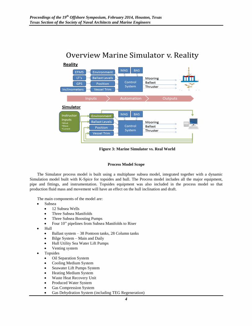
The Jack-St. Malo Marine Simulator is built using Stimulated Control configuration which is the same as the
Facility control configuration. Load Management system and an EFMS system are integrated with a high fidelity
process model for the hull, topsides and subsea. The Simulator uses actual DCS graphics for Operator stations.
Model Scope and control system scope is detailed in next section. Environment variables are set up by the Instructor
in the Simulator to simulate environment as seen in Figure 3 below. Mooring Advisory System (MAS) and Ballast
Advisory System (BAS) similar to those used in actual facility are provided to the student (Marine Operator) to aid
in facility operation.
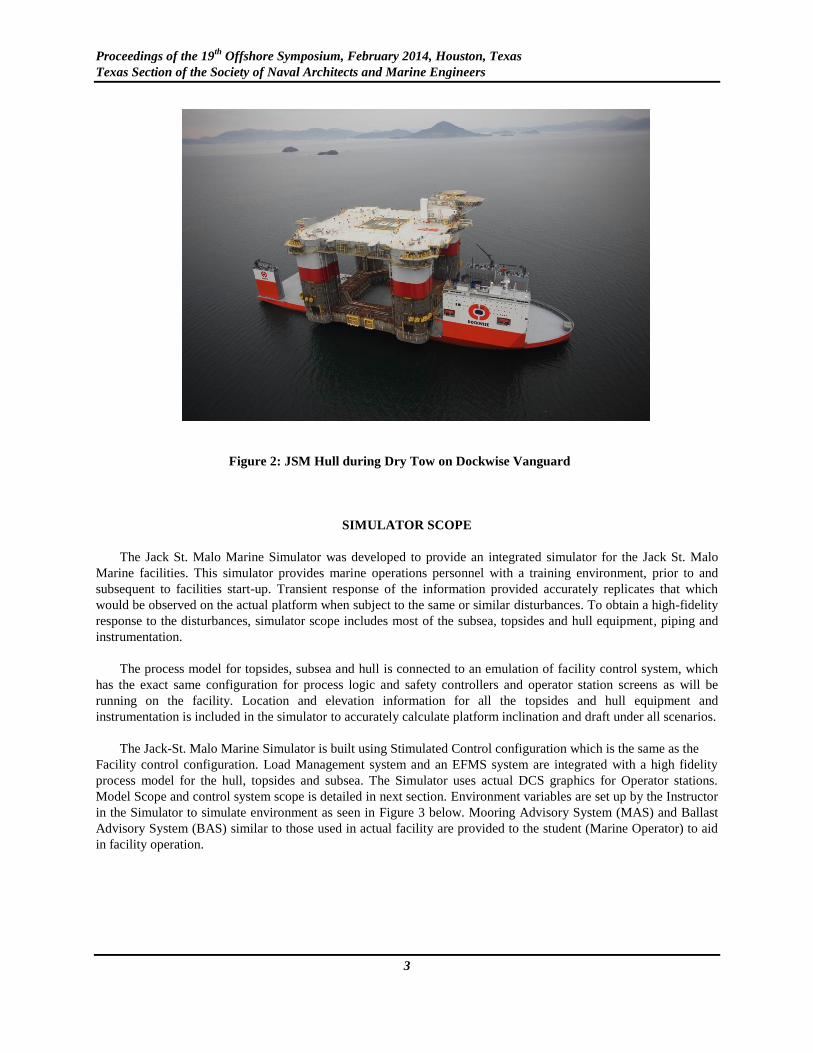
Figure 2: JSM Hull during Dry Tow on Dockwise Vanguard
Proceedings of the 19th
Offshore Symposium, February 2014, Houston, Texas
Texas Section of the Society of Naval Architects and Marine Engineers
4
Process Model Scope
The Simulator process model is built using a multiphase subsea model, integrated together with a dynamic
Simulation model built with K-Spice for topsides and hull. The Process model includes all the major equipment,
pipe and fittings, and instrumentation. Topsides equipment was also included in the process model so that
production fluid mass and movement will have an effect on the hull inclination and draft.
The main components of the model are:
Subsea
12 Subsea Wells
Three Subsea Manifolds
Three Subsea Boosting Pumps
Four 10” pipelines from Subsea Manifolds to Riser
Hull
Ballast system – 38 Pontoon tanks, 28 Column tanks
Bilge System – Main and Daily
Hull Utility Sea Water Lift Pumps
Venting system
Topsides
Oil Separation System
Cooling Medium System
Seawater Lift Pumps System
Heating Medium System
Waste Heat Recovery Unit
Produced Water System
Gas Compression System
Gas Dehydration System (including TEG Regeneration)
Figure 3: Marine Simulator vs. Real World
Proceedings of the 19th
Offshore Symposium, February 2014, Houston, Texas
Texas Section of the Society of Naval Architects and Marine Engineers
5
Chemical Injection System – Low-Dosage Hydrate Inhibitor (LDHI) and Methanol
HP and LP Flare System
Fuel Gas System
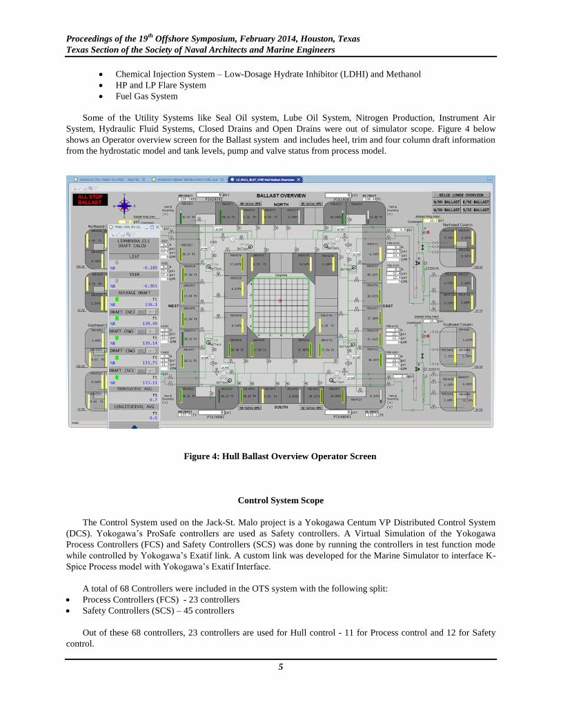
Some of the Utility Systems like Seal Oil system, Lube Oil System, Nitrogen Production, Instrument Air
System, Hydraulic Fluid Systems, Closed Drains and Open Drains were out of simulator scope. Figure 4 below
shows an Operator overview screen for the Ballast system and includes heel, trim and four column draft information
from the hydrostatic model and tank levels, pump and valve status from process model.
Control System Scope
The Control System used on the Jack-St. Malo project is a Yokogawa Centum VP Distributed Control System
(DCS). Yokogawa’s ProSafe controllers are used as Safety controllers. A Virtual Simulation of the Yokogawa
Process Controllers (FCS) and Safety Controllers (SCS) was done by running the controllers in test function mode
while controlled by Yokogawa’s Exatif link. A custom link was developed for the Marine Simulator to interface K-
Spice Process model with Yokogawa’s Exatif Interface.
A total of 68 Controllers were included in the OTS system with the following split:
Process Controllers (FCS) - 23 controllers
Safety Controllers (SCS) – 45 controllers
Out of these 68 controllers, 23 controllers are used for Hull control - 11 for Process control and 12 for Safety
control.
Figure 4: Hull Ballast Overview Operator Screen
Proceedings of the 19th
Offshore Symposium, February 2014, Houston, Texas
Texas Section of the Society of Naval Architects and Marine Engineers
6
SYSTEM ARCHITECTURE
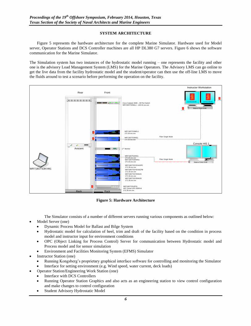
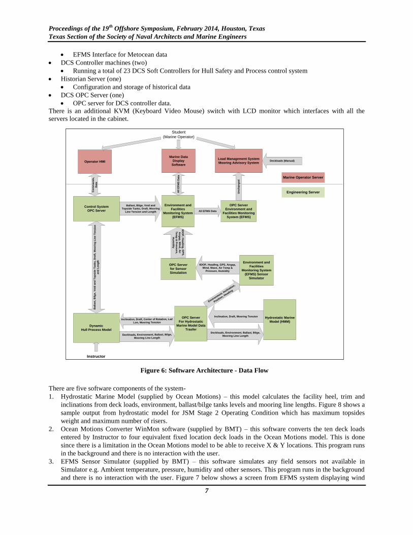
Figure 5 represents the hardware architecture for the complete Marine Simulator. Hardware used for Model
server, Operator Stations and DCS Controller machines are all HP DL380 G7 servers. Figure 6 shows the software
communication for the Marine Simulator.
The Simulation system has two instances of the hydrostatic model running – one represents the facility and other
one is the advisory Load Management System (LMS) for the Marine Operators. The Advisory LMS can go online to
get the live data from the facility hydrostatic model and the student/operator can then use the off-line LMS to move
the fluids around to test a scenario before performing the operation on the facility.
The Simulator consists of a number of different servers running various components as outlined below:
Model Server (one)
Dynamic Process Model for Ballast and Bilge System
Hydrostatic model for calculation of heel, trim and draft of the facility based on the condition in process
model and instructor input for environment conditions
OPC (Object Linking for Process Control) Server for communication between Hydrostatic model and
Process model and for sensor simulation
Environment and Facilities Monitoring System (EFMS) Simulator
Instructor Station (one)
Running Kongsberg’s proprietary graphical interface software for controlling and monitoring the Simulator
Interface for setting environment (e.g. Wind speed, water current, deck loads)
Operator Station/Engineering Work Station (one)
Interface with DCS Controllers
Running Operator Station Graphics and also acts as an engineering station to view control configuration
and make changes to control configuration
Student Advisory Hydrostatic Model
RackRack
WR718OTS3INS1
172.18.xxx.xxx
WR718OTS3MDL1
172.18.xxx.xxx
FrontRear
WR718OTS3YEMU01
172.18.xxx.xxx
WR718OTS3KVM1
Avocent
Cisco Catalyst 4948 – 48 Port Switch
WR718OTS3SEL1 - 146.32.xxx.xxx
17" Monitor
WR718OTS3EWS1
172.18.xxx.xxx
WR718OTS3HIS1
172.18.xxx.xxx
Instructor Workstation
Matrox Extio KVM
Console HIS 1
Matrox Extio KVM
Fiber Single Mode
Fiber Single Mode
WR718OTS3YEMU02
172.18.xxx.xxx
WR718OTS3YEXAOPC
172.18.xxx.xxx
WR718OTS3YEXAQTM
172.18.xxx.xxx
WR718OTS3UPS1
APC Smart UPS 3000VA
172.18.xxx.xxx
Figure 5: Hardware Architecture
Proceedings of the 19th
Offshore Symposium, February 2014, Houston, Texas
Texas Section of the Society of Naval Architects and Marine Engineers
7
EFMS Interface for Metocean data
DCS Controller machines (two)
Running a total of 23 DCS Soft Controllers for Hull Safety and Process control system
Historian Server (one)
Configuration and storage of historical data
DCS OPC Server (one)
OPC server for DCS controller data.
There is an additional KVM (Keyboard Video Mouse) switch with LCD monitor which interfaces with all the
servers located in the cabinet.
There are five software components of the system-
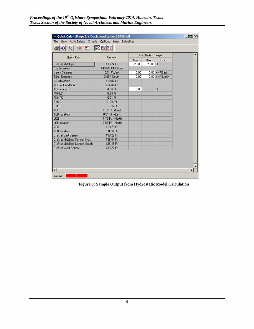
1. Hydrostatic Marine Model (supplied by Ocean Motions) – this model calculates the facility heel, trim and
inclinations from deck loads, environment, ballast/bilge tanks levels and mooring line lengths. Figure 8 shows a
sample output from hydrostatic model for JSM Stage 2 Operating Condition which has maximum topsides
weight and maximum number of risers.
2. Ocean Motions Converter WinMon software (supplied by BMT) – this software converts the ten deck loads
entered by Instructor to four equivalent fixed location deck loads in the Ocean Motions model. This is done
since there is a limitation in the Ocean Motions model to be able to receive X & Y locations. This program runs
in the background and there is no interaction with the user.
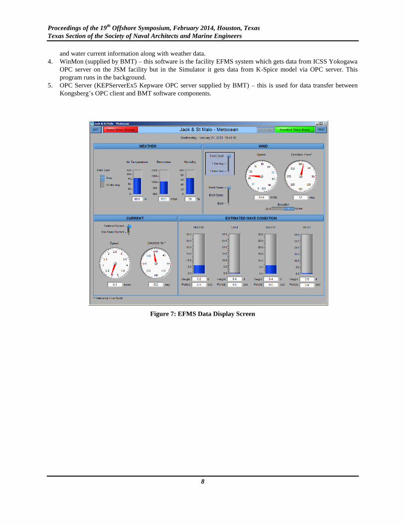
3. EFMS Sensor Simulator (supplied by BMT) – this software simulates any field sensors not available in
Simulator e.g. Ambient temperature, pressure, humidity and other sensors. This program runs in the background
and there is no interaction with the user. Figure 7 below shows a screen from EFMS system displaying wind
Environm
ent, In
clinatio
n,
Position, H
eading
Marine Data
Display
Software
Environment and
Facilities
Monitoring System
(EFMS)
6DOF, Heading, GPS, Airgap,
Wind, Wave, Air Temp &
Pressure, Humidity
Control System
OPC Server
OPC Server
for Sensor
Simulation
Load Management System
Mooring Advisory System
OPC Server
Environment and
Facilities Monitoring
System (EFMS)
All EFMS Data
Inclination, Draft, Mooring TensionOPC Server
For Hydrostatic
Marine Model Data
Trasfer
Deckloads (Manual)
Deckloads, Environment, Ballast, Bilge,
Mooring Line Length
6D
OF
, He
ad
ing
, GP
S,
Airg
ap
, Win
d, A
ir
Te
mp
& P
res
su
re,
Hu
mid
ity
Ballast, Bilge, Void and
Topside Tanks, Draft, Mooring
Line Tension and Length
Deckloads, Environment, Ballast, Bilge,
Mooring Line Length
Inclination, Draft, Center of Rotation, Lat/
Lon, Mooring Tension
Environment and
Facilities
Monitoring System
(EFMS) Sensor
Simulator
Dynamic
Hull Process Model
Hydrostatic Marine
Model (HMM)
All E
FM
S D
ata
Un
ch
an
ge
d
Marine Operator Server
Engineering Server
Student
(Marine Operator)
Instructor
Operator HMI
Co
mm
an
ds,
Da
taB
alla
st,
Bilg
e, V
oid
an
d T
op
sid
e T
an
ks
, D
raft
, M
oo
rin
g L
ine
Te
ns
ion
a
nd
Le
ng
th
Figure 6: Software Architecture - Data Flow
Proceedings of the 19th
Offshore Symposium, February 2014, Houston, Texas
Texas Section of the Society of Naval Architects and Marine Engineers
8
and water current information along with weather data.
4. WinMon (supplied by BMT) – this software is the facility EFMS system which gets data from ICSS Yokogawa
OPC server on the JSM facility but in the Simulator it gets data from K-Spice model via OPC server. This
program runs in the background.
5. OPC Server (KEPServerEx5 Kepware OPC server supplied by BMT) – this is used for data transfer between
Kongsberg’s OPC client and BMT software components.
Figure 7: EFMS Data Display Screen
Proceedings of the 19th
Offshore Symposium, February 2014, Houston, Texas
Texas Section of the Society of Naval Architects and Marine Engineers
9
Figure 8: Sample Output from Hydrostatic Model Calculation
Proceedings of the 19th
Offshore Symposium, February 2014, Houston, Texas
Texas Section of the Society of Naval Architects and Marine Engineers
10
APPLICATIONS
The Marine Simulator for the Jack-St. Malo Facility integrates the process, control system and hull dynamics
for the complete platform, and has proven to be an effective tool for training marine operations, control system I/O
and configuration testing and for practicing various emergency and routine scenarios. It will be used as an Operator
Assessment tool in the near future and during the life of the FPU.
Control System Check-out
The Marine Simulator presents operational information in a form similar to that on the actual facility since the
Control system configuration and Operator graphics used were identical to the actual facility. The Simulator proved
to be an effective tool to perform Control System Check out during pre-commissioning stage well before actual start
up. This control system check-out detected configuration errors in the DCS logic and therefore improved the DCS
implementation, reducing costly commissioning and start-up phases.
Input and output points were connected one at a time from Control system tags to the dynamic process model.
More than 1500 I/O s were connected between the Control system and Dynamic process model. The data transfer
between Control system and process model was done via a custom built link whereas the data transfer with
hydrostatic model was done via OPC.
Control system check-out allowed the simulator to be used to:
Check graphic displays and navigation
Verify Alarm settings and trip set points
Controller tuning
Test motor start/stop logic
Validate permissive logic
Validate cause and effect matrices
Test shut-down & start-up logic sequences
Ballast/Bilge mode operation for pumps
Operator Training
Operator training to operate Jack-St. Malo Ballast and Bilge systems using facility Operator graphics and
control system was thoroughly carried out using Marine Simulator and this contributed to the high level of
confidence in Marine operations including lifts and ballasting operations. The Simulator was used to validate
Standard Operating Procedures before actual facility start-up.
Other than the routine ballasting and de-ballasting operations, listed below are some of the special scenarios
planned for extensive operator training during the life of the FPU –
Environment changes – Wind/Current speed, Wind/Wave/Current direction, Wave height
Damaged compartments due to collision
Inadvertent Flooding of tanks
Mooring line breakage
Transmitter failure
Variable Deck loads
Hurricane Shutdown and Startup
Proceedings of the 19th
Offshore Symposium, February 2014, Houston, Texas
Texas Section of the Society of Naval Architects and Marine Engineers
11
Commissioning and Module Lifts Support
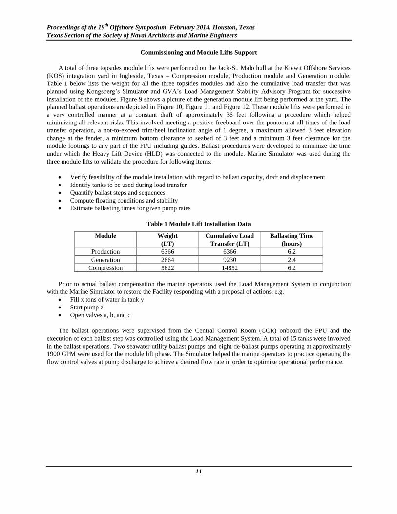
A total of three topsides module lifts were performed on the Jack-St. Malo hull at the Kiewit Offshore Services
(KOS) integration yard in Ingleside, Texas – Compression module, Production module and Generation module.
Table 1 below lists the weight for all the three topsides modules and also the cumulative load transfer that was
planned using Kongsberg’s Simulator and GVA’s Load Management Stability Advisory Program for successive
installation of the modules. Figure 9 shows a picture of the generation module lift being performed at the yard. The
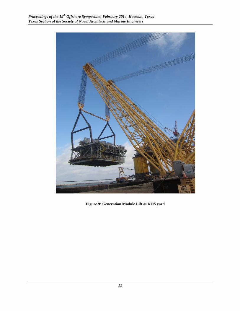
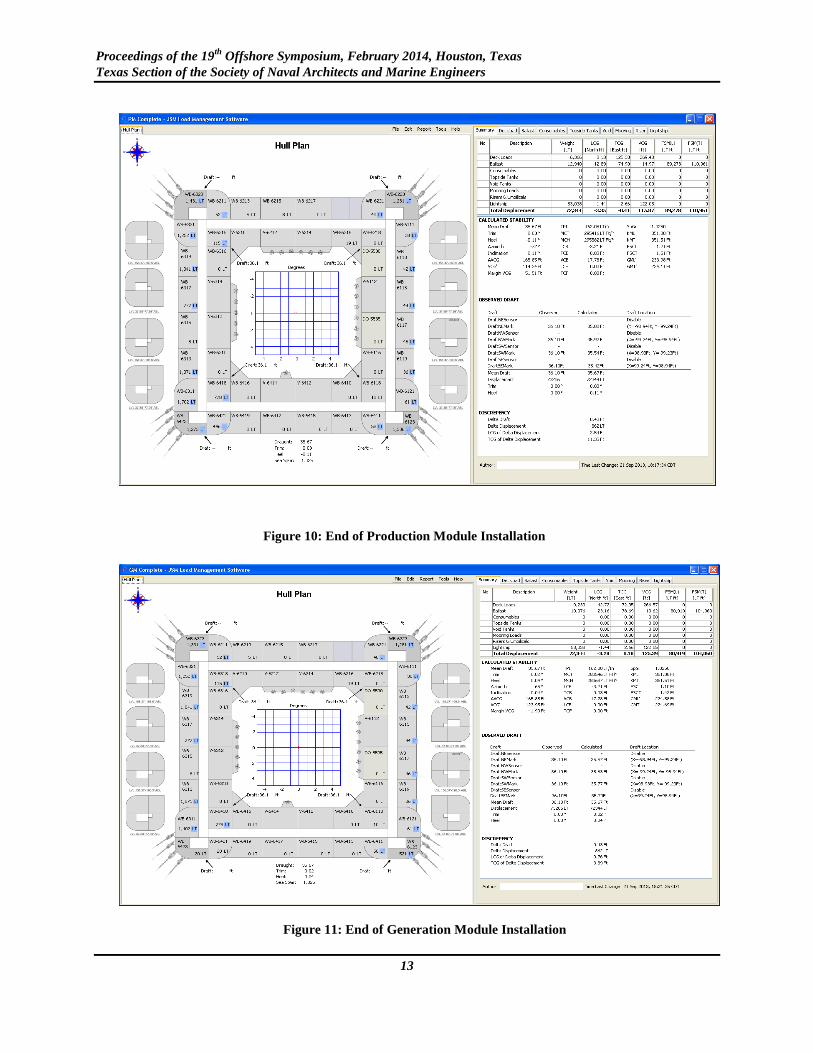
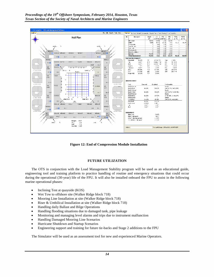
planned ballast operations are depicted in Figure 10, Figure 11 and Figure 12. These module lifts were performed in
a very controlled manner at a constant draft of approximately 36 feet following a procedure which helped
minimizing all relevant risks. This involved meeting a positive freeboard over the pontoon at all times of the load
transfer operation, a not-to-exceed trim/heel inclination angle of 1 degree, a maximum allowed 3 feet elevation
change at the fender, a minimum bottom clearance to seabed of 3 feet and a minimum 3 feet clearance for the
module footings to any part of the FPU including guides. Ballast procedures were developed to minimize the time
under which the Heavy Lift Device (HLD) was connected to the module. Marine Simulator was used during the
three module lifts to validate the procedure for following items:
Verify feasibility of the module installation with regard to ballast capacity, draft and displacement
Identify tanks to be used during load transfer
Quantify ballast steps and sequences
Compute floating conditions and stability
Estimate ballasting times for given pump rates
Table 1 Module Lift Installation Data
Module Weight
(LT)
Cumulative Load
Transfer (LT)
Ballasting Time
(hours)
Production 6366 6366 6.2
Generation 2864 9230 2.4
Compression 5622 14852 6.2
Prior to actual ballast compensation the marine operators used the Load Management System in conjunction
with the Marine Simulator to restore the Facility responding with a proposal of actions, e.g.
Fill x tons of water in tank y
Start pump z
Open valves a, b, and c
The ballast operations were supervised from the Central Control Room (CCR) onboard the FPU and the
execution of each ballast step was controlled using the Load Management System. A total of 15 tanks were involved
in the ballast operations. Two seawater utility ballast pumps and eight de-ballast pumps operating at approximately
1900 GPM were used for the module lift phase. The Simulator helped the marine operators to practice operating the
flow control valves at pump discharge to achieve a desired flow rate in order to optimize operational performance.
Proceedings of the 19th
Offshore Symposium, February 2014, Houston, Texas
Texas Section of the Society of Naval Architects and Marine Engineers
12
Figure 9: Generation Module Lift at KOS yard
Proceedings of the 19th
Offshore Symposium, February 2014, Houston, Texas
Texas Section of the Society of Naval Architects and Marine Engineers
13
Figure 10: End of Production Module Installation
Figure 11: End of Generation Module Installation
Proceedings of the 19th
Offshore Symposium, February 2014, Houston, Texas
Texas Section of the Society of Naval Architects and Marine Engineers
14
FUTURE UTILIZATION
The OTS in conjunction with the Load Management Stability program will be used as an educational guide,
engineering tool and training platform to practice handling of routine and emergency situations that could occur
during the operational (30-year) life of the FPU. It will also be installed onboard the FPU to assist in the following
marine operational phases:
Inclining Test at quayside (KOS)
Wet Tow to offshore site (Walker Ridge block 718)
Mooring Line Installation at site (Walker Ridge block 718)
Riser & Umbilical Installation at site (Walker Ridge block 718)
Handling daily Ballast and Bilge Operations
Handling flooding situations due to damaged tank, pipe leakage
Monitoring and managing level alarms and trips due to instrument malfunction
Handling Damaged Mooring Line Scenarios
Hurricane Shutdown and Startup Scenarios
Engineering support and training for future tie-backs and Stage 2 additions to the FPU
The Simulator will be used as an assessment tool for new and experienced Marine Operators.
Figure 12: End of Compression Module Installation
Proceedings of the 19th
Offshore Symposium, February 2014, Houston, Texas
Texas Section of the Society of Naval Architects and Marine Engineers
15
CONCLUSIONS
The development and implementation of the Jack-St. Malo high fidelity Lifecycle Marine Simulator was a key
contributing factor to the successful accomplishment of following:
Hull Design and lay-out familiarization
Validation of the design intent, integration and operability of the control system
Validation of the Marine Standard Operating Procedures
Familiarization of Marine Operators to the new control system
Developing Operator skills in a safe and risk-free environment
Pre-startup Trouble Shooting
Improving coordination between Topsides and Marine operations
Assistance during topsides module lifts at the commissioning yard
The above mentioned benefits prove that the Marine Simulator is an effective tool to develop and sustain
operations skills and provide unique safe environment for “hands on” training and engineering support.
ACKNOWLEDGEMENTS
Authors would like to thank everyone in Kongsberg, Chevron, Mustang Engineering, GVA and BMT that were
involved in the design and development of the Jack-St. Malo Marine Simulator. We would also like to thank
Chevron and its partners in Jack-St. Malo field development for granting permission to publish this paper.
REFERENCES
Dziubla, P. W., Nelson, W.S, Lang, P.P., Lindsay, M.S., Sanders D. L. and Shepard, N.H., OTC paper 16572,
“Na Kika’s Dynamic Model Operator Training Simulator”, Offshore Technology Conference, Houston, Texas,
USA, 3-6 May 2004.
Rastogi, Ankur and Sharma, Amit, OTC paper 22025, “Operator Training Simulator for KG-D6 Field”,
Offshore Technology Conference, Houston, Texas, USA, 2-5 May 2011.