Embed Size (px)
Citation preview

Marine Safety Investigation Unit
MARINE SAFETY INVESTIGATION REPORT
Safety investigation into the engine-room fire on board
the Maltese registered supply vessel
GSP PERSEU
at GSP Shipyards, Agigea, Constanta, Romania
on 29 September 2014
201409/035
MARINE SAFETY INVESTIGATION REPORT NO. 24/2015
FINAL

ii
Investigations into marine casualties are conducted under the provisions of the Merchant
Shipping (Accident and Incident Safety Investigation) Regulations, 2011 and therefore in
accordance with Regulation XI-I/6 of the International Convention for the Safety of Life at
Sea (SOLAS), and Directive 2009/18/EC of the European Parliament and of the Council of 23
April 2009, establishing the fundamental principles governing the investigation of accidents
in the maritime transport sector and amending Council Directive 1999/35/EC and Directive
2002/59/EC of the European Parliament and of the Council.
This safety investigation report is not written, in terms of content and style, with litigation in
mind and pursuant to Regulation 13(7) of the Merchant Shipping (Accident and Incident
Safety Investigation) Regulations, 2011, shall be inadmissible in any judicial proceedings
whose purpose or one of whose purposes is to attribute or apportion liability or blame, unless,
under prescribed conditions, a Court determines otherwise.
The objective of this safety investigation report is precautionary and seeks to avoid a repeat
occurrence through an understanding of the events of 29 September 2014. Its sole purpose is
confined to the promulgation of safety lessons and therefore may be misleading if used for
other purposes.
The findings of the safety investigation are not binding on any party and the conclusions
reached and recommendations made shall in no case create a presumption of liability
(criminal and/or civil) or blame. It should be therefore noted that the content of this safety
investigation report does not constitute legal advice in any way and should not be construed
as such.
© Copyright TM, 2015.
This document/publication (excluding the logos) may be re-used free of charge in any format
or medium for education purposes. It may be only re-used accurately and not in a misleading
context. The material must be acknowledged as TM copyright.
The document/publication shall be cited and properly referenced. Where the MSIU would
have identified any third party copyright, permission must be obtained from the copyright
holders concerned.
MARINE SAFETY INVESTIGATION UNIT
Malta Transport Centre
Marsa MRS 1917
Malta

iii
CONTENTS
LIST OF REFERENCES AND SOURCES OF INFOMRATION .......................................... iv
GLOSSARY OF TERMS AND ABBREVIATIONS ................................................................v
SUMMARY ............................................................................................................................. vi
1 FACTUAL INFORMATION .............................................................................................1 1.1 Vessel, Voyage and Marine Casualty Particulars .......................................................1 1.2 Description of Vessel .................................................................................................2 1.3 Crew Members and Watchkeeping Arrangements .....................................................3
1.3.1 Crew members ........................................................................................................3 1.3.2 Watchkeeping arrangements in the shipyard ..........................................................4
1.4 Fire-Fighting Equipment in the Engine-Room ...........................................................4 1.5 Environment ...............................................................................................................6 1.6 Location of Steelworks ...............................................................................................6 1.7 Narrative .....................................................................................................................8 1.8 Damages ...................................................................................................................11 1.9 Safety Management System Documentation ............................................................13
2 ANALYSIS .......................................................................................................................15 2.1 Purpose .....................................................................................................................15 2.2 The LEV System ......................................................................................................15 2.3 Cause of Fire.............................................................................................................17 2.4 Fire Patrol and Fire Watches ....................................................................................19
3 CONCLUSIONS ...............................................................................................................22 3.1 Immediate Safety Factor ...........................................................................................22 3.2 Latent Conditions and other Safety Factors .............................................................22 3.3 Other Findings ..........................................................................................................22
4 ACTIONS TAKEN ...........................................................................................................23 4.1 Safety Actions Taken During the Course of the Safety Investigation ......................23
LIST OF ANNEXES ................................................................................................................25

iv
LIST OF REFERENCES AND SOURCES OF INFORMATION
Crew members MV GSP Perseu
Health and Safety Authority. (2014). Local exhaust ventilation (LEV) guidance.
Retrieved from www.hsa.ie on 06 February 2015
Managers MV GSP Perseu
Occupational Safety and Health Administration. (2009). Shipyard industry standards.
Retrieved from www.osha.gov on 06 February 2015

v
GLOSSARY OF TERMS AND ABBREVIATIONS
AB Able Seaman
BHP Brake Horse Power
BV Bureau Veritas
CO2 Carbon Dioxide
DG Compartment Diesel Generators Compartment
DPA Designated Person Ashore
GST Grup Servicii Petroliere S. A.
EEBDs Emergency Escape Breathing Devices
gt Gross Tonnage
HSEQ Health, Safety, Environmental Quality
LEV Local Exhaust Ventilation
LT Local Time
m Metres
m2 Square metres
mm Millimetres
MP Compartment Main Engine-room
mt Metric Tonnes
OOW Officer of the Watch
PC Compartment Power Control Compartment
Rpm Revolutions Per Minutes
SMS Safety Management System

vi
SUMMARY
At 20301 on 29 September 2014, a fire broke out in the engine-room of the supply
vessel GSP Perseu, which was under repairs at GSP Shipyards, at Agigea, Constanta,
Romania.
The safety investigation concluded that the fire was a result of possible hot works
(steel cuttings) being carried out by shipyard‟s workers in way of bilge tank located
aft of the engine room compartments during the night shift on 29 September 2014.
The fire broke out in the main engine-room, aft port side and was first noticed by the
engine-room watchman who initially tried to put out the fire on his own, by means of
a portable CO2 fire extinguisher. The fire was eventually extinguished during the
early hours of 30 September following the release of the fixed CO2 system of the
vessel into the main engine-room.
In view of the safety actions taken by the Company during the course of the safety
investigation, no recommendations have been issued.
1 Vessel‟s time is GMT+3.
2 During MSIU‟s visit on board, the CO2 bottles were ashore for refilling.

1
1 FACTUAL INFORMATION
1.1 Vessel, Voyage and Marine Casualty Particulars
Name GSP Perseu
Flag Malta
Classification Society Bureau Veritas
IMO Number 9083160
Type Supply vessel
Registered Owner GSP Perseu Ltd
Managers Grup Servicii Petroliere S.A.
Construction Steel (Double bottom)
Length overall 60.92 m
Registered Length 56.37 m
Gross Tonnage 1289
Minimum Safe Manning 11
Authorised Cargo Solid
Port of Departure Not Applicable
Port of Arrival Constanta, Romania
Type of Voyage Not Applicable
Cargo Information Not Applicable
Manning 14
Date and Time 29 September 2014 at 2030 (LT)
Type of Marine Casualty Serious Marine Casualty
Place on Board Ship – Engine-room
Injuries/Fatalities None
Damage/Environmental Impact None
Ship Operation In Shipyard
Voyage Segment Alongside
External & Internal Environment Clear skies with a Southerly Force 3 winds. Air
temperature was recorded at 15°C.
Persons on Board Six excluding shipyard workers
2
1.2 Description of Vessel
GSP Perseu (Figure 1) is a 1,289 gt supply vessel built at Braila Shipyards, Romania,
in 1992. The vessel is owned by GSP Perseu Limited, managed by Grup Servicii
Petroliere S. A. (GSP) of Romania and classed with Bureau Veritas (BV).
Figure 1: MV GSP Perseu
GSP Perseu has a length overall of 60.92 m, her moulded breadth is 13.59 m and her
moulded depth is 5.45 m. The deck cargo area, which measured 210 m2, has a
carrying capacity of 460 mt. Being a supply boat, the vessel is equipped with
numerous deck machinery, including tugger winches, capstans and mooring winches.
Propulsive power is provided by two 12V251F Alco Resita four stroke, single acting
diesel engines (Vee configuration), each developing 2,465 bhp at 1000 rpm. Each
engine drives a single, four-bladed fixed pitch propeller (in nozzle), 2410 mm in
diameter. GSP Perseu has a service speed of 11 knots.
The vessel‟s engine-room comprises of three compartments, i.e., the Power Control
Compartment (PC Compartment), located forward of the Diesel Generators
Compartment (DG Compartment), where three diesel generators and other auxiliary
equipment of the vessel are fitted, and the Main Engine-room (MP Compartment).
The main engines are fitted in the MP Compartment below the main deck (Figure 2).
3
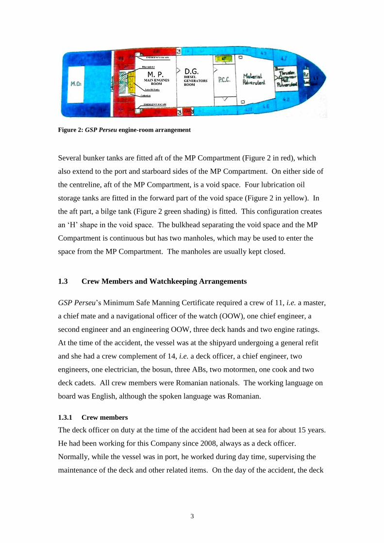
Figure 2: GSP Perseu engine-room arrangement
Several bunker tanks are fitted aft of the MP Compartment (Figure 2 in red), which
also extend to the port and starboard sides of the MP Compartment. On either side of
the centreline, aft of the MP Compartment, is a void space. Four lubrication oil
storage tanks are fitted in the forward part of the void space (Figure 2 in yellow). In
the aft part, a bilge tank (Figure 2 green shading) is fitted. This configuration creates
an „H‟ shape in the void space. The bulkhead separating the void space and the MP
Compartment is continuous but has two manholes, which may be used to enter the
space from the MP Compartment. The manholes are usually kept closed.
1.3 Crew Members and Watchkeeping Arrangements
GSP Perseu‟s Minimum Safe Manning Certificate required a crew of 11, i.e. a master,
a chief mate and a navigational officer of the watch (OOW), one chief engineer, a
second engineer and an engineering OOW, three deck hands and two engine ratings.
At the time of the accident, the vessel was at the shipyard undergoing a general refit
and she had a crew complement of 14, i.e. a deck officer, a chief engineer, two
engineers, one electrician, the bosun, three ABs, two motormen, one cook and two
deck cadets. All crew members were Romanian nationals. The working language on
board was English, although the spoken language was Romanian.
1.3.1 Crew members
The deck officer on duty at the time of the accident had been at sea for about 15 years.
He had been working for this Company since 2008, always as a deck officer.
Normally, while the vessel was in port, he worked during day time, supervising the
maintenance of the deck and other related items. On the day of the accident, the deck

4
officer signed on board during the morning and remained on the vessel after the day
work hours until after the accident.
The chief engineer had been at sea for about 34 years. He served as a chief engineer
for 14 years. He had been working as chief engineer with the Company since 2005.
While in port, he normally worked during day time, overseeing the maintenance of the
main engines and other machinery. During this particular refit, the chief engineer was
overseeing the maintenance and overhauling of the starboard side main engine. On
the day of the accident, he signed on the vessel during the morning and remained on
board after the working hours being present during the accident.
The second engineer had been at sea for about 16 years. He had been a second
engineer for about eight months. He had been working for this Company since 2011
as a second engineer. In port, the second engineer was normally on day work,
overseeing the maintenance of the main engines and other machinery. During this
particular refit, he was tasked to assist the chief engineer with the maintenance and
overhauling of the starboard side main engine.
1.3.2 Watchkeeping arrangements in the shipyard
Evidence suggested that since the vessel‟s entry into the shipyard, all crew members
were working during daytime, mainly on the deck and in the engine-room. At the end
of the daytime hours, a deck watch was maintained by one of the ABs. The AB used
to stay near the accommodation ladder, controlling the access to the ship. His deck
watch also included rounds on the vessel, and the accommodation block. Watches
were maintained on a 24-hour basis. The engine-room watch was kept by an engineer
officer and one motorman who had to remain on board to carry out random safety
tours in the machinery spaces throughout the night.
1.4 Fire-Fighting Equipment in the Engine-Room
The main fire-fighting equipment fitted in the engine-room is a fixed CO2 system,
comprising of a battery of 27 CO2 bottles (Figure 3). The CO2 system was last
inspected by an authorised firm on 20 March 2014. The CO2 battery is fitted in the
CO2 room, located on the aft port side of the accommodation block with direct access

5
to the main deck. The release of the CO2 is operated from inside the CO2 room. The
CO2 battery had been released during the fire-fighting operations2.
Figure 3: CO2 fixed fire-fighting system (following the refilling after the accident)
In addition to the above, the engine-room space is equipped with a number of portable
dry powder and CO2 fire extinguishers. These were last inspected / tested by an
authorised firm on 20 March 2014. The engine-room space is also provided with two
high expansion foam fire-fighting systems, each fitted in every engine-room
compartment and each consisting of two bottles filled with 45 litres of foam. The
installation was last tested / certified by an authorised firm on 25 February 2014.
The vessel is also provided with a fixed water system with fire hoses and relevant
fittings at various locations around the vessel in accordance with the onboard fire
plan. There are two main fire pumps driven by electric motors, in separate engine-
2 During MSIU‟s visit on board, the CO2 bottles were ashore for refilling.

6
room compartments, and an emergency fire pump, which is located remotely from the
engine-room.
The vessel is protected by a fire detection system, which is provided with various
smoke detectors and manual call points, located at various positions around the vessel,
including the engine-room and heat detectors in the DG Compartment. At the time of
the accident, this system was not working since it had been deactivated some days
before.
GSP Perseu has two complete sets of firemen‟s outfits in accordance with the relevant
requirements of the SOLAS Convention. One of the outfit is located in the
wheelhouse and the other one is on the main deck in close proximity of the entrance
to the engine-room. A total of six Emergency Escape Breathing Devices (EEBDs) are
available on board, located at various places around the vessel, including the engine
control room.
1.5 Environment
The weather conditions on the day of the incident were normal with clear skies and
Southerly Force 3 winds. Air temperature was recorded at 15°C.
1.6 Location of Steelworks
The shipyard workers were carrying out steelworks in way of tank nos. 2.7 and 6.1.
As indicated in Figure 4, tank no. 6.1 is situated within the „H‟ shape cofferdam. In
the forward ends (port / starboard sides) of the cofferdam, there are manholes which
are further connecting the cofferdam to the MP Compartment. The covers of these
manholes were open during the hot works in way of tank no. 6.1, while a Local
Exhaust Ventilation (LEV) system was in rigged in place to ensure adequate
ventilation to the shipyard workers during the hot works.

7
Figure 4: Tank plan showing the ventilation duct (red line) as arranged by the shipyard workers
The fitted LEV system comprised of plastic ducting and an electric exhaust fan. The
entry hood for hot works residues / smoke suction of the flexible ventilation duct was
placed inside tank no. 6.1, with the flexible ventilation duct running across the
cofferdam, passing the MP Compartment, through the port side manhole and ending
at an electric extraction fan, which was placed near the port side emergency exit door
to discharge the exhaust air from inside tank no. 6.1.
In addition to the above arrangement, the deck was cut right above tank no. 6.1 in
order to provide natural ventilation of the working space and access to the space
(Figure 5).
Figure 5: Access to tank no. 61 from the deck

8
1.7 Narrative
On the day of the accident, the vessel was stern moored at the shipyard, located in
Constanta South, Agigea port, Romania. The vessel had been berthed at the same
position since 11 September 2014. The work by the shipyard workers in the area of
the fire (near the bilge tank no. 6.1), commenced on 25 September 2014. The work
mostly involved the renewal of steel. The deck crew was engaged with various
maintenance works in way of the deck fittings while the engine-room crew was
engaged with various works in the engine room and particularly with the overhauling
of the starboard side main engine.
On the day of the accident, both the master and the chief mate were not on board since
they were engaged on another vessel owned by the same Company. Six new crew
members signed on board, i.e. one deck officer, the chief engineer, two ABs, one
motorman and the cook, bringing the total crew onboard to 14 persons; one deck
officer, the chief engineer, two engineers, the electrician, the bosun and three ABs,
two motormen, one cook and two deck cadets.
During daytime, the work on board progressed uneventful, including the work carried
out by the shipyard workers. Late in the afternoon, at around 1800, the shipyard
repair team left the vessel after terminating their day of work.
Since the majority of vessel's crew members had just joined the ship, they remained
on board with the officers doing some paperwork. One of the two ABs stood watch at
the access ladder of the vessel, whilst the motorman stood watch in the engine-room.
The engine-room watch was also carrying out random safety rounds, especially after
the shipyard workers had left.
Later during the afternoon, at approximately 1900, another team of shipyard workers
arrived on board in order to continue with the work being carried out by the previous
team. The chief engineer recalled that since they did not carry the necessary
documentation and given that he was not informed of this work which was due to be
carried out during the night shift, he did not authorise the workers to resume their
work. The chief engineer, however, acceded to their request to access the area where
the steel works were being carried out to collect the tools.

9
At approximately 2030, the engine-room watchman noticed smoke coming from the
MP Compartment. Upon seeing this, he requested the shipyard workers to leave the
vessel. Soon after, he saw flames coming out of the aft part of the main engine-room
in the level of the floor plates on the port side (Figure 6). He recalled grabbing one of
the portable CO2 fire extinguishers and tried to extinguish the fire on his own.
Figure 6: Area where the fire was first observed
Seeing that he was unsuccessful, he subsequently notified the deck watchman in order
to warn the rest of the crew members of the fire. The deck watchman proceeded to
the accommodation to warn the rest of the crew. He then ran to the wheelhouse and
activated the fire alarm.
When the chief engineer arrived in the machinery space, he could not see any open
flames but only black smoke. He ordered the crew to isolate the electric power, close
the ventilators to the engine-room and to start the fire pump. Together with the
motorman, he then entered the engine-room with a fire hose; however, they were
forced to abandon the attempt as the smoke was too dense.
Following that attempt, they both donned a breathing apparatus set and entered again
the engine-room in order to locate the seat of the fire. By that time, the engine-room

10
compartments had been engulfed in black smoke and the chief engineer and the
motorman had to leave again, closing behind them the watertight door to isolate the
space.
At about 2130, the chief engineer called the Company‟s Designated Person Ashore
(DPA) and advised him of his intention to activate the fixed CO2 system to extinguish
the fire. However, at that time, the local fire brigade arrived near the vessel and the
person in charge requested the chief engineer not to activate the CO2 system but to
open / ventilate the engine-room for the firemen to access the space, evaluate the
situation and try to extinguish the fire. Moreover, the crew members were requested
to proceed ashore.
Indeed, the ventilation was opened and the firemen entered the engine-room with fire
hoses, water and foam. However, the black smoke had intensified again and after a
number of attempts to extinguish the fire and reduce the smoke, the firemen exited
from the machinery space. With the assistance of the crew, the machinery spaces
were sealed again. The CO2 system was eventually released at approximately 2330.
Another vessel, which was stern moored nearby, the MV GSP Licorn, provided
boundary cooling on the deck and port side of GSP Perseu.
The firemen waited for about two hours whereupon together with the chief engineer,
they went down to the DG Compartment. They observed that there was no smoke
coming out of the watertight door. The firemen entered the space and started cooling
down the space with their fire hoses.
At around 0200 (30 September 2014), the firemen confirmed that the fire was
extinguished and subsequently left the vessel.
The crew proceeded with the ventilation of the space and continuous watch in the
engine-room spaces until the following morning.

11
1.8 Damages
A damage survey was carried out by the BV Surveyor on 01 October 2014. The
following damage was identified:
electrical cables under the main deck affected by the fire and required
replacement;
electrical junction boxes affected by the fire and required replacement;
one electrical panel and monitoring devices affected by the fire and required
renewal;
light fittings affected by the fire and required replacement;
forward seal on the port side tailshaft required replacement; and
smoke damage in various areas of the engine-room.
The damage was localised in the main engine area (Figures 7 and 8) and overhead
cables and insulation (Figure 9).
Figure 7: Fire damage in way of one of the main engines

12
Figure 8: Remaining supporting wire for the LEV ducting
Figure 9: Fire and smoke damages

13
1.9 Safety Management System Documentation
In accordance with the Company's Safety Management System Manual (SMS
Manual), a written agreement was required between the Company and the Shipyard to
address mutual responsibilities related to safety procedures (Figure 10). Evidence
collected during the course of the safety investigation suggested that these relevant
agreements were not in place. However, the following documents had been issued:
Hot Work Certificate (issued on 25 September 2014) [Annex A]; and
Work Permits for 25, 26, 27 and 29 September 2014 [Annex B].
Figure 10: Extract from the Company’s SMS Manual
The Hot Work Certificate only covered the relevant works being carried out in
designated tanks nos. 2.7 and 6.1. Moreover, the work permit (issued on a daily
basis) provided a general description / location of the work, namely “works in tanks”,
and which were supposed to start at either 0700 or 0800 and were valid for up to
maximum of 12 hours. According to this document, the permission to start the works
on board had to be obtained from the second engineer who was signing these

14
documents. The work permit valid for the date of the accident envisaged
commencement of relevant works at 0700, for a duration (permit validity) of 12 hours,
i.e. until 1900. The document was signed by the second engineer.

15
2 ANALYSIS
2.1 Purpose
The purpose of a marine safety investigation is to determine the circumstances and
safety factors of the accident as a basis for making recommendations, to prevent
further marine casualties or incidents from occurring in the future.
2.2 The LEV System
The scope of fitting LEV systems is to capture airborne contaminants at the point of
generation, preventing inhalation by workers in the vicinity. Choosing the proper
type of ventilation is critical in effectively protecting workers from hazardous
airborne contaminants that are normally generated by the various hot work operations
performed during the repairs of vessels. Adequate and safe ventilation may be
achieved with the support of mechanical ventilation (natural ventilation alone would
not suffice to provide efficient means of ventilation in confined spaces as the one
under review). The method is based on the principle that air moves from an area of
high pressure to an area of low pressure. The difference in pressure is created by a
fan that draws or sucks air through the ventilation system.
Mechanical ventilation provided by GSP Shipyards was of the LEV type. LEV is, in
fact, the recommended ventilation method when there is a risk for workers to be
exposed to hazardous chemicals and / or when a large amount of dust and welding
fumes are generated.
For welding, cutting and heating processes, an LEV system would include freely
movable hoods placed by the welder or burner as close as possible to where the work
is being performed in order to „trap‟ the contaminants generated by the hot works and
before they can be released into the work area. The flexible ventilation ducting also
has to be of the right specifications vis-à-vis type / material / length. The ducting
leads to an exhaust fan, which provides the suction power and also to discharge the
collected air / contaminants from the space. Hazards may be created if the material
used for the flexible ventilation ducting is not fit for the purpose.

16
There are a number of considerations which need to be made before an LEV system is
put in place:
1. the ventilation ducting must be flexible but rigid so that it does not collapse
under negative pressure. Usually, the LEV flexible ducting is supported by a
spring-wound frame covered by a fire-retardant material to form the duct.
Ducts made of ordinary polyethylene or other non fire-retardant plastics are
not fit for hot work since the tubing can melt if slag or sparks are drawn inside
and flammable debris is transferred with the hot air flow. Although usually
this type of ducting maintains shape allowing maximum airflow, sharp bends
should be avoided as otherwise the flow of air can be blocked. While a
blocked duct can be dangerous to the workers in the space, it may result in a
serious fire hazard;
2. the length of the flexible ventilation ducting may also be an issue to ensure the
greatest amount of air flow. The hose or ductwork should not be excessive so
as not to affect the efficiency of volume of air being drawn from the space;
and
3. the correct positioning of the exhaust fan is essential. If the fan is incorrectly
placed so that a major section of the ducting is under positive pressure, the
effectiveness of the system is impaired. Poor selection of the exhaust point
may cause the contaminants to be captured by the air supply system; for
instance, instead of being exhausted and diluted, the exhaust air may encounter
a downdraught coming from the open air and re-enter the workplace.
The evidence collected by the MSIU revealed that the LEV fitted by the shipyard had
the following safety issues:
The flexible ventilation ducting used was not made of a fire-retardant material;
The way the flexible ventilation ducting was laid through the various spaces
may have potentially created an obstruction to the flow of exhaust air due to
the various sharp bends in way of the engine room entrance;
The overall length of the flexible ventilation ducting, running from the entry
hood to the exhaust fan was approximately 12 m. This length may have
reduced the efficiency of the system for the extraction of the air flow; and

17
The installation of the exhaust fan within the MP Compartment may have
prevented the efficient expulsion of the exhaust air, given that the exhaust air
outlet was placed within the MP Compartment, albeit close to the open door of
the MP Compartment Emergency Exit.
2.3 Cause of Fire
The safety investigation concluded that in all probability, the fire started from the
plastic flexible ventilation ducting which was used for the LEV system. The flexible
ventilation ducting was running from the cofferdam all the way to the MP
Compartment. Of particular importance was a sharp double loop of the plastic
flexible ventilation ducting, which was located within the cofferdam / engine-room
opening. The double loop was arranged as such to secure the flexible ventilation
ducting (Figure 11).
As indicated in Figure 11, the flexile ducting had a downward bend immediately after
exiting the cofferdam to pass behind two metal pipes and then looped again to pass
above the metal pipes and then continued running on the floor of the engine-room
until its connection to the exhaust fan placed near to the emergency exit of the MP
Compartment.
Figure 11: Representation of how the ducting was routed through the spaces

18
It was not excluded that the double bend created airflow resistance of hot air and hot
work particles, eventually leading to the flexible ventilation ducting catching fire
(Figure 12).
Figure 12: Seat of fire - the double bend of the ducting material
The fire from the burning flexible ventilation ducting then spread to the electric cables
on the deckhead to the port forward side of the cofferdam and the aft port side of the
MP Compartment from where it was further propagated to the forward and starboard
side of the main engine-room as well as to several other areas3.
This scenario raised one question. The MSIU had been informed that the first team
had stopped working at about 1800, which was a normal practice. Thus, if the fire
had started in the LEV system ducting due to the issue discussed above, it meant that
hotwork was actually being carried out at the time.
As indicated elsewhere in this safety investigation report, a second team from the
shipyard came on board to continue the work in the area at about 1900. The MSIU is
aware that at the time of the fire, the second team had not yet left the ship. Their
whereabouts were not controlled by the crew members. However, it was not excluded
that work in the space had resumed by the shore workers until the fire was actually
detected by the duty crew member.
3 Vide sub-section 1.8 for a list of damages.

19
2.4 Fire Patrol and Fire Watches
The fire detection system had been deactivated for a number of days. Consequently,
the crew members were unaware that there was a fire on board, until the duty crew
member observed the smoke during his visit to the engine-room spaces. The safety
investigation could not determine when the fire had actually started. However, by the
time it was discovered, there was already significant smoke in the MP Compartment.
It may be stated that since the fire detection system had been deactivated, fire patrols
and fire watches should have been more frequent. It was claimed, in fact, that the
frequency of fire patrols had been increased. It has to be noted, however, that
notwithstanding the increase in frequency of fire patrols, none of the crew members
reported that the second team had resumed the steel work.
It is a concern that a number of accidents which occurred in shipyards and have been
investigated by the MSIU, point to a situation where the crew members on board are
not necessarily fully aware of the work being carried out by the shipyard workers and
for various reasons, communication is not effective4.
Moreover, risk assessments had not been carried out by the vessel given that the work
was being coordinated and affected by the shipyard workers. A risk assessment
document (issued by the shipyard) in Romanian was made available to the MSIU.
The document was dated 29 September 2014. The document made reference to the
availability of fire extinguishers and fire blankets when hot work was to be carried
out. The document also specified that the use of open flames was not allowed unless
the fire protection requirements specified in the document were fulfilled. The
shipyard risk assessment document also specified that entrance into spaces, which
contained flammable or toxic gases was prohibited without gas free and hot work
certificates being first issued.
The risk assessment document, however, made no reference to the type of flexible
ventilation ducting material that had to be used when hot work was being carried out.
Per se, that may be suggestive that the risk of the material catching fire was either not
anticipated (and assessed), or was missed altogether.
4 Vide Safety Investigation Reports 04/2012 and 17/2015.

20
It was observed, however, that after the fire, the flexible ventilation ducting brought
on board was made of fire retardant material and the exhaust fan was placed on the
main deck (Figure 13).
Figure 13: Flexible ducting made of fire retardant material used after the accident

21
THE FOLLOWING CONCLUSIONS AND SAFETY
ACTIONS SHALL IN NO CASE CREATE A
PRESUMPTION OF BLAME OR LIABILITY.
NEITHER ARE THEY LISTED IN ANY ORDER OF
PRIORITY.

22
3 CONCLUSIONS
Findings and safety factors are not listed in any order of priority.
3.1 Immediate Safety Factor
.1 In all probability, the fire started at a sharp double loop on the plastic flexible
ventilation ducting which was used for the LEV system. It was not excluded
that the double bend created airflow resistance of hot air and hot work
particles, eventually leading to the flexible ventilation ducting material
catching fire.
3.2 Latent Conditions and other Safety Factors
.1 The flexible ventilation ducting was not made of a fire-retardant material;
.2 The way the flexible ventilation ducting was laid through the various spaces
may have potentially created an obstruction to the flow of exhaust air due to
the various sharp bends in way of the engine room entrance;
.3 The overall length of the flexible ventilation ducting may have reduced the
efficiency of the system for the extraction of exhaust air;
.4 It was not excluded that work in the space had resumed by the shore workers
without the crew members being aware;
.5 The risk assessment document made no reference to the type of flexible
ducting material which had to be used when hot work was being carried out.
Per se, that may be suggestive that either the risk of the material catching fore
was not anticipated (and assessed), or was missed altogether.
3.3 Other Findings
.1 The installation of the exhaust fan within the MP Compartment may have
prevented the efficient expulsion of the exhaust air;
.2 The fire detection system had been deactivated for a number of days.
Consequently, the crew members were unaware that there was a fire on board,
until the duty crew member observed the smoke during his visit to the engine-
room spaces;

23
.3 At the time of the fire, the space where steel work was being carried out was
not covered by a hot work permit.
4 ACTIONS TAKEN
4.1 Safety Actions Taken During the Course of the Safety Investigation
During the course of the safety investigation, the Company has taken the following
safety actions:
1. All vessels and operational/technical departments have been instructed to
ensure that prior commencing hot work on board any vessel within the fleet,
approval from the Health, Safety, Environmental Quality (HSEQ) Department
is requested and received. Without the approval, hot work can neither be
carried out on board by the crew members nor by the contractor personnel;
2. The „Stop Work Policy‟ on board all vessels as well as within the shore team
has been reinforced so that any on board activity that is considered unsafe is
immediately addressed;
3. The requirement for a written agreement between the Vessel Technical
Operators and the shipyard (addressing all aspects concerning responsibilities
of safety procedures) has been reinforced and adequately implemented within
the Company. Confirmation of compliance from Technical Department is a
Company requirement;
4. All vessels and the Technical Superintendents have been instructed to ensure
that the Fire Detection System on board each vessel is kept operational during
shipyard/dry-docking repairs as required;
5. No work shall be allowed to commence on board by any subcontractor unless
approved by the on board responsible officer and the work is adequately
monitored by a vessel assigned competent crew member. Moreover, the
responsible officer shall check if all the necessary safety precautions have
been taken into account prior to approve the commencement of the work;
6. Whenever a vessel enters in dry-dock/shipyard for major repairs, a technical
superintendent shall be dispatched on board to supervise the planning and

24
execution of such repairs, including checking/ensuring the availability and use
of adequate equipment by the contracted repair team for the task at hand;
7. As the executing shipyard belongs to the same Group, Corporate HSEQ
Director has taken the lead to evaluate and audit the HSEQ aspects of the
activity within the GSP Shipyard in order to evaluate its compliance with the
required safety precautions and requirements; and
8. Basic Safety Training and Advance Safety Training, which is part of the
Company Safety Induction process applicable to all offshore going personnel,
has been revised in order to put a strong emphasis on the Hot Work Procedure
and Task Risk Assessments, in line with Company procedures and
requirements.

25
LIST OF ANNEXES
Annex A Hot Work Certificate (issued on 25 September 2014)
Annex B Work Permits for 25, 26, 27 and 29 September 2014

26
Annex A Hot Work Certificate (issued on 25 September 2014)

27

28

29

30
Annex B Work Permits for 25, 26, 27 and 29 September 2014

31

32

33