Embed Size (px)
Citation preview

TRANSPORT ACCIDENT INVESTIGATION COMMISSION NEW ZEALAND
M A R I N E O C C U R R E N C E R E P O R T
02-203 Harbour tug Purau, loss of control and grounding, Lyttelton 1 March 2002

The Transport Accident Investigation Commission is an independent Crown entity established to determine the circumstances and causes of accidents and incidents with a view to avoiding similar occurrences in the future. Accordingly it is inappropriate that reports should be used to assign fault or blame or determine liability, since neither the investigation nor the reporting process has been undertaken for that purpose. The Commission may make recommendations to improve transport safety. The cost of implementing any recommendation must always be balanced against its benefits. Such analysis is a matter for the regulator and the industry. These reports may be reprinted in whole or in part without charge, providing acknowledgement is made to the Transport Accident Investigation Commission.

Report 02-203
Harbour Tug Purau
Loss of control and grounding
Lyttelton
1 March 2002
Abstract
On Friday 1 March 2002 at about 1130, while assisting a tanker to depart from the Lyttelton oil wharf, the master of the harbour tug Purau lost control and the tug’s stern grounded, causing damage to the starboard propeller and drive shaft. The safety issues identified included:
• poor ergonomics of the propulsion controls on the 2 port company tugs
• incomplete training of staff
• imbalance of the calibration of the propulsion units
• unauthorised persons on board the tug
Safety recommendations were made to Lyttelton Port Company to address the safety issues.
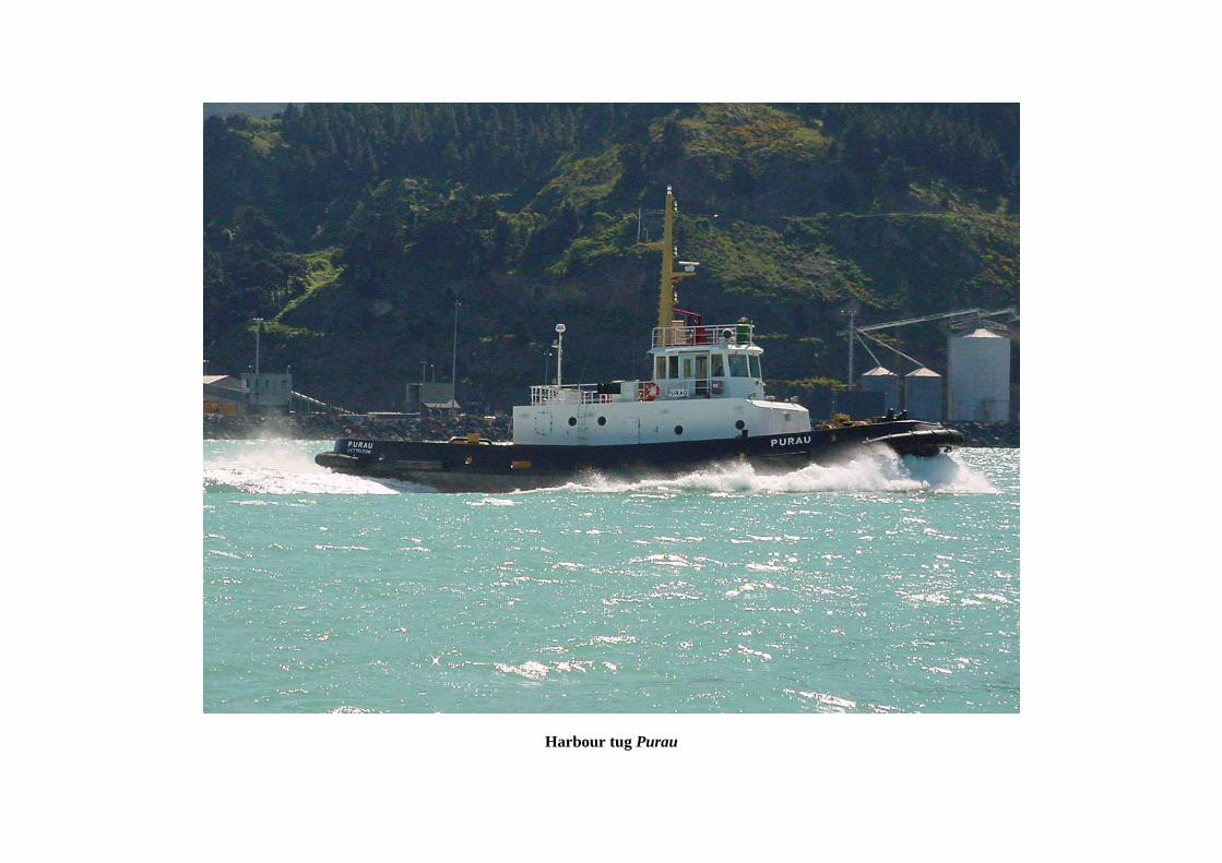
Harbour tug Purau

Report 02-203 Page i
Contents
Abbreviations................................................................................................................................................ ii
Glossary .......................................................................................................................................................iii
Data Summary ............................................................................................................................................. iv
1. Factual information ....................................................................................................................... 1 1.1 History............................................................................................................................ 1 1.2 Tug information ............................................................................................................. 5 1.3 Personnel and training.................................................................................................... 9 1.4 Examination of tug controls and actuators................................................................... 10 1.5 Damage to the tug ........................................................................................................ 12 1.6 Environmental and topographical ................................................................................ 12 1.7 Human factors .............................................................................................................. 12
2. Analysis ....................................................................................................................................... 13
3. Findings ....................................................................................................................................... 15
4. Safety Actions ............................................................................................................................. 16
5. Safety Recommendations ............................................................................................................ 16
Figures Figure 1 Partial chart of Lyttelton harbour ............................................................................................. 2
Figure 2 View of the end of the oil wharf showing where the tug Purau grounded .............................. 3
Figure 3 Starboard unit showing the rock jammed in the propeller........................................................ 4
Figure 4 The control console of the Purau showing the speed control levers on the stops and the wheels opposed. The thrust from each unit is outwards on its respective side.................. 5
Figure 5 Schematic of the electronic/pneumatic control system for the Purau’s Omega clutch and governor .................................................................................................................. 6
Figure 6 Controls of the Godley with the thrust from each unit astern i.e. the tug moving ahead and the speed control levers on idle ............................................................................... 8

Report 02-203 Page ii
Abbreviations ASD azimuth stern drive m metre(s) NZDT New Zealand Daylight Time (UTC + 13 hours) rpm revolution(s) per minute SSM safe ship management UTC Co-ordinated Universal Time
Report 02-203 Page iii
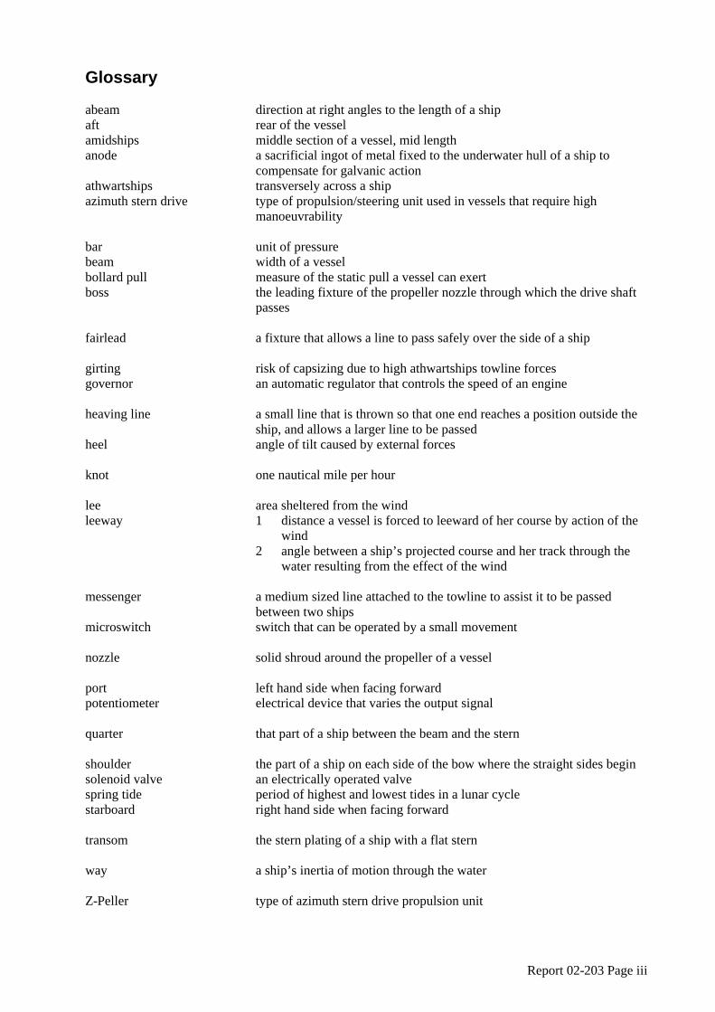
Glossary abeam direction at right angles to the length of a ship aft rear of the vessel amidships middle section of a vessel, mid length anode a sacrificial ingot of metal fixed to the underwater hull of a ship to
compensate for galvanic action athwartships transversely across a ship azimuth stern drive type of propulsion/steering unit used in vessels that require high
manoeuvrability bar unit of pressure beam width of a vessel bollard pull measure of the static pull a vessel can exert boss the leading fixture of the propeller nozzle through which the drive shaft
passes fairlead a fixture that allows a line to pass safely over the side of a ship girting risk of capsizing due to high athwartships towline forces governor an automatic regulator that controls the speed of an engine heaving line a small line that is thrown so that one end reaches a position outside the
ship, and allows a larger line to be passed heel angle of tilt caused by external forces knot one nautical mile per hour lee area sheltered from the wind leeway 1 distance a vessel is forced to leeward of her course by action of the
wind 2 angle between a ship’s projected course and her track through the
water resulting from the effect of the wind messenger a medium sized line attached to the towline to assist it to be passed
between two ships microswitch switch that can be operated by a small movement nozzle solid shroud around the propeller of a vessel port left hand side when facing forward potentiometer electrical device that varies the output signal quarter that part of a ship between the beam and the stern shoulder the part of a ship on each side of the bow where the straight sides begin solenoid valve an electrically operated valve spring tide period of highest and lowest tides in a lunar cycle starboard right hand side when facing forward transom the stern plating of a ship with a flat stern way a ship’s inertia of motion through the water Z-Peller type of azimuth stern drive propulsion unit

Report 02-203 Page iv
Data Summary Vessel Particulars:
Name: Purau
Type: harbour tug
Class: MSA Class IX
LR Class X100A1 TUG + LMC
Allowable passengers: nil
Length: 29.85 m
Breadth: 9.49 m
Gross tonnage: 247 t
Propulsion: two 1103 kW Niigata diesel engines, each driving a shrouded fixed pitch 4-bladed uni-directional propeller
Built: at Nagasaki, Japan in 1986 by Nagasaki Shipyard Company Limited
Owner/operator: Lyttelton Port Company Limited
Crew: 4
Date and time: 1 March 2002, at 11301
Location: Lyttelton
crew: 4 Persons on board: passengers: 3
crew: nil Injuries: passengers: nil
Damage: extensive damage to the starboard propeller and
drive shaft
Investigator-in-charge: Captain D Monks
1 All times in this report are New Zealand Daylight Time (UTC +13 hours) and are expressed in the 24-hour mode.

Report 02-203 Page 1
1. Factual information 1.1 History
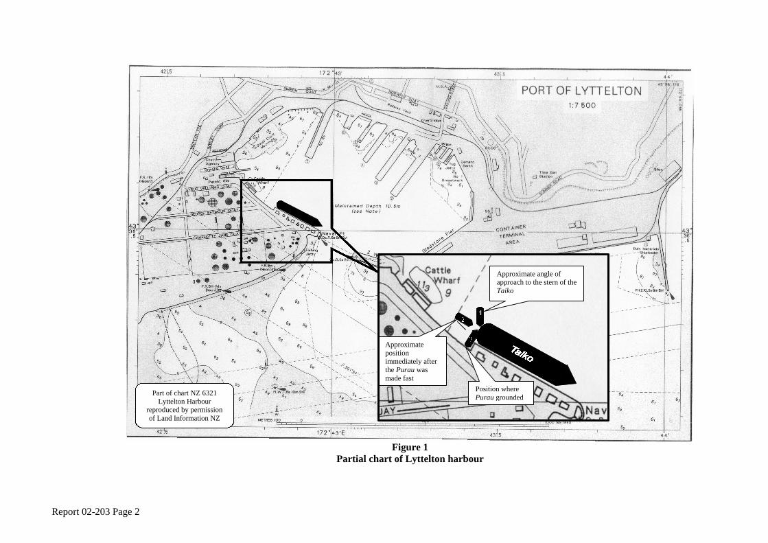
1.1.1 On 1 March 2002, the harbour tug Purau was assigned to assist the tanker Taiko depart from the Lyttelton oil wharf at about 1140 (see Figures 1 and 2). The tug had been ordered for 1130 and the crew had arrived in sufficient time to prepare the tug.
1.1.2 The tug left its berth shortly after 1130 and proceeded directly to the oil wharf. The pilot requested that the master of the Purau put a towline up at the stern of the tanker. The Purau approached the stern of the tanker from its port quarter, at an angle of about 45° to the fore and aft line of the tanker. The tanker’s crew passed a heaving line, to which the tug’s crew tied the messenger that was attached to the towline, which was hauled up to the deck of the tanker. The duty officer at the after mooring station of the tanker and the master of the Purau had a disagreement about which fairlead the towline should be passed through. The tug master left the controls and went out onto the port bridge wing of the tug to reinforce his wish that the towline be passed through the centre fairlead. Eventually, the tanker’s crew complied with the tug master’s request.
1.1.3 While the towline was being made fast, the wind was from the north east, on the port beam of the tug. The effect of the wind was to push the tug to starboard requiring the tug master to adjust the controls to maintain the tug’s bow under the centre of the tanker’s transom. He put the tug in “sideways mode”, where the port unit thrusts out on the port bow and the starboard unit thrusts on the starboard quarter. The “sideways mode” was the best combination of controls to keep the tug in position and allowed it to be propelled bodily sideways by making small adjustments to the direction and speed of one or both units. The prevailing wind and the tug master’s attempt to maintain the bow in the centre of the tanker’s transom caused the tug’s stern to pivot towards the shore that was on its starboard side. The tug master recalled that during the time it took to make the towline fast, the tug had turned through about 45° and was virtually in line with the fore and aft line of the tanker.
1.1.4 When the towline was fast, the tug master still had the controls in the “sideways mode”. He increased the speed control lever on the port unit to propel the tug away from the tanker. The increase in power also propelled the stern to starboard, closer to the rocks on that side. Almost immediately, he heard on the very high frequency (VHF) radio, the pilot order the linesmen to let go the ship’s lines. The tug master realised that the pilot would soon require the tug to pull the tanker’s stern bodily off the wharf. As he was about to adjust the starboard engine speed control to move the tug out to right angles to the tanker’s fore and aft line and level with the stern of the tanker, he heard the revolutions on the port engine start to rise. The increase surprised him as he had not adjusted that engine speed control. He checked the port engine speed indicator, which showed that the speed had increased to almost 500 revolutions per minute (rpm), well above the 400 rpm that would be usual for the setting of the lever. The linesmen on the wharf noted that the tug seemed to go back on its line very quickly and with sufficient speed to cause the tug to heel as the weight came on the towline. The Purau then slewed around on the end of its towline, towards the end of the wharf and the shore.
1.1.5 Assuming that something was wrong with the port unit, and knowing that the tug was very close to the shore, the tug master pulled the port engine speed control back to the adjustable idle stop and turned the azimuth control wheel to zero. In this position, the thrust of that unit pushed out on the port beam and propelled the tug towards the shore. He again checked the port engine speed indicator and noticed that the indicating needle was moving clockwise, showing that the speed was still increasing. He cleared the adjustable idle stop and pulled the port engine speed control back to the “OFF” position to de-clutch the port unit. He turned the azimuth control so that the unit was thrusting astern thus driving the tug ahead and at the same time used the emergency stop button to shut the port engine down. Once the engine was stopped, there was no power to the azimuth motor so the nozzle did not continue turning to the ordered position.
Report 02-203 Page 2
Figure 1
Partial chart of Lyttelton harbour
Position where Purau grounded
Approximate angle of approach to the stern of the Taiko
Approximate position immediately after the Purau was made fast
Part of chart NZ 6321 Lyttelton Harbour
reproduced by permission of Land Information NZ

Report 02-203 Page 3
1.1.6 The tug master could not recall during this period of frenetic action what he did with the starboard unit or what any of the indicators, other than the port engine speed indicator, were showing. While the tug master was trying to overcome the problem with the port unit, the stern of the tug continued to swing to starboard. The tug soon landed its starboard shoulder against the corner pile of the oil wharf, before it came to rest across the end of the oil wharf (at 90° to the fore and aft line of the tanker) with its stern among the rocks on the shore (see Figure 2). The tug master thought that he had de-clutched the starboard unit just before the tug grounded.
1.1.7 Witnesses on the wharf said that at least one engine was running when the tug grounded, there was a graunching noise of rocks in the propeller and muddy propeller wash oscillating from the rocky shore on the port quarter to the port beam of the tug. The engine stopped soon after the tug grounded.
Figure 2 View of the end of the oil wharf showing where the tug Purau grounded
1.1.8 One of the tug crew put a mooring line from amidships up onto the wharf. At this time, the towline was still fast on the tanker but the master of Taiko was concerned for the safety of his ship and ordered that the towline be let go and the tanker re-secured to the wharf. The lack of restraint on the bow of the tug allowed it to swing to the wind until it lay parallel to the steep-to shore. The tug rested alongside the rocks rather than becoming fast aground.
1.1.9 The tug engineer went from the deck, where he had been driving the towing winch, to the engine room where he saw that the engine control panel indicated that the port engine had been shut down on the emergency stop and the starboard engine was showing a “steering hydraulic
Oil wharf
End of the oil wharf, where the Purau landed
Rocks on which Purau grounded

Report 02-203 Page 4
pump trouble” alarm. He later stated that the starboard alarm indicated the propeller had picked up something that had jammed it, for example if a tyre had been drawn into the nozzle.
1.1.10 The master of the Purau requested the pilot boat, Canterbury, which was in the harbour, to come and tow the tug clear of the rocks. The pilot boat pulled the tug clear of the shore and into the middle of the harbour. When clear of the shore, the towline was released so that the tug’s engines could be tested. The starboard engine was started but would not clutch in. Owing to the problem with the port engine during the incident, the tug master did not to try to start it. The pilot boat was called back and towed the tug to its berth.
1.1.11 At about 1230, the other port company tug, the Godley, assisted the tanker to un-berth. That tug was also affected by the wind when it was making fast to the tanker. It too was turned from 45° on the quarter to in line with the ship.
1.1.12 Divers inspected the Purau later that day and found a large rock stuck in the starboard nozzle and significant damage to the starboard propeller blades (see Figure 3). The tug was dry docked the next day.
Figure 3 Starboard unit showing the rock jammed in the propeller
Report 02-203 Page 5
1.2 Tug information
1.2.1 The Purau was a dedicated harbour tug, owned and operated by Lyttelton Port Company Limited. The tug was operated under a safe ship management (SSM) system provided by Lloyds Register of Shipping. Safety and operation manuals were in place and the SSM Certificate that was issued on 21 February 2001, subject to periodic inspections, was to remain in force until 20 February 2006.
1.2.2 The Purau operated with a minimum complement of 4, comprising master, engineer and 2 deckhands. The maximum allowable complement was 7 with lifesaving equipment provided for 8 persons. The SSM Certificate stated that the tug was not permitted to carry passengers.
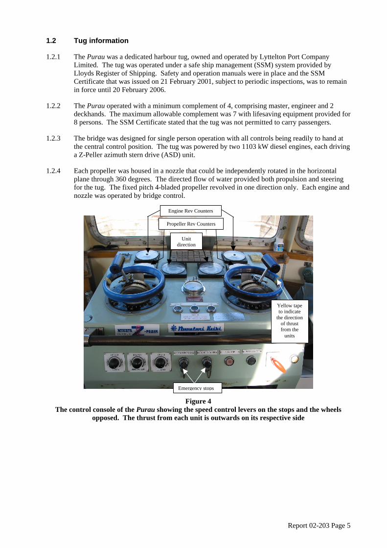
1.2.3 The bridge was designed for single person operation with all controls being readily to hand at the central control position. The tug was powered by two 1103 kW diesel engines, each driving a Z-Peller azimuth stern drive (ASD) unit.
1.2.4 Each propeller was housed in a nozzle that could be independently rotated in the horizontal plane through 360 degrees. The directed flow of water provided both propulsion and steering for the tug. The fixed pitch 4-bladed propeller revolved in one direction only. Each engine and nozzle was operated by bridge control.
Figure 4 The control console of the Purau showing the speed control levers on the stops and the wheels
opposed. The thrust from each unit is outwards on its respective side
Emergency stops
Unit direction
Engine Rev Counters
Propeller Rev Counters
Yellow tape to indicate
the direction of thrust from the
units

Report 02-203 Page 6
Figure 5 Schematic of the electronic/pneumatic control system for the Purau’s Omega clutch and governor
OFF
0
ON
5
10
Ω
Solenoid valve
Solenoid valve
Omega Clutch
Governor
microswitch
microswitch
Control air at 6 Bar
Engine speed control potentiometer and microswitches
Signal to open the clutch
solenoid valve at the
“ON” position
Signal to open the governor solenoid valve
and close the clutch solenoid valve at just
above the “0” position
Pneumatic Servomotor
Report 02-203 Page 7
1.2.5 The steering control for each unit was via a hand wheel on the respective side of the bridge console (see Figure 4), which controlled the direction of the azimuthing nozzles. The engine speed control was a “T” shaped lever in the centre of the steering control wheel. With the units set to propel the tug ahead, the speed control lever was pushed away from the operator to increase the engine speed. The graduations on the speed control lever were:
OFF Omega clutch not engaged ON First microswitch opens and control air is allowed to the Omega clutch - [1] ΩΩ [2] Progressive increase in clutch engagement throughout this range - [3] 0 Second microswitch activates, closing the clutch solenoid valve and leaving the
clutch fully engaged. At the same time the governor solenoid valve opens to allow 5 control air to the governor. Engine speed increases proportionally with the advance of the lever 10 Full speed
1.2.6 The drive train of each propulsion unit included an Omega clutch system. This was a
hydraulically actuated, multiple-disc, wet type clutch that allowed infinitely variable output shaft speeds with a fixed engine input speed. The engine speed throughout the Omega clutch range was set to be constant at 400 rpm but in practice varied between 380 rpm and 400 rpm as the load changed. Electronic signals from a potentiometer connected to the speed control levers, actuated a pneumatic system that included a proportional servomotor, which regulated the amount of control air to the clutch and the engine governor (see Figure 5). There were two microswitches: the first activated when the speed control lever passed the “ON” position; this opened the solenoid valve that allowed control air to regulate the clutch hydraulics. Just after the “0” position on the speed control lever, a second microswitch activated, this opened the solenoid valve that allowed control air to the governor and closed the solenoid valve to the clutch, which then remained fully engaged. The electronic signal and corresponding control air was maximum when the speed control lever was moved to the “ON” position. In that position the clutch was disengaged. As the speed control setting was increased, the signal and the control air decreased, progressively engaging the clutch, until at the “0” position the signal and the control air were zero and the clutch was fully engaged. Once the second microswitch had activated, further increase of the speed control lever increased the signal and the control air to the governor, which increased the engine speed.
1.2.7 If there was a disruption in the supply of control air after the first microswitch had engaged, the clutch would default to fully engaged and the engine would remain at, or if it was above the “0” position, reduce to the idle revolutions setting of 400 rpm. There was no evidence that there was a failure of the control air during this accident.
1.2.8 There were 2 revolution speed indicators for each unit on the console immediately in front of the operator. The upper ones indicated the respective engine speeds and the lower ones the propeller speeds. Two other dials situated above and between the control wheels indicated the direction in which each unit was pointing. To assist the operators yellow tape had been placed on the control wheel to indicate the direction the water was being thrust from the units (see Figure 4). A control air pressure gauge between the two wheels showed the level of air pressure on the steering/propulsion controls.
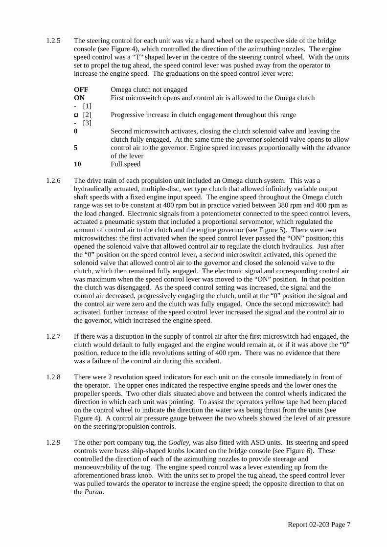
1.2.9 The other port company tug, the Godley, was also fitted with ASD units. Its steering and speed controls were brass ship-shaped knobs located on the bridge console (see Figure 6). These controlled the direction of each of the azimuthing nozzles to provide steerage and manoeuvrability of the tug. The engine speed control was a lever extending up from the aforementioned brass knob. With the units set to propel the tug ahead, the speed control lever was pulled towards the operator to increase the engine speed; the opposite direction to that on the Purau.
Report 02-203 Page 8
1.2.10 Although the propulsion systems for the tugs were similar, the speed at which the machinery responded to the controls was different. On the Purau the units followed the azimuth control wheels with little delay. The azimuth response on the Godley was slower. Changes of engine speed on the Purau were slow, with about a 4-second delay between moving the lever and the engine responding, whereas on the Godley there was an almost instantaneous response.
1.2.11 On each tug the azimuth control included a feature that moved the units the shortest distance to the required setting. For example, an alteration of over 180°, if executed quickly, would result in the unit rotating in the opposite direction to that expected.
1.2.12 The speed control levers on the Purau were free and easily moved. If knocked, they were able to pass the detent at “0” and the momentum of the lever carried it through the whole range of the throttle setting to 10, assisted by the weight of the “T” shaped handle.
Figure 6 Controls of the Godley with the thrust from each unit astern i.e. the tug moving ahead and the
speed control levers on idle
1.2.13 In 1988, there had been a speed control problem with the port engine of the Purau. A service engineer from the propulsion system manufacturer attended the tug at that time but in 1989, the Lyttelton Port Company had requested further information by facsimile, because the port unit was still not operating satisfactorily. In 1991, the Lyttelton Port Company again sent a facsimile to the builder stating that:
The engine speed control of the port engine is causing problems. At half throttle the engine revolutions sometimes increase suddenly from half speed to full speed. The problem is potentially dangerous. Please advise us if a Niigata service engineer is expected in New Zealand. We would like to know whether or not a service engineer plans to be in New Zealand in the next few months.
1.2.14 Other than the two facsimiles mentioned above, there was no other documentation to indicate what the problem was or how it had been resolved. The engineer of the tug at the time of these problems remembered that a circuit board in the port unit control system had been replaced but he was unaware of any other adjustments that may have been made.
Speed lever pulled towards the operator to increase speed
Steering control
Speed Control Levers
Steering control

Report 02-203 Page 9
1.2.15 The Commission asked the propulsion system manufacturer to provide information regarding the repairs and adjustments that were made during the service engineer’s visits to the tug in 1988, 1989 and 1991, but no response had been received at the time of writing the report.
1.2.16 In July 2000, the tug masters noticed a discrepancy between the calibration of the port and starboard units. The tug engineers had taken a set of readings from each engine at various settings between “OFF” and “0”, including engine and propeller speed, governor air pressure, clutch [hydraulic] oil pressure, clutch lube oil pressure, control [servo] air pressure and control [servo] oil pressure. The data collected showed that there were discrepancies between the two engines. On advice from the propulsion system manufacturer, the tug engineers had adjusted the shuttle valve on the port Omega clutch control until the two units gave similar readings.
1.2.17 Four days prior to the grounding, while approaching a ship that was only just making way, another tug master had a problem steering the Purau. He explained that he noticed that the port unit had more propeller revolutions on it than he expected. When he checked the position of the speed control levers he found that instead of being on the adjustable stops, as he thought they were, the port one was about 3 mm above the stop. He pulled that lever back to the stop and the port propeller speed reduced back to normal.
1.2.18 Following the dry dock, sea trials were conducted on the 7 May 2002. It was not possible to replicate the problem experienced four days before the grounding but it was noted that small movements of the port speed control lever resulted in relatively large variations in propeller speed when compared to the starboard.
1.2.19 The removable stops and their adjusting screws had been fitted to the speed control levers soon after the tug arrived in New Zealand. Their purpose was twofold: first to allow the tug masters to equalise the units so that the propeller speed and engine speed were the same on each unit; secondly, to give the masters a definitive known position that they could bring the speed control levers back to without having to look closely at the speed indicators or graduations. The stops made the handling of the tug, particularly at slow speeds, considerably easier than it otherwise would have been.
1.3 Personnel and training
1.3.1 The master of the Purau first went to sea as a deckhand on inshore fishing vessels. Later, he had operated vessels in Australia while working for a salvage and construction company. He returned to New Zealand in 1984 and joined the Lyttelton Port Company (then the Lyttelton Harbour Board) in November 1985. He had started as a diver and then took on duties as a crane driver. Interspersed with those duties, he was also required to relieve as a deckhand on the port’s floating plant, which included a garbage collection vessel, the pilot boat and the dredge. On 1 October 1992, he passed a Commercial Launch Master Certificate and began training as relieving skipper on the pilot boat and he was made permanent skipper in August 1997. He showed an interest in being trained as master of the harbour tugs and volunteered to train on them during his off duty periods. In May 2000, he officially started as a trainee tug master and went through the port company’s training programme.
1.3.2 The port company’s tug master training programme was itemised in a manual. It comprised 6 main parts:
• Familiarisation of Tugs
• Training in Basic Tug Operations
• Port Navigation Knowledge
• Reading and Reference
• Accompanied Tasks
• Job Log

Report 02-203 Page 10
1.3.3 The tug master completed this basic training on 28 August 2000. The majority of the sections in the manual had been completed but there were items that had not been signed off and some had been signed but not dated. Two important items that had not been completed were that he had not read the reference book Tug Use in Port by Captain Henk Hensen and the “Accompanied Tasks” section had not been completed. However, a number of the tasks recorded in the tug master’s “Job Log” were those required in the “Accompanied Tasks” section.
1.3.4 The training manual was not prescriptive about the tasks that the trainee had to complete, how trainees could demonstrate their competence and how the training master should evaluate that competence. The only emergency situation in which the trainee had to show competence was to bring the tug back to the berth on one engine should the other fail. It was possible that other scenarios, such as girting or a broken towline, were covered during the training but this was not obvious from the documentation. There was no reference information on the tugs’ handling characteristics contained in the training manual.
1.3.5 After completing his training, the tug master relieved on the tug roster while maintaining his duties on the pilot boat. In October 2001, he was made a permanent tug master and joined the tug roster.
1.3.6 The tug roster that was in force at the time of the accident appeared complicated but was easily understood when working within the system. The tug masters and engineers worked 17 days in a 28-day period. This was broken down into 3 shifts. An “am” shift between 0000 and 1200, a “pm” shift between 1200 and 0000 and a 24-hour “on call” shift that covered those jobs that required 2 tugs. The tug masters and engineers were only allowed to remain on any one shift for a maximum of 3 days before taking time off. The tug deckhands worked a different shift system of 4 days on the “am” shift while covering the 2-tug jobs on the “pm” shift, 2 days off and then 4 days on the “pm” shift while covering the 2-tug jobs on the “am” shift. To accommodate the rotation of the tug deckhands and to ensure that they were not continuously on the same shift, the tugs themselves were also designated as “am” or “pm” to indicate on which shift they were the first-call tug. The tugs changed designation weekly.
1.3.7 The tug deckhands were only rostered on their designated tug. The tug masters and engineers changed between the 2 tugs on a regular basis. When they were on the 24-hour shift, covering those jobs where 2 tugs were required, they worked the second call tug. Consequently, they would be on the “pm” tug in the morning and the “am” tug in the afternoon. This required that the tug masters be familiar with the different controls and handling capabilities of each tug and be able to adapt from one to the other.
1.3.8 There were 3 unauthorised persons on board at the time of the incident. One was the young son of a crewmember, who remained on the after deck throughout the voyage. The other 2 persons had arrived to service a drinking water cooler just as the tug was about to leave its berth, and had been invited to go along with the tug while it assisted the tanker. They were on the bridge at the time of the grounding but were not talking to the master or otherwise distracting him.
1.4 Examination of tug controls and actuators
1.4.1 After the accident, an electronics technician and a pneumatic engineer checked the control systems. There was no evidence of rust, debris or water in the pneumatic system and no evidence of any air leaks. The servomotors for the port and starboard systems were removed and bench-tested at control air pressures of 2, 4 and 6 bar. A signal, which simulated that from the speed control lever potentiometer, was applied to the port servomotor, which started to open and allowed control air to flow when the control signal was 0.17 amps and was fully open at 0.46 amps. The starboard servomotor operated at similar values. The solenoid valves were tested at the same control air pressures and were cycled 150 times (opened and closed) without faulting. The pneumatic engineer was of the opinion that the servomotors and solenoid valves were operating normally and within the specifications of the pneumatic system.

Report 02-203 Page 11
1.4.2 While the tug was in dry dock the electronics technician checked the electrical signals from the speed control potentiometer. They were found to meet the manufacturer’s specifications.
1.4.3 The governors were removed from the engines and dispatched to a governor specialist for testing. The specialist concluded that:
…no internal faults or operating faults were found that would have resulted in either engine increasing in revolutions.
1.4.4 Repairs were completed on 6 May 2002. Sea trials were carried out the following day with the electronic and pneumatic technicians on board. The tug was taken out to the outer harbour where a number of manoeuvres were carried out to identify the handling characteristics of the tug and the operation of the control systems. During the trials it was noted that:
• The port and starboard units were calibrated differently. Before leaving the berth, the tug master (not the one in command on the day of the accident) adjusted the stops so that the port and starboard speed indicators were reading the same, 400 engine rpm and 100 propeller rpm. One of the operators suggested that the discrepancy that necessitated this adjustment was temperature related; this was not confirmed during the sea trials or subsequent tests. With the levers on the adjustable stops, the port speed control was just under half a graduation above the Ω mark and the starboard speed control was just under half a graduation below the Ω mark. The port speed control lever activated the second microswitch at about two thirds of a graduation before the “0” mark. The starboard speed control lever activated the second microswitch just before the “0” mark.
• While manoeuvring around the inner harbour it was usual for “0” to be the maximum setting. This propelled the tug at a speed of about 8 knots. The Omega clutch range of the speed control setting was often used when manoeuvring in confined situations.
• Once in the open water of the outer harbour, a test was carried out on the port unit to determine what would happen if the speed control lever was accidentally knocked from the stop through to “10” (full speed) before being brought back to the stop. Initially nothing happened but after a delay of about 4 seconds the propeller and engine revolutions started to rise. As soon as the engine revolutions reached about 500 rpm, the handle was returned to the stop. The engine speed indicator needle continued to rise for about a second before falling slowly back to 400 rpm. During this test the propeller speed indicator showed a fall in speed faster than the engine speed indicator.
• Another test was carried out while free running with the speed control levers at the “5” position and the engine speed indicators at about 580 rpm. When the port lever was brought back to the stop, there was a delay of about 2 seconds before the engine speed indicator needle flicked upward before slowly falling back to about 400 rpm.
• With the tug stopped in the water and the units opposed (thrusting out at right angles to the hull on their respective sides) and with the speed control levers on “0”, it was noted that the port engine revolutions and, therefore, the propeller revolutions started to rise. They rose to about 420 engine rpm and 195 propeller rpm. When the tug master jiggled the speed control lever back slightly the revolutions rose further, reaching a maximum of 440 engine rpm and 210 propeller rpm. The imbalance between the two units caused the tug to start turning rapidly, the bow moving to port and the stern to starboard. The tug master pulled both levers back to the stops and the speed of each unit fell to the pre-adjusted level of 400 engine rpm and 100 propeller rpm and the tug stopped turning.
• Further testing was not possible because the turbo charger on the starboard engine malfunctioned and the tug returned to its berth.

Report 02-203 Page 12
1.4.5 The day after the sea trials, the electronic and pneumatic technicians returned to the tug and took measurements of the control air and checked the operation of the microswitches. The position of the second microswitch on each speed control lever mechanism was found to be advanced, that is the switches were actuating before the “0” position. The port actuated about two thirds of a graduation before the “0” position and the starboard just before the “0” position. Each switch was adjusted to the position recommended in the manufacturer’s specifications: a third of a graduation after the “0” position.
1.4.6 The electronics technician concluded that the uncommanded increase in engine revolutions on the port engine was “most certainly caused by the incorrect adjustment of the GSO [speed control] lever clutch/engine micro-switch or worn brass activation cam for this.”
1.5 Damage to the tug
1.5.1 For clarity, positions on the nozzle refer to the unit when it is in the fore and aft line and is thrusting water astern and propelling the tug ahead. When examined in dry dock, the whole circumference of the inner plating of the starboard nozzle had been stripped of paint in way of the propeller and there were scratches that radiated outwards on the paint remaining on the thrust side of the nozzle. The damage on the outside of the starboard nozzle was limited to the lower outboard side of the propeller drive boss and the lower outboard nozzle stay on the suction side of the nozzle. The leading edges of the starboard propeller blades were deeply serrated. The port nozzle outer plating on its inboard side had deep scratches and a sacrificial anode had been torn off. The propeller blades had minor nicks along their leading edges but these might have been pre-existing damage. There was no evidence on the port nozzle that rocks had passed through it.
1.5.2 The hull had a number of areas where the paint had been chipped off, the most severe of which were situated midway between the two propulsion units. There were other smaller and shallower indentations on the hull, from those between the units, forward through an arc of about 90°, within a distance of about 4 m of the starboard propeller nozzle.
1.5.3 When the tug was dry-docked, the port unit was found in a position to thrust out just abaft the port beam.
1.5.4 The only hull damage, other than in the vicinity of the units, were two minor paint scratches amidships on the port side at about one metre below the waterline.
1.6 Environmental and topographical
1.6.1 There was a spring tide at the time of the accident. Low water was predicted at 1310, with a height of 0.1 m above chart datum. It was noted by a number of the witnesses that the water level was particularly low at the time of the accident.
1.6.2 The wind was north to north-east at about 10 knots, with a rippled sea and no swell. The weather was generally fine.
1.6.3 Rocks removed from the port’s bulk coal facility had been tipped along the shore on the western side of the oil wharf, which created the steep rocky shoreline. Following the accident, the port company sounded the area and confirmed that the bottom rose uniformly and steeply from a depth of about 6 metres to the waterline, in a gradient similar to that shown above the waterline in Figure 2.
1.7 Human factors
1.7.1 Stress, attention and workload are three related factors that affect human performance. Stress is the body’s response to stressors and may develop from sources both within the workplace and from the home environment. This is referred to as life stress and can cause a person to become distracted and make it difficult for them to pay attention to the task in hand. When the demands
Report 02-203 Page 13
of certain tasks approach or exceed the capability of the operator, stress develops; this is termed task or acute stress. One of the primary outcomes of the latter type of stress is that the person’s attention becomes channelled and focussed on one task to the exclusion of others.
1.7.2 Channelled attention is a primary symptom of poor situational awareness, which prevents the operator forming an accurate mental model and prevents the correct action being taken to recover from the situation.
1.7.3 Decision making, the assimilation of information before an action is carried out, can be separated into two basic types: analytical and intuitive. Analytical decisions are knowledge-based and primarily made by someone who is competent but not particularly experienced. They tend to be slower and take a large proportion of the available cognitive processes, leaving less time for other tasks. Intuitive decisions are skill-based and are based on experience gained over many years. They are rapid and take less of the available cognitive processes but they are susceptible to biases, which may result in an incorrect decision being made.
1.7.4 Skill or familiarity with equipment developed in one situation, may conflict with that required to master or perform a task in another situation. This is defined as negative transfer. It is most likely to occur when a rapid response must be made to a stimulus in a time of stress. An example of this would be a car driver, who is used to the turn indicator lever being on the right-hand side of the steering column, having to drive another vehicle that has the lever on the left-hand side of the steering column (and the windscreen wipers lever on the right-hand side). When driving normally, under easy driving conditions, the driver will, after a little practice, remember that the lever is on the opposite side to the one they are used to and act accordingly. However, should the driver become distracted or be under pressure, it is probable that when trying to indicate they would operate the windscreen wipers by mistake.
2. Analysis
2.1 Some combination of events caused the port unit to increase in speed.
2.2 It took longer to secure the towline on board the tanker than normal because of the disagreement over which fairlead was to be used. The tug master left his controls and went onto the tug’s port bridge wing to converse with the duty officer on the tanker. While the towline was being made fast, the tug was affected by the wind and was pushed towards the leeward shore. The tug master manoeuvred the tug so that the bow remained under the centre of the tanker’s transom but in so doing the tug’s stern pivoted towards the shore. When the pilot ordered the linesmen to let go the tanker’s mooring lines, the tug master put pressure on himself to get his tug quickly into position.
2.3 The delay in securing the towline and the resultant perceived urgency for the tug master to position his tug to assist the tanker may have caused him to apply more power than he would otherwise have used. This is supported by the reports that the tug moved back onto its line quickly and that it heeled when the weight came on the line.
2.4 During the sea trials on 7 May 2002, the revolutions on the port unit unexpectedly rose when the lever was at the “0” position. The electronics technician discovered that the second microswitch on the port speed control lever was actuating about one graduation before it was designed to and was allowing control air onto the governor thus increasing the speed of the port engine above 400 rpm, before the “0” position. He also noted that the microswitch was likely to have been incorrectly positioned for a period before the accident. Wear and a rough surface was found on the brass cam that activated the microswitch. When manoeuvring the tug, the various masters continually adjusted the speed of the engines and the direction of the nozzles, driving by feel and reacting to the motion of the tug rather than by observing the instruments. Any previous uncommanded increase of speed on the port engine was possibly not noticed or was unconsciously compensated for during normal operations. On the day of the accident, the tug
Report 02-203 Page 14
master said that the port engine had reached a speed approaching 500 rpm immediately before he lost control. This was significantly higher than that obtained during the sea trials.
2.5 The controls and responsiveness of the propulsion and steering systems of the Godley and the Purau were similar but did have significant differences. The tug masters frequently swapped from one tug to the other. It is possible that on this occasion the tug master experienced negative transfer as he came under pressure to get his tug into position to assist the tanker and that resulted in him increasing the speed of the port unit rather than reducing it.
2.6 The speed control levers were free and took very little effort to move them. The detent at “0” was not sufficient to stop a lever that had been knocked going through that position and continuing on to the full ahead position. The cross piece on top of the lever was sufficiently heavy to assist this motion. It is feasible that while trying to check how close the tug’s stern was to the shore, the tug master knocked the control lever up through its range to, or near to, full ahead.
2.7 Whatever caused the increase in speed of the port unit, the tug master appeared to focus exclusively on it, symptomatic of task or acute stress.
2.8 ASD tugs are extremely manoeuvrable. When they are free running they can, in addition to moving ahead and astern, turn within their own length and travel sideways. However, when they are operating in confined waters with the external influence of wind and current it can be difficult to accurately control the movement of the bow and the stern simultaneously. Once the tug is fast and has weight on the towline, the tug master can use this weight to pivot the tug about. In this case, while making fast at the stern of the tanker, the tug master of the Purau, and later the tug master of the Godley, had to adjust the controls to maintain the bow of their tug under the centre of the tanker’s transom to overcome the effect of the wind that was pushing them towards the shore. This resulted in the tug pivoting and its stern moving towards the shore.
2.9 The tug propulsion system was such that the tug master should have been able to overcome the problem with the port unit and manoeuvre the tug away from the shore using the starboard unit alone, particularly once the weight was on the towline to act as a pivot point.
2.10 The SSM manuals adequately covered the normal operations of the tug but did not address the action that should be taken if there was an operational emergency.
2.11 The physical evidence of the damage to the starboard nozzle, the direction of the marks on the adjacent hull and the crushed rock deposits found in them, the way the large rock was jammed in the nozzle and the witnesses’ descriptions of the direction of the propeller wash suggest that shortly before, and immediately after the tug grounded, a unit was thrusting out on the port side, the opposite direction to that required to get the tug out of its situation. As the port unit was already shut down at this time, the wash had to have been from the starboard unit. Shortly before the grounding, the tug master probably turned the starboard steering control wheel through more than 180° causing the unit to take the shortest route to a new position. The unit would have swung inwards and thus appeared as if it were thrusting out on the port side.
2.12 The damage sustained to the starboard propeller and the rock found lodged in the nozzle would indicate that the propeller was rotating on grounding. Had the engine been de-clutched, it would not have stalled.
2.13 The damage to the port unit was confined to the outer plating of the nozzle and it is possible that the tug pivoted on this unit when it swung to the wind, before lying parallel to the shore, or when the pilot vessel towed the tug off. The absence of damage to the inner plating of the nozzle would indicate that it was stopped at the time of the grounding.

Report 02-203 Page 15
2.14 The azimuthing hydraulic pump was main engine driven and would have ceased operation as soon as the engine stopped. The port unit would, therefore, have remained in the position to thrust out just abaft the port beam after the tug master pressed the emergency stop. This was the same position that it was in when the tug was dry-docked.
2.15 The lower than usual tides, coupled with the north-easterly wind, made manoeuvring at the end of the oil wharf more restrictive than it otherwise would have been.
2.16 Although additional persons were on the bridge, they were not talking to the master or actively disturbing him but their presence might have distracted him from the task in hand. The disagreement with the tanker’s officer may also have upset the tug master’s equilibrium, further adding to his distraction.
2.17 When the tug master noticed the port engine revolutions rising, he brought the lever back to the adjustable stops but noted that the engine speed indicator was still rising. He lifted the adjustable stop, pulled the lever back to the “Off” position and then pressed the emergency stop in quick succession. It was possible that when he pulled the engine speed lever back to the stops, he did not allow the 4 seconds for the engine to react, as noted during the sea trials, before stopping the engine. Had he been aware that there was a small delay in reaction time, he may have kept the port engine running and possibly regained control.
2.18 During the on site inspection and bench tests, no faults were found in the electronic, pneumatic or hydraulic equipment or systems that would have caused the engine to continue increasing speed once the engine speed control lever was pulled back to the stop.
3. Findings
Findings and safety recommendations are listed in order of development and not in order of priority. 3.1 The Purau grounded when the port engine increased speed unexpectedly and caused the tug
master to lose control of the tug.
3.2 The cause of the increase in speed was not conclusively established.
3.3 The increase in speed occurred when the tug was slightly out of position and the master was under self-induced pressure to reposition the tug to assist the tanker.
3.4 The master concentrated solely on the port engine controls and speed indicator to the exclusion of all else, resulting in his loss of situational awareness.
3.5 The master stopped the port engine but may not have done so had he known of its pre-existing control faults and reaction characteristics. However, in doing so he deprived himself of the degree of control necessary to resolve the situation he was confronted with.
3.6 There was little or no documentation to show what modifications and adjustments had been made to the system over the years.
3.7 The configuration of the controls of the Purau and the Godley were similar but had some significant differences, which may have led the master to mistakenly reverse the direction of operation of the speed control lever in the heat of the moment.
3.8 The masters operating the controls by feel rather than by observing the indicators, might have masked any discrepancy between the two units. It was not until something out of the ordinary occurred that the imbalance contributed to a serious accident.

Report 02-203 Page 16
3.9 The tug master had received adequate training to handle the tug under normal operating conditions but had not gained sufficient experience to be able to retain control when an unexpected event occurred.
3.10 The port company training programme for tug masters did not adequately cover the action that should be taken in specific operational emergencies. The training documentation was not sufficiently prescriptive nor did it cover how the core competencies should be taught or assessed by the trainer.
3.11 The presence of unauthorised persons on the bridge of Purau during a critical operation may have further distracted the master.
4. Safety Actions
4.1 At the time of this accident, Lyttelton Port Company Limited was building a replacement tug for the Godley. The new tug was also ASD propelled and its speed control levers were configured to act in the same way as those on the Purau in an effort to prevent negative transfer. A safety recommendation to address tug controls was therefore considered unnecessary.
4.2 Lyttelton Port Company Limited had engaged the services of a technician to align the port and starboard engine controls and to ensure that the microswitches operate at the appropriate time.
4.3 The tug master’s performance was reviewed by three of his peers. He was found to be capable of handling the tug.
5. Safety Recommendations
5.1 On 10 September 2002, the Commission recommended to the Marine Manager of the Lyttelton Port Company Limited that he:
5.1.1 improve the training programme for tug masters. It addition to the material the programme already contains, it should include:
• a more comprehensive training manual
• more prescriptive descriptions of the tasks that a tug master must be able to accomplish competently, including emergency and non standard situations
• how that competence shall be assessed
• information on the handling characteristics of each of the Port Company tugs
• general information regarding the safe operation of a tug
• an in-depth description of risks that may be encountered during a towage operation. (039/02)
5.1.2 introduce a documented system of regular peer reviews to ensure the standard of tug handling remains consistent. (040/02)
5.1.3 include in the tugs’ planned maintenance system, a regular check to ensure that the speed controls remain synchronised. A service history of any adjustments or modifications to the engines and control systems should be recorded. (041/02)
5.1.4 include in the Safe Ship Management Manual, instructions to masters on the action they should take in the event of an operational emergency. Areas of risk should be identified. (042/02)

Report 02-203 Page 17
5.1.5 issue a memorandum to the tug masters, to remind them of the requirements of the Safe Ship Management Certificate, particularly the carriage of additional persons. (043/02)
5.2 On 24 September 2002, the Marine Manager of Lyttelton Port Company Limited replied to the Commission’s final safety recommendations:
5.2.1 In reply to your letter of 10 September 2002 regarding the Final Safety
Recommendation. All recommendations will be implemented in full. Current status is:
039/02 Training manual is currently being fully edited to reflect the
improvements that have been detailed
040/02 Peer reviews have been set up and programme being established
041/02 Maintenance schedule and service history record
042/02 SSM manual being amended
043/02 Memorandum is being promulgated.
It is expected that all recommendations will be fully implemented by 31 October 2002.
Approved for publication 02 October 2002 Hon. W P Jeffries
Chief Commissioner


Recent Marine Occurrence Reports published by the Transport Accident Investigation Commission
00-208 tug Mahia, near capsize, parted towline and manoverboard, Auckland Harbour, 5 July 2000
00-211 harbour tug Waka Kume, loss of control, Auckland Harbour, 19 November 2000
00-209 fishing charter vessel La Nina, grounding and foundering, Rakitu Island, 17 November 2000
01-201 commercial jet boat Huka Jet 3, rock strike and uncontrolled departure from river, Lake Aratiatia, Waikato River, Taupo, 25 January 2001
01-202 commercial jet boat Shotover 6, engine failure and collision with river bank, Shotover River, Queenstown, 12 February 2001
01-203 container vessel Nicolai Maersk, fatality during lifeboat drill, Auckland,13 February 2001
01-204 tug Nautilus III, capsize and sinking, Auckland Harbour, 9 March 2001
01-205 coastal cargo ship Spirit of Enterprise, sheer and contact with channel side, Port Otago, 15 March 2001
01-206 liquefied petroleum gas (LPG) carrier, Boral Gas, grounding, Papakura Channel, Manukau Harbour, 15 April 2001
01-207 passenger charter vessel, Osprey, swamping and manoverboard, Uawa River bar, Tolaga Bay, 14 May 2001
01-208 passenger ferry Arahura, machinery space flooding, Cook Strait, 7 June 2001
01-210 coastal cargo ship Spirit of Enterprise, grounding, Manukau Harbour, 28 July 2001
01-211 passenger ferry Aratere, lifeboat incident, Wellington, 6 August 2001
01-212 fishing vessel Hans, sinking, Tory Channel, 19 August 2001
01-213 commercial jet boat Shotover Jet 21, engine failure and collision with rock face, Shotover River, Queenstown, 3 1 August 2001
01-214 coastal cargo ship Kent and passenger freight ferry Arahura, close-quarters incident, Tory Channel entrance, 14 September 2001

Transport Accident Investigation Commission P O Box 10-323, Wellington, New Zealand
Phone: +64-4-473 3112 Fax: +64-4-499 1510 E-mail: [email protected] Website: www.taic.org.nz
Price $24.00 ISSN 1173-5597