Embed Size (px)
Citation preview
CHAPTER 1
Stresses in Boiler ShellsQ. Sketch a double butt st rap joint for a multi-tubular tank boiler. St ate why th ismust be the stronges t jo in t in th e shell.
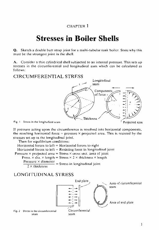
A. Co nside r a th in cylind rical shell subjected to an internal pressu re. Th is se ts upstresses in the circumfe re ntial and longitudinal axes which can be calcul ated asfollows:
CIRCUMFERENTIAL STRESS
Fig. I Stress in the lon gitudinal seam
Longitudinalseam --
If pressure acting upon the circumference is resolved into hor izontal compo ne nts.th e resulting horizontal force = pressure x project ed area. Th is is resisted by th estresses se tup in the longitudinal joint.
Th en for equilibrium conditions:Hori zontal forces to left = Horizontal forces to rightHor izontal forces to left = Resisting force in longitud inal joi nt
Pressure x projected area = Stress x cross sect. area of jointPr ess. x dia. x length = Stress x 2 x thickness x len gthPr essure x diameter S . . di I · ·--0------,:-:--0-- - - = tress 10 longitu ina j oint
2 x thickn ess
LONGITUDINAL STRESS
= :~"~d~..... ,--'-..... :-Po-,-;::==9
Fig.2 St ress in the circu mfere n tial Circumferen tia lseam seam
~ < , Area of circ umfe rential
Qseam
) Area of end plate_/
STRESSES IN BOI LER SHELLS
The force ac ting upon th e e nd pla te is resisted by th e stress se t up In t hecircu mfe ren tia l jo int.
Then for equil ibrium co nd itio ns :
Horizontal forces to left = Horizontal forces to rightPr essure x e nd plat e area = Resisting fo rce in circumfe re ntia l jo int
Press. x : x di am et er' = Stre ss x cross sect. a rea of jo in t
Pr essu re x di am eter
4 x thickn ess= Stress in circumfere ntia l jo int
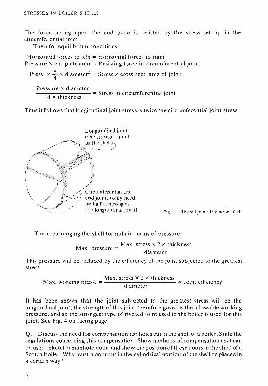
Thus it follow s th at longitudinal joint stre ss is tw ice th e circumfere ntial joi nt stress .
\\
\\
-,
Longitud inal joint(the strongest joint
~T'"~. in the she~
{~~~--l"" I~ I
/ l~~ircum fer e nt ia l and/ 1> /,/// end joints (only need, " / be half as strong as
'--.. . the longitudinal joint) Fig. 3 Rivel ed joi nts in a boile r she ll
T hen re arranging the shell fo rm ula in te rms o f pressu re
Max . stress x 2 x thi cknessMax. pressure = - --- -:-:------ -
di am eter
Thi s pres sure will be reduced by the efficiency o f the joint subjected to th e grea tes tstress .
Max. stress x 2 x th icknessMax . wo rking press. = . x Joi nt efficie ncy
d iam et er
It has been sho wn th at the joint subjected to the great est stress will be thelongit udinal jo int ; th e stre ngth of th is joi nt th er e fore gove rns the allowable wo rkingpressur e , and so the stronges t type of rive ted jo int used in th e boil e r is used for thisjoin t. See Fig. 4 on facing page .
Q. D iscuss th e need fo r co mpe nsa tion for holes cut in th e shell of a boi le r. State theregul at ions co nce rn ing th is compen sation . Show methods of com pe nsa tion th at canbe used. Sketch a manhole door, an d show the po sit ion of th ese doors in th e she ll o f aScotch boiler. Wh y mu st a door cut in th e cylind rica l portion of the she ll be placed ina certai n way?
2
ST RESS ES IN BO ILE R SH E LLS
Alternate rivets omitted fromEnd plate the outer rows '"'_,
~"""""_~) Outer strap)
Rivet on<i:. of the
joint
o
o
oo
Io
o
,/
o
o
Shellplate
o
o
o
o
o
o
" ); ' Outer strap
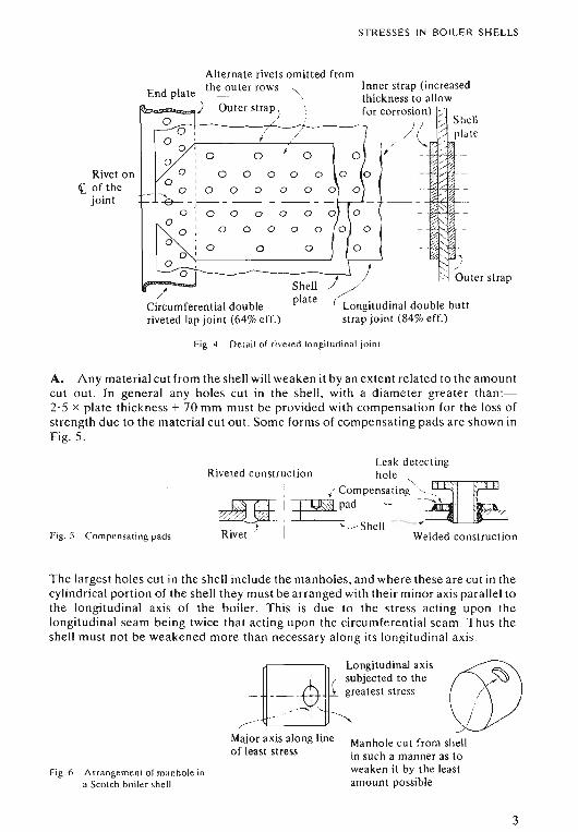
Fig. ~ Det ail of rive ted loogitudi nal jnin t
A. A ny mat er ial cut fro m the she ll will weaken it by an exte nt related to th e amo untcut out. In gen er al any holes cut in the shell, with a d iameter great e r tha n:2· 5 x plate thi ckn ess + 70 mm mu st be pr ovided with co m pe nsa tio n for th e loss ofstre ng th due to th e mat e rial cut ou t . So me forms of co mpensa ting pad s are shown inFig, 5,
Fig, 5 Co mpe nsa ting pad s
Leak detectingRiveted construction hole ">. " '
, { compen sa ting ,,_~__ - "~I~pad -- - -""\",,_~~ .
. ) I' '" "S hell " --- ~RIVet Welded construction
The larges t holes cut in th e she ll include th e manholes, and where these are cut in thecyli ndrica l portion of th e she ll they mu st be arr anged with th eir minor axis parall el toth e longitudinal ax is o f the boiler. T his is due to th e st ress acting up o n thelongitudinal seam be ing twice that ac ti ng up on the circumferent ial seam , Thus th eshe ll mu st not be weake ned more th an necessary alo ng its lo ngitu d inal ax is.
Manhole cut from shellin such a manner as toweaken it by the leastamount possible
Fig,6 A rra ngement of manhole ina Scotch bo iler she ll
~Longitud inal axis
, subjected to the___,':$: ~ greatest stress
- --...-:Major axis along lineof least st ress
3
STRESSES IN ROlLER SHELLS
Stud (screwedinto door) ./.-.0
Fig. 7 Manhole door
Q. Discuss the reasons for the limitation of pressure imposed upon tank typeboilers.
A. With reference to the thin shell formula :
Pressure x diameterStress = .
2 x plate thickness
oThickness
Fig. H
Thus it can be seen that if the stress in the material is to be keptwithin fixed limits (as is the case with boiler material) then, if thepressure or diameter increases, the plate thickness must alsochange if the ratio is to remain constant.
Therefore if boiler pressure is increased , either the boiler shelldiameter must decrease, or the boiler scantlings increase; the latter leading toincreased cost and weight. In order to accommodate the combustion chamber,smoke tubes, etc., no great reduction in the shell diameter of tank type boilers ispossible, and thus very thick shell plates would be required for high pressure .
The furnace must also be considered, as its thickness must be kept within certainlimits to prevent overheating. However, its diameter cannot be reduced too much,otherwise difficulties in burning the fuel in the furnace would arise .
For these reasons the maximum pressure in tank type boilers is limited to about1750 kNrrn".
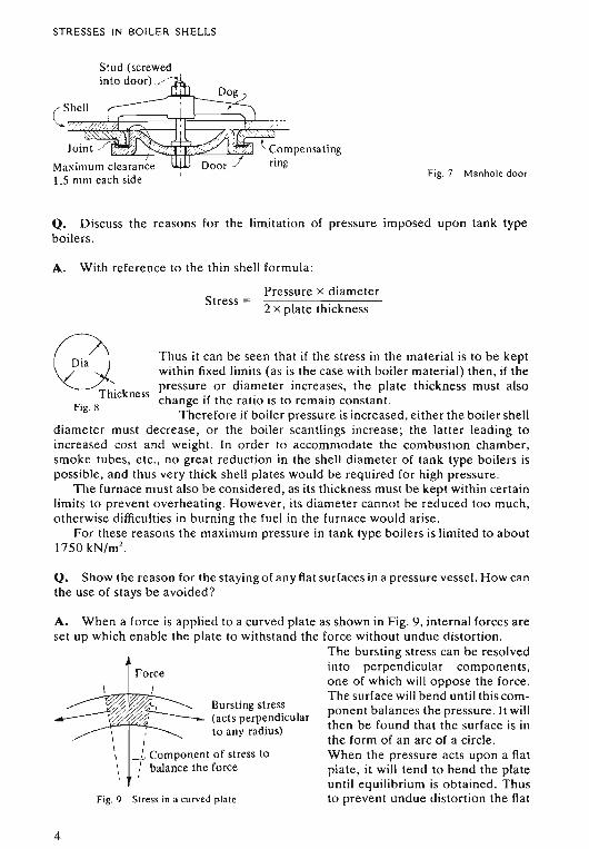
Q. Show the reason for the staying of any flat surfaces in a pressure vessel. How canthe use of stays be avoided?
Stress in a curved plate
I
-.1.. Component of stress to: balance the force
,\\\\\,
Fig. 9
\ tFo~ce~ Bursting stress~~ %:.--------- (acts perpendicular
--"~I"'"'"'i--..- to any radius)
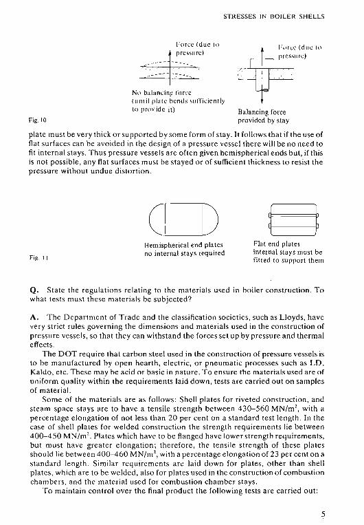
A. When a force is applied to a curved plate as shown in Fig. 9, internal forces areset up which enable the plate to withstand the force without undue distortion.
The bursting stress can be resolvedinto perpendicular components,one of which will oppose the force .The surface will bend until this component balances the pressure. It willthen be found that the surface is inthe form of an arc of a circle .When the pressure acts upon a flatplate, it will tend to bend the plateuntil equilibrium is obtained. Thusto prevent undue distortion the flat
4
STRESSES IN BOILER SHELLS
Fig. 10
l-orce (due 10pressure)
N" balancine force(u ntil plate bends su ff icie nt lyto provide it)
hlr,c (due 10
pr essure)
Balancingforceprovided by stay
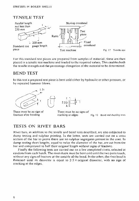
plate must be very thick or supported by some form of stay. It follows that if the use offlat surfaces can be avoided in the design of a pressure vessel there will be no need tofit internal stays. Thus pressure vessels are often given hemispherical ends but, if thisis not possible, any flat surfaces must be stayed or of sufficient thickness to resist thepressure without undue distortion.
Fig. II
o-'------!DHemisphericalend platesno internal stays required
Flat end platesinternal stays must befitted to support them
Q. State the regulations relating to the materials used in boiler construction. Towhat tests must these materials be subjected?
A. The Department of Trade and the classification societies, such as Lloyds, havevery strict rules governing the dimensions and materials used in the construction ofpressure vessels, so that they can withstand the forces set up by pressure and thermaleffects .
The DOT require that carbon steel used in the construction of pressure vessels isto be manufactured by open hearth, electric, or pneumatic processes such as LD.Kaldo, etc . These may be acid or basic in nature . To ensure the materials used are ofuniform quality within the requirements laid down. tests are carried out on samplesof material.
Some of the materials are as follows: Shell plates for riveted construction , andsteam space stays are to have a tensile strength between 430-560 MN/m 2
, with apercentage elongation of not less than 20 per cent on a standa rd test length. In thecase of shell plates for welded construction the strength requirements lie between400-450 MN/m 2
• Plates which have to be flanged have lower strength requirements.but must have greater elongation ; therefore, the tensile strength of these platesshould lie between 400-460 MN/mZ, with a percentage elongation of 23 per cent on astandard length. Similar requirements are laid down for plates, other than shellplates, which are to be welded, also for plates used in the construction of combustionchambers, and the material used for combustion chamber stays.
To maintain control over the final product the following tests are carried out:
5
STR ESSES IN BOILER SHELLS
TENSILE TESTParallel lengthnot less than ,.,._.- _
23~~
~-j -
~ 200 mmStandard test gauge lengthpiece
Moving crosshead.------------,, -~/
Rams /
Fixedcrosshead
Test machine Fig. 12 Tens ile test
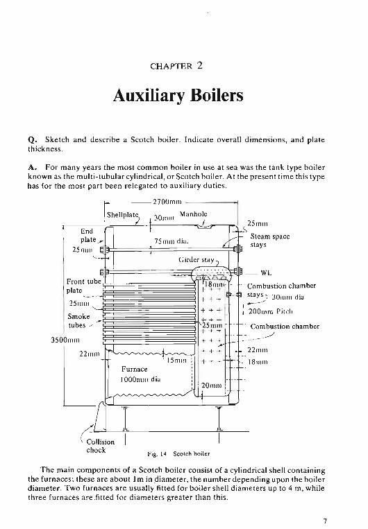
For th is standard te st pieces are pr ep ar ed from samples o f material ; these are thenplaced in a ten sile test ma ch ine and lo aded to the re quired va lues, This enables boththe ten sile strength an d the percentage elongation of the mat erial to be determined .
BEND TEST
In thi s test a pr epared test piece is bent cold eithe r b y hydraul ic or o the r pressure, orb y repeated hamm er blow s.
There must be no sign offracture after bending
T~'2 .5 ~ -i>l.i I
There must be no signs ofcracking at edges Fig. 13 Ben d and duct ility tests
TESTS ON RIVET BARSRivet ba rs, in add ition to the ten sile and bend tests described, are also subjecte d todu mp testing and sulphur pr int ing. In the latter, te sts are ca rried o ut on a cro ssse ctio n of the ba r to pr ove there are no sulphur segregates pr esent in the core . Ind ump testing sho rt lengths, eq ua l to twice th e diame te r o f the bar , are cut from thebar and co m pressed to half th e ir ori gin al len gth with out sign s o f fracture.
Fin ally the fo llowing tests are carried out o n a few co mple ted rivet s, selecte d atrandom from each batch. Th e rivet sha nk must be bent co ld until the two parts tou ch,with out any signs of fracture at the outside of th e bend . In th e othe r, th e rivet head isflattened until its diameter is eq ual to 2·5 x origina l d iame te r, with no sign ofcracking at the ed ges.
6
CHAPTER 2
Auxiliary Boilers
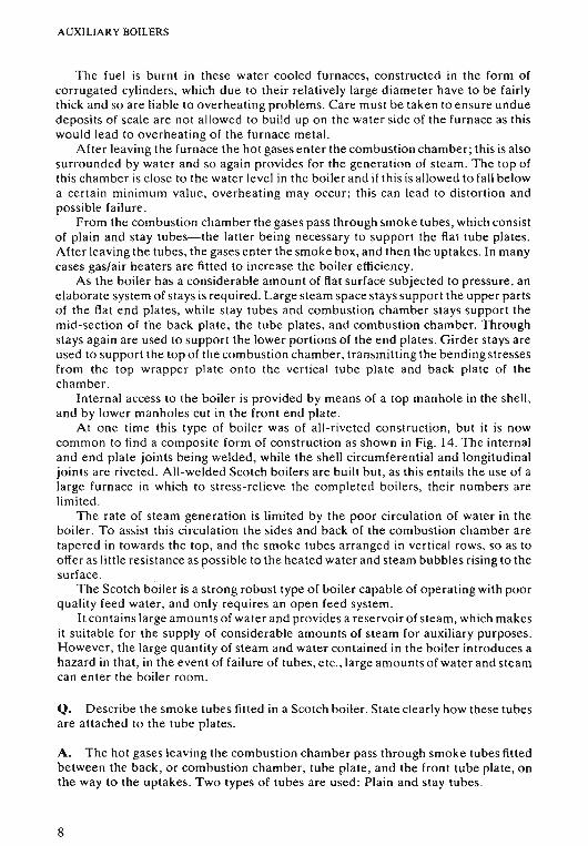
Q. Sketch and describe a Scotch boiler. Indicate overall dimensions, and platethickness.
A. For many years the most common boiler in use at sea was the tank type boilerknown as the multi-tubular cylindrical, or Scotch boiler. At the present time this typehas for the most part been relegated to auxiliary duties.
25 0111I
- - Combustion chamber- ..--/- .,.
- _ 22 111 111r--
I- 18111111_. ~ .
I
+- + -125 III 111
T -+ "T
c: irder stay ")
. -=-=--t:;cdi.;--~- ·-: --·tti ~- WL
r18111111 Combustion chamber+ + ++ + -t Il==l;j ~ 30111111 dia
+ -+ -I. r 200111111 Pit<:h- ..j
Fig. t 4 Scot ch bo ile r
t =
75111111 dia.
I
Furnace
1000111111 diu
~----270001I11 - - - - - --1
30 ManholeI 111111 I!~hellPlat~
221llnl-
25111111
Smoke -tubes /"
, 151111!l i t- -l-
i I" -L/~~,"",,~'J"'V--v"-""'./~ j ?Omlll i"
--;JJ~ I I
(Collision Ichock
l End I -plate »: V - Steam space
4E~===~=======~/~* stays
I25111111 !oJ I
" - 1-0-
§.
plate .... ._- _.
3500111111
The main components of a Scotch boiler consist of a cylindrical shell containingthe furnaces; these are about 1m in diameter, the number depending upon the boilerdiameter . Two furnaces are usually fitted for boiler shell diameters up to 4 m, whilethree furn aces are fitted for diameters greater than this .
7
AUXILIARY BOILERS
The fuel is burnt in these water cooled furnaces, constructed in the form ofcorrugated cylinders, which due to their relatively large diameter have to be fairlythick and so are liable to overheating problems. Care must be taken to ensure unduedeposits of scale are not allowed to build up on the water side of the furnace as thiswould lead to overheating of the furnace metal.
After leaving the furnace the hot gases enter the combustion chamber; this is alsosurrounded by water and so again provides for the generation of steam . The top ofthis chamber is close to the water level in the boiler and if this is allowed to fall belowa certain minimum value, overheating may occur; thi s can lead to distortion andpossible failure.
From the combustion chamber the gases pass through smoke tubes , which consistof plain and stay tubes-the latter being necessary to support the flat tube plates .After leaving the tubes, the gases enter the smoke box, and then the uptakes. In manycases gas/air heaters are fitted to increase the boiler efficiency.
As the boiler has a considerable amount of flat surface subjected to pressure, anelaborate system of stays is required . Large steam space stays support the upper partsof the flat end plates, while stay tubes and combustion chamber stays support themid-section of the back plate, the tube plates, and combustion chamber. Throughstays again are used to support the lower portions of the end plates. Girder stays areused to support the top of the combustion chamber, transmitting the bending stressesfrom the top wrapper plate onto the vertical tube plate and back plate of thechamber.
Internal access to the boiler is provided by means of a top manhole in the shell,and by lower manholes cut in the front end plate .
At one time this type of boiler was of all-riveted construction, but it is nowcommon to find a composite form of construction as shown in Fig. 14. The internaland end plate joints being welded, while the shell circumferential and longitudinaljoints are riveted . All-welded Scotch boilers are built but, as this entails the use of alarge furnace in which to stress-relieve the completed boilers, their numbers arelimited .
The rate of steam generation is limited by the poor circulation of water in theboiler. To assist this circulation the sides and back of the combustion chamber aretapered in towards the top, and the smoke tubes arranged in vertical rows, so as tooffer as little resistance as possible to the heated water and steam bubbles rising to thesurface .
The Scotch boiler is a strong robust type of boiler capable of operating with poorquality feed water, and only requires an open feed system.
It contains large amounts of water and provides a reservoir of steam, which makesit suitable for the supply of considerable amounts of steam for auxiliary purposes.However, the large quantity of steam and water contained in the boiler introduces ahazard in that, in the event of failure of tubes, etc., large amounts of water and steamcan enter the boiler room .
Q. Describe the smoke tubes fitted in a Scotch boiler. State clearly how these tubesare attached to the tube plates.
A. The hot gases leaving the combustion chamber pass through smoke tubes fittedbetween the back, or combustion chamber, tube plate, and the front tube plate, onthe way to the uptakes. Two types of tubes are used : Plain and stay tubes .
8
AUXILIARY BOILERS
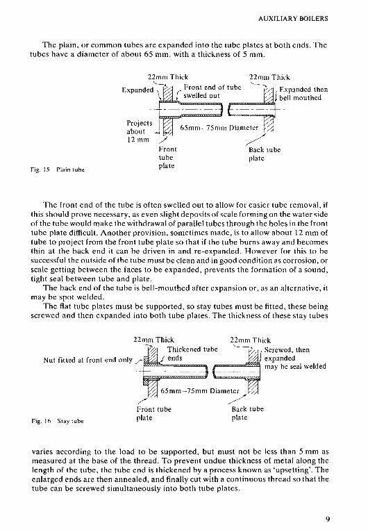
The plain, or common tubes are expanded into the tube plates at both ends. Thetubes have a diameter of about 65 mm. with a thickness of 5 mm.
22mm Thick'------.".
( Expanded then) bell mouthed
fF===..l>:6i1si
65mm-75mm Diameter
/, Back tubeplate
Projects I
about --il2mm /
Fronttubeplate
22mm Thick~Expanded Front end of tube\ ( swelled out
Fig. 15 Plain tube
The front end of the tube is often swelled out to allow for easier tube removal, ifthis should prove necessary, as even slight deposits of scale forming on the water sideof the tube would make the withdrawal of parallel tubes through the holes in the fronttube plate difficult. Another provision, sometimes made, is to allow about 12 mm oftube to project from the front tube plate so that if the tube burns away and becomesthin at the back end it can be driven in and re-expanded. However for this to besuccessful the outside of the tube must be clean and in good condition as corrosion, orscale getting between the faces to be expanded, prevents the formation of a sound,tight seal between tube and plate.
The back end of the tube is bell-mouthed after expansion or, as an alternative, itmay be spot welded.
The flat tube plates must be supported, so stay tubes must be fitted, these beingscrewed and then expanded into both tube plates. The thickness of these stay tubes
/'Front tubeplate
22mm Thick 22mm Thick--... Thickened tUb~'---~ Screwed, then
Nut fitted at front end only r: J ends expanded___ _ _ _ _ may be seal welded
65mm-75mm Diameter//Back tubeplateFig. 10 Stay tube
varies according to the load to be supported, but must not be less than 5 mm asmeasured at the base of the thread. To prevent undue thickness of metal along thelength of the tube, the tube end is thickened by a process known as 'upsetting'. Theenlarged ends are then annealed, and finally cut with a continuous thread so that thetube can be screwed simultaneously into both tube plates.
9
AUXILIARY BOILERS
After the tube has been screwed and then expanded into the tube plates, nuts areusuaily fitted at the front end, but not in the combustion chamber as this would tendto cause overheating due to excess metal thickness . In some cases seal welding maybe used instead , but it should be noted that seal welding must only be carried out onsound, screwed and expanded tubes and not in an attempt to repair a corroded or thintube end .
As an alternative to screwing the stay tubes into the tube plates, welding can beused. This strength weld can be carried out after the boiler has been stress relieved, ifthis is necessary, without further heat treatment, provided the tubes are not adjacentwithin the same tube nest. However, the tubes must still be expanded before andafter welding.
The proportion of stay tubes to plain tubes will be in the order of 1: 3.In some cases the marginal stay tubes in the tube nest are made slightly thicker to
allow for the greater stresses to which they are subjected .
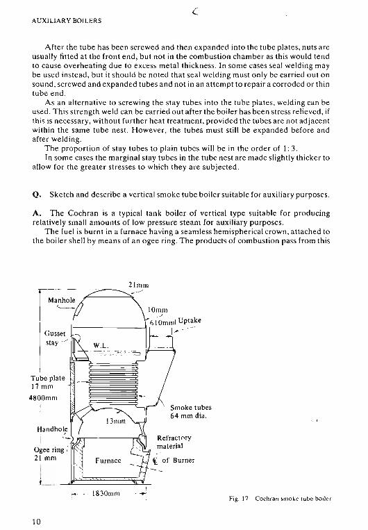
Q. Sketch and describe a vertical smoke tube boiler suitable for auxiliary purposes.
A. The Cochran is a typical tank boiler of vertical type suitable for producingrelatively small amounts of low pressure steam for auxiliary purposes.
The fuel is burnt in a furnace having a seamless hemispherical crown, attached tothe boiler shell by means of an ogee ring. The products of combustion pass from this
Smoke tubes64 mm dia.
Refractorymaterial
21mlll.../
Gussetstay J
Handhol;
Ogee ring i21 mm
iIIL __...
Tube plate ~~Iiir17mm
4800mm
I183011101 --- Fig . 17 Cochran smoke tube boiler
10
L AUXILIARY BOILERS
furnace into a combustion chamber lined with refractory material, and then throughsmoke tubes into the smoke box at the front of the boiler.
The cylindrical boiler shell with its hemispherical crown, together with thehemispherical furnace forming the bottom of the pressure space, requires no stays.However the combustion chamber top requires support, and this is provided bymeans of a gusset stay which transfers the stresses from the flat top of the chamberonto the boiler shell. The flat tube plates are tied together by means of stay tubesscrewed into them.
A modified form of this boiler is now produced in an all-welded form.As all the heating surfaces are below the water level, and the straight, relatively
short smoke tubes are readily accessible for cleaning or renewal, this type of boilerforms a robust unit suitable for use with an open feed system and poor quality feedwater.
The boiler can be operated with either solid or liquid fuels, although in sea-goingvessels oil firing is invariably used.
The Cochran boiler can also be adapted for use as an exhaust gas boiler, using theexhaust gases from an internal combustion engine for the generation of steam. Inother cases boilers designed for composite firing, using exhaust gases and/or oilfiring, are fitted .
Refractory material is fitted in the combustion chamber, and on the floor andsides of the furnace . Special care should be taken in the latter case to ensure that therefractory is high enough to prevent direct radiant heat coming onto the ogee ring,and lower parts of the hemispherical furnace crown. These lie at the bottom of anarrow water space into which suspended soiids from the boiler water tend to settleout, and then form scale on heated surfaces , thus leading to the overheating andsubsequent distortion of the ogee ring.
Internal access to the boiler is provided by a manhole in the top of the shell , whilehand holes in the lower section of the shell provide access to the lower parts of thewater space for cleaning and inspection .
Hinged smoke box doors give access to the tubes and tube plate at the front, whilea removable rear panel fitted to the combustion chamber gives access to the backtube plate .
Q. Compare a welded type auxiliary boiler with a design using riveted construction.
A. At one time welding was not considered suitable for the manufacture of pressurevessels, but with modern welding and test procedures it has entirely replaced riveting inthe design of contemporary boilers.
The use of welded joints avoids many problems associated with riveted joints, suchas leakage, caustic embrittlement with resultant cracking between rivet holes, etc . Inaddition, as there is no longer the need to overlap plates in forming seams , there is anoverall reduction in boiler weight ; also, problems of overheating where the overlapsoccurred on heated surfaces are avoided.
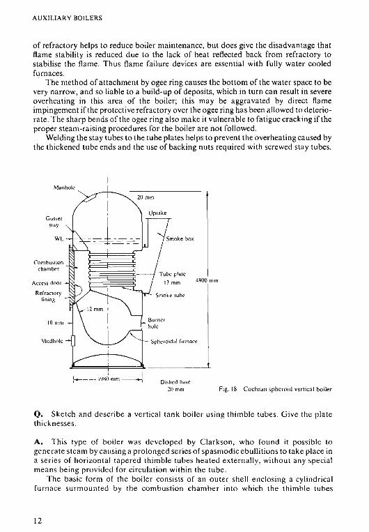
Fig. 17 shows a riveted boiler with a hemispherical furnace attached to the boilershell by means of the ogee ring connection necessary with riveted construction. Thishas been replaced in the welded design shown in Fig. 18 by a water cooled furnace ofspheroidal shape. This, apart from the burner quarl , needs no protective refractorymaterial, which in turn allows the fully water cooled furnace to provide a greaterradiant heat surface with a resultant increase in steam generation. The smaller amount
II
AUXILIARY BOILERS
of refractory helps to reduce boiler maintenance, but does give the disadvantage thatflame stability is reduced due to the lack of heat reflected back from refractory tostabilise the flame. Thus flame failure devices are essential with fully water cooledfurnaces .
The method of attachment by ogee ring causes the bottom of the water space to bevery narrow, and so liable to a build-up of deposits, which in turn can result in severeoverheating in this area of the boiler; this may be aggravated by direct flameimpingement if the protective refra ctory over the ogee ring has been allowed to deteriorate . The sharp bends of the ogee ring also make it vulnerable to fatigue cracking if theproper steam-raising procedures for the boiler are not followed.
Welding the stay tubes to the tube plates helps to prevent the overheating caused bythe thickened tub e ends and the use of backing nuts required with screwed stay tubes .
Manhole
Gussetstay
WL
Combustio nchamber
Access door
Refractorylining
10 mm
Mudhole
4900 mm
Burnerhole
Spheroidal furnace
Di:o.hed base20 mm Fig . 18 Cochran spheroid vertical boiler
Q. Sketch and describe a vertical tank boiler using thimble tubes. Give the platethicknesses.
A. Thi s type of boiler was devel oped by Clarkson, who found it possible togenerate steam by causing a prolonged series of spasmodic ebullitions to take place ina series of horizontal tapered thimble tubes heated externally, without any specialmeans being provided for circulation within the tube .
The basic form of the boiler consists of an outer shell enclosing a cylindricalfurnace sur mounted by the combustion chamber into which the thimble tubes
12
AUXILIARY BOILERS
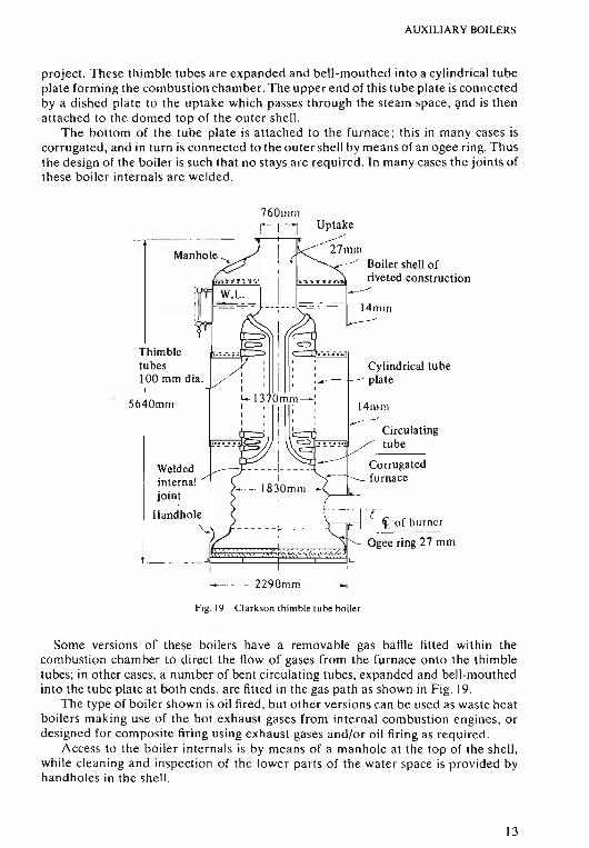
project. These thimble tubes are expanded and bell-mouthed into a cylindrical tubeplate forming the combustion chamber. The upper end of this tube plate is connectedby a dished plate to the uptake which passes through the steam space, and is thenattached to the domed top of the outer shell.
The bottom of the tube plate is attached to the furnace; this in many cases iscorrugated, and in turn is connected to the outer shell by means of an agee ring . Thusthe design of the boiler is such that no stays are required. In many cases the joints ofthese boiler internals are welded.
Corrugatedfurnace
·C~ of burner
---- - ------Ogee ring 27 mm
Circulatingtube
I4III III
Uptake»>
270110_/ Boiler shell of
riveted construction..----'
14mm
Cylindrical tube.__-l----" plate
760lllm
i l l
------~------
_ ... _ J~~~LI I
Weldedinternaljoint
Handhole~
Thimbletubes100 mm dia. /
5640mlll
4-~- - - 22901010 . .~
Fig.19 Clarkson thimble tube boiler
Some versions of these boilers have a removable gas baffle fitted within thecombustion chamber to direct the flow of gases from the furnace onto the thimbletubes; in other cases, a number of bent circulating tubes, expanded and bell-mouthedinto the tube plate at both ends, are fitted in the gas path as shown in Fig . 19.
The type of boiler shown is oil fired, but other versions can be used as waste heatboilers making use of the hot exhaust gases from internal combustion engines, ordesigned for composite firing using exhaust gases and/or oil firing as required.
Access to the boiler internals is by means of a manhole at the top of the shell,while cleaning and inspection of the lower parts of the water space is provided byhandholes in the shell.
13
AUXILIARY BOILERS
These boilers will operate for long periods without internal cleaning although, ifan undue amount of scale forms inside the thimble tubes, it is very difficult to remove .Thus reasonable quality feed water should be provided. The formation of scale willsubject the thimble tubes to a certain amount of overheating, but the fact that theyare attached at one end only greatly reduces the possibility of tube failure.
The gas side must be kept clean as even thin deposits of soot can cause a drasticreduction in the amount of heat conducted. It is claimed that oily deposits can beburnt off the outside of the thimble tubes when the boiler is dry without damage, butthis procedure must not be carried out if circulating tubes attached at both ends arefitted .
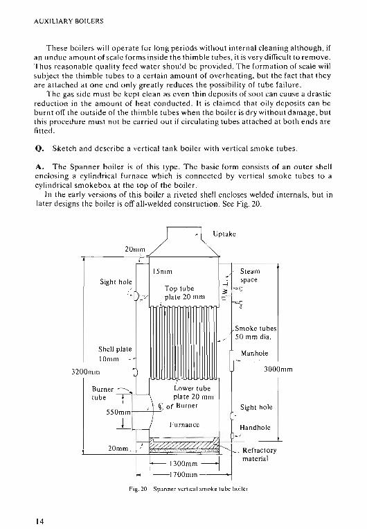
Q. Sketch and describe a vertical tank boiler with vertical smoke tubes .
A. The Spanner boiler is of this type. The basic form consists of an outer shellenclosing a cylindrical furnace which is connected by vertical smoke tubes to acylindrical smokebox at the top of the boiler.
In the early versions of this boiler a riveted shell encloses welded internals, but inlater designs the boiler is off all-welded construction. See Fig. 20.
~"k'2UIlllll
~
15mm Steam~
Sight hole -lspace
/ Top tube!~
-<>q{ - plate 20 mm
r-- -<L~I
Smoke tubes
~/ 50 mm dia.
Shell plateManhole
tOmm - - ./
32OOnlin ~ 3000111m
I
Burner .::::::3 Lower tubetube T '------' pia te 20 mm
{ i. of Burner Sight hole550mm .
_!I Furnancc Handhole-~
20mm . ! V///-0/'//////'~._ Refractory
I f.-- 1300mm -----j material
~--1700mm_.
Fig.20 Spanner vertical smoke lube boiler
14
AUXILIARY BOILERS
The vertical smoke tubes are a patent design known as swirlyflow tubes; theyhave a special twist along the greater part of their length, only a short portion at eachend being left plain to allow for expansion. It is claimed that these tubes are moreefficient than normal plain smoke tubes in that they cause the gases passing throughto swirl , so coming into more intimate contact with the tube wall and thereforeincreasing the rate of heat transfer.
No stays are required for the outer shell and for the internals. Only the flat tubeplates need to be supported ; this is done by stay tubes, of plain section, expanded andthen welded into the tube plates.
Internal access is obtained by means of a manhole in the outer shell , and byhandholes and sightholes cut at strategic positions in the she ll to allow for cleaningand inspection .
The boiler shown in Fig. 19 is oil fired, the fuel being burnt in the water cooledfurnace-only the floor of which is covered by refractory material. The gases leavingthe furnace pass to the smokebox via the vertical smoke tubes.
In addition to the oil fired version shown, two others are available suitable for usein waste heat recovery systems as fitted in motor vessels . Both of these have the sameform of vertical tube stack, which in the exhaust gas version is circulated by theengine exhaust gases , while in the composite version a baffle separates the exhaustgas section of the tube stack from the oil fired flue gas section. These two gas streamsare isolated from each other, each leaving by its own uptake, thus allowing oil firingto be used in conjunction with the exhaust gases from the engine.
Q. Sketch and describe a vertical water tube boiler suitable for auxiliary purposes.
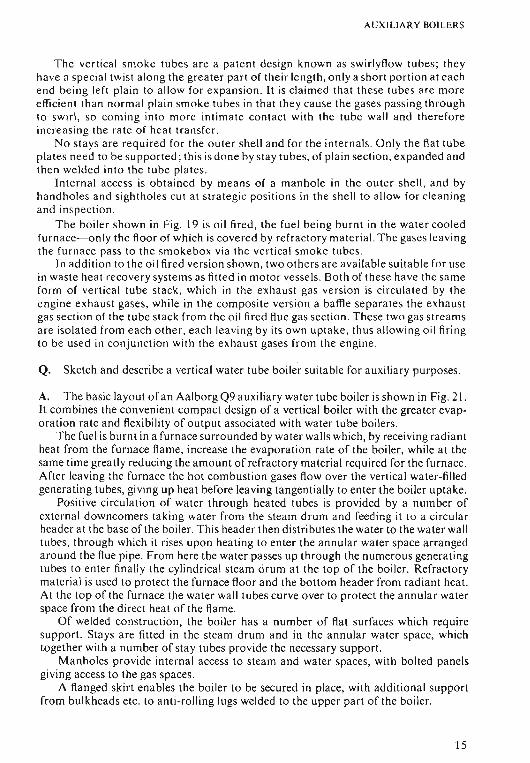
A. The basic layout of an Aalborg Q9 auxiliary water tube boiler is shown in Fig. 21.It combines the convenient compact design of a vertical boiler with the greater evaporation rate and flexibility of output associated with water tube boilers.
The fuel is burnt in a furnace surrounded by water walls which, by receiving radiantheat from the furnace flame, increase the evaporation rate of the boiler, while at thesame time greatly reducing the amount of refractory material required for the furnace.After leaving the furnace the hot combustion gases flow over the vertical water-filledgenerating tubes, giving up heat before leaving tangentially to enter the boiler uptake.
Positive circulation of water through heated tubes is provided by a number ofexternal downcomers taking water from the steam drum and feeding it to a circularheader at the base of the boiler. This header then distributes the water to the water walltube s, through which it rises upon heating to enter the annular water space arrangedaround the flue pipe. From here the water passes up through the numerous generatingtubes to enter finally the cylindrical steam drum at the top of the boiler. Refractorymaterial is used to protect the furnace floor and the bottom header from radiant heat.At the top of the furnace the water wall tubes curve over to protect the annular waterspace from the direct heat of the flame .
Of welded construction, the boiler has a number of flat surfaces which requiresupport. Stays are fitted in the steam drum and in the annular water space, whichtogether with a number of stay tubes provide the necessary support.
Manholes provide internal access to steam and water spaces, with bolted panelsgiving access to the gas spaces.
A flanged skirt enables the boiler to be secured in place, with additional supportfrom bulkheads etc . to anti-rolling lugs welded to the upper part of the boiler.
15
AUXILIARY BOILERS
Uptake
Smoke bOKAnn ula r Winerspare
Furnace .-
Burner position
Slays
Cylindrical steam space
W.L.
Generating tu bes
Down come r
Flue pipe
Water wall tu be 'S
Refr actory materi al
1~~~~~~~~~~ Circular bottomheader Fig. 21 Aa lbor g vertical wa ter lube boiler
In many cases the steam drum also acts as a steam receiver for an exhaust gas boiler.A modified version of this boiler can be used to incine rat e waste oil, sol id waste and
sewage, using the resulting heat to gene rat e steam.
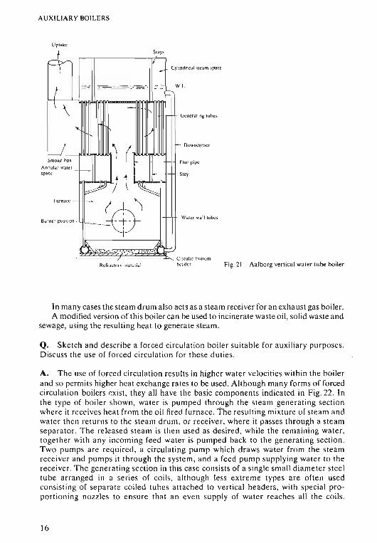
Q. Sketch and de scrib e a forc ed circulatio n boil er suita ble for au xiliar y pu rposes.D iscuss the use of fo rced circulation for the se duties.
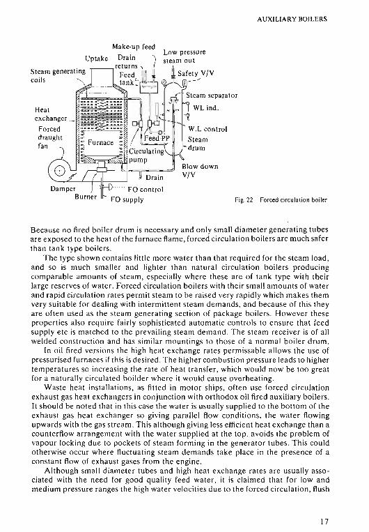
A. Th e use of forc ed circulation result s in higher wat er velocities within the boilerand so permits higher heat exchange rates to be used. Although many forms of forcedcirculation boilers exist, they all have the basic components indicated in Fig. 22. Inthe type of boiler shown, water is pu mped through the stea m generating sectio nwhere it receives heat fro m the oi l fired furn ace. Th e resulting mixture of stea m andwater then returns to the steam drum. or receive r, where it passes thr ou gh a stea mse parator. The re leased stea m is then used as desired, while the remaining water,toge ther with an y incoming feed water is pumped back to the generating sect ion.Tw o pumps are requ ired, a circulating pump which dr aws water from the stea mreceiver and pumps it through the syste m, and a feed pump supplying water to thereceiver. The generatin g se ction in thi s case consists of a single small diameter stee ltub e arra nged in a se ries of coils. altho ugh less extreme types ar e ofte n usedcon sisting of separate coile d tub es attached to vertical header s, with special proport ioning nozzles to en sur e that an eve n supply of wa te r reaches all the coils.
16
AUXILIARY BOILERS
Fig. 22 Forced circulation boiler
Make-up feedLow pressure
Drain '\ steam outreturns -, I t
Feed IIIU ~ Safety V!V
t,"k:1~rlii" .; "'''''0<
~;:~:::er-I~I~~r/~ I~l WWLL~:;ml1:~Ught F~~~~P Steam
Circulating drum~~::';~]pump
~~v=o~~..J Blow downT Orain V{V
Uptake
Steam generating
coils '"
Because no fired boiler drum is necessary and only small diameter generating tubesare exposed to the heat of the furnace flame, forced circulation boilers are much saferthan tank type boilers.
The type shown contains little more water than that required for the steam load,and so is much smaller and lighter than natural circulation boilers producingcomparable amounts of steam, especially where these are of tank type with theirlarge reserves of water. Forced circulation boilers with their small amounts of waterand rapid circulation rates permit steam to be raised very rapidly which makes themvery suitable for dealing with intermittent steam demands, and because of this theyare often used as the steam generating section of package boilers. However theseproperties also require fairly sophisticated automatic controls to ensure that feedsupply etc is matched to the prevailing steam demand. The steam receiver is of allwelded construction and has similar mountings to those of a normal boiler drum.
In oil fired vers ions the high heat exchange rates permissable allows the use ofpressurised furnaces if this is desired . The higher combustion pressure leads to highertemperatures so increasing the rate of heat transfer, which would now be too greatfor a naturally circulated boilder where it would cause overheating.
Waste heat installations, as fitted in motor ships, often use forced circulationexhaust gas heat exchangers in conjunction with orthodox oil fired auxiliary boilers.It should be noted that in this case the water is usually supplied to the bottom of theexhaust gas heat exchanger so giving parallel flow conditions, the water flowingupwards with the gas stream. This although giving less efficient heat exchange than acounterflow arrangement with the water supplied at the top, avoids the problem ofvapour locking due to pockets of steam forming in the generator tubes. This couldotherwise occur where fluctuating steam demands take place in the presence of aconstant flow of exhaust gases from the engine.
Although small diameter tubes and high heat exchange rates are usually associated with the need for good quality feed water, it is claimed that for low andmedium pressure ranges the high water velocities due to the forced circulation, flush
17
AUXILIARY BOILERS
any precipitated particles clear of generating tubes and allow them to collect assludge in headers etc from whence th ey can be blown out.
Q. State wh at is meant by the term package boil er. Sketch and describe a boiler ofthi s type.
A. Where rel ati vel y sm all , intermittant steam demands are to be met, use is oftenmade of package boilers. This term is usually applied to self contained units mountedo n a single bed plate and comprising a steam generating section , feed water syste mand pump, fuel oil system and pump, together with a forced draught fan . In additionsu itable control equipment will also be required . This package now only needsconnections to the ship's e lec trica l supply and other necessary se rvices to becomeope ra t ional.
Smoke tubesAir inlet ")
Frontchamber
Fig. 23 Typical pack age bo iler
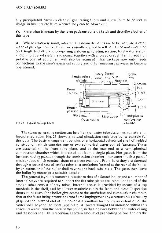
The steam gene rating secti on ca n be of tank or water tube design , using natural orforced circu la tio n. Fig. 23 shows a natural circula tion tank type boiler suitable forthi s duty. The ba sic a rrangeme nt consists of a horizont al cylindri cal she ll of weldedconstruction, wh ich contains o ne or two cylind rica l wat er cooled furnaces. Th eseare att ached to the front tube plate, and at the re ar e nd to a hemisphericalcombustion chamber which is pressed out from a singl e plate. Hot gases from th efurn ace , having passed through th e combust ion chamber, then enter th e first pa ss ofsm ok e tubes which co nd uc t them to a front chambe r. From here they are directedthrough a second pa ss of smoke tubes to a smo kebox form ed at the rear of the boilerby an extension of th e boiler shell beyond the back tube plate . The gases then leavethe bo iler by means of a suitable uptake .
The general layout is somewhat similar to that of a Scotch boiler and a number ofinternal stays are required to su pp ort the flat tube plates e tc. About o ne third of thesmoke tubes consist of stay tubes. Internal access is provided by me an s of a topmanhole in the shell , a nd by a lower manhole cut in the front end plate . Inspectiondoors a t the rear of the boiler give access to the smo ke box a nd co mbustio n chamber,that o f the latter being protected from flame impingement by a removabl e refractorypi .rg. At the forw ard e nd of the boiler is a wind box form ed by an ext en sion of theI .oiler she ll beyond th e front tube plate. A forced draught fan mounted within thisspace dr aws air from th e back of th e boiler, so th at it passes between the o ute r casingand the bo iler shell, thus receiving a certain amo unt of preheat ing befor e it e nte rs th e
18
AUXILIARY BOILERS
furn ace . A control damper is used to regulate this air flow . Th e usu al boilermountin gs are fitted.
Autom atic controls are provided to regul ate the fuel and air supplies in responseto cha nges in s team demand , whil e at th e sa me time maintaining the bo ile r waterlevel within th e desired limits . Once sta rted up the boiler will continue to operateaut om at ically, flashing up and shutti ng down to satisfy the steam requirem ents. Thecontrols are programmed to give a co rre ct se que nce for the different operatio ns to beca rried o ut sa fe ly. Vario us safety devices are fitted which will automatica lly shut theboiler down in the event of loss o f water, co m bustion air pre ssure , o r flam e Failure . Anumber of other devices ca n also be fitted to give wa rn ing, and if desired shut thebo iler down in the event of high stea m pressure o r wat e r level , low fuel o il o r upt aketemperatures etc. When o ne of th ese auto matic safety cut-o uts has o pe ra te d to shutthe boiler down, the device mu st be manually reset before the boiler can be returnedto se rvice after the fault has been rectified .
Although packaging gre atly simplifies the specifications required when orderingnew tonnage, the advantages to the o pe ra to r may be limited by th e lack of access tobe found with some of th ese pack age unit s.
A wide range of package bo ilers ar e available, with designs to cover steampress ures from 350 kN/m 2 to 2000 kN /m 2 and with evapo ra tio n rat es of up to10000 kg/hr.
Q. Sketch and describe a stea m to stea m generato r. Stat e the purpose of fitting sucha unit.
A. These can be used in co nj unction with high er pressure wa te r tube bo ilers toprovide low pressure sa turate d ste am for auxiliary purposes. High pre ssure stea mfrom the water tube boiler is supplied to heating coil s placed be low the water level inthe steam to steam gen er at or and so producing low press ure ste am in the generatorshe ll. The steam to stea m ge ne ra to r has its own se pa ra te feed water system, soprot ecting the feed syste m of th e high pressure boiler aga inst contamination byae rated and possibl y dirt y aux iliary drain returns. Thi s is es pecia lly important wherestea m heating is used in ca rgo tanks o r oil fuel heat er s, with th e eve r present risk ofthe return dr ain s being co nta mina ted with oil From leaki ng heatin g co ils. IFoil sho uldenter the steam to steam gen erat or it wo uld only cau se a reduction in the evap or ationrate due to foul ing of the heat ing coi ls, and wo uld not lead to tube failure as co uldhappen if the o il e nters a d irectl y fired bo ile r. Ho weve r the cos t of thi s a rra nge me nt isgreater than by supp lying th e low pressure stea m from the high pre ssure bo iler viapressure reducing va lves , a nd if necessary a desuperheater . Thus a stea m to stea mgenerator would only be fitted if the risk of o il co nta mina tion is con sid er ed tooutweight this higher initi al cost.
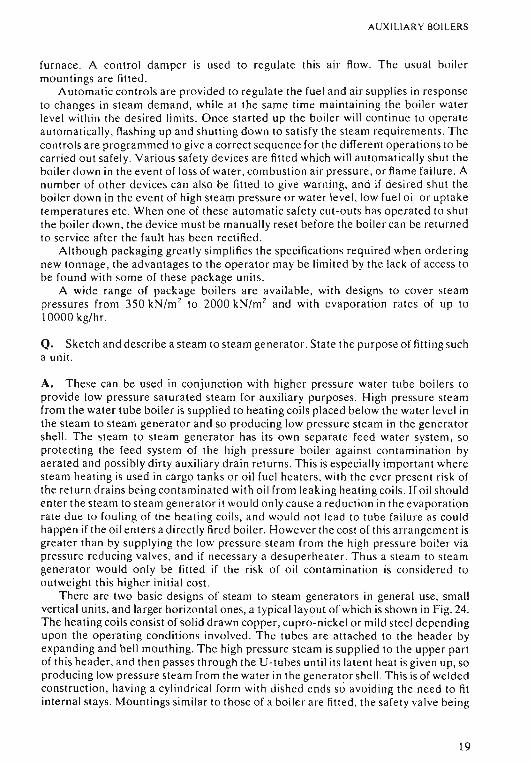
There are two basic designs of steam to steam generat ors in general use, sma llvertical units, and lar ger horizontal ones, a typical layout of which is shown in Fig . 24.The heating coil s co nsist of so lid drawn copper, cupro-nickel or mild steel dependingupon the o pe ra ting co nd itions involved. Th e tu bes are attached to the header byex pa nding a nd bell mouthing. The high pressure steam is supplied to the upper partof th is head er, a nd the n passes thro ugh the U -tubes unt il its lat ent heat is give n up , soproducing low pressure steam from the water in the ge nera to r she ll. This is of weldedconstruction , having a cylindrica l form with d ish ed e nds so avoiding the need to fitinternal stays. Mount ings similar to th ose of a boiler are fitted , the sa fe ty va lve bei ng
19
AUXILIARY BOILERS
---Header
/---=r---, ,--+---=->,--J Tube Dra inplate
r-~;;E~~~~Feed in
Shell
Steam drypipe Low pressure
steam out Safety V/V-~ y
Fig.24 Steam to steam generator .
able to jiandle.either the nor-val maximum evaporation, or that produced by thefailure of a heating tube. Internal access is provided by a manhole in the top of theshell, and provision is made for the complete removal of the tube stack. The typeshown has an evaporation rate of 12000 kg/hr at a pressure of 1000 kN/m 2 when theheating coils are supplied with 15000 kg/hr of saturated steam at a pressure of2100 kN/m 2
•
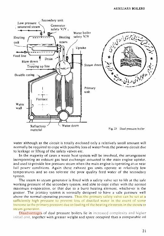
Q. Sketch and describe a dual pressure boiler capable of supplying low pressuresteam for auxiliary purposes .
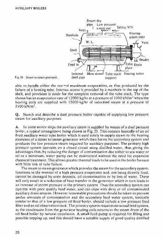
A. In some motor ships the auxiliary steam is supplied by means of a dual pressureboiler, a typical arrangement being shown in Fig, 25. This consists basically of an oilfired auxiliary water tube boiler which is used solely to supply steam to the heatingelements of a steam to' steam generator which then forms the secondary system andproduces the low pressure steam required for auxiliary purposes. The primary highpressure system operates on a closed circuit using distilled water, thus giving theadvantages that, by reducing the danger of contamination due either to sea water oroil to a minimum, water purity can be maintained without the need for expensivechemical treatment. This allows greater thermal loads to be used in the boiler furnacewith little risk of tube failure .
The steam to steam generator which pr ovides the steam for the secondary system ,functions in the manner of a high pressure evaporator and, not being directly fired ,cannot be damaged by scale deposits, oil contamination or by loss of water. Thesewill only result in a reduction of heat transfer in the generator which in turn leads toan increase of steam pressure in the primary system . Thus the secondary system canoperate with poor quality feed water, and can cope with dirty or oil contaminatedauxiliary drain returns. However reasonable precautions should be taken to preventundue amounts of contamination and the secondary feed water system, basicallysimilar to that of a low pressure oil fired boiler, should include a low pressure feedfilter and an oil observation tank . The primary system requires no actual feed system,as the condensate from the generator heating coils returns to the steam drum of theoil fired boiler by natural circulation. A small feed pump is required for filling andpossible topping up, and this should have a suitable supply of good quality distilled
20
AUXILIARY BOILERS
*.~:
*e. /f~\'"~~-iJ}/,Jl~~/
. ' _. ~ .,.
Fig . 25 Dual pressure boiler
Primaryunit
Steam drum
Waterwall
.Secondary unitLow pressure ~ .
: saturated steam Generator, safet y VIV .
Water boilerHeating safety V!V
=----I:~~~~~;:;;;~r.~~tc;-1" "!i'P"k.
/
Heat ing
coil
Feed line
wat er a ltho ug h as th e circ ui t is tot all y e nclosed o nly a relativel y sma ll am ount willnormall y be required to co pe with possible loss.of wa te r from the pr imary circuit du eto le ak age or lifting of th e safe ty valves e tc.
In th e majority of cas es a waste he at syste m will be involved . th e arr ange me ntincorporati ng an exhau st gas heat exchange r mounted in the main engi ne upt ake .and used to pr ovide low pressure steam whe n the ma in e ng ine is o pera ting at o r ne arfull powe r co ndi tio ns . Agai n th ese ex ha ust gas un its o pe ra te at relatively lowtemper atu res and so ca n tolerate th e po or quality fee d water of the secondarysyste m .
The stea m to steam ge nerato r is fitt ed with a safet y va lve se t to lift a t th e sa feworking pressure of th e seco nd ary sys te m. and able to co pe ei ther wit h the no rm almaximum evapora tion. or th at du e to a burst heat ing e leme nt. wh icheve r is th egrea te r . The primary sys te m is normall y designed to have a sa fe pr essure wellabo ve th e normal oper at ing pressure . T hus the prim ar y sa fe ty valv e ca n be set at asufficientl y high pressure to prevent loss of distilled wat er in th e eve nt of so meincrease in th e primary pressure due to fouling of the he at ing e le me nts in th e ste am to
ste am gen erat or.Disad vantages o f dual pr essure boi lers lie in increased complexit y and higher
initi al cos t. together with grea te r weight an d spa ce occ upie d than a co mpa rah le oil
21
AUXILIARY BOIL ERS{
fire d auxili ary boil e r of orthodox design . A nothe r problem ca n so me times arise fromove rco nfide nce in th e int eg rity o f the closed primary circui t, where cases ofco nta mi na tio n have occ urred, which th en re maining undetected have led to eventualtube Failure in th e water tube boiler forming the high pressure unit.
Q. Discuss the use of was te heat bo ile rs in mot or ships .
A. To incre ase th e ove ra ll th ermal efficiency of the plant as much use as po ssiblesho uld be made of th e heat in th e exhaust gases , which in th e case of an int e rn alco m bustion e ngine will be so me 30% of th e e ne rgy released du rin g th e combust ionprocess . In mot or ships the fitt ing of waste heat boil er s enables so me 20 % to 60 % ofth is heat in the main engine ex ha ust gases to be recovered and used to ge ne ra testea m. Th e ac tual per centage recovered de pe nds up on th e co mpl exity o f the was tehe at sys te m, and obviously so me use mu st be found For the stea m produced. This canran ge from simple heating pro cesses such as Fuel oi l heating, o r domesti c hot wat erand other-services, to its use in more complex stea m d riven plant. Here agai n is a widescope, ranging From pumps to stea m turb ine dr iven a lte rn ato rs. However th e morecomplex th is stea m plant the grea te r will be its init ial cos t, an d th e more so phistica tedsys te ms will normall y on ly be justified in ships spending at least two th irds of th ei rtim e at sea at design se rvice pow er. The output of th e waste heat rec o very systemsho uld be sufficie n: to handl e th e norm al stea m requirem ents a t sea . If addi tiona lsteam from oil fired boi le rs wo uld be fre q ue ntly required to su pple me nt the ste amproduced by th e waste heat boile r. then th e fitting of a comple x waste he at recover ysystem to produce steam will not normall y be ju stifi ed .
A no the r adva ntage ga ine d from th e fitt ing o f was te heat boi te rs is th at the y willac t as sile nce rs and spark arres te rs.
W aste he at boilers ca n be grouped int o two main types:
COMPOSITE BOILERS
These con sist of auxilia ry boilers so arranged that th ey can rec eive the heat requiredfor th e gen er ati on of stea m either fro m th e main en gine exhaust gases, or by th eburning of oil in th e bo iler furn ace . In most cases th e o il firing can be used inco nj unc tio n with th e ex ha ust gases to su p port or eve n replace them . A suitab leby- pass line with a change -over va lve will be fitt ed so th e main engine e xhaus t gasescan be diverted from th e boiler whe n required.
EXHAUST GAS BOILERS
Th ese co nsist of some fo rm of ex ha us t gas heat exc ha nge r mounted in th e mainen gine upta ke . Howe ve r th e o utp ut of th ese un its is d irectl y dependant upon th emain e ngine ou tp ut an d so it is necessary to pr ovide an additio na l o il fired bo ile r tosupplement or surp lant th e steam pro d uced by the exha us t gas unit when th e mainengine is ope ra ting at low load co nd itions, o r whe n it is sto ppe d . In man y cases aco nven ient ar range me nt is to use th e drum of the o il fired boil er as a steam re ceiverfor th e e xhaus t gas heat exchanger. This give s th e advantages that on ly a singl e steamdrum with its associa ted mountings is required , and that th e o il fired bo iler is kept inst and-by co nd itio n ready fo r imme dia te oil firin g to support o r re place the heat fromth e main en gine exha ust gases .
22
Engine
exhaust gases
c AUXILIARY BOILERS
Fig.26 Composite boiler
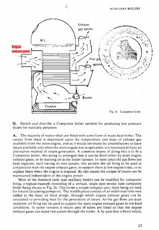
Q. Sketch and describe a Composite boiler suitable for producing low pressuresteam for auxiliary purposes.
A. The majority of motor ships are fitted with some form of waste heat boiler. Theoutput from these is dependant upon the temperature and mass of exhaust gasavailable from the main engine, and as it would obviously be unsatisfactory to havesteam available only when the main engine was in operation. it is necessary to have analternative method of steam generation. A common means of doing this is to fit aComposite boiler. this being so arranged that it can be fired either by main engineexhaust gases. or by burning oil in the boiler furnace. In most cases the gas flows arekept separate. each having its own uptake. this permits the oil firing to be used inconjunction with the engine exhaust gases. to support them at low engine loads. or toreplace them when the engine is stopped. By this means the output of steam can bemaintained independent of the engine power.
Most of the standard tank type auxiliary boilers can be modified for compositefiring, a typical example consisting of a vertical, single pass smoke tube compositeboiler being shown in Fig . 26. This forms a simple compact unit, there being no needfor forced circulating pumps etc . The modification consists of an additional tube nestadded to the basic oil fired design , through which engine exhaust gases can becirculated so providing heat for the generation of steam . As the gas flows are keptseparate, oil firing can be used to support the main engine exhaust gases at low loadconditions. In some versions a return pass of tubes are fitted so that the engineexhaust gases can make two passes through the boiler. A by-pass line is fitted which.
23
AUXILIARY BOILERS
with a suitable changeover valve. enables the boiler to be isolated from the mainengine exhaust if desired . This would be necessary for example at low engine powersin order to prevent undue fouling of the gas side heating surfaces that would tend tooccur if the exhaust gases were allowed to fall below their dew point temperatureduring their passage through the boiler.
In a few cases alternatively fired boilers are fitted, these differing from compositeboilers in that the two gas streams are not separated, the engine exhaust gases beingled into the boiler furnace and then following the same path as the flue gases.Although this gives a very simple arrangement, it makes the operation of the boilermuch less flexible as the engine exhaust gases must be completely by-passed from theboiler before oil firing commences, and vice versa.
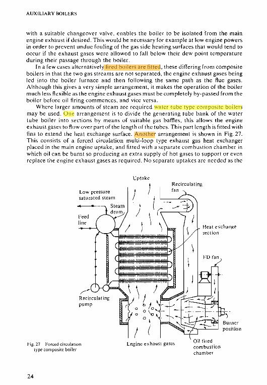
Where larger amounts of steam are required water tube type composite boilersmay be used . One arrangement is to divide the generating tube bank of the watertube boiler into sections by means of suitable gas baffles, this allows the engineexhaust gases to flow over part of the length of the tubes . This part length is fitted withfins to extend the heat exchange surface. Another arrangement is shown in Fig . 27.This consists of a forced circulation multi-loop type exhaust gas heat exchangerplaced in the main engine uptake, and fitted with a separate combustion chamber inwhich oil can be burnt so producing an extra supply of hot gases to support or evenreplace the engine exhaust gases as required. No separate uptakes are needed as the
Uptake
Low pressuresaturated steam
Feedlint"
Fig. 27 Forced circulationtype composite boiler
24
Engine exhaust gases Oil firedcombustionchamber
AUXILIARY BOILERS
combustion chamber can be pressurised by its own air supply so preventing theengine exhaust gases from interfering with the combustion of the oil.
Composite boilers form a simple waste heat system for the continuous generationof steam for auxiliary purposes, with the advantage of the boiler being kept inoperation both at sea and in port, so avoiding long periods of shut down which canoften result in corrosion problems.
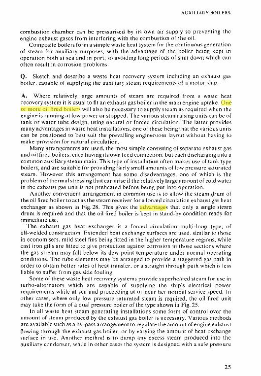
Q. Sketch and describe a waste heat recovery system including an exhaust gasboiler, capable of supplying the auxiliary steam requirements of a motor ship.
A. Where relatively large amounts of steam are required from a waste heatrecovery system it is usual to fit an exhaust gas boiler in the main engine uptake. Oneor more oil fired boilers will also be necessary to supply steam as required when theengine is running at low power or stopped. The various steam raising units can be oftank or water tube design, using natural or forced circulation. The latter providesmany advantages in waste heat installations, one of these being that the various unitscan be positioned to best suit the prevailing engineroom layout without having tomake provision for natural circulation.
Many arrangements are used, the most simple consisting of separate exhaust gasand oil fired boilers, each having its own feed connection, but each discharging into acommon auxiliary steam main. This type of installation often makes use of tank typeboilers, and are suitable for providing fairly small amounts of low pressure saturatedsteam. However this arrangement has some disadvantages. one of which is theproblem of thermal stressing that can arise if the relatively large amount of cold waterin the exhaust gas unit is not preheated before being put into operation.
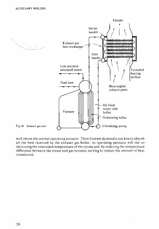
Another convenient arrangement in common use is to allow the steam drum ofthe oil fired boiler to act as the steam receiver for a forced circulation exhaust gas heatexchanger as shown in Fig. 28. This gives the advantages that only a single steamdrum is required and that the oil fired boiler is kept in stand-by condition ready forimmediate use.
The exhaust gas heat exchanger is a forced circulation multi-loop type, ofall-welded construction. Extended heat exchange surfaces are used, similar to thosein economisers, mild steel fins being fitted in the higher temperature regions, whilecast iron gills are fitted to give protection against corrosion in those sections wherethe gas stream may fall below its dew point temperature under normal operatingconditions. The tube elements may be arranged to provide a staggered gas path inorder to obtain better rates of heat transfer, or a straight through path which is lessliable to suffer from gas side fouling.
Some of these waste heat recovery systems provide superheated steam for use inturbo-alternators which are capable of supplying the ship's electrical powerrequirements while at sea and proceeding at or near her normal service speed. Inother cases, where only low pressure saturated steam is required, the oil fired unitmay take the form of a dual pressure boiler of the type shown in Fig. 25.
In all waste heat steam generating installations some form of control over theamount of steam produced by the exhaust gas boiler is necessary. Various methodsare available such as a by-pass arrangement to regulate the amount of engine exhaustflowing through the exhaust gas boiler, or by varying the amount of heat exchangesurface in use. Another method is to dump any excess steam produced into theauxiliary condenser. while in other cases the system is designed with a safe pressure
25
AUXILI ARY BOILERS
Uptake
-.
Fig, 28 Exhaust gas unit
Exhaus t gasheat exc hanger
Low pressuresaturated stea m
Ou tlethead er
Main engineexhaust gases
Oil firedwater tubeboiler
Generating tubes
Circulating pum p
Extendedhea tingsurfa ce
we ll above th e no rm al ope ra ting pr essure , Then if stea m dem and is too low to absorball th e heat rece ived by th e exhaust gas boiler, its o pe ra ting pr essure will rise soincre asing th e sa tura tion temperature o f th e steam and, b y reducing th e temperaturedifference be twee n the stea m and gas strea ms, servin g to re d uce th e a mo unt of he att ra nsfe rre d .
26
CHAPTER 3
Q. Discuss the reasons for the general adoption of wat er tube boilers in place of theScotch boiler for the supply of main engine steam .
A. With the demand for higher efficiencies, steam temperatures have stead ilyincreased, and this for various reasons is coupled with an increase in boiler pressure .
A boiler forms a more efficient heat exchanger if it co nsists of a large numberof small diameter tubes, rather than a small number of large diameter tubes.
A basic design factor involved in these points is the tube diameter ; the reasons forthi s are as follow s:
Thin Shell Formula
pressure x diameterStress = '------"----,--,,.....,---
2 x thickness
Thus for a given maximum stress, as pressure increases, the diameter must decreasein order to keep the thickness within reasonable limits .
Conduction Formula
temperature difference x area x timeHeat conducted = -----'-----:-:--:-------
thickness
Other factors remaining constant: as thickness decreases so heat conducted In
creases .
Surface Area
A number of sm all diameter tubes offer a greater heat exchange surface per unitlength th an a comparable large diameter tube, i.e. four 50 mm diameter tubes haveapproximately equal cross-sectional area to one 100 mm diameter tube, but ha vetwice as much surface a rea per unit length.
Thus the use of sma ll diameter tube enables higher pressures to be used , whilestill allowing thin tube walls, which together with the greater heat exchange su rfaceavail able, e na ble the heat evolved by the burning fuel to be more readily transmittedto the boiler water-thus a llowing high evaporation rates.
In addition the th in walled tubes are easier to manufacture , to bend, and toexpand a nd bell-mouth into drums and head ers . They also reduce the weight of metalin the boiler.
27
WATER TUBE BOILERS
The small amount of water in th e boiler also reduces the overall weight of theboiler and, together with the small diameter tubes, reduces the danger in the event ofa tube failure, but gives the disadvantage of little reserve water and ste am in theboil er, and thus efficient control is required for water level , etc.
The high rate of he at transfer across the thin tube walls , together with the sma llbore , demands rapid and positive wat er circulation through tubes, etc. Water tubeboile rs can be de signed to give suffic ient natural cir cul ation up to very high pressuresby sloping the tub es by at least 15° from the horizontal , a nd by the use of unheateddown comers to supply water to the lower parts of the boiler.
The small bore tubes demand pure feed conditions to prevent scale formation ,which could lead to blockage and overheating. In addition the thin metal thicknessgives littl e allowance for corrosion , and care must be taken to reduce this to aminimum on both gas and water sides o f the boiler. These factors give ano therdisad vantage in that elab orate closed feed syste ms must be used in conjunction withwater tube boilers.
The flexibility of wat er tube boilers, co upled with their positive circulation , andreduced amo unts of ref ractory material a llow for rapid steam raising.
The layout of the water tube boiler permits the furnace to be de signed togive etticient combustion condition s, and also allows the boiler shape to be modifiedto some ex te nt to fit the space available in the ship.
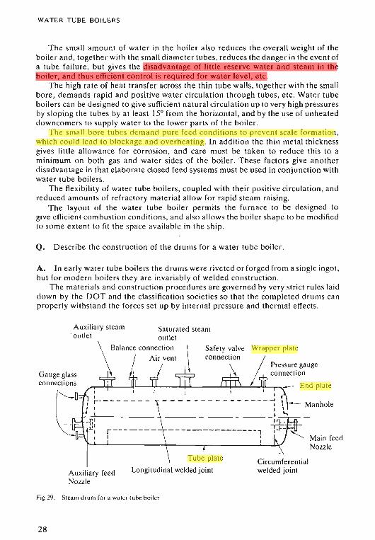
Q. Describe the con struction of the drums for a water tube boiler.
A. In early water tube bo iler s the drums were riveted or forged from a single ingot ,but for modern boilers the y ar e invariably of welded co nstructio n.
The materials and con struction procedures are governed by very strict rul es laiddown by the DOT and th e classification societies so that the completed drums canproperly withstand the forces set up by internal pressure and thermal effects.
Main feedNozzle
Manhole
Circumferentialwelded joint
Safety valveconnection
Tube plate
Longitudinal weldedjoint
Saturated steamoutlet
\ Balance connection\ ! Ai/ent
Wrapper plate
/ Pressure gauge/ lti connection
/"T---J.+I-----.JlIL---J.l.\---..L.f...J.....-----L....I....l...J.....I..-~..1,Il-~- End plateI
Ir --------I
J I.--r-,I-- - - - --L!I
II
Auxiliary steam. outlet
Auxiliary feedNozzle
Gauge glassconnections
Fig 29. Steam drum fo r a water lube boile r
28
WATER TUBE BOI L ERS
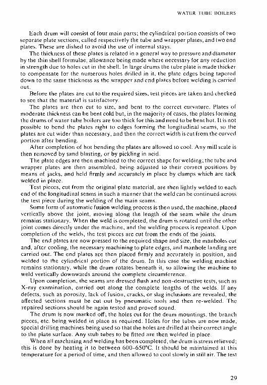
E ach drum will consist of four main parts ; the cylindrical portion co nsists of twosep ar ate plate sec tions, ca lled respectively the tube and wrapper plates, and two endplat es. These are d ished to avoid the use of internal sta ys.
The thickness of these plates is related in a general way to pressur e and diamet erby the thin shell formulae, allowance being made wher e nece ssar y for an y reductionin stre ng th due to holes cut in the shell. In lar ge drums the tube plat e is mad e th ickerto compen sat e fo r the num er ou s holes drill ed in it. the plate edges being tap er eddown to the sa me thickness as the wrapper and end plates before welding is carri edout.
Before the plates are cut to the required sizes, te st pieces are taken and checkedto see tha t the materi al is sa tisfacto ry .
Th e plates a re then cut to size , and bent to th e co rrect cur vature. Plat es ofmod er ate thickn ess can be bent cold but , in the majority of cases, the plates formingthe drums of water tube boil er s are too thi ck for this an d need to be bent hot. It is notpos sibl e to bend th e plates right to edges fo rming the longitud inal seams, so theplates are cut wider than necessar y, and th en th e co rrec t width is cut from the curvedportion afte r bend ing.
After completi on of hot bending the plat es are allowed to cool. An y mill scale isthen removed by sa nd blasting, or by pickling in acid .
Th e plate ed ges are then machined to the correct sha pe fo r welding; the tube andwrapper plates a re then asse mb led, be ing. adjusted to their correct posit ion s bymeans of jacks, and held firml y and accur ately in place by clamps which are tackweld ed in place.
Te st pieces, cut from the original plate material , ar e th en lightl y welde d to ea chend o f the longitud inal sea ms in such a manner th at the weld can be co ntinued acrossthe test piece during the weld ing of the main sea ms.
Some form of automatic fusion welding pro cess is then used, the machine, pla cedverti cally above th e joint, movin g along th e length of the seam whil e the drumremains sta tionary. Wh en the weld is complet ed , the drum is rotated unt il the o the rjoint comes directl y und e r the mach ine , and the welding process is rep eated. U po ncomp le tion of the welds , the test piece s ar e cut from th e ends of the joints.
Th e end plates ar e now pre ssed to the req uir ed shape and size, the manholes cutand, aft er coo ling, th e necessary machining to plate edges, and manhole landing ar ecarried o ut. The end plates are then placed firml y and accurately in position , andwelded to the cylind rica l portion of the drum. In this case the weld ing machinere ma ins sta tionary, while the drum rotates beneath it, so allowing the machine toweld vertica lly downwards around the complet e circumfer ence .
Upon comple tion, the seams are dressed flush and non-dest ructive tests, such asX-ray examination , carried out a long the complete len gth s of the welds. If anydefe cts, such as porosity, lack of fusion, cracks, or slag inclusio ns are revealed, theaffec ted sections mu st be cut out by pneumat ic tools and then re-welded. Th erepaired sections should be again tested and proved sound .
The drum is now marked off; th e holes cut for the drum mountings, th e br an chpieces, et c. being weld ed in place as requ ired . Hol es for the tubes a re now mad e ,special d rilling mach ines being used so th at the holes are dr illed at their co rrect angl eto the plate surface. An y stub tubes to be fitted are then weld ed in plac e.
When all machining and welding has been completed, the d rum is stress relieved ;this is done by heating it to between 600- 650°C. It sho uld be maint ained at thistemperature for a pe riod of time, and then allowe d to coo l slowly in still air. Th e test
29
WATER TUBE BOILERS
pieces, previously cut from the ends of the longitudinal joints, undergo the same heattreatment. They are then cut up to provide the required test specimens. Whensatisfactory reports on the results of these tests have been received, the drums areprepared for hydraulic testing. Where no stub tubes are to be welded, the tube holesmay be drilled after the hydraulic test has been completed.
Q. Discuss the functions of drums and headers as used in water tube boilers.
A. The vast majority of water tube boilers consist of a steam drum, one or morewater drums, and a number of headers. These components are interconnected bynumerous tubes.
These drums and headers may be considered as follows:
Steam Drum
In natural circulation boilers the motive power to provide a strong positrvecirculation is obtained by the difference in density between water at differenttemperatures.
Thus the steam drum provides a reservoir of relatively cool water giving thegravitational head necessary. to displace the high temperature mixture of steam andwater, with its much smaller density, from the heated tube surfaces. The drum thenprovides the space for the separation of this steam and water mixture as it returns.Again the difference in density allows the dry steam to rise, and leave from the top ofthe drum, while the water joins the incoming feed, to enter the downcomers and sorejoin the circulation circuit within the boiler.
The steam drum thus contains a reserve of steam for manoeuvring purposes. Italso receives the incoming feed water so giving the head of water necessary for theproper operation of the boiler, and provides for the distribution of this water to thedowncomers.
Water Drum
This provides for the distribution of water, entering it from the downcomers, to thescreen and generating tubes and in some cases to the water wall headers.
It also provides a space for the accumulation of suspended solids which may beprecipitated from the boiler water. The blow down connection enables these to beblown out as required.
Headers
These perform a similar duty to that of the drums, only size forming a distinctionbetween them. In general the drums are large enough to be entered throughmanholes, whereas access to the interior of the headers is only provided by handholes.
General Design Features The drum thickness is related to working pressure anddiameter in a general way by the thin shell formulae. Thus the smaller the drumdiameter for a given pressure, the thinner the plate sections that can be used, giving alighter and cheaper drum. However, if it is made too small difficulties arise with the
30
WATER TUBE BOILERS
separation of the steam and water within the drum. In some cases special steam andwater separators have to be fitted to overcome this problem.
Too small a drum can also cause problems with the control of the boiler waterlevel. In some cases this can lead to severe fluctuations of the water level duringmanoeuvring conditions.
The drums and headers also provide the tube plates necessary for the attachmentof the tubes. The drums are normally formed of two complete plate sections formingthe cylindrical portion, and in order to provide allowance for the reduction instrength due to the holes drilled in the tube plate, it is usually of greater thickness,being tapered down in way of the welded joints.
The headers may be cylindrical or rectangular in section, the latter being possibledue to the small overall dimensions which enable the flat surfaces involved towithstand the stresses imposed upon them by the internal pressure, without having tobe of undue thickness.
Q. Give the various types of tubes used in water tube boilers, together with theirmain functions.
A. The following types of tubes are used in water tube boilers:
Generating Tubes
These consist of numerous small diameter tubes placed in the main flow of hot gases,so forming a large heat exchange surface; the generation of steam takes place mainlyby convection.
For a given rate of water circulation the minimum allowable tube diameter islimited, as below a certain value the ratio of steam to water becomes excessive andleads to possible overheating.
Another limitation is imposed by the fact that, while sufficient heat exchangesurface must be provided for the gas exit temperature to be low enough to ensureeconomic operation, if there is too much the gases will fall below their dew pointtemperature. This will lead to corrosion of the heating surfaces.
In general the number of generating tubes tends to be reduced in modern boilers,until indeed in radiant heat boilers no generating tubes as such are fitted. Water wallsreceiving radiant heat are used instead.
Screen Tubes
These are placed adjacent to the furnace, so receiving heat from the flame togetherwith heat from the hot gases leaving the furnace; therefore they need a relativelylarge diameter to keep the ratio of steam to w.ater low enough to preventoverheating.
The duty of the screen tubes is to protect the superheater tubes from the directradiant heat of the furnace flame.
Water Wall Tubes
These are used basically to contain the heat of the furnace, thus reducing the amountof refractory material required.
In some types of boilers, water cooled refractory walls are used. These consist oftubes with studs welded onto them, covered with refractory material, which can now
31
WATER TUBE BOILERS
withstand the high temperatures without damage . In other designs part of the tubesurface is exposed to radiant heat which helps to generate steam. In some radiantheat boilers the tubes are welded together along their length by fins or strips, and norefractory is required.
Downcomer Tubes
These consist of large diameter, unheated tubes placed outside the gas stream whichact as feeders to the water drum and headers.
Riser or Return Tubes
These return steam and water from the top water wall headers to the steam drum.
Superheater Tubes
These consist of small diameter tubes placed in the main gas stream, after the screentubes. Their duty is to superheat the saturated steam leaving the drum to atemperature suitable for use in the main turbines. They must be protected fromdirect radiant heat as they are liable to overheating due to the much smaller specificheat of steam compared to that of water.
Superheater Support Tubes
These relatively large diameter tubes act basically as water cooled supports for thesuperheater tubes.
The metal surface temperature of all these boiler tubes must be considered and,for all tubes containing water, the working temperature is assumed to be thesaturation temperature corresponding to the boiler pressure, plus 15°C. Thussolid-drawn mild steel tubes can be used. In the case of superheater tubes, however,the temperature is considered to be the maximum superheat temperature, plus avalue in the order of 30°C for convection type superheaters, and in excess of thisfigure for radiant heat type superheaters. For steam temperatures above 455°C heatresisting alloy steel, containing small amounts of chrome and molybdenum, must beused.
In the majority of cases boiler tubes are expanded, and then bell-mouthed intodrums or headers. For large diameter tubes, such as downcorners, grooved seats areused to assist the expansion in forming a tight seal. Where high temperatures areinvolved, as with superheater tubes, welding may be used in place of expanding.
There are three main methods of arranging boiler tubes :Straight tubes are easy to clean and replace but can only be used in conjunction
with headers as, if used with drums, the tubes will not enter perpendicular to the tubeplate, and the holes would have to be recessed, or arbored, in order to keep thebell-mouthing near the drum surface. These recesses would act as stress risers, andare banned.
Curved tubes can be used with drums, but even here the tubes will not normallyenter perpendicular to the tube plate, but at an angle ; this makes expanding moredifficult, and also results in a thicker tube plate.
In the third method , often referred to as bent tube, all the tubes are bent so as toenter perpendicular to the surface of the tube plate. This gives the advantage of
32
WATER TUBE BOILERS
easier expansion and bell-mouthing, and also enables a thinner tube plate to be used.The disadvantage lies in the relatively sharp bends, which make cleaning and tubereplacement more difficult, and also means more spares must be carried as tubecurvature varies from row to row. However, the high quality feed available formodern boilers, which gives little risk of scale formation, enables this method to beused to advantage.
Q. Sketch and describe a header type water tube boiler. Give tube sizes and showthe position of the superheater. Indicate the gas and water flows , and give the gastemperatures from furnace to funnel.
A. The header type boiler is robust and suitable for use with poor quality feed ; thestraight relatively short tubes allow good internal cleaning, and easy tube replacement.
The main disadvantages are the large number of handhole doors in the headers,and extensive furnace brickwork.
Steam generation is mainly by convection , only the lower rows of screen tubesbeing subjected to radiant heat.
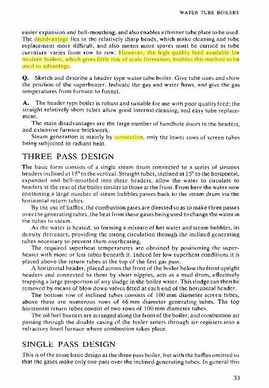
THREE PASS DESIGNThe basic form consists of a single steam drum connected to a series of sinuousheaders inclined at 150 to the vertical. Straight tubes, inclined at 150 to the horizontal,expanded and bell-mouthed into these headers, allow the water to circulate toheaders at the rear of the boiler similar to those at the front. From here the water nowcontaining a large number of steam bubbles passes back to the steam drum via thehorizontal return tubes.
By the use of baffles, the combustion gases are directed so as to make three passesover the generating tubes, the heat from these gases being used to change the water inthe tubes to steam.
As the water is heated, so forming a mixture of hot water and steam bubbles, itsdensity decreases, providing the strong circulation through the inclined generatingtubes necessary to prevent them overheating.
The required superheat temperatures are obtained by positioning the superheater with more or less tubes beneath it. Indeed for low superheat conditions it isplaced above the return tubes at the top of the first gas pass.
A horizontal header, placed across the front of the boiler below the front uprightheaders and connected to them by short nipples, acts as a mud drum, effectivelytrapping a large proportion of any sludge in the boiler water. This sludge can then beremoved by means of blow down valves fitted at each end of the horizontal header.
The bottom row of inclined tubes consists of 100 mm diameter screen tubes,above these are numerous rows of 46 mm diameter generating tubes. The tophorizontal return tubes consist of two rows of 100 mm diameter tubes.
The oil fuel burners are arranged along the front of the boiler, and combustion airpas sing through the double casing of the boiler enters through air registers into arefractory lined furnace where combustion takes place.
SINGLE PASS DESIGNThis is of the same basic design as the three pass boiler, but with the baffles omitted sothat the gases make only one pass over the inclined generating tubes. In general this
33
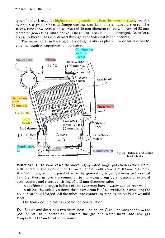
WAT ER TU BE BOI LERS
type of boil er is used for higher stea ming conditions th an the three pass and, in orderto obta in a grea ter heat e xchange surface , sma ller diameter tubes a re used . Thescreen tubes now consist of two rows of 50 mm diameter tubes, with rows of 32 mmdiamet er gene rating tubes abo ve . The return tubes rema in un changed . As before,access to these tubes is obta ined through handholes cut in the head er s.
The superheater in th e single pass design is always placed low down in order togive the requi red supe rheat temperatures.
Combustionair fromFD fan
Steam drum/
Generatingtubes32 mm dia.
Gas baffle _.,
Frontheader ..»
Combustionair
Uptake
Furnace
1300°C
r
Superheater
Double casingFig. 30 Ba bcock and Wilcox
header boiler
Water Walls In so me cases the more highly rat ed single pass boil er s have wat erwalls fitted at the sides of the furnace . These wa lls co nsist of 83 mm diameter,studde d tub es, runn ing par allel with the generat ing tubes between two verticalheaders; these in turn are connected to the steam drum by a number of e xte rn aldowncomer s and risers consistin g of 112 mm diameter tubes.
In addition the lar gest boilers of this type may have a water cooled re ar wall.In all but the o ldes t ver sion s, the steam drum is of all-we lde d construct ion; the
headers are so lid forged. All th e tubes, and co nnecting nipples, are solid-drawn mildste el.
The boiler double cas ing is o f bolted co nstructio n.
Q. Sket ch and descr ibe a two d rum, bent tube boil er. Give·tube sizes and show thepos itio n of the superheater. Indicate the gas and water flow s, and give gastemperatu res from furn ace to funn el.
34
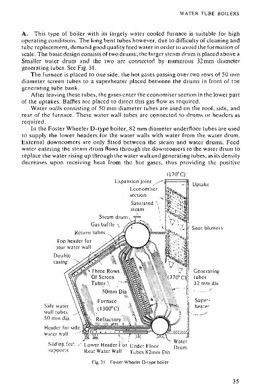
WATER T UB E BO ILE RS
A. This type of boiler with its lar gely wate r coo led furnace is suitable for highope ra ting conditio ns . The long bent tubes however, du e to difficulty of cleaning an dtube repl acem ent , dem and good qu ality fee d water in orde r to avoid the form ati on ofscale. The basic design consists of two drums; th e lar ger stea m drum is placed ab ove aSmaller wate r d rum and the two are conn ected by numerous 32 mm diam etergenerating tubes . See Fig . 31.
Th e furn ace is placed to one side , th e hot gase s passi ng ove r two rows of 50 mmdiameter screen tubes to a superheater placed between th e drums in front of thegenerating tube ba nk.
After leaving these tubes, the gases e nter the economise r section in th e lower partof the uptakes. Baffles a re placed to direct thi s gas flow as requ ired .
Water walls consis ting of 50 mm diam et er tubes are used on the roof, side , andrear of the furn ace . These water wall tubes are connected to drums or header s asrequired .
In the Fos te r Wh eeler D-type boiler, 82 mm diameter unde rfloo r tubes are usedto supply th e lowe r header s for the water walls with water from the water drum.External down come rs are only fitted between the stea m and water drums . Feedwater entering th e stea m drum flows through the dow ncom er s to the water drum toreplace the water rising up through the water wall and generating tubes, as its densit ydecreases upon receiving heat from the hot gases, th us pro vidin g the positive
Genera t ingtubes32 mrn di a.
/
Up take
Soot blow ers
Superheat er
" ' ---~
Expans ion joint ./ -F==~
Eco no misersect ion
Stea m drum
Gas baftle IReturn tu bes <,
T op head er forrear wa ter wa ll
Double
_. . I
Sliding feet / Low er Head er For Un der Fl oo rsupport s Rear Wate r Wall T ubes 82 111 m Dia
Header for sid e ~~!~~~~!i=~~~_.).~~Jwater wall 1!
Side waterwa ll tubes50 rum dia.
Fig. 31 Foster Wheeler D- type boiler
35
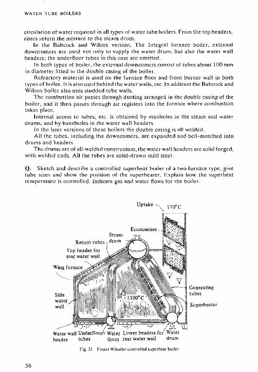
WATER TUBE BOILERS
circulation of water required in all types of water tube boilers. From the top headers,risers return the mixture to the steam drum.
In the Babcock and Wilcox version, The Integral furnace boiler, externaldowncomers are used not only to supply the water drum, but also the water wallheaders; the underfloor tubes in this case are omitted.
In both types of boiler, the external downcomers consist of tubes about 100 mmin diameter fitted in the double casing of the boiler.
Refractory material is used on the furnace floor and front burner wall in bothtypes of boiler. It is also used behind the water walls, etc. In addition the Babcock andWilcox boiler also uses studded tube walls.
The combustion air passes through ducting arranged in the double casing of theboiler, and it then passes through air registers into the furnace where combustiontakes place.
Internal access to tubes, etc . is obtained by manholes in the steam and waterdrums, and by hand holes in the water wall headers.
In the later versions of these boilers the double casing is all welded.All the tubes, including the downcorners, are expanded and bell-mouthed into
drums and headers.The drums are of all-welded construction, the water wall headers are solid forged,
with welded ends. All the tubes are solid-drawn mild steel.
Q. Sketch and describe a controlled superheat boiler of a two furnace type; givetube sizes and show the position of the superheater. Explain how the superheattemperature is controlled. Indicate gas and water flows for the boiler.
Uptake~ 1700C
36
SteamReturn tubes I drum
Top header forrear water wall
Sidewaterwall
->Water wall Underfloorv Water Lower headers for Waterheader tubes drum rear water wall drum
Fig. 32 FOSler Wheeler controlled superheat boiler
Generatingtubes
Superhea ter
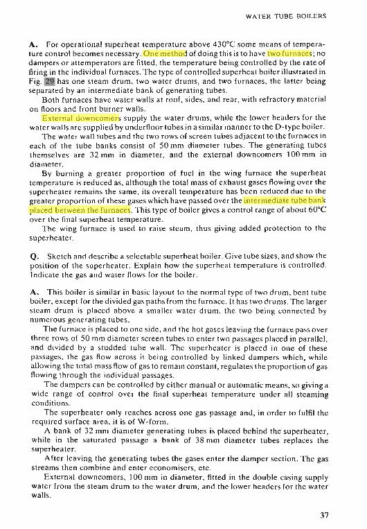
WATER TUBE BOILERS
A. For operational superheat temperature a bove 430°C so me mean s of temperature contro l becomes necessary. One method of doing th is is to have two furn aces ; nodamper s o r attempera to rs are fitted , the temperature being co ntro lled by the rat e offiring in th e individual furn aces. Th e type of controlled superhea t boiler illustrat ed inFig. 29 has one stea m drum, two wat er drums, and two furn aces, th e latter beingsepa ra te d by an intermediat e bank of generating tubes.
Both furn aces have wa te r walls at roof, sides , and rear , with refr actory mat erialo n floor s and front burner wall s.
External downcom er s supply the water drums, while the lower he ad er s for thewater walls are supplied by underfloor tubes in a simil ar manner to the D-type boiler.
The wat er wall tubes and the two rows of screen tubes adjacent to th e furn aces ineach of th e tube banks con sist of 50 mm diameter tubes. Th e gen er ating tubesthemselves are 32 mm in diameter, and the external down com er s 100 mm indiam et er.
By burn ing a gre ater proportion of fuel in the wing furn ace th e superhea ttemperature is reduced as, although the total mass of exhaust gases flow ing ove r th esuperhea ter re ma ins the same, its overall temperature has been reduced due to thegreater proportion of these gases which have passed over the intermedi ate tu be ba nkplace d between the furnaces. This type of boiler gives a control range of abo ut 60°Cove r th e final superheat temperature.
Th e wing furn ace is used to raise steam, thus giving added protect ion to thesuperheater.
Q. Sket ch and describe a se lectable superheat boiler. Gi ve tube sizes, and show thepositi on of the super heate r. Explain how the superheat temperature is contro lled .Indicate th e gas and wat er flows for the boiler.
A. T his boi le r is similar in basic layout to the normal type of two drum, bent tubeboiler , exce pt fo r the divided gas paths from the furnace . It has two drums. Th e lar gersteam drum is placed above a sma lle r wa te r drum, the two being connec ted bynum er ou s gene ra ting tubes.
Th e furn ace is place d to o ne side , and the hot gases lea ving th e furn ace pass ove rthree rows of 50 mm diam et e r screen tubes to ente r two passage s placed in parallel,and d ivided by a studde d tube wall. The supe rhea te r is placed in on e of th esepassages, the gas flow across it be ing controlled by linked dampers which , whil eallowing the total mass flow of gas to rem ain consta n t, regulates the proportion of gasflowing throu gh the individua l passages.
Th e damper s ca n be controlled by e ithe r manual or automatic means, so giving awide ran ge of contro l over th e fina l superhe at temperature under all steamingconditions.
Th e supe rheate r only rea ches across one gas passage and, in order to fulfil therequired surface a rea, it is of W-f'orm .
A bank of 32 mm diam et er gen er at ing tubes is placed behind the superheater,while in the sa tura ted passage a bank of 38 mm diameter tubes replaces thesuperheater.
After leaving the gene ra ting tubes the gases ente r th e damper section. The gasstr eams then combine and ente r econo mise rs, e tc .
External downcomers, 100 mm in diam et er, fitted in the double casing supplywater from the steam drum to th e wa ter drum, and th e lower heade rs for the waterwalls.
37
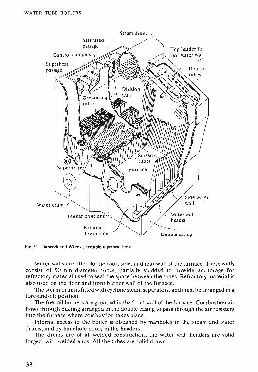
WATER TUBE BOILERS
Steam drum
Saturatedpassage
Control dampers
Externaldowncomer
Fig. 33 Babcock and Wilcox selectable superheat boiler
Top header forrear water wall
./
Double casing
Water walls are fitted to the roof, side, and rear wall of the furnace. These wallsconsist of 50 mm diameter tubes, partially studded to provide anchorage forrefractory material used to seal the space between the tubes. Refractory material isalso used on the floor and front burner wall of the furnace.
The steam drum is fitted with cyclone steam separators, and must be arranged in afore-and-aft position.
The fuel oil burners are grouped in the front wall of the furnace. Combustion airflows through ducting arranged in the double casing to pass through the air registersinto the furnace where combustion takes place.
Internal access to the boiler is obtained by manholes in the steam and waterdrums, and by handhole doors in the headers.
The drums are of all-welded construction; the water wall headers are solidforged, with welded ends. All the tubes are solid drawn .
38
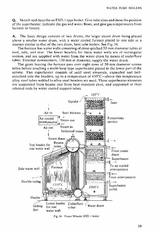
WATER TUBE BOILERS
Q. Sketch and describe an ESD.I type boiler. Give tube sizes and show the positionof the superheater. Indicate the gas and water flows, and give gas temperatures fromfurnace to funnel.
A. The basic design consists of two drums, the larger steam drum being placedabove a smaller water drum, with a water cooled furnace placed to one side in amanner similar to that of the two drum, bent tube boilers. See Fig. 34.
The furnace has water walls consisting of close-pitched 50 mm diameter tubes atroof, side, and rear. The lower headers for these water walls are of rectangularsection, and are supplied with water from the water drum by means of underfloortubes. External downcomers, 130 mm in diameter, supply the water drum.
The gases leaving the furnace pass over eight rows of 50 mm diameter screentubes before reaching a multi-loop type superheater placed in the lower part of theuptake. This superheater consists of mild steel elements, expanded and bellmouthed into the headers, up to a temperature of 455°C-above this temperaturealloy steel tubes welded to alloy steel headers are used. These superheater elementsare suspended from beams cast from heat-resistant steel, and supported at theirinboard ends by water cooled support tubes .
II
Air in
Air outItSteam drum
ReturnTop header for tubesrear water wall
Side water wall
~
Double casing
Header
Slidingfeet
Fig. 34 Foster Wheeler ESD. I boiler
Inlet
From steamdrumSuperheater
To air cooledattemperator
From atternperator
Superheateroutlet
39
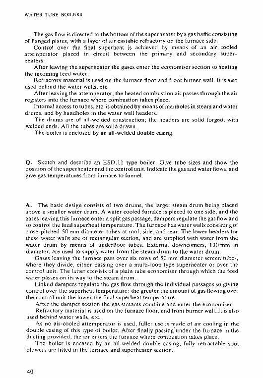
WATER TUBE BOILERS
The gas flow is directed to the bottom of the superheater by a gas baffle consistingof flanged plates, with a layer of air castable refractory on the furnace side .
Control over the final superheat is achieved by means of an air cooledattemperator placed in circuit between the primary and secondary superheaters.
After leaving the superheater the gases enter the economiser section so heatingthe incoming feed water.
Refractory material is used on the furnace floor and front burner wall . It is alsoused behind the water walls, etc .
After leaving the attemperator, the heated combustion air passes through the airregisters into the furnace where combustion takes place.
Internal access to tubes, etc. is obtained by means of manholes in steam and waterdrums, and by handholes in the water wall headers.
The drums are of all-welded construction ; the headers are solid forged, withwelded ends. All the tubes are solid drawn.
The boiler is enclosed by an all-welded double casing.
Q. Sketch and describe an ESD.ll type boiler. Give tube sizes and show theposition of the superheater and the control unit. Indicate the gas and water flows, andgive gas temperatures from furnace to funnel.
A. The basic design consists of two drums, the larger steam drum being placedabove a smaller water drum. A water cooled furnace is placed to one side, and thegases leaving this furnace enter a split gas passage , dampers regulate the gas flow andso control the final superheat temperature. The furnace has water walls consisting ofclose-pitched 50 mm diameter tubes at roof, side, and rear. The lower headers forthese water walls are of rectangular section, and are supplied with water from thewater drum by means of underfloor tubes. External downcomers, 130 mm indiameter, are used to supply water from the steam drum to the water drum.
Gases leaving the furnace pass over six rows of 50 mm diameter screen tubes,where they divide, either passing over a multi-loop type superheater or over thecontrol unit. The latter consists of a plain tube economiser through which the feedwater passes on its way to the steam drum.
Linked dampers regulate the gas flow through the individual passages so givingcontrol over the superheat temperature; the greater the amount of gas flowing overthe control unit the lower the final superheat temperature.
After the damper section the gas streams combine and enter the economiser.Refractory material is used on the furnace floor , and front burner wall. It is also
used behind water walls, etc.As no air-cooled attemperator is used, fuller use is made of air cooling in the
double casing of this type of boiler. After finally passing' under the furnace in theducting provided, the air enters the furnace where combustion takes place.
The boiler is encased by an all-welded double casing; fully retractable sootblowers are fitted in the furnace and superheater section .
40
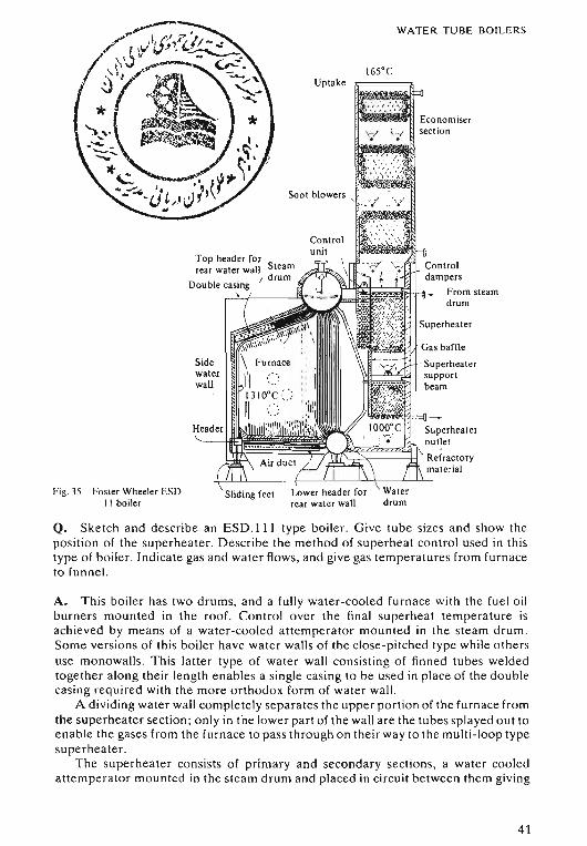
Controldampers
__ From steamdrum
Gas baffle
Superheatersupportbeam
Superheater
WATER TUBE BOILERS
165°CUptake
Soot blowers .
Sliding feet
Superheatero utlet
lSt1~~~~~9JllIt~~~~~J" Refractorymaterial
Sidewaterwall
Top header forrear water wall Steam
/ drumDou ble casing,
Fig. 35 Foster Wheeler ESD.II boiler
Q. Sketch and describe an ESD .111 type boiler . Give tube sizes and show thepo siti on of the superheater. Describe the method of supe rheat control used in thistype of boiler. Indicate gas and water flows, and give gas temperatures from furnaceto funnel.
A. This boiler has two drums, and a fully water-cooled furnace with the fuel oilburners mounted in the roof. Control over the final supe rheat temperature isachieved by means of a water-cooled attemperator mounted in the steam drum .Some ver sions of this boiler have water walls of the close-pitched type while othersuse rnonowalls. This latter type of water wall con sisting of finned tubes weldedtogether along their length enables a single casing to be used in place of the doublecasing required with the more orthodox form of water wall.
A dividing water wall completely separates the upper portion of the furnace fromthe superheater section ; only in the lower part of the wall are the tubes splayed out toenable the gase s from the furnace to pass through on their way to the multi-loop typesuperheater .
The superheate r consi sts of primary and secondary sections. a water cooledattemperator mounted in the steam drum and placed in circuit between them giving
41
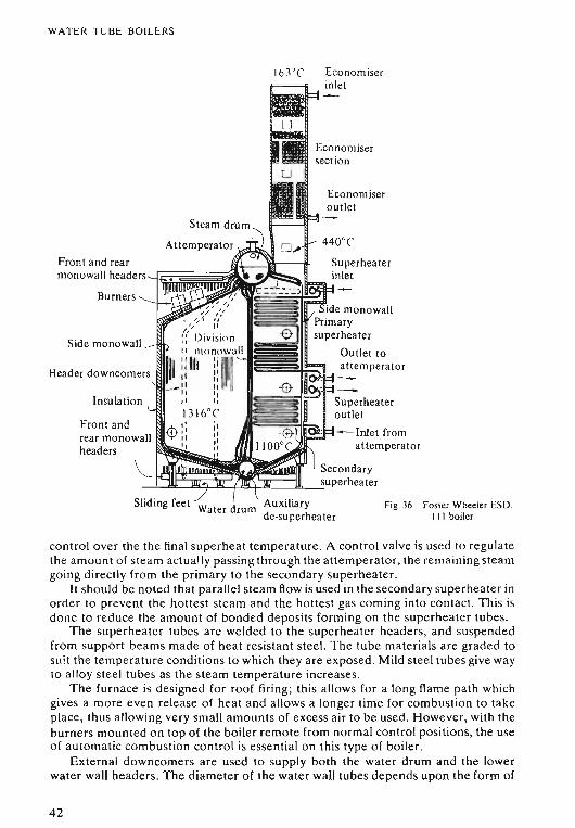
WATER TUBE BOILERS
Economiseroutlet
Economiserinlet
-Inlet fromattemperator
'-:~~~~~~~~~~~l~seCOnda ry_ superheater
Burners
163°('
Insulationl..
Front andrear monowallheaders
Front and rear i~~~~~d~~~~;lmonowall headers-,
Side monowall
Header downcomers lilll
Sliding feet Water drum Auxiliaryde-superheater
Fig. 36 Fosler Wheeler ESD.III boiler
control over the the final superheat temperature. A control valve is used to regulatethe amount of steam actually passing through the atternperator, the remaining steamgoing directly from the primary to the secondary superheater.
It should be noted that parallel steam flow is used in the secondary superheater inorder to prevent the hottest steam and the hottest gas coming into contact. This isdone to reduce the amount of bonded deposits forming on the superheater tubes.
The superheater tubes are welded to the superheater headers, and suspendedfrom support beams made of heat resistant steel. The tube materials are graded tosuit the temperature conditions to which they are exposed. Mild steel tubes give wayto alloy steel tubes as the steam temperature increases .
The furnace is designed for roof firing; this allows for a long flame path whichgives a more even release of heat and allows a longer time for combustion to takeplace, thus allowing very small amounts of excess air to be used. However, with theburners mounted on top of the boiler remote from normal control positions, the useof automatic combustion control is essential on this type of boiler.
External downcomers are used to supply both the water drum and the lowerwater wall headers. The diameter of the water wall tubes depends upon the form of
42
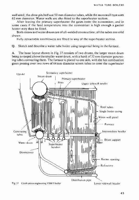
W A T ER TUB E BOILERS
wall used ; the close pitched use 50 mm diameter tubes, while the monowall type uses62 mm diameter. Water walls are also fitted to the superheate r section.
Aft er leav ing the prim ar y supe rhea te r the gases ent er the eco nomiser, and insome cases if the feed temperature into the eco nomiser is high enough a gas/airheat er may then be fitted.
Both stea m and water drums are of all-w elded con struction ; all the tubes are so liddrawn .
Fully retractable soo tblowers are fitted in way of the sup erheater secti on .
Q. Sketch and describe a water tube boiler using tangential firing in the furn ace.
A. The basic layout shown in Fig. 37 consi sts of two drums, the larger steam drumbeing arranged above the smaller water drum, with a bank of32 mm diameter genera ting tube s conn ecting them. The furn ace is placed to one side, with the hot combustiongases passing over two rows of 64 mm diameter screen tubes to enter the superhea ter
Up ta ke Seco nda ry supe rhea te rStea m d rum
Ge ne ra tingtub es
Fig. 37 Co mbusti on engineering VSM 9 boiler
Roof tu bes
Single bo iler casing
Furn ace
Intermedi at e hea de r
Beam suppo rt
Burner ope ning
Refr actor y
Distri hution pipe "',Lower sidewall header
43
WATER TUBE BOILERS
placed in front of the generating tube bank. The superheaters are mounted vertically togive good drainage, and to avoid horizontal surfaces onto which slag deposits canbuild up.
To avoid the formation of bonded deposits on the gas surfaces of the superheatertubes, the metal temperatures are reduced by preventing the hottest gas and steamflows coming together. The hottest gases first enter the primary superheater and itslower steam temperatures, before flowing on to the secondary superheater with itshigher steam temperatures. An attemperator mounted in the steam flow line betweenthe two superheater sections provides control over the final superheat outlet temperature.
The boiler is supported at mid-height by a saddle beneath the water drum, and bysupports under the intermediate waterwall headers placed level with the water drum.The furnace lies partly above and partly below these intermediate headers, so beingable to expand both upwards and downwards from the point of support.
Gastight diaphragm walls ofwelded construction completely surround the furnace,reducing the need for refractory material, and allowing the use ofa single boiler casing.The burners placed in the lower portion of the furnace are arranged for tangentialfiring by mounting them in each corner of the rectangular furnace, with each burneraligned tangential to a circle of about 0·6 m diameter in the centre of the firing space.This allows the formation of a horizontal vortex flame pattern providing increasedturbulence and an effectively longer flame path, both ofwhich lead to efficient combustion with low levels of excess air, so greatly reducing corrosion and deposits in the gaspassages .
Positive water circulation in the boiler is provided by external downcomers whichfirst feed the water drum and then from there the lower water wall headers. This waterthen rises through the water wall tubes to the intermediate headers which serve tobalance the distribution of water to the upper sections of the water walls, where risersfrom the top headers to the steam drum complete the circulation path. The generatingbank is supplied directly from the water drum.
Economisers are mounted in the uptake after the generating tubes , and if required arotary air heater can be fitted as a final stage heat exchanger.
Q. Describe some of the design features of radiant heat type water tube boilers.
A. The ESD.lll type boiler shown in Fig. 36 forms a typical example of a radiantheat boiler. These have no banks of generating tubes. relying instead upon water wallswhich completely surround the furnace, receiving radiant heat for the generation ofsteam . In a few cases tangential type water walls are fitted, but in general diaphragmwalls are preferred; these form a water box type furnace and require only a single boilercasing . Many versions of radiant heat boilers use welded tube attachment, and in thiscase only a single boiler drum is required, with a header being fitted in place of thewater drum. This is because internal access is not required in order to expand the lowerends of the tubes.
The majority of radiant heat boilers use roof firing which, by providing a longerflame path, allows a greater time period for the combustion process to be completedwithin the confines of the furnace . This provides for more efficient combustion withreduced excess air requirements, below 5% as compared to the 5% to 15% needed fornormal side-fired furnaces. As a result there is a less intense but more even release ofheat, avoiding local high temperature regions which could be detrimental to the
44
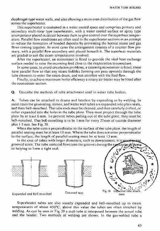
W ATER TUB E BOILERS
diaphragm type water walls, and also allowing a more even distr ibution of the gas flowacro ss the superheater.
Th is superhea ter is conta ined in a water cooled space and co mprises primar y andsecondar y multi-loop type superheaters, with a water cooled sur face or spray typeattemperato r placed in circuit between them to give control over the superhea t temperature . Parallel flow conditions are often used in the superheater sections in an atte mptto reduce the formati on of bonded deposits by preventing the hottest steam and gasflows coming together. In most cases the arrangement con sists of a cou nter flow primary, with a parallel flow secondary unit placed beneath it. Th e superhea t material sare graded to suit the steam temperatures involved.
After the superhea ter, an economiser is fitted to provide the vital heat exchangesurface needed to raise the incoming feed close to the evapo ration temperature.
In some cases , to avoi d circulation problems, a steaming economiser is fitted; thesehave parallel flow so that any steam bubbles forming can pass upward s through thetu be clements to enter the steam drum, and not inte rfere with the feed flow.
Finally, to achieve maximum boiler efficiency a rot ary ai r hea ter may be fitted afterthe economiser section.
Q. Describe the method s of tube attachm ent used in water tube boiler s.
mentGrooved sea tEx panded and bell mou th ed
A. Tu bes can be atta ched to drums and headers by expa nding or by welding. Inmost cases the generating, screen, and water wall tub es are expand ed into plain sea ts,and then bell-mouthed . The tube ends must be cleaned , and then care fully dr ifted, orrolle r expa nded into the holes in the tub e plat e . Th ey must project th rough the tub eplate by at least 6 mm. To prevent tubes pull ing out of the tube plat e, they must bebell-mouthed. This bell-mouthing is to be I mm for every 25 mm of outside diameterplus 1'5 mm . See Fig. 38.
Wh en the tube enters perpendicular to the surface of the tube plate , the length ofparallel seating must be at least 10 mm . Wh ere the tu be does not ente r perpendicularto the surface, the length of parallel seating must be at least 13 mm .
In the case of tubes with larger diameter s, such as downcomers, it is.w;oIoft!!-oH~Sf
grooved sea ts. The tube material flows into the grooves during the e ~sir~.t'a~@5ii:
so helping to form a tight seal. ;...!::J~ 1.'.,..,.~.. -.. v-::.. -~~h.1.'\ .,!i\ ~I 'J( ~~ *
o ~ ~.~\:.~ ~r'~j*~ '*" .~,, ~ ;T
- .:;..... " ( . .\~ ' \ .•.'".. _ ( • ~ I , t .J . .0:..1
Fig. 38 E~ded tube a"nacb -. . '
Superheater tubes are also usually expa nded and bell -mouthed up to steamtemperatures of about 450°C ; above th is value the tubes are ofte n a ttached bywelding. As can be seen in Fig. 39 a stub tube is interposed between the ac tua l tubeand the header. Two meth ods of welding are shown. In the gas-welded tu be a
45
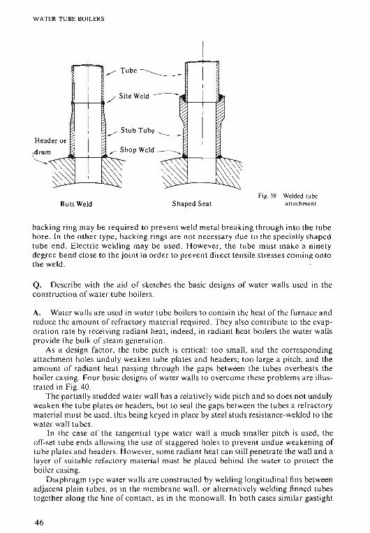
WATER T UBE BOILERS
,--- Tu be ____________
Header or
(drum ~rl'l!f--j.-~......._"--....
Butt Weld Shaped SeatFig. 39 Welded tube
a ttac hment
ba cking ring may be required to prevent weld metal breaking through into the tubebore . In the o ther type , ba ck ing rin gs are not necessar y du e to the specially shapedtube end. Ele ctri c welding may be used. H owever , the tube must make a ninetyde gree bend close to the joint in ord er to prevent dir ect tensile stresses coming ontothe weld.
Q. Describe with the aid of sketches the basic designs of water walls used in theconstruction of water tube boilers.
A. Water walls are used in water tube boilers to contain the heat of the furn ace andredu ce the am ount of refracto ry mat erial required. Th ey a lso contribute to the evapo ra tio n rate by receiving rad iant heat ; indeed, in radiant heat boilers the wat er wallspro vide the bulk of steam generation .
As a design fact o r, the tube pitch is crit ical: to o sma ll, and the co rrespo ndingattachment holes undul y weaken tube plates and headers; too large a pitch, and theamo unt of radiant heat pas sing throu gh the ga ps between the tubes overhea ts theboile r ca sing. Fo ur basic designs of wa ter wall s to overco me these probl ems a re illustrated in Fig. 40.
The partially studded wat er wall has a relatively wide pitch and so do es not undulyweaken the tube plates or headers, but to seal the ga ps between the tubes a refracto rymater ial mu st be used , th is being keyed in place by steel studs resistance-welded to thewat er wall tubes.
In the case of the tangent ial type water wa ll a much sma ller pitch is used , theoff-set tube end s a llowing the use of staggered holes to prevent undue weakening oftube pla tes and head ers. However , som e radiant heat can still penetrate the wall and alayer of suitabl e refactory mat erial mu st be placed beh ind the water to pr otect theboiler cas ing.
D iaphragm type water walls are con structed by welding longitudinal fins betwe enadjacent plain tubes, as in the membrane wall , o r alternati vely weld ing finned tubestogether along the line of co ntac t, as in the mon owall, In both cases similar gastight
46
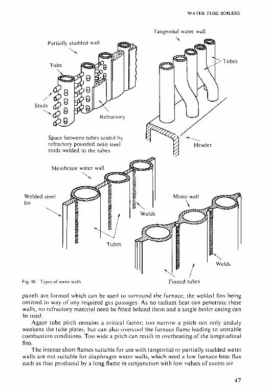
W ATER TUBE BOILERS
Ta ngential water wall
"
Tu bes
Tube
Space between tubes sea led byrefra ctory pounded onto steelstuds welded to the tubes
Parti ally studded wall<,
/Studs
<,
Welded stee lfin
Memb rane water wa ll ....:s:s:s::s:::!!~'==s'$S51<,
/"-
Welds
Fig.40 Types of wat er walls Finned tubes
pan els a re formed which ca n be used to surrou nd the furnace, the weld ed fins beingomitte d in way of any required gas passages. As no radiant heat ca n pe netra te thesewall s, no refractory materi al need be fitted behind them and a sing le bo iler cas ing canbe used .
Again tube pitch remains a cr itica l fac to r; too narrow a pitch no t on ly undulyweakens th e tube plates, but ca n a lso overcool the furnace flame lead ing to un stableco m bustion conditio ns. Too wide a pitch can res ult in ov er heating of the lo ngitudinalfins.
The intense sho rt flam es suita ble for usc with tan genti al o r partiall y studded wat erwa lls are not suita ble for diaphragm water wall s, which need a low furnace heat fluxsuc h as th at produced by a lon g flam e in co njunction with low values of excess air
47
WATER TUBE BOILERS
A disadvantage of diaphragm walls is that tube failures are difficult to repair,simple plugging of the failed tubes no longer being suitable as the single casing, havingno refractory, would rapidly overheat. Instead, an immediate welded repair of thedamaged tubes must be performed before the boiler can be returned to service.Another problem arises in the event of an explosion within the furnace, which wouldnow act directly upon these gaslight panels, distorting them, and in serious casespulling tubes from their attachments.
48
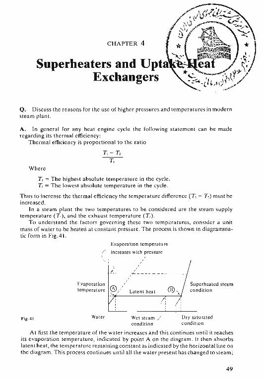
CHAPTER 4
-x,.Superheaters and Upta-...........
Exchangers
Q. D iscuss the reasons for the use of higher pre ssures and temperatures in mod ernsteam plant.
A. In general for any heat engine cycle the following statement can be mad eregard ing its thermal efficien cy:
Thermal efficiency is proport ion al to the rati o
TI - T2
T I
Where
T I = The highest absolute tempe rature in the cycle.T2 = The lowest absolute temper ature in the cycle.
Thus to increase the thermal efficien cy the temper ature d iffere nce ( T I - T2 ) must beincreased.
In a steam plant the two temperat ures to be co nside red are the stea m supplytemperature (TI ) , and the ex haust temperatu re (T2) .
To under stand the fact or s gove rni ng these two temper atures, consider a unitma ss of wa ter to be heated at co nsta nt pressure. The process is shown in diagrammatic form in Fig. 41.
Evapora tio n temper atu re
( increases wit h pressure
Evaporationtemperature
,I,,
Lat ent hea t ® "\I ' I ,
I ! :
Superheated steamco ndit io n
Fig . 4 \ Water Wet stea m /co ndi tio n
Dry satu ra te dco ndi t io n
At first the temperature of the wate r incre ases and th is co ntinues unt il it rea che sits evap orat ion temperature , ind icated by point A o n the diagram . It th en absorbslatent heat , the temper ature rem aining co nsta n t as indicated by th e horizontal line onthe d iagram. Th is process continues unt il all the wat er present has chan ged to steam;
49
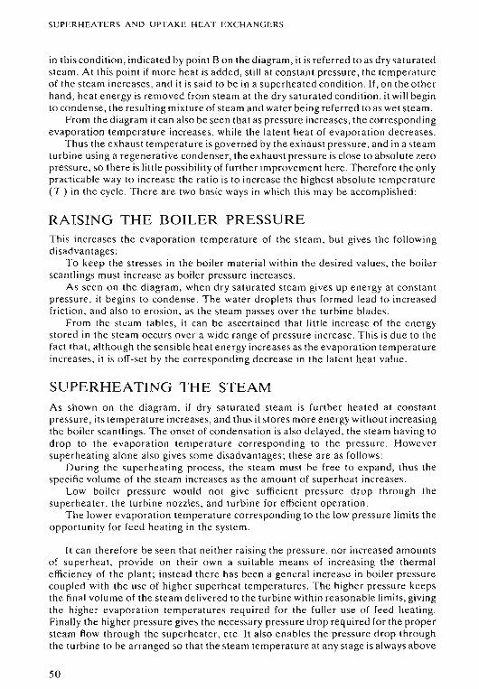
SUPERHEATERS AND UPTAKE HEAT EXCHANGERS
in this condition, indicated by point B on the diagram, it is referred to as dry saturatedsteam . At this point if more heat is added, still at constant pressure , the temperatureo f the steam increases, and it is sa id to be in a supe rhea ted condition . If, on the o the rhand , heat energy is removed from steam a t the dry saturated condition , it will beginto condense , the resulting mixture of steam and water being referred to as wet steam.
From the diagram it can also be see n that as pressure increases, th e correspo nd ingevaporation temperature increases, while the latent heat of evaporati on de creases.
Thus the e xha ust temperature is go verned by the exhaust pressure, and in a steamturbine us ing a regenerati ve condenser, the exhaust pre ssure is close to absolute ze ropressure, so there is little possibility of further improvement here. Th erefore the o nlypr acticable way to increase the rati o is to increa se the highest absolute temperature(T,) in the cycle. There are two basic ways in which thi s ma y be acco mplished :
RAISING THE BOILER PRESSUREThis increases the evaporation temperature of the steam, but gives the foll owingd isadvantages :
To keep th e stresses in the boiler material within the desired values, the boil erscantlings mu st increase as boiler pressure increases .
As seen o n the diagram, when dr y saturated steam gives up en ergy at con st antpre ssure , it begins to co nde nse. The water dr oplets thu s formed lead to incr easedfricti on, and also to erosion, as the steam pa sses over the turbine blad es.
Fro m the steam tabl es, it can be ascertained that littl e increase o f the en ergystored in the stea m occurs over a wid e range of pressure increase . Th is is due to thefact th at, althou gh the se nsible heat energy incre ases as the evapo ra tion temperatureincreases, it is off-se t by th e corresponding decrease in the latent heat value.
SUPERHEATING THE STEAMAs shown on the diagram , if dry sa turated stea m is further heated at constantpressure, its temperature increases, and thus it stores more en ergy without increasingthe bo ile r scantlings. The o nse t of condensation is also delayed , the steam having todrop to the eva po ratio n temperature co rrespo ndi ng to the pres sure . Howe versuperhea ting alo ne also gives some disadvantages; these are as follow s:
During the supe rheating process, the steam must be free to expand, thus thespecific volume of the steam increases as the am ount of superheat increases.
Low boiler pressure would not give sufficient pressure drop through thesupe rhea ter, the turbine nozzles, and turbine for efficient o pera tio n.
The lower evapo ratio n temperature corresponding to the low pressu re limits theoppo rtunity for feed heating in the syst em.
It can therefore be see n th at neith er raising the pressure , nor incr eased amountso f supe rhea t, provide on the ir own a suitable means of increasing the thermalefficiency of the plant; instead there has been a general increase in boiler pressurecoupled with the use of higher superheat temperatures. The higher pressure keepsthe final volume of the ste am delivered to the turbine within reasonable lim its, givingthe higher evap oration temperatures required for the fuller use of feed heating.Fin ally the high er pressure gives the necessary pr essure drop required for the propersteam flow through the superheater, etc. It also en ables the pre ssure dr op throughthe turbine to be ar ra nged so that the ste am temperature at any stage is a lway s above
50
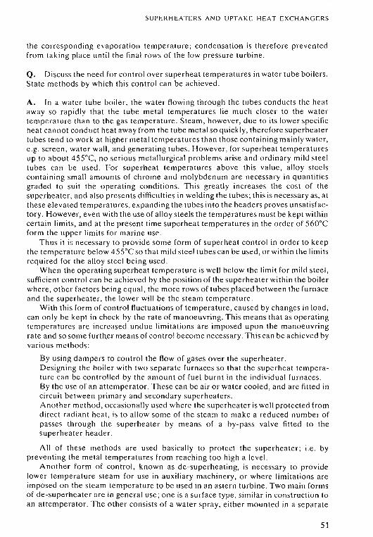
SUPERHEATERS A N D UPTAKE HEAT EX CHANGERS
the corresponding evapo ratio n temperature; condensation is therefore preventedfrom tak ing place until the final rows of the low pre ssure turbine .
Q. Discuss the need for control over superheat temperatures in water tube boilers.State methods by which this co ntrol can be achieved.
A. In a water tube boiler, the water flowing through the tubes conducts the heataway so rapidly that the tube metal temperatures lie much closer to the watertemper ature than to the gas temperature . Steam , however, due to its lower specificheat ca nno t conduct heat aw ay from the tube metal so quickly , therefore superheate rtubes tend to work at high er metal temperatures than those containing mainly water,e.g. scr een, water wall, and generating tubes. However, for superheat temperaturesup to abo ut 455°C, no serious metallurgical problems arise and ordinary mild steeltubes can be used . For superheat temperatures above this value, alloy steel scontain ing sm all amounts o f chrome and molybdenum ar e necessary in quantit iesgraded to suit th e operating conditions. Thi s greatly increases the cost of thesuperheater, and also presents difficulties in welding the tubes; this is necessary as, a tthe se elevated temperatures, expanding the tubes into the headers proves unsatisfactory. However, even with the use of allo y stee ls the temperatures must be kept withincertain limits, and at the present tim e supe rhea t temperatures in the order of 560°Cform the upper limits for marine use .
Thus it is ne cessary to provide some form of superheat co ntro l in o rder to keepthe temperature below 455°C so that mild stee l tubes can be used , or within the limitsrequired for the alloy ste el being used .
When the operating superheat temperature is well below the limit for mild steel ,sufficient control can be achieved by the position of the superheater within the boilerwhere, other factors being eq ua l, the more row s of tubes placed between the furn aceand the superheater, the lower will be the steam temperature.
With this form of control fluctu ati ons of temperature , caused by changes in load,can o nly be kept in check by the rate o f manoeuvring. This means th at as operatingtemperatures a re increased undue limitations are imposed upon th e manoeuvringrat e and so some further means of control become necessar y. This can be achieved byvari ous method s:
By using dampers to co ntro l the flow of gases over the supe rhea te r.De signing the boiler with two se pa rate furn aces so th at the superheat temperature can be controll ed by the amo un t o f fuel burnt in the individual furna ces.By the use of an atternperator. These can be air or water cooled , and are fitted incircuit between primary and secondary superheaters.Another method, occasionally used where the superheater is well protected fromdirect rad iant he at , is to allow so me of the stea m to make a reduced number ofpasses through the superheater by means of a by-pass valve fitted to thesupe rhea te r header .
All of these method s are used basic all y to protect the superheater ; i.e . bypreventing the metal temperatures from reach ing too high a level.
Another form of control, kn own as de-superheating, is nec essary to providelower temperature ste am for use in auxiliary machinery, or where limitations areimposed on the stea m temperature to be used in an ast ern turbine . Two main formsof de-superheater ar e in general use ; one is a surface type, simil ar in construction toan attemperator. The other con sists of a water spray, either mounted in a separa te
51
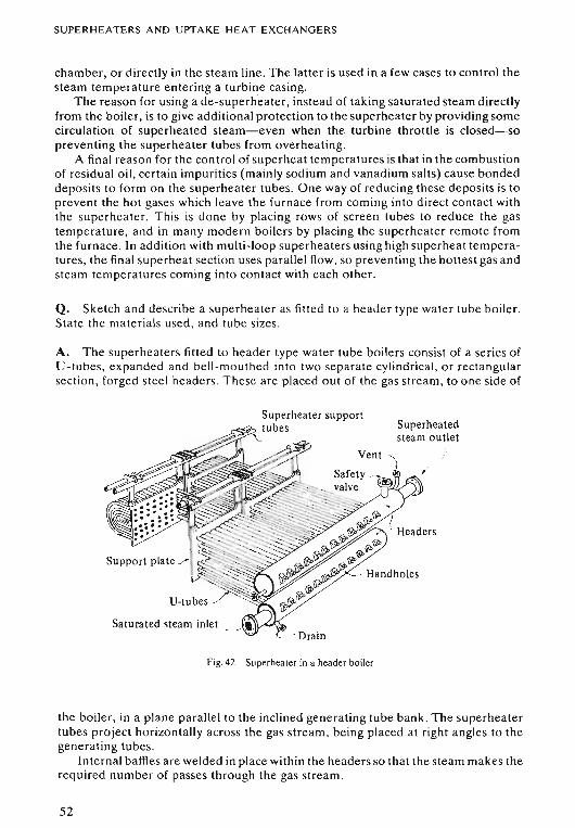
SUPERHEATERS AND UPTAKE HEAT EXCHANGERS
chamber, or directly in the steam line. The latter is used in a few cases to control thesteam temperature entering a turbine casing.
The reason for using a de-superheater, instead of taking saturated steam directlyfrom the boiler, is to give additional protection to the superheater by providing somecirculation of superheated steam-even when the turbine throttle is closed-sopreventing the superheater tubes from overheating.
A final reason for the control of superheat temperatures is that in the combustionof residual oil, certain impurities (mainly sodium and vanadium salts) cause bondeddeposits to form on the superheater tubes. One way of reducing these deposits is toprevent the hot gases which leave the furnace from coming into direct contact withthe superheater. This is done by placing rows of screen tubes to reduce the gastemperature, and in many modern boilers by placing the superheater remote fromthe furnace. In addition with multi-loop superheaters using high superheat temperatures, the final superheat section uses parallel flow, so preventing the hottest gas andsteam temperatures coming into contact with each other.
Q. Sketch and describe a superheater as fitted to a header type water tube boiler .State the materials used, and tube sizes.
A. The superheaters fitted to header type water tube boilers consist of a series ofU-tubes, expanded and bell-mouthed into two separate cylindrical, or rectangularsection, forged steel headers. These are placed out of the gas stream, to one side of
Support plate .>
Saturated steam inlet
Superheated
,
Fig .42 Superheater in a header boiler
the boiler, in a plane parallel to the inclined generating tube bank . The superheatertubes project horizontally across the gas stream, being placed at right angles to thegenerating tubes.
Internal baffles are welded in place within the headers so that the steam makes therequired number of passes through the gas stream.
52
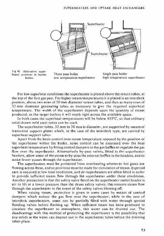
SUPERHEATERS AND UPTAKE HEAT EX CHANGERS
Fig. 43 Alternati ve superhea ter positions in header
boilersThree pass boilerlow temperature superheater
Single pass boilerhigh temperature superheater
For low superheat conditions the superheater is placed abo ve the return tubes, atthe top of the first gas pass. For higher steam temperatures it is placed in an interdeckposition, above two rows of 50 mm diameter screen tubes, and th en as many row s of32 mm diameter generating tubes as necessar y to give the required supe rhea ttemperature. Th e width 'of the supe rhea te r depends upon th e quantity of stea mproduced; in the larger bo iler s it will rea ch right acro ss the ava ilable space .
In both cases the supe rhe at temperatures will be below 455°C, so that ordinarysolid-d rawn mild stee l tubes can be used .
The supe rhea ter tubes, 32 mm to 38 mm in diameter , arc supported by means oftransverse suppo rt plates which, in the case of th e interdeck type , are carried bysupe rheat support tubes.
Apart from the basic contro l ove r steam temperature imp osed by the position ofthe superheater within the boiler , some control can be exercise d over the finalsuperheat temperature by fittin g control dampers in the gas baffles to re gulate the gasflow over the superheate r. Alternatively by-pass valve s, fitted to th e supe rhea terhe aders, allow some of th e stea m to by-pass the internal baffles in the headers, and somake fewer passes through th e supe rhea te r.
The superheaters must be pr ot ect ed from overheating whenever hot gases areflowing across them, and so prov ision mu st be made for circula tio n of ste am. Especialcare is requi red a t low load co ndi tions , and de-superheat ers are ofte n fitted in orderto provide sufficient stea m flow th rough the superheater under the se conditions.Another precaution is that the safe ty valve fitted on the supe rheater outlet header isse t to lift at a lower pressure th an the drum safety valves ; thi s en sur es steam flowthrough the superheater in the event of the safety valves blowing off.
When raising steam , pr ot ection is given in some cases by mean s of controldampers which reduce the gas flow over the superheater; while in th e case ofint erdeck superheaters, some can be partially filled with water th rough specialflooding valves before flash ing up . Wh en sufficient steam has been pr odu ced tocircul at e the superheater to atm osph er e , thi s water call be dr ained o ut. Th edisadvantage with this method of protect ing the superhea ter is the possibility thatany so lids in the water can deposit out in th e superhea te r tub es before th e drainingtakes place .
53
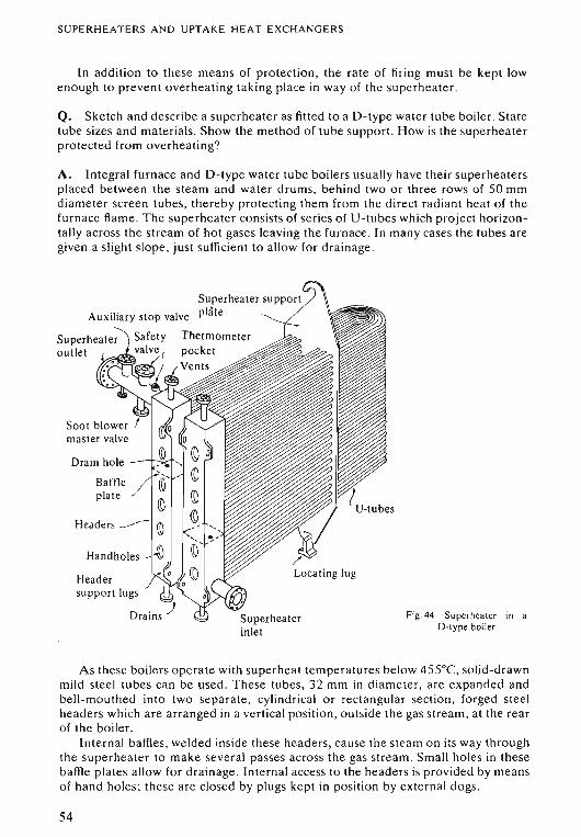
SUPERHEATERS AND UPTAK E HEAT EX CHANG ER S
ln addition to th ese means of protection, the rate of firing mu st be kept lowenough to pr event overheating taking place in way of the supe rheate r.
Q. Sketch and de scribe a sup erheater as fitted to a D-type water tub e boiler. Statetube sizes and materi als. Show the method of tube support. How is the supe rheate rprot ected from overheating?
A. Integral furnace and D-type water tube boilers usually have their superheater splaced between the stea m and water drums, behind two or three rows of 50 mmdiam et er screen tubes, thereby protecting them from the direct radiant heat of thefurn ace flame. The superheate r consists of se ries of V-tubes which proj ect horizontall y acro ss the stream of hot gases leaving the furn ace. In man y case s the tubes aregiven a slight slope, ju st sufficient to allow for dr ain age .
Bartl eplate
Handholes
Head ersuppo rt lugs
Drains -; Fig.44 Su perhea ter in aOotype boiler
A s th ese boilers operat e with sup erheat temperatures below 45 5°C, solid-drawnmild stee l tub es ca n be used . Th ese tubes, 32 mm in diamete r, are ex pa nde d andbell-mouthed into two se pa rate, cylindrical o r re ctangular sec tion, for ged steelheader s which arc arrange d in a vertic al position, outside the gas stream, at the rearof the boiler.
Internal baffles, welded ins ide these header s, ca use the stea m on its way throughthe superhea te r to make several passes across th e gas stre am. Sm all holes in thesebaffle plates allo w for drain age. Int ernal acce ss to the head ers is provided by meansof hand holes; these are closed by plu gs kept in positi on by ex ternal dogs.
S4
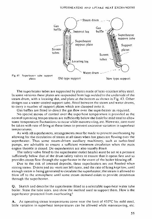
SUPERHEATERS AND UPTAKE HEAT EXCHANGERS
Old type support
Gasbaffle
",---
Screentubes
Fig. 45 Supe rheater lub e suppo rtplat es
,-- Steam drum . ..
Gasbaffle
Superheatersupport plate
Screen
~ . _.Water drum - -_.-.
New type support
Th e superhea te r tubes are supported by plates made of heat-resistant alloy stee l.In so me ve rsio ns these plates are suspended from lugs weld ed to the underside of thestea m drum , with a locating slot, and plate at the bottom as shown in Fig. 43 . Otherde signs use a water-cooled support tube, fitted between the ste am and water drums,to carry a number of support plates which are clamped onto it.
G as baffles are fitted to direct the gas flow over the superheater as required .No spec ial means of control over the superheat temperature is pro vided as the
normal o pe rating temperatures are sufficiently below the limit for mild stee l to allowso me temperature fluctuations to occur while manoeuvring, etc. However , care mustbe tak en with rate of firing at these times to prevent exce ssive vari ati on in supe rhea ttemperatures.
As with all superheaters, arrangements must be made to pr event overhe ating bya llowing for the circulation of steam at all times when hot gases are flowing over thesupe rhea te r. Thus some steam-driven auxiliary machinery, such as turbo-feedpumps, are advisable to ensure a sufficient minimum circul ation when the mainengine throttle is closed. De-superheaters are also usually fitted .
Th e safety valve fitted to the superheater outlet header must be se t at a pressu resufficiently below that of the drum safety valves to ensure th at it ope ns first and sopr ovides ste am flow through the superheater in the event of th e boiler blow ing off.
Du e to th e risk of internal deposits, these superheaters are not flooded whenraisin g stea m. Drains and air vents are left open, and the rate of firing kept low , untilen ou gh stea m is being generated to circulate the superheat er; th e stea m is allowed tobiow off to the atmosphere until some ste am dem and ex ists to pr ovid e circulationthrough the superheater.
Q. Sketch and describe the superheate r fitted to a se lectable superhea t water tubeboiler. State the tube sizes, and show the method used to suppo rt th em. H ow is th esupe rheate r protected from overheat ing?
A. As ope ra ting ste am temperatures come near the limit of 455 °C for mild stee l,little variation in superheat temperatures can be allowed while man oeu vr ing, etc.
55
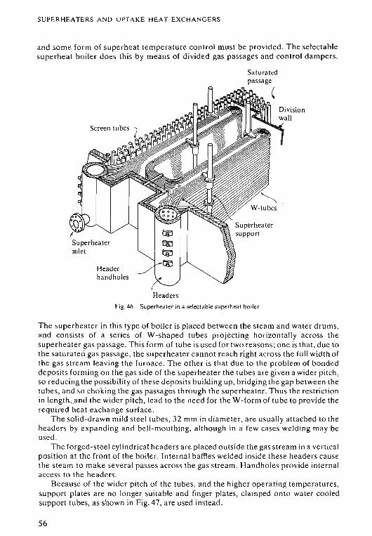
SUPERHEATER S AND U PT A K E HEAT EXCHANGERS
and some form of super heat temperature control must be provided . The selectablesupe rheat boil er does thi s by means of divided gas passages and control dampers.
Saturatedpassage,
Screen tubes (
Headerhandholes
HeadersFig.46 Superhea ter in a selectable superhea t boiler
The superheater in this typ e of boiler is placed between the stea m and water drums,and con sists of a se ries of W-shaped tubes pr oj ecting horizontally acro ss thesupe rhea te r gas passage. Th is form of tube is used for two reason s; on e is th at, du e tothe satura ted gas passage , the superhea te r cannot re ach right across the full width ofthe gas stream leaving the furnace. The o the r is that due to th e problem of bondeddeposits forming on the gas side of the supe rheater the tubes are given a wider pit ch ,so reducing the po ssibility of th ese deposits bu ild ing up , bridg ing the gap between thetubes, and so cho king the gas passages th rough th e superheater. Thus th e restrictionin lcngth .jmd the wider pitch , lead to the need for the W-form of tube to provide therequired heat exch ange surface .
The so lid -d rawn mild steel tubes, 32 mm in diam eter, are usually attache d to theheader s by expa nding and bell -mouth ing, although in a few cases welding may beused .
The forged-steel cylind rica l headers are placed outside the gas stream in a vertica lposition at the front of the boile r. Internal baffles weld ed inside these headers caus eth e ste am to make seve ra l passes across the gas stream. Handhole s provide internalaccess to the header s.
Because of the wider pitch of the tubes, and the higher opera ting temperatures,support plates are no longe r suita ble and finger plates, clamped onto water cool edsupport tubes, as shown in Fig. 47, a re used instead.
56
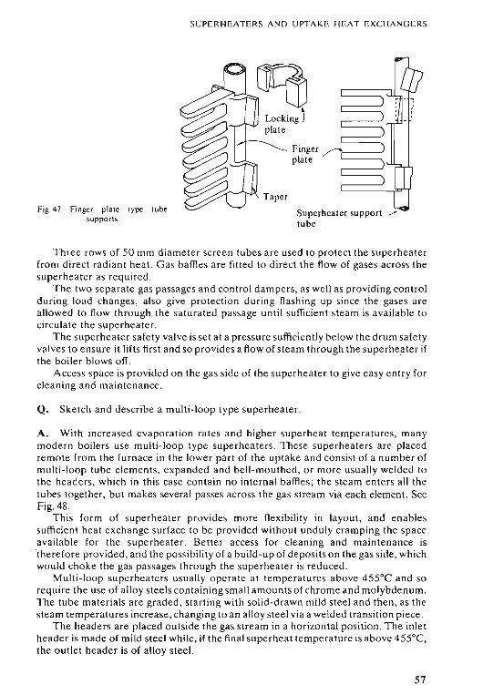
SUPERHEATERS AND UPTAKE HEAT EX CHANGERS
Fig. 47 Finger plate type l ubesuppor ts
Taper
Finger ~t==::::: .plate
Superheater support ./tube
Th ree row s of 50 mm diameter screen tubes are used to protect the superheaterfrom direct radiant heal. Gas baffles are fitted to direct the flow of gase s across thesuperhea ter as required .
The two se parate gas pa ssages and control dampers, as well as providing controlduring load changes, also give protection during flashing up since the gases areallowed to flow through the saturated passage until sufficient steam is ava ilable tocirculate the superheater.
The superheater safety valve is set at a pressure sufficientl y below the drum safetyvalve s to ensure it lifts first and so provides a flow of steam through th e superheater ifthe boil er blows off.
Ac cess space is provided on the gas side of the superhea te r to give ea sy entry forclea ning and maintenance.
Q. Sketch and describe a multi-loop type superheater .
A. With increased evaporation rates and higher supe rhe at temperatures , manymod ern boilers use multi-loop type superheaters. These superheate rs are placedrem ote From the Furnace in the lower part of the uptake and consist of a number ofmulti-loop tube elements, expanded and bell -mouthed , or more usually welded tothe headers , which in this case contain no internal baffles ; the steam enters all thetubes together, but makes several passes across the gas str eam via each element. SeeFig. 48 .
This form of superheater provides mor e flexibility in layout , and enablessuffi cient heat exchange surface to be provided without unduly cramping the spaceavailable for the superheater. Better access for cleaning and maintenance is'there fo re provided , and the pos sibility of a bu ild-up of deposit s on the gas side, whichwould choke the gas passages through the supe rheate r is reduced.
Multi-loop superheaters usuall y op er ate a t temperatures above 455°C and sorequire the use of alloy steels containing small amo unts of chro me and molybdenum.The tube materials are graded , starting with solid-drawn mild stee l and then, as thesteam temperatures increase, chang ing to an allo y steel via a welded transition piece .
The headers are placed outside the gas stream in a horizontal position . The inletheader is made of mild steel while , if the final superheat temperature is above 455°C,the outlet header is of alloy stee l.
57
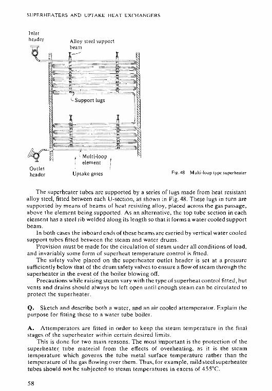
SUPERHEATERS AND UPTAKE H EAT EXCHANGERS
Inletheader
Outletheader
Alloy steel supportbeamx~j
r_:--F"" - ----=
~~~3L Support lugs
~~~" -=~~~-_.~~-_._--=. -:~~
j " Mult i-loopelement
Upt ake gases Fig. 48 Multi-loop type superhea ter
The superheater tubes are supported by a series of lugs made from heat resistantalloy steel , fitted between each U-sect ion , as shown in Fig. 48. These lugs in turn aresuppo rted by means of beams of heat resisting allo y, placed across the gas passage,above the element be ing supported. As an alternative, the top tube section in eachelement has a steel rib welded along its length so that it form s a water cooled supportbeam .
In both cases the inboard ends of these beams are carried by vertical water cooledsupport tubes fitted between the ste am and water drums.
Pr ovision must be made for the circul ati on of steam under all conditions of load ,and invari ably som e form of superhea t temperature control is fitted .
The safety valve pla ced on the superheater outlet header is set at a pressuresufficiently below that of the drum safety valves to ensure a flow of steam through thesuperheater in the event of the boiler blowing off.
Precautions while ra ising steam var y with the type of superhea t control fitted , butvents and drains should a lways be left open until enough stea m can be circulated toprotect the supe rheater.
Q. Sketch and describe both a water, and an air cooled attemperator. Expl ain thepurpose for fitting these to a water tube boiler.
A. Attemperators are fitted in order to keep the steam temperature in the finalstages of the superhea ter within ce rtain de sired limit s.
This is done for two main reasons. The most important is the protection of thesuperhea te r tube materi al from the effects of overheating, as it is the steamtemperature which governs the tube met al surface temperature rather than thetemperature of the gas flowing over them . Thus, for example , mild steel superheatertubes should not be subjected to steam temperatures in excess of 455°C.
58
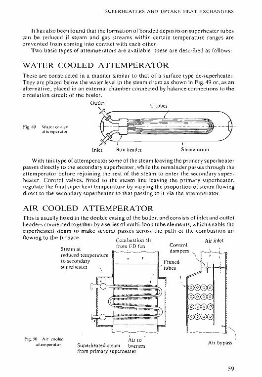
SUPE RHEATERS AND UPTAKE H EAT EXC H A NG E RS
It has also been found that the formation of bonded deposits on superheater tubescan be reduced if steam and gas streams within certain temperature ranges areprevented from coming into contact with each other.
Tw o ba sic types of attemperators are av ailable ; the se are described as foll ows:
WATER COOLED ATTEMPERATOR
Fig. 49 Water m illedau crnperator
These are co nstructed in a manner similar to that of a sur face type de-superheater.They a re placed below the water level in the steam drum as shown in F ig. 49 or, as analt ernative , pla ced in an external chamber connected by bal ance connections to thecirculation circuit of th e boiler.
Outlet U-tu oes
~ IW#._~-,-- jr.J
Inlet Box header Steam drum
With th is type of attemperator some of the stea m leaving th e primary superhea te rpasse s dir ectly to the secondary supe rhea ter , whil e the remainder passe s through theatte mpera tor before re join ing the rest of the steam to enter the seco ndary supe rheat er. Control valve s, fitt ed to the steam line leaving the primary supe rheate r ,regulate the final superheat temperature by va rying the proportion of stea m /lowingdirect to the seco ndary superhea ter to that passing to it via the att emperator.
AIR COOLED ATTEMPERATOR
Air bypass'"--- -" i)
Finned. tubes
.Air to
Superheated steam burnersfrom primary superheater
Steam atreduced temperatureto secondarysuperheater
Fig. 50 Air coo ledatt ernperator
This is usuall y fitted in the double cas ing of the boiler, and co nsists of inlet and outletheaders connected tog ether by a se ries of multi-loop tube eleme nts, whi ch en abl e thesupe rheated steam to make several passes across the path of the co m bustion a ir
Rowing to the furn ace . Combustion air Air inletfrom FD fan Control~~ dampers
" \
59
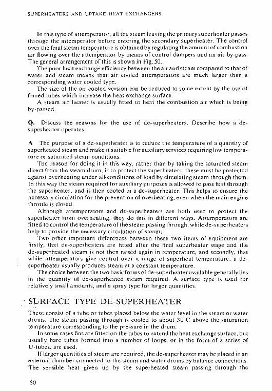
SUPERHEATERS AND UPTAKE HEAT EXCHANGERS
In this type of attemperat or , a ll the steam leaving the primary superheater pas sesthrough the attemperator bef or e entering the secondary supe rheater. The controlove r the final steam temperature is obtained by regulating the amount of combustionair flowing over the attemperator by means of control dampers and an air by-pass.The general arrangement of this is shown in Fig. 50.
The poor heat exchange e ffi ciency between the air and steam compared to that ofwater and steam means that air coo led attemperators are much larger than acorresponding water cooled type .
The size of the air cooled vcrs ion can be reduced to so me extent by the use offinned tubes which increase the heat excha nge surface .
A stea m air heater is usually fitted to heat the combustion air which is beingby-p assed .
Q. Discuss the reasons for the use of de-superheaters. De scribe how a desuperheater operates.
A Th e purpose of a de-superheater is to reduce the temperature of a quantity ofsuperheated ste am and make it suitable for auxiliary ser vices requiring low temperature or satura ted steam conditions.
The reason for doing it in this way, rather than by taking th e satura ted steamdirect from the stea m drum, is to prot ect the superheat er s; th ese mu st be protectedagainst ove rhea ting und er all- condi tions of load by circulating stea m through them.In this way the steam required for auxiliary purposes is allowed to pass first throughthe supe rhea ter , and is then cooled in a de-superheater. This helps to ensure thenecessary circulation for the prevention of overheating, even when the main enginethrottle is closed.
Although attempera to rs and de-sup erheaters are both used to protect thesuperheater from overheating, they do this in different ways. Attemperators arefitted to control the temperature of the stea m passing through , while de-superheatershelp to provide the necessar y circulation of steam.
Two other important differences between these two item s of equipment arefirstly, that de-superheaters are fitted afte r the final superheater stage and thede-superheated stea m is not then raised aga in in temperature , and secondly, thatwhile attemper ators give control over a range of superheat temperature, a desuperheater usually produces steam at a con stant temperature.
The cho ice be tween the two basic forms of de-superheater available gen er ally liesin the quantity of de-superheated steam required . A surface type is used forrelatively sm all amo unts, and a spray type for larger quantities.
SURFACE TYPE DE-SUPERHEATERThese consist of a tube or tubes placed bel ow the water level in the steam or waterdrums. The stea m passing through is cooled to about 30°C above th e sa turationtemperature correspo nding to the pressure in th e drum.
In some cases fins are fitted on the tubes to extend the heat exchange surface , butusually bare tubes formed into a number of loops , or in the form of a se ries ofU-tubes, are used.
If larger qu antities of steam are required , th e de- superheater may be placed in anexternal chamber connected to the steam and water drums by balance co nnectio ns.The sensible heat given up by the supe rhea ted steam passing through the
60
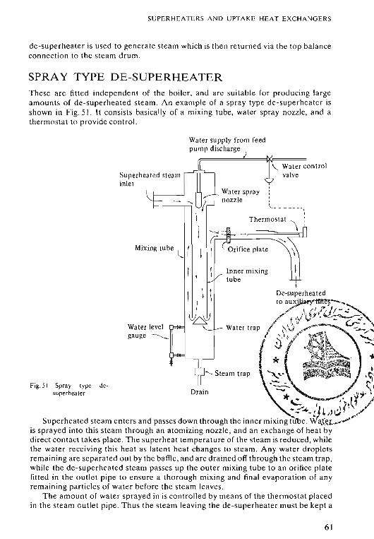
SUPERH EATERS AND UPTA KE HEAT E XC HA NG E RS
de-superheat er is used to ge nerate steam which is then return ed via the top balanceconnection to the steam drum .
SPRAY TYPE DE-SUPERHEATERThese are fitted independent of the boil er , and are su itable for producing largeamounts of de- superheated steam. An example o f a spray type de-superheat er isshow n in Fig. 51. It consists basically of a mixing tube, water spray nozzle, and athermos ta t to provide control.
\. Water contro lvalve
Inner mixingtube
_ Water spraynozzle .
I
Wa ter supply from feedpump discharge
I
I ~~- ~~~HJMixing tube (( ~ I (Orifice plate
1 I
1 \ \i
W&Water levelgauge ~
Superheated steaminlet
Spray type desuperhea ter
Fig. 51
De-superheatedtoau~--...
~.'" \ " I r . ! I _'~,. ' , :. ~J') V ; -
.../:""' ft"l ".,:' ..~:..- " " c..,..;;. ,Water trap I \'.\) <,~.-_ , -................
(/ S'(' ., ~ J:.:A~. ~
""" ;\tk'~~. ~i£~. ...'lie' . .
<; Steam trap ~..... :. .:.'.r .~.~~ \1Drain .".,_ •*c.. .,,- ,'. rJ ,.<
•: ... /1 L,;j f ..<,./Superheated ste am enters and passes down through the inn er mixing tube .WaXf<I..~-"""" ·
is sprayed into thi s stea m through an a to mizing nozzle , and an exc ha nge of he at bydir ect contact takes place . The su pe rhea t temper ature of the steam is reduced , whil ethe water receiving th is he at as latent heat chan ges to steam. An y water droplet srem aining are sep ar at ed out by the baffle, and are dr ain ed off through th e steam trap,while th e de-superheated steam pa sses up the outer mixing tube to an orifice platefitted in the outlet pip e to ensure a tho rough mixing and final evap orati on of an yremaining particles of wat er bef ore the steam leaves.
The amo unt o f wa ter sprayed in is co ntro lled by means of th e th erm ostat placedin the steam outle t pip e. Thus the steam leaving the de-superheater mu st be kept a
61
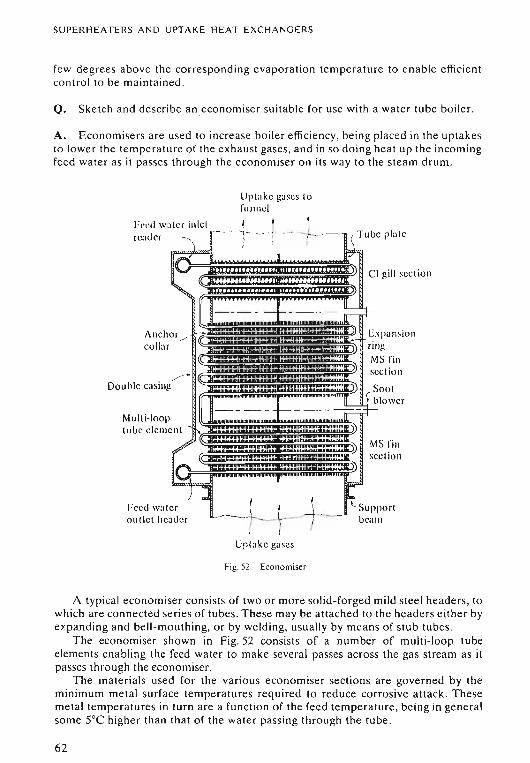
SUPERH EAT ERS AND U PT AKE H EAT EXC HANGERS
few degrees abo ve the co rresponding eva po ra tion temperature to ena ble efficientco ntro l to be maintained .
Q. Sketch and describe an eco nomiser suitabl e for use with a wat er tube boiler.
A. Econo misers are used to increase bo iler e fficiency, be ing placed in the uptak esto lower the temperature of the ex ha us t gases, an d in so doin g heat up the incomingfeed wa te r as it passes th ro ugh the eco nomise r on its way to th e stea m drum.
Upta ke gases tofunnel
Feed water inletreader
An chor "collar ~
. >
Double casing
Multi-looptu be cleme nt
Feed watero u t le t header
-L-·1._- -L.) ;
~+-. --L-( 1- (Up take gases
Fig , 52 Economiser
A typical econ omiser consists of two or more solid-for ged mild steel head er s, towhich are connected series of tubes. Th ese may be attached to the header s e ither byex pa nding and be ll-mo uthing, or by weld ing, usuall y by mean s of stub tubes.
Th e econ om iser shown in Fig. 52 co nsists of a number of multi-loop tubeelements enabling the feed water to mak e severa l pa sses ac ross the gas strea m as itpasses throu gh the ccono miser.
The mat eri als used for the vario us economiser section s are governed by theminimum metal surface temperatures required to reduce corr osive attack . Th esemetal temperatures in turn are a fun ction of the feed temperature , being in gene ra lso me 5°C high er than th at of the wate r passing through the tube.
62
SUPERHEATERS AN D UPTAK E H EA T E XCHANGERS
For feed temperatures above 13Soe plain , so lid -d rawn mild stee l tubes may beused, but it is usu al to weld mild steel fins or studs onto the tubes so as to e xte nd theirheat exch ange surface. If the feed water temperature lies between 115°C to 138°Ccast-iron gills a rc used . These completely cover the mild stee l tubes, thu s protectingthem from corrosiv e attack.
Th e tubes are supported by vertical tube plates forming th e sides of the uptake . Insome cases add itional intermediate tube support plates are fitted with in the upt ake.
A reli ef valv e must be fitted to the economiser if it can be isolat ed from the boiler.In many cases thi s is not possible since the feed check, and fee d regulato r are placedon the inle t to the econo mise r, which then forms an int egral part o f the boiler.
A ir vents must be provided for the release of air when filling the econo rnise r, orwhen raising ste am. Drain valves fitted to the lower headers e na ble the eco no mise r tobe emptied of water when required.
Efficient soot blowing arrangeme nts must be provided so as to keep the heatexc ha nge surfaces free from soot. This is important not only in the interests ofefficiency, but a lso to reduce the pos sibility of an upt ake fire starting in sootydeposits.
Suita ble access and the necessary fitt ings a nd dr a ins sho uld be provided for thewater washin g of the uptake heat e xchanger s when the boiler is shut down.
Q. Discu ss with respect to the efficient operation of eco no mise rs the imp ortance ofmaintaining both the gas and water temper atures a t their correct valu es.
A. Aft er leaving the last rows of generating tubes the e xha ust gases are s till atre la tive ly high temperatures, and heat excha ngers placed in the uptakes to reducethi s temperature lead to a gain in the ove ra ll thermal efficiency of the boiler.However, a practical limitation is imposed upon their use by the fact that if an y metalsurfaces in the uptakes fall below the 'de w point' temperature at which the watervapour in the exhaust gases condense, then any sulphur dioxide or trioxide present inth e ex haust gases, formed by the combust ion of any sulphur in the fuel, will beabso rbe d by the water. This results in the fo rmat ion of acidic deposits on any metalsur face s below 170°C. This acid can cau se corrosive attack on mild steel surfaces attemper atures below 138°C, and on cast iron at temperatures below 115°C.
The feed temperatures are also important as the metal temperatures involved area function of these feed temperatures, be ing in ge ne ra l some 5°C higher.
It is thus important to maintain the se minimum temperature values under allstea ming conditio ns. If the normal feed temper ature e ntering the economiser isa bo ut 140°C there is an a llowable margin ofso me 15-20oe,but the feed temperatureshould never be allowed to fall below the 115°C limit under steaming conditions; if itdoes, he avy fouling ca n oc cur in add ition to the co rros ive att ack , due to soot depositsbuilding up on the acid dew forming o n the cool met al su rfaces. Thus some meanssho uld be provided to maintain the feed temperatures ab ove these minimum valu es ;for example, by suppl ying e xtr a stea m 10 a deaerator in a sys te m where one of the se isfitted.
These points are vital as the gas temperature lea ving the economiser, provided itis above the dew point temperature , has little to do with fouling or corrosion as longas the metal temperatures are kept above the minimum value quoted.
The water temperature within the eco no miser should not be allowed to e xceed atemperature 30°C below the corresponding evaporation temperature ; thi s pre ventsthe formation of steam within the economiser.
63
SUPERH E ATERS AND UPTA KE HEA T E XC HA NGE RS
In many water tube boilers the gas temperatures leav ing the last rows ofgenerating tubes a re so intense that, due to the high ope rating temperaturesinvolved, the economiser forms an important part of the heat exchange surface of theboiler. Ind eed in som e radiant heat type boilers, the gases leaving the sup erheaterimmed iately enter the economiser and the gas temperature is so high that, in o rder toprevent the form ati on of stearn in the economiser, the direction of the water flow isreversed . These ar e referred to as ste aming econ omisers. Th e water enters at thebottom and then rise s parallel to the gas flow. Thi s has the effect of levelling out thetemperature gradient and helps to pr event steam forming in the economise r undernormal stea ming conditions.
Q. Sket ch and des cribe tubular type air heaters as fitted in the uptake of a watertube boiler. Discuss the limitations to the use of gas air heaters.
A. If the uptake temperatures warrant it a gas air heater may be placed in the boileruptake. However, if this is to be don e a critical factor to be conside red is that thetemperatures of the met al surfaces involved should remain above the dew pointtemperature of the exhaust gases under all conditions of load, in o rde r to avoid unduedeposits and/or corrosion taking place in the uptake . This often prohibits the use ofboth gas air heaters and economise rs a t the same time .
In Scotch boilers, and some header type water tube boilers, the gas temperatureleaving th e last rows of generating tubes is usually so low that only a gas air heater canbe fitted. In other typ es of water tube boilers the gas temper ature leaving thegenerating tubes is higher . and provided suffi cie nt feed heating is ava ilable to raisethe feed temperature ab ove 140°C economisers a re normally fitted . Gas air he aters,placed in the uptake as a final stage of heat extraction after the eco nomiser, can onlybe considered in a few cases as a viabl e proposition , i.e. where the feed temperatureente ring the economiser is above 200°C. .
If a choice exists, an economiser will normally be fitted due to the greaterefficiency of he at exchange between gas and water, than between gas and air.
When gas air heaters are fitted , those of tubular form are most widely used. Theseare of two ba sic types:
VERTICAL TUBE TYPEThese consist of se ries of vertical tubes, expanded into two horizontal tube plates. Inth is type the gas passes through the tubes while the air flows over the outside of them .Up to a certain point these are easy to keep clean. However, this cleaning processneeds to be carried out manually by me an s of brushes which are pu shed down thetubes when the boiler is shut down . Under ste aming conditions soo t blowers areused , but are not completely effective be cau se of the tube arrangement. In additionto this, unless extreme care is taken in maintaining the uptake temperatures abovetheir minimum values, heavy deposits can form under low load conditions, oftencompletely choking the verti cal tubes; this is especiall y likely to occur when burningfuels with a rel atively high sulp hur content. The gas air he ater should be by-passed tokeep the uptake temperatures as high as possible above their minimum values inorde r to reduce these deposits.
Under certa in conditions these deposits can catch fire, but in the case of verticaltube type heaters these fires tend to be confined to individual tubes, and so are lesslikely to cause serious damage .
64
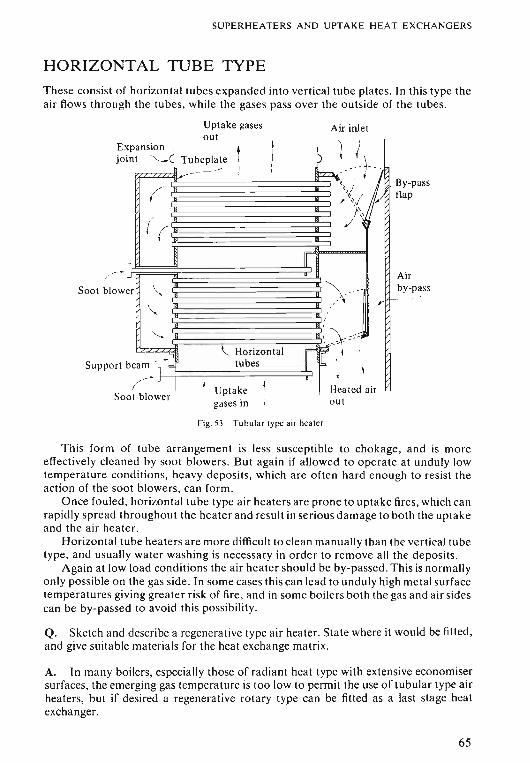
SUPERHEATERS AND UPTAKE HEAT EXCHANGERS
HORIZONTAL TUBE TYPE
These consist of horizontal tubes expanded into vertical tube plates. In this type theair flows through the tubes, while the gases pass over the outside of the tubes.
Airby-pass
By-passflap
Air inlet
outgases in
Uptake gasesout
pansion I 1J/\int ,~ Tubeplate !-
j Ir- -: i( -
/jr:
(( /,
-i II I..J ~
er '\.. ~ ....r -
\"- -"---- ,<, '~ --I~
~ Horizontal r~~--I:s;-
beam ""tubes s'
\('-
I1
;Uptake ~ Heated air
Exjo
Soot blower
Support
Soot blow
Fig. 53 Tubular type air heater
This form of tube arrangement is less susceptible to chokage, and is moreeffectively cleaned by soot blowers. But again if allowed to operate at unduly lowtemperature conditions, heavy deposits, which are often hard enough to resist theaction of the soot blowers, can form.
Once fouled, horizontal tube type air heaters are prone to uptake fires, which canrapidly spread throughout the heater and result in serious damage to both the uptakeand the air heater.
Horizontal tube heaters are more difficult to clean manually than the vertical tubetype, and usually water washing is necessary in order to remove all the deposits.
Again at low load conditions the air heater should be by-passed. This is normallyonly possible on the gas side. In some cases this can lead to unduly high metal surfacetemperatures giving greater risk of fire, and in some boilers both the gas and air sidescan be by-passed to avoid this possibility.
Q. Sketch and describe a regenerative type air heater. State where it would be fitted,and give suitable materials for the heat exchange matrix.
A. In many boilers, especially those of radiant heat type with extensive economisersurfaces, the emerging gas temperature is too low to permit the use of tubular type airheaters, but if desired a regenerative rotary type can be fitted as a last stage heatexchanger.
65
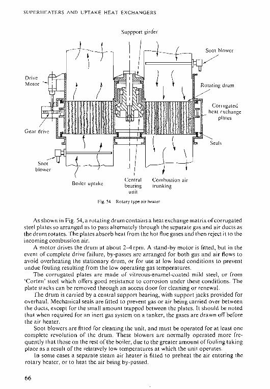
SUPERHEATERS AND UPT A KE HEAT EXCH A NGE RS
Suppport girde r
DriveMotor --
--5001blower
Boiler uptakeCentralbearing
unit
SOO! blower
Corrugated1I(1'l-J!lJl-- heat exc ha nge
plat es
Seal s
Combustion ai rtrunking
Fig.54 Rotary type air heal er
As shown in Fig. 54, a rotating drum contains a heat exchange matrix ofcorrugatedsteel plates so arranged as to pas s alternately through the separate gas and air ducts asthe drum rotates. The plates absorb heat from the hot flue gases and then reject it to theincoming combustion air.
A motor drives the drum at about 2--4rpm. A stand-by motor is fitted, but in theevent of complete drive failure , by-passes are arranged for both gas and air flows toavoid overheating the stationary drum, or for usc at low load conditions to preventundue fouling resulting from the low operating gas temperatures.
Th e corrugated plates are made of vitreous-enamel-coa ted mild steel, or from'Corten' steel which offers good resistance to corrosion under these conditions. Theplate stacks can be removed through an access door for cleaning or renewal.
The drum is carri ed by a central support bearing, with support jacks provided foroverh aul. Mechanical seals are fitted to prevent gas or air being carried over betweenthe ducts, except for the small amount trapped between the plates. It should be notedthat when required for an inert gas system on a tanker, the gases are drawn off beforethe air heater.
Soot blowers are fitted for cleaning the unit, and must be operated for at least onecomplete revolution of the drum. Th ese blowers arc normally operated more frequently that those on the rest of the boiler, due to the greater amount of fouling takingplace as a result of the relatively low temperatures at which the unit operates.
In some cases a separate steam air heater is fitted to preheat the air entering therot ar y heater, or to heat the air being by-passed.
66
CHAPTER 5
Boiler Mountings
Q. Enumerat e the bo iler mountings fitted to a water tub e bo iler. State the purposeof eac h fittin g and a ny special design featu res involved.
A . Various valves and other fitt ings are required for the prop er working of th ebo iler. Those attached directl y to the pressure parts o f the bo iler are referred to asboi ler mount ings. In gene ra l all th ese mountings mu st be carefully designed tope rform their functio n co rrectly. They must be positioned so as to be readilyaccessible both for maintenan ce a nd operati on , the later bein g performed e ithe rdir ec tly, or indirectly, by means of e xtende d rods, spind les, e tc .
for a wat e r tu be boiler th e mountings usuall y co nsist o f the followin g ite ms:
Safety Valves
These are fitted to protect the bo iler from the effec ts of overp ress ure . Th e DOTdem and that at least two safety va lves are fitted to each bo iler, but in pract ice it isusual to fit three sa fe ty valves-two o n the steam d ru m, a nd o ne o n the superhea tero ut let head er. T his latter valve mu st be set to lift before the drum sa fe ty val ves so asto e nsure a flow of stea m th rough the superheat er under blow off conditions. it isnormally of the sa me basic typ e fitted on the drum.
Main Stop Valve
This is mounted o n th e superheat er o utlet head er , and enables the boiler to beisolat ed from the steam line. If two or more boil ers are fitted supp lying ste am to acommon line, the stop valve on each bo iler mu st be a screw down , non-return type .Th is is to prevent steam from the o the r boil ers flowing into a da maged boil er in theeve nt o f a loss of pressu re du e to a burs t tube . In so me cases the main stop va lveinco rpo ra tes a n a uto ma tic clo sin g devi ce , desi gned to operate in e me rge ncy con d itio ns, to shut off stea m fro m the main turbines .
Auxiliary Stop Valves
This is bas ica lly a sma ller versio n of th e main stop, fitted for the purpose of isolatingthe bo iler from the auxiliary steam lines. Again these mu st be screw do wn,non-return type valves if necessary to prevent steam flow ing back into th e boil er inthe eve nt of damage. The va lve will be mounted o n the supe rheater ou tle t head er ; ade- supe rheat er ca n be used to redu ce the stea m temper ature as requ ired .
67
BOILER MOUNTINGS
Feed Check Valves
These are fitted to give final control over the entry of feed water into the boiler. Theymust be screw down, non-return valves so that, in the event of a loss of feed pressure,the boiler water cannot blow back into the feed line.
Main and auxiliary feed checks are fitted. The main check is often fitted to theeconomiser inlet header; if not, like the auxiliary check, it will be mounteddirectly on the steam drum.
Extended sp indles are usually fitted so the checks can be operated from aconvenient position . Care must be taken to ensure the valve can be operated easilyand quickly, and that a positive indication of the open and closed positions for thevalve is given.
Boiler Feed Water Regulator
The water level in a boiler is critical. If it is too low, damage may result fromoverheating; too high and priming can occur with resultant carry-over of water anddissolved solids into superheaters, steam lines, etc.
Automatic feed regulators are therefore fitted to control the flow of water into theboiler and maintain the water level at its desired value.
They are fitted in the feed line, before the main feed check . In most cases they usea float or thermal means of operation and thus must have a direct connection to thesteam and water spaces as required . The regulator can be attached directly to theboiler shell, or alternatively mounted in an external chamber with balance connections to the steam drum, or boiler shell.
In the case of water tube boilers with their high evaporation rate and smallreserve of water the control of the water level is so critical that the classificationsocieties demand that some form of automatic feed regulator must be fitted .
Water Level Indicators
The DOT demand that at least two water level indicators must be fitted to eachboiler. In practice the usual arrangement consists of two direct reading water levelgauges mounted on the steam drum, and a remote reading indicator placed at aconvenient control position.
Low Water Alarms
The classification societies demand that these should be fitted to reduce the risk ofdamage in the event of a loss of water in the boiler due to a burst tube or failure of thefeed supply.
In some cases they are mounted inside the steam drum, but many are mountedexternally . Various types are available, either steam or electrically operated. Someversions also incorporate high water level alarms.
Blow Down Valves
These are fitted to the water drum to enable water to be blown from the boiler inorder to reduce the density. When the boiler is shut down these valves can be used to
68
c..BOILER MOUNTINGS
drain it. They usually consist of two valves mounted in series, arranged so that thefirst valve must be full open before the second can be cracked open; i.e. sufficient togive the required rate of blow down. In this way the seating of the first valve isprotected from damage, so reducing the risk of leakage when the blow down valvesare closed.
These blow down valves discharge into a blow down line leading to a ship-sidedischarge valve.
Scum Valves
These should be fitted when there is a possibility of oil contamination of the boiler.They are mounted on the steam drum, having an internal fitting in the form of ashallow pan situated just below the normal water level, with which to remove oil orscum from the surface of the water in the drum. These valves discharge into the blowdown line.
Drain Valves
These are fitted to headers, etc., so enabling the boiler to be completely drained.They must not be used to blow down when the boiler is steaming under load, only beingopened when the boiler is shut down or in an off load condition.
Air Vents
These are fitted to the upper parts of the boiler as required to release air from drumsand headers, either when filling the boiler, or raising steam.
Superheater Circulating Valves
These are fitted so that when raising steam they can first release air from thesuperheater, and then provide enough circulation to prevent overheating by allowingsufficient steam to blow off to the atmosphere or to a suitable drain system. Theyshould only be closed when there is enough demand for superheated steam to
provide the minimum circulation of steam required to prevent overheating.
Chemical Dosing Valves
These are fitted to the steam drum to enable feed treatment chemicals to be injecteddirectly into the boiler.
Salinometer Valves
These are fitted to the water drum to enable samples of boiler water to be drawn offso that the tests required for the control of the feed treatment can be carried out. Athigh pressures it is necessary to provide some means of preventing flash off takingplace as the pressure over the sample is reduced to atmospheric. This is usually doneby passing the water from the salinometer valve through a cooling coil which reducesits temperature to a value below 100°C.
69
cBOILER MOUNTINGS
Soot Blower Master Steam Valves
These are usually mounted on the superheater outlet header to ensure thesuperheater is not starved of steam while blowing tubes.
In some cases two valves are fitted in series, with a drain valve between them, inorder to prevent steam leaking into the soot blower steam supply lines when these arenot in use .
Pressure Gauge Connections
Fitted as required to steam drum, superheater outlet header, etc . to provide thenecessary pressure readings. In addition suitable connections must be provided forthe pressure sensing points required for automatic combustion control systems, etc.
Thermometers
Pockets must be provided in superhea te r headers, etc . for the fitting of either director remote reading thermometers.
Q. Sketch and describe a water level indicator suitable for boilers operating at lowpressures .
A. Every boiler must have at least two independent means of indicating the waterlevel. These indicators must be placed in a position where they can be easily andclearly seen by the operator. Scotch boilers must have the two indicators placed oneto each side .
Some small, vertical low-pressure boilers may have three test cocks, placedvertically one above the other in way of the normal water level, together with onegauge glass. However no boiler whose working pressure is above 820 kNrrn ", or witha diameter in excess of 1 ·8 m, is a llowed to use test cocks as a means of indicatingwater level.
In most cases marine boilers make use of two indicators in which the water level isclearly visible. For pressures up to 1750 kN/m 2 these usually take the form oftubular-type water level gauges , while for pressures above this value some form ofplate-type gauge glass is used.
The general arrangement of a tubular gauge glass is shown in Fig. 55. It consists oftwo gun-metal bodies, the glass tube fitted between them, being held in place andsealed at each end by nuts tightened onto soft, tapered sealing rings .
Isolating cocks are fitted to the steam and water connections, while a drain cockfitted at the lower end allows for blowing through the glass to test it. In some cases,gun-metal cocks having tapered plugs stemmed with asbestos are used. These are notonly difficult to keep tight, but also are liable to seize up, and in most cases the moreefficient asbestos sleeve-type cocks are used.
The gauge may be fitted directly to the boiler shell, and while this is recommended, in some cases-especially with Scotch boilers-in order to clear the smokebox, etc. it is fitted to an external pipe, or alternatively to a hollow or solid column,the ends of which are then connected to the boiler shell by pipes. Isolating cocks orvalves, fitted where these pipes are attached to the shell, give the advantage of adouble shut off. This enables maintenance to be carried out on the gauge glass cockswhile the boiler is still steaming.
70
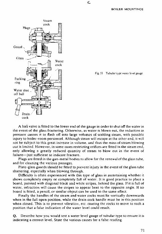
c.BOILER MOUNTINGS
Fig. 55 Tubul ar type water level gauge
A ball valve is fitted to the lower end of the gauge in order to shut off the water inthe event of the glass fracturing. Otherwise, as water is blown out, the reduction inpressure causes it to flash off into large volumes of scalding steam, with possibleinjury to boiler-room personnel. Although steam will escape at the other end , it willnot be subject to this great increase in volume. and thus the mass of steam blowingout is limited. However, in some cases restricting orifices are fitted in the steam end,only allowing a greatLy reduced quantity of steam to blowout in the event offailure-just sufficient to indicate fracture .
Plugs are fitted in the gun-metal bodies to allow for the renewal of the glass tube,and for cleaning the various passages.
Plate-glass guards should be fitted to prevent injury in the event of the glass tubeshattering. especially when blowing through.
Difficulty is often experienced with this type of glass in ascertaining whether itshows completely empty or completely full of water . It is good practice to place aboard, painted with diagonal black and white stripes, behind the glass . If it is full ofwater, refraction will cause the stripes to appear bent to the opposite angle. If noboard is fitted, a pencil, or similar object can be used to the same effect.
Finally the handles of the steam and water cocks must lie vertically downwardswhen in the full open position , while the drain cock handle must be in this positionwhen closed. This is to prevent Vibration , etc . causing the cocks to move to such aposit ion that a false indication of the water level could result .
Q. Describe how you would test a water level gauge of tubular type to ensure it isindicating a correct level. State the various causes for a false reading.
71
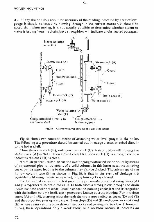
BOILER MOUNTINGS
A. If any doubt exists about the accuracy of the reading indicated by a water levelgauge it should be tested by blowing through in the correct manner. It should benoted that, when testing, it is not usually possible to determine whether steam orwater is issuing from the drain. but a strong blow will indicate unobstructed passages .
Steam isolating r=lvalve (D) ~ U
r · , Guardl/,,I
1'- GlassI
'. Steam cock (A)
Drain cock (C)
Water cock (B)
r -: Guard';,: Hollow column
~I Glass
L .J
( Drain cock (C)
(
Water cock (B)
Water isolating /~valve (E)
Gauge attached directly to ~ge attached to athe boiler shell hollow column
Fig .56 Alternative arrangements of water level gauges
Fig. 56 shows two common means of attaching water level gauges to the boiler.The following test procedure should be carried out on gauge glasses attached directlyto the boiler shell :
Close the water cock (B), and open drain cock (C) . A strong blow will indicate thesteam cock (A) is clear. Then closing cock (A), open cock (B); a strong blow nowindicates the cock (B) is clear.
A similar procedure can be carried out for gauges attached to the boiler by meansof an external pipe, or by means of a solid column. In this latter case, the isolatingcocks on the pipes leading to the column may also be choked. The advantage of thehollow column-type fitting shown in Fig. 56, is that in the event of chokage it ispossible by blowing to determine which of the four cocks is choked.
To do this first carry out the test procedure previously described using cocks (A)and (B) together with drain cock (C). In both cases a strong blow through the drainindicates these cocks are clear. Then to check the isolating cocks (D) and (E) togetherwith the hollow column itself, use a procedure known as cross blowing. For this closecocks (A) and (E), a strong blow through the drain now indicates cocks (D) and (B)and the respective passages are clear. Then close (D) and (B) and open cocks (A) and(E), where again a strong blow shows these cocks and passages to be clear. If howeverduring these operations only a weak blow, or a no blow occurs, it indicates an
72
BOILER MOUNTINGS
obstruction is present in whichever passage is open at the time, and a simple processof elimination will show where the fault lies.
A problem can arise with the hollow column-type fitting in that, if either of theisolating cocks (D) or (E) fitted on the boiler chokes, a strong blow will still beobtained if the gauge glass is tested by means of cocks (A) and (B) only, and noindication of the ob struction will be given . Thus when the gauge glass is returned toservice, if say cock (D) on the boiler is choked , there will be a tendency for the waterlevel in the glass to rise above that in the boiler, due to the vacuum forming in thesteam balance connection to the boiler, causing water to flow into the hollow column.If cock (E) is choked, the water again rises in the glass due to condensation, until suchtime as testing is carried out. Then although a strong blow is obtained, no water willappear in the glass when it is returned to service . Thus the full test procedure,described previously for this type of fitting, should be carried out if any doubt arisesabout the accuracy of the level indicated.
Having checked that all cocks and passages are clear, and with the steam andwater cocks closed, and drain open, a tubular-type water level gauge should be putback into service as follows:
Close the drain, and open water cock (B) very slowly. ff the water level in theboiler is above the passage to this cock, it will enter the glass and rise slowly to thetop. Now open the steam cock (A) , and the correct water level in the boiler will beindicated; this should be between one quarter to three quarters of the glass.
If the level drops from the glass when the steam cock is opened, it indicates thewater level in the boiler lies somewhere between the water passage to the gauge andthe bottom of the glass. In a Scotch boiler the bottom passage lies at least 100 mmabove the top of the combustion chamber; the boiler is still in a safe condition, butfeed water should be added, or the supply increased immediately. On the other handif the water remains at the top of the glass, it indicates too much water in the boiler,and the feed supply should be reduced, or stopped if necessary, to prevent priming.
If no water appears in the glass when the water cock (B) is opened, the level ofwater in the boiler must be below the gauge water passage and the boiler is in apotentially dangerous condition . Reduce boiler load and rate of firing and, as long asthe water covers the combustion chamber tops, the feed supply should be increased,and if necessary the stand-by feed pump and auxiliary feed che ck put into operation.But if the water level does not reappear quickly, or if any doubt exists about the watercovering the combustion chamber tops, take the boiler out of operation. Shut off thefuel and, if it is suspected that overheating has occurred, operate the easing gear onthe safety valves to release the boiler pressure.
When the boiler has cooled down it should be examined, and only returned toservice when considered to be in a safe condition.
Difficulty in deciding whether the glass is completely empty or completely full ofwater, can be avoided by making use of the principles of refraction. A pencil, orsimilar object, held at an angle behind the glass tube will appear to be bent to theopposite angle if the tube is full of water.
A plate-glass guard should be in place around the glass tube to reduce the risk ofinjury during these test procedures.
Q. Enumerate the faults to which direct reading gauge glasses of tubular type aresubject. Explain the effect these faults will have upon the level indicated in the glass.
A. Various reasons can lead to a false reading being indicated by a tubular waterlevel gauge glass. Choked cocks and passages are a common one.
73
BOILER M OUNTI NGS
If the steam cock is choked, a vacuum forms in the upper part of the glass cau singthe wat er to rise until it completely fills the glass.
If the water cock is choked, the water level will rise slowly, conde nsa tio n in thesteam space gradually filling the glass
Simil ar results, although to a lesser extent, can be caused by partially chokedcocks and passages. This chokage is generally brought about by a build-up of depositsleft behind by boiler water evaporating away du e to leakage in way of cocks, etc .
Another reason for ob struction is the cock handle being twisted; so causing theplug to be closed, althougy the handle is in the open position . Thi s can occ ur due totapered plugs, stemmed with asbestos, being nipped up too tight in an attempt to stopthem leaking. This type of fault is unlikely with asbestos sleeve-type cocks, providedre asonable care is taken when inserting a new sleeve. A locating rib on the side of thesleeve en sures correct alignment. Als o ensure the cock handle is co rrect ly atta ched to
the spind le.It should be noted that th e handles on the steam and water cocks should alway s
po int vertically downwards when in the open position as another fault can arise ifthey are left pointing upwards ; i.e. vibr ation cau sing a loose plug to move round to aclosed or partially closed po sition .
The glass tube itself can ca use trou ble. If it is too short it may result in th e packingslee ve being squeezed over the ends of the glass, so block ing the opening. Thi s is mo stlikely to happen at the top ste am end of the glass. Again too lon g a glass projecting upinto the top coc k body can obstruct the steam passage.
A dirty o r salted glass can prevent the water level being easily seen.Where water level gauges are fitted to the boiler indirectly by means of a solid or
hollow column, as shown in Fig. 56, the isolating cock s on the boiler can becomecho ked. Th is again causes the water level in the glass to read too high-for similarreasons to those stated for the steam and water cocks. Additional care mu st be takenwith hollow co lumn- type mountings in that blowing through by me an s of the steamand wat er cocks on the gau ge itself, and not using the isolating cocks on the boiler,will not indi cate if e ither of the latter is choked .
Gauges fitted to the boiler by either of the ab ove methods should be checked on anew boiler, o r afte r a refit , to ensur e that no distortion has taken place or bendsformed in which condensation can coll ect ; these may cau se a possible false reading.
It should also be noted th at the wat er cool s down in the relativ ely long pipesconnecting the columns to the bo iler ; thi s changes its den sity, result ing in a level inthe glass slightly bel ow that in the boil er. Immediately aft er blowing, the level in theglass will appear slightly higher-now correspond ing to th at in the boiler-until thewat er again coo ls down .
The water level gauge should a lways be kept clea n, well lit, and in good order. Allpa ssages and cocks liable to cho kage should be inspected, and cleaned if necessarywhen the boiler is shut down.
Th e water level gauges should be te sted at frequent intervals, and always if anydoubt arises abo ut the accuracy of the water level indicated . Any ob struction mu st becleared as soon as pos sible.
Steam and water cock s and passage s in the gau ge can be cleared wh ile the boiler isstill steaming. To do th is, shut the stea m and water cocks, and ope n th e dra in.Remove th e cleaning plug opposite the obs tru ction. If thi s still cannot be cleared,screw in a plu g with a sma ll hole , about 5 mm diameter , drilled through it in place ofthe cleaning plu g. Insert into thi s hole a rod of such a size that , held by a gloved hand,it ca n be mo ved eas ily without being slack . Then ope n the cho ked cock and pu sh the
74
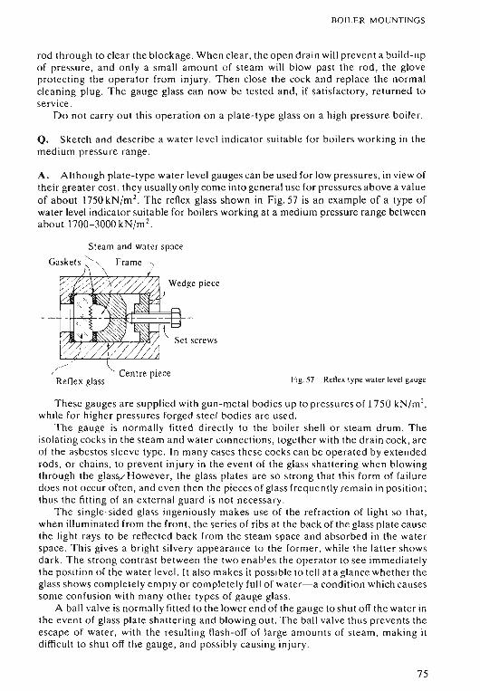
BOILER M OUNTINGS
rod through to clear the blockage. When cle ar , the open dra in will prevent a build-upof pressure , and onl y a sma ll amount of steam will blow past the rod , the gloveprotect ing the operator from injury. Then close the cock and replace th e normalcleaning plug. The gauge glass can now be tested and, if satisfacto ry, returned toservice .
Do not carry out this operation on a plate -type glass on a high pressure boiler.
Q. Sketch and de scribe a water level indicator su itable for boilers working in themedium pressure ra nge .
A. Although plate-type water level gauges can be used for low pressures, in view oftheir greater cost , they usually o nly come into general use for pressures abov e a valueof a bo ut 1750 kN /m 2
. The reflex glass shown in Fig. 57 is an example of a type ofwater level indicator suitable for bo ilers working at a medium pressure range betweena bout 1700-3000kN/m 2
•
St eam and water sp ace"Gaskets ' '\
\
/ / \. , Centre pie ceReflex glass Fig.57 Reflex type water level gau ge
I
These gauges are supplied with gun-metal bodi es up to pre ssures of 1750 kN/m 2,
while for higher pressures forged stee l bodies ar e used .The ga uge is normally fitted directly to the boiler shell o r steam drum. Th e
isolating cocks in the steam and wat er connection s, together with the drain cock , areof the asbestos sleev e type. In many cases these cocks can be operated by ext endedrod s, or chains, to prevent injury in the event of the glass shattering when blowingthrough the glas s> However, the glass plates are so strong that thi s form of failuredo es not occur often , and even then the pieces of glass frequently remain in position ;thu s the fitting of a n extern a l guard is not necessary.
The single-sided glass ingeniou sly makes use of the refraction of light so th at,when illuminated from the front, the series of ribs at the back of th e glass plate cau sethe light rays to be reflected back from the steam sp ace and absorbed in the wat erspace. This gives a bright silvery appea rance to the former. while the latter showsdark . Th e strong contrast between the two e nables the operator to see immediat elythe pos ition of the water level. It also makes it pos sible to tell at a gla nce whether theglass shows completely empty or completely full of water-a condit ion which causessom e co nfusion with many other typ es of gauge glass.
A ball valve is normally fitted to the lower end of the gauge to shut o ff the water inthe event of glass plate sha tte ring and blowing out. The ball valve thu s prevents theescape of water. with the resulting flash-off of large amo unts of s tea m, making itdifficult to shut off the gauge, and possibly causing injury .
75
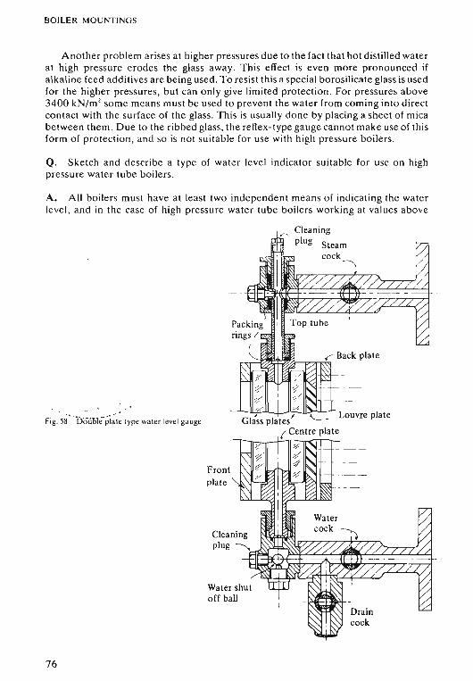
BOILER MOUNTINGS
Another problem arises at higher pressures due to the fact that hot distilled waterat high pressure erodes the glass away. This effect is even more pronounced ifalkaline feed additives are being used. To resist this a special borosilicate glass is usedfor the higher pressures, but can only give limited protection. For pressures above3400 kN/m 2 some means must be used to prevent the water from coming into directcontact with the surface of the glass. This is usually done by placing a sheet of micabetween them . Due to the ribbed glass , the reflex-type gauge cannot make use of thisform of protection , and so is not suitable for use with high pressure boilers.
Q. Sketch and describe a type of water level indicator suitable for use on highpressure water tube boilers .
A. All boilers must have at least two independent means of indic ating the waterlevel, and in the case of high pressure water tube boilers working at values above
Fig. 58' · bii\iOle·pi~ t e type water level gauge
Frontplate
Water shutoff ball
76
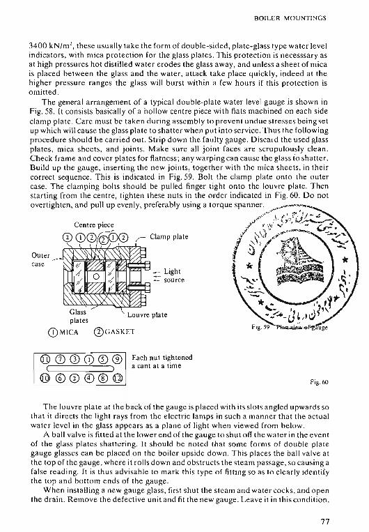
BOILER MOUNTINGS
3400 kN/m l, these usually take the form of double-sided, plate-glass type water level
indicators, with mica protection for the glass plates. This protection is necesssary asat high pressures hot distilled water erodes the glass away, and unless a sheet of micais placed between the glass and the water, attack take place quickly, indeed at thehigher pressure ranges the glass will burst within a few hours if this protection isomitted .
The general arrangement of a typical double-plate water level gauge is shown inFig . 58. It consists basically of a hollow centre piece with flats machined on each sideclamp plate . Care must be taken during assembly to prevent undue stresses being setup which will cause the glass plate to shatter when put into service. Thus the followingprocedure should be carried out. Strip down the faulty gauge. Discard the usedglassplates , mica sheets, and joints. Make sure all joint faces are scrupulously clean.Check frame and cover plates for flatness; any warping can cause the glass io shatter.Build up the gauge, inserting the new joints, together with the mica sheets, in theircorrect sequence. This is indicated in Fig. 59. Bolt the clamp plate onto the outercase. The clamping bolts should be pulled finger tight onto the louvre plate. Thenstarting from the centre, tighten these nuts in the order indicated in Fig. 60 . Do notovertighten, and pull up evenly, preferably using a torque spanner. .,..,--~_M"",
.,...:....» ~ /.' 'F",~r/- '~
Centre piece /" • 1\./;,;·' ·..•V~.; ~"... ~-.
Clamp plate ~ . :--.\t .~,#" ---...'
I; ~\i/t.. l<~\~. ~it ~"t(:~~= '* . ~~ .
::::. Light- source
/W;7A..Ii=....l'"l
Louvre plate
Each nut tighteneda cant at a time
Fig. 60
The louvre plate at the back of the gauge is placed with its slots angled upwards sothat it directs the light rays from the electric lamps in such a manner that the actualwater level in the glass appears as a plane of light when viewed from below.
A ball valve is fitted at the lower end of the gauge to shut off the water in the eventof the glass plates shattering. It should be noted that some forms of double plategauge glasses can be placed on the boiler upside down. This places the ball valve atthe top of the gauge, where it rolls down a nd obstructs the steam passage, so causing afalse reading. It is thus advisable to mark this type of fitting so as to clearly identifythe top and bottom ends of the gauge.
When installing a new gauge glass, first shut the steam and water cocks, and openthe drain. Remove the defective unit and fit the new gauge. Leave it in this condition ,
77
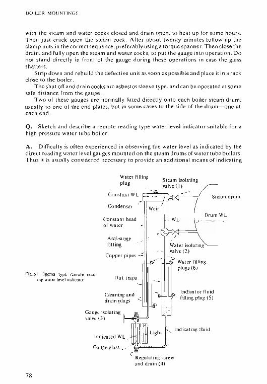
BOI L ER MOUNTING~·
wit h the stea m and wa te r cocks closed and drai n o pe n , to heat up for so me hours.Then ju st crac k o pe n th e stea m cock. After abo ut twenty minutes foll ow up theclamp nuts in the co rrect seq uence, pr ef erably using a torq ue sp a nner. Then clo se th edr a in , and full y open the stea m and wat er cocks, to put th e gauge int o o pera t io n. Donot sta nd direct ly in fron t of th e ga uge du rin g th ese o pe ra tio ns in case the glasssha tters.
Strip down and rebuild th e defect ive unit as so on as pos sible and place it in a rackclose to th e bo iler.
T he shu t off and drain cocks a re asbes to s sleeve typ e , and can be operat ed at som esa fe d is tance fro m th e gauge.
T wo of th ese gauges are normall y fitt ed directl y o nto each boil er stea m drum ,usu all y to o ne o f th e e nd plat es, but in so me cases to th e side of the drum-one a teach e nd .
Q. Ske tc h and describe a remote read ing typ e wa ter level ind icat or sui ta ble fo r ahigh pressure water tube boil e r.
A. Difficult y is ofte n ex perienced in obse rv ing the wa te r level as indicat ed by thedirect readin g wat e r level gau ges mounted on th e ste am dru ms of water tu be boilers.Thus it is usu ally considered necessary to provide an ad d iti onal me ans of indi ca t ing
WL
earn drum
Steam isolatingvalve ( I)
-' 1m
~----nt WL St~
I Inscr Weir
Drumt head WL
~
~
-(Iirge
-- /
Water isolat ing
pipes . .::. -- -. valve (2)
. -r--<;{'" {' Water filling
Iplugs (6)
t traps . .~
'--
g and . -"),~ ~Indicat or fluid
ugs '- filling plug (5)
~. .
II ,e"e'"
U
~ Lighti'- Indicating Iluid
L~
--
Consta
Conde
Dir
Water fillingplug
A nri-sifitt ing
Coppe r
Cleanindrain pi
Cons tanof water
Indica ted W
Gauge glass ____
Gauge isolat ingvalve (3)
Fig. 61 Igerna type remote reading wat er level indica tor
( .Regulatin g screwand drain (4)
78
BOILER M O UNTINGS
the water level at some poi nt convenient to the start ing plat form or control room .This can be done by a remote reading indicator suc h as the (Igema) ga uge show nin Fig.61.
This consi sts basically of a U- tube, the two legs con nec ted to the stea m drum asshown. Red indi cat ing fluid , which is insolub le in wa ter, fills the lower end andrem ain s there since its density is grea te r th an th at of the water.
A bove this fluid the two legs of the U-tube are filled with wat er ; one being keptfilled to a co nsta nt head by mean s of steam conde nsing in the unlagged conden ser.T he level in the other leg co rres po nds to that in th e steam drum. Thus the head ssupported by th e indica ting fluid vary . As the wate r level in th e drum rises so it tendsto ba lance the constant head, and the indicating fluid rises in th e glass . The opposit ehappen s when the drum wate r level falls, the level of th e ind ica ting fluid in the glassalso falling.
The sharp contrast bet ween th e red indicating fluid and the water enables theope ra tor to see the indi cated wat er level at a glance . A complete ly empty o r full glassis imme diately obvi ou s.
Wh en taking the boiler ou t of se rvice , shut off the rem ot e indicato r by first closi ngthe gauge iso lating valve (3) , then the steam isolating valve (1), an d finally the waterisolating valve (2) .
When ope ning up , first open the stea m valve (1 ), then the wat er valve (2), andfina lly th e ga uge isolatin g va lve (3) .
If the remote indi cator is connec ted to the same balance connection s as one of thedirec t reading water level gauges , it is important that th e rem ot e indica to r is isolatedbefore th e water level gau ge is blow n through . Otherwise water may be drawn out ofthe legs of the U-tube so caus ing a false wate r level to be ind icat ed by th e rem ot ereadin g ga uge.
Afte r cleaning, etc. the following procedur e sho uld be carried out to refill theind icat or. First close the isolat ing valves ( 1) and (2) on the bo iler , and th e regul at ingscrew (4) . Rem ove all filling plu gs. Th en pour in the indi cat ing fluid through theindica tor filling plug (5) until the lower part of the U-tube is complete ly filled, fluidove rflowing at the filling plu g.
Close the gauge isolat ing valve (3) and replace the filling plug (5) . Then slowlypo ur d istilled water into the wate r filling plugs (6) on top of the di rt tr aps until itove rflows. Replace the filling plu gs. Fin ally pour water into th e top filling plug (7),unt il aga in it overflows; the plug is th en replaced.
The re mo te reading gauge glass sho uld now show complet ely red . Leave it in th iscon diti on until full boiler pre ssur e has been raised .
Wh en th e boiler is under steam ope n the stea m valve (1), then the wat er va lve (2)followed by th e ga uge isolating va lve (3) . Leave for ab out 15 minutes to se tt le down ,then crack ope n the regulating screw (4) and slowly bleed off excess indica ting fluid,d ropp ing the level ab out 6 mm at a time , with abo ut fifteen minutes betw een , untilfina lly the level of indi cating fluid at th e centre of the glass co rrespo nds to th e waterlevel a t th e ce ntre of the dir ect read ing wat er level gauge glass.
Althou gh subje cted to boiler pressur e, th e remote indicator glass is not at hightem per ature and very rarely gives trouble . However, the appar at us .should beclean ed out about once every six months. Th e indicato r should be isolated , dra ined,and th e flushed through with clean wat er. Th e indicator mu st neve r under anycircumstan ces be blown through either with steam or water.
Th e glass is illuminated from behind , access to these light s bein g o btai ned byremoving the sheet met al casing at the back of the gauge.
79
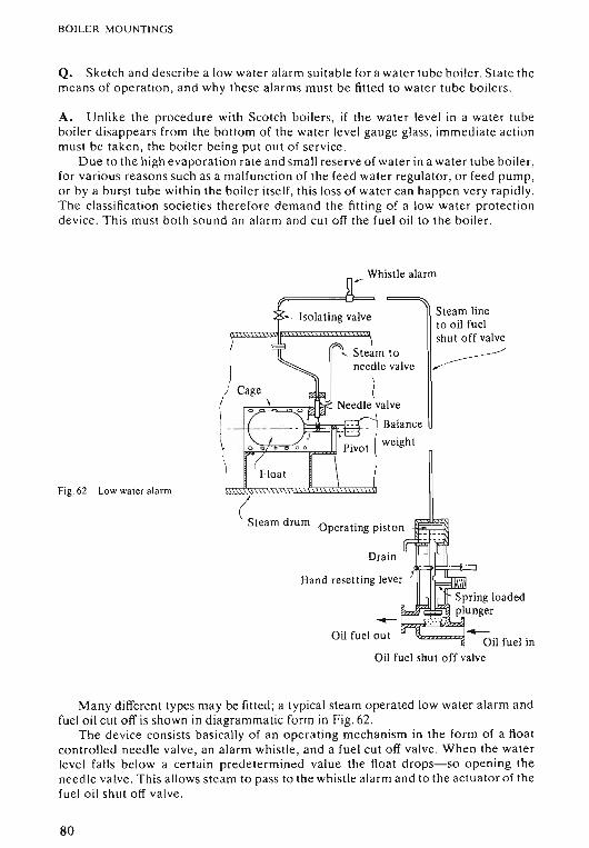
BOILER M O UNTINGS
Q. Sketch and de scr ibe a low water a larm suitab le for a wat er tube boil e r. St at e themean s of o peratio n, a nd wh y these alarms mu st be fitted to water tube boilers .
A. Unlike the procedure with Scotch boilers, if the water level in a wa te r tubeboiler dis appears from the bottom of th e wat er level ga uge glass, imm ed iat e actionmu st be tak en , the boil er being put out o f se rvice.
Du e to th e high eva po ra tio n rat e and sma ll reserve of wat er in a water tub e boiler,for various reasons su ch as a malfunct ion of the feed water regul at or, or feed pump,o r by a burst tube within the boiler itself , this loss of water can happen ve ry ra pid ly.Th e classificati on societies therefore dem and the fitting of a low wa te r pr ot ect ionde vice. Thi s must both so und a n a larm and cut off the fuel oil to the boil er .
Whistle alarm..-
Steam lineto oil fuelshut off valve
,~
..'Q",,=91 Oil fuel in
Oil fuel shut off valve
Oil fuel out
Hand resett ing lever
Drain
Isolating valve
(Steam drum Operating piston
Fig. 62 Low water a larm
Man y different types may be fitted ; a typical stea m operated low wa ter ala rm a ndfuel oi l cut off is sho wn in dia grammat ic form in Fig. 62.
The de vice co nsists ba sicall y of an o pe ra ting mechani sm in the for m of a floatcontrolled needle va lve , an alarm whistle, and a fuel cut o ff valve . Wh en the waterlevel fa lls below a certain predet ermined value the float drops-so ope ning theneedl e valve. This allows steam to pass to th e whi stle alarm and to the ac tuato r of thefuel o il shut o ff va lve .
80
BOILER MOUNTINGS
When the steam pressure acts on the actuator piston it pushes it downwards, soclosing the shut off valve. When the valve closes, a spring loaded plunger moves into aslot in the valve spindle , and holds the valve in the closed position until it can be resetby hand . This is to prevent some transient event, such as the water surging in thedrum due to heavy weather conditions, causing the fuel oil shut off valve to first closeand extinguish the furnace flame. If this valve were then allowed to reopenautomatically immediately the water level is re-established, it could result in largequantities of unburnt oil being sprayed into the hot furnace leading to a possible gasside explosion causing damage or starting an uptake fire.
In addition to this resetting device, an anti-surge device will be fitted to theoperating mechanism . In the type being considered it takes the form of a cage placedaround the float. Holes in this cage are such that if, during heavy weather, the waterlevel drops momentarily below the minimum level allowed, it will have surged backbefore the water in the cage has time to drain out enough to operate the mechanism.
Another refinement which may be fitted is the internal steam supply pipe. Thisprevents deposits forming around the needle valve seat in the event of leakage, i.e. asmight occur if the chamber were left open to the boiler water.
In many versions the operating mechanism is mounted in an external chamber,and connected to the drum by steam and water balance connections . This gives theadvantage that maintenance can be carried out on the operating mechanism withoutshutting down the boiler.
The low water alarm should be tested at frequent intervals, and as soon aspracticable after any work or adjustments have been carried out on it. If for anyreason the device has to be shut off a notice should be displayed on the startingplatform, or in the control room , informing the watch-keeping Engineers of the fact.The device should be returned to service as soon as possible .
Q. Sketch and describe an electrically operated low/high water level alarm andcut-out.
A. The type illustrated in Fig . 63 operates on the principle that while unlike magneticpoles attract each other, like poles are repulsed.
An external float chamber with balance connections to the steam drum is mountedin way of the drum water level. A float within the chamber then relates to this waterlevel, and moves an attached magnet up and down in response to any changes of waterlevel within the steam drum.
Four micro switches with magnetically operated arms are fitted on the outside ofthe balance chamber. They are arranged so that, when the internal magnet comes levelwith one of these external magnets, like poles are presented, and so, repelling eachother, operate the micro switch .
The positions of the four switches are set to correspond to predetermined waterlevels within the steam drum. One switch will correspond to a low water level condition, and when this is reached will operate an alarm. If then no corrective action istaken, or it proves ineffective , and water level continues to fall, the next switch positioned to a predetermined low low water level will trip out the fuel oil shut-off valve, soshutting the boiler down before damage can occur.
The other two switches are positioned in a similar manner for high water levels,operating an alarm for a predetermined high water level in the drum, tripping out thefuel oil shut-off valve, and closing in a motorised feed check valve in the event ofa highhigh water level.
81
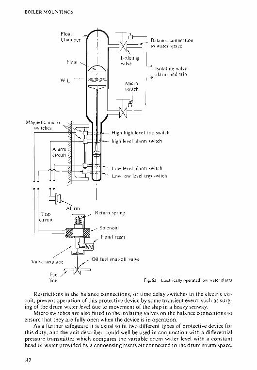
BOllER MOUN TI NGS
Low level alarm switch
Low low level trip switch
High high level trip switch
high level alarm switch
Balance connectionto water space
Isolatingvalve
lsol at ing va lve
Micro r alarm a nd trip
S~ICh I
Floal
FloatC ha mbe r
W. L. '-
Magnetic microswitches
AlarmTrip
circuit
/
Valve actuat or
Return spring
Fig.63 Electrically operated lowwater alarm
Restrictions in the balance connections, o r time delay switches in the electri c circuit, p revent ope rat ion of th is pr otect ive device by some transient eve nt, such as surging of the drum water level d ue to movement of the ship in a heavy seaway.
Micro switches are also fitted to the isolating valves on the balan ce connection s toensure that they are fully open when the device is in operation.
As a further safeg ua rd it is usual to fit two different types of protective device forth is duty, and the unit described could well be used in conjunction with a differenti alpressur e transmitter which compares the variable drum water level with a consta nthead of wat er provided by a condensing reservoir connected to the drum steam spa ce.
82
BOILER MOUNT INGS
Movement of the transmitter is amplified and used to operate fo ur micro switc hes in asimila r man ner to the magnet ic type, as the water level moves th rou gh its full ra nge.
Th ese devices sho uld be tested by act ua lly raising or lower ing the drum water levelwhen the boi ler is off load , the direct-read ing water level gauges bein g observedthro ugho ut the test to ensure co rrect operation o f the devices. Eac h device is gagged inturn, to make sure that each individual unit is functioning prop erly. It shoul d be notedthat different ial pressure devices a re sensitive to water density and sho uld only betested with the boi ler at full working pressure.
Q. Sketch and describe an Improved high lift type safety va lve.
A. This is a sa fe ty device fitted to the boiler to prevent overpressure . Th e DOTdem and a min imum of two sa fety va lves to each boiler , and a ltho ugh these may befitted in the same valve chest with a single connec tion to the boi ler, the sa fety valvesmust be ca pable of releasing the maximum amo unt of ste am th e boiler can evaporate ,while still keep ing within th e 10 pe r cent accumulation of pressure rule.
This rule is necessary be cause , having ca lculated the cross sec tio nal area for th eva lve bore , the valve lid mu st be ab le to lift a t least 1of th e va lve bor e in or de r toprovide full stea m flow. However as the valve lifts, the for ce to compress th e springalso inc reases, and so the highe r the valve lifts the greater the increase in boi lerpressur e . Th e DOT limit th is accumulation of pressure to 10 per cent of themaximum allow abl e working pressure for the boile r. This mean s th at the lift o f anordi na ry spring-loaded mitre va lve, although mechanicall y able to lift 1D , would bevery limited unde r these conditions, and the valve wo uld ha ve to be very large to givethe requ ired throu ghput.
Va rious designs have been developed to increase thi s wor king lift, an d theImprov ed high lift sa fety valve is a very suitable one for low and medium pressu reboilers. See Fig .64.
T hese valves increase thei r lift ove r that of a simple spring- loaded mitre va lue intwo ways: See Fig. 65.
O ne is the specia lly sha ped valve sea t, the o ther being to use th e lower springca rrier in th e fash ion of a piston , which ac ted up on by the pressure of the waste steamhel ps to compress the spring.
As can be seen in Fig. 65, a lip is placed around the va lve sea t so tha t, when thevalve lid lifts, escap ing stea m is trap ped in the annular space around the valve face ;the resultant buil d-up of pr essure ac ting upon the grea te r va lve lid area cau ses th evalve to lift sha rply. This ar ra nge me nt gives ano ther advantage in th at if the valvewere a llowed to close slowly, the final film of ste am blowing ac ross th e faces set s uphigh frictional resistan ce to the closu re of the valve , and this can cause the boile rpressure to fall well be low the blow off pre ssure befor e the valve fina lly clos es . This isreferred to as the blow do wn effect , and can ca use conside ra ble wastage of stea m.Th e shape d valve seat causes the va lve lid to pulsat e , and thi s 'Di rling' action ena blesthe va lve to close cleanly and sharply with ver y littl e blow down effect.
T he second feature of th e valve lies in the fact that as the escap ing steam enter sthe was te pipe and, altho ugh regulati ons exist to prevent this pip e be ing mad e toosmall , so me build-up of pressure does take place . Th e Imp roved high lift sa fety valvemak es use of thi s waste press ure to increase the va lve lift. Th is is do ne as pr eviou slyment ion ed by allowi ng th is pressu re to ac t upon the lower spring ca rrie r, which fits
83
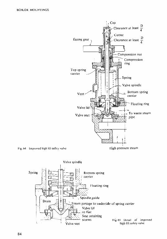
BOILER M OU NTING S
DClearan ce at least 4
D
4
Top springcarr ier
_ Spr ing
Valve spindle
Bottom springcarrier
Fig.64 Imp ro ved high lif! safety valve High pressur e steam
Valve spindle
Floating ring
Bottom spring( carrier,
_Spindle guide
' Steam passage to underside of spring carrier, Valve lid
'-1,1{:: JA I/)\"+,,,, ~ ' or disc
, ,-~. ' Seat retaining. r-::':::~':::==I:=¢:=':£~~ screws Fig. 65 De tail o f improved
high lift sa fely valve
,'.Spring .
84
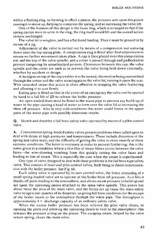
BOILER MOUNTINGS
within a floating ring, so forming in effect a piston; the pressure acts upon this pistoncausing it to move up, helping to compress the spring, and so increasing the valve lift.
One of the features of this design is the loose ring, which is arranged so that if thespring carrier were to seize in the ring, the ring itself would lift and the overall actionremain unchanged.
The valve lid is wingless, and has a flat faced landing. Thus it must be ground in bymeans of a jig.
Adjustment of the valve is carried out by means of a compression nut screwingdown onto the top spring plate. A compression ring is fitted after final adjustment toensure no further movement takes place. A cap is then placed over this compressionnut and the top of the valve spindle, and a cotter is passed through and padlocked toprevent tampering by unauthorized persons. Clearances between this cap, the valvespindle and the cotter are such as to prevent the valve being held down externally,whether by accident or design.
A hexagon on top of the cap enables it to be turned, this motion being transmittedthrough the cotter and the valve securing pin to the valve lid, turning it upon the seat.With saturated steam this action is often effective in stopping the valve featheringand allowing it to seat firmly.
Easing gear is fitted so that in the event of an emergency the valve can be openedby hand to a full lift of !D to release the boiler pressure.
An open-ended drain must be fitted to the waste pipe to prevent any build-up ofwater in the pipe causing a head of water to form over the valve lid so increasing theblow off pressure. Also in very cold conditions this water could freeze in the upperparts of the waste pipe with possibly disastrous results.
Q. Sketch and describe a full bore safety valve operated by means of a pilot controlvalve.
A. Conventional spring-loaded safety valves present problems when called upon todeal with steam at high pressures and temperatures. These include distortion of thespring and valve seats, and the difficulty of getting the valve to close smartly at theseextreme conditions. The latter is necessary in order to prevent feathering; this is thename given to a condition where a thin film of steam blows across between the valvefaces-the wire-drawing resulting from this quickly cutting the valve faces andleading to loss of steam. This is especially the case when the steam is superheated.
One type of valve designed to deal with these problems is the full bore type safetyvalve. This consists of main and pilot control valves, both being in direct communication with the boiler pressure. See Fig. 66.
Each safety valve is operated by its own control valve, the latter consisting of asmall spring-loaded valve set to operate at the boiler blow off pressure. As it lifts itblanks off ports leading to the atmosphere, and allows steam pressure to build up andact upon the operating piston attached to the main valve spindle. This piston hasabout twice the area of the main valve, and the forces set up cause the main safetyvalve to open one-quarter of its diameter, so giving full bore conditions for the escapeof the boiler steam to the atmosphere through the waste pipe. The throughput isapproximately 4 x discharge capacity of an ordinary safety valve.
When the excess boiler pressure has been relieved the pilot valve closes, soopening the ports and allowing the operating steam to vent to the atmosphere; thisreleases the pressure acting on the piston. The escaping steam, helped by the valvereturn spring, closes the main valve.
85
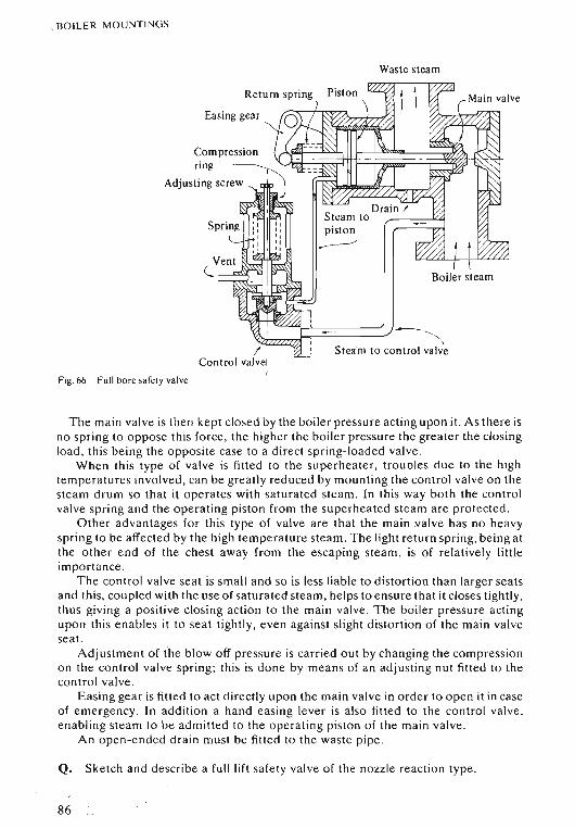
, BOI LER MOUNTINGS
Wastesteam
Easinggear
Compressionri ng '-..)"""-"""",,M
Adjusting screw I~
I
I
Boiler steam
~=~i'--------' -"--\Steam to control valve
Fig. 66 Full bore safely valve
The main valve is then kept closed by the boiler pressure acting upon it. As there isno spring to oppose this force, the higher the boiler pressure the greater the closingload, this being the opposite case to a direct spring-loaded valve .
When this type of valve is fitted to the superheater, troubles due to the hightemperatures involved, can be greatly reduced by mounting the control valve on thesteam drum so that it operates with saturated steam. In this way both the controlvalve spring and the operating piston from the superheated steam are protected.
Other advantages for this type of valve are that the main valve has no heavyspring to be affected by the high temperature steam. The light return spring, being atthe other end of the chest away from the escaping steam, is of relatively littleimportance.
The control valve seat is small and so is less liable to distortion than larger seatsand this, coupled with the use of saturated steam, helps to ensure that it closes tightly,thus giving a positive closing action to the main valve. The boiler pressure actingupon this enables it to seat tightly, even against slight distortion of the main valveseat.
Adjustment of the blow off pressure is carried out by changing the compressionon the control valve spring; this is done by means of an adjusting nut fitted to thecontrol valve .
Easing gear is fitted to act directly upon the main valve in order to open it in caseof emergency. In addition a hand casing lever is also fitted to the control valve,enabling steam to be admitted to the operating piston of the main valve.
An open-ended drain must be fitted to the waste pipe .
Q. Sketch and describe a full lift safety valve of the nozzle reaction type.
86
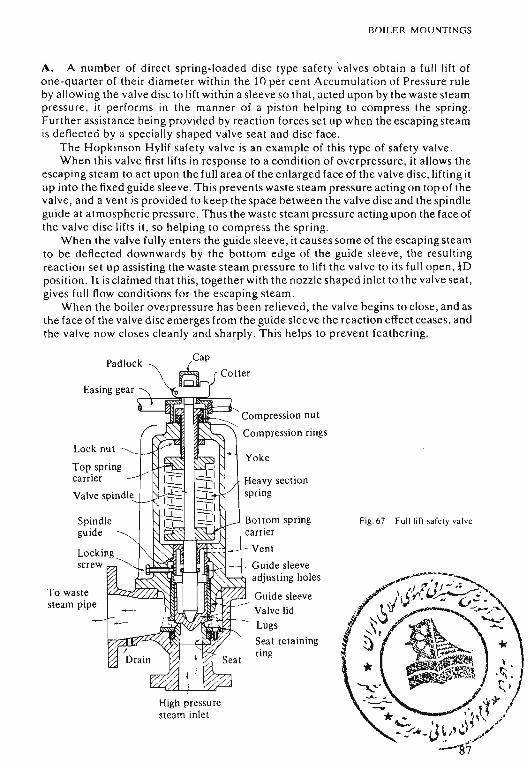
BOILER MOUNTINGS
A. A number of direct spring-loaded disc type safety valves obtain a full lift ofone-qua rte r of their diameter within the 10 per cent Accumulation of Pressure ruleby allowing the valve disc to lift with in a sleeve so that , acted upon by the waste steampre ssure, it performs in the manner of a piston helping to compress the spring.Further assistance being provided by re action forces set up when the escaping ste amis deflected by a specially shaped valve scat and disc face.
The Hopkinson Hylif safety valve is an example of this type of safety valve .When this valve first lifts in response to a condition of overpressure, it allow s the
escaping steam to act upon the full area of the enlarged face of the valve disc, lifting itup into the fixed guide sleeve. This prevents waste steam pressure acting on top of thevalve, and a vent is provided to keep the space between the valve disc and the spindleguide at atmospheric pressure. Thus the waste steam pressure acting upon the face ofthe valve disc lifts it, so helping to compress the spring.
When the valve fully enters the guide sleeve , it cau ses some of the escaping steamto be deflected downwards by the bottom edge of the guide sleeve , the resultingreaction set up assisting the waste steam pre ssure to lift the valve to its full open.Tl)position . It is claimed that this, together with the nozzle shaped inlet to the valve seat ,gives full flow conditions for the escaping steam .
When the boiler overpressure has been relieved , the valve begins to close, and asthe face of the valve disc emerges from the guide sleeve the reaction effect ceases, andthe valve now closes cleanly and sharply. Th is helps to prevent feathering.
Padlock
Lock nut
Top springcarrier
Valve spindle
Spindleguide
To wastesteam pipe
Compression nut
Compression rings
Fig. 67 Fulilirt safely valve
- Vent
Guide sleeveadjusting holes
Guide sleeve~.,o-v,.l--_-_- Valve lid
~ Lugs
Seat retainingring
I
High pre ssuresteam inlet
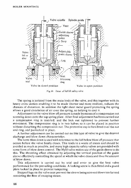
BOILER MOUNTINGS
-:..J Valvespindle
Valve in closed position Valve in open position
Fig.68 Detail of full lift safety valve
The spring is isolated from the main body of the valve, and this together with itsheavy cross section enabling it to be made shorter and more resilient, reduces thechances of distortion. In addition the light sheet metal guard protecting the springallows a good circulation of air over the spring, so helping to cool it.
Adjustment to the valve blow off pressure is made by means of a compression nutscrewing down onto the top spring plate. After final adjustment has been carried outa compression ring is inserted, and the lock nut tightened to prevent furthermovement. The compression ring is in two halves so it can be placed in positionwithout disturbing the compression nut . The protective cap is then fitted over the nutand ring, and padlocked in place .
A further adjustment can be carried out on this type of valve to give the desireddischarge and blow down characteristics .
The term blow down is used with reference to the fall below blow off pressure thatoccurs before the valve finally closes. This leads to a waste of steam and should beavoided as much as possible , and many high capacity safety valves are provided withsome form of blow down control. The Hylif valve makes use of the guide sleeve to dothis . The throttling effect obtained by adjusting the vertical position of the guidesleeve effectively controlling the speed at which the valve closes and thus the amountof blow down.
This adjustment is carried out by trial and error to give the best valveperformance for the prevailing conditions. A locking screw is then fitted and a guardplate locked in place to prevent tampering.
Stepped lugs on the valve seat prevent the sleeve being screwed down too far andrestricting the flow of escaping steam.
88
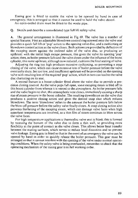
BOILER MOUNTINGS
Easing gear is fitted to enable the valve to be opened by hand in case ofemergency; this is arranged so that it cannot be used to hold the valve closed .
An open-ended drain must be fitted to the waste pipe.
Q. Sketch and describe a consolidated type full lift safety valve.
A. The general arrangement is illustrated in Fig. 69. The valve has a number ofspecial features . First an adjustable blowdown control ring screwed onto the valve seatprovides a quick full lift or 'pop' action to the opening valve disc, and a cushioning orblowdown control action as the valve closes. Both actions are provided by deflection ofthe escaping steam against the inclined sides of the valve disc, so producing anupthrust: with the initial high escape pressure, this gives the valve its opening 'pop'action; then, as boiler pressure falls and the valve closes under the influence of the boostcylinder, this same upthrust, although now reduced, cushions the final seating ofvalve.
Adjusting the ring too high produces excessive cushioning, so preventing a snapclosing of the valve, which can cause excessive loss ofboiler pressure before the valveeventually shuts. Set too low, and insufficient upthrust will be provided on the openingvalve with resulting loss of the required 'pop' action, which in turn can lead to the valvedisc chattering on its seat.
A second feature is a boost cylinder fitted above the valve disc to provide a precision closing control. As the valve pops full open, some escaping steam is bled off tothis boost cylinder from whence it is vented to the atmosphere. As boiler pressure fallsand the valve begins to shut, this atmospheric vent closes, immediately causing a sharprise of steam pressure in the boost cylinder. The resulting down thrust on the valve discproduces a positive closing action and gives the desired snap shut which reducesblowdown. The term 'blowdowri' refers to the amount the boiler pressure falls belowthe blow-off pressure before the safety valve finally closes . A snap closing action "alsoprevents feathering of the escaping steam, which can damage valve faces when highsuperheat temperatures are involved, as a thin film of steam continues to blow acrossthe valve faces.
For high temperature applications a thermodisc valve seat is fitted; this is formedby recessing the bottom of the valve disc to form a thin wall, so providing extraflexibility at the point of contact as the valve closes. This allows better heat transferbetween the mating surfaces, which serves to reduce local distortion and so preventvalve leakage. Easing gear is fitted so that in the event ofan emergency the valve can beopened by hand in order to quickly release the boiler pressure. This gear must bearranged so that it cannot interfere with the opening of the valve under normal operating conditions. When the safety valve is being overhauled, remember to check that theoperating mechanism of the easing gear is in full working order.
89
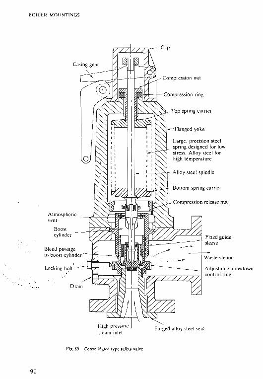
BOILER MOUNTINGS
Atmosphericvent
Boostcylinder
Bleed passageto boost cylinder ---r-j------~
Drain
Ca p
Co mpression nut
"'I~i)1l-loA----i- Co mpressio n ring
Top spring carrier
- Flanged yoke
Large, prec ision steelspring designed for lowstress. Alloy stee l forhigh lemperature
I--'l---,---i«->""t- Alloy stee l spindle
Bott om spring ca rrier
Co mpression release nut
Fixed guidesleeve
Waste steam
Adjustable blowdowncontrol ring
Forged alloy stee l sea t
90
Fig .6 9 Consolida ted type safety valve
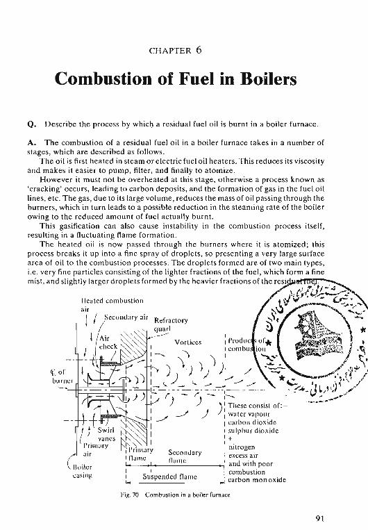
CHAPTER 6
Combustion of Fuel in Boilers
Q. Describe the process by which a residual fuel oil is burnt in a boiler furn ace.
l lcat cd comb ust ion
Cl orburner
'--0. I f---'--------'--11 '
III,
Refractoryquarl_..-----
V ort ices
Secon daryI, [lu mcI
Suspend ed name
II l'roducI com bu.
Fig.70 Combustion in a boiler furnace
91
COMBUSTION OF FUEL IN BOILERS
The burner also imparts rotational energy to the fuel so that it leaves the burnertip as a hollow, rotating cone formed of fine droplets of oil.
The combustion stage itself can now commence, and in a boiler furnace a type ofcombustion often referred to as a 'suspended flame' is used . For this a stream of oilparticles and air enters the combustion zone at the same rate at which the products ofcombustion leave it. The actual flame front therefore remains stationary, while theparticles pass through it, undergoing the combustion process as they do so. Thecombustion zone itself can be sub-divided into two main stages; these are referred toas the primary and secondary flames.
PRIMARY FLAMEFor the oil to burn, it must be raised to its ignition temperature, where continuousvaporization of the oil required for its combustion takes place. Note this temperatureshould not be confused with the flash point temperature of the oil, where only thevapour formed above the oil in storage tanks, etc. will burn. The ignition or burningtemperature should normally be at least some 20°C above this value.
For the reasons already stated this ignition temperature cannot be obtained in thefuel oil heaters, and therefore the heat radiated from the flame itself is utilized sothat, as the cone of atomized oil leaves the burner, the lighter hydrocarbons arerapidly raised to the required temperature by the heat from the furnace flame; theythen vaporize and burn to form the primary flame.
The heat from this primary flame is now used to heat the heavier constituents ofthe fuel to their ignition temperature as they, together with the incoming secondarycombustion air, pass through the flame.
The stability of the combustion process in the furnace largely depends uponmaintaining a stable primary flame and, to ensure it is not overcooled, a refractoryquarl is usually placed around it so as to radiate heat back to the flame . The primaryflame should just fill the quarl . If there is too much clearance excessive amounts ofrelatively cool secondary air enter the furnace; too little and the heavier oil dropletsimpinge on the quarl and form carbon deposits.
Another important factor for the formation of the primary flame is that it must besupplied with primary air in the correct proportion and at the right velocity. In thecase of air registers using high velocity air streams this is done by fitting a tip platewhich spills the primary air over into a series of vortices, as indicated in Fig. 70. Thisensures good mixing of the air and fuel and, by reducing the forward speeds involved,helps to maintain the primary flame within the refractory quarl.
SECONDARY FLAME
The larger oil droplets, heated in their passage through the primary flame zone, thenvaporize and begin to burn. This, although a rapid process, is not instantaneous, andso it is essential that oxygen is supplied steadily and arranged to mix thoroughly withthe burning particles of oil. An essential feature for the stability of this suspendedsecondary flame is that the forward velocity of the air and oil particles must notexceed the speed of flame propagation. If it does the flame front moves further outinto the furnace and the primary flame will now burn outside the quarl with resultinginstability due to overcooling.
92
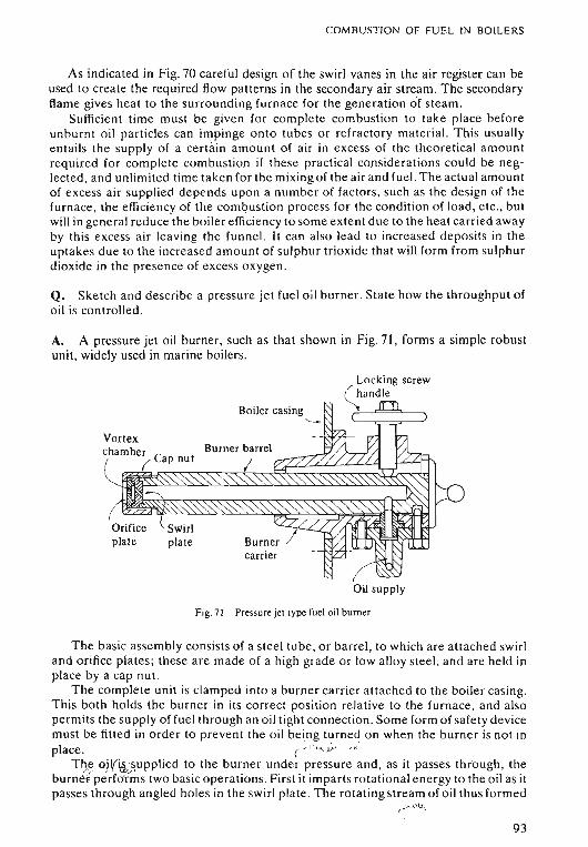
COMBUSTION OF FUEL IN BOILERS
As indicated in Fig. 70 careful design of the swirl vanes in the air register can beused to create the required flow patterns in the secondary air stream. The secondaryflame gives heat to the surrounding furn ace for the generation of ste am.
Sufficient time must be given for complete combustion to take place beforeunburnt oil particles can impinge onto tubes or refractory mat erial. This usu allyentails the supply of a certain amount of air in excess of the theoretical amountrequired for complete combustion if the se practical considerations could be neglected , and unlimited time taken for the mixing of the air and fuel. The actual amountof excess air supplied depends upon a number of factors, such as the design of thefurnace, the efficiency of the combustion process for the condition of load, etc., butwill in general reduce the boiler efficiency to some extent due to the heat carri ed awayby this excess air leaving the funn el. It can also lead to increased deposits in theuptakes due to the increased am ount of sulphur trioxide that will form from sulphurdioxide in the pre sence of excess oxygen .
Q. Sketch and describe a pressure jet fuel oil burner. State how the throughput ofoil is controlled .
A. A pressure jet oil burner, such as that shown in Fig . 71, forms a simple robustunit, widely used in marine boilers.
Boiler casing'--
carrier
/' Locking screw~and le
Oil supply
Fig. 71 Pressure jet type fuel oil burner
The basic assembly consists of a steel tube, or barrel, to which are att ached swirland orifice plates; the se are made of a high grade or low alloy ste el, and are held inplace by a cap nut.
The complete unit is clamped into a burner carrier attach ed to the bo iler cas ing.This both holds the burner in its correct position relative to the furnace , and alsopermits the supply of fuel through an oil tight connection. Som e form of safety dev icemust be fitted in order to prevent the oil being turned on when the burner is not inplace. ( ~' l · l' . ';" . .'Yo '
Try.e oWi&,~~upplied to the burner under pressure and , as it pass es through, theburnet performs two basic operations. Fir st it imparts rot ational energy to the oil as itpasses through angl ed holes in the swirl plate . The rotating stream of oil thus form ed
r--"Jt' ~
93
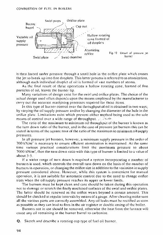
COMBUSTION OF FUEL IN BOILER S
Swirl plate __/ Swirl chamber
Atomizingorifice
Swirl ports
Detai l of pressure jetburne r
Fig. 72
Hollow rotatingcone formed ofoil droplets
Orifice plate
«: Cap nutrT""O,....,,--r'-;,..--,r/""-;""7I-ri7J
Burnerbarrel
Variable oilsupplypressure
is then forced under pressure through a sma ll hole in the orifice plat e whi ch ca usesthe jet to break up into fine droplets. This latter process is referred to as ato mization,a ltho ugh ea ch indi vidual droplet of oil is formed of vast numbers of ato ms .
As the final result of these operations a hollow rotating cone, formed of fineparticles of oil , lea ves the burner tip.
Many variations o f design exist for the swirl and orifice plates. The choice of theactual design used often depends upon the means employed by the manufacturer tocarry out the accurate machining processes required for these items .
In thi s type of burner control over the throughput of oil is obtained in two ways ;by varying the oil supply pressure and/or by changing the diameter of the hole in theorifice plate . Limitations exist which prevent either method being used as the so lemeans of control over a wide range of throughput. ..r. ,·",,tr>
The rat io of the maximum to minimum oil throughput of the burner is known asthe turn down ratio of the burner, and in the case of pressure jet burners this can besta ted in terms of the square root of the ratio of the maximum to minimum oil supplypressures .
In all pressure jet burners, however, a minimum supply pressure in th e order of700 kN/m 1 is necessary to ensure efficient atomization is maintained. At the sam etime various practical considerations limit the maximum pressure to abo ut7000 kN/m 1
, thus the turn down ratio with this type of burner is limited to a value ofabout 3·5 .
If a wider range of turn down is required a system incorporating a number ofburners is used, which controls the overall turn down on the basis of the number ofburners in operation, or changing the orifice size in addition to the variation in supplypressure con sidered above . However, while this system is convenient for manualoperation, it is not suitable for automatic control due to the need to change orificesizes when the oil supply pressure reaches its upper or lower limits.
The burners must be kept clean and care should be taken during this operationnot to dam age o r scra tch the finely machined surfaces of the swirl and orifice plates .The latter sho uld be renewed as the orifice wears beyond a certain amount. Thissho uld be check ed at regular intervals by means of a gauge. After cleaning make sureall the various parts are correctly assembled. Any oil leaks must be rectified as soo nas po ssible as they can lead to fires in the air register or double casing of the boil er.
Burners not in use sho uld be removed, otherwise the heat from the furnace willcause any oil rem aining in th e burner barrel to carbon ize .
Q. Sketch and de scribe a rot at ing cup type of fuel oil burner.
94
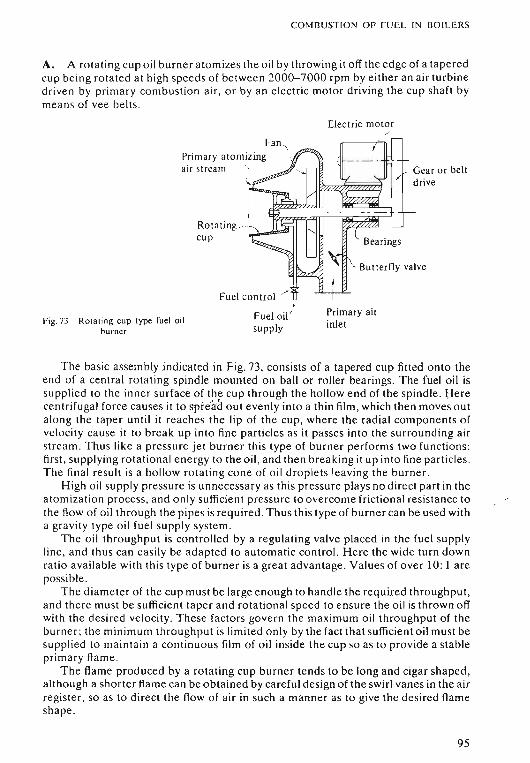
COMBUSTI ON OF FUEL IN BOILERS
A. A rot ating cup oil burner ato mizes the oil by throwing it off the edge of a taperedcup being rotated at high spe ed s of between 2000-7000 rpm by either an air turbinedr iven by primary combustion a ir, or by an electri c mot or driving the cup shaft bymean s of vee belts.
Electric motor./
. Gear or beltdrive
Prim ary airinlet
Fuel co ntrol .>
I
Fuel oil 'supply
Rot at ing ..L-:....-~
cup
fan,Prim ar y at omizing ,air stre am "\
Fig , 73 Ro ta ting cup type fuel oilburner
The basic assembly indi cated in Fig. 73, con sists of a tapered cup fitted onto theend of a cent ra l rotating spindle mounted on ball or roller bearings. The fuel oil issupplied to the inner surface of the cup through the hollow end of the spindle. Herecentrifugal force causes it to spi-e'i1aout evenly into a thin film, which then moves outalong the taper until it reaches the lip of the cup, where the radi al compo nents ofvelocity cau se it to break up into fine particl es as it passes into the surro unding airstream. Thus like a pressure jet burner this type of burner performs two functions :first, supplying rot ational energy to the o il, and then breaking it up into fine particles.The final result is a hollow rotating cone of o il droplets lea ving the burner.
High o il supply pressure is unnecessar y as this pressure plays no dir ect part in theatomization process, and only sufficient pre ssure to overcome friction al resistance tothe flow of oil through the pipes is requi red. Thus this type of burner can be used witha gra vity typ e oil fuel supply syst em.
The oil th roughput is controlled by a regulating valve placed in the fuel supplyline, and thus can easily be adapted to aut om atic control. Here the wide turn downratio available with this type of burner is a great advantage. Values of ove r 10: 1 arepossible.
The diameter of the cup must be large enough to handle the required throughput,and there mu st be sufficient taper and rotati on al spe ed to ensure the oil is thrown offwith the de sired ve loci ty. These factors govern the maximum oil throughput of theburner ; the min imum throughput is limited only by the fact that suffi cient o il must besupplied to maintain a co ntinuous film of o il inside the cup so as to provide a stableprimary flame.
The flame pr oduced by a rotating cup burner tends to be long and cigar sha ped ,although a shorter flame can be obtained by car eful design of the swirl vanes in the airregister, so as to dir ect the flow of air in such a manner as to give the de sired flam eshape.
95
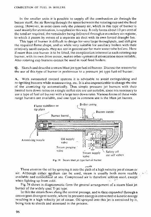
COMBUSTION OF FU E L IN BOILERS
In the sma ller units it is po ssible to supply all the combustion air through theburner itself, the air flowing through the space between the rotating cup and the fixedcasing. However, in most cases only the primary air , which in this type of burner isused mainly for atomization , is supplied in this way . It only forms about 10 per cent ofthe total a ir required , the remainder being delivered through a secondary air register,to whi ch it passes by means of a separate air duct with its own forced draught fan.
This type of burner is difficult to design for very large throughputs, and still givethe required flame shape , and so while very suitable for auxiliary boilers with theirrelatively small outputs, they are not in general use for main wat er tube boilers. Hereif more than one burner is to he fitted , the complication inherent in each rotating cupburner, with its own dri ve motor, makes other systems of atomization more suitable .Also rotating cup burners cannot be used in roof fired boilers .
Q. Sketch and describe a steam blast jet type fuel oil burner . D iscus s the reasons forthe use of this type of burner in preference to a pressure jet type fuel oil burner.
A. With automated control systems it is advisable to avoid extinguishing andre-igniting burners while manoeuvring, etc. It is also impracticable to change th e sizeof the atomizing tip automatically . Thus simple pressure jet burners with theirlimited turn down ratios on a single orifi ce size ar e not sui tab le , since it is necessary touse a typ e of fuel oil burner with a large turn down rat io. Various forms of these widerange burners are availabl e, and one type in common use is the blast jet burner.
Safet y oilcut off valves
~oile r cas ing
Burner carrier
"
Steam supplyvalve
Steam blast je t type fuel oil burner
Oil supplyvalve
Steam purging 'va lve
Fig. 74
Burner barrel ')
Flame stabilizer o rtip plate
,~
Atomizing nozzle
,.....,v.These atomize the oil by spraying it int o the path of a high velocity jet of steam or
air. Although e ither 13/,.edium can be used, steam is usually both more readily ( <.,
av ailable and ecoYloMical at sea. Compressed air is therefore seldom used, exceptwhen lighting up from cold. ' ,, '
Fig. 74 shows in diagrammatic form the general arrangement of a steam blast jetburner of the widely used Y-jet type .
In this the ste am flows along the central passage, and is then expanded through aconvergent divergent nozzle, where its pressure energy is converted to kinetic energyre sulting in a high velocity jet of steam, Oil sprayed into this jet is entrained by it ,being torn to shreds and atomized in the process,
96
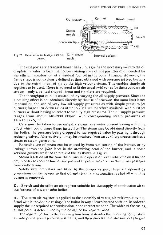
COMBUSTION OF FU EL IN BOILERS
Oil passage
Ste amnozzle
Cap nut Burner barrel
Steam
(Internal gaskets
The exit ports are arranged tangentially, thus giving the necessar y swirl to the oildroplets in order to form the hollow rotating cone of fine particles of oil needed forthe efficient combustion of a residual fuel oil in the boiler furnace . However, theflame shape is not so clearly defin ed as those obtained with pre ssure jet type burnersdu e to the entrainment of air by the high velocity steam. Thi s enables simple airregisters to be used. There is no need to fit the usual swirl vanes for the secondary airstrea m--only a venturi sha ped throat and tip plate are required .
The throughput of oil is controlled by varying the oil supply pressure. Since theatomizing effect is not obtained directly by the use of pressure, the same limit is notimpo sed on the use of very low oil supply pre ssures as with simple pressure jetburners; large turn down rat ios of up to 20 : 1 are ther efore ava ilable with blast jetburners without having to resort to unduly high pre ssures. The oil supply pressureranges from about 140-2000 kN/m', with cor respo nding ste am pre ssures of140-1500 kN/m ' .
Care must be tak en to use only dry steam, any water present having a chillingeffect which could cau se flame instability. The ste am may be obtained directly fromthe boiler, the pre ssur e being dropped to the required value by passing it throughreducing valve s. Alternatively it may be obtained from an auxiliary source such as asteam to steam gen er ator.
Exce ssive use of stea m can be caused by incorrect se tt ing of the burner, or byleakage across the joint faces in the atomizing head of the burner, and in someversions gasket s are fitted 10 prevent this as shown in Fig . 75.
Steam is left on all the time the burner is in operati on , even when the oil is turnedoff, in order to coo l the burner and prevent any remnants of oil in the burner passage sfrom carbonizing.
Safety shut off valves are fitted to the burner carrier; these are opened byprojections on the burner so that oil and steam are automatically shut off when theburner is removed .
Q. Sketch and de scribe an air register suit able for the supply of combustion air tothe furnace of a water tube boiler.
A. The term air regi ster is applied to the assembly of vanes, air swirler plates, etc.fitted within the double casing of the boiler in way of ea ch burner position, in order tosupply the air required for combustion in the correct manner. The width o f the casingat this point is determined by the de sign of the reg ister used.
The regi sterperforms the following funct ions: it d ivides the incoming combustionair into prim ary and secondary streams, and then directs these streams so as to give
97
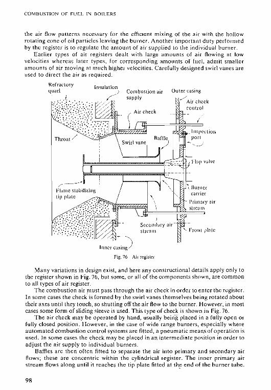
COMBUSTION OF FU EL IN BOILERS
the air flow patterns necessary for the efficient mixing of the air with the hollowrotating cone of oil particles leaving the burner. Another important duty performedby the register is to regul ate the amount of air supplied to the indi vidual burner.
Eariier types of air registers de alt with large amounts of air flowing at lowvelocities whereas later types, for corresponding amounts of fuel, admit smalleramounts of a ir mo ving at much higher velocities . Carefully designed swirl vanes areused to direct the air as required.
Refractoryquarl
Throat /
Insulation) Combustion air Outer casing
supply , /
. Inspectionpori
- •....._..J
Flap valve
l13urnercarrier
Primary airstream
j
Secondary air -stream -; Front plate
/
I.,c;::JFig.76 Air register
Many variations in design exist , and here any constructional details a pply only tothe register shown in Fig. 76, but some, or all of the components shown, a re commonto all types of air register.
The combustion air must pass through the air check in order to enter the register.In some case s the check is formed by the swirl va nes themselves being rotated abouttheir axes until they touch, so shutting off the air flow to the burner. However, in mostcases some form of sliding sleeve is used. This type of check is shown in Fig . 76.
The air check may be operated by hand, usually being placed in a fully open orfully closed position. However, in the case of wide range burners, especially whereautomated combustion control systems are fitted, a pneumatic means of operat ion isused. In so me cases the check may be placed in an intermediate position in order toadjust the air supply to indiv idual burners.
BatRes are then often fitted to separate the air into primary and secondary airflows; these are concentric within the cylindrical regi ste r. The inner primary airstream flows along until it reaches the tip plate fitted at th~ end of the burner tube .
98
COMBUSTION OF FUEL IN BOILERS
Here the air impinges on the back of the plate, and then spills over to form a se ries ofvortices which have the effect of reducing the forward velocity of the air , and so helpsto retain the primary flame within the quarl . Various de signs o f tip plates are used ,ranging from circular flat plates to more complex swirl vanes, but a ll perform thesame basic function; i.e . the formation of the vortices which is so important inmodern air registers with their high velocity air flows.
The outer, secondary air stream passes over swirl vanes which cause it to rotate asit passes through the quarl, so giving better conditions for the mixing o f fuel and air inthe secondary flame zone. Again by careful de sign the air flow pattern can be mad e tofo rm a series of vortices . In this way the forward velocity of th e burning oil particles isreduced , giving a longer period for combustion to tak e place within the furn ace . Theseconda ry air flow also has some influence on the flame shape ; this is espe cially thecase with rotating cup type burners.
A small amount of cooling air is often allowed to flow betw een th e inside edge ofthe tip plate and the atomizing tip of the burner. Thi s amo unt of air must remainsmall, otherwise it can ups et the vortex system formed by th e tip plate.
It is important that the air check forms a tight seal in order to prevent co mbustionair e nte ring the register when the burner is not in use , otherwise th ermal shoc kcau sed by the relatively cool combustion air leaking through can damage therefract ory quarles.
An insulated front plate must be fitted in some cases to prevent overheating of th ebo iler front due to radiant heat from the furnace penetrating through the gap sbetween the swirl plates, etc.
In some typ es of registers, especially those used with simple pressure jet burnerswith their small turn down ratios, very little adjustment of the relative positionsbetween the various vanes, air swirler plates, etc. can be carried out. In others awhol e range of minor adjustments may be carried out to suit different fuels,conditions of load , e tc.
It may be noted that, in the case of steam jet burners, the steam providesadd itiona l energy for the mixing of the air and fuel, and the swirl vanes for theseco nda ry air stre am may be omitted from air registers used with this type ofburner.
Q. De scribe a fuel o il system from the settling tanks to, but not including, th eburners.
A. Fig . 77 shows the diagrammatic layout of a semi-automatic fuel oil system whichmakes use of wide range burners operating on a varia ble oil supply pre ssure. Theba sic layout con sists of a ring main supplying the individiduaI burners by a series ofdead legs.
O il is pumped into the se ttling tanks, and any wat er allowed to settle out. This canthen be drained off by me an s o f spring-loaded drain cocks.
When required for usc, the high suc tion valve on the settling tank is opened andoil allowed to pass to the cold filter s fitted on the suction side side of the fuel oilservice pump.
Due to the high viscos ity of the unheated residual oil only a coarse filter, justsuffi cient to pre vent dam age to the pump, can be used at this stage. This consists of apositive displ acement pump ope rating at a constant delivery pressure. A springloaded reli ef valve fitted on the d ischarge side of the pump allows any excess oil tospill back to the suc tion side of the pump in th e eve nt of overpressure.
99
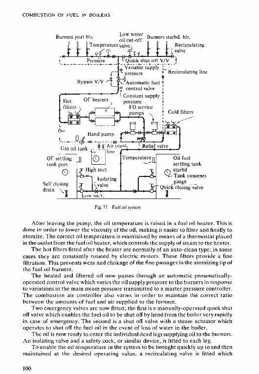
COMBUSTION OF FUEL IN BOILERS
Oil fuelsettling tank
8 starbd~ Tank contents
_.... gauge ... _Quick closing valve
I
Burners starbd. blr.
Relief valve
Isolating\ valve
Low suet.
r-Bypass V/V /!
,--
Recirculating\ valve
_L-....L.---I-~;,.-ilHo-r-l>(4-Q-Iluo-i.l.ck...L..osh-u...t-o-f.l.f-V-/V~+_____ __ _ _ ~ __ ._r_~_.J
Variable supply :pressure .- Recirculating line,
'- Automatic fuel:control valve I
.------------- tConstant supply:pressure ,
FO service :•pumps ") :,III
Low waterBurners port blr. oil cut-off
Temperature valve);'
~ Hand pump
~----_Q<Ir--~~-- -- ~w- .............~""""----G il k X i-Au prcrs_s. .....;.__- __",
as 01 tan @Iinc
OF settling 8 Temperaturetank port '--""""
8 High suet
Self closingdrain \...}
----'-"'----'-----------'----Fig.77 Fuel oil system
After leaving the pump, the oil temperature is raised in a fuel oil heater. This isdone in order to lower the viscosity of the oil, making it easier to filter and finally toatomize. The correct oil temperature is maintained by means of a thermostat placedin the outlet from the fuel oil heater, which controls the supply of steam to the heater.
The hot filters fitted after the heater are normally of an auto-clean type; in somecases they are constantly rotated by electric motors. These filters provide a finefiltration. This prevents wear and chokage of the fine passages in the atomizing tip ofthe fuel oil burners.
The heated and filtered oil now passes through an automatic pneumaticallyoperated control valve which varies the oil supply pressure to the burners in responseto variations in the main steam pressure transmitted to a master pressure controller.The combustion air controller also varies in order to maintain the correct ratiobetween the amounts of fuel and air supplied to the furnace.
Two emergency valves are now fitted; the first is a manually-operated quick shutoff valve which enables the fuel oil to be shut off by hand from the boiler very rapidlyin case of emergency. The second is a shut off valve with a steam actuator whichoperates to shut off the fuel oil in the event of loss of water in the boiler.
The oil is now ready to enter the individual dead legs supplying oil to the burners.An isolating valve and a safety cock, or similar device, is fitted to each leg.
To enable the oil temperature in the system to be brought quickly up to and thenmaintained at the desired operating value, a recirculating valve is fitted which
100
COMBUSTION OF FUEL IN BOILERS
enables oil to be circulated through the ring main back to the pump suction. Thisvalve is closed as the burners are brought into operation.
In the system shown in Fig. 77 the individual" burners are ignited by means of aparaffin torch, but in many cases automatic igniting devices are fitted . In this case it isadvisable that a flame failure alarm should also be fitted.
The system uses gas oil to flash up from cold . Air pressure supplied to the gas oilstorage tank is used to force the oil through to the burner. The use of this oilcontinues until sufficient steam has been generated to enable the fuel oil heaters to beput into operation so as to raise the temperature of the residual fuel oil to the valuerequired for its combustion.
All necessary pressure gauges, thermometers, air vents, etc. must be fitted for theproper operation of the system.
Safety fittings include quick closing valves-operated from outside the engineroom-fitted to the suction lines from the settling tanks, which enable fuel to be shutoff from the system in case of emergency. There is also an emergency stop fitted to thefuel oil service pump.
All oil lines and fittings containing heated oil should be placed above the plates, inwell-lit situations, so that any leakage can be easily detected .
The system shown can easily be changed to manual control by simply bypassingthe automatic control valve, and controlling the oil supply pressure by means of ahand jacking wheel on the spring-loaded relief valve governing the dischargepressure from the fuel oil service pump.
Q. Discuss the use of refractory materials in boilers.
A. The basic requirement of boiler refractory materials is that they should containthe heat generated in the furnace. They must therefore have good insulatingproperties and be able to withstand the high temperatures to which they will beexposed . They must also have sufficient mechanical strength to resist the forces set upby the weight of adjacent brickwork, etc.; to withstand vibration; and the cutting andabrasive action of the flame and flue dust. The materials must also be able to expandand contract uniformly without cracking.
At the present time no single refractory material can be used economicallythroughout the boiler, and the choice of suitable materials for various parts of theboiler is generally governed by the temperatures to which they will be subjected.
The material from which these refractories are manufactured can be grouped intothree main types:
Acid materials: Clay, silica, quartz, sandstone, gamister.Neutral materials: Chromite, graphite, plumbago, alumina.Alkaline or base materials: Lime, magnesia, zirconia.
it should be noted when choosing suitable materials that care must be taken toensure acid and alkaline substances are kept apart as, at high temperatures, they canreact to form salts which destroy the effectiveness of the refractory.
These refractory materials are available for installation in one of two basic forms:
FIREBRICKS
These are formed into bricks and then fired at high temperatures in special kilns .
101
COMBUSTION OF FUEL IN BOILERS
MONOLITHIC REFRACTORIES
These are supplied in an unfired state , installed in the boiler, and fired in situ whenthe boiler is put into service. This form o f refractory can be subdivided into:
Mouldable refractory This is used where direct exposure to radiant heat takesplace . It must be pounded into place during installation.
Castable refractory Placed behind wat er walls and other parts o f the boiler where itis protected from direct exposure to radi ant heat. It is installed in a sim ilar manner tobuilding concrete.
Plastic chrome ore This, bonded with clay , is used in the con struct ion of studdedwater walls. It can resist high temperatures, but has little me chanical strength, and ispounded onto steel studs welded to the tubes. These studs provide both strength andmeans of attachment for tile refractory.
All th e forms o f refractory materi als pr eviously mentioned must be securelyattached to the boil er casing and, in addition to the above-mentioned studded tubes,various types of bolts, clips, and keys are used for this purpose .
To prevent undue str esses being set up in the refractory, ample expan sion spacesmust be provided. Ca re mu st be taken to e nsure these spaces do not bec om e blockedin a ny way as thi s ca n ca use the refractory to break away from its a ttachme nts andbul ge o ut, with the danger of possible coll ap se .
Refractory materials impose limits up on the tim e required for raising steam; thegreat er the amo unt of refractory, the slowe r the ste am raising process must be inor der to prevent dam age to the refractory mat erial.
A ir checks sh ould be closed immediately the corresponding burner is shut off,o the rwise the relatively cold air impinging upon th e hot refractory ca uses a sur faceflaking, known as sp alling, to take place . This lead s to a reduction in wall th ickn ess .
Flame impingement mu st be avoided as it lead s both to a build -up o f ca rbo ndeposits, and to dam age ca use d by carbon penetrat ing into the refractory.
A no the r form of d am age is caused by im purities in the fuel: mainl y van adium andsodi um sa lts reacting with th e refractory material to form a molten slag, which thenrun s d own to th e furnace floor. This both reduces the wall thickness, and lead s to abu ild-up in the level of th e furnace floor whi ch can eventually interfere with thesha pe o f the flam e.
Q. Sketch and describe a soot blower suitable for fitt ing to a water tube boiler . Statewhy th ey are fitted.
A. In o rde r to maintain the gas side heat ing surfaces of a boiler in a cle an conditiona nd so pr event an undue build-up o f deposit s wh ich can lead to corrosion and/ o rupta ke fire s, so ot blowers are fitted .
Soot blowers con sist of two main parts, the head o r chest , and one or more nozzlesa ttache d to a tube or spindle made of heat-resistant stee l. An operating mechani smfitted in th e chest rotating and, in some cases, retracting th e nozzles as required .
The efficiency of the blower dep ends upon the conversion of pressure energy inth e blowing medium to kin eti c e ne rgy; this results in a high ve locity jet of fluidimpingin g upon the sooted surfaces .
102
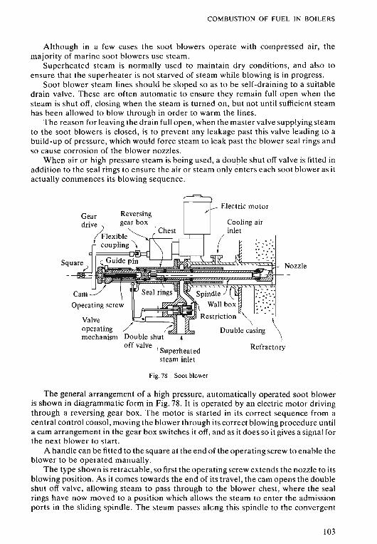
COMBUSTION OF FUEL IN BOILERS
Although in a few cases the soot blowers operate with compressed air, themajority of marine soot blowers use steam.
Superheated steam is normally used to maintain dry conditions, and also toensure that the superheater is not starved of steam while blowing is in progress.
Soot blower steam lines should be sloped so as to be self-draining to a suitabledrain valve. These are often automatic to ensure they remain full open when thesteam is shut off, closing when the steam is turned on, but not until sufficient steamhas been allowed to blow through in order to warm the lines.
The reason for leaving the drain full open, when the master valve supplying steamto the soot blowers is closed, is to prevent any leakage past this valve leading to abuild-up of pressure, which would force steam to leak past the blower seal rings andso cause corrosion of the blower nozzles.
When air or high pressure steam is being used, a double shut off valve is fitted inaddition to the seal rings to ensure the air or steam only enters each soot blower as itactually commences its blowing sequence.
Gear Reversingdrive gear box
~lexible~coupling \
Valveoperatingmechanism
Chest
tI Superheatedsteam inlet
Electric motor
Cooling airinlet
(
.... <> ..
e .. ~•• "..... " ... :,,"•• .,0
Fig. 78 Soot blower
The general arrangement of a high pressure, automatically operated soot bloweris shown in diagrammatic form in Fig. 78. It is operated by an electric motor drivingthrough a reversing gear box. The motor is started in its correct sequence from acentral control consol, moving the blower through its correct blowing procedure untila cam arrangement in the gear box switches it off, and as it does so it gives a signal forthe next blower to start.
A handle can be fitted to the square at the end of the operating screw to enable theblower to be operated manually.
The type shown is retractable, so first the operating screw extends the nozzle to itsblowing position. As it comes towards the end of its travel, the cam opens the doubleshut off valve, allowing steam to pass through to the blower chest, where the sealrings have now moved to a position which allows the steam to enter the admissionports in the sliding spindle. The steam passes alcng this spindle to the convergent
103
COMBUSTION OF FUEL IN BOILERS
divergent nozzle where the expansion process taking place results in a high velocitysteam jet.
A guide pin moving in a slot causes the nozzle to be rotated through its blowingarc while the steam is on.
To prevent high pressure steam eroding tubes in high temperature regions of theboiler, restriction or orifice plates, fitted in the steam supply passage to the individualsoot blowers, reduce the pressure as required .
Cooling air is sometimes supplied to the wall box tube. This air is normally takenfrom the forced draught fan discharge before the air heater.
104
CHAPTER 7
Boiler Operation
Q. ' Describe the process of raising steam from cold on a Scotch boiler.-"- - _.- -- - -- - _.....__.._._- _._- ..-..--_...•_'- "--_....-..._ . _ -' . ,---_.~..---- ~ ---_ ._-~,._'_.~....---.--.
A. If the boiler has been opened up for cleaning or repairs check that all work hasbeen completed, and carried out in a satisfactory manner. Ensure that all tools , etc.have been removed. Examine all internal pipes and fittings to see that they are inplace, and properly fitted. Check that the blow down valve is clear. Then carry out thefollowing procedure:
Fit lower manhole door. Check external boiler fittings to see they are in order.See that all blanks are removed from safety valves, blow down line, etc.
Fill boiler with water to about one-quarter of the water level gauge glass. Ifpossible hot water heated by means of a feed heater should be used. The initial doseof feed treatment chemicals, mixed with water, can be poured in at the top manholedoor at this stage if required . Then fit top manhole door. Make sure air vent is open.
Set one fire away at lowest possible rate. Use the smallest burner tip available .By-pass air heater if fitted. Change furnaces over every twenty minutes.
After about one hour start to circulate the boiler by means of auxiliary feed pumpand blow down valve connection, or by patent circular if fitted. If no means ofcirculation is provided, continue firing at lowest rate until the boiler is well warmedthrough especially below the furnaces . Running or blowing out a small amount ofwater at this stage will assist in promoting natural circulation if no other means isavailable . Continue circulating for about four hours, raising the temperature of theboiler at a rate of about 6°_T'C per hour. Water drawn off at the salinometer cock canbe used to check water temperature below 100°C.
At the end of this time set fires away in all furnaces, still at the lowest rate. Closethe air vent.
Nuts on manhole doors, and any new joints should be nipped up. Circulating theboiler can now be stopped, and steam pressure slowly raised during the next 7-8hours to within about 100 kN/m' of the working pressure.
Test the water gauge. The boiler is now ready to be put into service. About 12hours should be allowed for the complete operation provided some means ofcirculating the boiler is provided. If circulation cannot be carried out, the steamraising procedure must be carried out more slowly , taking about 18-24 hours forthe complete operation. This is due to the fact that water is a very poor conductor ofheat, and heat from the furnace will be carried up by convection currents leaving thewater below the furnace cold . This will lead to severe stresses being set up in thelower sections of the circumferential joints of the boiler shell if steam raising iscarried out too rapidly, and can lead to leakage and 'grooving' of the end plateflanging .
If steam is being raised simultaneously on more than one boiler, use the feedpump to circulate each boiler in turn, for about ten minutes each.
105
BOILER OPERATION
Q) Describe the procedu~~f()r_()p~!}!!.1gu_p aSco~r:.~~()iler.W!U;llinspect~be cari'ied-uurtretore-Iheboiler is again boxed up?
A. Empty the boiler, preferably by allowing the boiler to cool down , and thenrunning or pumping out. If there is not sufficient time for this, allow boiler pressure tofall to 300-400 kN/m 2 and blow down . When pressure is off the boiler, open the airvent and allow the boiler to cool down.
When the boiler is cool, make sure there is no vacuum in the boiler; this should bedone by opening the drain cock on the water level gauge glass in case the air vent ischoked.
Then commence to open up the boiler by first removing the top manhole door . Todo this, slacken back the nut s holding the dogs, but do not remove them unt il firstbreaking the joint. This precaution should be taken in the event of pressure orvacuum existing in the boiler. The nuts and dogs can then be removed, and the doorremoved . Depending upon the weight of the door, it may be necessary to rig a liftingblock to the door in order to do this.
The opening should then be roped off, and all personnel warned to keep clear.The bottom door can now be removed , again taking care when breaking the joint incase water is still above the sill of the door. If this should be the case, pump out beforeremoving door.
It is important that this sequence be followed as, when the lower door is removed,it allows a through-draught and hot vapour rising through the top door may scaldanyone standing over the hole . Hot vapour can remain in a Scotch boiler even after aconsiderable period of time allowed for cooling down .
With the doors removed, allow the boiler to ventilate before attempting to enter.Do not allow naked lights near the boiler until it has ventilated due to the danger ofexplosive gas in the boiler. If in doubt, use a safety lamp to test the atmosphere in theboiler is safe to breathe before entering.
A preliminary internal inspection should be carried out before cleaning iscommenced to check the general condition. Note scale deposits and any specialpoints.
Plug the orifice to the blow down valve to ensure it does not get choked duringcleaning operations, and place guards over the manhole landings to ensure they arenot damaged . The boiler can now be cleaned, and any internal work carried out.
When all work is completed, a full internal examination must be carried out. It isadvisable to keep a record of the boiler, consisting of a drawing on which anytroubles, rep airs , etc. can be shown, and a book in which rem arks regarding scaleformation , corrosion , deformation, etc, can be kept.
Check to see all cleaning has been carried out efficiently, especially where thetubes enter the tube plates. See that all tools and other articles have been removedfrom the boiler, paying special attention to combustion chamber top, tube nests, andbottom of boiler. Make sure all openings are clear, taking special care with the waterlevel gauge connections to ensure they are clear and free from deposits. Make sure allinternal pipes and fittings have been replaced correctly, and are secure ly attached .Th e guards can be removed, and the faces of the manhole doors and landingsinspected to see they are clean and undamaged.
Remove the plug from the blow down valve orifice . Replace the lower manholedoors, using a new joint. Operate all boiler mountings and see they work correctly.Le ave in a closed position, except for water level gauge steam and water cocks, andair vents.
106
BOILER OPERATION
The boiler can now be filled to one-quarter level in the gauge glass if steam is to beraised, or filled completely if a hydraulic test is to be carried out .
.Q.' State _th~J_~,gula,~i()nsc.;~nc.;~~l1jn,g the..~y'~.r!:,':I}.i~ t~~tiIl8. . ?f.. ~_~~?_~~E..!?~!~r.pe~_crilJ~JlQ.WY9\J WQuJd carry .out such.a.test.
~ New boilers havinga design pressure in excess of 690 kN/m 2, together with their
components, must be subjected to a hydraulic test at a pressure = (1 ,5 x des ignpressure + 350) kN/m 2 upon completion. For boilers working at pressures below thisvalue the test value is 2 x design pressure.
The test must be carried out in the presence of an authorized surveyor, who uponsatisfactory completion of the test will stamp the boiler with the official DOTstamp ifit is for a passenger vessel, or if a classification society surveyor is concerned, theirofficial stamp will be used. The surveyor's initia ls are also put on alongside the stamp,which is usually on the bottom front plate, near the furnace.
Boilers which have undergone structural repairs must be subjected to a hydr aulictest at a pressure at least equal to the design pressure .
The surveyor may call for a hydraulic test at any survey, the test pre ssure being tothe surveyor's requirements .
The procedure for such a test is carried out as follows . Close or blank off allopenings . Measuring tapes may be placed around the boiler, and deflection gauges inthe furnace . Lagging sho uld be removed as required to facilitate inspection of joints,etc.
The boiler is then completely filled with water, the air vent being left open untilwater shows to ensure no air is trapped inside. It should be noted that the use of hotwater places the boiler closer to working conditions, but may scald in the event offailure if the water is hot enough to flash off into steam with the resultant drop inpressure .
The force pump, and test gauges can now be fitted. The gauge glasses should beshut off if the test pressure is to be above the design pressure. The readings on themeasuring tapes, and deflection gauges should be noted. The boiler can now bepressurized by means of the force pump. Care should be taken to ensure that thepre ssure rises smartly in response to the pumping action; if it appears sluggish, openthe air vent to remove any air remaining in the boiler. Listen carefully duringapplica tion of pressure in case any combustion stays, etc. fracture.
Then examine all joints, especially if these are riveted. Check flanges for cracks.All flat surfaces should be checked with a straight edge for signs of bulging due to stayfailure, overheating, or thinning of the plate. Look for signs of leakage at tell-talehole s in the combustion chamber stays and welded compensating rings. Examine alltube ends for signs of leakage. Check, and note readings on measuring tapes, anddeflection gauges .
The test pressure must be maintained until the surveyor has completed hisexamin ation , and must in any case be kept on for at least ten consecutive minutes.Th e pressure can then be released . Readings on the measuring tapes and deflectiongauges should again be checked to ensure they have returned to their initial values.The boiler can then be emptied , and examined inside and out.
~~-~ie?e.scri~~. ~.proced~re for closing up', and then, raising steam on. a water tube
107
BOILER OPERATION
A. Before closing up the boiler inspect the internal surfaces to ensure they areclean, all openings to the boiler mountings clear, and tubes proved to be free ofobstruction by means of search balls, flexible wires, air or water jets.
Replace any internal fittings which have been removed, checking to ensure theyare correctly positioned and secured.
The header handhole plugs and lower manhole doors a re now replaced.Operate all boiler mountings to ensure they work freely, leaving all the valves in a
closed position.Check the gas side of the boiler is clean and in good order. Make sure the soot
blowers are correctly fitted, and operate over their correct traverse. Operate any gasor air control dampers fitted to ensure they move freely for their full travel. Leavethem closed or in mid-position as necessary . The boiler casing doors are nowreplaced.
Open the direct reading water level gauge isolating cocks, together with all boilervents, alarm and pressure gauge connections. The superheater drains are alsoopened. Check that all other drains and blow down valves are closed.
Commence to fill the boiler with hot de aerated water. At this stage the initial doseof chemical treatment can be added through the top manhole doors, which are thenreplaced.
Continue to fill until water just shows in the water level gauges. Close any headervents as water issues.
Remove the funnel cover, and ensure that all air checks operate correctly and thatthe forced draught fans are in working order. If gas air heaters are fitted they shouldbe by-passed.
Check the fuel oil system to ascertain it is in good order. Start up the fuel oilservice pumps and check for leaks. The boiler is now ready to commence raisingsteam .
Heat the fuel oil to the required temperature, using the recirculating line to getthe heated oil through the system. If no heat is available for this, use gas oil untilsufficient steam is available to heat the residual fuel oil normally used .
Start the forced draught fan , and with all the air checks full open purge the boiler,making sure any gas control dampers are in mid-position so giving a clear air passage.
Carry out a final check to make sure water level gauge cocks are open, water isshowing in the glass, and that steam drum and superheater vents are open.
Now close all the air checks except for the burner to be flashed up, this being doneby means of ignition equipment or a paraffin torch . Use the lowest possible firingrate. Adjust the air supply so as to obtain the best combustion conditions and checkthat , as the boiler heats up , the water level in the glass begins to rise.
After about one hour steam should show at the drum and superheater vents and,when issuing strongly, open the superheater circulating valve and close the air vents.
When the steam pressure has reached a value of about 300 kN/m 2 blow throughthe water level gauges to ensure they are working correctly . The isolating valves onthe remote reading water level indicator can now be opened, and the indicatorplaced in service .
With the steam pressure at about 1000 kN/m 2 follow up the nuts on all new boilerjoints.
At a pressure of about 1400 kN/m 2 open the drains on the auxiliary steam lines ,crack open the auxiliary stop valve and warm the auxiliary line through . Now closethe drains and fully open the auxiliary stop valve .
108
BOILER OPERATION
Various auxiliary equipment such as fuel oil heaters, turbo-feed pumps, etc . canbe put into service and, provided this entails a flow of steam through the superheater,the superheater circulating and drain valves are closed.
Bring the boiler up to working pressure, keeping the firing rate as steady aspossible, and avoiding intermittent flashing up.
Check the water level alarms.Open the main steam line drains, and crack open the main stop valve and warm
through the main steam line. Then close the drains and fully open the main stopvalve.
The procedure from flashing up to coupling up at full working pressure shouldtake about four to six hours. Only in emergency should it be carried out more rapidly.If new refractory material has been installed carry out the procedure more slowly.
At all times during the raising of steam the superheaters must be circulated withsteam to prevent them overheating. If the temperature of the superheaters goesabove the permitted value for the boiler reduce the rate of firing.
It must be noted that, due to the great variety of water tube boiler designs in use,the foregoing procedure is only to be taken as a guide; for example, header boilerswith their greater amount of refractory material will require about eight hours toreach full pressure. Thus the engineer should always follow the procedure laid downfor his particular boiler, which may vary in detail from the basic principles previouslystated.
Q. Describe the procedure for carrying out a hydraulic test on a water tube boiler. Towhat pressure would you subject the boiler for purpose of testing.
A. New boilers having a design pressure in excess of 690 kN /m 2 together with theircomponents must be subjected to a hydraulic test at \ ·5 times the approved designpressure, carried out to the surveyor's requirements.
Although the surveyor may call for a hydraulic test at survey, it is not normallyrequired for routine survey unless limited access prevents a practicable visual examination. After repairs to pressure parts a hydraulic test to 1·25 times working pressure isusually accepted; for minor repairs such as tube renewal, testing to just below workingpressure will suffice.
For purpose of testing the boiler is considered to extend from economiser inlet tomain steam stop valve.
Before testing, carry out a thorough inspection of the boiler to ensure that allnecessary work has been completed, all internal surfaces are clean, and all tools etc.have been removed. Remove any casing as necessary for a proper inspection of thepressure parts undergoing test. In seme instances it may be necessary to remove someof the boiler insulation.
Gag the safety valves and shut off the water level indicators, alarms etc. if goingabove the working pressure, and isolate or blank off any parts not designed to withstand the test pressure. Pay particular attention to attemperators or de-superheaters,as these are often designed to cope only with the differential pressures between thedrum and superheater; it may be necessary to equalise pressures across them during thetest , in some cases by slacking back one of the flanged connections.
Check that all valves operate freely and seat properly. Then close all valves, drainsetc . on the boiler but leave all vents open. All manhole doors can be closed, and anyheader plugs replaced.
109
BOILER OPERATION
Fit the force pump and any test gauges required, ensuring that these are properlycalibrated.
Start to fill the boiler using water as close to the metal temperature as possible, butnot less than 7'C, as any sudden change in temperature such as may be caused by fillinga warm boiler or superheater with cold water may cause leakage by way of expandedjoints. The boiler must also be protected against mechanical or thermal shock duringthe test, so never put a hydraulic test on a hot boiler or superheater. During filling,check for leaks, open drains etc . and if an y are found stop filling until they are rectified .Close vents as water issues from them, continuing to fill until the boiler is completelypressed up, and all air is released .
The force pump can now be used, building up the pressure slowly so as to avoidshock . If the pressure does not begin to rise with the first few strokes of the pump, checkall vents to ensure that all air has been released.
When fully pressurised, check all visible seams, expanded joints etc . for signs ofleakage or distortion, maintaining the test pressure for at least 30 minutes.
With inspection completed, slowly release the test pressure. If any leaks have beendetected, the water level need only be dropped sufficiently for the leak to be recified.Retest until no leakage occurs.
Before draining the boiler it is a convenient time, after the gags have been removed,to use hydraulic pressure to reset the safety valves ifrequired. They will then only needa final adjustment under steam.
Should raw water have been used for testing, completely drain and then flush outthe boiler with distilled water before returning to service.
~__~ive ~he b~sics~rvey procedure tobe carried out on a marine boiler.
A. Surveys are carried out to ensure that the boiler is in a safe working condition andlikely to remain so until the next survey. Main water tube boilers of passenger ships aresurveyed annually, while for cargo ships bi-annual survey is sufficient. The normalprocedure for auxiliary boilers is bi-annual for the first eight years, thereafter annual,although a concession may be made for auxiliary water tube to continue on a two yearcycle, provided that they are in good condition and with good records, especially thosefor water treatment.
The survey will cover the boiler from burner front, or exhaust gas inlet, to funneltop, including all pressure containment parts, valves and fittings .
During the survey the boiler , economiser and air heater are to be examined bothinternally and externally as far as access permits, and where considered necessarypressure parts subjected to a hydraulic test. Thickness of plates and tubes is to bedetermined, usually by ultrasonic test equipment.
The principal boiler mountings are to be examined externally, and opened up forinternal inspection where considered necessary. Boiler casings, supports etc. will beexamined to see they are in good order, and allow for free expansion. Automaticcontrol equipment for water level and for fuel oil is to be checked, with special regard tosafety cut-outs.
Isolate the boiler from all working systems, and open up both water and gas sides,removing any internals necessary for a proper visual examination. A visual inspectionshould be made to ascertain general boiler conditions, before it is cleaned both internally and externally.
Previous records, if any, should be examined and note taken ofany previous defectsor repairs, so these can be given special attention . A convenient survey procedure
110
BOILER OPERATION
taking into account the layout of the boiler should be decided upon. This will vary fromone boiler to another, but a typical procedure will be as follows . The steam drum isexamined internally and externally together with its mountings, then all top headersand the burner positions, including carriers and associated pipework. Economiser andsuperheater headers can be inspected before entering the water drum. Under the boiler,any mountings and supports are checked.
Do not carry out any gas side inspections until all internal examinations are complete, in order to avoid carrying grease, dirt etc. into the water spaces.
On the gas side, start with the furnace (staging may be required in large roof-firedunits). Then in turn the superheater, economiser, and air heater can be inspected.
A note pad with pencil securely attached , an unbreakable torch and a mirror on arod should be available, together with other items if desired such as a straight-edge, anintroscope to examine tube bores, and a polaroid camera to record any defects foundduring the examination. In the case of welded boilers with limited access, blanketradiography pictures using portable gamma ray equipment may be obtained, and usedto look for suspected internal foreign objects inside tubes etc.
The survey is not complete until the boiler has been examined under steam, and thepressure gauges checked against a test gauge. The water level indicators and protectivedevices must be tested, and the safety valves adjusted to their correct blow-off pressures. The fuel oil system is to be checked under pressure, and remote operated fuel oilcut-off gear tested.
In the ease of exhaust gas boilers where steam cannot be raised in port, the ship'sChief Engineer will be responsible for the correct setting of the safety valves at sea, withthe boiler survey record not being completed until he confirms that this has been donesatisfactorily.
6~1 Dis=-~~~~~me_~r. .t~.:co~~on,?r?bl~lllst~at_cal1 .arise in Jh.~.Ql?~r!!~iQ!!_oJ.JTI!l_rinel5<5{lers.----.A. Boiler damage can be considered under five main headings: corrosion, erosion,overheating, cracking and mechanical damage.
Corrosion There are two principal forms of corrosion. One is direct chemical attackand mainly occurs in superheaters due to the high metal temperatures involved. It canresult in pitting or cracking in tube bores, or in scaling or flaking on the gas side oftubes. This form of corrosion also occurs when loss of water circulation causes themetal to overheat in the presence of steam.
The more cornon form ofcorrosion found in boilers is the result ofelectro-chemicalattack usually involving acidic water conditions in the presence of dissolved oxygen.General wastage of the boiler metal due to this form of attack has been virtuallyeliminated by the use of chemical feedwater treatment, but isolated pitting can stilloccur if the treatment is not operated within the correct limits. It may be found alongthe water level in the drum, generally as the result of poor shut-down and storageprocedures where the boiler is left partly filled with cold water. Pitting along the roofofthe drum can result from condensation. In the lower parts of the boiler it can be due topoor drainage, pools of water remaining in drums and headers. However, isolatedpitting can also result from operating with the boiler water allowed to remain at tooIowa pH value, and in this case will also tend to occur in the bores of tubes subjected tothe highest rates of heat exchange, such as screen and water wall tubes.
III
BOILER OPERATION
Erosion This is a mechanical wearing away of the boiler metal due to water, steam orgas flowing over the metal surface. Thus tubes can wear thin in the region of bends, dueto water impingement, or wear externally as they stand in the flow of hot abrasive gasesleaving the furnace . Serious local ero sion can result from the direct impingement ontothe tube surface of a steam jet from a badly aligned soot blower.
Overheating In-service boiler metal subjected to the heat of combustion must becontinually cooled by water or steam . If for any reason this cooling affect is lost , orgreatly reduced, the boiler metal overheats, loses strength and distorts. This can resultin expanded tubes pulling out of tube plates, local bulging of tube surfaces with eventual rupture, the sagging of superheater tubes between their supports, etc.
Loss of water brings about the most immediate and serious damage, but loss ofcirculation through tubes will also quickly result in damage. A build-up of deposits onthe water side acts as an insulating layer, reducing the rate of heat transfer through themetal so causing it to overheat and leading to eventual distortion . Oil entering theboiler only forms a thin, but efficient, insulating layer upon heated surfaces, but alsoencourages a further build -up of scale deposits.
Superheaters at their operational metal temperatures are very vulnerable to overheating, and a circulation of steam through them must be provided at all times whenthe boiler is steaming, circulating to atmosphere if not load is available. Priming andcarry-over must be avoided, as impurities passing over with the water will result in abuild-up of deposits in the superhea ter tubes, again causing eventual overheating.
Dire ct flame impingement onto water walls will lead to overheating and distortion.Fire in uptakes or superhea ters due to a build up ofdeposits in the gas passages can alsoresult in serious overheating and damage even to pressure paris of the boiler .
Cracking Welded boilers are especially vulnerable to fatigue cracking resulting frombad design , poor workmanship or both . Cracks of this nature, even if starting in aminor weld, can continue to propagate even into the main shell plate .
Fatigue cracking is also associated with thermal cyclic stressing, which can resultfrom poor steam-raising pro cedures, lack of expansion, or even from a continualcarry-over of water droplets causing cracking inside superheater headers.
Over-expansion of tubes into tubeplates can lead to cracking of the bellmouthingand in some cases to cracks forming in the tubeplate between the holes.
Cracking due to caustic embrittlement can take place in boilers of riveted construction , due to slight leakage allowed to continue over a period of time in a riveted scam .
Mechanical Damage This can result from poor workmanship, such as damage totube plates by over-expanding during tube attachment, scoring of joint faces, distortion of doors by overtightening.
Another source of damage are explosions in the furn ace due to bad flashing-upprocedures . These can be especially serious in roof-fired rad iant heat boilers with gastight water wall panels; the force of the explosion acting directly upon these ean causethem to suffer severe distortion . It is normal practice to warm this type of furn ace withheated air etc . before attempting to flash up from cold.
Q. State the general precautions to be followed by a watchkeeper in charge ofa watertube boiler installation.
112
BOILER OPERATION
A. The watchkeeping officer must familiarise himself with the plant of which he is incharge, and,be aware of all individual equipment operating control signa ls, flow rates,temperatures and general load conditions. He must check these regularly so as tobecome aware quickly of any deviations from the norm. Rarely do emergency conditions arise without some previous indication, which an alert watchkeeper should recognise, investigate, a nd then take corrective action before the situation gets out of hand.
Ensure that all boiler and associated safety shut-down devices are maintained infull operational condition, a nd tested at regular intervals so as to be ready for instantoperation . All alarm and automatic control systems must be kept within the manufacturer's recommended operating limits. Do not allow equipment to be taken out ofoperation for reasons which could reasonably be rectified .
All control room check lists must be kept up to date, with any known deviationsfrom normal operating procedures noted, both for immediate reference and to informoncoming watchkeepers of the ongoing situ ation. Remember that any det erioration inwat ch keeping standards can give rise to circumsta nces whereby deviations remainun-noticed and may build up to potentially serious conditions.
Automatic control loops do not think for themselves, and subjected to externalirregularities will still try to perform as normal. This can result in their final controlaction being incorrect, or to some other piece of equipment being overworked in anattempt to compensate . In situa tions where the automatic control of critical parameters is not dependable, or where it becomes necessary to use manual control,reduce operating conditions so as to increase acceptable margins of error.
High performance water tube boilers demand high qu ality feed water, so do nottolerate any deterioration of feed water conditions; immediately trace the source ofanycontamination, and rectify the fault.
Do not neglect leakage of high pressure, high temperature steam, as even minorleaks will rapidly deteriorate. No attempt sho uld be made to approach the site ofleakage directly, but the defe ctive system sho uld be shut down as soon as is practicableand the leakage rectified. Do not allow steam and water leaks to go un-corrected as,apart from reduction in plant efficiency , they also lead to increased demand for extrafeed with an inevitable increase in bo iler water impurities .
Alw ays be alert fo r conditions which increase the potential fire risk within theengine room: the best method of fire fighting is not to allow one to start. Thus allspaces, tank tops etc. mu st be kept clean, dry, and well lit. This not only improves thework environment, but also makes for the early detection of any leakage and encourages early repai r.
Store an y necessary stocks of combustibles remote from sources of ignition. Maintain all oil systems tight and free from leaks and overspills.
Follow correct flashing-up procedures for the boiler at all times, especi ally in thecase of roof-fired radiant heat boilers.
Be familiar with the ship's fire fighting systems and equipment, and ensure that a llunder your direct control are kept a t a full state of readiness a t all times.
Asse ss particular risk areas, especially in engine room sp aces, and formulate yourapproach in case of emergency; decide in some detail how you would deal with fires a tva rious sites in the engine room.
Make sure that your are familiar with the quick closing fuel shut-off valves, theremotely operated steam shut-off val ves etc . to enable the boiler to be put in a safecondition if having to abandon the machinery spaces in the event of a fire.
113
BOILER OPERATION
Q. State a basic pr ocedure to be followed for the cleaning of a boiler a fter a peri od ofservice.
A. The frequency of boiler cleaning depends upon various factors such as the natureof the service in which the vessel has been engaged, the quality of feed water and fuelwith which the boiler has been supplied. In general, every reasonable opportunityshould be taken, whenever the boiler is shut down, to examine internal and externalsurfaces.
Records of uptake and superheat temperatures taken during the passage will give aguide to the condition of the boiler, as deposits forming upon any heated surfaces ofthe boiler will reduce the rate of heat transfer; thus uptake gas temperatures tend toshow an increase, while superheat temperatures decrease.
Where possible the boiler should be shut down at least 24 hours prior to cleaning,with ifpracticable the soot blowers being operated just before shut-down. When boilerpressure has fallen to about 400 kN rrn", open blow down valves on drums and headersto remove sludge deposits . Finally empty the boiler by running down through suitabledrain s etc. Do not attempt to cool the boiler forcibly as th is can lead to thermal shock .All fuel, feed and steam lines must be isolated , and the appropriate valves locked orlashed shut. Air vents must be left open to prevent a vacuum forming in the boiler as itcools down .
Internal Cleaning With boiler cooled, open the steam drum doors, followed by waterdrum doors and any bolted header plugs where fitted. Take care to avo id any remaining hot vapour or water, and allow the boiler to ventilate before making an y attempt toenter. Light covers should be fitted in place of the manhole doors to protect the bo ilerinterior when work is not in progress. With a man standing by outside the door, theboiler interior can be inspected to ascertain if cleaning is required.
Should cleaning prove to be necessary, remove any internal fittings required toprovide access to tubes etc ., keeping a record of any items removed. Also note that allattachment bolts are present, and that a\l are accounted for when refitting.
Where the boiler designpermits, cleaning can 'be carried out by mech anical brusheswith flexible drives; if these are not suita ble, chemical cleaning must be used. Aftercleaning, flush the boiler through with distilled water.
Upon completion of cleaning, tubes etc . must be proved clear. Where access isavailable, search balls or flexible search wires can be used. Where neither is practical,high pressure water or air jets can be used, the rate of disch arge from the outlet endbeing used to indicate whether any obstruction is present within the tube. Wherenecessary, welded nipples are removed to permit sighting through headers. Withwelded boilers the tubes must be carefully searched before welding takes place, andsuit able precautions then taken to avoid the entry of any foreign matter into tubes etc.Where work is to be carried out in the drum, rubber or plastic mats can be used , withflexible wires attached and secured outside the drum so that they are not left insidewhen the boiler is closed up .
Check a\l orifices to boiler mountings to prove that they are clear, and ensure thatall tools, cleaning materials etc. have been removed from the boiler. All internal fittingsremoved must be replaced . Fit new gaskets to all doors and headers, and close up theboiler.
All personnel working in the boiler must be impressed with the importance of theavoidance of any objects entering the tubes after the boiler has been searched, but thatif a mishap should occur it must be reported before the boiler is finally closed up.
114
BOILER OPERATION
External Cleaning Spaces between tubes can become choked with deposits which arenot removed by soot blowing. Where sufficiently loose they may be removed by drycleaning using brushes or compressed a ir. but in most cases water washing will benecessary.
Washing will require hot water, preferably fresh, under pressure and delivered bysuitable lances. The water serves two purposes, dissolving the soluble deposits and thenbreaking up and flushing away the loosened insoluble residue.
Once started. washing should be continuous and thorough, as any half-dissolveddeposits remaining tend to harden off, baking on hard when the boiler is again fired,then to prove extremely difficult to remove during any subsequent cleaning operations.
Prior to cleaning, a bitumastic paint should be applied around tubes where theyenter refractory material, in order to prevent water soaking in to cause external corrosion . Efficient drainage must be provided, with sometimes drains below the furnacefloor requiring the removal of some furnace refactory . Where only a particular sectionis to be washed, hoppers can be rigged beneath the work area, and the water drained offthrough a convenient access door.
For stubborn deposits a wetting agent may be sprayed on prior to washing.After washing. check that no damp deposits remain around tube ends, in crevices
etc .• removing any remaining traces found . In a similar manner remove any deposits indouble casings around economiser headers etc ., especially if they have become dampdue to water entering during the washing process.
Ensure that all cleaning materials, tools. staging etc . have been removed, and anyrefractory removed has been replaced, after whieh the access doors can be replaced.
Run the fans at full power with air registers full open for some minutes to clear anyloose deposits . Then dry the boiler out by flashing up in the normal manner. If this cannot be done immediately, then hot air from steam air heaters or from portable unitsmust be blown through to dry the external surfaces.
Q. Give a routine procedure for a soot blowing operation, suitable for use with highperformance water tube boilers.
A. Before soot blowing is commenced, ensure that sufficient reserve feed water isavailable, that the soot blowing system is in good order with correct oil levels in blowergearboxes, and that where required bearings have been lubricated with a high temperature grease. Make sure that the boiler flame failure devices and low water level alarmand cut-outs are in full working order. Note the uptake temperatures if these are notalready recorded . Then inform the bridge that soot blowing is about to start. They mayrequire time to alter course etc. and will ring back when ready.
The soot blower main steam supply valve can now be cracked open and linesallowed to warm through and drain. The drain valves, if non-automatic, are thenclosed, and the steam supply valve is fully opened. In many cases two supply valves arefitted in series, with a drain between them to ensure that no steam can leak through tothe soot blowing system when it is not in use.
Automatic combustion control can be shut off, or set to the blowing mode, whichever is applicable, and boiler operating conditions, such as superheat temperature,reduced if necessary. Shut off gas sampling lines to CO2 recorders etc . and inert gassystems if fitted . Any gas or air control dampers should be set to their optimum position for soot blowing. The combusion air fans should be speeded up unless otherwiseinstructed .
115
BOILER OPERATION
Soot blowing can nowbegin, starting with the topmost blower and then, when thishas completed blowing, proceeding to the lowest blower, operating this and the subsequent units in turn along the line of the gas flow. When the topmost blower is againreached, it is operated for a second time. Ensure that each unit performs correctly insequence and over its full traverse. Operate any faulty units manually.
Throughout the operation maintain a constant watch on boiler operating conditions, and if necessary stop blowing.
When soot blowing is finished, inform the bridge. Then restore all the boiler functions to their normal operating conditions. Close the soot blower steam supply valvesand fully open the drains. Check the reserve feed tank, and adjust the make-up feedsupply as required to restore the water level in the tank . The gas sampling lines can bereopened, together with any inert gas system fitted. Note the uptake temperatures andcompare them with previous readings; any marked variations can indicate some faultin the soot blowing system.
It is usual to operate soot blowers once every 24 hours, with rotary air heaters,where fitted, being blown every 12 hours.
116
Index
" .,. " " .Accumulat ion of pressure, 83, 87Acid attack, 63, 111Air checks, 98, 102, 108Air register, 36, 38, 92, 93, 94, 97, 99,
115Air vents, 63, 69, 105, 106, 107, ) 14Allborg boiler, 15Alloy steel, 42, 51, 55, 57Atomizat ion , 61, 91, 94Attemperators:
air cooled, 41, 58water cooled, 41,59
Automatic control, 17, 19,38,42,94,95,96,98, 103, 113, 115
Auxiliary stop valve, 67
Babcock Willcox boilers, 36, 38Baffles, 13, 15, 24, 33, 35, 40, 52, 53, 57,
98Balance connections, 60, 79, 81,82Bell mouth, 9,13,27,45,57, 112Bend test , 6Blow down effect, 83, 88, 89, 90Blow down valves, 18, 30, 68, 105, 114Blow off pressure, 21, 83, 85, 87, 89Boiler cleaning, 114, 115Boiler drum, 17,28,44Boiler feed regular, 68Boiler shell, 4Bonded deposits, 44, 45, 56, 59
Carbon deposits, 92Carryover, I) 2Castable refractory, 102Chemical cleaning, 114Chemical dosing valve, 69
117
Chrome, 57Chrome ore, 102Circumferential joint, 8Circumferential stress, I, 2Clarkson boiler, 12Cochran boiler, 10Collision chock, 7Combustion:
air , 91, 96, 98chamber, 4,7, II , 12, 18,24,73process, 91
Compensation , 3, 4, 107Composite boiler, 22, 23Condensat ion , 50, 74, IIIConduction formula , 27Consolidated safety valve, 89Control dampers, 19,38,41,53,56,60,
115Controlled superheat boiler, 51Corrosion, 9, 10, 28, 31, 44, 62, 63, 103,
IIICorten steel, 66Cracking, 12,107,111,112Cyclone steam separators, 38
Dampers, 19,38,39,41,51,53,56,57,115
Density, 30, 33, 35De-superheater, 53, 55, 60Dew point temperature, 24, 25, 63, 64Diaphragm water wall, 44, 46Double casing , 33, 34, 36, 41, 59Down comers, 15, 28, 30, 32, 34, 36, 37,
39,41 ,42,44Drain valve, 63, 69, 99, 103, 115D-t ype boiler , 35, 37, 54
INDEX
Dual pressure boiler, 20
Easing gear, 73, 85, 86, 89Economiser, 40, 52, 64Enamel coating, 66Erosion, 104, 112ESD. I typeboiler, 39ESD. II typeboiler, 41ESD. III typeboiler, 42Excess air, 42, 44, 47, 93Exhaust gas boiler, II, 15, 16,21 ,22,25,
III
Fatigue cracking, 12Feathering, 85, 87, 89Feed water check valve, 67Flame failure device, 12, 19, 101, 115Flash off, 69Forced circulation boiler, 16, 17, 18,24,
25Force draught fan, 18Foster wheeler boiler, 35, 39,40Fuel oil system, 100Full bore safety valve, 85Full lift safety valve, 86Furnace, 7, 10, II, 12, 13, 14,35,43
Gamma ray equipment, 'IIIGas/air heater, 8, 43, 64, 65, 108Generating tube, 15, 24, 31, 33, 34, 35,
37,38,43,44Girder stay, 7, 8Gusset stay, II
Handhole door, IIHeader, 15,27,30,33,36,39,56
. Header boiler, 33, 64, 109Hemispherical furnace, II, 18Hollow column, 72Hopkinson safety valve, 87Hydraulic test, 30, 107, 109, 110
Igerna gauge, 78Ignition temperature, 92
Improved high lift, 83Internal cleaning, 106, 114Integral furnace boiler, 36, 84Internal inspection, 106, 108, 110
Joint efficiency , 2
Kaldo steel , 5Kinetic energy 96, 102
Latent heat, 19,49,50LD steel, 5Longitudinal joint, 1,2,8,29Louvre plate, 77Low water level alarm, 19, 68, 80, 81, 83,
115
Main stop valve, 67Manhole door, 2, 4, 8, II, 13, 15, 18,20,
29, 30, 38,40, 105, 106, 108, 109Manoeuvring, 51, 55Membrane water wall, 46Mica, 76, 77Multi-loop economiser, 62Multi-loop superheater, 39,41,45,57Multi-tubular boiler, 7Molybdenum, 32, 57Monolithic refractory, 102Mono water wall, 41, 43, 46
Natural circulation,Nozzle reaction, 86
Ogee ring , 10, II , 12, 13Oil contamination, 19,20, J 12Orifice plate, 61, 94, 104Overheating, 10, II , 12, 31, 53, 54, 55,
58, 73, III, 112
Package boiler, 18Parallel flow, 17,42, 52, 64pH value, IIIPlate glass gauge, 75, 76Pop action, 89
118
Pressure jet burner, 93Primary combustion air, 92, 97Primary flame, 92Primary superheater, 40, 41, 44, 59Priming , 112
Quarl , II, 92, 99Quick-closing valve, 100, 113
Radiant heat, II, 15, 31Radiant heat boiler, 31, 32, 44, 65Raising steam, 105, 107Recirculating valve, 100Reflex water gauge, 75Refraction, 71, 73, 75Refractory, II, 12, 15,36,38,40,41 ,46,
48,99,101 ,102Relief valve, 63Remote reading gauge, 78, 108Riser, 32, 36,44Riveted joint, 3, 5, 6, 8, II , 14,28, 107,
112Roof firing, 42, 112, 113Rotary air heater, 44, 65Rotary cup burner, 95
Safety valve, 19,21,55,67,73,83,85,86,109, III
Salinometer valve, 69, 105Scale, 8, 14,20,28,106, 112Scotch boiler, 7, 8, 18,27,64, 70, 105,
106107Screen tube, 31, 33, 35, 37, 38,41,52,
57, IIIScum valve, 69Seal welding, 10Secondary combustion air, 93, 97Secondary flame, 92Secondary superheater, 40, 41, 42, 44,59Selectable superheat boiler, 38, 55Settling tank, 99Single boiler casing, 41,44,47Smoke box, 8, II, 14, 18Smoke tube , 8, 9, 14
INDEX
Sodium, 52, 63, 64Soot blower, 41, 43, 63, 64, 65, 66,102,
108,115Soot blower master valve, 70, 103, J 15Spanner boiler, 14Spheroid boiler, IISpheroidal furnace , 11Spray type attemperator, 45Spray type de-superheater, 51,61Steam/air heater, 66Steam blast jet burner, 96, 99Steam drum, 15, 16,22,28,30,33,35,
38,39,41,43,59,60,67,68,78,81,108, III
Steam/steam generator, 19Steaming economiser, 45, 64Stay, 5,7, II, 13, 15, 18Stay tube , 8, 9, II, 12, 15, 18Stub tube , 29Studded tube, 36, 38, 46Sulphur, 63, 93Superheater circulation, 52, 53, 55, 58,
60,67,69Superheater circulating valve, 69Superheater support tube, 32, 45, 51, 52,
54, 56, 57, IIISuperheater temperature control, 33, 34,
36 38, 40, 41, 42, 44, 45, 51, 53, 55, 58Superheater tube , 32, 39, 52, 55, 56, 58Survey procedure, 110Suspended flame, 91Swirl plate, 94Swirlyflo tube, 15
Tangential firing, 43Tangential water wall, 44, 46Tank boiler, 7, 10, 14,23,25Tensile test, 6Test piece, 6, 29Testing of safety valve, 110, IIITesting of WL gauges, 71, 74, 79, 105,
108,110, IIIThermal efficiency, 22, 49Thermodisc valve seat, 89
119
Ultra-sonic test, I 10Uptake, 8, 13, 15, 18, 23, 35, 44, 57, 62,
63,64, 116Uptake fire, 63, 64, 65Uptake fouling, 63, 64, 65, 66, 99Uptake heat exchanger, 63, 64, 65Underfloortube, 35,36,37,39,41
Valve lift, 83, 85, 87Vanadium, 52, 102
120
Venturi,97Vertical boiler, 10, 12, 13, 14, 16, 23Viscosity, 91, 99,100Vortices, 91, 92, 99
Waste heat boiler, 17,22, 23Waste steam pipe, 83, 85Water circulation, 8, 13, 15, 16, 18, 20,
24, 25Water drum 30, 35, 37, 38, 39,41 ,43Water level gauge, 68, 70, 71, 73, 75, 76,
78Water wall, 15,31 ,34,35,37,38,39,41 ,
44,46Water washing, 115Welded joints, 8, 10, II , 13, 14, 15, 19,
28,38,45,46Wrapper plate, 28, 29
X-ray examination, 29
Y-jet burner, 96


![CON EXAMINATION BOARD OF BOILERS - Maharashtra · (Under The Boiler Operation . Enginee~'s. Rule, 2011) Boiler Technology - I. 5th July 2014 [TIME: 10-00 A.M. to 1-00 P.M.] (MAx](https://img.pdfslide.us/doc/110x75/5afa7da67f8b9ae92b8dd81f/con-examination-board-of-boilers-maharashtra-under-the-boiler-operation-enginees.jpg)


![[Institute for Career Research] Careers in Enginee(BookZZ.org)](https://img.pdfslide.us/doc/110x75/56d6c04b1a28ab301699c89e/institute-for-career-research-careers-in-engineebookzzorg.jpg)
![ENGINEER - Vol. XLVII, No. 03, pp. [13-25], 2014 ENGINEE](https://img.pdfslide.us/doc/110x75/616a0cb511a7b741a34e4109/engineer-vol-xlvii-no-03-pp-13-25-2014-enginee-.jpg)

![ENGINEE ENGINEER - Vol. XXXXVI, No. 03, pp. [43-54], 2013](https://img.pdfslide.us/doc/110x75/61f964f531858a47ee2a5cc0/enginee-engineer-vol-xxxxvi-no-03-pp-43-54-2013-.jpg)