Embed Size (px)
Citation preview

SATURN V9104S2U V9104SKEWS2UMARS V9804S2U V9804SKEWS2U
RHINE R9804S2U R9804SERS2U
MARINE AND FLUVIAL SATELLITE TV ANTENNAS WITH USB CONTROL UNIT
SERIES MK3
USER AND INSTALLATION MANUAL
SATURN MARS RHINE
42www.glomex.it
EN
GL
ISH
SATURN MARS RHINE
43www.glomex.it
EN
GL
ISH
INDEX
1. FOREWORD . . . . . . . . . . . . . . . . . . . . . . . . . . . . . . . . . . . . . . . . . . . . . . . . . . . . . . . . . . . 441.1 DELIVERY LETTER. . . . . . . . . . . . . . . . . . . . . . . . . . . . . . . . . . . . . . . . . . . . . . . . . . . . 441.2 ANTENNA IDENTIFICATION. . . . . . . . . . . . . . . . . . . . . . . . . . . . . . . . . . . . . . . . . . . . . 441.3 WARRANTY. . . . . . . . . . . . . . . . . . . . . . . . . . . . . . . . . . . . . . . . . . . . . . . . . . . . . . . . . . 441.4 GENERAL SAFETY RULES . . . . . . . . . . . . . . . . . . . . . . . . . . . . . . . . . . . . . . . . . . . . . 451.5 ENVIRONMENT. . . . . . . . . . . . . . . . . . . . . . . . . . . . . . . . . . . . . . . . . . . . . . . . . . . . . . . 45
2. PRODUCT DESCRIPTION . . . . . . . . . . . . . . . . . . . . . . . . . . . . . . . . . . . . . . . . . . . . . . . . 462.1 SATURN V9104S2U - V9104SKEWS2U - MARS V9804S2U - V9804SKEWS2U . . . . 462.2 RHINE R9804S2U - R9804SERS2U . . . . . . . . . . . . . . . . . . . . . . . . . . . . . . . . . . . . . . . 46
3. CONTENTS . . . . . . . . . . . . . . . . . . . . . . . . . . . . . . . . . . . . . . . . . . . . . . . . . . . . . . . . . . . . 473.1 OPTIONAL ACCESSORIES (NOT INCLUDED) TO USE GLOMEX ANTENNAS. . . . . 50
4. NECESSARY TOOLS FOR ASSEMBLY (NOT PROVIDED) . . . . . . . . . . . . . . . . . . . . . . 50
5. INSTALLATION . . . . . . . . . . . . . . . . . . . . . . . . . . . . . . . . . . . . . . . . . . . . . . . . . . . . . . . . . 51
6. ASSEMBLY . . . . . . . . . . . . . . . . . . . . . . . . . . . . . . . . . . . . . . . . . . . . . . . . . . . . . . . . . . . . 536.1 LOWER RADOME CUTTING TEMPLATE. . . . . . . . . . . . . . . . . . . . . . . . . . . . . . . . . . . 616.2 CONTROL UNIT CUTTING TEMPLATE FOR INSTALLATION
ON A VERTICAL WALL . . . . . . . . . . . . . . . . . . . . . . . . . . . . . . . . . . . . . . . . . . . . . . . . . 626.3 SKEW CALIBRATION (MANUAL) . . . . . . . . . . . . . . . . . . . . . . . . . . . . . . . . . . . . . . . . . 636.4 SKEW ADJUSTMENT GRID FOR EUROPE. . . . . . . . . . . . . . . . . . . . . . . . . . . . . . . . . 64
7. USE . . . . . . . . . . . . . . . . . . . . . . . . . . . . . . . . . . . . . . . . . . . . . . . . . . . . . . . . . . . . . . . . . . 66
8. TIPS FOR CORRECT USAGE . . . . . . . . . . . . . . . . . . . . . . . . . . . . . . . . . . . . . . . . . . . . . 698.1 FOOTPRINTS: SATELLITE TRANSMISSION AREAS . . . . . . . . . . . . . . . . . . . . . . . . . 70
9. MAINTENANCE. . . . . . . . . . . . . . . . . . . . . . . . . . . . . . . . . . . . . . . . . . . . . . . . . . . . . . . . . 729.1 PREVENTIVE MAINTENANCE . . . . . . . . . . . . . . . . . . . . . . . . . . . . . . . . . . . . . . . . . . . 729.2 SPARE PARTS . . . . . . . . . . . . . . . . . . . . . . . . . . . . . . . . . . . . . . . . . . . . . . . . . . . . . . . 729.3 SOFTWARE UPDATE BY FLASH USB. . . . . . . . . . . . . . . . . . . . . . . . . . . . . . . . . . . . . 73
10. TROUBLESHOOTING. . . . . . . . . . . . . . . . . . . . . . . . . . . . . . . . . . . . . . . . . . . . . . . . . . . . 75
11. RESHIPPING. . . . . . . . . . . . . . . . . . . . . . . . . . . . . . . . . . . . . . . . . . . . . . . . . . . . . . . . . . . 77
12. TECHNICAL SPECIFICATIONS . . . . . . . . . . . . . . . . . . . . . . . . . . . . . . . . . . . . . . . . . . . . 78
13. TECHNICAL SUPPORT . . . . . . . . . . . . . . . . . . . . . . . . . . . . . . . . . . . . . . . . . . . . . . . . . . 80
SATURN MARS RHINE
44www.glomex.it
EN
GL
ISH
1. FOREWORD
1.1 DELIVERY LETTER
Welcome: with the installation of this antenna, theworld of satellite television comes on board yourboat.This manual has been drafted in order to help youwith the correct installation and operation of theantenna.
1.2 ANTENNA IDENTIFICATION
When calling GLOMEX or an authorized ServiceCentre, always provide the serial number and themodel of the antenna, shown on the second pageof the manual, on the packaging, on the backsideof the dish, under the control unit and under thepower supply.
1.3 WARRANTY
GLOMEX guarantees the satellite antennas seriesSATURN4 V9104S2U and V9104SKEWS2U,MARS4 V9804S2U, V9804SKEWS2U andRHINE R9804S2U, R9804SERS2U against con-formity defects for a period of 24 (twenty-four)months from the date of sales.Warranty is intended as the repair or replacementof the equipment showing conformity defects whenentering the sales contract, with no charge for thematerials.In case of conformity defects, the customer is enti-tled to the replacement of the goods with nocharge.The warranty is only valid if the product comes witha valid proof of purchase (receipt or invoice).The non-conforming product must be sent back toa Service Centre or authorized retailer, who will for-ward it to:
GLOMEX S.r.l.Via Faentina 165/G
48124, Ravenna (Italy)
along with all the accessories supplied at pur-chase.
The serial number must neither be erased normade illegible, otherwise the warranty will bevoided.
S WARNINGConserve the installation and user manual withcare! Losing the serial number makes the warrantynull and void!
The warranty does not apply in case of damagedue to carelessness, use or installation not compli-ant with the instructions given, tampering, productor serial number modification, damage due to acci-dental causes or to the buyer’s negligence.Moreover, warranty does not apply in case of dam-age consequent to connections of the equipment todifferent voltages than those indicated or to suddenvoltage variations of the network the equipment isconnected to, as well as in case of damage causedby leakage, fire, inductive/electrostatic dischargesor discharges due to lightning, use of cables differ-ent to those provided, overvoltages or other phe-nomena not related to the equipment.The parts subject to wear consequent to use suchas connection cables, driving belts, connectors,external parts and plastic supports are covered bya one-year period warranty.The following are not covered by warranty: periodicmonitoring, software updates, settings of the prod-uct, maintenance.After the expiration of the warranty period, the tech-nical support activities will be carried out chargingthe customer for the replaced parts, the labourcosts and freight charges, according to currentrates.The equipment will be replaced or repairedunder warranty only and exclusively on Glomexquality department’s approval.Should any dispute rise, the place of jurisdiction willexclusively be Ravenna (Italy).
The warranty is provided by:GLOMEX S.r.l.
Via Faentina 165/G
48124 Ravenna (Italy)
SATURN MARS RHINE
45www.glomex.it
EN
GL
ISH
1.4 GENERAL SAFETY RULES
Carefully read the instructions given and follow theprecautions indicated to prevent potential hazardsand to safeguard your health and safety, beforecarrying out any installation and maintenance oper-ation.This manual contains the following indications:
S WARNINGThis symbol warns against potential damage to theequipment which could involve the operator’ssafety.
S DANGERWith specific warnings against potential dangersfor the safety of the operator or other directlyinvolved persons.
Failure to comply with the instructions preceded bythe above-mentioned keywords (WARNING andDANGER) can cause serious accidents or eventhe death of the persons involved.Moreover, in this Manual, some instructions aregiven with text in italics, preceded by the wordNOTE.The information and specifications given in thismanual are based upon the information available atthe moment it is written.In case of doubts, do not hesitate to contactGLOMEX S.r.l.
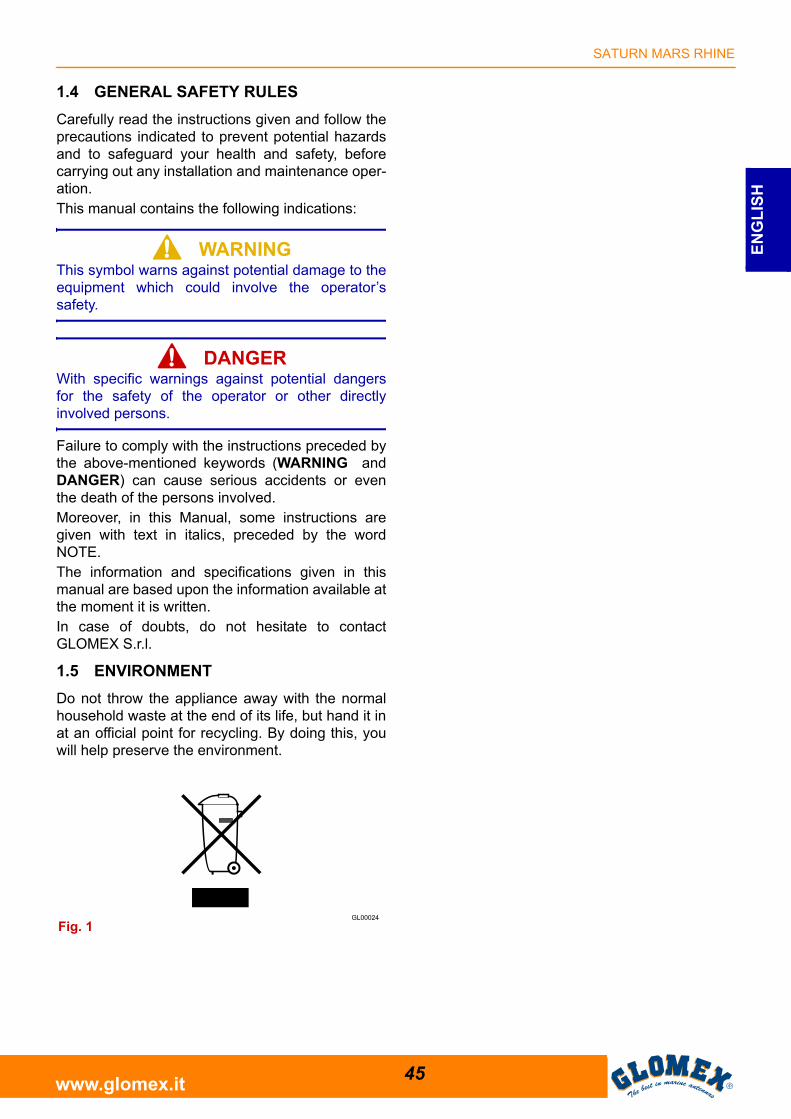
1.5 ENVIRONMENT
Do not throw the appliance away with the normalhousehold waste at the end of its life, but hand it inat an official point for recycling. By doing this, youwill help preserve the environment.
Fig. 1
SATURN MARS RHINE
46www.glomex.it
EN
GL
ISH
2. PRODUCT DESCRIPTION
2.1 SATURN V9104S2U - V9104SKEWS2U - MARS V9804S2U - V9804SKEWS2U
They are satellite antennas equipped with theDVB-S2 technology in order to be able to receivechannels in FULL HD and 4K andensure highstandards in the acquisition and maintenance ofthe satellite signal both when cruising and whenriding the anchor or at the dock. They enable con-nection of up to 16 independent decoders on thesame boat. These satellite TV antenna models areequipped with the new control unit with USB inputfor faster and easier software update. The newcontrol unit also has a built-in power supply tosimplify installation and reduce wiring.They are provided with the HPD (High-Perfor-mance Dish) parabolic dish, combined with theinnovative STO (Silent Tracking Operation) noisereduction system. They are equipped with an effi-cient compensation system of the boat’s rolling andpitching movements consisting of electronic gyro-stabilizers (EGS), a multiple coaxial rotating joint(MCRJ) and a multiswitch box for the connection ofmore independent decoders (4 outputs for multi-switch, up to a maximum quantity of 16 perantenna).The antenna can turn infinitely around its axis,since no coaxial cable winding and no interruptionof TV reception are needed. They are equippedwith a control unit which can be embedded into theon-board electric panel.In the SKEW version, they are provided with theinnovative compensation system which, accordingto the geographic position, directly operates on theLNB, automatically changing its inclination andoptimizing polarization to obtain the best possiblesignal quality. 8 satellites are already available on the control unitand are recognized through the NIT (Network Iden-tification Table) system. They are prearranged forfuture updating.
2.2 RHINE R9804S2U - R9804SERS2U
Rhine R9804S2U/R9804SERS2U is the best satel-lite TV antenna for river boats designed by Glomexand is equipped with the DVB-S2 technology inorder to be able to receive channels in FULL HDand 4K and ensure high standards in the acquisi-tion and maintenance of the satellite signal. Identi-cal in dimensions to Mars V9804S2U (dishdiameter 600 mm), it allows the connection of up to16 independent decoders on the same boat. Thisantenna is equipped with a multiple coaxial rotatingjoint (MCRJ) and with a multiswitch box for the con-nection of more independent decoders (4 outputsfor multiswitch, up to a maximum quantity of 16 perantenna). Rhine R9804S2U is equipped with the new controlunit with USB input for faster and easier softwareupdate. The new control unit also has a built-inpower supply to simplify installation and reducewiring. Rhine has been designed to obtain an out-standing performance in fluvial navigation thanks tothe new hardware and software of mobile inspira-tion, which prevent losing the satellite TV signaleven in the presence of bridges and obstaclesalong the banks. These characteristics make Rhinethe ideal choice to watch TV in river boats and incase of bad weather conditions.It is prearranged for future updating.
SATURN MARS RHINE
47www.glomex.it
EN
GL
ISH
3. CONTENTS
The satellite antenna is sent packed in a cardboardbox and sealed with the GLOMEX “SAFETY SEAL”hoop, which has the function of CONTENT WAR-RANTY seal.Upon receipt, check that:- the packaging is whole and the warranty hoop is
present;- the supply matches the order specifications;- the antenna and its accessories are not dam-
aged.In case of damage or missing parts, immediatelyinform the Retailer, if possible with appropriatephotos.
The following tables list the components containedin the package, indicating the quantities and theGLOMEX code (if provided).
SATURN MARS RHINE
48www.glomex.it
EN
GL
ISH
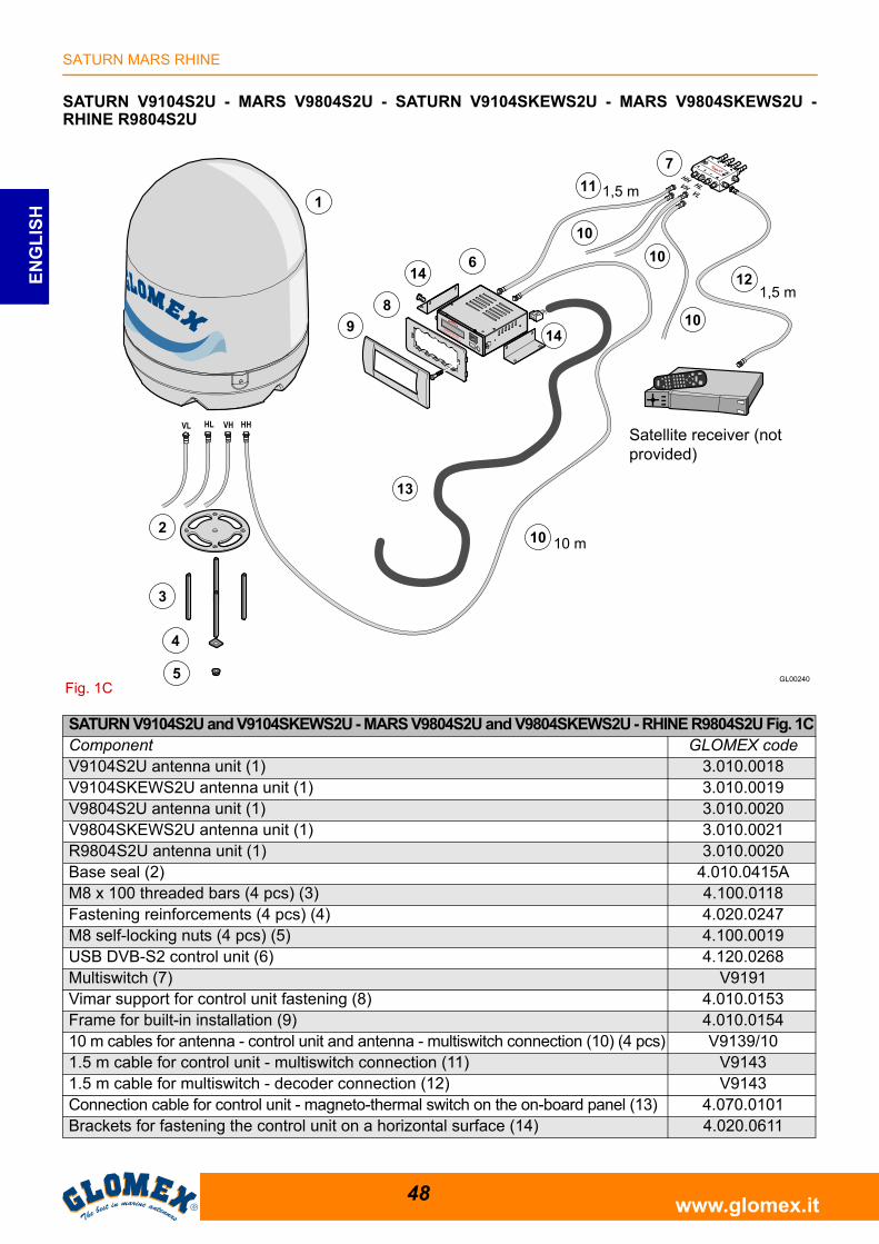
SATURN V9104S2U - MARS V9804S2U - SATURN V9104SKEWS2U - MARS V9804SKEWS2U -RHINE R9804S2U
Fig. 1C
Satellite receiver (not provided)
SATURN V9104S2U and V9104SKEWS2U - MARS V9804S2U and V9804SKEWS2U - RHINE R9804S2U Fig. 1CComponent GLOMEX codeV9104S2U antenna unit (1) 3.010.0018V9104SKEWS2U antenna unit (1) 3.010.0019V9804S2U antenna unit (1) 3.010.0020V9804SKEWS2U antenna unit (1) 3.010.0021R9804S2U antenna unit (1) 3.010.0020Base seal (2) 4.010.0415AM8 x 100 threaded bars (4 pcs) (3) 4.100.0118Fastening reinforcements (4 pcs) (4) 4.020.0247M8 self-locking nuts (4 pcs) (5) 4.100.0019USB DVB-S2 control unit (6) 4.120.0268Multiswitch (7) V9191Vimar support for control unit fastening (8) 4.010.0153Frame for built-in installation (9) 4.010.015410 m cables for antenna - control unit and antenna - multiswitch connection (10) (4 pcs) V9139/101.5 m cable for control unit - multiswitch connection (11) V91431.5 m cable for multiswitch - decoder connection (12) V9143Connection cable for control unit - magneto-thermal switch on the on-board panel (13) 4.070.0101Brackets for fastening the control unit on a horizontal surface (14) 4.020.0611
SATURN MARS RHINE
49www.glomex.it
EN
GL
ISH
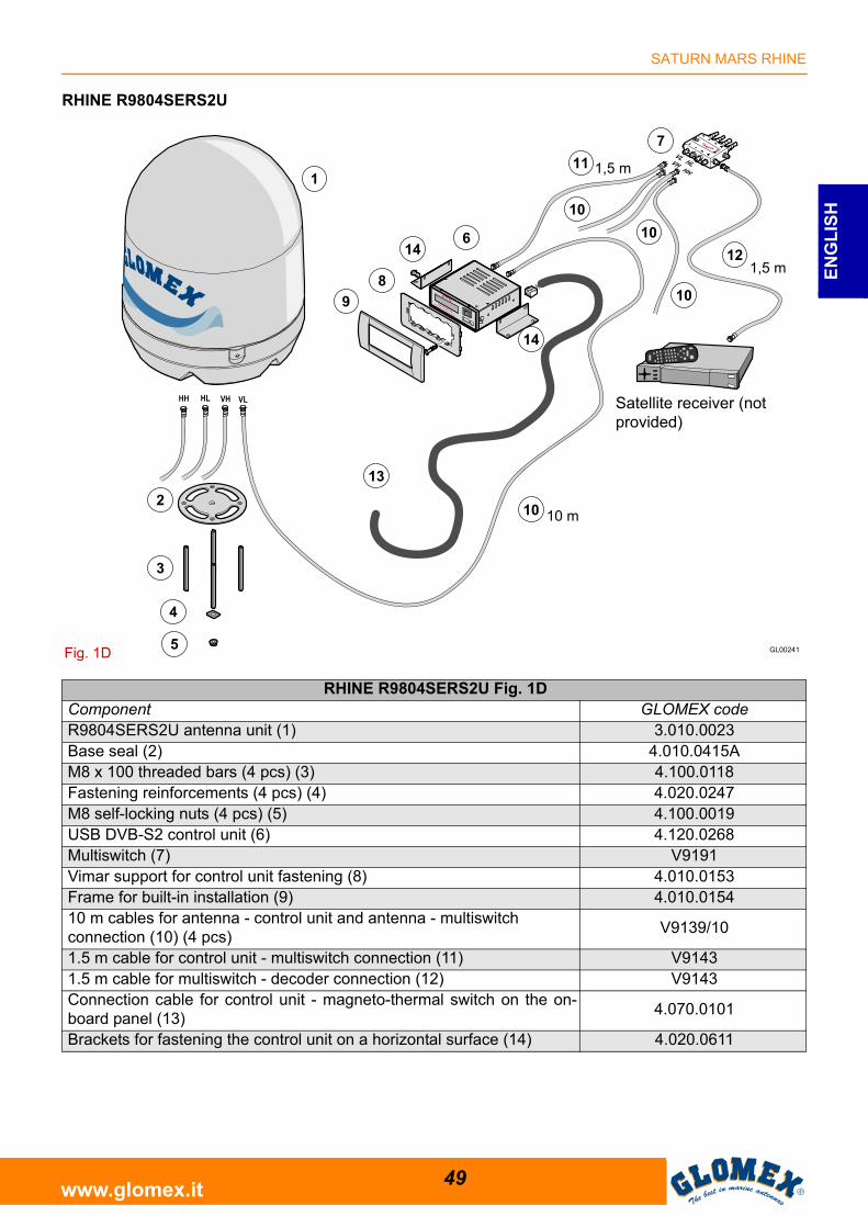
RHINE R9804SERS2U
Fig. 1D
Satellite receiver (not provided)
RHINE R9804SERS2U Fig. 1DComponent GLOMEX codeR9804SERS2U antenna unit (1) 3.010.0023Base seal (2) 4.010.0415AM8 x 100 threaded bars (4 pcs) (3) 4.100.0118Fastening reinforcements (4 pcs) (4) 4.020.0247M8 self-locking nuts (4 pcs) (5) 4.100.0019USB DVB-S2 control unit (6) 4.120.0268Multiswitch (7) V9191Vimar support for control unit fastening (8) 4.010.0153Frame for built-in installation (9) 4.010.015410 m cables for antenna - control unit and antenna - multiswitch connection (10) (4 pcs)
V9139/10
1.5 m cable for control unit - multiswitch connection (11) V91431.5 m cable for multiswitch - decoder connection (12) V9143Connection cable for control unit - magneto-thermal switch on the on-board panel (13)
4.070.0101
Brackets for fastening the control unit on a horizontal surface (14) 4.020.0611
SATURN MARS RHINE
50www.glomex.it
EN
GL
ISH
3.1 OPTIONAL ACCESSORIES (NOT INCLUDED) TO USE GLOMEX ANTENNAS
To be able to use your new GLOMEX satelliteantenna for boats, you will have to procure or buyalso:- a TV set;- a satellite receiver for channel selection.The table below lists all the GLOMEX optionalcomponents, with relevant code.
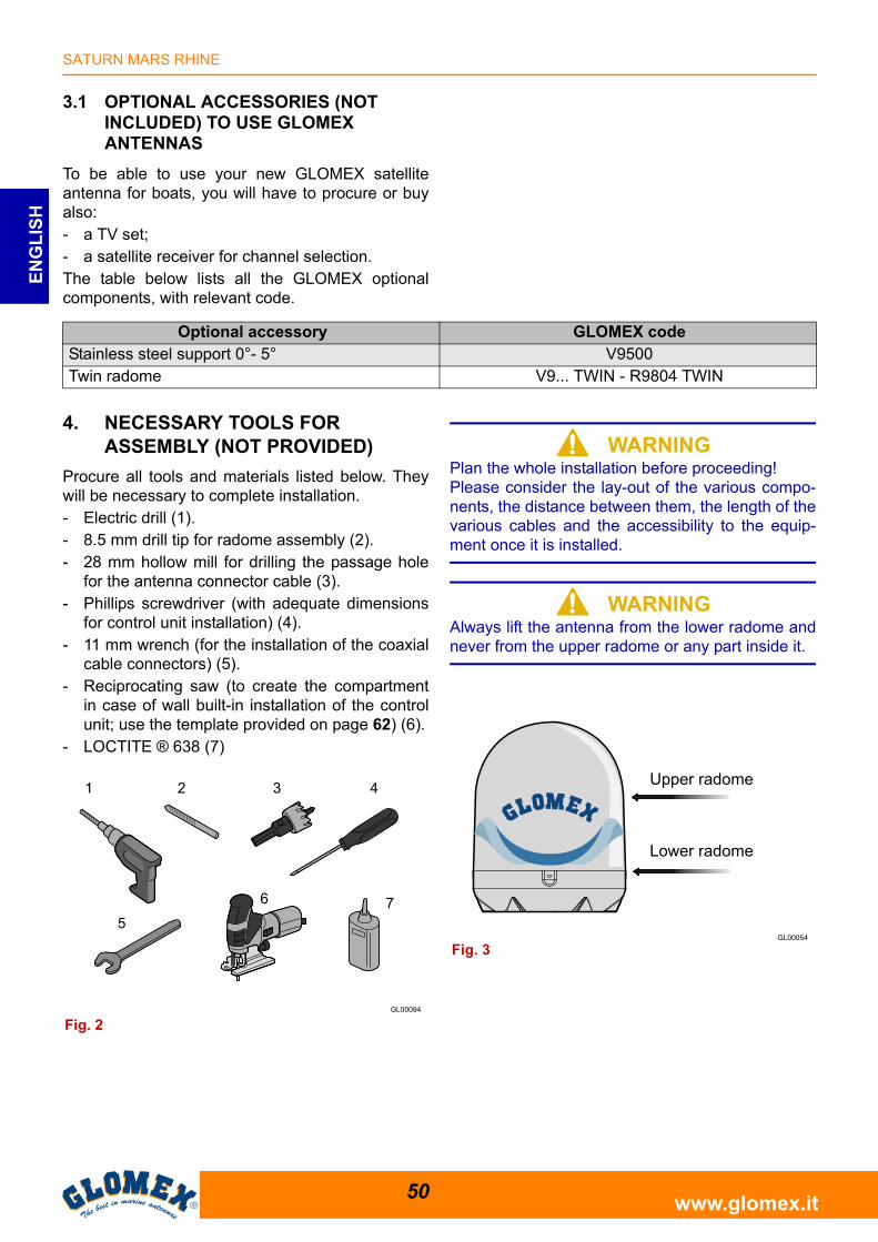
4. NECESSARY TOOLS FOR ASSEMBLY (NOT PROVIDED)
Procure all tools and materials listed below. Theywill be necessary to complete installation.- Electric drill (1).- 8.5 mm drill tip for radome assembly (2).- 28 mm hollow mill for drilling the passage hole
for the antenna connector cable (3).- Phillips screwdriver (with adequate dimensions
for control unit installation) (4).- 11 mm wrench (for the installation of the coaxial
cable connectors) (5).- Reciprocating saw (to create the compartment
in case of wall built-in installation of the controlunit; use the template provided on page 62) (6).
- LOCTITE ® 638 (7)
S WARNINGPlan the whole installation before proceeding!Please consider the lay-out of the various compo-nents, the distance between them, the length of thevarious cables and the accessibility to the equip-ment once it is installed.
S WARNINGAlways lift the antenna from the lower radome andnever from the upper radome or any part inside it.
Optional accessory GLOMEX codeStainless steel support 0°- 5° V9500Twin radome V9... TWIN - R9804 TWIN
Fig. 2
Fig. 3
Upper radome
Lower radome
SATURN MARS RHINE
51www.glomex.it
EN
GL
ISH
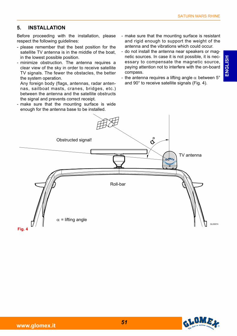
5. INSTALLATION
Before proceeding with the installation, pleaserespect the following guidelines:- please remember that the best position for the
satellite TV antenna is in the middle of the boat,in the lowest possible position.
- minimize obstruction. The antenna requires aclear view of the sky in order to receive satelliteTV signals. The fewer the obstacles, the betterthe system operation.Any foreign body (flags, antennas, radar anten-nas, sailboat masts, cranes, bridges, etc.)between the antenna and the satellite obstructsthe signal and prevents correct receipt.
- make sure that the mounting surface is wideenough for the antenna base to be installed.
- make sure that the mounting surface is resistantand rigid enough to support the weight of theantenna and the vibrations which could occur.
- do not install the antenna near speakers or mag-netic sources. In case it is not possible, it is nec-essary to compensate the magnetic source,paying attention not to interfere with the on-boardcompass.
- the antenna requires a lifting angle between 5°and 90° to receive satellite signals (Fig. 4).
Roll-bar
Fig. 4
TV antenna
Obstructed signal!
= lifting angle
SATURN MARS RHINE
52www.glomex.it
EN
GL
ISH
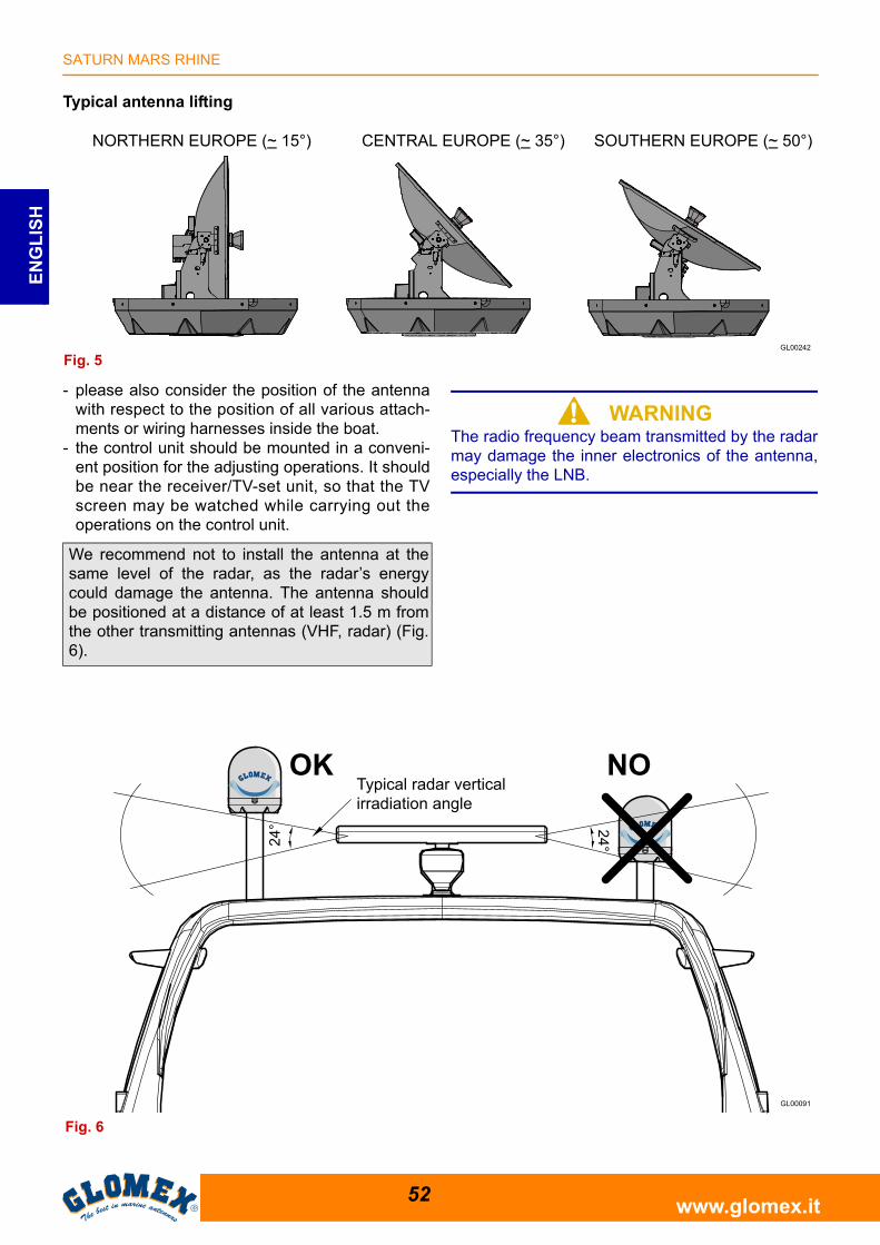
Typical antenna lifting
- please also consider the position of the antennawith respect to the position of all various attach-ments or wiring harnesses inside the boat.
- the control unit should be mounted in a conveni-ent position for the adjusting operations. It shouldbe near the receiver/TV-set unit, so that the TVscreen may be watched while carrying out theoperations on the control unit.
S WARNINGThe radio frequency beam transmitted by the radarmay damage the inner electronics of the antenna,especially the LNB.
Fig. 5
NORTHERN EUROPE (~ 15°) CENTRAL EUROPE (~ 35°) SOUTHERN EUROPE (~ 50°)
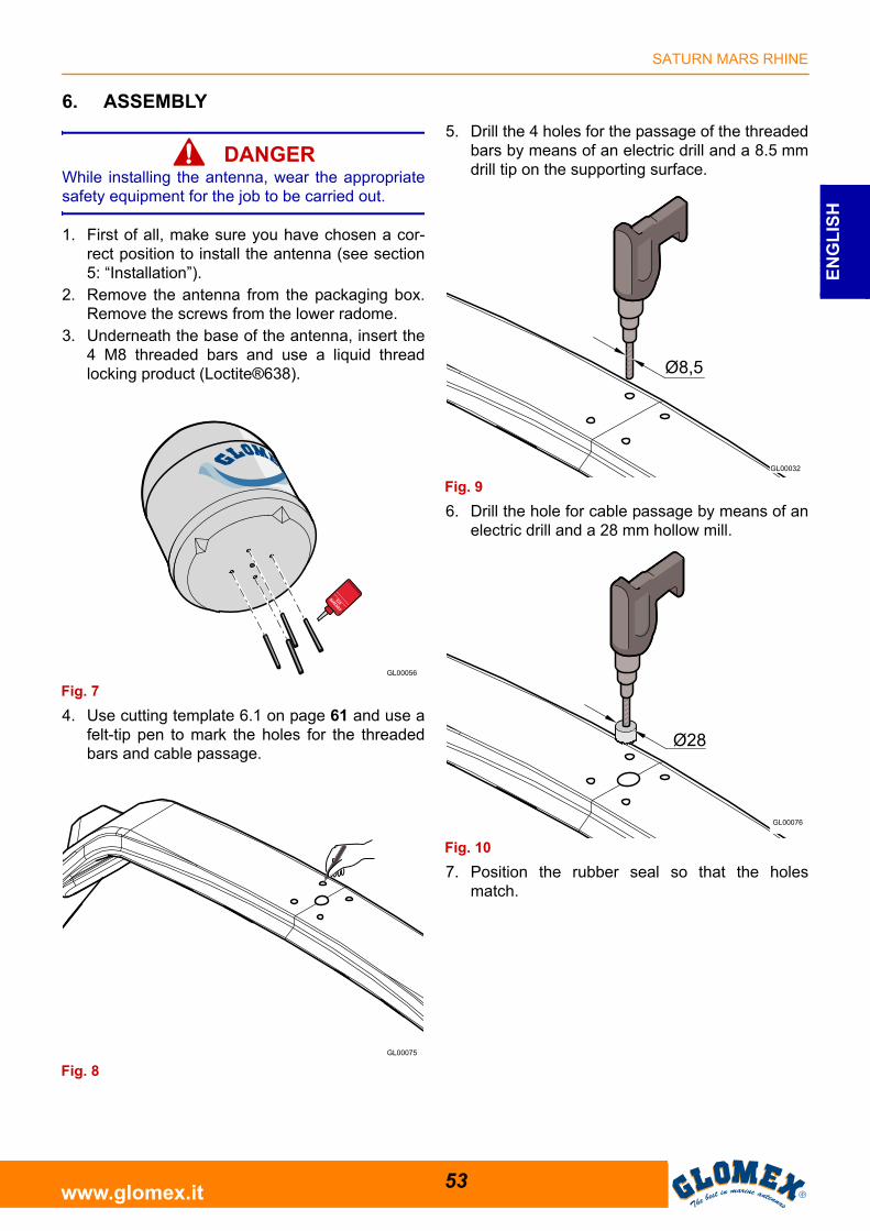
We recommend not to install the antenna at thesame level of the radar, as the radar’s energycould damage the antenna. The antenna shouldbe positioned at a distance of at least 1.5 m fromthe other transmitting antennas (VHF, radar) (Fig.6).
Fig. 6
OK NOTypical radar vertical irradiation angle
SATURN MARS RHINE
53www.glomex.it
EN
GL
ISH
6. ASSEMBLY
S DANGERWhile installing the antenna, wear the appropriatesafety equipment for the job to be carried out.
1. First of all, make sure you have chosen a cor-rect position to install the antenna (see section5: “Installation”).
2. Remove the antenna from the packaging box.Remove the screws from the lower radome.
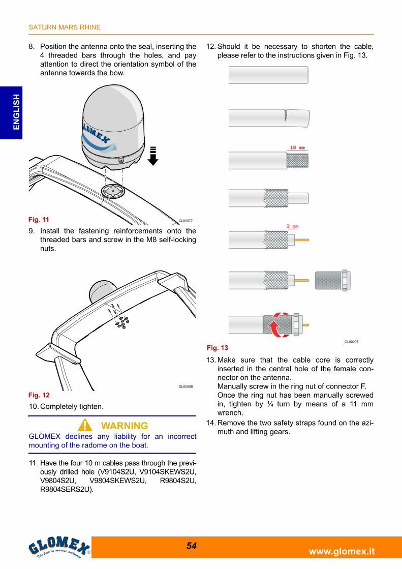
3. Underneath the base of the antenna, insert the4 M8 threaded bars and use a liquid threadlocking product (Loctite®638).
4. Use cutting template 6.1 on page 61 and use afelt-tip pen to mark the holes for the threadedbars and cable passage.
5. Drill the 4 holes for the passage of the threadedbars by means of an electric drill and a 8.5 mmdrill tip on the supporting surface.
6. Drill the hole for cable passage by means of anelectric drill and a 28 mm hollow mill.
7. Position the rubber seal so that the holesmatch.
Fig. 7
Fig. 8
Fig. 9
Fig. 10
SATURN MARS RHINE
54www.glomex.it
EN
GL
ISH
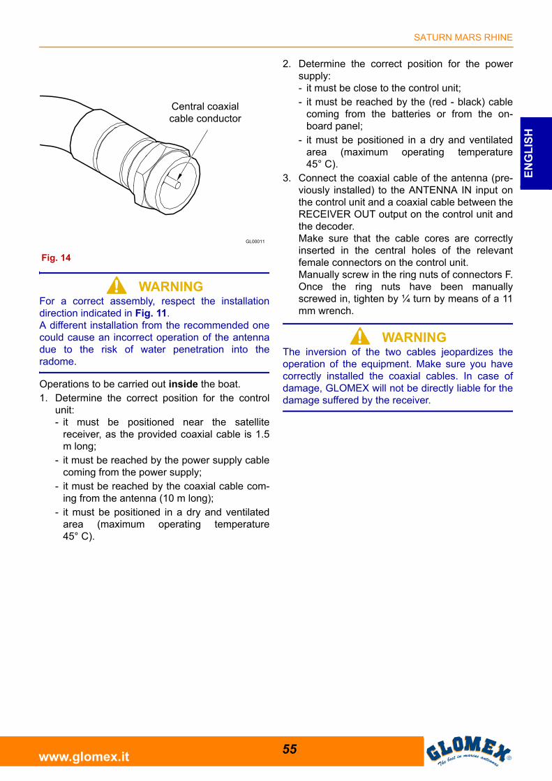
8. Position the antenna onto the seal, inserting the4 threaded bars through the holes, and payattention to direct the orientation symbol of theantenna towards the bow.
9. Install the fastening reinforcements onto thethreaded bars and screw in the M8 self-lockingnuts.
10. Completely tighten.
S WARNINGGLOMEX declines any liability for an incorrectmounting of the radome on the boat.
11. Have the four 10 m cables pass through the previ-ously drilled hole (V9104S2U, V9104SKEWS2U,V9804S2U, V9804SKEWS2U, R9804S2U,R9804SERS2U).
12. Should it be necessary to shorten the cable,please refer to the instructions given in Fig. 13.
13. Make sure that the cable core is correctlyinserted in the central hole of the female con-nector on the antenna.Manually screw in the ring nut of connector F.Once the ring nut has been manually screwedin, tighten by ¼ turn by means of a 11 mmwrench.
14. Remove the two safety straps found on the azi-muth and lifting gears.
Fig. 11
Fig. 12
GL00095
Fig. 13
SATURN MARS RHINE
55www.glomex.it
EN
GL
ISH
S WARNINGFor a correct assembly, respect the installationdirection indicated in Fig. 11.A different installation from the recommended onecould cause an incorrect operation of the antennadue to the risk of water penetration into theradome.
Operations to be carried out inside the boat.1. Determine the correct position for the control
unit:- it must be positioned near the satellite
receiver, as the provided coaxial cable is 1.5m long;
- it must be reached by the power supply cablecoming from the power supply;
- it must be reached by the coaxial cable com-ing from the antenna (10 m long);
- it must be positioned in a dry and ventilatedarea (maximum operating temperature45° C).
2. Determine the correct position for the powersupply:- it must be close to the control unit;- it must be reached by the (red - black) cable
coming from the batteries or from the on-board panel;
- it must be positioned in a dry and ventilatedarea (maximum operating temperature45° C).
3. Connect the coaxial cable of the antenna (pre-viously installed) to the ANTENNA IN input onthe control unit and a coaxial cable between theRECEIVER OUT output on the control unit andthe decoder.Make sure that the cable cores are correctlyinserted in the central holes of the relevantfemale connectors on the control unit. Manually screw in the ring nuts of connectors F.Once the ring nuts have been manuallyscrewed in, tighten by ¼ turn by means of a 11mm wrench.
S WARNINGThe inversion of the two cables jeopardizes theoperation of the equipment. Make sure you havecorrectly installed the coaxial cables. In case ofdamage, GLOMEX will not be directly liable for thedamage suffered by the receiver.
Central coaxial cable conductor
Fig. 14
SATURN MARS RHINE
56www.glomex.it
EN
GL
ISH
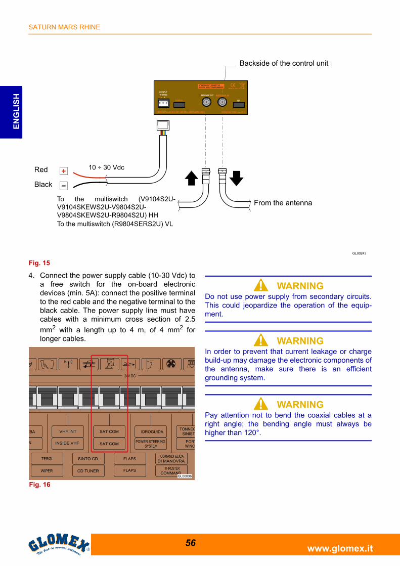
4. Connect the power supply cable (10-30 Vdc) toa free switch for the on-board electronicdevices (min. 5A): connect the positive terminalto the red cable and the negative terminal to theblack cable. The power supply line must havecables with a minimum cross section of 2.5
mm2 with a length up to 4 m, of 4 mm2 forlonger cables.
S WARNINGDo not use power supply from secondary circuits.This could jeopardize the operation of the equip-ment.
S WARNINGIn order to prevent that current leakage or chargebuild-up may damage the electronic components ofthe antenna, make sure there is an efficientgrounding system.
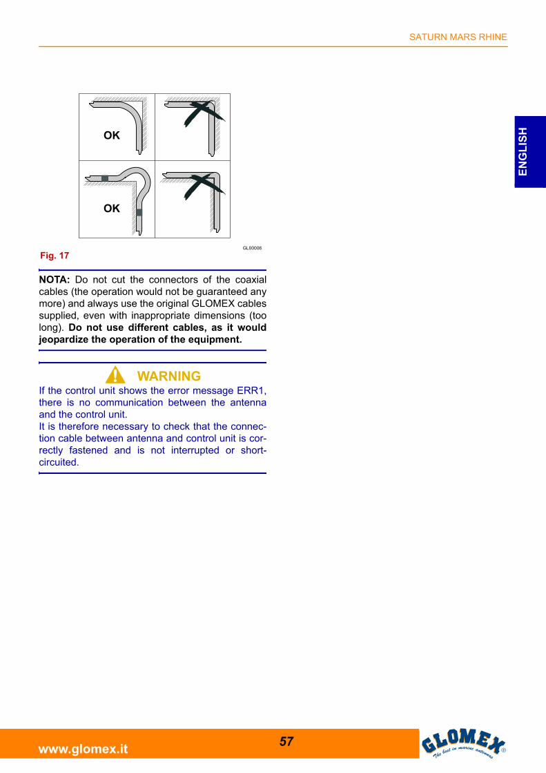
S WARNINGPay attention not to bend the coaxial cables at aright angle; the bending angle must always behigher than 120°.
Fig. 15
Backside of the control unit
From the antennaTo the multiswitch (V9104S2U-V9104SKEWS2U-V9804S2U-V9804SKEWS2U-R9804S2U) HHTo the multiswitch (R9804SERS2U) VL
Red
Black
10 ÷ 30 Vdc
Fig. 16
SATURN MARS RHINE
57www.glomex.it
EN
GL
ISH
NOTA: Do not cut the connectors of the coaxialcables (the operation would not be guaranteed anymore) and always use the original GLOMEX cablessupplied, even with inappropriate dimensions (toolong). Do not use different cables, as it wouldjeopardize the operation of the equipment.
S WARNINGIf the control unit shows the error message ERR1,there is no communication between the antennaand the control unit.It is therefore necessary to check that the connec-tion cable between antenna and control unit is cor-rectly fastened and is not interrupted or short-circuited.
Fig. 17
SATURN MARS RHINE
58www.glomex.it
EN
GL
ISH
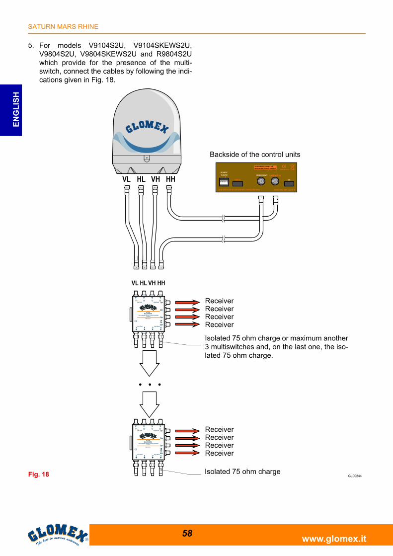
5. For models V9104S2U, V9104SKEWS2U,V9804S2U, V9804SKEWS2U and R9804S2Uwhich provide for the presence of the multi-switch, connect the cables by following the indi-cations given in Fig. 18.
Fig. 18
Backside of the control units
ReceiverReceiverReceiverReceiver
Isolated 75 ohm charge or maximum another3 multiswitches and, on the last one, the iso-lated 75 ohm charge.
Isolated 75 ohm charge
ReceiverReceiverReceiverReceiver
SATURN MARS RHINE
59www.glomex.it
EN
GL
ISH
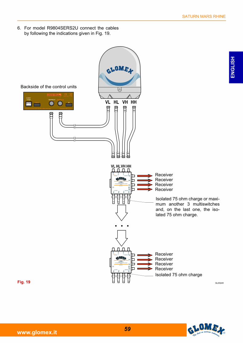
6. For model R9804SERS2U connect the cablesby following the indications given in Fig. 19.
Fig. 19
Backside of the control units
Isolated 75 ohm charge or maxi-mum another 3 multiswitchesand, on the last one, the iso-lated 75 ohm charge.
Isolated 75 ohm charge
ReceiverReceiverReceiverReceiver
ReceiverReceiverReceiverReceiver
SATURN MARS RHINE
60www.glomex.it
EN
GL
ISH
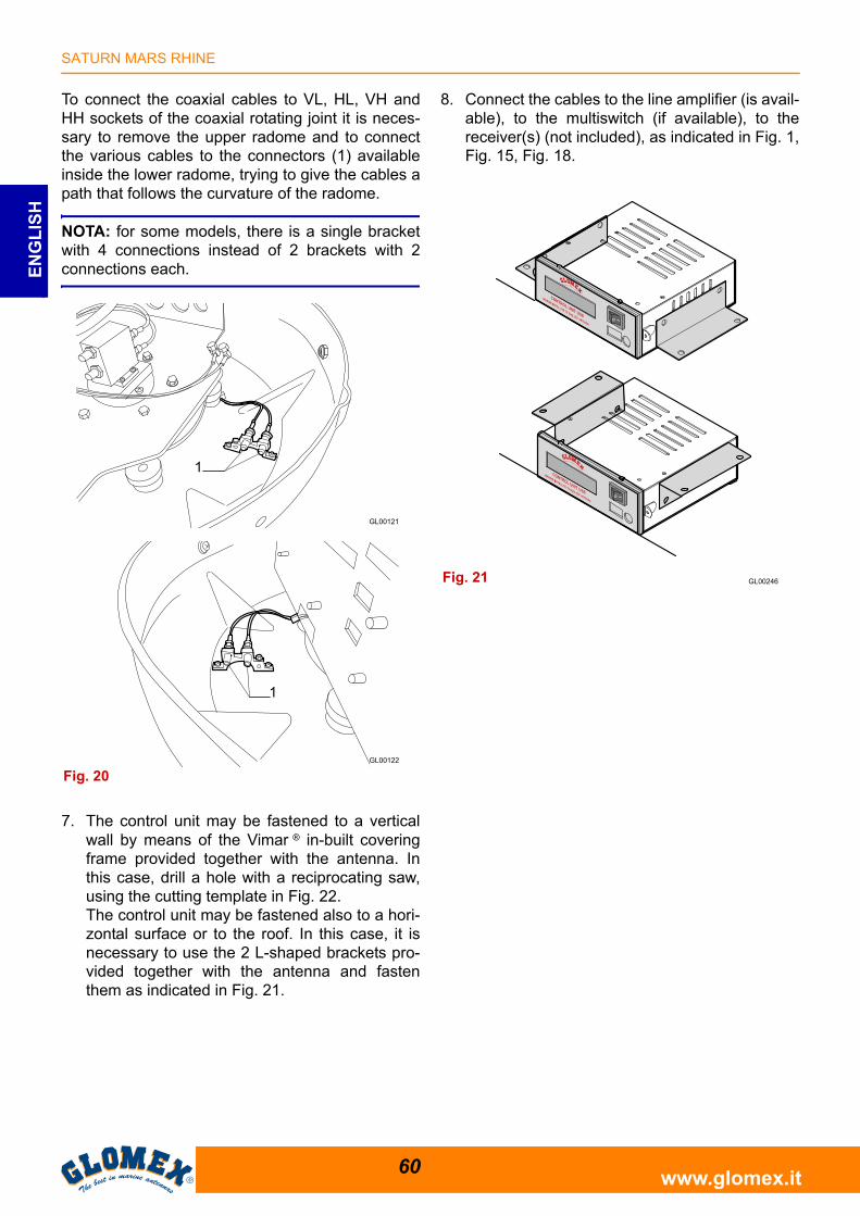
To connect the coaxial cables to VL, HL, VH andHH sockets of the coaxial rotating joint it is neces-sary to remove the upper radome and to connectthe various cables to the connectors (1) availableinside the lower radome, trying to give the cables apath that follows the curvature of the radome.
NOTA: for some models, there is a single bracketwith 4 connections instead of 2 brackets with 2connections each.
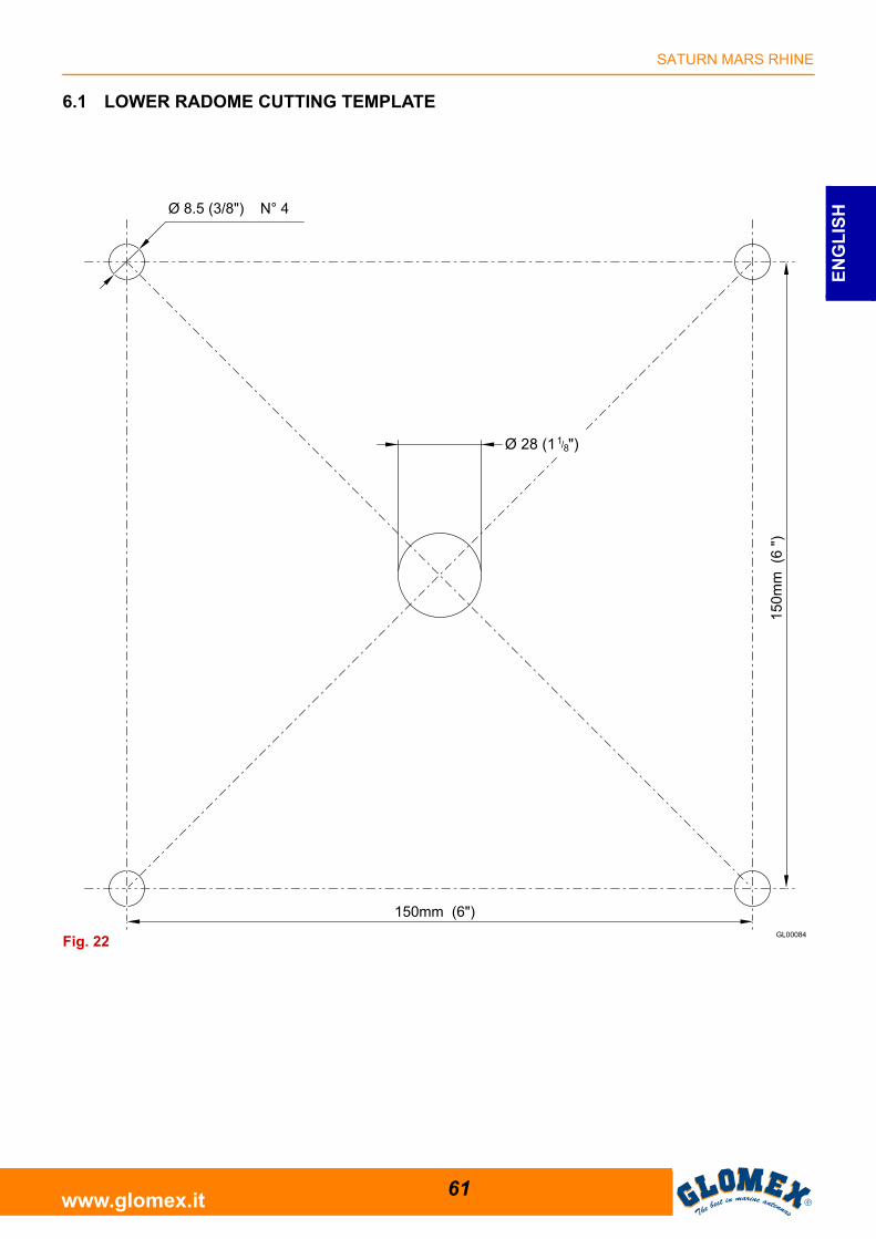
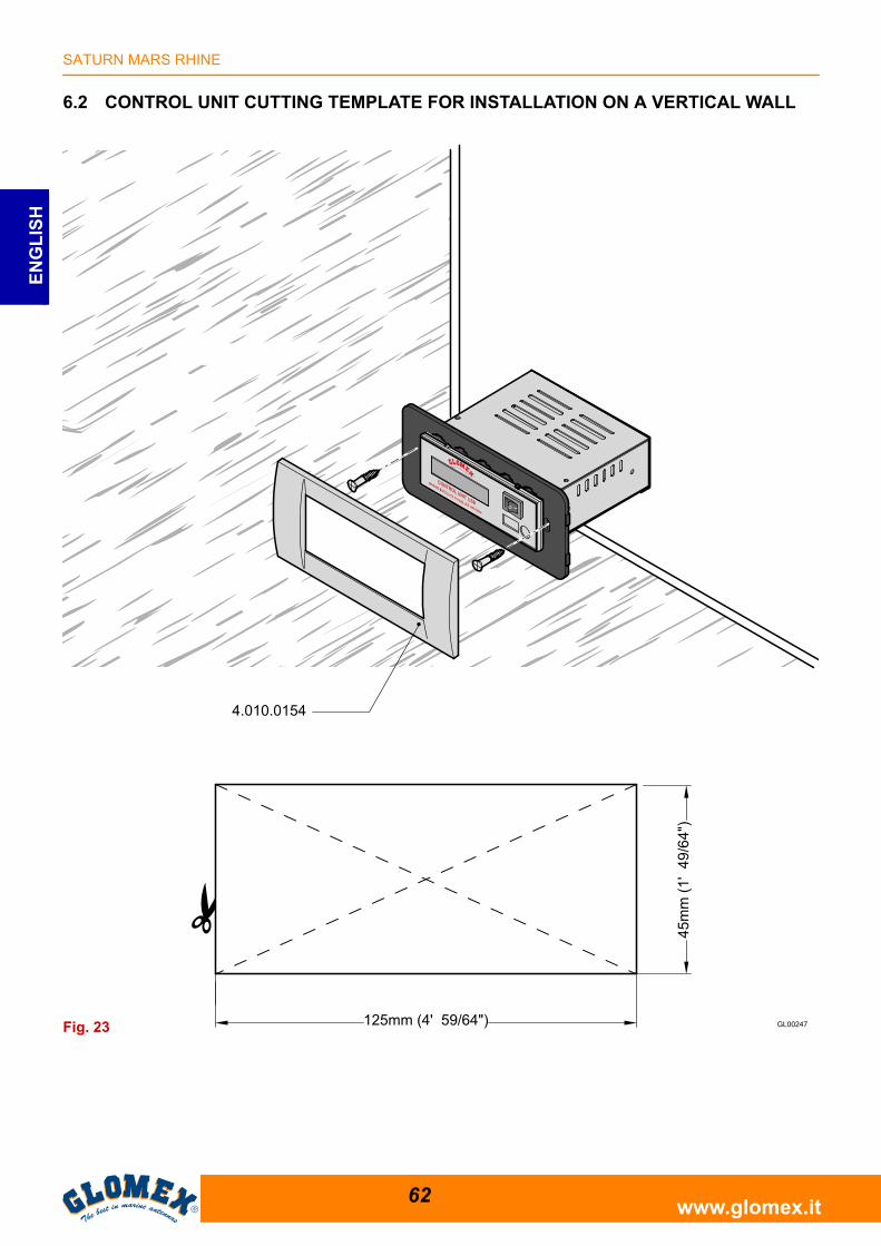
7. The control unit may be fastened to a verticalwall by means of the Vimar ® in-built coveringframe provided together with the antenna. Inthis case, drill a hole with a reciprocating saw,using the cutting template in Fig. 22.The control unit may be fastened also to a hori-zontal surface or to the roof. In this case, it isnecessary to use the 2 L-shaped brackets pro-vided together with the antenna and fastenthem as indicated in Fig. 21.
8. Connect the cables to the line amplifier (is avail-able), to the multiswitch (if available), to thereceiver(s) (not included), as indicated in Fig. 1,Fig. 15, Fig. 18.
Fig. 20
Fig. 21
SATURN MARS RHINE
61www.glomex.it
EN
GL
ISH
6.1 LOWER RADOME CUTTING TEMPLATE
Fig. 22
SATURN MARS RHINE
62www.glomex.it
EN
GL
ISH
6.2 CONTROL UNIT CUTTING TEMPLATE FOR INSTALLATION ON A VERTICAL WALL
Fig. 23
SATURN MARS RHINE
63www.glomex.it
EN
GL
ISH
6.3 SKEW CALIBRATION (MANUAL)
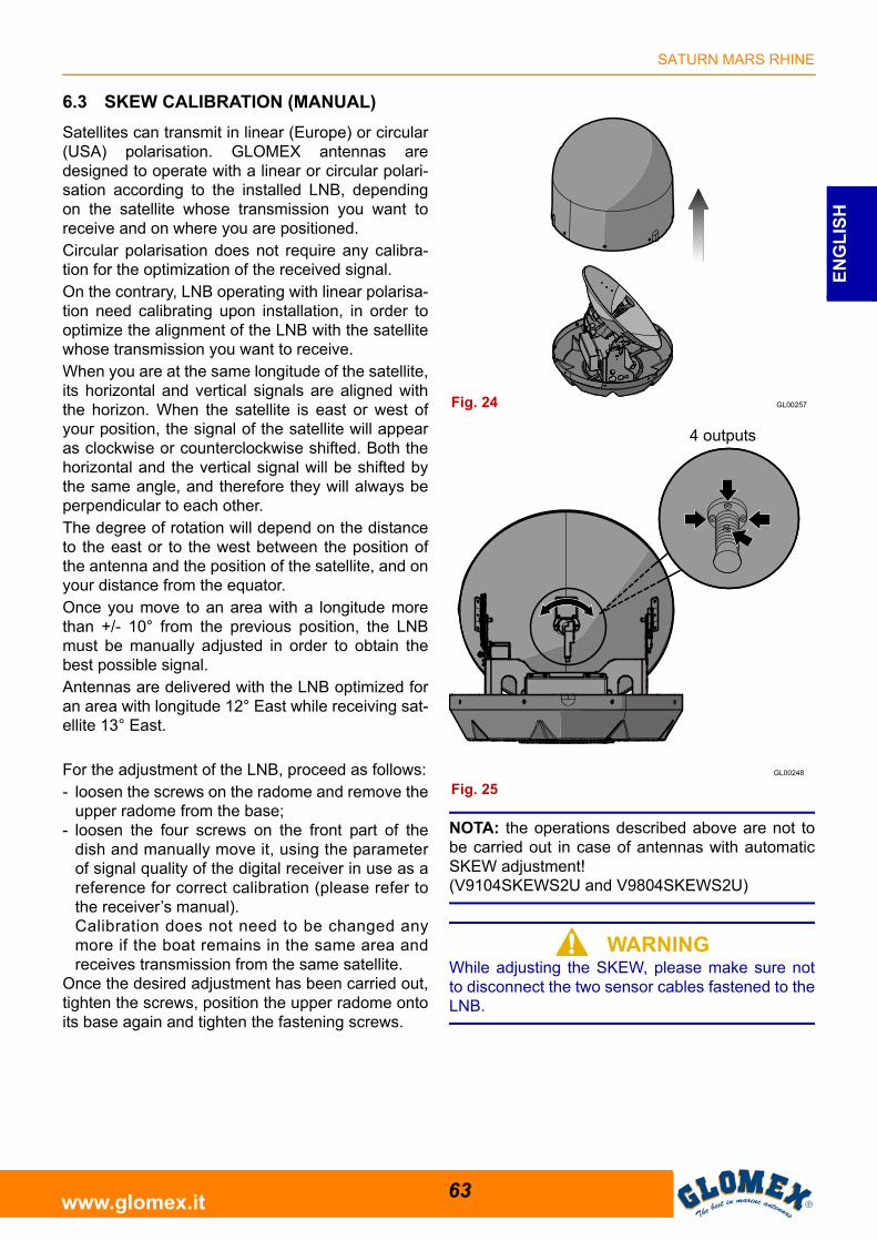
Satellites can transmit in linear (Europe) or circular(USA) polarisation. GLOMEX antennas aredesigned to operate with a linear or circular polari-sation according to the installed LNB, dependingon the satellite whose transmission you want toreceive and on where you are positioned.Circular polarisation does not require any calibra-tion for the optimization of the received signal.On the contrary, LNB operating with linear polarisa-tion need calibrating upon installation, in order tooptimize the alignment of the LNB with the satellitewhose transmission you want to receive.When you are at the same longitude of the satellite,its horizontal and vertical signals are aligned withthe horizon. When the satellite is east or west ofyour position, the signal of the satellite will appearas clockwise or counterclockwise shifted. Both thehorizontal and the vertical signal will be shifted bythe same angle, and therefore they will always beperpendicular to each other.The degree of rotation will depend on the distanceto the east or to the west between the position ofthe antenna and the position of the satellite, and onyour distance from the equator.Once you move to an area with a longitude morethan +/- 10° from the previous position, the LNBmust be manually adjusted in order to obtain thebest possible signal.Antennas are delivered with the LNB optimized foran area with longitude 12° East while receiving sat-ellite 13° East.
For the adjustment of the LNB, proceed as follows:- loosen the screws on the radome and remove the
upper radome from the base;- loosen the four screws on the front part of the
dish and manually move it, using the parameterof signal quality of the digital receiver in use as areference for correct calibration (please refer tothe receiver’s manual). Calibration does not need to be changed anymore if the boat remains in the same area andreceives transmission from the same satellite.
Once the desired adjustment has been carried out,tighten the screws, position the upper radome ontoits base again and tighten the fastening screws.
NOTA: the operations described above are not tobe carried out in case of antennas with automaticSKEW adjustment!(V9104SKEWS2U and V9804SKEWS2U)
S WARNINGWhile adjusting the SKEW, please make sure notto disconnect the two sensor cables fastened to theLNB.
Fig. 24
Fig. 25
4 outputs
SATURN MARS RHINE
64www.glomex.it
EN
GL
ISH
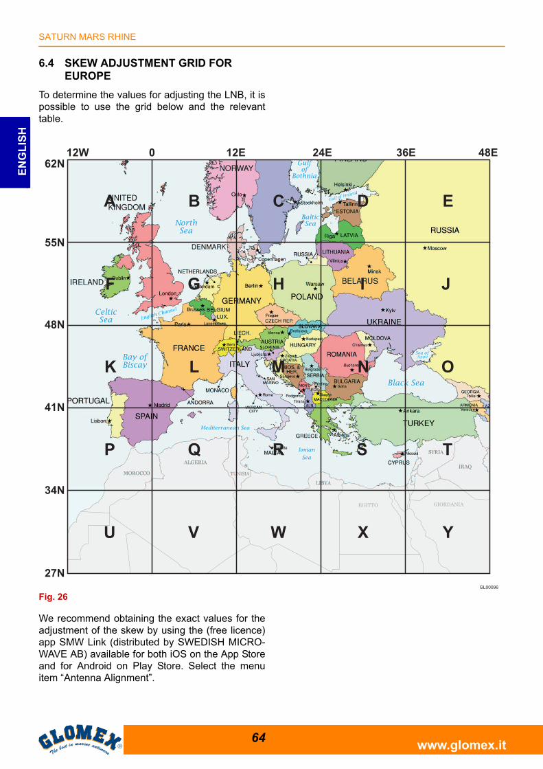
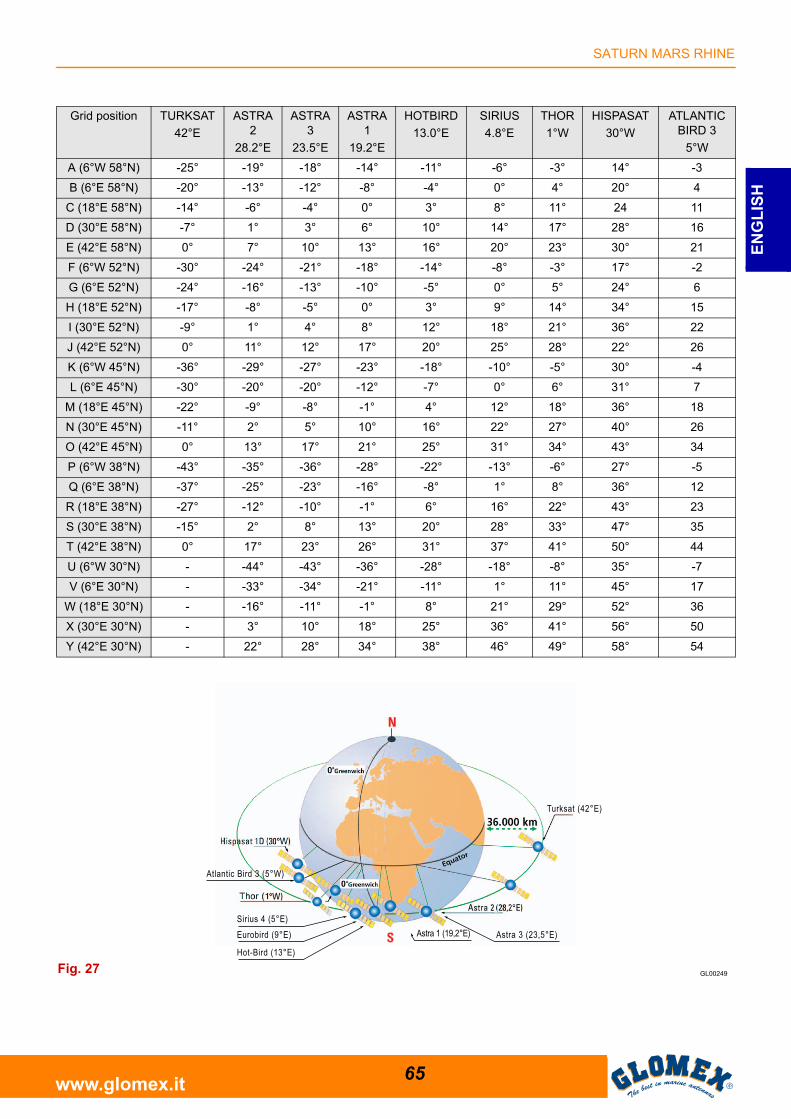
6.4 SKEW ADJUSTMENT GRID FOR EUROPE
To determine the values for adjusting the LNB, it ispossible to use the grid below and the relevanttable.
We recommend obtaining the exact values for theadjustment of the skew by using the (free licence)app SMW Link (distributed by SWEDISH MICRO-WAVE AB) available for both iOS on the App Storeand for Android on Play Store. Select the menuitem “Antenna Alignment”.
EGITTO GIORDANIA
GL00096
Fig. 26
SATURN MARS RHINE
65www.glomex.it
EN
GL
ISH
Grid position TURKSAT
42°E
ASTRA2
28.2°E
ASTRA3
23.5°E
ASTRA1
19.2°E
HOTBIRD
13.0°E
SIRIUS
4.8°E
THOR
1°W
HISPASAT
30°W
ATLANTIC BIRD 3
5°W
A (6°W 58°N) -25° -19° -18° -14° -11° -6° -3° 14° -3
B (6°E 58°N) -20° -13° -12° -8° -4° 0° 4° 20° 4
C (18°E 58°N) -14° -6° -4° 0° 3° 8° 11° 24 11
D (30°E 58°N) -7° 1° 3° 6° 10° 14° 17° 28° 16
E (42°E 58°N) 0° 7° 10° 13° 16° 20° 23° 30° 21
F (6°W 52°N) -30° -24° -21° -18° -14° -8° -3° 17° -2
G (6°E 52°N) -24° -16° -13° -10° -5° 0° 5° 24° 6
H (18°E 52°N) -17° -8° -5° 0° 3° 9° 14° 34° 15
I (30°E 52°N) -9° 1° 4° 8° 12° 18° 21° 36° 22
J (42°E 52°N) 0° 11° 12° 17° 20° 25° 28° 22° 26
K (6°W 45°N) -36° -29° -27° -23° -18° -10° -5° 30° -4
L (6°E 45°N) -30° -20° -20° -12° -7° 0° 6° 31° 7
M (18°E 45°N) -22° -9° -8° -1° 4° 12° 18° 36° 18
N (30°E 45°N) -11° 2° 5° 10° 16° 22° 27° 40° 26
O (42°E 45°N) 0° 13° 17° 21° 25° 31° 34° 43° 34
P (6°W 38°N) -43° -35° -36° -28° -22° -13° -6° 27° -5
Q (6°E 38°N) -37° -25° -23° -16° -8° 1° 8° 36° 12
R (18°E 38°N) -27° -12° -10° -1° 6° 16° 22° 43° 23
S (30°E 38°N) -15° 2° 8° 13° 20° 28° 33° 47° 35
T (42°E 38°N) 0° 17° 23° 26° 31° 37° 41° 50° 44
U (6°W 30°N) - -44° -43° -36° -28° -18° -8° 35° -7
V (6°E 30°N) - -33° -34° -21° -11° 1° 11° 45° 17
W (18°E 30°N) - -16° -11° -1° 8° 21° 29° 52° 36
X (30°E 30°N) - 3° 10° 18° 25° 36° 41° 56° 50
Y (42°E 30°N) - 22° 28° 34° 38° 46° 49° 58° 54
Astra 3 (23,5°E)
Turksat (42°E)
Eurobird (9°E)
Hot-Bird (13°E)
Sirius 4 (5°E)Astra 1 (19,2°E)
Atlantic Bird 3 (5°W)
GL00249Fig. 27
SATURN MARS RHINE
66www.glomex.it
EN
GL
ISH
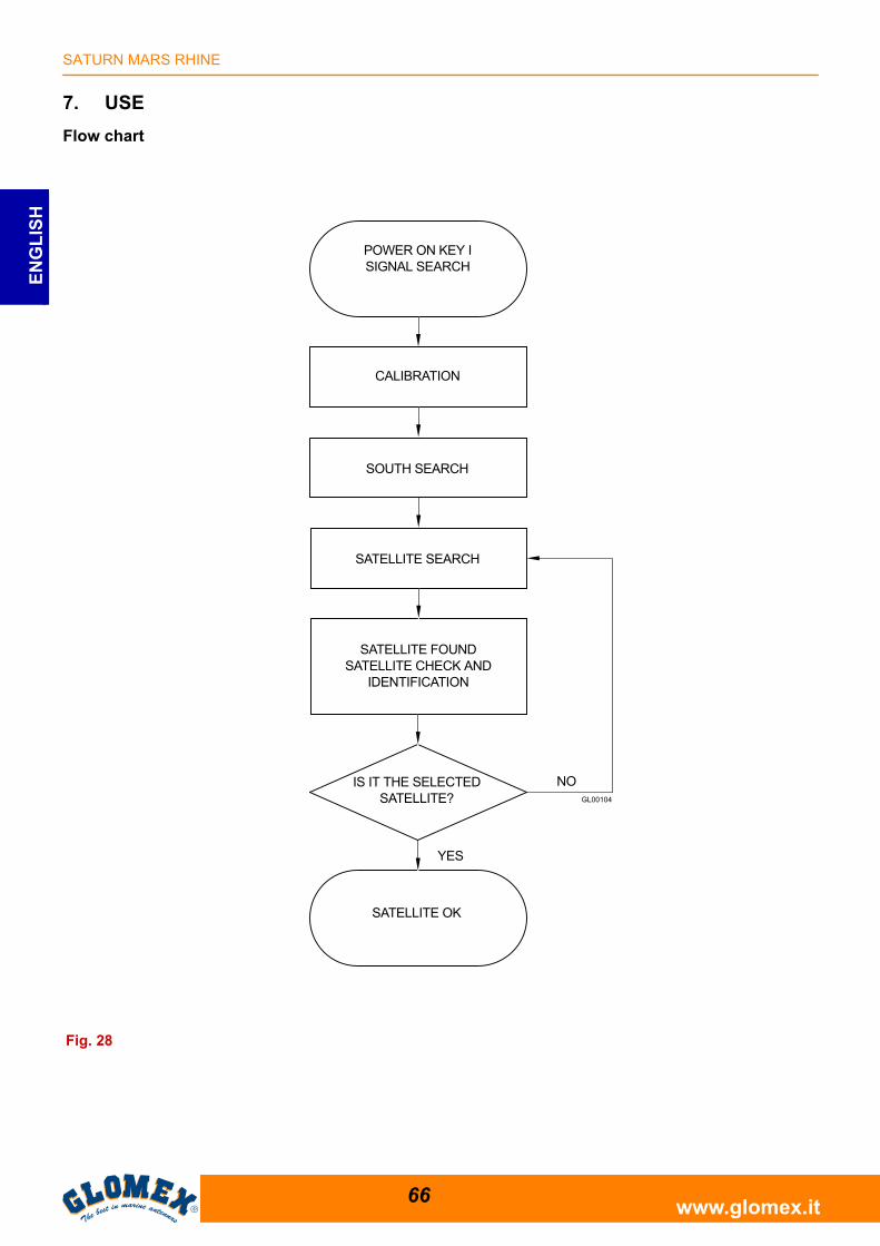
7. USE
Flow chart
Fig. 28
POWER ON KEY ISIGNAL SEARCH
SOUTH SEARCH
IS IT THE SELECTED SATELLITE?
NO
SATELLITE SEARCH
SATELLITE OK
YES
CALIBRATION
SATELLITE FOUNDSATELLITE CHECK AND
IDENTIFICATION
SATURN MARS RHINE
67www.glomex.it
EN
GL
ISH
1. Make sure that the antenna has a clear view ofthe sky in order to receive satellite signals.
2. Turn on the receiver and the TV set. For detailsabout the use of the receiver and the TV set,please refer to the relevant user manuals pro-vided by the manufacturers.
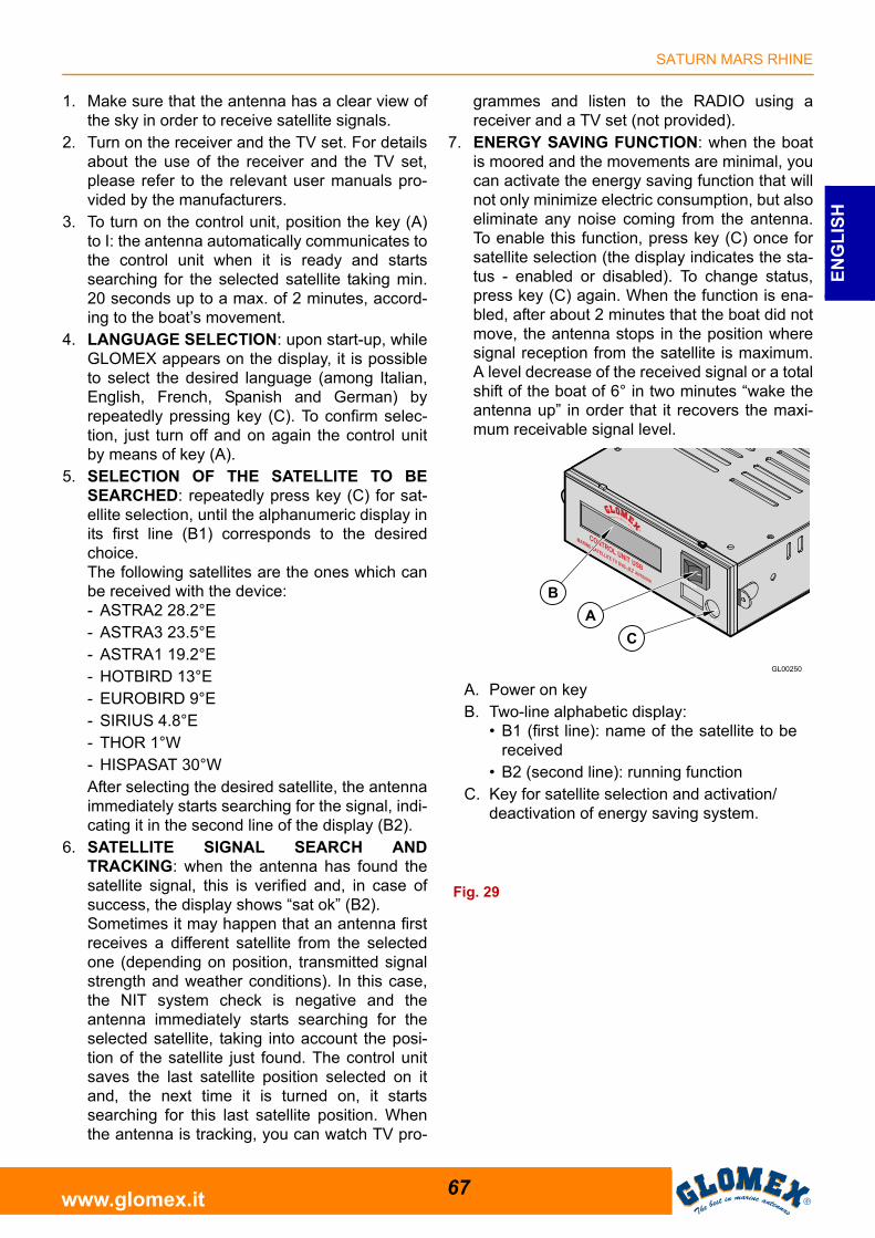
3. To turn on the control unit, position the key (A)to I: the antenna automatically communicates tothe control unit when it is ready and startssearching for the selected satellite taking min.20 seconds up to a max. of 2 minutes, accord-ing to the boat’s movement.
4. LANGUAGE SELECTION: upon start-up, whileGLOMEX appears on the display, it is possibleto select the desired language (among Italian,English, French, Spanish and German) byrepeatedly pressing key (C). To confirm selec-tion, just turn off and on again the control unitby means of key (A).
5. SELECTION OF THE SATELLITE TO BESEARCHED: repeatedly press key (C) for sat-ellite selection, until the alphanumeric display inits first line (B1) corresponds to the desiredchoice.The following satellites are the ones which canbe received with the device:- ASTRA2 28.2°E- ASTRA3 23.5°E- ASTRA1 19.2°E- HOTBIRD 13°E- EUROBIRD 9°E- SIRIUS 4.8°E- THOR 1°W- HISPASAT 30°WAfter selecting the desired satellite, the antennaimmediately starts searching for the signal, indi-cating it in the second line of the display (B2).
6. SATELLITE SIGNAL SEARCH ANDTRACKING: when the antenna has found thesatellite signal, this is verified and, in case ofsuccess, the display shows “sat ok” (B2).Sometimes it may happen that an antenna firstreceives a different satellite from the selectedone (depending on position, transmitted signalstrength and weather conditions). In this case,the NIT system check is negative and theantenna immediately starts searching for theselected satellite, taking into account the posi-tion of the satellite just found. The control unitsaves the last satellite position selected on itand, the next time it is turned on, it startssearching for this last satellite position. Whenthe antenna is tracking, you can watch TV pro-
grammes and listen to the RADIO using areceiver and a TV set (not provided).
7. ENERGY SAVING FUNCTION: when the boatis moored and the movements are minimal, youcan activate the energy saving function that willnot only minimize electric consumption, but alsoeliminate any noise coming from the antenna.To enable this function, press key (C) once forsatellite selection (the display indicates the sta-tus - enabled or disabled). To change status,press key (C) again. When the function is ena-bled, after about 2 minutes that the boat did notmove, the antenna stops in the position wheresignal reception from the satellite is maximum.A level decrease of the received signal or a totalshift of the boat of 6° in two minutes “wake theantenna up” in order that it recovers the maxi-mum receivable signal level.
Fig. 29
A. Power on keyB. Two-line alphabetic display:
• B1 (first line): name of the satellite to bereceived
• B2 (second line): running functionC. Key for satellite selection and activation/
deactivation of energy saving system.
SATURN MARS RHINE
68www.glomex.it
EN
GL
ISH
CAPTION OF CONTROL UNIT FUNCTIONSStart-up: when turning on the control unit, the dis-play shows‘ GLOMEX V9804S2U ’‘ DVB-S2 VX.XXX ’VX.XXX = SW VERSIONANTENNA INIT: in this phase, the antenna posi-tions itself for calibration;CALIBRATION: calibration phase of the gyro-scopes;SOUTH SEARCH: rotation of the azimuth axiswhich positions the antenna southbound;SAT SEARCH: satellite search; unless the userintervenes, the antenna automatically startssearching for the last satellite received;FOUND SAT: writing that appears on the displaywhen the antenna finds a satellite signal before theNIT system check is run.LOST SIGNAL: it appears in case the signal is lost;ANT. STANDBY: it appears when the antennamanages to receive the satellite signal and the boatremains motionless for a certain period of time. Inthis situation, the antenna stops on the maximumvalue of the received signal, reducing operatingnoise and energy consumption;NEXT SAT SEARCH: message displayed whenthe antenna passes from one satellite to another,when the first satellite received does not match theone selected;SAT VERIFICATION: message that appears whenthe satellite is received during the NIT system veri-fication phase;WARNING ERR 1: there is no communicationbetween the antenna and the control unit.SAT OK: it indicates that the selected satellite hasbeen correctly hooked up and verified.READY FOR UPDATE - INSERT USB KEY: await-ing the USB memory containing the upgrade file.CHECK UPGRADE FILE: check of the upgradefile.UPDATING: upgrade in progress.UPGRADE SUCCESSFUL: upgrade executedsuccessfully.
SATURN MARS RHINE
69www.glomex.it
EN
GL
ISH
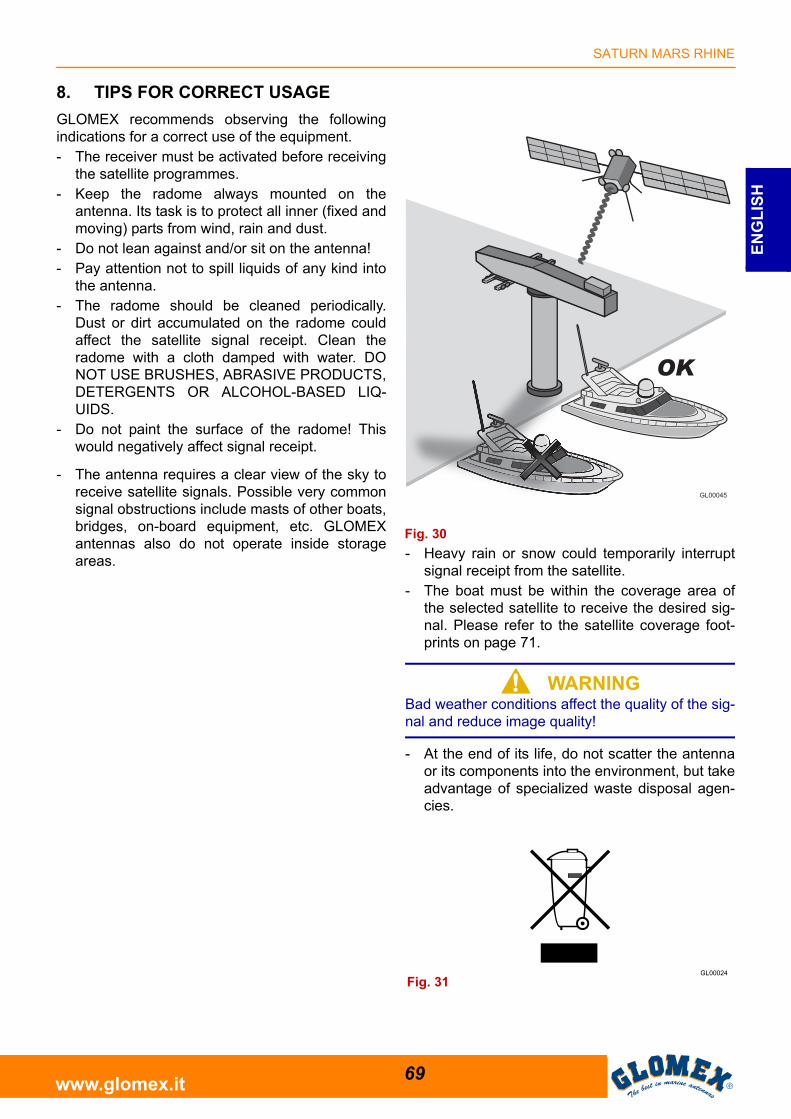
8. TIPS FOR CORRECT USAGE
GLOMEX recommends observing the followingindications for a correct use of the equipment.- The receiver must be activated before receiving
the satellite programmes.- Keep the radome always mounted on the
antenna. Its task is to protect all inner (fixed andmoving) parts from wind, rain and dust.
- Do not lean against and/or sit on the antenna!- Pay attention not to spill liquids of any kind into
the antenna.- The radome should be cleaned periodically.
Dust or dirt accumulated on the radome couldaffect the satellite signal receipt. Clean theradome with a cloth damped with water. DONOT USE BRUSHES, ABRASIVE PRODUCTS,DETERGENTS OR ALCOHOL-BASED LIQ-UIDS.
- Do not paint the surface of the radome! Thiswould negatively affect signal receipt.
- The antenna requires a clear view of the sky toreceive satellite signals. Possible very commonsignal obstructions include masts of other boats,bridges, on-board equipment, etc. GLOMEXantennas also do not operate inside storageareas. - Heavy rain or snow could temporarily interrupt
signal receipt from the satellite.- The boat must be within the coverage area of
the selected satellite to receive the desired sig-nal. Please refer to the satellite coverage foot-prints on page 71.
S WARNINGBad weather conditions affect the quality of the sig-nal and reduce image quality!
- At the end of its life, do not scatter the antennaor its components into the environment, but takeadvantage of specialized waste disposal agen-cies.
GL00045
Fig. 30
Fig. 31
SATURN MARS RHINE
70www.glomex.it
EN
GL
ISH
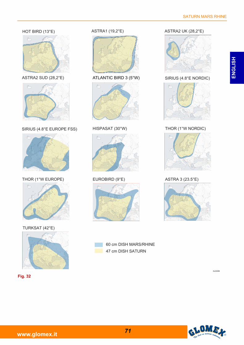
8.1 FOOTPRINTS: SATELLITE TRANSMISSION AREAS
Satellite television is one of the few means whichallow receiving information in any part of the worldwithin the coverage area of the satellite you wish toreceive.The signal transmitted by the satellite generally hasa wide coverage area, as shown in the purely indic-ative footprints on the following page, and thusguarantees you can watch the same TV pro-grammes in various areas.However, it is important to remember that groundobstacles are the main causes of satellite antennamalfunction.Ground obstacles include all bodies which could belocated between satellite and antenna, such asmasts of other boats, bridges, on-board equipment,etc.The signal transmitted by the satellite is alsoaffected by weather conditions (storm clouds or iceclouds).The footprints show the satellite coverage areas onthe Earth by using the GLOMEX satellite antennas.
S WARNINGIn case of bad weather, signals will be weaker;therefore, the image quality could be reduced, upto completely fading away. It is also very importantto make sure, upon purchase, that the dimensionsof the satellite antenna are the most appropriateones to receive the signal in the areas where youspend your holiday. Footprints are indicative andreferred to the satellite with the strongest E.I.R.P.(Equivalent Isotropic Radiated Power).
SATURN MARS RHINE
71www.glomex.it
EN
GL
ISH
GL00258
ATLANTIC BIRD 3 (5°W)
Fig. 32
SATURN MARS RHINE
72www.glomex.it
EN
GL
ISH
9. MAINTENANCE
9.1 PREVENTIVE MAINTENANCE
GLOMEX antennas require minimum preventivemaintenance.Observing the following instructions is sufficient tomaintain a high equipment performance.
Monthly checks- Wash the radome surface with a cloth damped
with fresh water; do not direct pressurized waterjets onto the radome.
S WARNINGDo not use brushes, abrasive products, detergentsor alcohol-based liquids.
Yearly checks- Check the outer conditions of the radome. Clean
from dust and dirt if necessary.
Checks before any long cruise- Check that the antenna is correctly fastened.
S DANGERBefore carrying out any maintenance or cleaningoperation, or after each use, ALWAYS turn off theantenna by means of the switch located on thecontrol unit or from the on-board control panel.
Should you have problems with the operation or incase you need technical support, first of all contactthe authorized Retailer. Keep at hand the serialnumber of your antenna (on page 2 in this manual)and a list with the failure symptoms. Should noRetailer be available, contact the GLOMEX ServiceCentre (see section “Technical Support”).
S WARNINGYou will be asked the serial number of yourantenna during any service or troubleshootingphone call. The serial number is found on page 2 ofthe user manual of your antenna (see page 44 forserial number indications).
S WARNINGConserve the installation and user manual withcare, as it contains the serial number of yourantenna!
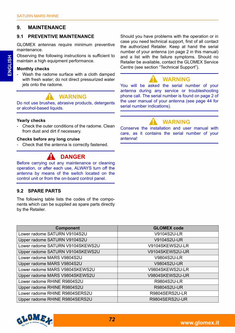
9.2 SPARE PARTS
The following table lists the codes of the compo-nents which can be supplied as spare parts directlyby the Retailer.
Component GLOMEX codeLower radome SATURN V9104S2U V9104S2U-LRUpper radome SATURN V9104S2U V9104S2U-URLower radome SATURN V9104SKEWS2U V9104SKEWS2U-LRUpper radome SATURN V9104SKEWS2U V9104SKEWS2U-URLower radome MARS V9804S2U V9804S2U-LRUpper radome MARS V9804S2U V9804S2U-URLower radome MARS V9804SKEWS2U V9804SKEWS2U-LRUpper radome MARS V9804SKEWS2U V9804SKEWS2U-URLower radome RHINE R9804S2U R9804S2U-LRUpper radome RHINE R9804S2U R9804S2U-URLower radome RHINE R9804SERS2U R9804SERS2U-LRUpper radome RHINE R9804SERS2U R9804SERS2U-UR
SATURN MARS RHINE
73www.glomex.it
EN
GL
ISH
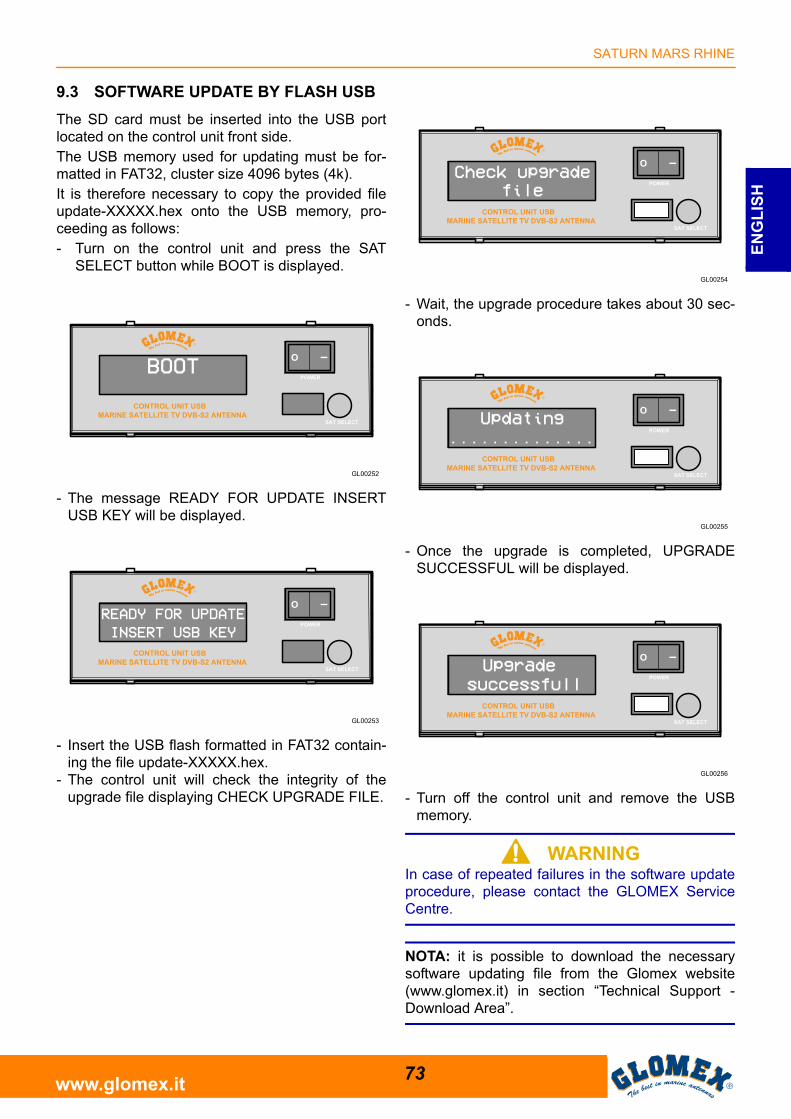
9.3 SOFTWARE UPDATE BY FLASH USB
The SD card must be inserted into the USB portlocated on the control unit front side.The USB memory used for updating must be for-matted in FAT32, cluster size 4096 bytes (4k).It is therefore necessary to copy the provided fileupdate-XXXXX.hex onto the USB memory, pro-ceeding as follows:- Turn on the control unit and press the SAT
SELECT button while BOOT is displayed.
- The message READY FOR UPDATE INSERTUSB KEY will be displayed.
- Insert the USB flash formatted in FAT32 contain-ing the file update-XXXXX.hex.
- The control unit will check the integrity of theupgrade file displaying CHECK UPGRADE FILE.
- Wait, the upgrade procedure takes about 30 sec-onds.
- Once the upgrade is completed, UPGRADESUCCESSFUL will be displayed.
- Turn off the control unit and remove the USBmemory.
S WARNINGIn case of repeated failures in the software updateprocedure, please contact the GLOMEX ServiceCentre.
NOTA: it is possible to download the necessarysoftware updating file from the Glomex website(www.glomex.it) in section “Technical Support -Download Area”.
SATURN MARS RHINE
74www.glomex.it
EN
GL
ISH
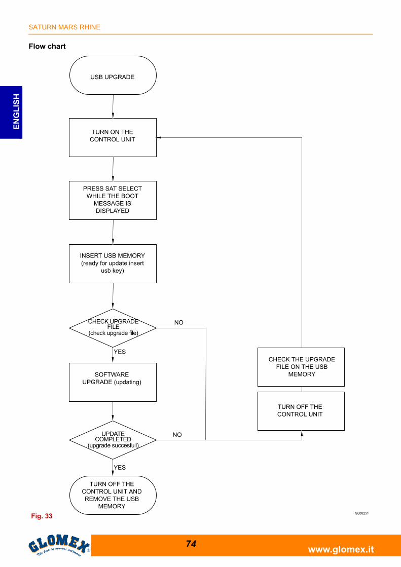
Flow chart
Fig. 33
USB UPGRADE
INSERT USB MEMORY (ready for update insert
usb key)
CHECK UPGRADE FILE
(check upgrade file)
NO
SOFTWARE UPGRADE (updating)
YES
UPDATE COMPLETED
(upgrade succesfull)
TURN OFF THE CONTROL UNIT AND REMOVE THE USB
MEMORY
NO
YES
CHECK THE UPGRADE FILE ON THE USB
MEMORY
TURN OFF THE CONTROL UNIT
PRESS SAT SELECT WHILE THE BOOT
MESSAGE IS DISPLAYED
TURN ON THE CONTROL UNIT
SATURN MARS RHINE
75www.glomex.it
EN
GL
ISH
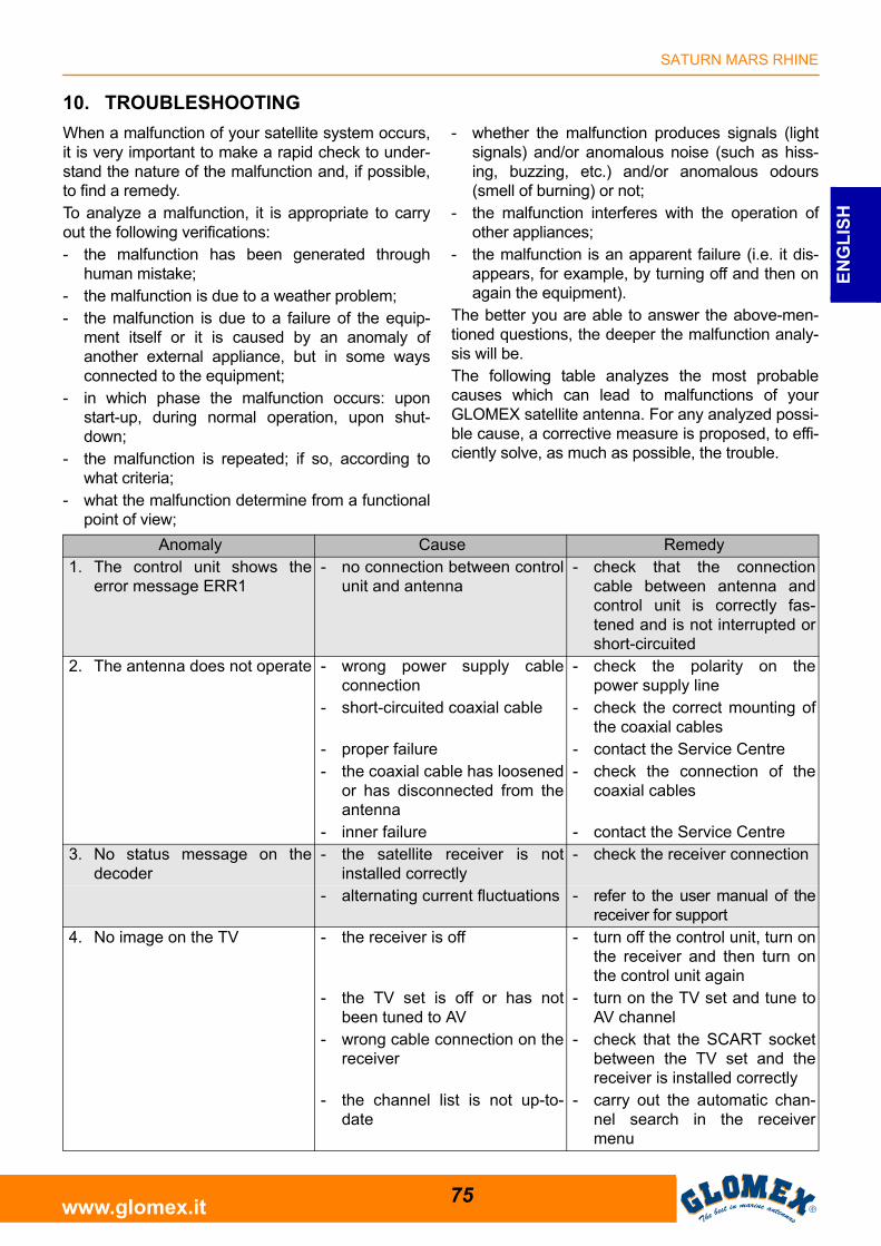
10. TROUBLESHOOTING
When a malfunction of your satellite system occurs,it is very important to make a rapid check to under-stand the nature of the malfunction and, if possible,to find a remedy.To analyze a malfunction, it is appropriate to carryout the following verifications:- the malfunction has been generated through
human mistake;- the malfunction is due to a weather problem;- the malfunction is due to a failure of the equip-
ment itself or it is caused by an anomaly ofanother external appliance, but in some waysconnected to the equipment;
- in which phase the malfunction occurs: uponstart-up, during normal operation, upon shut-down;
- the malfunction is repeated; if so, according towhat criteria;
- what the malfunction determine from a functionalpoint of view;
- whether the malfunction produces signals (lightsignals) and/or anomalous noise (such as hiss-ing, buzzing, etc.) and/or anomalous odours(smell of burning) or not;
- the malfunction interferes with the operation ofother appliances;
- the malfunction is an apparent failure (i.e. it dis-appears, for example, by turning off and then onagain the equipment).
The better you are able to answer the above-men-tioned questions, the deeper the malfunction analy-sis will be.The following table analyzes the most probablecauses which can lead to malfunctions of yourGLOMEX satellite antenna. For any analyzed possi-ble cause, a corrective measure is proposed, to effi-ciently solve, as much as possible, the trouble.
Anomaly Cause Remedy1. The control unit shows the
error message ERR1- no connection between control
unit and antenna- check that the connection
cable between antenna andcontrol unit is correctly fas-tened and is not interrupted orshort-circuited
2. The antenna does not operate - wrong power supply cableconnection
- check the polarity on thepower supply line
- short-circuited coaxial cable - check the correct mounting ofthe coaxial cables
- proper failure - contact the Service Centre- the coaxial cable has loosened
or has disconnected from theantenna
- check the connection of thecoaxial cables
- inner failure - contact the Service Centre3. No status message on the
decoder- the satellite receiver is not
installed correctly- check the receiver connection
- alternating current fluctuations - refer to the user manual of thereceiver for support
4. No image on the TV - the receiver is off - turn off the control unit, turn onthe receiver and then turn onthe control unit again
- the TV set is off or has notbeen tuned to AV
- turn on the TV set and tune toAV channel
- wrong cable connection on thereceiver
- check that the SCART socketbetween the TV set and thereceiver is installed correctly
- the channel list is not up-to-date
- carry out the automatic chan-nel search in the receivermenu
SATURN MARS RHINE
76www.glomex.it
EN
GL
ISH
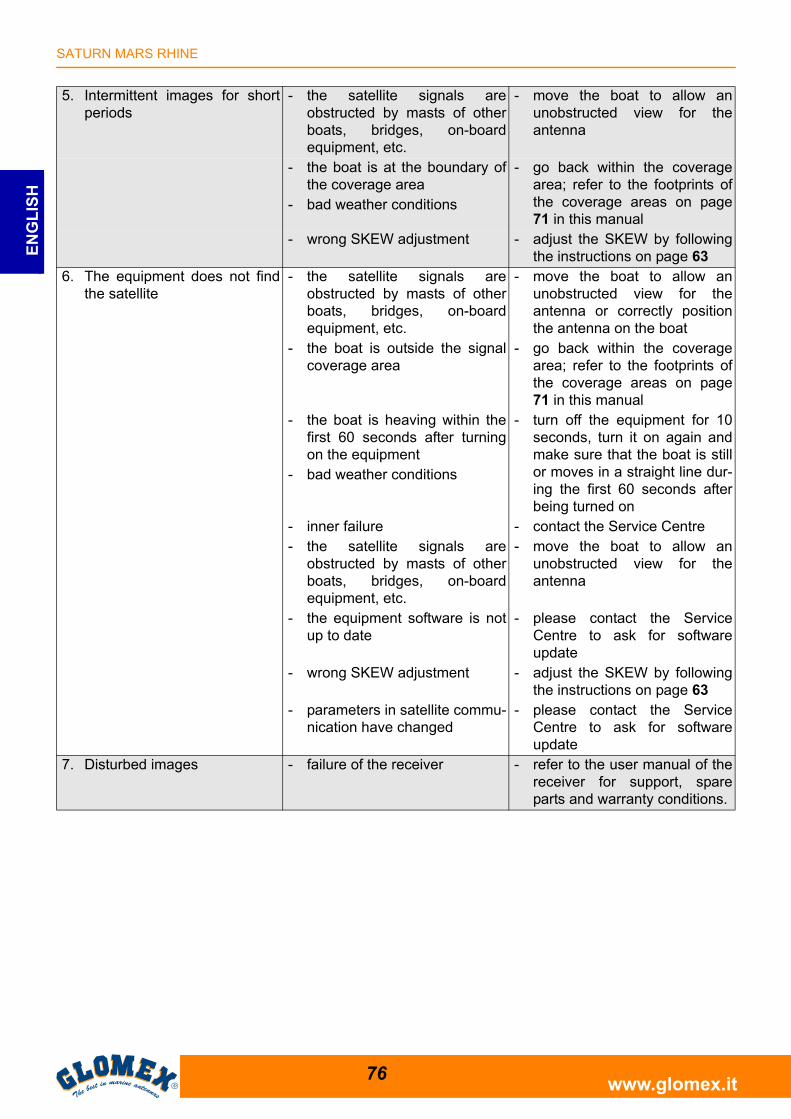
5. Intermittent images for shortperiods
- the satellite signals areobstructed by masts of otherboats, bridges, on-boardequipment, etc.
- move the boat to allow anunobstructed view for theantenna
- the boat is at the boundary ofthe coverage area
- bad weather conditions
- go back within the coveragearea; refer to the footprints ofthe coverage areas on page71 in this manual
- wrong SKEW adjustment - adjust the SKEW by followingthe instructions on page 63
6. The equipment does not findthe satellite
- the satellite signals areobstructed by masts of otherboats, bridges, on-boardequipment, etc.
- move the boat to allow anunobstructed view for theantenna or correctly positionthe antenna on the boat
- the boat is outside the signalcoverage area
- go back within the coveragearea; refer to the footprints ofthe coverage areas on page71 in this manual
- the boat is heaving within thefirst 60 seconds after turningon the equipment
- bad weather conditions
- turn off the equipment for 10seconds, turn it on again andmake sure that the boat is stillor moves in a straight line dur-ing the first 60 seconds afterbeing turned on
- inner failure - contact the Service Centre- the satellite signals are
obstructed by masts of otherboats, bridges, on-boardequipment, etc.
- move the boat to allow anunobstructed view for theantenna
- the equipment software is notup to date
- please contact the ServiceCentre to ask for softwareupdate
- wrong SKEW adjustment - adjust the SKEW by followingthe instructions on page 63
- parameters in satellite commu-nication have changed
- please contact the ServiceCentre to ask for softwareupdate
7. Disturbed images - failure of the receiver - refer to the user manual of thereceiver for support, spareparts and warranty conditions.
SATURN MARS RHINE
77www.glomex.it
EN
GL
ISH
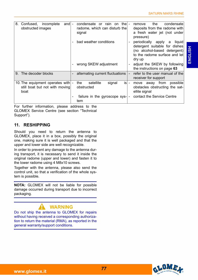
For further information, please address to theGLOMEX Service Centre (see section “TechnicalSupport”).
11. RESHIPPING
Should you need to return the antenna toGLOMEX, place it in a box, possibly the originalone, making sure it is well packaged and that theupper and lower side are well recognizable.In order to prevent any damage to the antenna dur-ing transport, it is necessary to send it inside theoriginal radome (upper and lower) and fasten it tothe lower radome using 4 M8x10 screws.Together with the antenna, please also send thecontrol unit, so that a verification of the whole sys-tem is possible.
NOTA: GLOMEX will not be liable for possibledamage occurred during transport due to incorrectpackaging.
S WARNINGDo not ship the antenna to GLOMEX for repairswithout having received a corresponding authoriza-tion to return the material (RMA), as reported in thegeneral warranty/support conditions.
8. Confused, incomplete andobstructed images
- condensate or rain on theradome, which can disturb thesignal
- remove the condensatedeposits from the radome witha fresh water jet (not underpressure)
- bad weather conditions - periodically apply a liquiddetergent suitable for dishes(no alcohol-based detergent)to the radome surface and letdry up
- wrong SKEW adjustment - adjust the SKEW by followingthe instructions on page 63
9. The decoder blocks - alternating current fluctuations - refer to the user manual of thereceiver for support
10. The equipment operates withstill boat but not with movingboat
- the satellite signal isobstructed
- move away from possibleobstacles obstructing the sat-ellite signal
- failure in the gyroscope sys-tem
- contact the Service Centre
SATURN MARS RHINE
78www.glomex.it
EN
GL
ISH
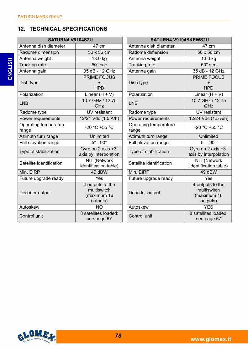
12. TECHNICAL SPECIFICATIONS
SATURN4 V9104S2UAntenna dish diameter 47 cmRadome dimension 50 x 56 cmAntenna weight 13.0 kgTracking rate 50° secAntenna gain 35 dB - 12 GHz
Dish typePRIME FOCUS
+HPD
Polarization Linear (H + V)
LNB10.7 GHz / 12.75
GHzRadome type UV resistantPower requirements 12/24 Vdc (1.5 A/h)Operating temperature range
-20 °C +55 °C
Azimuth turn range UnlimitedFull elevation range 5° - 90°
Type of stabilizationGyro on 2 axis +3°
axis by interpolation
Satellite identificationNIT (Network
identification table)Min. EIRP 49 dBWFuture upgrade ready Yes
Decoder output
4 outputs to the multiswitch
(maximum 16 outputs)
Autoskew NO
Control unit8 satellites loaded:
see page 67
SATURN4 V9104SKEWS2UAntenna dish diameter 47 cmRadome dimension 50 x 56 cmAntenna weight 13.0 kgTracking rate 50° secAntenna gain 35 dB - 12 GHz
Dish typePRIME FOCUS
+HPD
Polarization Linear (H + V)
LNB10.7 GHz / 12.75
GHzRadome type UV resistantPower requirements 12/24 Vdc (1.5 A/h)Operating temperature range
-20 °C +55 °C
Azimuth turn range UnlimitedFull elevation range 5° - 90°
Type of stabilizationGyro on 2 axis +3°
axis by interpolation
Satellite identificationNIT (Network
identification table)Min. EIRP 49 dBWFuture upgrade ready Yes
Decoder output
4 outputs to the multiswitch
(maximum 16 outputs)
Autoskew YES
Control unit8 satellites loaded:
see page 67
SATURN MARS RHINE
79www.glomex.it
EN
GL
ISH
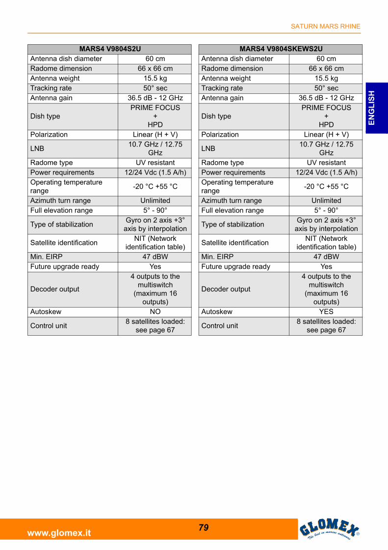
MARS4 V9804S2UAntenna dish diameter 60 cmRadome dimension 66 x 66 cmAntenna weight 15.5 kgTracking rate 50° secAntenna gain 36.5 dB - 12 GHz
Dish typePRIME FOCUS
+HPD
Polarization Linear (H + V)
LNB10.7 GHz / 12.75
GHzRadome type UV resistantPower requirements 12/24 Vdc (1.5 A/h)Operating temperature range
-20 °C +55 °C
Azimuth turn range UnlimitedFull elevation range 5° - 90°
Type of stabilizationGyro on 2 axis +3°
axis by interpolation
Satellite identificationNIT (Network
identification table)Min. EIRP 47 dBWFuture upgrade ready Yes
Decoder output
4 outputs to the multiswitch
(maximum 16 outputs)
Autoskew NO
Control unit8 satellites loaded:
see page 67
MARS4 V9804SKEWS2UAntenna dish diameter 60 cmRadome dimension 66 x 66 cmAntenna weight 15.5 kgTracking rate 50° secAntenna gain 36.5 dB - 12 GHz
Dish typePRIME FOCUS
+HPD
Polarization Linear (H + V)
LNB10.7 GHz / 12.75
GHzRadome type UV resistantPower requirements 12/24 Vdc (1.5 A/h)Operating temperature range
-20 °C +55 °C
Azimuth turn range UnlimitedFull elevation range 5° - 90°
Type of stabilizationGyro on 2 axis +3°
axis by interpolation
Satellite identificationNIT (Network
identification table)Min. EIRP 47 dBWFuture upgrade ready Yes
Decoder output
4 outputs to the multiswitch
(maximum 16 outputs)
Autoskew YES
Control unit8 satellites loaded:
see page 67
SATURN MARS RHINE
80www.glomex.it
EN
GL
ISH
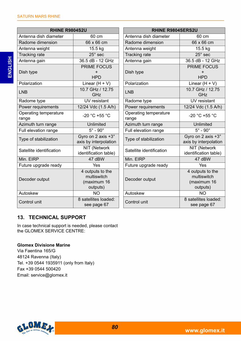
13. TECHNICAL SUPPORT
In case technical support is needed, please contactthe GLOMEX SERVICE CENTRE:
Glomex Divisione MarineVia Faentina 165/G 48124 Ravenna (Italy)Tel. +39 0544 1935911 (only from Italy)Fax +39 0544 500420Email: [email protected]
RHINE R9804S2UAntenna dish diameter 60 cmRadome dimension 66 x 66 cmAntenna weight 15.5 kgTracking rate 25° secAntenna gain 36.5 dB - 12 GHz
Dish typePRIME FOCUS
+HPD
Polarization Linear (H + V)
LNB10.7 GHz / 12.75
GHzRadome type UV resistantPower requirements 12/24 Vdc (1.5 A/h)Operating temperature range
-20 °C +55 °C
Azimuth turn range UnlimitedFull elevation range 5° - 90°
Type of stabilizationGyro on 2 axis +3°
axis by interpolation
Satellite identificationNIT (Network
identification table)Min. EIRP 47 dBWFuture upgrade ready Yes
Decoder output
4 outputs to the multiswitch
(maximum 16 outputs)
Autoskew NO
Control unit8 satellites loaded:
see page 67
RHINE R9804SERS2UAntenna dish diameter 60 cmRadome dimension 66 x 66 cmAntenna weight 15.5 kgTracking rate 25° secAntenna gain 36.5 dB - 12 GHz
Dish typePRIME FOCUS
+HPD
Polarization Linear (H + V)
LNB10.7 GHz / 12.75
GHzRadome type UV resistantPower requirements 12/24 Vdc (1.5 A/h)Operating temperature range
-20 °C +55 °C
Azimuth turn range UnlimitedFull elevation range 5° - 90°
Type of stabilizationGyro on 2 axis +3°
axis by interpolation
Satellite identificationNIT (Network
identification table)Min. EIRP 47 dBWFuture upgrade ready Yes
Decoder output
4 outputs to the multiswitch
(maximum 16 outputs)
Autoskew NO
Control unit8 satellites loaded:
see page 67