Embed Size (px)
Citation preview

Pulse XT 25e ARF
Assembly Manual

Table of Contents
Introduction............................................................................................. 2Specifications.......................................................................................... 2Using This Manual....................................................................................3Preparation............................................................................................. 3Inspection................................................................................................ 3Kit Contents............................................................................................. 3Product Registration................................................................................. 3Required Equipment................................................................................. 4Required Tools and Adhesives................................................................... 4Optional Accessories................................................................................ 4Fuselage Assembly................................................................................... 5Landing Gear Assembly........................................................................5Tail Installation.................................................................................... 7Fuselage Servo Installation.................................................................... 8Receiver Installation............................................................................ 11
Motor and Battery Installation - Power 25..................................................11Motor and Battery Installation - Power 32..................................................13Cowling, Propeller and Spinner Installation............................................... 15Wing Assembly...................................................................................... 17Wing Joining.....................................................................................17Aileron Servo Installation.....................................................................19
Canopy and Cooling Exit Scoop Installation..............................................22Optional Float Installation....................................................................... 23Flight Preparation....................................................................................27Control Direction................................................................................ 27Control Throws................................................................................... 27Center of Gravity................................................................................28
Preflight................................................................................................. 28Battery Charging................................................................................28Range Testing the Radio......................................................................28Final Checks...................................................................................... 28
Optional Items........................................................................................29Lithium Polymer Battery Pack Information...................................................31Instructions for Disposal of WEEE by Usersin the European Union....................................................................... 32
AMA National Model Aircraft Safety Code..............................................33Warranty Information............................................................................. 34
Introduction
E-flite’s Pulse™ XT 25e is a 25-size electric version of the classic Hangar 9®Pulse 40 XT. This is a great flying sport ARF that’s perfect for intermediatepilots and sport fliers who want to fly an airplane that’s more aerobatic thanhigh-wing airplanes. Based on the original Mike McConville design, the PulseXT 25e offers excellent features such as its lightweight laser-cut balsaconstruction and bolt-together wing and tail assembly.
The Pulse XT 25e is easy to maintain and quick to assemble. The wing bolts inplace, making it easy to transport. The aluminum landing gear comes alreadypainted along with factory-painted fiberglass cowling and wheel pants. Allcontrol surfaces are pre-hinged, control horns are installed, and wheels andaxles are mounted on the landing gear.
Depending on your performance desires, you can select from an E-flite Power25 or Power 32 motor. The Pulse can also be flown from the water by addingthe optional E-flite fiberglass .25 size floats (EFLA500) and utilizing theincluded aft float mount.
Specifications
Wingspan 52 in (1335mm)Length 44 in (1115mm)Wing Area 495 sq in (31.9 sq dm)Weight (with battery) 3.7 - 4.2 lb (1.7 - 1.9 kg)Radio 4-channel with 4 mini servosPower System Power 25 Brushless Outrunner with 3S LiPo
or Power 32 Brushless Outrunner with 4S LiPo
2

Using This Manual
This manual is divided into sections to make assembly of the model easier tounderstand and to provide breaks between each major section.
In addition, check boxes have been placed next to each step to keep track ofeach step completed. Steps with a single circle (Ο) are performed once, whilesteps with two circles (Ο Ο) indicate that the step will require repeating, suchas for a right or left wing panel, two servos, etc.
We recommend reading through the entire manual before beginning assemblyin order to familiarize yourself with the model and its assembly.
Preparation
Your Pulse XT 25e arrives prefinished and it is recommended that you taketime to properly prepare your work area. Clean off your work surface and laydown a foam pad or blanket to protect the finish of your model.
This is also a good time to check through the list of required parts and toolsand obtain any items not on hand that you may need to complete the model.
Inspection
Before beginning assembly of your Pulse XT 25e, inspect the kit contents andtake an inventory of the parts. If any parts are missing, defective or damaged,contact Horizon Hobby, Inc. for assistance.
Direct your email to: [email protected] or call877-504-0233 toll-free to speak to a service technician.
Kit Contents
1. Left wing panel 7. Cowling2. Right wing panel 8. Spinner3. Fuselage 9. Forward and aft (float) landing gear4. Horizontal stabilizer 10. Wheel pants5. Vertical stabilizer 11. Pushrod set6. Canopy
Not pictured:- Accessory bag (cooling scoop, control hardware, hook and loop material)- Wing parts bag (dihedral joiners, wing dowels and aileron pushrods)- Hardware bag (bolts, screws, washers, spacers)- Float mount spacers (4)
Product Registration
Register your product online at: www.e-fliterc.com/register/
3

Required EquipmentRadioYou will need a minimum of a 4-channel radio for this model. A completeradio system can be purchased or, if you have a suitable transmitter, just theairborne components will be required.
Complete SystemSpektrum DX6i 2.4GHz DSM2 radio system SPM6600(4) JR SPORT™ MN48 mini servos JSP20040(2) JR SPORT 6” servo extension leads JSP98110(2) JR SPORT 3” servo extension leads JSP98100-or (1) Y-harness (JSP98020) if not using the dual aileron function
Airborne ComponentsSpektrum AR6200 DSM2 2.4GHz receiver SPMAR6200(4) JR SPORT MN48 mini servos JSP20040(2) JR SPORT 6” servo extension leads JSP98110(2) JR SPORT 3” servo extension leads JSP98100-or (1) y-harness (JSP98020) if not using the dual aileron function
MotorThe Pulse XT 25e is designed to accept either the E-flite Power 25 or Power 32Brushless Outrunner motors and comes complete with the hardware for eitherinstallation.
Sport Motor SetupE-flite Power 25 brushless outrunner motor EFLM4025AE-flite 40-Amp Pro Brushless ESC EFLA1040E-flite 3200mAh 3S LiPo battery pack EFLB32003SAPC 12 x 8E propeller APC12080E
High Power Motor SetupE-flite Power 32 brushless outrunner motor EFLM4032AE-flite 60-Amp Pro Brushless ESC EFLA1060E-flite 3200mAh 4s LiPo battery pack EFLB32004SAPC 13 x 6.5E propeller APC13065E
Required Tools and Adhesives
E-flite parkflyer tool assortment 1/16 (1.5mm) in drill bitE-flite 1/4" nut driver 5/64 in (2mm) drill bit7/64” balldriver Dremel rotary tool12 minute epoxy High speed cutoff wheelThin CA (cyanoacrylate) High speed rotary cutterCanopy glue Low-tack tapePin drill Clear tapeTapered reamer Felt-tip pen3/32” ball driver Tongue depressors#0 Philips screwdriver Mixing sticks#1 Philips screwdriver Dental flossThreadlock
For Float installation
11/64 in (4.5mm) drill bitFlat fileDrillRuler1.5mm Allen wrench (included with EFLA500)
Optional Accessories
E-flite 25-size Float Set EFLA500E-flite 1 - 5 cell LiPo charger with balancer EFLC505Power Meter EFLA110LiPo Charge Safe Charging Bag KSJ1821JR MatchMaker™ JRPA91536” flex cable (required for float installation) SUL508
4

Landing Gear Assembly and Installation
Required parts:FuselageMain landing gear (wheels installed)Wheel pants(2) 6-32 x 1/2" socket head bolts(2) #6 steel washers(4) #2 x 3/8” sheet metal screws
Required tools and adhesives:7/64” balldriver Thin CADremel rotary tool w/ cutoff wheel #0 Philips screwdriver1/16 in (1.5mm) drill bit ThreadlockPin drill Felt-tip pen
Ο Ο 1. The axles as supplied are suitable for the optional float kit installation(EFLA500) and require trimming for use with wheel pants. Cut off the exposedportion of the axle leaving approximately 1/4” protruding from the wheelcollar. Approximately 1” total axle length is the longest that will fit within thewheel pant. A cutoff wheel in a rotary tool works well for this. Do this for bothmain axles.
Ο 2. Use a 7/64” balldriver to install the landing gear on the fuselage withtwo 6-32” x 1/2” socket head bolts and #6 steel washers. The landing gearhas a slight sweep and it should be installed on the model angled forward.Threadlock may be used to prevent the bolts from loosening in flight.
Ο Ο 3. Locate the wheel pant on the landing gear and mark the hole locationswith a felt-tip pen. The trim lines on the wheel pant and fuselage can be usedto align the parts to each other. For another method see the E-tip on page 6.
5

6
Ο Ο 4. Using a 1/16 in (1.5mm) drill bit in a pin drill, drill two holes wheremarked on the wheel pant. Apply a drop of thin CA in each hole to strengthenthe wood.
Ο Ο 5. Using a #0 Philips screwdriver, install the wheel pant on the landinggear with two #2 x 1/2” sheet metal screws.
An accurate method of aligning the wheel pants to the fuselage isto level the fuselage with a block under the rear end, then supportthe wheel pant with another block while marking the locationholes for the attachment screws with a felt-tip marker.
Dimensions of 6-7/8” (175mm) under the rearmost point of thefuselage, and 1-1/2” (38mm) to the upper aft corner of thewheel pant work well.
Ο 6. Now install the opposite wheel pant following steps 3 - 5.

Ο 2. Slide the vertical stabilizer into place. It will be necessary to deflect therudder to the right in order for the rudder horn to clear the elevator. The 4-40rods will pass through the horizontal stabilizer and the fuselage. The forwardend of the vertical stabilizer assembly will slide over the turtledeck tab, and thefin post will slide between the aft fuselage sides.
Ο 3. Install the two washers and retaining nuts with a 1/4” nut driver orwrench. Tighten them enough that the tail assembly is seated fully and is notloose.
Tail Installation
Required PartsFuselageVertical stabilizerHorizontal stabilizer(2) 4-40 x 1/4" locknuts(2) #4 steel washers
Required Tools1/4” nut driver or wrench
Ο 1. Place the horizontal stabilizer on the aft fuselage. Its leading edge needsto locate under the tab on the rear turtledeck former as shown.
7

8
Fuselage Servo Installation
Required Items(2) Servos and hardware(2) 23 5/8” rudder and elevator pushrods(2) nylon clevises and silicone keepers(2) pushrod keepersFuselageRadio system (Tx, Rx, battery)JR MatchMaker (optional)
Required Tools1/16 in (1.5mm) drill bit #1 Philips screwdriverPin drill Low-tack tape5/64 in (2mm) drill bit Tongue depressors/popsicle sticks#0 Philips screwdriver ClothespinsThin CA Felt-tip penSidecutters
Ο Ο 1. Prepare the fuselage servos by installing the rubber grommets andbrass bushings in the mounting lugs. Place the servos in the fuselage and markthe screw hole locations using a felt-tip pen.
Ο Ο 2. Using a 1/16 in (1.5mm) drill bit in a pin drill, drill the four mountingholes for the rudder and elevator servos. Apply a small drop of thin CA toeach hole after drilling to strengthen the wood.
Ο Ο 3. Using a #0 Philips screwdriver, and the screws provided with theservos, install the rudder and elevator servos in the fuselage mounting tray asshown. In this view, the front of the fuselage is to the left.

Ο Ο 4. Remove the servo arm using a #1 philips screwdriver. Using sidecutters,trim three of the arms from a standard four arm servo horn, leaving one longarm. Drill a 5/64 in (2mm) hole in the outermost hole using a pin drill. Centerthe servo using a JR MatchMaker or your radio system, and install the arm asshown using a #1 Philips screwdriver.
Ο Ο 5. Install the clevises and silicone keepers on the pushrods as shown, theninstall the pushrods in the fuselage from their openings in the rear fuselagesides.
JR’s MatchMaker is a great tool for setting up a model because itallows you to center and cycle servos without the need for atransmitter and receiver.
It will accurately center two servos simultaneously, and also cyclethem at various speeds, allowing you to evaluate end points andcontrol surface travels right on the workbench.
9

10
Ο Ο 6. Attach the clevises to the control horn on the elevator at the third holefrom the mounting surface, and on the rudder at the second hole from themounting surface. Do not install the silicone keepers at this time. We will dothat later in construction on Page 27.
Ο Ο 7. With the control surfaces and servos in their neutral positions, mark thelocation of the pushrod at the servo arm hole using a felt-tip pen. Place a 90-degree bend (towards the bottom of the fuselage) in each of the pushrods inthis location. Install the nylon keepers on the pushrods at the servo arms. Trimthe remaining wire using sidecutters.
Here are a couple of methods that work well to center thecontrol surfaces for setup.
One technique is to use a pair of tongue depressors andclothespins. Another is to use low-tack tape. Fold a tab in theend of the tape for easy removal
Ο 8. Repeat steps 1 - 7 to install the second servo and pushrod. Note that step6 dictates which hole to hook the clevis to for both the rudder and elevator.

Receiver Installation
Required PartsFuselageSpektrum AR6200 ReceiverAdhesive backed hook and loop tape
Ο 1. Install the main and satellite receiver in the fuselage as shownwith adhesivebacked hook and loop tape. An alternate location for the satellite receiver isalso shown. The rudder and elevator servos can be plugged in at this time.
Motor and Battery InstallationE-flite Power 25
Required PartsE-flite Power 25 Motor with hardwareE-flite 40A ESCE-flite BatteryPropeller(4) 4-40 x 1/2" socket head boltsAdhesive backed hook and loop tape(2) Hook and loop straps
Required Tools3/32” balldriver#1 Philips screwdriverThreadlock
NNoottee:: Your E-flite Pulse XT 25e has been designed to accept the Power 25 andPower 32 motors. We have flown the model on wheels and floats with bothmotors. The Power 25 delivers adequate power to fly the model on floats butfor extreme power you may opt for the Power 32 and 4S battery combination.
Ο 1. Using a #1 Philips screwdriver, install the mount on the rear of the motorusing the countersunk Philips head screws included with the motor. You mayuse threadlock to prevent these screws vibrating loose during flight.
11

12
Ο 2. Using a 3/32” balldriver, install the motor on the firewall with four 4-40x 1/2" socket head bolts. The motor wires should exit towards the bottom ofthe fuselage. You may use threadlock to prevent these screws from vibratingloose in flight.
Ο 3. Remove the battery hatch by sliding it forward to disengage the magnets,and lifting at the rear. It can then be pulled rearwards and off the model.
Ο 4. Install the battery with two hook and loop straps. Slots are provided onthe floor of the battery compartment for the straps to pass through. The naturalcurl of the straps will allow them to be fed down one slot, under the batterycompartment floor, then up through the opposite slot.
Ο 5. Install the ESC on the right-hand side of the battery compartment withhook and loop tape. The battery leads, switch leads and throttle leads will betowards the rear of the model. Connect the ESC to the motor.

Motor and Battery Installation E-flite Power 32
Required PartsE-flite Power 32 Motor with hardwareE-flite 60A ESCE-flite BatteryPropeller(4) 4-40 x 3/4" socket head boltsAdhesive backed hook and loop tape(2) Hook and loop straps(4) 4mm aluminum motor mount spacers
Required Tools3/32” balldriver#1 Philips screwdriverThreadlock
Ο 1. Using a #1 Philips screwdriver, install the mount on the rear of the motorusing the countersunk Philips head screws included with the motor. You mayuse threadlock to prevent these screws vibrating loose during flight.
Ο 2.. Using a 3/32” balldriver, install the motor on the firewall with four 4-40x 3/4" socket head bolts and four 4mm aluminum spacers. The motor wiresshould exit towards the bottom of the fuselage. You may use threadlock toprevent these screws from vibrating loose in flight.
Ο 3. Remove the battery hatch by sliding it forward to disengage the magnets,and lifting at the rear. It can then be pulled rearwards and off the model.
13

14
Ο 5. Install the ESC on the right-hand side of the battery compartment withhook and loop tape. The battery leads, switch leads and throttle leads will betowards the rear of the model. Connect the ESC to the motor.
Ο 4. Install the battery with two hook and loop straps. Slots are provided onthe floor of the battery compartment for the straps to pass through. The naturalcurl of the straps will allow them to be fed down one slot, under the batterycompartment floor, then up through the opposite slot.
Should you find that the rotation direction of your E-flite PowerBrushless Outrunner is opposite to that needed, reversing it is justa matter of switching any two of the motor wires.
E-flite’s Power series brushless motors and Pro series controllersare outfitted with red, blue and black power wires. Matching thecolor is not critical to their operation, it only affects the directionof rotation.

Cowling, Propeller and Spinner Installation
Required PartsFuselageCowling(4) 4-40 x 1/4" socket head bolts(4) #4 steel washersSpinner with screwsPropellerPropeller adapter (supplied with motor)
Required Tools3/32” balldriver#1 Philips screwdriverTapered reamerDremel rotary tool with high speed cutter
Ο 1. Using a 3/32” balldriver, install the cowling with four 4-40 x 1/4"socket head bolts and four #4 steel washers.
Ο 2. The spinner backplate requires the hole to be enlarged to suit thepropeller adapter. For a snug fit on the prop adapter the hole should beapproximately 9.5mm diameter. This is best done with a tapered reamer.Proceed carefully and check the fit on the shaft as you enlarge the hole.
Ο 3. Install the propeller adapter, spinner backplate and propeller. Tighten thepropeller nut with a suitably sized screwdriver or Allen wrench shaft.
15

16
Ο 4. Install the spinner cone using a #1 Philips screwdriver and the suppliedPhilips head screws.
An alternate method to drilling completely through thespinner backplate is to grind only the relief necessary toclear the propeller adapter hub.This can be done by handusing a straight cutter in a Dremel rotary tool. Theremainder of the hole can be left at its orginal size and willbe a good fit on the propeller shaft.

Wing Joining
Required PartsWing halves (L and R)(2) dihedral joiners(2) leading edge dowels(2) 6-32 x 1” socket head bolts(2) #6 steel washers
Required Tools and AdhesivesLow-tack tape12-minute epoxyClear tape 7/64” balldriverMixing cupsMixing sticksRubbing alcoholPaper towels
Ο Ο 1. Install the leading edge dowels in the wing panels with 12-minuteepoxy. Use paper towels and rubbing alcohol to clean any epoxy thatsqueezes out onto the wing.
Ο Ο 2.. Upon installation, approximately 5/16” to 3/8” of the dowel shouldprotrude from the leading edge of the wing.
Ο Ο 3. The rear side of the dowel is accessible through the wing root rib and asmall amount of epoxy can be added here to secure its installation.
17

18
Ο 4. Apply low-tack tape to the upper and lower surfaces of the center of thewing panels as shown. This will allow for easy clean up of any excess glue andmake for a clean joint.
Ο 5. Apply a piece of clear tape to the front and rear wing saddle area wherethe wing leading and trailing edges will come in contact with the fuselage.
Ο 6. 12-minute epoxy is used to install the dihedral joiners and join the wing.Glue the two dihedral joiners to each other.
Ο 7. Using a mixing stick, apply epoxy to the dihedral joiner slot in each wingpanel, and to the exposed root rib of one wing panel.

Ο 8. Install the dihedral joiners in one wing slot and slide the other wing panelonto the joiner. Wipe off any excess epoxy that squeezes out of the joint withrubbing alcohol and a paper towel.
Using a 7/64” balldriver, install the wing on the fuselage with two 6-32” x 1”socket head bolts. Tighten the bolts just enough that the wing sits snugly in thewing saddle, and that the two wing panels are exactly aligned with each otheralong their bottom surface. Wipe off any excess glue from the wing joint witha paper towel.
9. Allow the glue to dry then remove the wing from the fuselage. Remove thetape from the wing and fuselage.
Aileron Servo Installation.
Required Parts(2) servos and hardware(2) 6” servo extension leads(2) 4-3/4" aileron pushrods(2) nylon clevises and silicone keepers(2) pushrod keepersRadio system (Tx, Rx, battery)JR MatchMaker (optional)
Required Tools and Adhesives1/16 in (1.5mm) drill bit SidecuttersPin drill Felt-tip pen5/64 in (2mm) drill bit Thin CA#0 Philips screwdriverTape/heat-shrink tubing/dental floss
Ο 1. Install the rubber grommets and brass bushings in each aileron servo.Attach a 6” servo extension lead to each servo and secure it with tape, heatshrink tubing or dental floss.
19

20
Ο 2. A string is provided in each wing half to draw the aileron lead throughthe wing. Attach the end of the string to the aileron servo lead and pull itcarefully through the wing to the center. Once both leads have been pulledthrough, they can be secured to each other with tape to prevent them fallingback into the wing.
Ο Ο 3. Place the servos in the wing openings and mark the screw holelocations with a felt-tip pen.
Ο Ο 4. Using a 1/16 in (1.5mm) drill bit in a pin drill, drill the four mountingholes for each aileron servo. After drilling, apply a small drop of thin CA toeach hole to strengthen the wood.
Ο Ο 5. Using a #0 Philips screwdriver, and the screws provided with theservos, install the aileron servos with the output shaft towards the trailing edgeof the wing.

Ο Ο 7. Prepare each of the 4-3/4” long aileron pushrods with a clevis andsilicone keeper.
Ο Ο 8. Center the aileron servo using your radio or JR MatchMaker. Attachthe clevis to the aileron horn at the third hole from the surface and mark thelength at the servo arm. Bend the pushrod up (away from the wing surface) atthis location and install it on the servo arm with a pushrod keeper.
Ο Ο 6. Using a #1 Philips screwdriver remove the servo horn. Using sidecuttersremove three of the four arms, leaving one long arm. Using a pin drill, enlargethe outermost hole to 5/64 in (2mm) to accept the pushrod. Center the servoand install the arm towards the wing tip as shown.
9. Follow steps 3 through 8 to install the opposite aileron servo.
21

22
Canopy and Cooling Exit Scoop
Required PartsFuselageCanopyCooling Exit Scoop
Required Tools and AdhesivesLow-tack tapeCanopy Glue
Ο 1. Trial fit the canopy on the fuselage. Once satisfied with its location, applyglue to the inside of the canopy at the areas of the painted frame, and installon the fuselage. Tape can be used to hold it in place while the glue dries.Allow the glue to dry completely before removing the tape.
Ο 2. Follow the same procedure to attach the cooling exit scoop on the lowerfuselage behind the wing in the location shown. Note that the opening facestowards the rear of the model.
NNoottee:: If you opt to fly from land please proceed to the Flight Preparationsection on page 27. If you are installing floats, please proceed to the nextpage.

Optional Float Installation.
Required parts:E-flite fiberglass 25-size Float SetSullivan 36” flex cablePulse XT 25e (assembled)(4) 1/8” float mount spacers (included in Pulse kit)
Required tools and adhesives:#1 Philips screwdriver Sidecutters7/64 in balldriver 5/64 in (2mm) drill bit1.5mm Allen wrench 11/64 in (4.5mm) drill bit1/16 in (1.5mm) drill bit Thin CAPin drill Flat fileFelt-tip pen DrillThreadlock Ruler
Ο 1. Locate the parts from the float set as shown below, plus the four floatmount spacers from your Pulse kit. Not required for float installation on thePulse are the wire float mount, the sub-fin and the water rudder pushrod.
Refer to the Float Set assembly manual in addition to these instructions forreference when assembling the floats.
Ο Ο 2. Using a #1 Philips screwdriver, attach two of the mounting brackets andspacers to each of the floats with 3mm x 12mm sheet metal screws. For the twofloats a total of four brackets, four spacers and sixteen screws are required.
Ο Ο 3. Remove the wheel pants and wheels from the main landing gear onyour Pulse. The 1.5mm Allen wrench in the Float Set hardware bag will fit thePulse wheel collars. Install the aft float mount landing gear using the wingattach bolts. When correctly installed the gear will angle forward and the holefor the water rudder cable will be on the left.
23
24
Ο Ο 4. Use a file or rotary tool to make a 1/4” wide flat on the top of each ofthe four axles. The flat should be located approximately 9/16” (14mm)outboard of the hexagonal axle base.
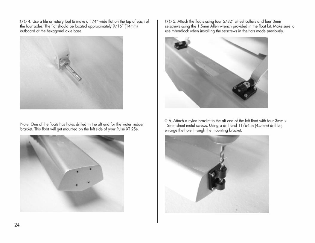
Ο Ο 5. Attach the floats using four 5/32” wheel collars and four 3mmsetscrews using the 1.5mm Allen wrench provided in the float kit. Make sure touse threadlock when installing the setscrews in the flats made previously.
Note: One of the floats has holes drilled in the aft end for the water rudderbracket. This float will get mounted on the left side of your Pulse XT 25e.
Ο 6. Attach a nylon bracket to the aft end of the left float with four 3mm x12mm sheet metal screws. Using a drill and 11/64 in (4.5mm) drill bit,enlarge the hole through the mounting bracket.

Ο 7. Install the rudder assembly, steering arm and pushrod connector on thenylon bracket. Refer to pages 12 and 13 in the Float Set assembly manual forguidance. The pushrod connector will go in the hole closest to the rudder post.
Ο 8. Install a pushrod connector on the outermost hole in the rudder horn asshown. Refer to page 13 of the Float Set assembly manual for guidance.
Ο 9. The Sullivan flex cable and tube need to be cut to length prior toinstallation. The cable length will be approximately 31.5 in and the tube lengthapproximately 26.5 in.With the pushrod cable inside the pushrod tube, attach the tube to the floatwith a full brass strap and two 2mm x 10mm sheet metal screws.The end ofthe pushrod tube will be approximately 1.5” behind the brass strap. The cablecan now be installed in the pushrod connector with a 3mm setscrew as shown.
Ο 10. Install the other end of the cable in the pushrod connector on the rudderhorn as shown and secure with a 3mm setscrew using a 1.5mm Allen wrench.
25

26
Ο 11. Use the two remaining full brass straps to attach the pushrod tube to theleft side of the Pulse fuselage. Locate the straps as shown in the picture belowusing the following dimensions as a guide. There are fuselage frames at theselocations; ensure that the screws are located in the center of the frame and willnot interfere with any internal items such as pushrods.
Aft strap: approximately 3/8” forward of stabilizer leading edge, andcentered 9/16” up from bottom of fuselage.
Forward strap: approximately 6-1/2” forward of stabilizer leading edge, and5/8” up from bottom of fuselage.
Use a 1/16” drill bit and pin drill to make the holes for the 2mm x 10mmscrews. Strengthen each hole with a small drop of thin CA and allow to cure.Using a #0 Philips screwdriver, attach the straps over the pushrod tube withboth the air and water rudders centered.
13. Refer to page 16 in the Float Set assembly manual to finalize theinstallation of the floats. This will involve final adjustment of linkages to ensurethat the rudder is aligned and operates correctly.
It is extremely important that you verify the center of gravity is still correct withthe floats installed. It will be more accurate to check the CG of your floatequipped Pulse with the model right side up, as opposed to inverted when thewheels are installed.
Pages 26 and 27 of your Float Set assembly manual include some tips forflying from floats. If you are a first-time water flier, please take the time to readthese pages before heading out to the lake.
Ο 12. Attach the water rudder cable housing to the left float mount strut usingthe cable tie provided in the Float Set hardware bag. Trim the excess tiematerial using cutters or a blade.

Flight Preparation
Control Directions1. Connect the throttle lead from the ESC to the receiver.
2. Connect the wing servos to the receiver with two 3” extension leads(JSP98100) if using the dual aileron function in your transmitter, otherwise usea Y-harness (JSP98020). Attach the wing to the model.
3. Connect battery power to the ESC and using your radio verify the correctrotation of the motor. Viewed in the direction of flight, the propeller shouldrotate clockwise. We have printed an E-tip regarding the switching direction ofyour motor on page 15 for reference.
4. Center the trims on your transmitter and check that the control surfaces areneutral. Large adjustments should be made at the control surface by adjustingthe clevis, fine-tuning can be done using the transmitter subtrim function.
5. Verify that the control surfaces operate in the correct direction using thefollowing diagram. Use the servo reversing function in your transmitter asnecessary to correct the direction of motion.
Control ThrowsUse a ruler to set the control throws for the ailerons, rudder and elevator. Theposition of the pushrod can be altered at either the servo or control surface toadjust the amount of control throw. Moving the pushrod closer to the center ofthe servo, or further from the control surface, will have the effect of reducingsurface travel, and vice versa.
These measurements are taken at the widest part of the control surface. Theyare a general guide from our own flight testing and you can experiment withmore or less throw to suit your preferred flying style.
Low RateAileron 3/8” (10mm) up and downElevator 7/8” (22mm) up and downRudder 2” (50mm) left and right
High RateAileron 5/8” (16mm) up and downElevator 1-1/8” (29mm) up and downRudder 2-1/2” (64mm) left and right
Once you have set the control throws, install the silicone keepers on all theclevises. This will prevent any possible failure in flight of a clevis poppingloose.
27

28
Center of Gravity (CG)The recommended center of gravity range for the Pulse XT 25e is 2.5 - 3.0”(63 - 76mm) behind the leading edge of the wing. Before making thismeasurement ensure that the model is in a ready-to-fly state, with allcomponents in place including batteries, hatches and radio equipment.
Place a piece of tape on the upper surface of each wing beside the fuselageand mark the center of gravity location with a felt-tip marker. Suspend themodel iinnvveerrtteedd at the measured points on a commercial CG measuring device,or it can be lifted with a finger at each of those points.
NNoottee:: If flying with floats please check the CG with model right side up.
The model should hang level when suspended at the desired point. The batterypack can be moved forward or aft to correct any tendency for the model tobalance nose or tail heavy. Stick-on lead weights can also be used for thispurpose.
After the model is flown you may wish to adjust the center of gravity slightly tosuit your flying style. Use caution if moving the CG further aft as it willdecrease the stability of the model, and increase control sensitivity, particularlythe elevator. Moving the CG forward will have the opposite effect.
Preflight
Battery ChargingUse the recommended charger for the batteries being used in your radio andmodel, and follow the charging instructions.
If using Lithium Polymer (LiPo) batteries be aware that they are significantlymore volatile than alkaline, Nickel Cadmium or Nickel Metal Hydride batteriesused in other RC applications. Follow the battery manufacturer’s instructionsand warnings closely. Mishandling or incorrect handling of LiPo batteries canresult in fire. Do not charge LiPo batteries unattended.
Refer to page 31 for more detailed information on handling LiPo batteries.
Range Testing your RadioBe sure to range test your radio before each flying session, or when you havemade any repairs or changes to the model. Follow the instructions providedwith your radio to perform the range check, which usually involves limiting theoutput power of the transmitter while checking model function at a prescribeddistance.
Final ChecksBefore flying, make a last check of the model and it’s functions, especially ifyou have made any setup or programming changes.
- confirm that all control surfaces move in the correct direction- check the radio installation for security - check motor installation and correct direction of rotation- check the integrity of control surfaces and hinges- check pushrods and control horns for security of attachment

Optional Items
25-Size Float Set
E-flite quick-mount floats are designed specifically for 25-size airplanes thatare float-ready out of the box, so you can go from pavement to pond in justminutes. These floats are constructed of durable fiberglass, and are pre-painted. A pre-assembled water rudder and all mounting hardware isincluded (EFLA500).
E-flite 1-5 Cell LiPo Charger with Balancer
An Intelligent Balance Charger for 1-5 cell LiPo or Li-Ion batteries. Features alarge 2-line backlit LCD display, polarity protection and a safety timer. Chargerate is adjustable from 100mAh to 5000mAh. To protect your valuable LiPopacks the charger also has alarm warning and auto shut-off for conditionssuch as charge time over limit, charge capacity over limit, reverse voltageconnection, input voltage error, connection breakdown, short circuit, andvoltage differences during charge (EFLC505).
29

30
E-flite Power Meter
The E-flite Power Meter is designed for inline monitoring of Volts, Amps, Watts,and Capacity, based on the mode you select to display on the digital LCDscreen. For pilots who fly any electric airplanes and desire to accurately set uptheir airplanes for maximum performance, the Power Meter does not includeconnectors so you can customize it to fit your needs (EFLA110).
DX6i 6-Channel Radio by Spektrum
The 6-channel DX6i uses the same DSM2™ technology found in theSpektrum™ DX7 and includes an impressive list of programming features forboth airplanes and helicopters that are both simple to access and use. It comeswith the new AR6200 DSM2 6-channel receiver that is robust enough to use inlarge models yet compact enough to fit in many parkflyers. The DX6i is alsocompatible with all existing Spektrum aircraft receivers. Whatever kind offlying you do, the DX6i can be adapted to most any model in your existingcollection that requires 6 channels or less (SPM6600).

Lithium Polymer Battery Pack Information
Lithium Polymer (LiPo) batteries are significantly more volatile than otherrechargeable batteries used in RC applications. Failure to read and followthese instructions and safety precautions may result in fire, personal injury anddamage to property. E-flite, Horizon Hobby, Inc., its retailers, and any other representatives, assumeabsolutely no liability for use of these products or failure to comply with theassociated instructions and precautions.
Never ship batteries without the express permission of the recipient.Batteries containing 25% or more charge cannot be shipped safely.Batteries which are damaged cannot be shipped safely. Damage or lossdue to unsafe shipping is the legal responsibility of the person who shippedthe product.
CAUTION: LiPo batteries may ignite under certain conditions. Please readall safety precautions before use.
Please call 877-504-0233 with any concerns or questions regarding E-fliteLiPo battery products or warranty.
United Kingdom:Please call +44 1279 641 097 [email protected] with any questions or concerns regarding thisproduct or warranty.
Germany:Please call +49 4121 46199 66 [email protected] with any questions or concerns regarding thisproduct or warranty.
Usage Guidelines, Warnings and Safety Precautions.
•LiPo batteries may explode if damaged or disposed of improperly.•Always inspect batteries before charging.•Never charge or use a LiPo battery that shows any damage or disfigurementof any kind. Swelling is a sign of internal damage. Any breach of protectivecover, wiring or plugs is also a reason to discontinue use (see DisposalInstructions).•Use a specific Lithium Polymer charger only. Do not use a NiCd or NiMHcharger- failure to do so may cause a fire, which may result in personal injuryand/or property damage.•Never charge around or in the area of any flammable or combustiblematerials.•Always charge LiPo batteries in or on fire resistant materials or containers.•Never leave battery and charger unattended while in use. Improper chargingor discharging of LiPo batteries could result in fire.•Constantly monitor the temperature of the battery pack while charging. If thebattery becomes hot to the touch discontinue charging immediately.Disconnect the battery from the charger and observe it in a safe place for atleast 1 minute.•If at any time you see a battery starting to balloon or swell, discontinuecharging or using immediately.•Lithium batteries can still ignite after at least 45 minutes due to a delayedchemical reaction. If the battery is damaged or overheats, observe the batteryin a safe area outside of any building or vehicle and away from combustiblematerial.•Do not allow children to charge LiPo battery packs.•Do not allow children to use LiPo batteries without direct adult supervision.•Shorting the wire leads can cause fire. If you accidentally short the wires, thebattery must be placed in a safe area for observation for at least 15 minutes.•Never store or charge a battery pack where the temperature will go below32 degrees Fahrenheit or above 130 degrees Fahrenheit. Extremetemperatures will damage the battery pack and may cause fire. Batteryperformance may be diminished by less extreme temperatures.•Any of the following may cause the battery to be damaged resulting inbattery swelling, leaking or fire:- Bending, folding or dropping of the battery- Damaging the edge seal of the battery- Taking the battery apart- Mixing cells of different chemistry, or types, or sizes- Mixing cells of different ages
31

32
Crash DamageIf there are signs of smoke or overheating, DO NOT go near the battery orequipment until it has been observed from a safe distance for at least 15minutes. Once it is safe, remove the battery and check for damage. Dispose ofdamaged batteries appropriately.
Swollen BatteriesImmediately stop using or charging a battery showing any signs of swelling orbecoming too warm. If the battery is not warm to the touch, move it to an opensafe area and observe it for at least 15 minutes. Be VERY CAREFUL whenmoving the batteries. Do NOT put ANY pressure on the batteries or coveringas this may cause fire.
Additional Information and Guidelines1. Battery temperature is the best indicator for safety. The E-flite LiPo battery’stemperature should never drop below 32 degrees Fahrenheit or go above 130degrees Fahrenheit while charging or discharging.2. Changing plugs or connectors is not recommended as the process isdangerous and any error can cause fire due to shorts, reverse polarity or otherimproper handling which can cause battery damage.3. Batteries should be stored in a vented, fire resistant container. Each packshould be stored in its own locked plastic bag within the container. Thenumber of packs per container should be extremely limited to avoid chainreactions. Storage temperatures should not fall below 32 degrees Fahrenheit orabove 130 degrees Fahrenheit. Damaged batteries must be kept at even moreambient temperatures. High temperatures may cause fire even withundamaged batteries.
Battery DisposalLiPo batteries require special handling for safe disposal. The following arebasic instructions for safe disposal. For more detailed safety, disposal andrecycling please go to: www.rbrc.org or www.earth911.org.
Basic Disposal InstructionsBefore discarding any LiPo battery it must be rendered safe. The followingsteps must be taken to avoid damage or injury to yourself, your property andanyone who comes in contact with the battery.
If the battery is undamaged but no longer useful:
1. Discharge the battery to a maximum of 2.5V using a slow, safe dischargemethod.2. Leave battery discharged and retest after 24 hours. Many batteriesexperience ‘rebound’ and may measure more than 2.5V after 24 hours. If thevoltage is greater than 2.5, repeat the procedure until the battery measures2.5V or less.3. Insulate each wire lead with electrical tape or other suitable material.4. Assure that wire leads cannot touch each other by taping them to oppositesides of the battery.5. Place battery in a sealed plastic bag and place bag in a sealed, vented,fire-safe container.6. Use fire-safe container to deliver battery to a recycling center authorized forLithium Polymer batteries. Please note that not all battery recycling servicesinclude LiPo’s. If no LiPo recycling facility is available in your area, contact yourlocal or state Hazmat agencies for instructions.7. If the battery or wiring is damaged, please contact your local or stateHazmat facilities for instructions. Batteries must be rendered safe before beingtransported or recycled. Do NOT transport or ship batteries which have morethan a 2.5V charge OR that show signs of damage without following theinstructions given by authorities. Damaged batteries should be rendered assafe as possible and stored in a vented fireproof container until recycled.
Instructions for Disposal of WEEE by Users in the European Union
This product must not be disposed of with other waste. Instead, it is the usersresponsibility to dispose of their waste equipment by handing it over to adesignated collection point for the recycling of waste electrical and electronicequipment. The separate collection and recycling of your waste equipment atthe time of disposal will help to conserve natural resources and ensure that it isrecycled in a manner that protects human health and the environment. Formore information about where you can drop off your waste equipment forrecyclying, please contact your local city office, your household waste disposalservice or where you purchased the product.

AMA National Model Aircraft Safety Code
GENERAL 1. A model aircraft shall be defined as a non-human-carrying device capableof sustained flight in the atmosphere. It shall not exceed limitations establishedin this code and is intended to be used exclusively for recreational orcompetition activity.2. The maximum takeoff weight of a model aircraft, including fuel, is 55pounds, except for those flown under the AMA Experimental Aircraft Rules.3. I will abide by this Safety Code and all rules established for the flying site Iuse. I will not willfully fly my model aircraft in a reckless and/or dangerousmanner.4. I will not fly my model aircraft in sanctioned events, air shows, or modeldemonstrations until it has been proven airworthy.5. I will not fly my model aircraft higher than approximately 400 feet aboveground level, when within three (3) miles of an airport without notifyingthe airport operator. I will yield the right-of-way and avoid flying in theproximity of full-scale aircraft, utilizing a spotter when appropriate.6. I will not fly my model aircraft unless it is identified with my name andaddress, or AMA number, inside or affixed to the outside of the model aircraft.This does not apply to model aircraft flown indoors.7. I will not operate model aircraft with metal-blade propellers or with gaseousboosts (other than air), nor will I operate model aircraft with fuels containingtetranitromethane or hydrazine.8. I will not operate model aircraft carrying pyrotechnic devices which explodeburn, or propel a projectile of any kind. Exceptions include Free Flight fuses ordevices that burn producing smoke and are securely attached to the modelaircraft during flight. Rocket motors up to a G-series size may be used,provided they remain firmly attached to the model aircraft during flight. Modelrockets may be flown in accordance with the National Model Rocketry SafetyCode; however, they may not be launched from model aircraft. Officiallydesignated AMAAir Show Teams (AST) are authorized to use devices andpractices as defined within the Air Show Advisory Committee Document.9. I will not operate my model aircraft while under the influence of alcohol orwithin eight (8) hours of having consumed alcohol.10. I will not operate my model aircraft while using any drug which couldadversely affect my ability to safely control my model aircraft.11. Children under six (6) years old are only allowed on a flightline or in aflight area as a pilot or while under flight instruction.12. When and where required by rule, helmets must be properly worn andfastened. They must be OSHA, DOT, ANSI, SNELL or NOCSAEapproved or comply with comparable standards.
RADIO CONTROL1. All model flying shall be conducted in a manner to avoid over flight ofunprotected people.2. I will have completed a successful radio equipment ground-range checkbefore the first flight of a new or repaired model aircraft.3. I will not fly my model aircraft in the presence of spectators until I become aproficient flier, unless I am assisted by an experienced pilot.4. At all flying sites a line must be established, in front of which all flying takesplace. Only personnel associated with flying the model aircraft are allowed ator in front of the line. In the case of airshows demonstrations straight line mustbe established. An area away from the line must be maintained for spectators.Intentional flying behind the line is prohibited.5. I will operate my model aircraft using only radio-control frequenciescurrently allowed by the Federal Communications Commission (FCC). Onlyindividuals properly licensed by the FCC are authorized to operate equipmenton Amateur Band frequencies.6. I will not knowingly operate my model aircraft within three (3) miles of anypreexisting flying site without a frequency-management agreement. Afrequency-management agreement may be an allocation of frequencies foreach site, a day-use agreement between sites, or testing which determines thatno interference exists. A frequency-management agreement may exist betweentwo or more AMA chartered clubs, AMA clubs and individual AMA members,or individual AMA members. Frequency-management agreements, includingan interference test report if the agreement indicates no interference exists, willbe signed by all parties and copies provided to AMA Headquarters.7. With the exception of events flown under official AMA rules, no poweredmodel may be flown outdoors closer than 25 feet to any individual, except forthe pilot and located at the flightline.8. Under no circumstances may a pilot or other person touch a model aircraftin flight while it is still under power, except to divert it from striking anindividual.9. Radio-controlled night flying is limited to low-performance model aircraft(less than 100 mph). The model aircraft must be equipped with a lightingsystem which clearly defines the aircraft's attitude and direction at all times.10. The operator of a radio-controlled model aircraft shall control it during theentire flight, maintaining visual contact without enhancement other than bycorrective lenses that are prescribed for the pilot. No model aircraft shall beequipped with devices which allow it to be flown to a selectedlocation which is beyond the visual range of the pilot.
33

Warranty Period:Exclusive Warranty- Horizon Hobby, Inc., (Horizon) warranties that theProducts purchased (the "Product") will be free from defects in materials andworkmanship at the date of purchase by the Purchaser.
Limited Warranty(a) This warranty is limited to the original Purchaser ("Purchaser") and is nottransferable. REPAIR OR REPLACEMENT AS PROVIDED UNDER THISWARRANTY IS THE EXCLUSIVE REMEDY OF THE PURCHASER. This warrantycovers only those Products purchased from an authorized Horizon dealer. Thirdparty transactions are not covered by this warranty. Proof of purchase isrequired for warranty claims. Further, Horizon reserves the right to change ormodify this warranty without notice and disclaims all other warranties, expressor implied.
(b) Limitations- HORIZON MAKES NO WARRANTY OR REPRESENTATION,EXPRESS OR IMPLIED, ABOUT NON-INFRINGEMENT, MERCHANTABILITYOR FITNESS FOR A PARTICULAR PURPOSE OF THE PRODUCT. THEPURCHASER ACKNOWLEDGES THAT THEY ALONE HAVE DETERMINEDTHAT THE PRODUCT WILL SUITABLY MEET THEREQUIREMENTS OF THE PURCHASER’S INTENDED USE.
(c) Purchaser Remedy- Horizon's sole obligation hereunder shall be thatHorizon will, at its option, (i) repair or (ii) replace, any Product determined byHorizon to be defective. In the event of a defect, these are the Purchaser'sexclusive remedies. Horizon reserves the right to inspect any and all equipmentinvolved in a warranty claim. Repair or replacement decisions are at the solediscretion of Horizon. This warranty does not cover cosmetic damage ordamage due to acts of God, accident, misuse, abuse, negligence, commercialuse, or modification of or to any part of the Product. This warranty does notcover damage due to improper installation, operation, maintenance, orattempted repair by anyone other than Horizon. Return of any goods byPurchaser must be approved in writing by Horizon before shipment.
Damage Limits:HORIZON SHALL NOT BE LIABLE FOR SPECIAL, INDIRECT ORCONSEQUENTIAL DAMAGES, LOSS OF PROFITS OR PRODUCTION ORCOMMERCIAL LOSS IN ANY WAY CONNECTED WITH THE PRODUCT,WHETHER SUCH CLAIM IS BASED IN CONTRACT, WARRANTY,NEGLIGENCE, OR STRICT LIABILITY. Further, in no event shall the liability ofHorizon exceed the individual price of the Product on which liability isasserted. As Horizon has no control over use, setup, final assembly,modification or misuse, no liability shall be assumed nor accepted for anyresulting damage or injury. By the act of use, setup or assembly, the useraccepts all resulting liability.
If you as the Purchaser or user are not prepared to accept the liabilityassociated with the use of this Product, you are advised to return this Productimmediately in new and unused condition to the place of purchase.
Law: These Terms are governed by Illinois law (without regard to conflict oflaw principals).
Safety Precautions:This is a sophisticated hobby Product and not a toy. It must be operated withcaution and common sense and requires some basic mechanical ability.Failure to operate this Product in a safe and responsible manner could result ininjury or damage to the Product or other property. This Product is not intendedfor use by children without direct adult supervision. The Product manualcontains instructions for safety, operation and maintenance. It is essential toread and follow all the instructions and warnings in the manual, prior toassembly, setup or use, in order to operate correctly and avoid damage orinjury.
Questions, Assistance, and Repairs:Your local hobby store and/or place of purchase cannot provide warrantysupport or repair. Once assembly, setup or use of the Product has beenstarted, you must contact Horizon directly. This will enable Horizon to betteranswer your questions and service you in the event that you may need anyassistance. For questions or assistance, please direct your email [email protected], or call 877.504.0233 toll free to speak toa service technician.
34

Inspection or RepairsIf this Product needs to be inspected or repaired, please call for a ReturnMerchandise Authorization (RMA). Pack the Product securely using a shippingcarton. Please note that original boxes may be included, but are not designedto withstand the rigors of shipping without additional protection. Ship via acarrier that provides tracking and insurance for lost or damaged parcels, asHorizon is not responsible for merchandise until it arrives and is accepted atour facility. A Service Repair Request is available at www.horizonhobby.comon the “Support” tab. If you do not have internet access, please include a letterwith your complete name, street address, email address and phone numberwhere you can be reached during business days, your RMA number, a list ofthe included items, method of payment for any non-warranty expenses and abrief summary of the problem. Your original sales receipt must also beincluded for warranty consideration. Be sure your name, address, and RMAnumber are clearly written on the outside of the shipping carton.
Warranty Inspection and RepairsTo receive warranty service, you must include your original sales receiptverifying the proof-of-purchase date. Provided warranty conditions have beenmet, your Product will be repaired or replaced free of charge. Repair orreplacement decisions are at the sole discretion of Horizon Hobby.
Non-Warranty Repairs Should your repair not be covered by warranty the repair will be completedand payment will be required without notification or estimate of the expenseunless the expense exceeds 50% of the retail purchase cost. By submitting theitem for repair you are agreeing to payment of the repair without notification.Repair estimates are available upon request. You must include this requestwith your repair. Non-warranty repair estimates will be billed a minimum of½ hour of labor. In addition you will be billed for return freight. Please adviseus of your preferred method of payment. Horizon accepts money orders andcashiers checks, as well as Visa, MasterCard, American Express, and Discovercards. If you choose to pay by credit card, please include your credit cardnumber and expiration date. Any repair left unpaid or unclaimed after 90days will be considered abandoned and will be disposed of accordingly.Please note: non-warranty repair is only available on electronics and modelengines.
Electronics and engines requiring inspection or repair should be shipped to thefollowing address:
Horizon Service Center4105 Fieldstone Road
Champaign, Illinois 61822
All other Products requiring warranty inspection or repair should be shippedto the following address:
Horizon Product Support4105 Fieldstone Road
Champaign, Illinois 61822
Please call 877-504-0233 or e-mail us at [email protected] any questions or concerns regarding this product or warranty.
United KingdomElectronics and engines requiring inspection or repair should be shipped to thefollowing address:
Horizon Hobby UKUnits 1-4 Ployters Rd
Staple TyeSouthern WayHarlow
Essex CM18 7NSUnited Kingdom
Please call +44 1279 641 097 or [email protected] with anyquestions or concerns regarding this product or warranty.
GermanyElectronics and engines requiring inspection or repair should be shipped to thefollowing address:
Horizon Technischer ServiceOtto Hahn Str. 9a25337 ElmshornGermany
Please call +49 4121 46199 66 or [email protected] with anyquestions or concerns regarding this product or warranty.
35

© 2008 Horizon Hobby, Inc.4105 Fieldstone Road
Champaign, Illinois 61822(877) 504-0233
horizonhobby.comE-fliteRC.com