Embed Size (px)
Citation preview
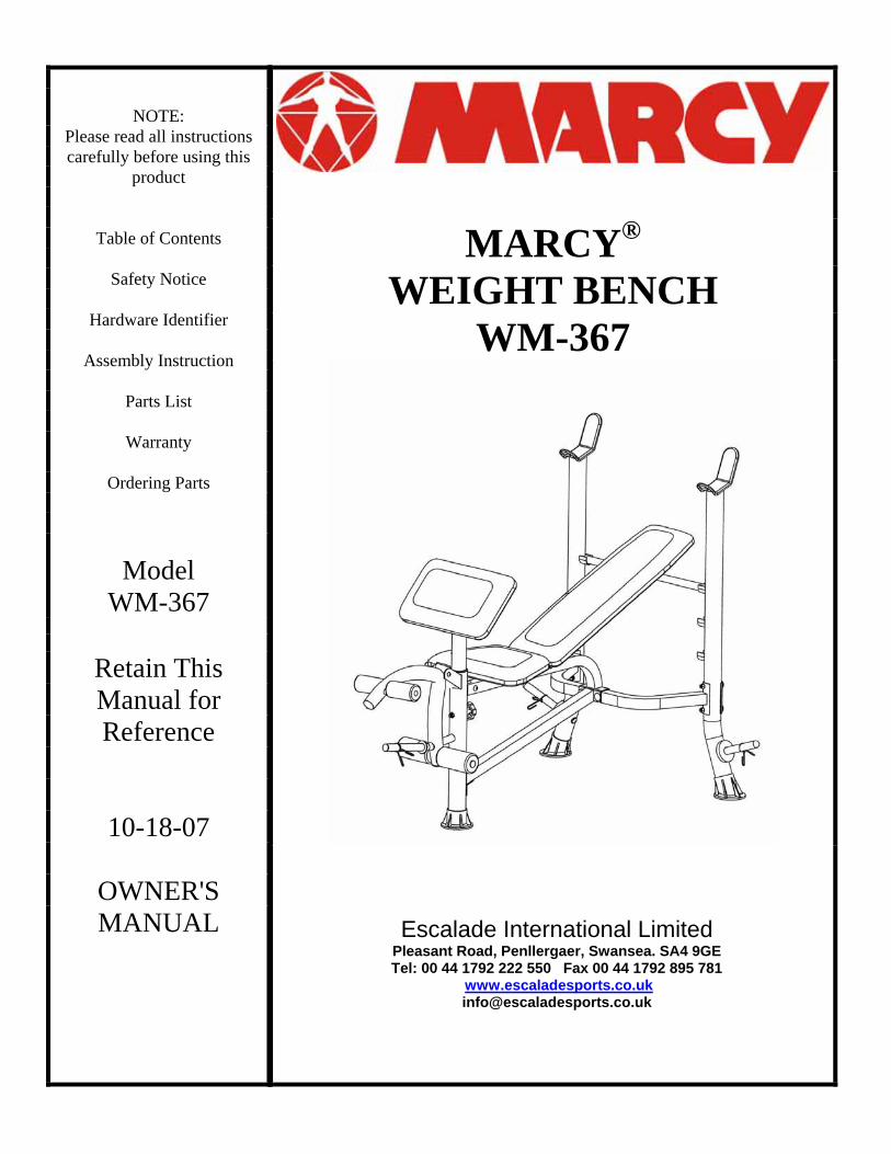
NOTE: Please read all instructions carefully before using this
product
Table of Contents
Safety Notice
Hardware Identifier
Assembly Instruction
Parts List
Warranty
Ordering Parts
Model WM-367
Retain This Manual for Reference
10-18-07
OWNER'S MANUAL
MARCY®
WEIGHT BENCH WM-367
Escalade International Limited Pleasant Road, Penllergaer, Swansea. SA4 9GE Tel: 00 44 1792 222 550 Fax 00 44 1792 895 781
TABLE OF CONTENTS BEFORE YOU BEGIN...................................................................................…. 1 IMPORTANT SAFETY NOTICES..................................................................…. 2 HARDWARE IDENTIFIER.....…....................................................................…. 4 ASSEMBLY INSTRUCTIONS........................................................................…. 5 EXPLODED DIAGRAM………………………………………………………………. 10 PARTS LIST...............................................................................................……. 11 WARRANTY.................................................................................................…. 12 ORDERING PARTS.......................................................................................… 12
BEFORE YOU BEGIN Thank you for selecting the MARCY WEIGHT BENCH by IMPEX FITNESS PRODUCTS. For your safety and benefit, read this manual carefully before using the machine. As the distributor, we are committed to provide you complete customer satisfaction. If you have any questions, or find there are missing or damaged parts or you require assistance assembling this product, we guarantee you complete satisfaction through direct assistance. To avoid unnecessary delays, please call our customer service department Monday to Friday 9am to 5pm.
Tel : 0044 (0) 1792 222 562
E mail: [email protected]
Supplied by Escalade International Ltd
Pleasant Road Penllergaer Swansea SA4 9GE
Tel: 00 44 1792 222550 Fax: 00 44 1792 895781
www.escaladesports.co.ukE mail: [email protected]
1
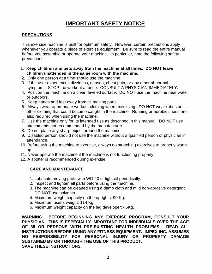
IMPORTANT SAFETY NOTICE PRECAUTIONS This exercise machine is built for optimum safety. However, certain precautions apply whenever you operate a piece of exercise equipment. Be sure to read the entire manual before you assemble or operate your machine. In particular, note the following safety precautions:
1. Keep children and pets away from the machine at all times. DO NOT leave children unattended in the same room with the machine.
2. Only one person at a time should use the machine. 3. If the user experiences dizziness, nausea, chest pain, or any other abnormal
symptoms, STOP the workout at once. CONSULT A PHYSICIAN IMMEDIATELY. 4. Position the machine on a clear, leveled surface. DO NOT use the machine near water
or outdoors. 5. Keep hands and feet away from all moving parts. 6. Always wear appropriate workout clothing when exercising. DO NOT wear robes or
other clothing that could become caught in the machine. Running or aerobic shoes are also required when using the machine.
7. Use the machine only for its intended use as described in this manual. DO NOT use attachments not recommended by the manufacturer.
8. Do not place any sharp object around the machine. 9. Disabled person should not use the machine without a qualified person or physician in
attendance. 10. Before using the machine to exercise, always do stretching exercises to properly warm
up. 11. Never operate the machine if the machine is not functioning properly. 12. A spotter is recommended during exercise.
CARE AND MAINTENANCE 1. Lubricate moving parts with WD-40 or light oil periodically. 2. Inspect and tighten all parts before using the machine. 3. The machine can be cleaned using a damp cloth and mild non-abrasive detergent. DO NOT use solvents. 4. Maximum weight capacity on the uprights: 90 Kg. 5. Maximum user’s weight: 114 Kg. 6. Maximum weight capacity on the leg developer: 45Kg.
WARNING: BEFORE BEGINNING ANY EXERCISE PROGRAM, CONSULT YOUR PHYSICIAN. THIS IS ESPECIALLY IMPORTANT FOR INDIVIDUALS OVER THE AGE OF 35 OR PERSONS WITH PRE-EXISTING HEALTH PROBLEMS. READ ALL INSTRUCTIONS BEFORE USING ANY FITNESS EQUIPMENT. IMPEX INC. ASSUMES NO RESPONSIBILITY FOR PERSONAL INJURY OR PROPERTY DAMAGE SUSTAINED BY OR THROUGH THE USE OF THIS PRODUCT. SAVE THESE INSTRUCTIONS.
2
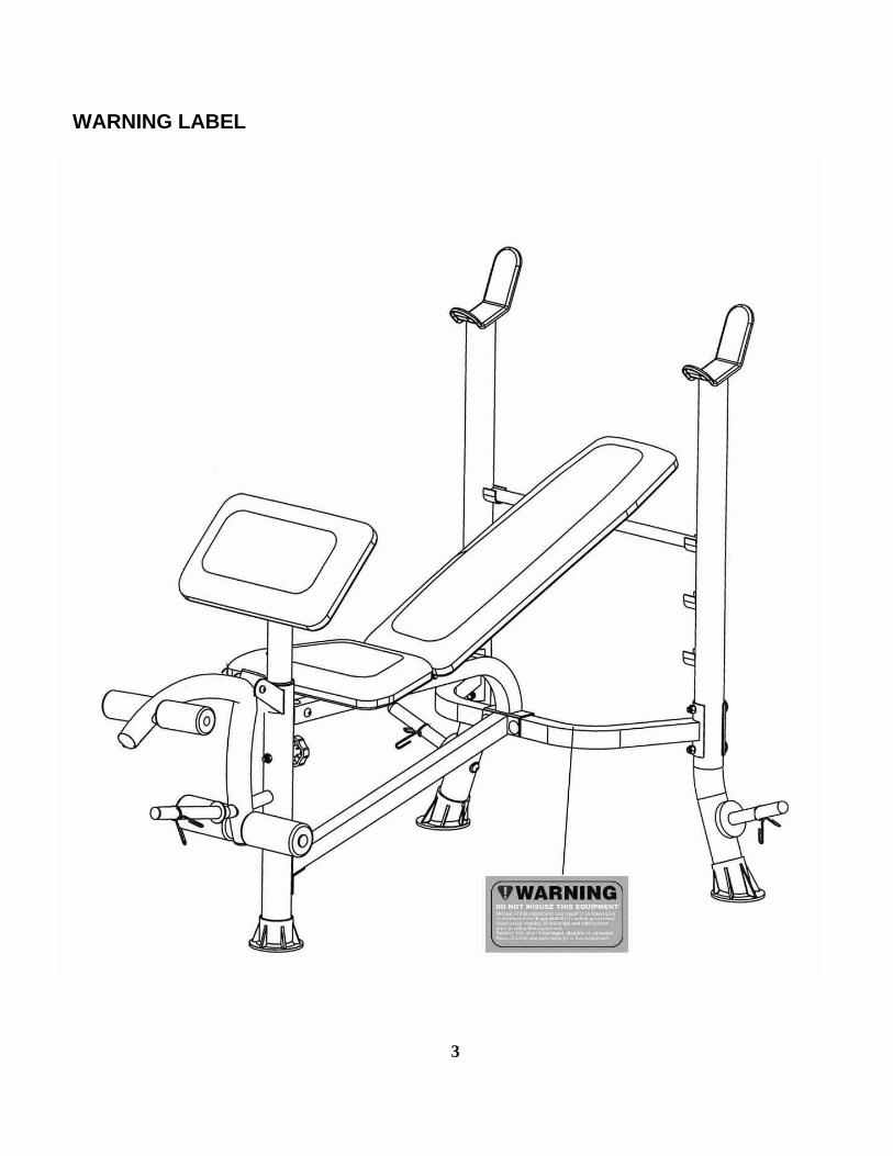
WARNING LABEL
3
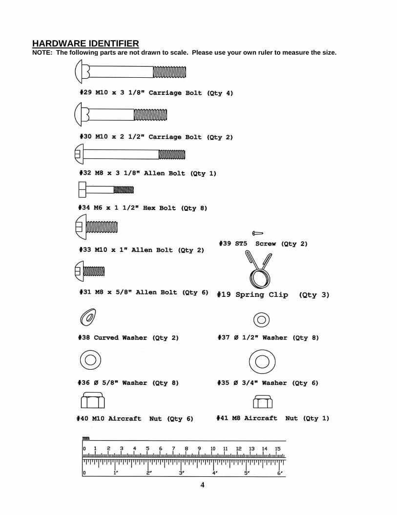
HARDWARE IDENTIFIER NOTE: The following parts are not drawn to scale. Please use your own ruler to measure the size.
4
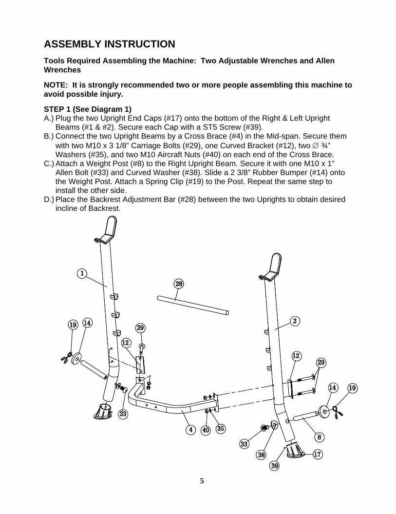
ASSEMBLY INSTRUCTION Tools Required Assembling the Machine: Two Adjustable Wrenches and Allen Wrenches
NOTE: It is strongly recommended two or more people assembling this machine to avoid possible injury.
STEP 1 (See Diagram 1) A.) Plug the two Upright End Caps (#17) onto the bottom of the Right & Left Upright
Beams (#1 & #2). Secure each Cap with a ST5 Screw (#39). B.) Connect the two Upright Beams by a Cross Brace (#4) in the Mid-span. Secure them
with two M10 x 3 1/8” Carriage Bolts (#29), one Curved Bracket (#12), two ∅ ¾” Washers (#35), and two M10 Aircraft Nuts (#40) on each end of the Cross Brace.
C.) Attach a Weight Post (#8) to the Right Upright Beam. Secure it with one M10 x 1” Allen Bolt (#33) and Curved Washer (#38). Slide a 2 3/8” Rubber Bumper (#14) onto the Weight Post. Attach a Spring Clip (#19) to the Post. Repeat the same step to install the other side.
D.) Place the Backrest Adjustment Bar (#28) between the two Uprights to obtain desired incline of Backrest.
5
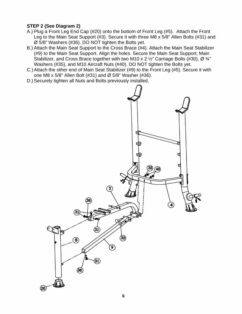
STEP 2 (See Diagram 2)
A.) Plug a Front Leg End Cap (#20) onto the bottom of Front Leg (#5). Attach the Front Leg to the Main Seat Support (#3). Secure it with three M8 x 5/8” Allen Bolts (#31) and Ø 5/8” Washers (#36). DO NOT tighten the Bolts yet.
B.) Attach the Main Seat Support to the Cross Brace (#4). Attach the Main Seat Stabilizer (#9) to the Main Seat Support. Align the holes. Secure the Main Seat Support, Main Stabilizer, and Cross Brace together with two M10 x 2 ½” Carriage Bolts (#30), Ø ¾” Washers (#35), and M10 Aircraft Nuts (#40). DO NOT tighten the Bolts yet.
C.) Attach the other end of Main Seat Stabilizer (#9) to the Front Leg (#5). Secure it with one M8 x 5/8” Allen Bolt (#31) and Ø 5/8” Washer (#36).
D.) Securely tighten all Nuts and Bolts previously installed.
6
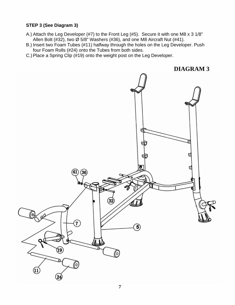
STEP 3 (See Diagram 3) A.) Attach the Leg Developer (#7) to the Front Leg (#5). Secure it with one M8 x 3 1/8”
Allen Bolt (#32), two Ø 5/8” Washers (#36), and one M8 Aircraft Nut (#41). B.) Insert two Foam Tubes (#11) halfway through the holes on the Leg Developer. Push
four Foam Rolls (#24) onto the Tubes from both sides. C.) Place a Spring Clip (#19) onto the weight post on the Leg Developer.
DIAGRAM 3
7
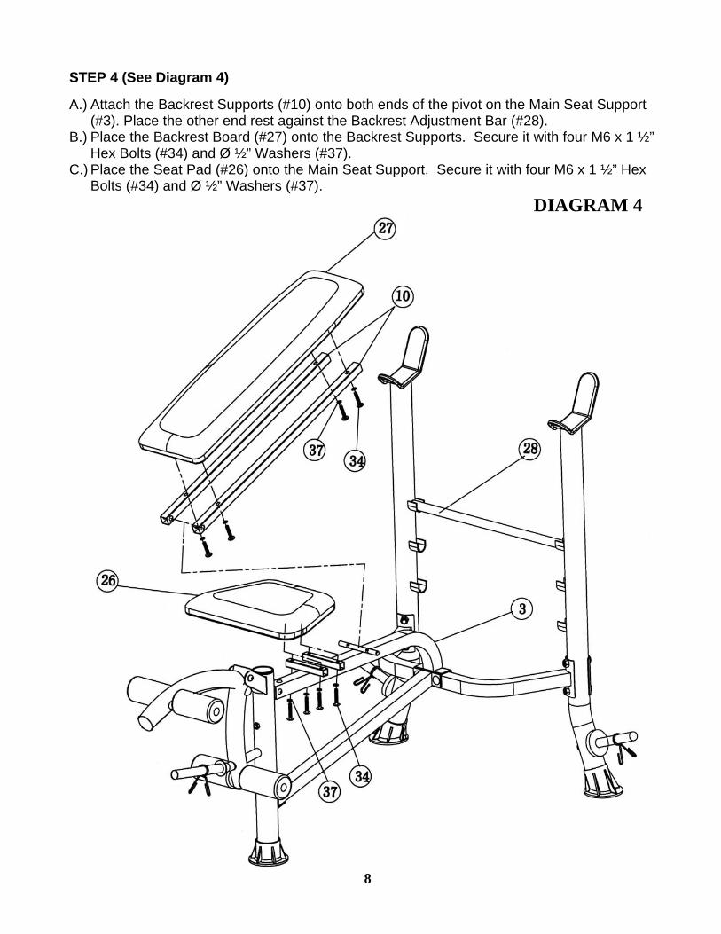
STEP 4 (See Diagram 4) A.) Attach the Backrest Supports (#10) onto both ends of the pivot on the Main Seat Support
(#3). Place the other end rest against the Backrest Adjustment Bar (#28). B.) Place the Backrest Board (#27) onto the Backrest Supports. Secure it with four M6 x 1 ½”
Hex Bolts (#34) and Ø ½” Washers (#37). C.) Place the Seat Pad (#26) onto the Main Seat Support. Secure it with four M6 x 1 ½” Hex
Bolts (#34) and Ø ½” Washers (#37). DIAGRAM 4
8
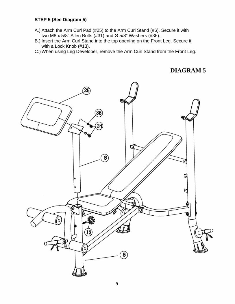
STEP 5 (See Diagram 5) A.) Attach the Arm Curl Pad (#25) to the Arm Curl Stand (#6). Secure it with
two M8 x 5/8” Allen Bolts (#31) and Ø 5/8” Washers (#36). B.) Insert the Arm Curl Stand into the top opening on the Front Leg. Secure it
with a Lock Knob (#13). C.) When using Leg Developer, remove the Arm Curl Stand from the Front Leg.
DIAGRAM 5
9
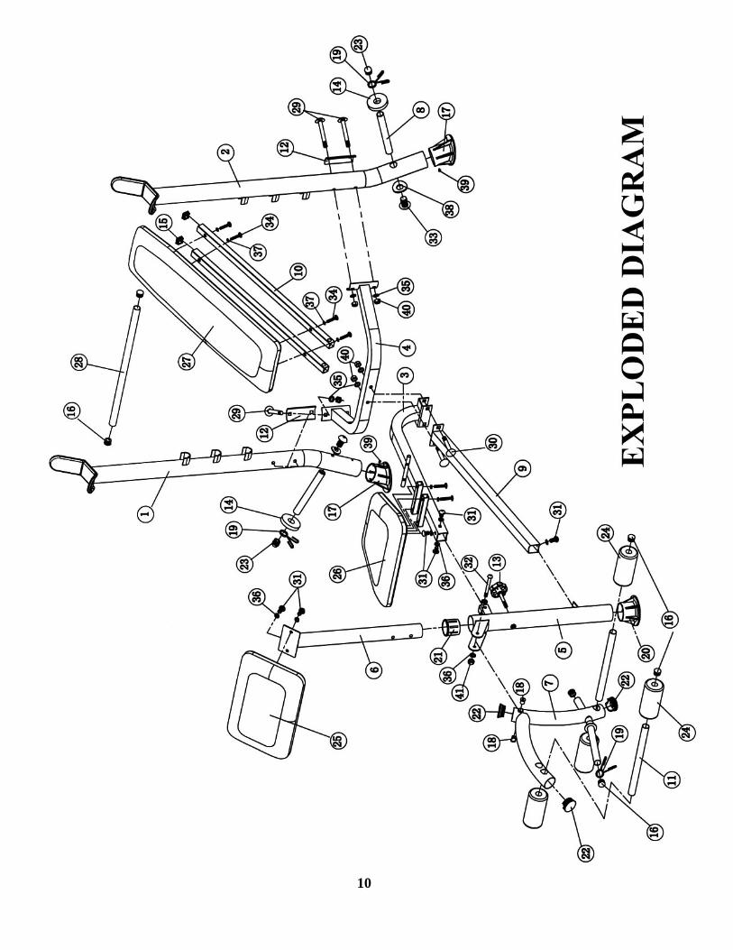
10
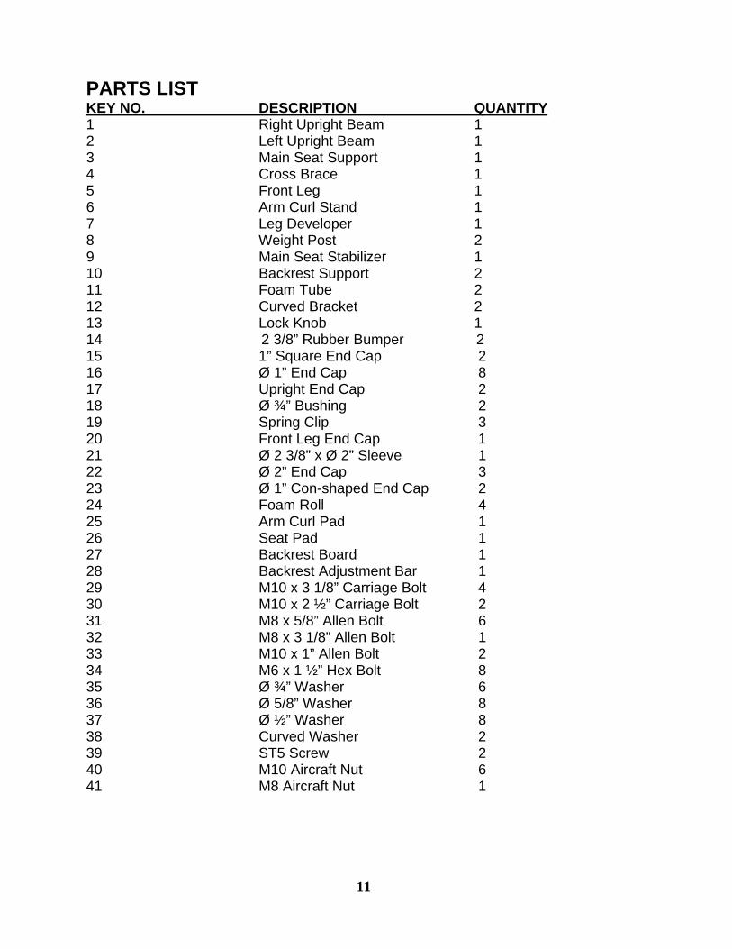
PARTS LIST KEY NO. DESCRIPTION QUANTITY 1 Right Upright Beam 1 2 Left Upright Beam 1 3 Main Seat Support 1 4 Cross Brace 1 5 Front Leg 1 6 Arm Curl Stand 1 7 Leg Developer 1 8 Weight Post 2 9 Main Seat Stabilizer 1 10 Backrest Support 2 11 Foam Tube 2 12 Curved Bracket 2 13 Lock Knob 1 14 2 3/8” Rubber Bumper 2 15 1” Square End Cap 2 16 Ø 1” End Cap 8 17 Upright End Cap 2 18 Ø ¾” Bushing 2 19 Spring Clip 3 20 Front Leg End Cap 1 21 Ø 2 3/8” x Ø 2” Sleeve 1 22 Ø 2” End Cap 3 23 Ø 1” Con-shaped End Cap 2 24 Foam Roll 4 25 Arm Curl Pad 1 26 Seat Pad 1 27 Backrest Board 1 28 Backrest Adjustment Bar 1 29 M10 x 3 1/8” Carriage Bolt 4 30 M10 x 2 ½” Carriage Bolt 2 31 M8 x 5/8” Allen Bolt 6 32 M8 x 3 1/8” Allen Bolt 1 33 M10 x 1” Allen Bolt 2 34 M6 x 1 ½” Hex Bolt 8 35 Ø ¾” Washer 6 36 Ø 5/8” Washer 8 37 Ø ½” Washer 8 38 Curved Washer 2 39 ST5 Screw 2 40 M10 Aircraft Nut 6 41 M8 Aircraft Nut 1
11

LIMITED WARRANTY
Escalade warrants this product to be free from defects in workmanship and material, under normal use and service conditions, for a period of two years on the frame and one year on all other parts and components from the date of purchase. This warranty extends only to the original purchaser. Escalade’s obligation under this Warranty is limited to replacing damaged or faulty parts at Escalade’s option. All returns must be pre-authorised by Escalade. This warranty does not extend to any product or damage to a product caused by or attributable to freight damage, abuse, misuse, improper or abnormal usage, purchasers own repairs or for products used for commercial or rental purposes. No other warranty beyond that specifically set forth above is authorized by Escalade. Escalade is not responsible or liable for indirect, special or consequential damages arising out of or in connection with the use or performance of the product or other damages with respect to any economic loss, loss of property, loss of revenues or profits, loss of enjoyments or use, costs of removal, installation or other consequential damages or whatsoever natures. The warranty extended hereunder is in lieu of any and all other warranties and any implied warranties of merchantability or fitness for a particular purpose is limited in its scope and duration to the terms set forth herein.
Your statutory rights are not affected.
ORDERING REPLACEMENT PARTS Replacement parts can be ordered by calling our Customer Service Department Monday to Friday 9am to 5pm.
Tel: 0044 (0) 1792 222 562 E mail: [email protected]
When ordering replacement parts, please give the following information. 1. Model 2. Description of Parts 3. Part Number 4. Date of Purchase
12

CARE AND MAINTENANCE 1. Inspect and tighten all parts before using the machine. 2. The machine can be cleaned using a damp cloth and mild non-
abrasive detergent. DO NOT use solvents. 3. Failure to examine the BENCH regularly may affect the safety
level of the equipment.