Embed Size (px)
Citation preview
Robotic Illustration
MARCUS WALLIN
Master of Science Thesis Stockholm, Sweden 2013

Robotic Illustration
Marcus Wallin
Master of Science Thesis MMK:2013:44 MCE 291 KTH Industrial Engineering and Management
Machine Design SE-100 44 STOCKHOLM

Examensarbete MMK:2013:44 MCE 291
Illustration med industrirobotar
Marcus Wallin
Godkänt
2013-06-12
Examinator
Sofia Ritzén
Handledare
Antonio Maffei, João Ferreira Uppdragsgivare
KTH Kontaktperson
Antonio Maffei
Sammanfattning Detta projekt åsyftade att möjliggöra för en industrirobot att illustrera godtyckliga digitala bilder på en plan yta. Detta uppnåddes genom att utrusta en manipulator med ett ritverktyg. Genom digital bildbehandling så kunde rörelsemönster genereras vilka matades till industriroboten för att den skulle kunna återskapa den digitala versionen. Roboten ritar med en teknik benämnd pointillism som innebär att endast punkter plottas. Resultatet blir en konkret svartvit representation av originalbilden.
Projektet genomfördes på institutionen Industriell Produktion på Kungliga Tekniska Högskolan. Projektet är i sin natur väldigt inriktat på forskning och utveckling eftersom det går ut på skapandet av en teknik för att uppnå ett tydligt mål. Kontinuerlig utveckling var kopplat till målet för att förbättra resultatet från olika aspekter.
Nyckelord: Industriell Robotteknik, Digital Bildbehandling, Optimering, Mekanisk Konstruktion, Kvalitetskontroll

Master of Science Thesis MMK:2013:44 MCE 291
Robotic Illustration
Marcus Wallin
Approved
2013-06-12
Examiner
Sofia Ritzén
Supervisors
Antonio Maffei, João Ferreira Commissioner
KTH Contact person
Antonio Maffei
Abstract This project strived to enable an industrial robot to illustrate arbitrary digitized images on a planar surface. This was accomplished by equipping a robotic manipulator with a drawing utensil. Motion patterns were generated based on digital image processing and fed to the robot for it to imitate the digital version. The robot prints with a technique called pointillism, which implies that solely points are plotted. The result is a tangible black and white representation of the original image.
The project was carried out in the Production Engineering facilities at the Royal Institute of Technology. The nature of the project is very research and development oriented as it deals with the creation of a technology to achieve an explicit goal. Continuous development was related to the goal to improve the result from different aspects.
Keywords: Industrial Robotics, Digital Image Processing, Optimization, Mechanical Design, Quality Control

TABLE OF CONTENTS 1 INTRODUCTION ................................................................................................................... 1
1.1 Project background ........................................................................................................... 1
1.2 Project description ............................................................................................................ 1
1.3 Purpose ............................................................................................................................. 2
1.4 Delimitations .................................................................................................................... 2
2 FRAME-OF-REFERENCE .................................................................................................... 5
2.1 Background research ........................................................................................................ 5
2.1.1 Research approach ................................................................................................................................. 5
2.1.2 Literature studies ................................................................................................................................... 5
2.1.3 Empirical studies .................................................................................................................................... 6
2.2 Requirements .................................................................................................................... 6
2.2.1 Project requirements .............................................................................................................................. 6
2.2.2 Project preferences ................................................................................................................................ 6
2.3 Risk assessment ................................................................................................................ 7
2.4 Lessons learned ................................................................................................................ 8
2.4.1 Offline robot simulation ......................................................................................................................... 8
2.4.2 Manual robot control ............................................................................................................................. 9
2.4.3 The RAPID programming language ...................................................................................................... 9
2.4.4 Mechanical workshop practice .............................................................................................................. 9
3 IMPLEMENTATION ........................................................................................................... 11
3.1 Methodology .................................................................................................................. 11
3.2 Planning .......................................................................................................................... 11
3.3 The setup ........................................................................................................................ 12
3.4 Activities ........................................................................................................................ 14
3.4.1 Robot programming ............................................................................................................................. 14
3.4.2 Image processing ................................................................................................................................. 16
3.4.3 Optimization ......................................................................................................................................... 17
3.4.4 Construction of a fixture ...................................................................................................................... 20
3.4.5 Surface arrangement ............................................................................................................................ 21
3.4.6 Choice of peripherals ........................................................................................................................... 21
4 RESULTS .............................................................................................................................. 23
4.1 The fixture ...................................................................................................................... 23
4.1.1 The first iteration .................................................................................................................................. 23
4.1.2 The second iteration ............................................................................................................................. 24
4.2 The surface ..................................................................................................................... 25
4.3 Quality assurance ........................................................................................................... 25
4.3.1 Repeatability test .................................................................................................................................. 25
4.3.2 Drawing simulation .............................................................................................................................. 27
4.4 Progress of drawings ...................................................................................................... 27
4.5 Optimization ................................................................................................................... 30
4.6 Performance benchmark ................................................................................................. 32
5 DISCUSSION ....................................................................................................................... 35
5.1 Continuation of the project ............................................................................................. 35
5.1.1 Surface optimization ............................................................................................................................. 35
5.2 Planning .......................................................................................................................... 37
5.3 Results ............................................................................................................................ 37
5.4 Sustainable development ................................................................................................ 38
5.4.1 Running cost estimation ....................................................................................................................... 38
5.5 Complications ................................................................................................................. 39
5.5.1 Uncalibrated robot ............................................................................................................................... 39
5.5.2 No RobotStudio license ........................................................................................................................ 39
5.5.3 Fragile equipment ................................................................................................................................ 40
5.5.4 Uneven surface ..................................................................................................................................... 40
5.5.5 Lag ........................................................................................................................................................ 40
5.5.6 Insufficient controller memory ............................................................................................................. 41
5.5.7 Delays on orders .................................................................................................................................. 41
5.5.8 The robot environment ......................................................................................................................... 42
5.5.9 Wear and tear of components .............................................................................................................. 42
5.5.10 Insufficient ink supply ........................................................................................................................ 42
5.5.11 Hampered ink discharge .................................................................................................................... 43
6 CONCLUSIONS ................................................................................................................... 45
REFERENCES ......................................................................................................................... 47
1
1 INTRODUCTION This chapter explains the background of the project and describes it in its entirety.
1.1 Project background This thesis was initiated from an idea devised by the respondent. To create a project appeared as more appealing in contrast to undertaking one. The freedom to define and run a project independently according to own liking was the most motivating factor for this decision as such opportunities proved to be rare throughout the education. The topic for this thesis was selected based upon interests of the respondent. Curiosity drove a merge between different areas that are not generally associated with each other to create something tangible and to investigate what kind of results can be accomplished. Earlier experiences in these areas were acquired during a similar bachelor thesis, and the result suggested that an extension of this concept would be appropriate to effect new results. The outcome is closely dependent on the equipment used and since sophisticated gear is accessible for this project, it allows for advanced tasks and high precision. The project is very well suited for the academic background and experiences of the respondent.
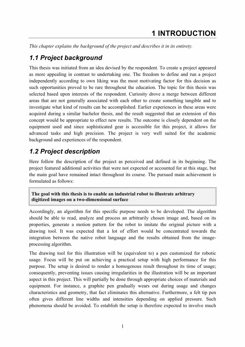
1.2 Project description Here follow the description of the project as perceived and defined in its beginning. The project featured additional activities that were not expected or accounted for at this stage, but the main goal have remained intact throughout its course. The pursued main achievement is formulated as follows:
The goal with this thesis is to enable an industrial robot to illustrate arbitrary digitized images on a two-dimensional surface
Accordingly, an algorithm for this specific purpose needs to be developed. The algorithm should be able to read, analyze and process an arbitrarily chosen image and, based on its properties, generate a motion pattern for the robot to imitate the original picture with a drawing tool. It was expected that a lot of effort would be concentrated towards the integration between the native robot language and the results obtained from the image-processing algorithm.
The drawing tool for this illustration will be (equivalent to) a pen customized for robotic usage. Focus will be put on achieving a practical setup with high performance for this purpose. The setup is desired to render a homogenous result throughout its time of usage; consequently, preventing issues causing irregularities in the illustration will be an important aspect in this project. This will partially be done through appropriate choices of materials and equipment. For instance, a graphite pen gradually wears out during usage and changes characteristics and geometry, that fact eliminates this alternative. Furthermore, a felt tip pen often gives different line widths and intensities depending on applied pressure. Such phenomena should be avoided. To establish the setup is therefore expected to involve much
2
experimental testing to identify suitable tools, methods, materials and mechanisms in order to achieve a good result.
The quantity of the data generated by the image processing software will be significant and this introduces a large optimization problem. The working method of the robot should be optimized in order to minimize the time consumption needed to complete a process. The robot must move in continuous and efficient ways and preferably take the shortest paths. Since the instructions for the robot is not a repetitive cycle, it needs to be executed in a logical and time saving order. Effort will furthermore be put on achieving a high performing system in terms of speed.
1.3 Purpose This report strives to answer how the goal can be accomplished and serves as documentation where everything of significance to the project is noted and explained. The aim is to present the project in a way that can be easily followed and understood by readers without previous subject knowledge or insight into the project.
1.4 Delimitations The goal is indeed very broadly defined and can thus be accomplished in many different ways; therefore the project is naturally narrowed down to one specific way to reach it. This project is essentially a merge between engineering and art as domains. This means that the project can likewise be evaluated from an artistic point of view. However, this project will naturally tend to focus more on the engineering aspects to prove the technology, as this is the core of the education and the environment. This means that the appearance of the result may suffer slightly as the technical aspects are principally prioritized in the project.
The time consumption for every item in this project is hard to estimate as few activities builds on earlier routines. Some simplifications are to be made to facilitate reaching the goal of the project. Several options of how to expand the work are proposed that will be considered if and when time allows for it. The following limitations in Table 1 were formulated in the early stages of the project.
3
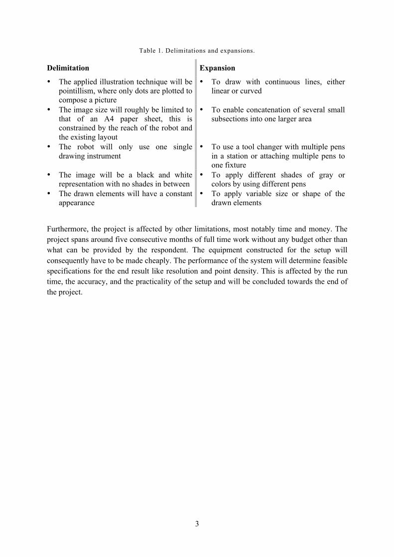
Table 1. Delimitations and expansions.
Delimitation Expansion
• The applied illustration technique will be pointillism, where only dots are plotted to compose a picture
• To draw with continuous lines, either linear or curved
• The image size will roughly be limited to that of an A4 paper sheet, this is constrained by the reach of the robot and the existing layout
• To enable concatenation of several small subsections into one larger area
• The robot will only use one single drawing instrument
• To use a tool changer with multiple pens in a station or attaching multiple pens to one fixture
• The image will be a black and white representation with no shades in between
• To apply different shades of gray or colors by using different pens
• The drawn elements will have a constant appearance
• To apply variable size or shape of the drawn elements
Furthermore, the project is affected by other limitations, most notably time and money. The project spans around five consecutive months of full time work without any budget other than what can be provided by the respondent. The equipment constructed for the setup will consequently have to be made cheaply. The performance of the system will determine feasible specifications for the end result like resolution and point density. This is affected by the run time, the accuracy, and the practicality of the setup and will be concluded towards the end of the project.

4
5
2 FRAME-OF-REFERENCE This chapter explains the background research done in the project, the requirements, the risks and some lessons learned.
2.1 Background research A solid knowledge base and know-how in multiple areas needed to be acquired prior to the execution of some tasks. Research was also necessary in order to choose appropriate procedures in the project. To obtain necessary knowledge was primarily done by reading selected documentations. No careful planning was done regarding the studies, they were essentially carried out after recognizing their actual need in some area.
The project is not dependent on any earlier work in any area, nor does it concern improvements of a product or a technology in any aspect. Rather, it does only concern creation and development of a technology from scratch. This means that the references needed to progress with this project will be few as most of the knowledge and content will originate from the respondent. Most of the research consisted of acquiring applicable knowledge and skills within programming, relevant software and machine handling, material and component choices. The background research will therefore mostly concern these areas. The background research will also focus on identifying feasible ways to reach the goal with respect to the means available.
2.1.1 Research approach Background research will be performed as when needed to execute a task. This will be done in conjunction with progressive work. To do all research at once would be a loss as it is difficult to predict exactly which knowledge will be needed throughout the entire project, and which will not. It would also be harder to focus on several areas at once and to memorize all findings for later usage; to stepwise break up one task is a more efficient approach. Therefore, the actual research will be scattered throughout the project.
2.1.2 Literature studies Most of the research will be done in the beginning, as much knowledge must be obtained regarding usage of the equipment. The subject matter for these studies will mainly consist of the official product documentations provided by ABB for the actual robot system. Several manuals will be consulted, among the most important, that of the native robot programming language RAPID (1), the software RobotStudio (2), and the online robot controlling via the teach pendant (3), a handheld joystick device.
The image processing will be done in the MATLAB software environment. This utility features a wide documentation online where answers to most programming related tasks could be found. This will be consulted as when needed; no dedicated literature on the subject was initially expected to be necessary.
6
2.1.3 Empirical studies Learning to drive a car by studying literature is not a very effective way to acquire such skills in practice, and it works in the same way with robots. To control a robot requires hands-on experience to get a sense of how it works and how to control it. The robot can be controlled manually using its teach pendant. Although there is documentation for this device explaining its every function, it proved to be more efficient to learn it by trying since it is quite intuitive. The documentation is better used as a reference to check on how to access specific functions when needed.
Further empirical studies are also relevant at later stages as the project progresses, for instance, to investigate appropriate materials or different drawing utensils to be utilized in the final setup. Such things are hard to predict with theoretical research and must therefore be tested instead. This is considered as refining work and is not core to achieving the goal. This is furthermore not regarded as very engineering intensive work, so it will consequently have a lower priority.
2.2 Requirements The project is not subject to any external requirements other than those mandatory for every master thesis originating from the Machine Design department (4), most notably a specific layout and structure of the documentation. However, additional requirements were perceived as relevant for this specific project, a compilation of those was formulated by the respondent. The list is divided into requirements, which can be either accomplished or not, and preferences, which are measurable or subjectively assessed characteristics. Though, no explicit numeric values are required for the latter, only the directions of the priorities are indicated.
2.2.1 Project requirements • Achieve a working setup that satisfies the goal
• Design and manufacture a custom fixture for a drawing utensil to attach to the robot • Write an algorithm for processing of any image and generation of coordinates • Implement data conversion to robotic movements • Optimize the robot movements in order to save time • Testing, benchmarking and evaluation to conclude performance and improvements
2.2.2 Project preferences • Little monitoring and maintenance time required to run the setup • Few possible reoccurring errors during the operation of the setup • High resolution of picture • Large image area • Low average cycle time • Accurate image representation • Qualitative artistic and homogenous result
7
In addition to this, several features (in software or hardware) may prove to be necessary or wanted in order to achieve the listed requirements. Furthermore, there are many sub goals related to the tasks performed. Several requirements were also necessary for the mechanical parts that were constructed. These requirements are discussed in the sections concerning each mechanical component.
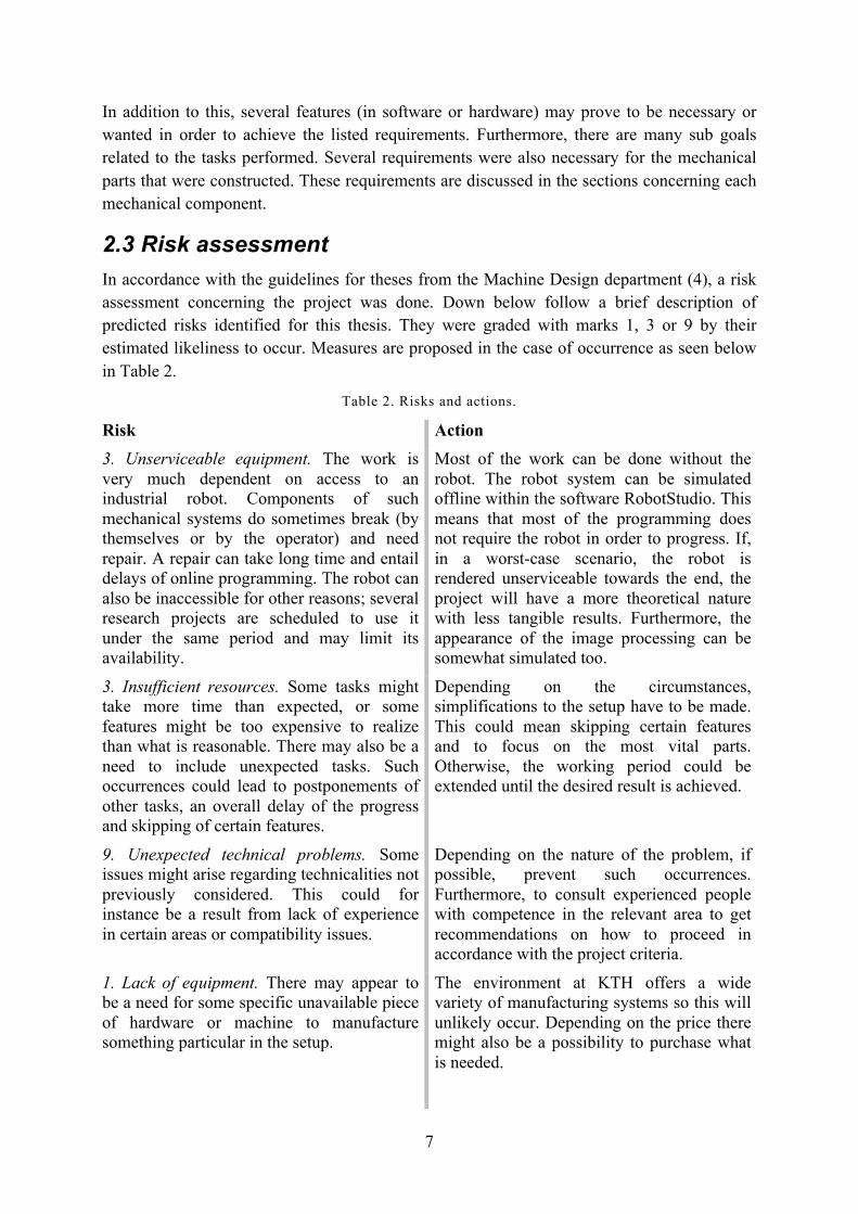
2.3 Risk assessment In accordance with the guidelines for theses from the Machine Design department (4), a risk assessment concerning the project was done. Down below follow a brief description of predicted risks identified for this thesis. They were graded with marks 1, 3 or 9 by their estimated likeliness to occur. Measures are proposed in the case of occurrence as seen below in Table 2.
Table 2. Risks and actions.
Risk Action 3. Unserviceable equipment. The work is very much dependent on access to an industrial robot. Components of such mechanical systems do sometimes break (by themselves or by the operator) and need repair. A repair can take long time and entail delays of online programming. The robot can also be inaccessible for other reasons; several research projects are scheduled to use it under the same period and may limit its availability.
Most of the work can be done without the robot. The robot system can be simulated offline within the software RobotStudio. This means that most of the programming does not require the robot in order to progress. If, in a worst-case scenario, the robot is rendered unserviceable towards the end, the project will have a more theoretical nature with less tangible results. Furthermore, the appearance of the image processing can be somewhat simulated too.
3. Insufficient resources. Some tasks might take more time than expected, or some features might be too expensive to realize than what is reasonable. There may also be a need to include unexpected tasks. Such occurrences could lead to postponements of other tasks, an overall delay of the progress and skipping of certain features.
Depending on the circumstances, simplifications to the setup have to be made. This could mean skipping certain features and to focus on the most vital parts. Otherwise, the working period could be extended until the desired result is achieved.
9. Unexpected technical problems. Some issues might arise regarding technicalities not previously considered. This could for instance be a result from lack of experience in certain areas or compatibility issues.
Depending on the nature of the problem, if possible, prevent such occurrences. Furthermore, to consult experienced people with competence in the relevant area to get recommendations on how to proceed in accordance with the project criteria.
1. Lack of equipment. There may appear to be a need for some specific unavailable piece of hardware or machine to manufacture something particular in the setup.
The environment at KTH offers a wide variety of manufacturing systems so this will unlikely occur. Depending on the price there might also be a possibility to purchase what is needed.
8
3. Problems related to large data sets. The data might prove to be too much to process or be too difficult to handle in an efficient way.
Even if not the true optimal ways can be found, there can still be many improvements of performance made in this area.
9. Other. All of the problems that do not fit into any other category.
Depends on the nature of the problem.
2.4 Lessons learned Here follow a compilation of the essential lessons learned during the studies.
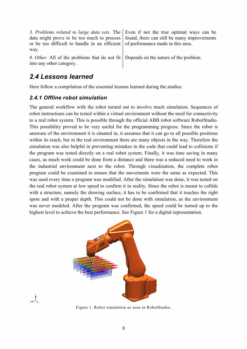
2.4.1 Offline robot simulation The general workflow with the robot turned out to involve much simulation. Sequences of robot instructions can be tested within a virtual environment without the need for connectivity to a real robot system. This is possible through the official ABB robot software RobotStudio. This possibility proved to be very useful for the programming progress. Since the robot is unaware of the environment it is situated in, it assumes that it can go to all possible positions within its reach, but in the real environment there are many objects in the way. Therefore the simulation was also helpful in preventing mistakes in the code that could lead to collisions if the program was tested directly on a real robot system. Finally, it was time saving in many cases, as much work could be done from a distance and there was a reduced need to work in the industrial environment next to the robot. Through visualization, the complete robot program could be examined to ensure that the movements were the same as expected. This was used every time a program was modified. After the simulation was done, it was tested on the real robot system at low speed to confirm it in reality. Since the robot is meant to collide with a structure, namely the drawing surface, it has to be confirmed that it touches the right spots and with a proper depth. This could not be done with simulation, as the environment was never modeled. After the program was confirmed, the speed could be turned up to the highest level to achieve the best performance. See Figure 1 for a digital representation.
Figure 1. Robot simulation as seen in RobotStudio.
9
In this illustration, a test path with multiple targets is visualized in an evenly distributed grid. Coordinate systems are shown for the global environment, the local working area, and all the targets specified in the path.
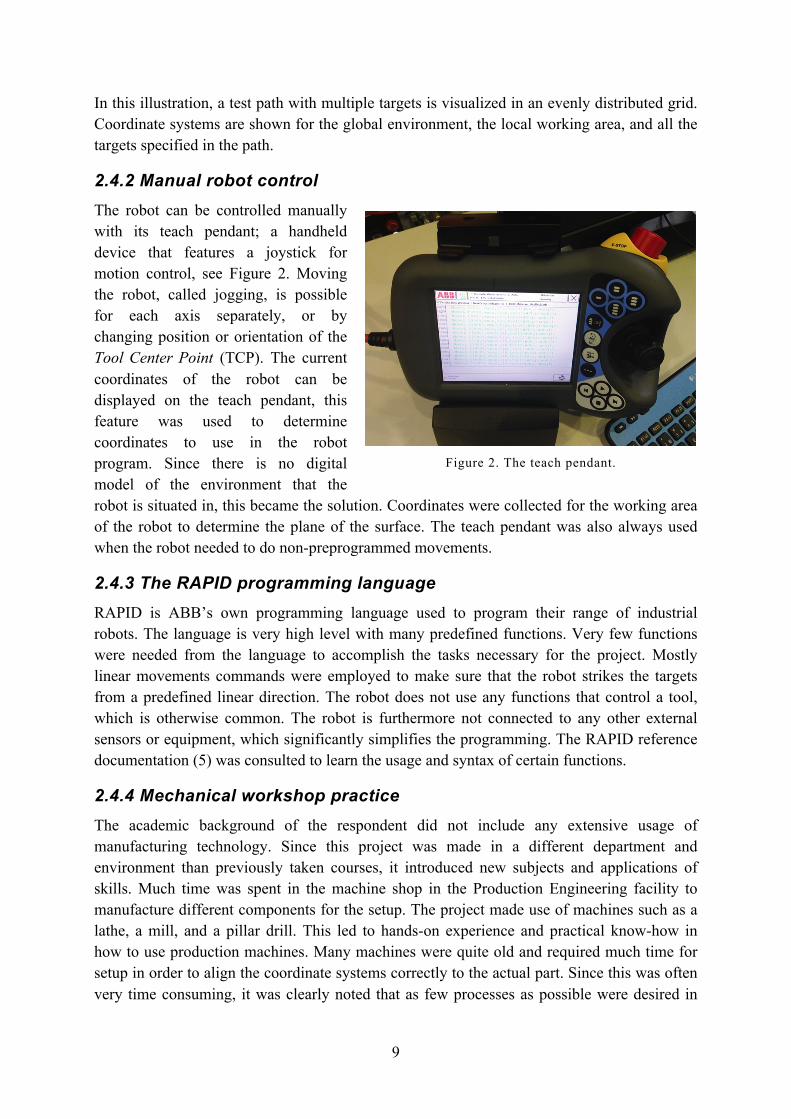
2.4.2 Manual robot control The robot can be controlled manually with its teach pendant; a handheld device that features a joystick for motion control, see Figure 2. Moving the robot, called jogging, is possible for each axis separately, or by changing position or orientation of the Tool Center Point (TCP). The current coordinates of the robot can be displayed on the teach pendant, this feature was used to determine coordinates to use in the robot program. Since there is no digital model of the environment that the robot is situated in, this became the solution. Coordinates were collected for the working area of the robot to determine the plane of the surface. The teach pendant was also always used when the robot needed to do non-preprogrammed movements.
2.4.3 The RAPID programming language RAPID is ABB’s own programming language used to program their range of industrial robots. The language is very high level with many predefined functions. Very few functions were needed from the language to accomplish the tasks necessary for the project. Mostly linear movements commands were employed to make sure that the robot strikes the targets from a predefined linear direction. The robot does not use any functions that control a tool, which is otherwise common. The robot is furthermore not connected to any other external sensors or equipment, which significantly simplifies the programming. The RAPID reference documentation (5) was consulted to learn the usage and syntax of certain functions.
2.4.4 Mechanical workshop practice The academic background of the respondent did not include any extensive usage of manufacturing technology. Since this project was made in a different department and environment than previously taken courses, it introduced new subjects and applications of skills. Much time was spent in the machine shop in the Production Engineering facility to manufacture different components for the setup. The project made use of machines such as a lathe, a mill, and a pillar drill. This led to hands-on experience and practical know-how in how to use production machines. Many machines were quite old and required much time for setup in order to align the coordinate systems correctly to the actual part. Since this was often very time consuming, it was clearly noted that as few processes as possible were desired in
Figure 2. The teach pendant.
10
order to save time during the manufacturing. This gave many insights in how to design components better in order to manufacture them quicker.
11
3 IMPLEMENTATION The progress of the project is described in this chapter. The methods used and the theory behind every aspect is explained.
3.1 Methodology The project did not strive to realize perfect solutions from the beginning. Applying this method will increase risk and the possibility to oversee obstacles that can cause more severe problems at later stages of the project. Instead, the project started with the simplest possible solutions, and then focused on making them more advanced and reliable along the course of the project until the desired results were achieved. Thus, multiple iterations of fixtures, setups, and software were done when proved necessary. The working method circled around an incremental improvement approach, where the need for improvements was mainly discovered by practical usage. Many decisions in the project were often being done according to intuition and sense of propriety without thorough calculations or evaluations; this was to faster reach specific results.
The appearance of the product is difficult to predict. It can be evaluated both objectively with numbers and subjectively with personal preferences. This work is expected to involve much experimental testing in order to achieve a subjectively appealing result. However, the aim is to prove the technology rather than achieving a result according to some numerical specifications, while that may become a strong preference, it is not part of the core of this project.
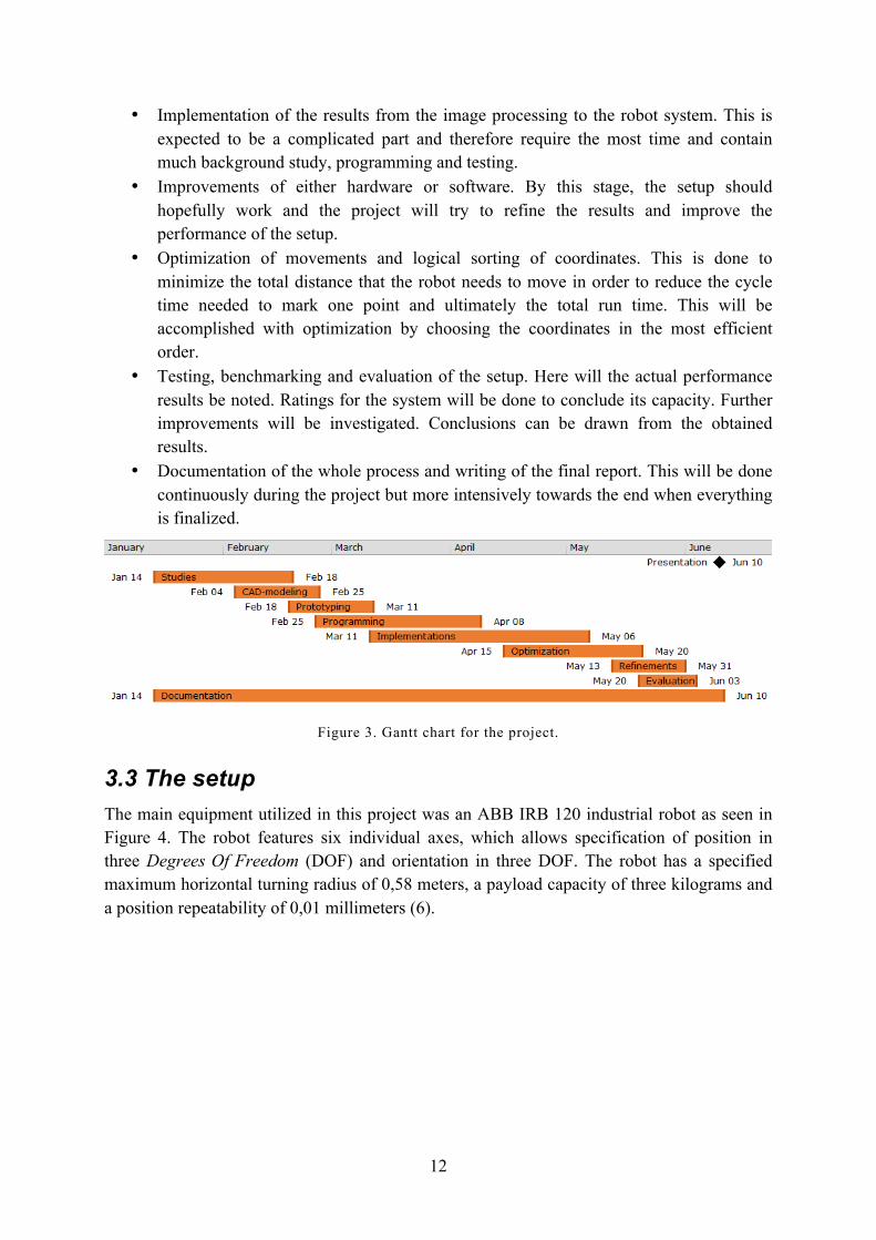
3.2 Planning Here follow the preliminary planning established in the beginning of the project. The known necessary activities are planned for in the project. A brief description is given to what every item implies and a motivation declares why they are included. The time required for every step is estimated and the order of all activities is defined. Some tasks will be done in parallel. The project is assumed to span 20 consecutive weeks of full time work. A Gantt chart is used to visualize the process, see Figure 3.
• Studies of both relevant literature and experimental testing will be done to learn more about usage of the current robot system. The knowledge acquired is necessary to adapt software to the robot system. Studies of suitable drawing utensils and materials will also be done.
• Design of the fixture to mount the drawing utensil. This will concern examination of the current robot interface and the geometry of the drawing utensil. A design that is light, rigid and easy to manufacture will be done.
• Prototyping of the fixture will be done in a 3D printer. This will also require assembly of different parts; the pen may need a spring mechanism to allow some flexibility. A version in aluminum will also possibly be made.
• Programming of the image-processing algorithm. The algorithm is intended to produce a (long) list of coordinates for the robot to use in order to illustrate the actual image.
12
• Implementation of the results from the image processing to the robot system. This is expected to be a complicated part and therefore require the most time and contain much background study, programming and testing.
• Improvements of either hardware or software. By this stage, the setup should hopefully work and the project will try to refine the results and improve the performance of the setup.
• Optimization of movements and logical sorting of coordinates. This is done to minimize the total distance that the robot needs to move in order to reduce the cycle time needed to mark one point and ultimately the total run time. This will be accomplished with optimization by choosing the coordinates in the most efficient order.
• Testing, benchmarking and evaluation of the setup. Here will the actual performance results be noted. Ratings for the system will be done to conclude its capacity. Further improvements will be investigated. Conclusions can be drawn from the obtained results.
• Documentation of the whole process and writing of the final report. This will be done continuously during the project but more intensively towards the end when everything is finalized.
Figure 3. Gantt chart for the project.
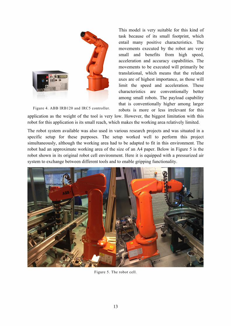
3.3 The setup The main equipment utilized in this project was an ABB IRB 120 industrial robot as seen in Figure 4. The robot features six individual axes, which allows specification of position in three Degrees Of Freedom (DOF) and orientation in three DOF. The robot has a specified maximum horizontal turning radius of 0,58 meters, a payload capacity of three kilograms and a position repeatability of 0,01 millimeters (6).
13
This model is very suitable for this kind of task because of its small footprint, which entail many positive characteristics. The movements executed by the robot are very small and benefits from high speed, acceleration and accuracy capabilities. The movements to be executed will primarily be translational, which means that the related axes are of highest importance, as those will limit the speed and acceleration. These characteristics are conventionally better among small robots. The payload capability that is conventionally higher among larger robots is more or less irrelevant for this
application as the weight of the tool is very low. However, the biggest limitation with this robot for this application is its small reach, which makes the working area relatively limited.
The robot system available was also used in various research projects and was situated in a specific setup for these purposes. The setup worked well to perform this project simultaneously, although the working area had to be adapted to fit in this environment. The robot had an approximate working area of the size of an A4 paper. Below in Figure 5 is the robot shown in its original robot cell environment. Here it is equipped with a pressurized air system to exchange between different tools and to enable gripping functionality.
Figure 5. The robot cell.
Figure 4. ABB IRB120 and IRC5 controller.
14
3.4 Activities Here are the key-steps explained that were executed in order to achieve the goal. Most of the development done in the project is presented here.
3.4.1 Robot programming Since the robot is only equipped with one drawing utensil, it will make one dot at each strike. To make dots on a surface, the robot is intended to strike the surface from an orientation parallel to the normal to that surface to make the dots as uniform as possible. The surface is approximately placed in a horizontal plane, this is done to facilitate the ink flow in the pen, as it works best when gravity pushes it downwards; held at a slight angle to the vertical, the pen does not give any ink discharge upon contact with a surface. The robot should then move linearly along the direction of the normal until it hits the surface. First the plane of the working area needed to be determined, this was done by identifying three coordinates on that surface. Linear Algebra was then used to determine a normal of the plane. First, three arbitrary coordinates on the surface were noted:
𝑝! = 𝑥!,𝑦!, 𝑧! (A1)
𝑝! = 𝑥!,𝑦!, 𝑧! (A2)
𝑝! = 𝑥!,𝑦!, 𝑧! (A3)
Two vectors in that plane were then calculated accordingly:
𝒗𝟏 = 𝑝! − 𝑝! = 𝑥! − 𝑥!,𝑦! − 𝑦!, 𝑧! − 𝑧! = 𝑎!,𝑎!,𝑎! (A4)
𝒗𝟐 = 𝑝! − 𝑝! = 𝑥! − 𝑥!,𝑦! − 𝑦!, 𝑧! − 𝑧! = 𝑏!, 𝑏!, 𝑏! (A5)
The cross product of these two vectors is utilized to identify the normal of the plane:
𝒁 = 𝒗𝟏×𝒗𝟐 =𝑎!𝑏! − 𝑎!𝑏!𝑎!𝑏! − 𝑎!𝑏!𝑎!𝑏! − 𝑎!𝑏!
(A6)
When the normal was found, it could be used to define the plane of the surface and the direction of the robot tool. During the whole program with the robot, the orientation of the tool was kept constant, as there is never any need to alter it. When moving the robot from one (painted) point to the next one, the robot was programmed to move in a continuous fashion and to not stop anywhere in between in order to save time. Obviously the robot needed to stop at every point that it paints in order to reverse the direction of the movement.
3.4.1.1 Coordinate system transformation
When modeling an environment in the computer, it is easy to determine the exact geometry and placement of all objects. To create an exact replica in reality of a digital model, or vice versa, is much more complicated. Instead of making this attempt, some steps were taken to adapt the robot to its current environment. One of these things was a transformation of
15
coordinate systems. The robot system incorporates several coordinate systems, by default one global coordinate system that everything is related to, and an additional coordinate system for the tool. Apart from those, it proved to be beneficial to add a new coordinate system for the working area to relate all movements to instead. It simplified the programming significantly and made it easier to change the program if the environment is altered.
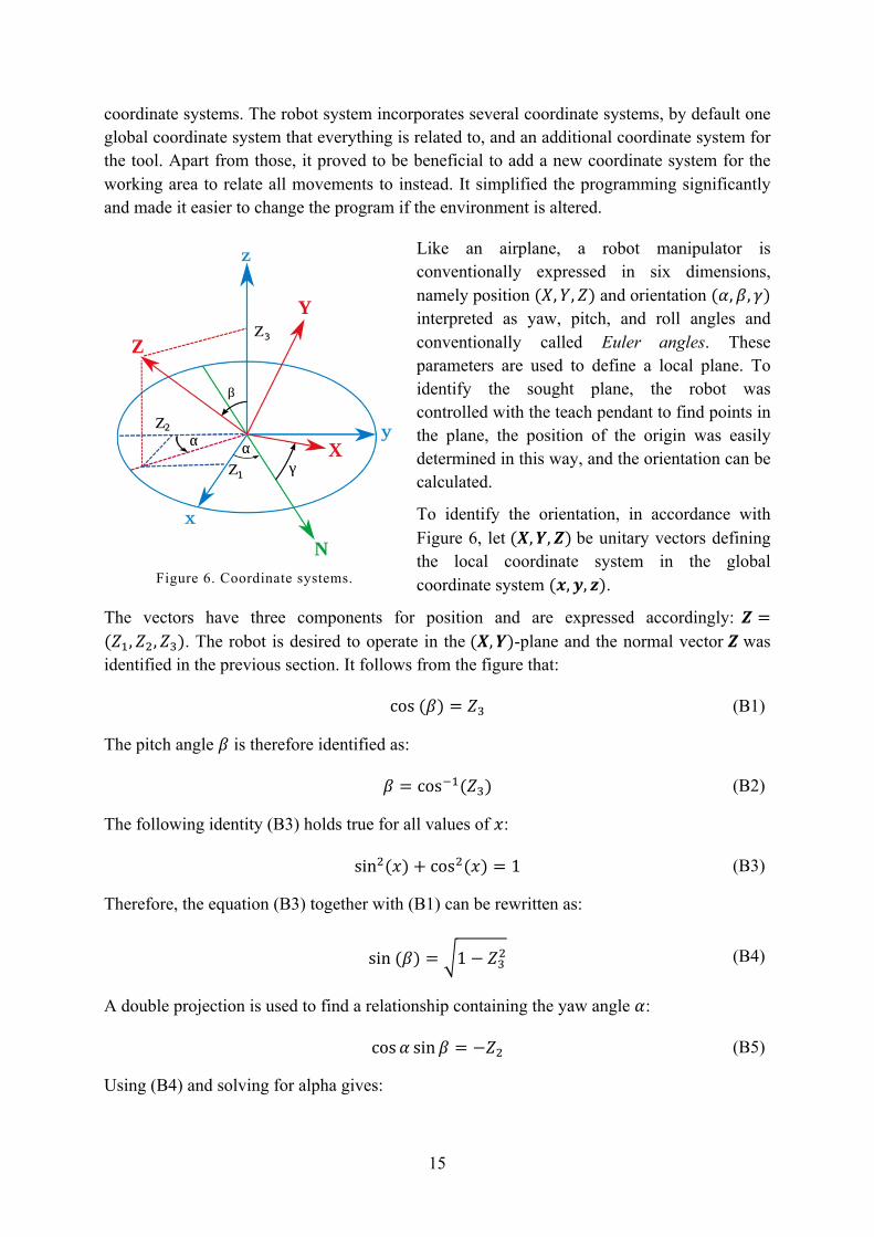
Like an airplane, a robot manipulator is conventionally expressed in six dimensions, namely position (𝑋,𝑌,𝑍) and orientation (𝛼,𝛽, 𝛾) interpreted as yaw, pitch, and roll angles and conventionally called Euler angles. These parameters are used to define a local plane. To identify the sought plane, the robot was controlled with the teach pendant to find points in the plane, the position of the origin was easily determined in this way, and the orientation can be calculated.
To identify the orientation, in accordance with Figure 6, let (𝑿,𝒀,𝒁) be unitary vectors defining the local coordinate system in the global coordinate system (𝒙,𝒚, 𝒛).
The vectors have three components for position and are expressed accordingly: 𝒁 =(𝑍!,𝑍!,𝑍!). The robot is desired to operate in the (𝑿,𝒀)-plane and the normal vector 𝒁 was identified in the previous section. It follows from the figure that:
cos (𝛽) = 𝑍! (B1)
The pitch angle 𝛽 is therefore identified as:
𝛽 = cos!!(𝑍!) (B2)
The following identity (B3) holds true for all values of 𝑥:
sin!(𝑥)+ cos!(𝑥) = 1 (B3)
Therefore, the equation (B3) together with (B1) can be rewritten as:
sin (𝛽) = 1− 𝑍!! (B4)
A double projection is used to find a relationship containing the yaw angle 𝛼:
cos𝛼 sin𝛽 = −𝑍! (B5)
Using (B4) and solving for alpha gives:
Figure 6. Coordinate systems.
16
𝛼 = cos!!(−𝑍! 1− 𝑍!!) (B6)
The roll angle 𝛾 is a free variable independent of the plane. This is chosen based on the alignment on the work object. For this setup it is set to zero.
3.4.1.2 Translation to quaternions
The concluded data is used to define the coordinate system. However, this robot system does not utilize Euler angles to define orientation, it uses the concept of quaternions instead. The quaternions are hard to interpret so therefore the identification of Euler angles was necessary in order to do a translation instead of finding the quaternions directly.
A unit quaternion is a set of four parameters with the following properties:
𝒒 = 𝑞! 𝑞! 𝑞! 𝑞! ! (C1)
𝒒 ! = 𝑞!! + 𝑞!! + 𝑞!! + 𝑞!! = 1 (C2)
Euler angles can be translated into quaternions with the following expression:
𝒒 =
cos 𝛾 2 cos 𝛽 2 cos 𝛼 2 + sin 𝛾 2 sin 𝛽 2 sin 𝛼 2sin 𝛾 2 cos 𝛽 2 cos 𝛼 2 − cos 𝛾 2 sin 𝛽 2 sin 𝛼 2cos 𝛾 2 sin 𝛽 2 cos 𝛼 2 + sin 𝛾 2 cos 𝛽 2 sin 𝛼 2cos 𝛾 2 cos 𝛽 2 sin 𝛼 2 − sin 𝛾 2 sin 𝛽 2 cos 𝛼 2
(C3)
The same information is used to define the orientation of the manipulator in relation to the plane.
3.4.2 Image processing Since the illustration is based on a single drawing utensil with constant intensity, it is clear that different shades of gray cannot be achieved to imitate the original image. The perception of a gray scale is instead accomplished by varying the dot densities in different areas. Accordingly, since the project will use a plain white background and black ink, in a dark area of the image, more dots are painted in a given space and vice versa.
The first thing done in the image processing is to convert the image into gray scale because the picture will not feature any colors. This simplifies the processing by only having one variable for each pixel to work with, namely its brightness. Afterwards, the image in scaled to appropriate size and adapted to the space of the working area of the robot. The algorithm for the image processing is based on image segmentation. It examines many small areas of the image to determine the average brightness in each location. Ultimately, all segments are later stitched together into a complete representation. A mean brightness could be calculated with any of the following equations:
17
Arithmetic mean: 𝐵!" =1𝑁! 𝑥!,!
!
!!!
!
!!!
(D1)
Geometric mean: 𝐵!" = 𝑥!,!
!
!!!
!
!!!
!!!
(D2)
Harmonic mean: 𝐵!! =𝑁!
1𝑥!,!
!!!!
!!!!
(D3)
The mean brightness in every spot is later matched with a corresponding dot density. An untouched area corresponds to the highest brightness and the darkest areas (lowest brightness) will be filled with dots to cover the white space. A digital image is however composed of square pixels with almost no space between the adjacent ones. The dots in this application will be circular which means that there will be small white gaps between them if the dots do not overlap each other enough. The result of this will render a slightly brighter image than the original if this is not compensated for; therefore small overlaps are made. Since the line width of the pen is known, the center-to-center distance between two slots can be slightly reduced in relation to the diameter. Assuming that the area of a square and a circle is identical, the ratio between the square side 𝑑 and the circle diameter 𝜙 is constant and expressed as follows:
𝑑 =𝜋𝜙
!
4𝜙 ≈ 0.8862
(D4)
This is not a geometrically correct model to give the exact same intensity in the entire picture as the original image, as it does not take into account dots next to each other, where the circles will overlap and the squares will not. However, this gives an approximation of a suitable distance between adjacent dots 𝑑 = 0.9𝜙 to slightly reduce the brightness.
3.4.3 Optimization The performance of the system is of great importance because the work should ideally be completed in the least time possible. Since the robot works with a large quantity of similar movements, to minimize the cycle time is therefore essential, that is the average time needed to make one dot. Several steps were taken to improve the performance as much as possible.
The most obvious and effective step is to naturally configure the speed of the robot to the maximum level of the make. For the IRB 120, it is specified at 6200 mm/s, however the robot is unlikely reach this speed as the movements are very short between stops and it needs time to accelerate to this level, but increasing the speed setting appeared to also increase the acceleration.
To let the robot move in continuous paths will significantly improve performance. If the robot does not need to decelerate, become stationary, and accelerate again at some coordinates, the
18
path will be executed faster. Nevertheless, when the robot strikes the surface, there is a need for it to become stationary because it reverses the direction. Although, when moving between coordinates-to-be-marked there can be multiple movements without stops in between.
The force needed to reposition the payload increases if its mass increases, according to Newton’s second law of motion (𝑚 denotes mass and 𝑎 acceleration):
𝐹 = 𝑚𝑎 (E1)
Likewise, the torque needed to reorient the payload increases if its mass and/or radius increase, according to the correlation between torque and moment of inertia (𝑟 denotes radius and 𝜔 angular velocity):
𝑇 =12 𝑚𝑟! 𝜔! (E2)
Therefore, to facilitate the speed and acceleration of the payload, there is of interest to minimize its mass and size. Fortunately, it is possible to make the fixture small and light for this application. Light density materials were used for the fixture.
From a given list of coordinates, it is evident that the robot can execute different movement schemes in different orders to accomplish identical results (visit the same coordinates), depending on the arrangement of those coordinates. If the same result can be accomplished in multiple ways it follows that the most time efficient way is the one desired. Logically, the fastest path to complete is the one with the shortest total distance between all coordinates. This introduces an optimization problem for this task, namely to find the shortest total path. Every coordinate needs to be visited once without the need to ever return to it.
3.4.3.1 Theory
This task resembles a common problem in the field of optimization, namely the traveling sales man problem (7). In that problem, a sales man plans to visit several cities and finally return to the point at which he started, and the point is to take the shortest route including all cities. However, in this case there is no requirement of returning to one specific position, so that condition can be neglected. In graph theory literature, this actual problem is referred to as a Hamiltonian path. Therefore, the shortest possible Hamiltonian path for the coordinates will be the fastest one for the robot.
The number of ways to arrange a set of data is determined by:
𝐶 = 𝑛! (F1)
Where 𝑛 represents the number of data points.
Since this problem is independent of the direction the path is executed in, in the above expression, one path backwards has the same length but is counted twice. The number of unique ways is more of interest. The number of unique combinations in a set of data can be expressed in this way:
19
𝐶∗ =𝑛!
𝑛 − 1 (F2)
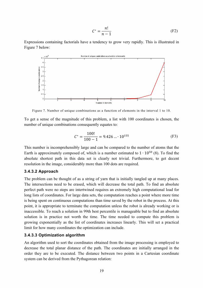
Expressions containing factorials have a tendency to grow very rapidly. This is illustrated in Figure 7 below:
Figure 7. Number of unique combinations as a function of elements in the interval 1 to 10.
To get a sense of the magnitude of this problem, a list with 100 coordinates is chosen, the number of unique combinations consequently equates to:
𝐶∗ =100!
100− 1 = 9.426… ∙ 10!"" (F3)
This number is incomprehensibly large and can be compared to the number of atoms that the Earth is approximately composed of, which is a number estimated to 1 ∙ 10!" (8). To find the absolute shortest path in this data set is clearly not trivial. Furthermore, to get decent resolution in the image, considerably more than 100 dots are required.
3.4.3.2 Approach
The problem can be thought of as a string of yarn that is initially tangled up at many places. The intersections need to be erased, which will decrease the total path. To find an absolute perfect path were no steps are intertwined requires an extremely high computational load for long lists of coordinates. For large data sets, the computation reaches a point where more time is being spent on continuous computations than time saved by the robot in the process. At this point, it is appropriate to terminate the computation unless the robot is already working or is inaccessible. To reach a solution in 99th best percentile is manageable but to find an absolute solution is in practice not worth the time. The time needed to compute this problem is growing exponentially as the list of coordinates increases linearly. This will set a practical limit for how many coordinates the optimization can include.
3.4.3.3 Optimization algorithm
An algorithm used to sort the coordinates obtained from the image processing is employed to decrease the total planar distance of the path. The coordinates are initially arranged in the order they are to be executed. The distance between two points in a Cartesian coordinate system can be derived from the Pythagorean relation:
20
𝑑 = (𝑦! − 𝑦!)! + (𝑥! − 𝑥!)! (G1)
This can be done to determine the distance between all coordinates in the list. The sum of these distances constitutes the total path distance since all moves are linear.
Firstly, the distances between all adjacent points in the order are calculated. Thereafter, distances to other possible points are calculated. If any distance is noted to be shorter, the order of the coordinates is rearranged.
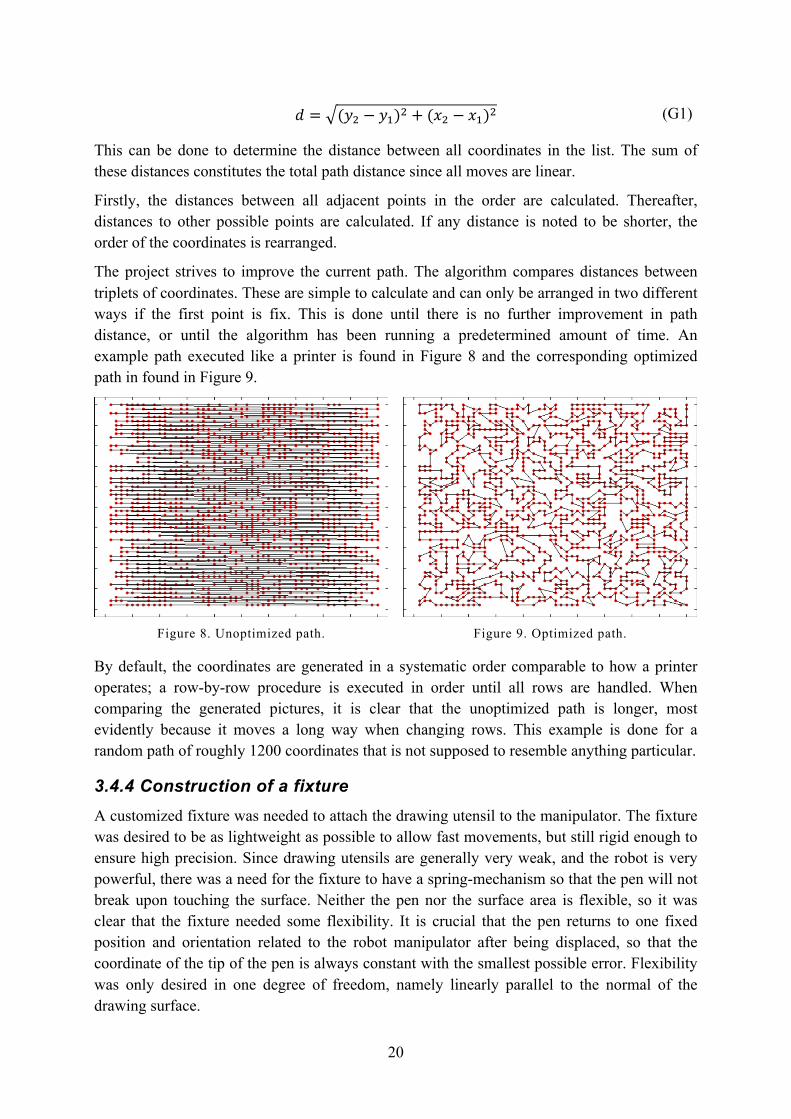
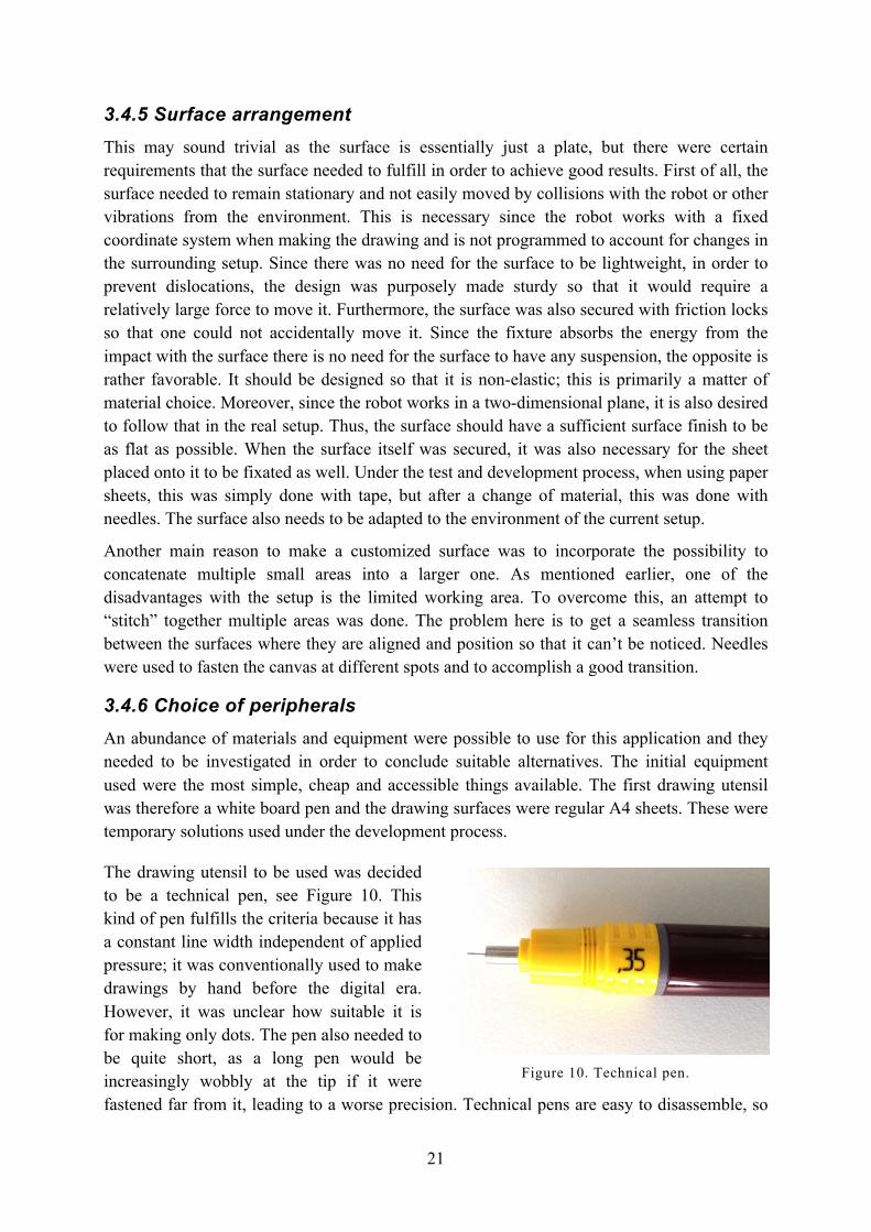
The project strives to improve the current path. The algorithm compares distances between triplets of coordinates. These are simple to calculate and can only be arranged in two different ways if the first point is fix. This is done until there is no further improvement in path distance, or until the algorithm has been running a predetermined amount of time. An example path executed like a printer is found in Figure 8 and the corresponding optimized path in found in Figure 9.
Figure 8. Unoptimized path. Figure 9. Optimized path.
By default, the coordinates are generated in a systematic order comparable to how a printer operates; a row-by-row procedure is executed in order until all rows are handled. When comparing the generated pictures, it is clear that the unoptimized path is longer, most evidently because it moves a long way when changing rows. This example is done for a random path of roughly 1200 coordinates that is not supposed to resemble anything particular.
3.4.4 Construction of a fixture A customized fixture was needed to attach the drawing utensil to the manipulator. The fixture was desired to be as lightweight as possible to allow fast movements, but still rigid enough to ensure high precision. Since drawing utensils are generally very weak, and the robot is very powerful, there was a need for the fixture to have a spring-mechanism so that the pen will not break upon touching the surface. Neither the pen nor the surface area is flexible, so it was clear that the fixture needed some flexibility. It is crucial that the pen returns to one fixed position and orientation related to the robot manipulator after being displaced, so that the coordinate of the tip of the pen is always constant with the smallest possible error. Flexibility was only desired in one degree of freedom, namely linearly parallel to the normal of the drawing surface.
21
3.4.5 Surface arrangement This may sound trivial as the surface is essentially just a plate, but there were certain requirements that the surface needed to fulfill in order to achieve good results. First of all, the surface needed to remain stationary and not easily moved by collisions with the robot or other vibrations from the environment. This is necessary since the robot works with a fixed coordinate system when making the drawing and is not programmed to account for changes in the surrounding setup. Since there was no need for the surface to be lightweight, in order to prevent dislocations, the design was purposely made sturdy so that it would require a relatively large force to move it. Furthermore, the surface was also secured with friction locks so that one could not accidentally move it. Since the fixture absorbs the energy from the impact with the surface there is no need for the surface to have any suspension, the opposite is rather favorable. It should be designed so that it is non-elastic; this is primarily a matter of material choice. Moreover, since the robot works in a two-dimensional plane, it is also desired to follow that in the real setup. Thus, the surface should have a sufficient surface finish to be as flat as possible. When the surface itself was secured, it was also necessary for the sheet placed onto it to be fixated as well. Under the test and development process, when using paper sheets, this was simply done with tape, but after a change of material, this was done with needles. The surface also needs to be adapted to the environment of the current setup.
Another main reason to make a customized surface was to incorporate the possibility to concatenate multiple small areas into a larger one. As mentioned earlier, one of the disadvantages with the setup is the limited working area. To overcome this, an attempt to “stitch” together multiple areas was done. The problem here is to get a seamless transition between the surfaces where they are aligned and position so that it can’t be noticed. Needles were used to fasten the canvas at different spots and to accomplish a good transition.
3.4.6 Choice of peripherals An abundance of materials and equipment were possible to use for this application and they needed to be investigated in order to conclude suitable alternatives. The initial equipment used were the most simple, cheap and accessible things available. The first drawing utensil was therefore a white board pen and the drawing surfaces were regular A4 sheets. These were temporary solutions used under the development process.
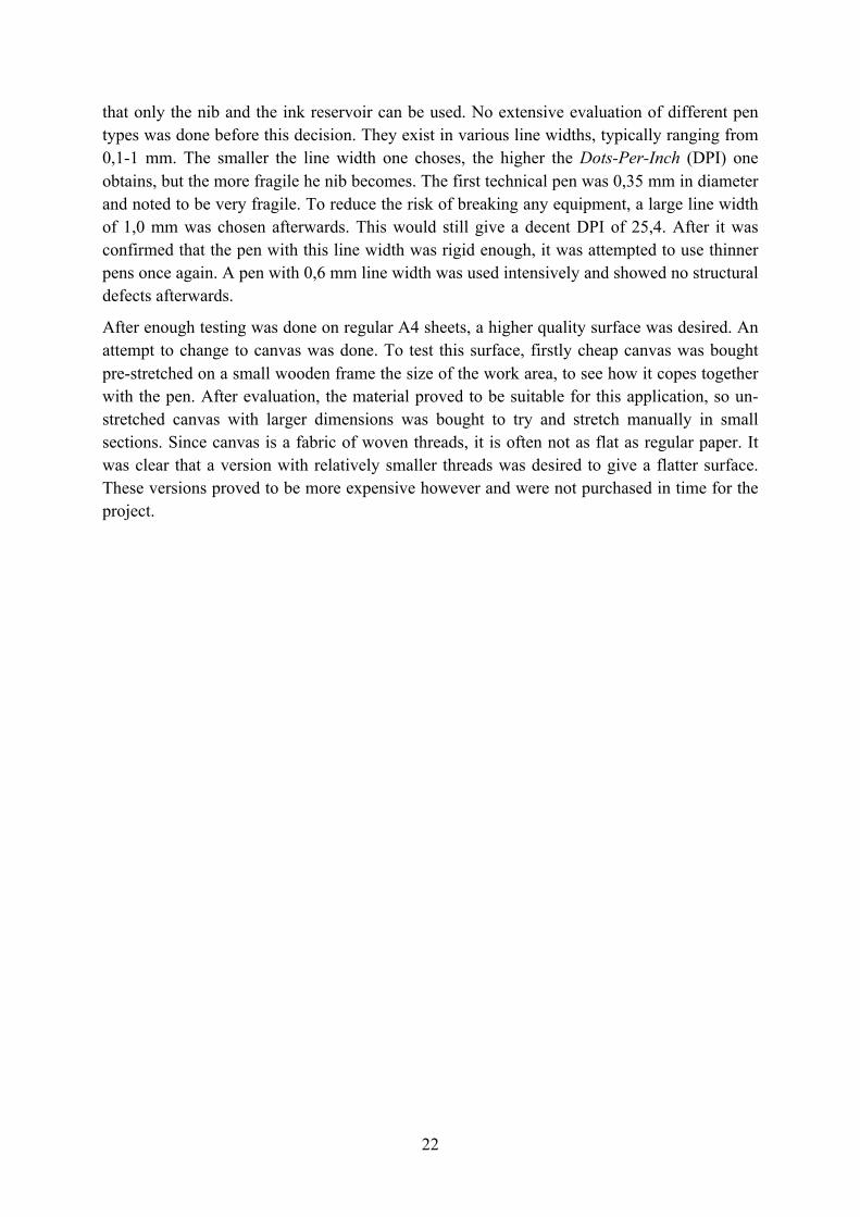
The drawing utensil to be used was decided to be a technical pen, see Figure 10. This kind of pen fulfills the criteria because it has a constant line width independent of applied pressure; it was conventionally used to make drawings by hand before the digital era. However, it was unclear how suitable it is for making only dots. The pen also needed to be quite short, as a long pen would be increasingly wobbly at the tip if it were fastened far from it, leading to a worse precision. Technical pens are easy to disassemble, so
Figure 10. Technical pen.
22
that only the nib and the ink reservoir can be used. No extensive evaluation of different pen types was done before this decision. They exist in various line widths, typically ranging from 0,1-1 mm. The smaller the line width one choses, the higher the Dots-Per-Inch (DPI) one obtains, but the more fragile he nib becomes. The first technical pen was 0,35 mm in diameter and noted to be very fragile. To reduce the risk of breaking any equipment, a large line width of 1,0 mm was chosen afterwards. This would still give a decent DPI of 25,4. After it was confirmed that the pen with this line width was rigid enough, it was attempted to use thinner pens once again. A pen with 0,6 mm line width was used intensively and showed no structural defects afterwards.
After enough testing was done on regular A4 sheets, a higher quality surface was desired. An attempt to change to canvas was done. To test this surface, firstly cheap canvas was bought pre-stretched on a small wooden frame the size of the work area, to see how it copes together with the pen. After evaluation, the material proved to be suitable for this application, so un-stretched canvas with larger dimensions was bought to try and stretch manually in small sections. Since canvas is a fabric of woven threads, it is often not as flat as regular paper. It was clear that a version with relatively smaller threads was desired to give a flatter surface. These versions proved to be more expensive however and were not purchased in time for the project.
23
4 RESULTS The results obtained from all features of the project are compiled under this chapter.
4.1 The fixture The need for a customized fixture and its requirements were discovered in practice. Initially, a pen was mounted to the robot, but its nib was instantly broken because it could not absorb the energy of the impact. Furthermore, the pens are quite special and expensive, so to continue breaking such equipment was not an option. This led to the realization that the structure needs to be deformable but able to regain its initial geometry.
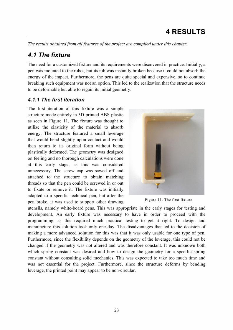
4.1.1 The first iteration The first iteration of this fixture was a simple structure made entirely in 3D-printed ABS-plastic as seen in Figure 11. The fixture was thought to utilize the elasticity of the material to absorb energy. The structure featured a small leverage that would bend slightly upon contact and would then return to its original form without being plastically deformed. The geometry was designed on feeling and no thorough calculations were done at this early stage, as this was considered unnecessary. The screw cap was sawed off and attached to the structure to obtain matching threads so that the pen could be screwed in or out to fixate or remove it. The fixture was initially adapted to a specific technical pen, but after the pen broke, it was used to support other drawing utensils, namely white-board pens. This was appropriate in the early stages for testing and development. An early fixture was necessary to have in order to proceed with the programming, as this required much practical testing to get it right. To design and manufacture this solution took only one day. The disadvantages that led to the decision of making a more advanced solution for this was that it was only usable for one type of pen. Furthermore, since the flexibility depends on the geometry of the leverage, this could not be changed if the geometry was not altered and was therefore constant. It was unknown both which spring constant was desired and how to design the geometry for a specific spring constant without consulting solid mechanics. This was expected to take too much time and was not essential for the project. Furthermore, since the structure deforms by bending leverage, the printed point may appear to be non-circular.
Figure 11. The first fixture.
24
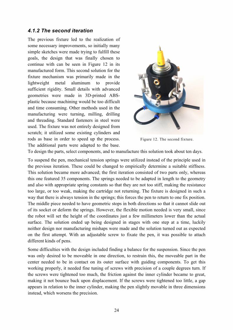
4.1.2 The second iteration The previous fixture led to the realization of some necessary improvements, so initially many simple sketches were made trying to fulfill these goals, the design that was finally chosen to continue with can be seen in Figure 12 in its manufactured form. This second solution for the fixture mechanism was primarily made in the lightweight metal aluminum to provide sufficient rigidity. Small details with advanced geometries were made in 3D-printed ABS-plastic because machining would be too difficult and time consuming. Other methods used in the manufacturing were turning, milling, drilling and threading. Standard fasteners in steel were used. The fixture was not entirely designed from scratch; it utilized some existing cylinders and rods as base in order to speed up the process. The additional parts were adapted to the base. To design the parts, select components, and to manufacture this solution took about ten days.
To suspend the pen, mechanical tension springs were utilized instead of the principle used in the previous iteration. These could be changed to empirically determine a suitable stiffness. This solution became more advanced; the first iteration consisted of two parts only, whereas this one featured 35 components. The springs needed to be adapted in length to the geometry and also with appropriate spring constants so that they are not too stiff, making the resistance too large, or too weak, making the cartridge not returning. The fixture is designed in such a way that there is always tension in the springs; this forces the pen to return to one fix position. The middle piece needed to have geometric stops in both directions so that it cannot slide out of its socket or deform the springs. However, the flexible motion needed is very small, since the robot will set the height of the coordinates just a few millimeters lower than the actual surface. The solution ended up being designed in stages with one step at a time, luckily neither design nor manufacturing mishaps were made and the solution turned out as expected on the first attempt. With an adjustable screw to fixate the pen, it was possible to attach different kinds of pens.
Some difficulties with the design included finding a balance for the suspension. Since the pen was only desired to be moveable in one direction, to restrain this, the moveable part in the center needed to be in contact on its outer surface with guiding components. To get this working properly, it needed fine tuning of screws with precision of a couple degrees turn. If the screws were tightened too much, the friction against the inner cylinder became to great, making it not bounce back upon displacement. If the screws were tightened too little, a gap appears in relation to the inner cylinder, making the pen slightly movable in three dimensions instead, which worsens the precision.
Figure 12. The second fixture.
25
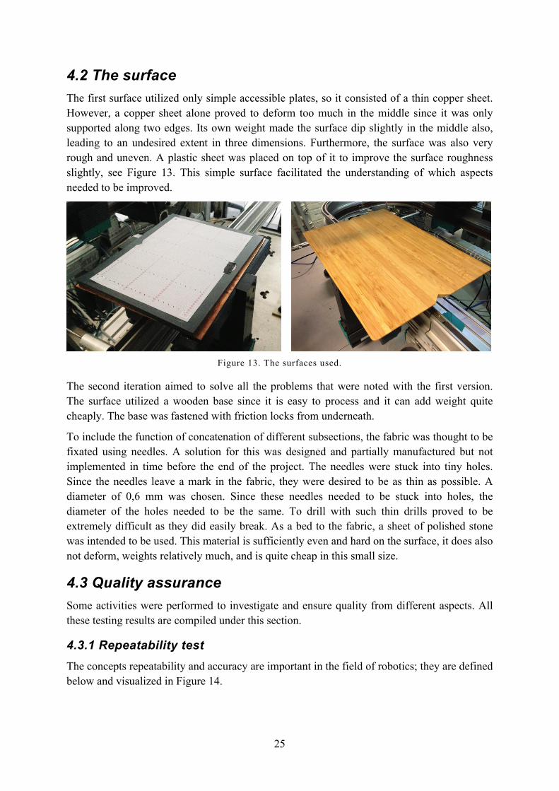
4.2 The surface The first surface utilized only simple accessible plates, so it consisted of a thin copper sheet. However, a copper sheet alone proved to deform too much in the middle since it was only supported along two edges. Its own weight made the surface dip slightly in the middle also, leading to an undesired extent in three dimensions. Furthermore, the surface was also very rough and uneven. A plastic sheet was placed on top of it to improve the surface roughness slightly, see Figure 13. This simple surface facilitated the understanding of which aspects needed to be improved.
Figure 13. The surfaces used.
The second iteration aimed to solve all the problems that were noted with the first version. The surface utilized a wooden base since it is easy to process and it can add weight quite cheaply. The base was fastened with friction locks from underneath.
To include the function of concatenation of different subsections, the fabric was thought to be fixated using needles. A solution for this was designed and partially manufactured but not implemented in time before the end of the project. The needles were stuck into tiny holes. Since the needles leave a mark in the fabric, they were desired to be as thin as possible. A diameter of 0,6 mm was chosen. Since these needles needed to be stuck into holes, the diameter of the holes needed to be the same. To drill with such thin drills proved to be extremely difficult as they did easily break. As a bed to the fabric, a sheet of polished stone was intended to be used. This material is sufficiently even and hard on the surface, it does also not deform, weights relatively much, and is quite cheap in this small size.
4.3 Quality assurance Some activities were performed to investigate and ensure quality from different aspects. All these testing results are compiled under this section.
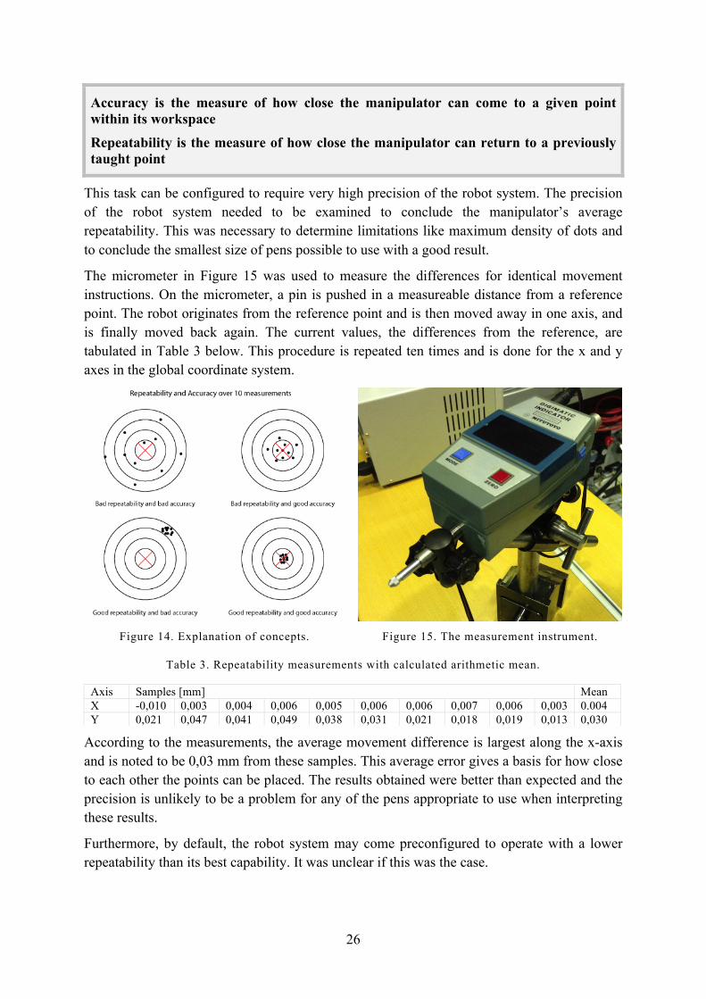
4.3.1 Repeatability test The concepts repeatability and accuracy are important in the field of robotics; they are defined below and visualized in Figure 14.
26
Accuracy is the measure of how close the manipulator can come to a given point within its workspace
Repeatability is the measure of how close the manipulator can return to a previously taught point
This task can be configured to require very high precision of the robot system. The precision of the robot system needed to be examined to conclude the manipulator’s average repeatability. This was necessary to determine limitations like maximum density of dots and to conclude the smallest size of pens possible to use with a good result.
The micrometer in Figure 15 was used to measure the differences for identical movement instructions. On the micrometer, a pin is pushed in a measureable distance from a reference point. The robot originates from the reference point and is then moved away in one axis, and is finally moved back again. The current values, the differences from the reference, are tabulated in Table 3 below. This procedure is repeated ten times and is done for the x and y axes in the global coordinate system.
Figure 14. Explanation of concepts. Figure 15. The measurement instrument.
Table 3. Repeatability measurements with calculated arithmetic mean.
According to the measurements, the average movement difference is largest along the x-axis and is noted to be 0,03 mm from these samples. This average error gives a basis for how close to each other the points can be placed. The results obtained were better than expected and the precision is unlikely to be a problem for any of the pens appropriate to use when interpreting these results.
Furthermore, by default, the robot system may come preconfigured to operate with a lower repeatability than its best capability. It was unclear if this was the case.
Axis Samples [mm] Mean X -0,010 0,003 0,004 0,006 0,005 0,006 0,006 0,007 0,006 0,003 0.004 Y 0,021 0,047 0,041 0,049 0,038 0,031 0,021 0,018 0,019 0,013 0,030
27
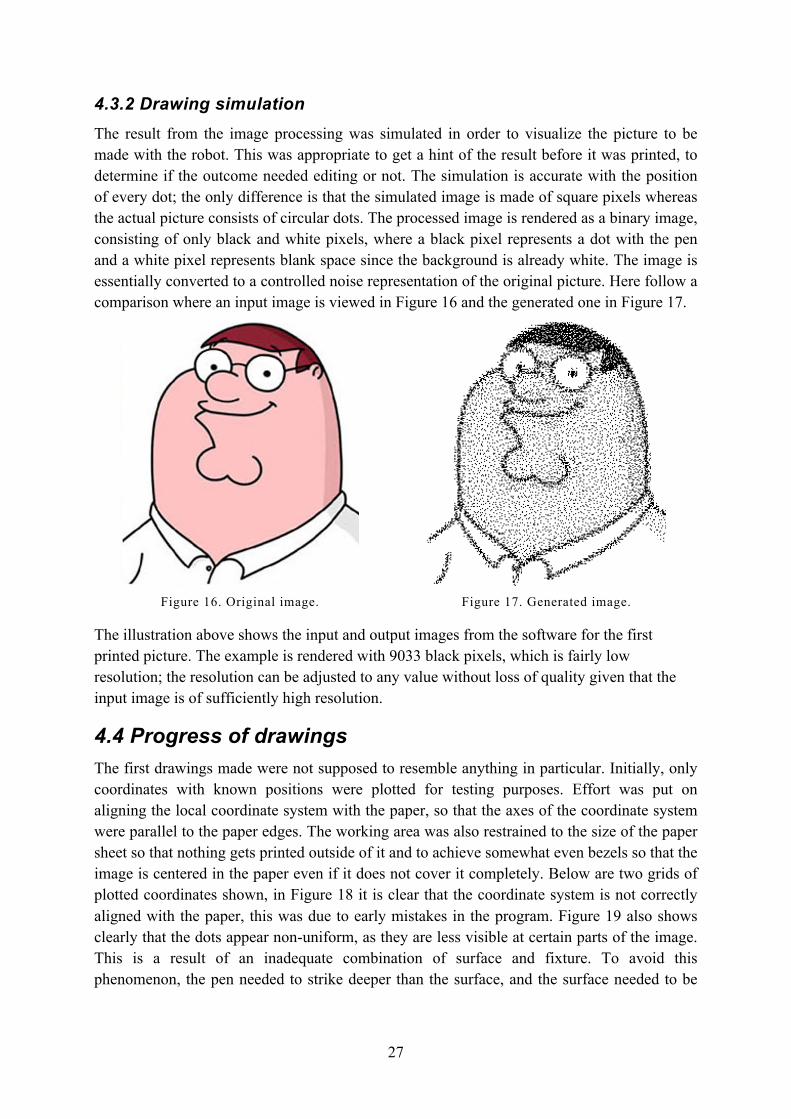
4.3.2 Drawing simulation The result from the image processing was simulated in order to visualize the picture to be made with the robot. This was appropriate to get a hint of the result before it was printed, to determine if the outcome needed editing or not. The simulation is accurate with the position of every dot; the only difference is that the simulated image is made of square pixels whereas the actual picture consists of circular dots. The processed image is rendered as a binary image, consisting of only black and white pixels, where a black pixel represents a dot with the pen and a white pixel represents blank space since the background is already white. The image is essentially converted to a controlled noise representation of the original picture. Here follow a comparison where an input image is viewed in Figure 16 and the generated one in Figure 17.
Figure 16. Original image. Figure 17. Generated image.
The illustration above shows the input and output images from the software for the first printed picture. The example is rendered with 9033 black pixels, which is fairly low resolution; the resolution can be adjusted to any value without loss of quality given that the input image is of sufficiently high resolution.
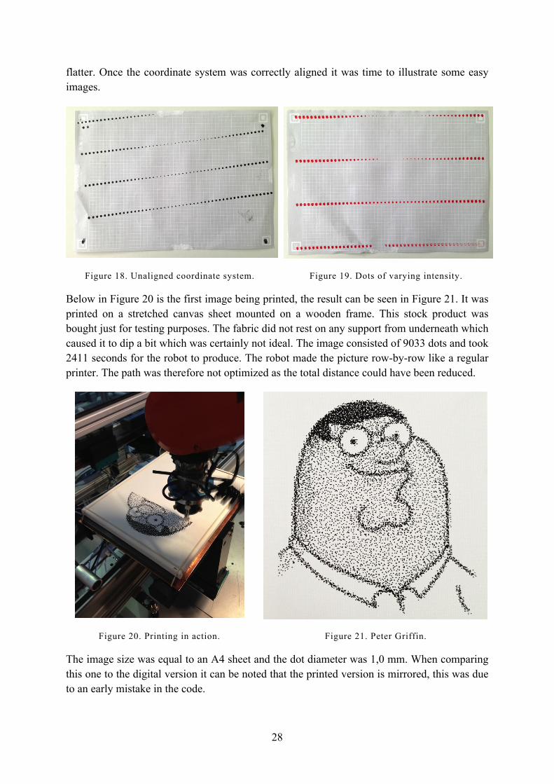
4.4 Progress of drawings The first drawings made were not supposed to resemble anything in particular. Initially, only coordinates with known positions were plotted for testing purposes. Effort was put on aligning the local coordinate system with the paper, so that the axes of the coordinate system were parallel to the paper edges. The working area was also restrained to the size of the paper sheet so that nothing gets printed outside of it and to achieve somewhat even bezels so that the image is centered in the paper even if it does not cover it completely. Below are two grids of plotted coordinates shown, in Figure 18 it is clear that the coordinate system is not correctly aligned with the paper, this was due to early mistakes in the program. Figure 19 also shows clearly that the dots appear non-uniform, as they are less visible at certain parts of the image. This is a result of an inadequate combination of surface and fixture. To avoid this phenomenon, the pen needed to strike deeper than the surface, and the surface needed to be
28
flatter. Once the coordinate system was correctly aligned it was time to illustrate some easy images.
Figure 18. Unaligned coordinate system. Figure 19. Dots of varying intensity.
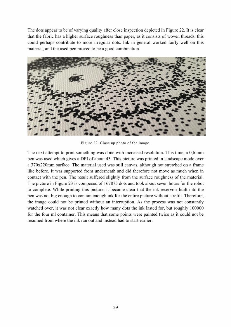
Below in Figure 20 is the first image being printed, the result can be seen in Figure 21. It was printed on a stretched canvas sheet mounted on a wooden frame. This stock product was bought just for testing purposes. The fabric did not rest on any support from underneath which caused it to dip a bit which was certainly not ideal. The image consisted of 9033 dots and took 2411 seconds for the robot to produce. The robot made the picture row-by-row like a regular printer. The path was therefore not optimized as the total distance could have been reduced.
Figure 20. Printing in action. Figure 21. Peter Griffin.
The image size was equal to an A4 sheet and the dot diameter was 1,0 mm. When comparing this one to the digital version it can be noted that the printed version is mirrored, this was due to an early mistake in the code.
29
The dots appear to be of varying quality after close inspection depicted in Figure 22. It is clear that the fabric has a higher surface roughness than paper, as it consists of woven threads, this could perhaps contribute to more irregular dots. Ink in general worked fairly well on this material, and the used pen proved to be a good combination.
Figure 22. Close up photo of the image.
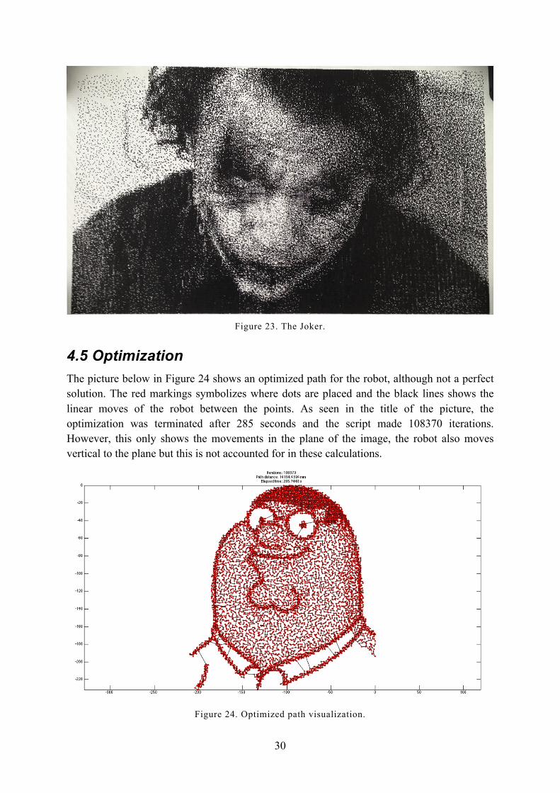
The next attempt to print something was done with increased resolution. This time, a 0,6 mm pen was used which gives a DPI of about 43. This picture was printed in landscape mode over a 370x220mm surface. The material used was still canvas, although not stretched on a frame like before. It was supported from underneath and did therefore not move as much when in contact with the pen. The result suffered slightly from the surface roughness of the material. The picture in Figure 23 is composed of 167875 dots and took about seven hours for the robot to complete. While printing this picture, it became clear that the ink reservoir built into the pen was not big enough to contain enough ink for the entire picture without a refill. Therefore, the image could not be printed without an interruption. As the process was not constantly watched over, it was not clear exactly how many dots the ink lasted for, but roughly 100000 for the four ml container. This means that some points were painted twice as it could not be resumed from where the ink ran out and instead had to start earlier.
30
Figure 23. The Joker.
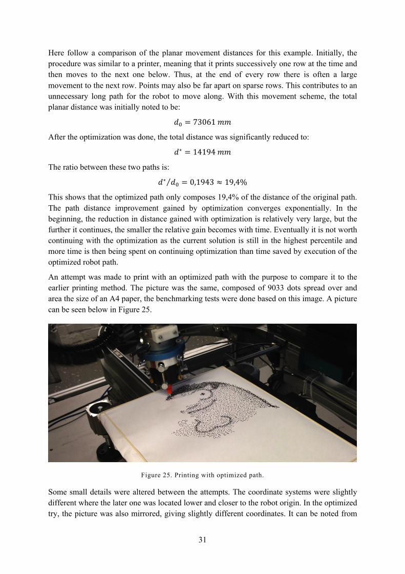
4.5 Optimization The picture below in Figure 24 shows an optimized path for the robot, although not a perfect solution. The red markings symbolizes where dots are placed and the black lines shows the linear moves of the robot between the points. As seen in the title of the picture, the optimization was terminated after 285 seconds and the script made 108370 iterations. However, this only shows the movements in the plane of the image, the robot also moves vertical to the plane but this is not accounted for in these calculations.
Figure 24. Optimized path visualization.
31
Here follow a comparison of the planar movement distances for this example. Initially, the procedure was similar to a printer, meaning that it prints successively one row at the time and then moves to the next one below. Thus, at the end of every row there is often a large movement to the next row. Points may also be far apart on sparse rows. This contributes to an unnecessary long path for the robot to move along. With this movement scheme, the total planar distance was initially noted to be:
𝑑! = 73061 𝑚𝑚
After the optimization was done, the total distance was significantly reduced to:
𝑑∗ = 14194 𝑚𝑚
The ratio between these two paths is:
𝑑∗ 𝑑! = 0,1943 ≈ 19,4%
This shows that the optimized path only composes 19,4% of the distance of the original path. The path distance improvement gained by optimization converges exponentially. In the beginning, the reduction in distance gained with optimization is relatively very large, but the further it continues, the smaller the relative gain becomes with time. Eventually it is not worth continuing with the optimization as the current solution is still in the highest percentile and more time is then being spent on continuing optimization than time saved by execution of the optimized robot path.
An attempt was made to print with an optimized path with the purpose to compare it to the earlier printing method. The picture was the same, composed of 9033 dots spread over and area the size of an A4 paper, the benchmarking tests were done based on this image. A picture can be seen below in Figure 25.
Figure 25. Printing with optimized path.
Some small details were altered between the attempts. The coordinate systems were slightly different where the later one was located lower and closer to the robot origin. In the optimized try, the picture was also mirrored, giving slightly different coordinates. It can be noted from
32
the picture that the robot prints the dots in an unpredictable way. The time to print the optimized version was recorded to be 2392 seconds, only 18 seconds faster than the original version. Since it took almost six minutes to do the calculations for the optimization, this proved to be unnecessary in practice. This minor improvement caused much confusion at the time and could be traced to the relatively high distance of 20 mm that the robot rises over the surface between each point. This was further investigated and it was decided to do a more thorough performance benchmark.
4.6 Performance benchmark To assess the performance of the setup was considered necessary to get at hint of the total processing time for large jobs, with this data it could be possible to predict and model how long time a program would need in order to finish. A counter was included in the robot program that prints the run time after the process is fully executed.
When the average cycle time is known, it is possible to take the total number of dots for a picture and multiply this with the cycle time to get an estimation of the run time. This would give an estimated time for how long it would take to finish a job.
The robot was observed to move slower between coordinates far away from its origin, so it is clear that the relative cycle time is not constant independently of the position in the coordinate system.
The performance of the image processing scripts is very fast as it only takes a couple of seconds depending on the image resolution. The same holds true for the generation of the robot code. The only computationally heavy execution is the optimization when it comes to software.
The regular path is already far from the worst possible path since it is already arranged in a very systematic way. The optimization script can be inverted to conclude it the largest possible path, and it would be many times larger than the regular one.
The relative height over the surface that the robot rises to, used for the first testing of the optimized path, was 20 mm. One explanation to the minor improvement previously obtained may be that, given that the three-dimensional distance is almost the same for the robot to move, it does not matter if the horizontal distance is slightly longer since the vertical is already much longer than the average horizontal distance between two points. By this logic, it was concluded that the optimization might have a larger impact if the relative height is reduced. To investigate this closer, new experiments were made with different heights. The results are tabulated in Table 4 below:
33
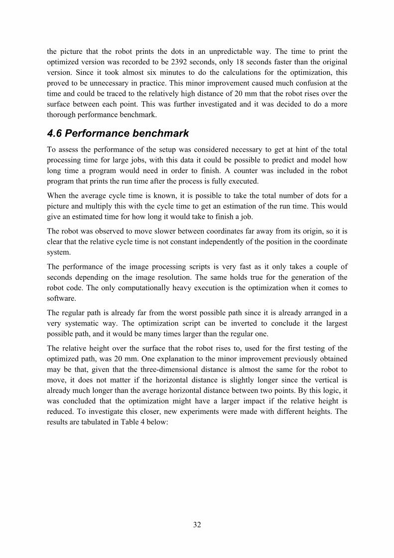
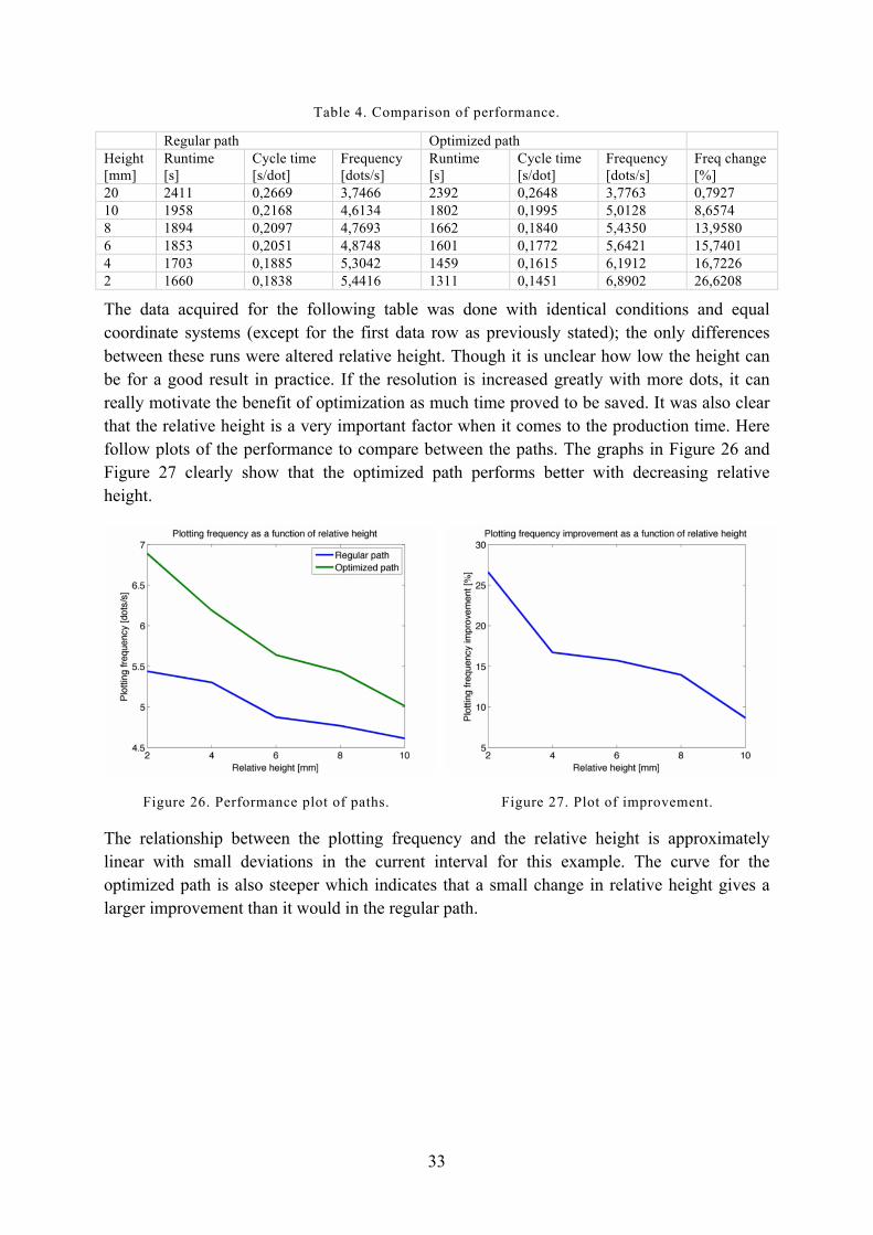
Table 4. Comparison of performance.
Regular path Optimized path Height [mm]
Runtime [s]
Cycle time [s/dot]
Frequency [dots/s]
Runtime [s]
Cycle time [s/dot]
Frequency [dots/s]
Freq change [%]
20 2411 0,2669 3,7466 2392 0,2648 3,7763 0,7927 10 1958 0,2168 4,6134 1802 0,1995 5,0128 8,6574 8 1894 0,2097 4,7693 1662 0,1840 5,4350 13,9580 6 1853 0,2051 4,8748 1601 0,1772 5,6421 15,7401 4 1703 0,1885 5,3042 1459 0,1615 6,1912 16,7226 2 1660 0,1838 5,4416 1311 0,1451 6,8902 26,6208
The data acquired for the following table was done with identical conditions and equal coordinate systems (except for the first data row as previously stated); the only differences between these runs were altered relative height. Though it is unclear how low the height can be for a good result in practice. If the resolution is increased greatly with more dots, it can really motivate the benefit of optimization as much time proved to be saved. It was also clear that the relative height is a very important factor when it comes to the production time. Here follow plots of the performance to compare between the paths. The graphs in Figure 26 and Figure 27 clearly show that the optimized path performs better with decreasing relative height.
Figure 26. Performance plot of paths. Figure 27. Plot of improvement.
The relationship between the plotting frequency and the relative height is approximately linear with small deviations in the current interval for this example. The curve for the optimized path is also steeper which indicates that a small change in relative height gives a larger improvement than it would in the regular path.

34
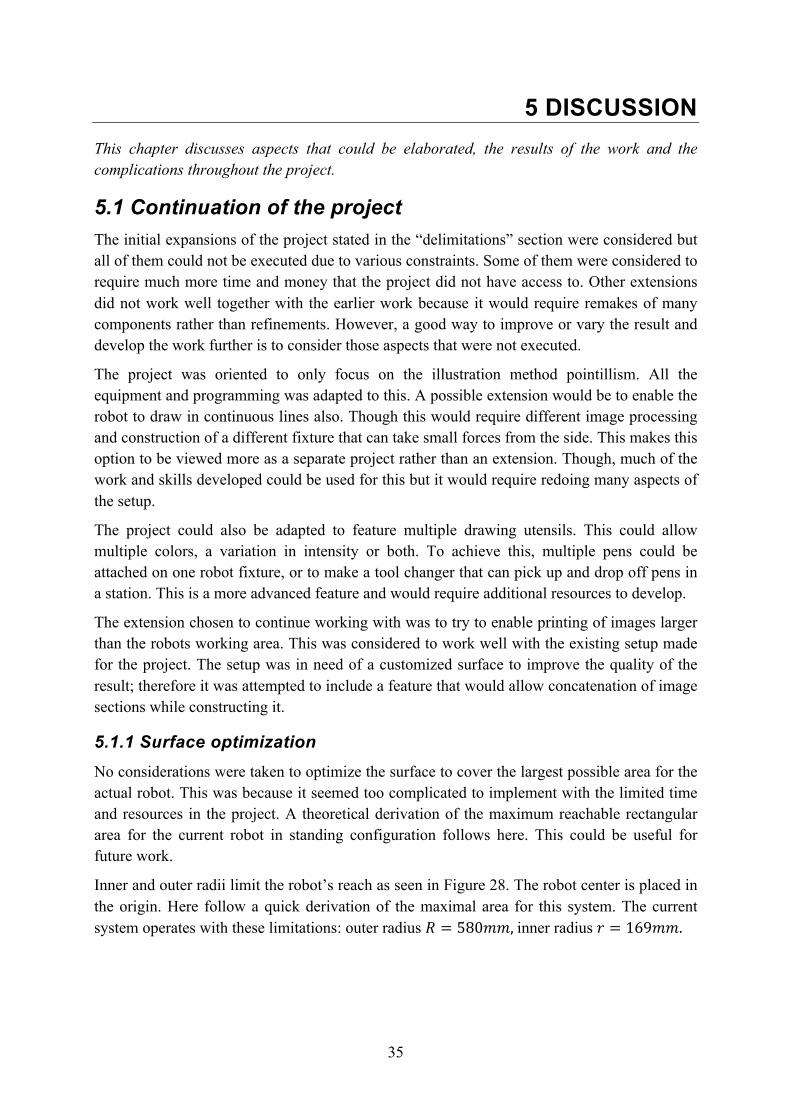
35
5 DISCUSSION This chapter discusses aspects that could be elaborated, the results of the work and the complications throughout the project.
5.1 Continuation of the project The initial expansions of the project stated in the “delimitations” section were considered but all of them could not be executed due to various constraints. Some of them were considered to require much more time and money that the project did not have access to. Other extensions did not work well together with the earlier work because it would require remakes of many components rather than refinements. However, a good way to improve or vary the result and develop the work further is to consider those aspects that were not executed.
The project was oriented to only focus on the illustration method pointillism. All the equipment and programming was adapted to this. A possible extension would be to enable the robot to draw in continuous lines also. Though this would require different image processing and construction of a different fixture that can take small forces from the side. This makes this option to be viewed more as a separate project rather than an extension. Though, much of the work and skills developed could be used for this but it would require redoing many aspects of the setup.
The project could also be adapted to feature multiple drawing utensils. This could allow multiple colors, a variation in intensity or both. To achieve this, multiple pens could be attached on one robot fixture, or to make a tool changer that can pick up and drop off pens in a station. This is a more advanced feature and would require additional resources to develop.
The extension chosen to continue working with was to try to enable printing of images larger than the robots working area. This was considered to work well with the existing setup made for the project. The setup was in need of a customized surface to improve the quality of the result; therefore it was attempted to include a feature that would allow concatenation of image sections while constructing it.
5.1.1 Surface optimization No considerations were taken to optimize the surface to cover the largest possible area for the actual robot. This was because it seemed too complicated to implement with the limited time and resources in the project. A theoretical derivation of the maximum reachable rectangular area for the current robot in standing configuration follows here. This could be useful for future work.
Inner and outer radii limit the robot’s reach as seen in Figure 28. The robot center is placed in the origin. Here follow a quick derivation of the maximal area for this system. The current system operates with these limitations: outer radius 𝑅 = 580𝑚𝑚, inner radius 𝑟 = 169𝑚𝑚.
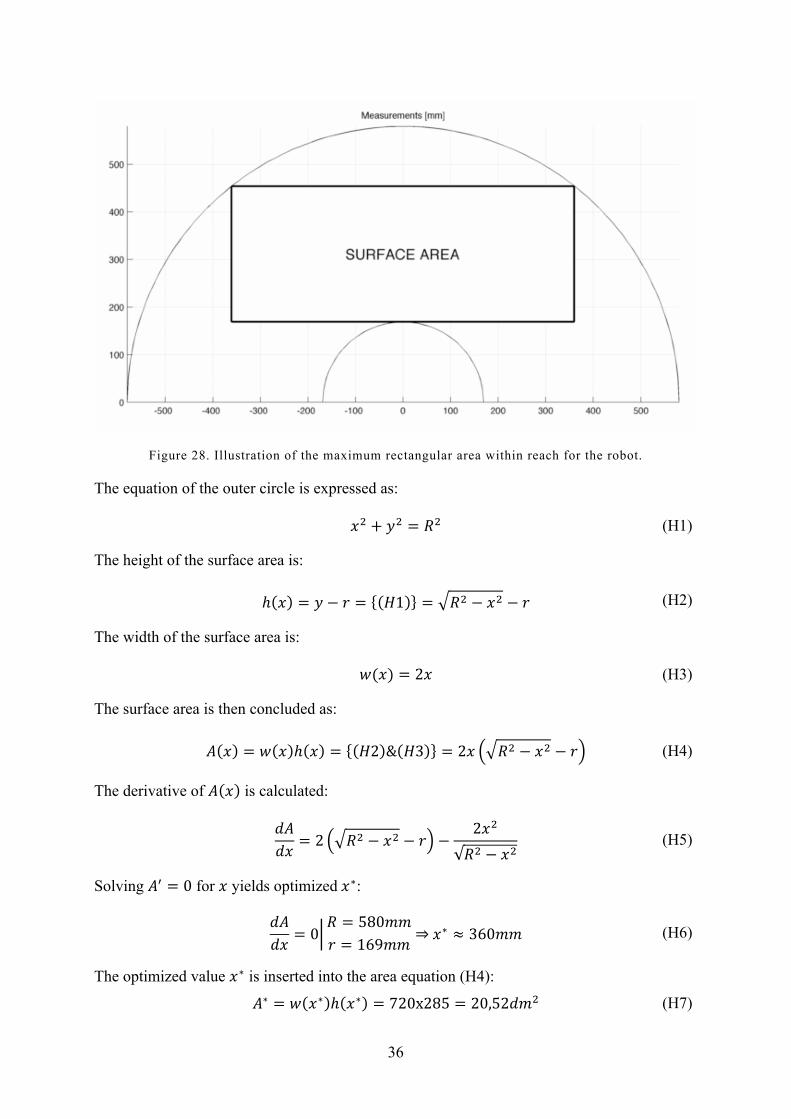
36
Figure 28. Illustration of the maximum rectangular area within reach for the robot.
The equation of the outer circle is expressed as:
𝑥! + 𝑦! = 𝑅! (H1)
The height of the surface area is:
ℎ 𝑥 = 𝑦 − 𝑟 = 𝐻1 = 𝑅! − 𝑥! − 𝑟 (H2)
The width of the surface area is:
𝑤(𝑥) = 2𝑥 (H3)
The surface area is then concluded as:
𝐴 𝑥 = 𝑤 𝑥 ℎ 𝑥 = 𝐻2 & 𝐻3 = 2𝑥 𝑅! − 𝑥! − 𝑟 (H4)
The derivative of 𝐴 𝑥 is calculated:
𝑑𝐴𝑑𝑥 = 2 𝑅! − 𝑥! − 𝑟 −
2𝑥!
𝑅! − 𝑥! (H5)
Solving 𝐴! = 0 for 𝑥 yields optimized 𝑥∗:
𝑑𝐴𝑑𝑥 = 0
𝑅 = 580𝑚𝑚𝑟 = 169𝑚𝑚 𝑥∗ ≈ 360𝑚𝑚 (H6)
The optimized value 𝑥∗ is inserted into the area equation (H4):
𝐴∗ = 𝑤 𝑥∗ ℎ 𝑥∗ = 720x285 = 20,52𝑑𝑚! (H7)
37
Compared to the measurements in the current setup:
𝐴 = 𝑤 x ℎ x = 370x220 = 8,14𝑑𝑚! (H8)
Hence, it is clear that improvements can be done to cover a larger surface area with the robot and thereby make a larger picture.
5.2 Planning It was not evident if a planning was needed for the project or not. As long as the goal was clear and the road to it was understood, the work could always proceed. Not knowing the time required to perform certain tasks made it harder to establish an accurate planning. Not knowing in advance all the tasks required to fulfill a specific goal would make the planning incomplete. Therefore, little effort was put on planning. The project featured many different activities that did not need to be executed in any particular order. Therefore it sometime happened that work was done according to the mood of the respondent. There were many corners where work could be done simultaneously, and a schedule with planned activities was seldom followed. Since one person carried out the project there was no need for cross communication either, which can be viewed as one goal with a planning. Though planning may be crucial in larger projects, it was not clear here. Time that would have been spent on planning was instead spent on working. No time needed to be wasted on decision making which usually takes a lot of time in larger projects.
However, aside from the time aspect, it would have helped to have all tasks predefined before they were executed. It was hard identify all needed tasks in order to accomplish the goal. One experience was that when a set of tasks was completed, it was sometimes not evident how to continue. This led to small halts in the execution when the project needed to be thought through in order to figure out how to proceed and identify new tasks. But since it was hard to conclude all activities since the project was not built on routine, it could not be planned in detail without guessing.
5.3 Results The performance of the system showed that even large pictures could be realized in a considerable amount of time. This was part of the investigation to determine if this was possible. The robot does not require any control during the program execution more than between changes of pictures or after a certain amount of coordinates have been processed. This enables the robot to work independently and for the operator to basically just push play and wait until the work is finished. Though, no interference could be noted without surveillance. The performance was higher than expected from the beginning; much was also gained from optimization.
Since the project deals with very fine details it was required to have a very high precision of the robot in order to achieve a good result. The repeatability of the robot for this application was uncertain before the project was executed but it proved to be sufficient after rigorous testing was done.
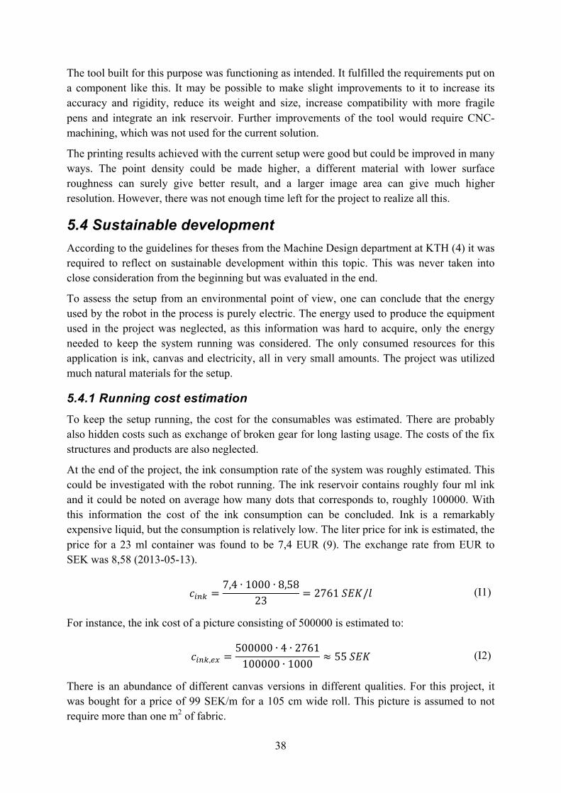
38
The tool built for this purpose was functioning as intended. It fulfilled the requirements put on a component like this. It may be possible to make slight improvements to it to increase its accuracy and rigidity, reduce its weight and size, increase compatibility with more fragile pens and integrate an ink reservoir. Further improvements of the tool would require CNC-machining, which was not used for the current solution.
The printing results achieved with the current setup were good but could be improved in many ways. The point density could be made higher, a different material with lower surface roughness can surely give better result, and a larger image area can give much higher resolution. However, there was not enough time left for the project to realize all this.
5.4 Sustainable development According to the guidelines for theses from the Machine Design department at KTH (4) it was required to reflect on sustainable development within this topic. This was never taken into close consideration from the beginning but was evaluated in the end.
To assess the setup from an environmental point of view, one can conclude that the energy used by the robot in the process is purely electric. The energy used to produce the equipment used in the project was neglected, as this information was hard to acquire, only the energy needed to keep the system running was considered. The only consumed resources for this application is ink, canvas and electricity, all in very small amounts. The project was utilized much natural materials for the setup.
5.4.1 Running cost estimation To keep the setup running, the cost for the consumables was estimated. There are probably also hidden costs such as exchange of broken gear for long lasting usage. The costs of the fix structures and products are also neglected.
At the end of the project, the ink consumption rate of the system was roughly estimated. This could be investigated with the robot running. The ink reservoir contains roughly four ml ink and it could be noted on average how many dots that corresponds to, roughly 100000. With this information the cost of the ink consumption can be concluded. Ink is a remarkably expensive liquid, but the consumption is relatively low. The liter price for ink is estimated, the price for a 23 ml container was found to be 7,4 EUR (9). The exchange rate from EUR to SEK was 8,58 (2013-05-13).
𝑐!"# =7,4 ∙ 1000 ∙ 8,58
23 = 2761 𝑆𝐸𝐾/𝑙 (I1)
For instance, the ink cost of a picture consisting of 500000 is estimated to:
𝑐!"#,!" =500000 ∙ 4 ∙ 2761100000 ∙ 1000 ≈ 55 𝑆𝐸𝐾 (I2)
There is an abundance of different canvas versions in different qualities. For this project, it was bought for a price of 99 SEK/m for a 105 cm wide roll. This picture is assumed to not require more than one m2 of fabric.
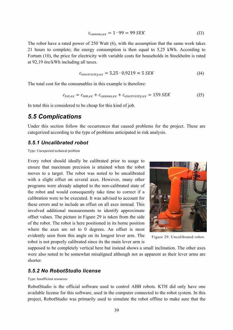
39
𝑐!"#$"%,!" = 1 ∙ 99 = 99 𝑆𝐸𝐾 (I3)
The robot have a rated power of 250 Watt (6), with the assumption that the same work takes 21 hours to complete; the energy consumption is then equal to 5,25 kWh. According to Fortum (10), the price for electricity with variable costs for households in Stockholm is rated at 92,19 öre/kWh including all taxes.
𝑐!"!#$%&#&$',!" = 5,25 ∙ 0,9219 ≈ 5 𝑆𝐸𝐾 (I4)
The total cost for the consumables in this example is therefore:
𝑐!"!,!" = 𝑐!"#,!" + 𝑐!"#$"%,!" + 𝑐!"!#$%&#&$',!" = 159 𝑆𝐸𝐾 (I5)
In total this is considered to be cheap for this kind of job.
5.5 Complications Under this section follow the occurrences that caused problems for the project. These are categorized according to the type of problems anticipated in risk analysis.
5.5.1 Uncalibrated robot Type: Unexpected technical problem
Every robot should ideally be calibrated prior to usage to ensure that maximum precision is attained when the robot moves to a target. The robot was noted to be uncalibrated with a slight offset on several axes. However, many other programs were already adapted to the non-calibrated state of the robot and would consequently take time to correct if a calibration were to be executed. It was advised to account for these errors and to include an offset on all axes instead. This involved additional measurements to identify approximate offset values. The picture in Figure 29 is taken from the side of the robot. The robot is here positioned in its home position where the axes are set to 0 degrees. An offset is most evidently seen from this angle on its longest lever arm. The robot is not properly calibrated since its the main lever arm is supposed to be completely vertical here but instead shows a small inclination. The other axes were also noted to be somewhat misaligned although not as apparent as their lever arms are shorter.
5.5.2 No RobotStudio license Type: Insufficient resources
RobotStudio is the official software used to control ABB robots. KTH did only have one available license for this software, used in the computer connected to the robot system. In this project, RobotStudio was primarily used to simulate the robot offline to make sure that the
Figure 29. Uncalibrated robot.
40
actual program is working as intended without the need to test it on the real system. This proved to be very beneficial when developing a program for the robot. Without this, it became hard to confirm if a program does what it is desired to do. The software offered a 30-day free trial that was used. Afterwards, the computer connected to the robot system was utilized for simulation. Simulation was only critically needed during the development of the main robot program. When it was confirmed to be working, only small changes were made that did not require simulation.
5.5.3 Fragile equipment Type: Other
A fixture was necessary to build in order to attach the drawing utensil to the robot. The fixture needed to be light and flexible, but still rigid enough to make sure that the desired coordinates are reached. The fixture needed to act like a spring mechanism so that the pen does not get damaged. The first tool constructed for the robot was an arrangement made of 3D-printed plastics. The fixture was supposed to utilize the flexibility of the material to absorb energy from the collision. The first pen used on this fixture was a technical pen with a very narrow nib, measuring 0,46 mm on the outer diameter and with a 0,35 mm nozzle hole. This one did not last long as the robot crushed it easily because the fixture was not flexible enough. The nib cannot take large forces from the side; therefore it is very important for the pen to strike the surface perpendicularly, otherwise the pen will end up as seen in Figure 30.
5.5.4 Uneven surface Type: Other
The initial surface used under the drawing was a thin rectangular copper plate slightly larger than an A4 sheet. It rested on a support along two sides, which caused it to bend and dip slightly due to its own weight since there was nothing to support it from underneath. This made the surface extent slightly three-dimensional which was undesired since the robot works in a plane. Furthermore, it was easier to deform in the middle when the robot collided with it. This caused the dots to appear non-uniform. The surface was not completely clean or even either. It was noted that a different surface was needed to achieve a good result. The ideal surface was desired to be totally inflexible and flat. To increase the surface stiffness and reduce the surface roughness, a surface of different material and geometry was adapted to the working area.
5.5.5 Lag Type: Unexpected technical problem
Robot programs are generally adapted for a robot to perform a repetitive cycle in a production line; this does often not require very long programs. However, since this task is not exactly a repeating cycle, it does contain many unique positions. The programs that the robot was fed
Figure 30. Broken pen.
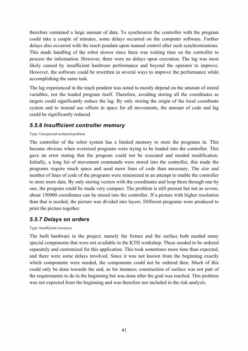
41
therefore contained a large amount of data. To synchronize the controller with the program could take a couple of minutes, some delays occurred on the computer software. Further delays also occurred with the teach pendant upon manual control after such synchronizations. This made handling of the robot slower since there was waiting time on the controller to process the information. However, there were no delays upon execution. The lag was most likely caused by insufficient hardware performance and beyond the operator to improve. However, the software could be rewritten in several ways to improve the performance while accomplishing the same task.
The lag experienced in the teach pendent was noted to mostly depend on the amount of stored variables, not the loaded program itself. Therefore, avoiding storing all the coordinates as targets could significantly reduce the lag. By only storing the origin of the local coordinate system and to instead use offsets in space for all movements, the amount of code and lag could be significantly reduced.
5.5.6 Insufficient controller memory Type: Unexpected technical problem
The controller of the robot system has a limited memory to store the programs in. This became obvious when oversized programs were trying to be loaded into the controller. This gave an error stating that the program could not be executed and needed modification. Initially, a long list of movement commands were stored into the controller, this made the programs require much space and used more lines of code than necessary. The size and number of lines of code of the programs were minimized in an attempt to enable the controller to store more data. By only storing vectors with the coordinates and loop them through one by one, the program could be made very compact. The problem is still present but not as severe, about 150000 coordinates can be stored into the controller. If a picture with higher resolution than that is needed, the picture was divided into layers. Different programs were produced to print the picture together.
5.5.7 Delays on orders Type: Insufficient resources
The built hardware in the project, namely the fixture and the surface both needed many special components that were not available in the KTH workshop. These needed to be ordered separately and customized for this application. This took sometimes more time than expected, and there were some delays involved. Since it was not known from the beginning exactly which components were needed, the components could not be ordered then. Much of this could only be done towards the end, as for instance; construction of surface was not part of the requirements to do in the beginning but was done after the goal was reached. This problem was not expected from the beginning and was therefore not included in the risk analysis.
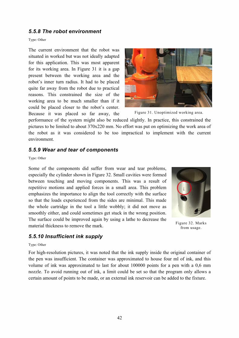
42
5.5.8 The robot environment Type: Other
The current environment that the robot was situated in worked but was not ideally adapted for this application. This was most apparent for its working area. In Figure 31 it is a gap present between the working area and the robot’s inner turn radius. It had to be placed quite far away from the robot due to practical reasons. This constrained the size of the working area to be much smaller than if it could be placed closer to the robot’s center. Because it was placed so far away, the performance of the system might also be reduced slightly. In practice, this constrained the pictures to be limited to about 370x220 mm. No effort was put on optimizing the work area of the robot as it was considered to be too impractical to implement with the current environment.
5.5.9 Wear and tear of components Type: Other
Some of the components did suffer from wear and tear problems, especially the cylinder shown in Figure 32. Small cavities were formed between touching and moving components. This was a result of repetitive motions and applied forces in a small area. This problem emphasizes the importance to align the tool correctly with the surface so that the loads experienced from the sides are minimal. This made the whole cartridge in the tool a little wobbly; it did not move as smoothly either, and could sometimes get stuck in the wrong position. The surface could be improved again by using a lathe to decrease the material thickness to remove the mark.
5.5.10 Insufficient ink supply Type: Other
For high-resolution pictures, it was noted that the ink supply inside the original container of the pen was insufficient. The container was approximated to house four ml of ink, and this volume of ink was approximated to last for about 100000 points for a pen with a 0,6 mm nozzle. To avoid running out of ink, a limit could be set so that the program only allows a certain amount of points to be made, or an external ink reservoir can be added to the fixture.
Figure 31. Unoptimized working area.
Figure 32. Marks from usage.
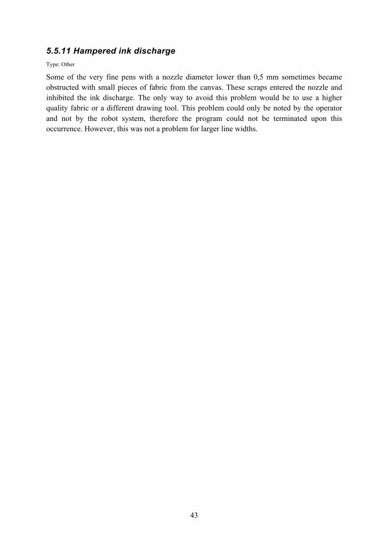
43
5.5.11 Hampered ink discharge Type: Other
Some of the very fine pens with a nozzle diameter lower than 0,5 mm sometimes became obstructed with small pieces of fabric from the canvas. These scraps entered the nozzle and inhibited the ink discharge. The only way to avoid this problem would be to use a higher quality fabric or a different drawing tool. This problem could only be noted by the operator and not by the robot system, therefore the program could not be terminated upon this occurrence. However, this was not a problem for larger line widths.

44
45
6 CONCLUSIONS The overall conclusions of the project are stated in this chapter.
• The goal of the project was achieved with one particular method in time before the scheduled end. However, the goal was viewed as a minimum requirement for the project. The result at that point had potential for improvements from many aspects, whereof a few key aspects were chosen as extension. It was prioritized to improve the result by making a more advanced fixture for the robot. It was also prioritized to make a suitable surface for the robot working area. This led to the construction of different components in the project.
• Optimization of paths proved to be useful in the current configuration if the robot hovered quite close to the surface when moving in between points. With this condition met, time gained by optimization could exceed time spent on computations. However, to find a totally optimized path for high-resolution images proved to be inefficient from a time perspective.
• The project encountered many problems related to the tasks. Many of whom were solved during the project, some were avoided with temporary solutions, and solutions for the rest were proposed.
• The achieved results can be further improved from many different aspects. Some technical improvements can be made to the current setup; however, many further improvements generally require additional resources.
• The progress of the project ran smoothly without any major halts or any adversities that caused the goal of the project to be unachievable. However, often there were delays for progress to be made in one area (time for delivery of components, availability of supervisors, scheduled courses in the workshop etc.) but it was always possible to continue working in other areas of the project in the meantime.
• Not enough time was left to make a larger picture than the working area. The design of a surface with the feature of concatenation was done as well as manufacturing of some components to it, and also the necessary programming. Delays of orders and time constraints forced this to be excluded from the results.
• The project did not require an extensive background research, which allowed more time to be spent on technical development. However, much time was spent on documentation. The robot system and its programming language RAPID were quite easy and user friendly, since it is quite high level it did not require any advanced previous knowledge to use it. The project did only utilize a small amount of available functions also, which made the programming quite quick.

46
47
REFERENCES (1) ABB Robotics Products. (2011). Technical reference manual – RAPID overview.
Västerås. Document ID: 3HAC16580-1, Revision: J.
(2) ABB Robotics Products. (2012). Operating manual – RobotStudio 5.15. Västerås. Document ID: 3HAC032104-‐001, Revision: J.
(3) ABB Robotics Products. (2011). Operating manual – IRC5 with FlexPendant. Västerås. Document ID: 3HAC16590-1, Revision: P.
(4) KTH School of Industrial Engineering and Management. (2012). Masters Thesis Projects at the Department of Machine Design. Stockholm.
(5) ABB Robotics Products. (2010). Technical reference manual – RAPID Instructions, Functions and Data types. Västerås. Document ID: 3HAC 16581-1, Revision: J.
(6) ABB Robotics Products. (2010). Product manual – IRB120 3/0.6. Västerås. Document ID: 3HAC035728-001, Revision: C.
(7) Holmberg, Kaj. (2010). Optimering. ISBN: 978-91-47-09935-1.
(8) WolframAlpha. Estimated number of atoms in the Earth. Consulted 2013-05-27.
URL: http://www.wolframalpha.com/input/?i=number+of+atoms+on+earth
(9) Rotring. E-shop – Drawing ink for technical pens. Consulted: 2013-05-27.
URL: http://www.rotring.com/en/223-drawing-inks-for-isograph-and-variant-ii-black-23ml-4006856591170.html
(10) Fortum AB. Price Comparison of subscriptions. Consulted 2013-05-27.
URL: http://www.fortum.com/countries/se/privat/el/elpriser-avtal/pages/default.aspx