Embed Size (px)
Citation preview

International Symposium on Ionic Liquids in Honour of Marcelle Gaune-Escard
Carry le Rouet, France, June 27-28, 2003
Titanium Electrowinning
Marco V. Ginatta
GTT s.r.l., Torino, Italy
Abstract The importance of making liquid cathodic product cannot be overstated since all the industrial metals are produced liquid. All the advantages of the aluminum electrolysis can be implemented in the titanium cell, in addition to the specific beneficial characteristics of the titanium system. The electrochemistry of titanium is more complex than that of the other industrial metals and this is why titanium has not yet its commercial electrowinning process. Therefore a new fundamental approach in the electrochemical development work was required. A model of three-dimensional interphase is used for representing the mechanism of the electrolyte-electrode reactions. The ongoing progress of the development work of the high temperature titanium electrowinning process is presented.
Advantages of high temperature electrowinning At above 1’700°C titanium forms a liquid cathode with all the process advantages of aluminum electrolysis, which are: • complete physical separation between the metal produced and the electrolyte, with
no entrapped electrolyte as with solid cathodes, thus no need for product separation steps as vacuum distillation or leaching;
• constant electrode surface area, that permits the maintaining of best steady-state values for the electrochemical process parameters;
• shorter interelectrodic distances, thus lower operating voltages, since there is no need for allowing space for irregular crystal growth;
• easier coalescence of microdrops, metal fog, that are liquid, into the liquid cathode surface with horizontal geometry, as compared with suspended solid metal particles on solid cathode with vertical geometry.
Further, titanium electrolysis has the following specific advantages with respect to aluminum electrolysis: • raw material feeding is easier with liquid TiCl4 with much faster rate of utilization as
vapor, as compared with solid alumina that needs special equipment because of slow rate of dissolution and hard crust formation;
• no cathode material problem for holding the liquid metal produced, since titanium has a higher melting point than the electrolyte (it is the contrary with aluminum);
• a solid metal skull that contains the liquid metal cathode is spontaneously formed upon cooling;
• larger difference in density, at their operating temperatures, between the metal and the electrolyte;
• with TiCl4 feed, insoluble dimensionally stable graphite anodes are used (they have been the dream of aluminum people for many decades) since there is no anode

2
consumption by chlorine evolution, thus no anode manufacturing cost; • the purity of the titanium produced is higher than that of aluminum since TiCl4 feed
is purer than alumina and there is no anode impurity addition.
Multilayer Cathodic Interphase model The electrode/electrolyte system in molten salts is represented on the basis of Ref. 1 depicted in Fig. 1 which more recently has been reported in Ref. 2 depicted in Fig. 2. This is a dynamic model that is meant to represent a live steady state electrochemical reduction process in operation at current densities of industrial interest.
Figure 1: One dimensional arrangement of the electrode/electrolyte interphase. [Ref. 1].
Therefore it is important to reason in terms of three-dimensional interphases with significant thicknesses under conditions very much away from the thermodynamic equilibrium of a two-dimensional interface. As a first characterization of the conditions under which the electrochemical reduction process is occurring we recall that: • at a current density of 1 A/cm2 there is very intense movement of species within the
interphase corresponding to the exchange of several thousands of atomic layers each second;
• with an externally applied DC voltage of 3 V on the electrode/electrolyte system, assuming an interphase thickness of 30’000 nm, we have an electric field strength of 100’000V/m acting on charged species within the interphase;
3
• the interphase is home of the fascinating phenomenon of the exchange current density;
• all the values of the physico-chemical parameters are profoundly changing by going from the electrolyte to the electrode, therefore a significant thickness is required for having realistic gradients;
• in molten salt electrolytes there is no solvent, in the sense of water being the base structure of aqueous solutions; therefore the electrolyte must be entirely designed and the simultaneous presence of different anions gives a more complex electrochemical potential series, in which the relative positions of the elements vary in the wide temperature interval;
• the working metal electrode surface is part of the interphase, and we will see the coincidence of the phase transition temperature of Ti metal (alpha-beta) with the maximum Ti subhalides (Ti2+, Ti3+) stability temperature.
It is encouraging that recently Jentoftsen et al., Ref. 3 have started discussing in terms of a laminar layers model.
Fig. 2: The Multilayer cathodic interphase. [Ref. 2].
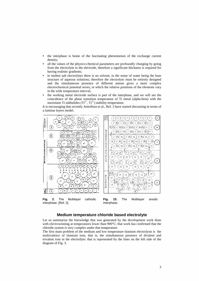
Fig. 15: The Multilayer anodic interphase.
Medium temperature chloride based electrolyte Let us summarize the knowledge that was generated by the development work done with electrowinning at temperatures lower than 900°C; that work has confirmed that the chloride system is very complex under that temperature. The first main problem of the medium and low temperature titanium electrolysis is the multivalence of titanium ions, that is, the simultaneous presence of divalent and trivalent ions in the electrolyte: that is represented by the lines on the left side of the diagram of Fig. 3.

4
Since in general the conditions for electrolysis are better the greater the percentage of divalent titanium in the electrolyte, it is necessary to have the lowest concentration of trivalent titanium ions, that is to keep below 2.1 the average valence of titanium ions in the electrolytes. This condition requires that a separation between anolyte and catholyte be inserted into the cell in order to avoid the alternating oxidation and reduction of titanium ions which results in very low current efficiencies. The main difficulty for fulfilling that requirement is that, at the same time, we have to permit to chlorine ions to transfer between the catholyte, where they enter with TiCl4 feed, to the anolyte, where they are evolved as chlorine gas from the anode. Even considering the various titanium-alkali-chlorine complexes, it has been impossible to device a non-conductive physical diaphragm which would work for periods of time of industrial interest. The operation of intermediate electrodes satisfies the above requirements for a separation selective for titanium ions, but requires the engineering of complicated plants. This situation defies the original reasons that suggested the selection of low temperature electrolytic systems: simpler materials and design problems with respect to high temperature cells. In fact, Fig. 4 depicts a GTT intermediate electrode/anode assembly (called TA in Ref. 4) which is composed of the central graphite anodes with, at each side, an intermediate electrode (called TEB in Ref. 4).
Fig. 3: The standard free energies of formation of titanium chlorides. [Ref.12].
Fig. 4: The GTT intermediate electrode and anode assembly. [Ref. 4].
The TEB maintains the separation between anolyte and catholyte, by using the "distal panel" deposition-dissolution mechanism. Fig. 5 depicts a diagram of the voltage gradient, from anodes to cathodes, through the GTT intermediate electrode; the family of dotted lines from the distal side of the GTT electrode to the front of the cathode depicts the window of voltages for preventing titanium ions from diffusing towards the anodes, while the lower line indicate the maximum voltage before sodium reduction starts on the distal side.

5
Fig. 5: Voltage gradient through the intermediate electrode for the “distal panel” deposition-dissolution mechanism. [Ref.5].
Fig. 6 shows the TEB electrode wire net supporting the microporous distal titanium panel (indicated by the arrow) which is magnified in Fig. 7 to show the fine titanium structure, cathodically connected, that allows the transit of chlorine ions while reducing and depositing the titanium species. The late Prof. Maja, of the Politecnico di Torino, helped us in the interpretation of the bipolar electrode mechanism Ref. 6. The second main problem of titanium electrolysis at less than 900°C, is that titanium is produced in the solid state on the cathode, with crystalline morphologies of large surface areas and low bulk densities, Fig. 8. The voluminous growth of titanium deposit requires its frequent removal from the electrolyte by means of handling apparatus of the kind depicted in Fig. 9-10-11 of Ref. 7. The stripped deposit entrains some electrolyte among the titanium crystals requiring a subsequent operation for removing the entrapped residual electrolyte. This operation inevitably decreases the purity of the titanium produced, which instead is very pure at the moment of its electrolytic reduction on the cathodes. The electrochemical characteristics of titanium deposition onto solid cathodes limit the maximum current density at which the electrolysis con operate to low values, with correspondingly low specific plant productivity, with respect to liquid cathodes.

6
Figure 6: Vertical cross section of a working intermediate electrode, with the titanium panel and the supporting structure. [GTT].
Figure 7: Microporous structure of the titanium distal panel that permits the passage of chlorine ions while restraining titanium species movement. [GTT].
The GTT work with RMI on the pilot plant MX4 (1988-1991) solved many plant engineering problems of cell construction materials and ancillary equipment, however the production of dendritic titanium requires delicate process controls, precise operating procedures and high capital costs per ton of titanium production capacity, with the result that the overall production cost was still too high with respect to the price thresholds that we were given by the large new titanium application manufactures. The experimental results produced by GTT pilot plants MX3 (1985-1992) photographed in Fig. 12, confirmed the calculated thermodynamic data summarized in Fig. 3. In particular, the solidified anolyte that was removed from the anode/intermediate electrode assembly (TEB) working at regime conditions was always found to be colorless, in the presence of titanium metal crystals inside the assembly, without the slightest amount of Ti2+ or Ti3+ which would have given a green or purple color to the anolyte. The reason is that, with the catholyte temperature maintained at 850°C, the operation temperature of the anolyte inside the TEB was always more than 900°C because of the resistance heat generated by the concentration of the lines of current within the TEB assembly. Further, Na° was present on the frontal side of the TEB. The conclusions that interests us the most for the design of the titanium electrowinning cell are that at higher temperatures we solve the first problem of titanium, that is no more multivalence, no need for diaphragms and, operating at 1’700°C, we solve the second problem of titanium, that is no more dendritic solid deposit, but titanium reduced in the liquid state, as it is done for all other industrial metals.

7
Figure 8: Electrolytic titanium dendrites deposited on a cathode. [GTT].
Figure 9: Longitudinal internal view of pilot plant with handling apparatus of cathodes under controlled atmosphere depicted in Fig. 12. [Ref. 7].
Figure 10: Transverse internal view of pilot plant with handling apparatus of cathodes under controlled atmosphere depicted in Fig. 12. [Ref. 7].
Figure 11: Pre chamber of pilot plant. [Ref. 7].
Instead, in the last 30 years, with the only exclusion of GTT development work, so much work has been performed on the electrolysis of titanium at temperatures that were lower and lower, notwithstanding the increasing degree of complexity of the system chemistry with lowering the temperature (cathodic interphase energy density remains

8
high), and the decreasing productivity of the cell and of the quality of the material produced. Basically the reasons were: • much more data and bibliography is available at low temperature; • easier material selection for the equipment; • milder operation environment; • no technical contribution nor financial support by large metallurgical companies or
titanium users, was offered towards more advanced equipment.
Figure 12: Side view of the GTT pilot plant located in Santena, Torino, Italy.
Further confirmation of the need to operate at higher temperature comes from analyzing the operating conditions specified by Dr. Kroll for the best yield of his thermochemical process; which is electrochemical in the mechanism (why it does not form a heap of powder sitting on the bottom of the reactor, but it forms a spongy ring layer attached to the reactor steel walls?) as explained by Dr. Schlechten during his lectures at CSM during the 1970’, Ref. 8. In the liquid magnesium chloride, byproduct of the magnesium reduction reaction, drained from the Kroll’s reactor in operation, lower valence ions Ti2+ and Ti3+ are not present: only titanium metal particles are found. The reason being that the reactor is maintained between 950 and 1’050°C, measured on the outside of the bottom, by external cooling, since the TiCl4 reduction reaction is highly exothermic, and by assuming a thermal gradient in the reactor we may conclude that the by produced MgCl2 has a temperature of more than 1’000°C. Why Dr. Kroll would not have operated a more intense cooling to just above 720°C, the mp of MgCl2, greatly extending therefore the life of the reactors and limiting the pick up of Ni and Fe, and also considering the Mg boiling point of 1’100°C ?

9
Furthermore, analyzing the Hunter process two-stage sodium reduction, we see that the first stage is performed at low temperatures and it produces TiCl2. The second stage is operated at higher temperature, also because more heat is produced than for Mg reduction, and it produces Ti° needles, granules, not sponge, and white NaCl.
High temperature chloride based electrolyte In order to make use of the titanium-chlorine equilibrium over 1’000°C, depicted in Fig. 3 where only one valence Ti4+ is present, high temperature chlorides electrolytes are selected for the electrolyte to obtain liquid Ti. The operating pressure is a process controlling parameter. Components of the electrolyte are acting as catalysts for the cathodic and for the anodic reactions, that are structure makers or structure breakers, of Ref. 1. The mechanism as proposed for the multilayer cathodic interphase in fluorides, can be summarized for chlorides as follows; with reference to Fig. 2: • layer Q includes the Ti electrode surface and the accumulated reducing alkali or
alkaline earth metal; • after diffusion of the reducing metal towards the electrolyte the layer B is formed
upon reaction-absorption of the injected TiCl4; • after increasing the current density, layers R and S are formed where the titanium
species carrying compounds complex are created and thus destabilized for the charge transfer reactions;
• at regime current densities we can postulate that the mass transfer is limited to the titanium species, every other component of the multilayer interphase structure being stationary and acting as a charge transfer carrier for the time scale involved.
Recently Brown, Ref. 9, presented experimental indication for a Na° steady state concentration gradient in the catholyte of a Al cell. Let us summarize the advantages of using TiCl4 as feed: • for the titanium electrochemical system, a specific electrolyte is not available, that is
equivalent to what cryolite is for aluminum, which could allow the feed of titanium oxides to the cell and obtaining titanium metal with a oxygen content within the current trade specification;
• since titanium ore concentrates, synthetic rutile or slag are only 95-97% pure, a purification process is needed in all cases for removing the 3-5% impurities; in Fig. 13 are summarized the possible methods for purifying and producing titanium with their results;
• we can use the carbochlorination process to purify titanium raw materials, just as the aluminum industry uses the Bayer alumina refining process;
• since we have the TiCl4 as the intermediate compound of the chloride purification process, which is currently well developed with very large volumes and high purity, it is cheapest to directly use TiCl4;
• from the electrochemical point of view TiCl4 is the most easily decomposed halogenide and has a high rate of reaction (very high speed to completion) with the reductant in the electrolyte.

10
Figure 13: Table of processes for producing primary Titanium from minerals.
High temperature fluoride based electrolyte The characteristics of the electrolyte and its composition are chosen for the high reaction rate with the titanium raw material feed, that are conducive to the formation of titanium complex compounds that are promotive to the reduction reaction. The multilayer cathodic interphase structure is created and maintained to be instrumental to the charge transfer in the titanium ion reduction. The titanium complex definition satisfy the requirement that the valence of the titanium present in the electrolyte must be only one, in order to avoid the disproportionation reaction and the simultaneous oxidation-reduction alternate reactions at the electrodes. The structural stability of the titanium species carrying compound allows the configuration conducive to cathodic reduction. The compounds we are experimenting with are producing species analogous to those suggested for the Al system Fig. 14. The striking fact is that the majority of the Al carrying species going toward the cathode are indicated as anions; this observation confirms that the cathodic interphase has a high degree of complexity. Following is an example of an electrolyte composition with reaction with titanium raw material feed which is conducive to the formation of a titanium compound with a structural stability adequate to the metal cathodic reduction. The difference of Ti system with respect to the Al is that Al does not have a valence higher than Al3+; thus the electrolyte prepared for Ti has the characteristic specific for Ti3+ as it has been done for other systems as for example: Cr3+, Pb2+, U4+, Nb4+, Hf2+ which also have higher valence states. The combined presence of a monovalent alkali metal with a divalent alkaline earth metal has beneficial effects on maintaining Ti in the trivalent state only:
3 CaF2 + KCl + TiCl4 = TiKCaF6 + 2 CaCl2 + ½ Cl2.

11
Figure 14: Table of various suggested structural entities in molten cryolite-alumina mixtures. [Ref.10].
Referring to Fig. 2 for the mechanism occurring in the cathodic interphase we can describe the structure of the multilayer on nanoscale dimension. Under the appropriate voltage gradient and at the resulting current density, within the layer B the structural configuration of the Ti carrying complex is distorted, thereby allowing it to move to layer S, where the complex rearranges into a dimer Ti2F6 that then loses a F- and becomes the cation Ti2F5
+. Potassium atoms diffusing from the layer R, approaches the cation Ti2F5
+ and uses F- to transfer electrons to Ti3+ which thereby expands to Ti2+ thus releasing F- ions that go back towards the bulk of the electrolyte; Ti2+ does not maintain a stable compound with F-. Ti2+ is driven towards the cathode by the electrochemical field, as any cation; entering layer R encounters potassium atoms coming from layer Q, which having high chemical potential reduce Ti2+ to Ti+. Ti+ is a single charged ion with dimensions comparable to K+, and driven by the electrochemical field, enters the layer Q and it is coreduced together with 2K+ (required for the previous reduction steps) to Ti° and 2K°. Ti° coalesces in the liquid pool while K° having no solubility in Ti diffuses back towards layers R and S. Under higher voltage gradients and at higher resulting current densities we can envisage the setting up of a bipolar charge transfer mechanism, K°>é>K+, with electron transfer without mass transfer; this can explain the very low cathodic overvoltage of these systems.

12
We can deduce that, under the described steady state conditions, there is no more need for further K+ reduction, since the electrochemical potential gradient from layer Q to layer S is being maintained for the electron transfer and the countercurrent Ti ions migration. Within the cathodic interphase we are recreating the very reducing environment existing in the Kroll reactor with 15% excess of magnesium metal, where the MgCl2 byproduct drained out does not contain any lower titanium ionic species while TiCl4 is being fed. Referring to Fig. 15 for the mechanism occurring at the anodic interphase with the graphite electrode we can describe the structure of the multilayer on nanoscale dimension. On the carbon atoms of the graphite surface a layer of CFx is tightly bound forming layer H. Under the appropriate voltage gradient and at the resulting current density the layer I is formed and maintained that is constituted of a compound of the type CFyClz ; this layer works as the electrodic support of the anodic reaction Cl- > Cl° + é . The type of ions and complexes that are present in the electrolyte have different effects upon the electrochemical characteristics of the anodic reaction. Upon layer I, a layer T is formed, its thickness being a function of the current density, where molecular Cl2 is formed. The solubility of the gas in the electrolyte at the operation temperature is very low. The multilayer structure of the anodic interphase does not permit the formation of titanium carbide, since because of the presence of the layers as described in dynamic operating conditions, there is no possibility of physical approach between titanium and carbon species. Further, in analogy with the mechanism of carbochlorination, an electron donor is needed (TiO2 chlorinates only in the presence of carbon). With liquid Ti, chlorides, fluorides and graphite, but without oxygen in the system, there is no TiC formation. Finally, if for any reason TiC is present dissolved in the electrolyte, it undergoes the electrolytic separation. When bubbles of Cl2 are evolving, the effective liquid electrolyte cross section is reduced, thereby counterbalancing the high value of ionic conductivity of the electrolyte in order to generate enough heat to counteract the anodic cooling effect. Also the exothermic reaction of Cl2 bubble formation is helping towards the thermal balance. In the anodic interphase we are building and maintaining a steady state structure similar to that occurring in the aluminum cells at the carbon anodes, but more stable since there is no consumption of carbon. This dimensional stability of the graphite permits the shaping of anodes with non-consumable geometrical configurations that favor the smooth evolution of small spherical bubbles, as discussed by the group of Prof. Chemlà of the Université de Paris Ref. 11. From the multilayer anodic interphase mechanism described above, it becomes clear why in the aluminum cells, contrary to the thermodynamic calculations, at the equilibrium at the temperature of 950°C, mostly CO2 is evolved and not much CO as it could be expected. In fact the layer I can be thought as being formed by CO molecules upon which O= are being oxidized forming CO2 molecules. CO molecules are being formed through the F- charge transfer. The discrepancy with the thermodynamic equilibrium data is caused by the process being very far away from equilibrium conditions; these are the data that we need to generate. Regarding the temperature of operation of electrolytic cells, the temperature of the bulk of the electrolyte is generally used in the calculation. However, as discussed in Ref. 12, Fig. 16, the temperature of the cathodic interphase, or better stated, its energy density, is, under operating conditions, higher than that of the electrolyte, while the anodic interphase is at lower temperature. Some recent measurements for the aluminum

13
system made by Kjelstrup et al., Ref. 13, are confirming my work, however the theory offered is to be discussed on the basis of the mechanism proposed in Ref. 1 and Ref. 12.
Figure 16: Curve of change in energy for titanium electrolytic refining. [Ref.12].
In synthesis, we are working on the T∆S of the overall electrowinning reaction, and even if its numerical value may be thought as being small, we have to consider that it is the result of a algebraic sum of the T∆S occurring at the cathodic interphase with the T∆S occurring at the anodic interphase, which are much larger numbers. These individual interphase data are useful for understanding electrode process phenomena and thus for designing electrowinning processes. Regarding the material of construction for liquid titanium producing electrowinning cells, the engineering solution still valid is the use of solid electrolyte skin maintained by external cooling. Fig. 17 is a photograph of the high temperature electrowinning pilot plant presently in use, and Fig. 18 is the cell assembly, and Fig. 19 is a representation of the cell thermal gradient. Adhering to the copper cell wall, the external side of the electrolyte solid skin, forms a solid Cu/salt irregular interspace physical contact with high heat transfer resistance but having good electrical conductivity. The internal side of the solid electrolyte skin, that has high electronic conductivity, constitutes the electrode side of a cathodic interphase with the liquid electrolyte that has high ionic conductivity. However, the electrochemical discussion of the processes occurring at the transition interphase between the liquid electrolyte and the solid skin that is cathodically connected, will be the subject of a further publication. The injection of TiCl4 into the fluoride electrolyte at around 1’800°C occurs at very high rate and goes to completion; the metering equipment can inject liquid TiCl4 at different rates following the applied current density, namely for 0.1 sec every 2. sec, with the injected quantity being a function of the back pressure. With a differential manometer we observe the increase in pressure within the TiCl4 feed pipe immersed in

14
the electrolyte during the injection time and the following decrease in pressure during the absorption time.
Figure 17: GTT High temperature electrowinning equipment.
Figure 18: GTT High temperature electrowinning cell.
The selection of the electrolyte composition takes in account the need that the value of the ionic resistivity of the molten salt at the operation temperature, permits the generation of sufficient Joule heat, with the electrochemical set of operation parameters, in order to supply the ∆H for the overall reaction TiCl4 = Ti° + 2Cl2 while
maintaining the electrolyte temperature at 1’650-1’800 °C. The cooling system is designed and operated in order to maintain the solid electrolyte skin at the cell wall, of a thickness of 1-3 mm. The work in progress includes the finite element calculations to further detail the structure of the electrode/electrolyte multilayer interphase, to better design the electrolyte characteristics which will destabilize the titanium complex at the appropriate current density, and to determine the sequential charge transfer which is conducive to the
Figure 19: Thermal regime. most effective titanium ion cathodic reduction.
The complete simulation of the cathodic interphase is still beyond the capability of modern computers; however, even the above described partial insight is useful to the microscopic treatment of quantum chemical models, in order to generate data needed for designing electrowinning processes, beyond the present methodical empiricism.

15
The chemical analytical methods are under improvement to reach the routine high temperature analysis of the electrolytes and than the in-situ analysis with live electrolysis.
Conclusion In synthesis we are continuing the development work of titanium electrowinning in order to bring the primary titanium metallurgy up to the quality and cost requirements of the present day industrial potential applications of titanium. One of the urgencies that thrust us the most are the 30’000 human beings that are dying every day because of scarcity of fresh water; the 10 million people a year the UN agencies are reporting. Titanium is the high price material in water desalination plants.
References 1. Ginatta, M.V., Energy Changes in Electrochemical Processes, Ph.D. thesis N.1521,
Colorado School of Mines, August 3, 1973.
2. Ginatta, M.V., Process for the Electrolytic Production of Metals, European Patent N. 0 958 409 B1, 9 April, 2003.
3. Jentoftsen, T.E., et al., Mass Transfer of Iron, Silicon and Titanium in Hall-Héroult Cells, Eleventh International Aluminium Symposium. Trondheim, September 19-22, 2001, p. 217-229.
4. Ginatta, M.V., Method and Cell for the Electrolytic Production of a Polyvalent Metal, United States Patent N. 5,015,342, May 14, 1991.
5. Ginatta, M.V., et al., Mechanism of half-reactions and performance of intermediate electrodes in electrowinning of plurivalent elements in molten salts, Gordon Research Conference, Wolfeboro, N.H., August 7-11, 1989.
6. Maja, M., et al., An Alkali Metal Bipolar Electrode for Molten Salts Electrolysis, J. Electrochem. Soc., Vol. 137, n. 11, p. 3498-3504, 1990.
7. Ginatta, M.V., et al., Plant for the Electrolytic Production of Reactive Metals in Molten Salts Baths, United States Patent N. 4,670,121, June 2, 1987.
8. Schlechten, A.W., Lectures on Reactive Metals, Metallurgical Engineering Dept., Colorado School of Mines, 1967-1973.
9. Brown, C.W., In situ Observations of Frozen Electrolyte in Laboratory Reduction Cells : Light Metals 2003, TMS, March 2003, p. 293-297.
10. Grjotheim K. et al., Aluminum electrolysis : Fundametals of the Hall-Héroult Process, Aluminium-Verlag, Düsseldorf, 1982.
11. Lantelme, F., et al., Université Pierre et Marie Curie, Role of gas bubbles adsorbed on a carbon electrode : J. Applied Electrochemistry, Vol. 19 (1989) p. 649-656.
12. Ginatta, M.V., Phase Transformation in the Electrodeposition of Titanium from Molten Salts, M.Sc. thesis N. 1342, Colorado School of Mines, December 2, 1970.
13. Kjelstrup, S., et al., The Peltier Heating of the Aluminium, Oxygen and Carbon-Carbon Dioxide Electrodes in an Electrolyte of Sodium and Aluminium Fluorides Saturated with Alumina: Electrochimica Acta 46 (2001) p. 1141-1150.