Embed Size (px)
Citation preview

• 2 •
Trademark (s) (tt, Registered Marco (s) Registrada(s)
Safety Precaution
T4i4instrument is equipped with a three-wire power cord which connects the-'nett:rase and ground lead to the power-line ground. To prevent lethal shocks or equipmgnt damage when servicing equipment not equipped with a three-wire pow,A. cord, ALWAI L .7 ; .CTRICALLY ISOLATE SUCH EQUIPMENT WITH AN ISOLATIO. SFORMER, such as RCA WP-25A*, WP-26A°, or WP-27A Isotap.
Always bedome familiar with the equipment under test before working on it, bearing in mind that high voltages may appear at unexpected points in defective eq...-rp...ent.
* Use isolated sockets only.
r rA
WR-5013
information furnished by RCA is believed to be accurate and reliable. However, no responsi-ility is assumed by RCA for its use; nor for any infringements of patents or other rights of third parties which may result from its use. No license is granted by implication or otherwise under any patent or patent rights of RCA.
9/73(5) Printed in U.S.A.
Description
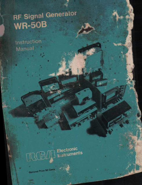
The RCA WR-50B RF Signal Gen-erator is an all-purpose instrument, designed primarily for aligning and servicing radio and television receiv-ers. The generator produces tunable RF output from 85 kc to 40 Mc, 40( cps audio output, and sweep output 455 kc and 10.7 Mc. A crystal-co_i-trolled oscillator is also provide I for
use with an external crystal. The variable oscillator covers the
fundamental frequencies from 85- kc to 40 Mc in six ranges. For higher frequencies, the second or "jar-
monic of the high range c use 1 .
A vernier Wiling co*. °Pp, (nits e-cise setting 'of the output 1_4!qu• ). The rf output can be modulated :h the internal 490 cps oscillators, or with an external audfo signal. The modula-tion level is adjustable.
A two-positiln attenuator switch, together withist'tvariable attenuator contreil prokritromplete adjustment of the rf outfii - vel.
Sweep output is provided at 455 kc and 10.7 Mc for sweep_ align, ant
of both am and fm if circuits. This sweep output makes it possible to obtain a continuous oscilloscope dis-play of if 'bandpass characteristics. A return-trace blanking circuit is in-cluded to provide a zero-reference line.
The crystal oscillator circuit in the WR-50B enables the instrtufient to be used as a crystal calibrator. A con-venient crystal socket is provided on the panel. This crystal oscillator can be used as a frequency calibration reference for the variable osci1tor, or can be used directly as a crystal-controlled signal source.
The generator includes a shielded rf output cable to minimize radiation and hum pick-up.-A phono-type panel jack is provided for of input/output.
The WR-50B has brushed alumi; num panel with permanently etched two-color dial scale and markings. The instrument is readily portable, weighing just five pounds, and meas-uring only 4% inches X 5% inches X 7% inches.
Accessories Available Separately
Crystals (Order from your local RCA Parts and Accessories Distributor)
Frequency StOck Number 100 kHz • 11C100 455 kHz 11C101 1 MHz 11C102 4.5 MHz 214796 10 MHz 11C103 10.7 MHz 11C104
• 3 •

Specifications (Performance figures with'line voltage at 120 volts, 60 Hz)
Sweep Output: 455 kc, center-frequency 10.7 Mc, center-frequency Sweep width approximately 10% of
center frequency.
Variable Oscillator: Six Ranges ( fundamental frequen-cies )
A 85 kc to 200 kc B 200 kc to 550 kc C 550 kc to 1600 kc D 15 Mc to 4.5 Mc E 4 5 Mc to 14 Mc F 12 Mc to 40 Mc
RF Output ( all ranges )* 0.05 volt rms (minimum )
Dial Calibration Accuracy
Internal Modulating Frequency approx. 400 cps
Percent Modulation adjustable up to 30%
Audio Output .. .. at least 8 volts rms across 15K Toad
External Modulation Modulating Frequency .15 kc max.
°Open-circuit value. **With WR-50B tuned to 1 Mc.
With % MOD control at maximum. Varies with crystal cut and activity.
§May be re-wired for 240 V operation.
Attenuator VFO and Sweep Output
2-step 10-to-1 attenuator switch with potentiometer for fine adjustment.
Crystal Oscillator Output Additional 7-to-1 attenuator switch
Tube Complement . ... 2 RCA 12AT7
Power Supply§ Voltage Rating 105-130 volts
50/60 cps Power Consumption 15 watts
Dimensions Height 7% in. Width 5% in. Depth 4% in.
Weight 5 lbs.
Voltage Required for 30% Mod. Using 400 cps**
approx. 10 volts rms Impedance at AF IN/OUT
Connector ( 400 cps) f approx. 10K
Crystal Oscillator Maximum Output. .0.02 volts rms Internal Mod. Percentage
approx. 20%t Frequency Range. .100 kc to 15 Mc
( Fundamental)
Functions of Controls 0 TUNING DIAL — Tunes through all six ranges ( A through F) of the
variable rf oscillator. C) RANGE SWITCH — Selects 455 kc or 10.7 Mc sweep, and VFO ranges
A through F. • 4 •

RF HI/LO — Attenuates rf (VFO, crystal, and sweep) 'output when set to LO position.
C) RF ATTEN — Provides fine rf attenuation adjustment.
® XTAL OSC HI/LO — Provides additional attenuation of crystal output.
C) RF OUT 77...,14F output cable.
O XTAL–tystal socket. Accepts crystals with HC-6U type base. Inserting crystal afd lites crystal oscillator.
• MOD IN/OUT — External modulating signal can be applied through this jack when MOD switch is set to "EXT' . Provides 400 cps output when MOD switch is set to "INT".
0 PWR OFF/% MOD — Applies power when turned clockwise from "PWR OFF" position. Varies modulation level. Varies level of 400 cps output.
io VFO ON /OFF — Turns variable frequency oscillator on or off.
@ SWEEP/INT MOD/EXT MOD — Three position switch. SWEEP — Provides sweep output with retrace blanking when range switch is set to one of the sweep positions. EXT MOD — Permits external modulation of VFO or crystal oscillator. Re-moves blanking when used with sweep function. INT MOD — Modulates VFO or crystal oscillator with 400 cps signal.
• 5 •

Operation
Plug the power cord plug into a 120 volt, 60 cps AC outlet. Turn % MOD/PWR OFF control clockwise to turn the instrument on.
VARIABLE FREQUENCY OSCILLATOR ( VFO ) OUTPUT
1. Set the range switch to the range that includes the desired fre-quency, as follows:
Range
Frequency A
85 kc to.200 kc B
200 kc to 550 kc C
550 kc to 1600 kc D
1600 kc to 4.5 Mc E
4.5 Mc to 14 Mc F
14 Mc to 40 Mc
Note: Frequencies higher than 40 Mc can be obtained by using second or third harmonics of the fundamental F band frequencies. For example, the second harmonic of the F band pro-duces frequencies from 28 Mc to 80 Mc; the third harmonic produces fre-quencies from 42 Mc to 120 Mc; etc.
2. Turn the dial indicator to the desired frequency on the dial scale. Set the VFO switch to "ON".
3. If internal 400 cps modulation is desired, set the MOD switch to "INT MOD". If external modulation is to be applied, or if no modulation is desired, set switch to "EXT MOD".
4. Adjust output level with the RF/ HI/LO SWITCH and RF ATTEN control.
SWEEP OUTPUT 1. Set the range switch to "455
KC" or "10.7 MC" and the VFO switch to ON. Set the MOD switch to "SWEEP" for sweep output with retrace blanking.
2. Set MOD switch to "EXT MOD" to remove blanking for adjusting os-cilloscope phase.
3. Adjust output level with the RF HI/LO switch and the RF ATTEN control.
4. A marker can be inserted in the sweep trace by inserting a crystal of the marker frequency in the crystal socket. Adjust marker size with the XTAL OSC switch.
Refer to page 35 for further infor-mation regarding the use of sweep output.
CRYSTAL OSCILLATOR OUTPUT
1. Insert a crystal with a frequency between 100 kc and 15 Mc in the crystal socket. Use a crystal with HC-6U type base ( pin diameter, .05"; pin space, .486" ). Specify for use in parallel resonant circuit, with 32 pf loading. Crystals for several frequen-cies are „available from RCA. See page 3.
Note: Crystals with other types of basing can be used by connecting short leads from crystal pins to the socket.
• 6 •
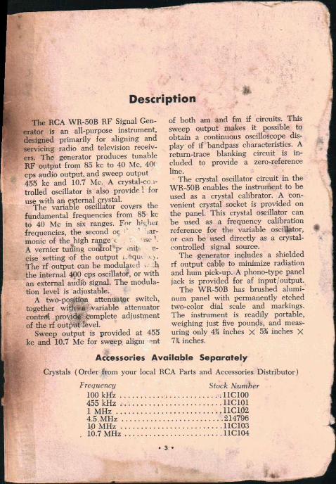
2. If the VFO is not to be used with the crystal oscillator, set the VFO switch to "OFF". Set the MOD switch to "INT" for modulation with the 400 cps internal oscillator, and to "EXT" for no modulation or if exter-nal modulation is to be applied.
3. Adjust modulation level with % MOD control. Adjust output level
with RF switch, XTAL OSC switch, and RF ATTEN control .
400 CPS OUTPUT 1. Set MOD switch to "INT MOD".
400 cps output will be available at MOD IN/OUT jack. A coaxial audio cable with standard phono plug can be used. Output level is adjustable with the % MOD control.
Crystal Oscillator
The crystal-controlled oscillator of the WR-50B is operated simply by in-serting a crystal of the desired fre-quency into the socket on the front panel of the instrument. Set the VFO ON/OFF switch to the "OFF" posi-tion to remove the variable frequency oscillator signal.
This crystal oscillator circuit fea-tures the ability to operate over a wide range of frequencies, with a rich production of harmonics. For this reason the WR-50B can be conven-iently used for calibration purposes.
For extreme accuracy, crystals which oscillate at a fundamental
mode, and are designed for operation in the type of circuit used in the WR-50B should be used. In this cir-cuit, overtone crystals will oscillate at their fundamental mode — approx-imately one-third of their designated frequency.
The WR-50B may be utilized effec-tively as a crystal-calibrated signal generator by using the crystal oscilla-tor circuitry of the instrument to cali-brate the variable oscillator.
There are several methods of using the crystal oscillator in this manner: Two of these methods are described below. In these examples a 1000 Kc
• 7 •

crystal is used, however any "fainda-mental-cut" crystal in the range from 100 Kc to 15 Mc can be used in a similar manner.
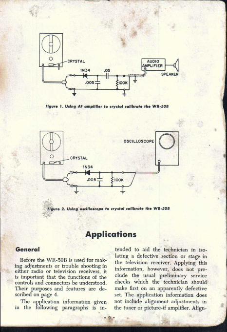
Example 1: Connect the RF OUT cable of the WR-50B to a diode cir-cuit as shown in Figure 1. Connect the diode circuit to an audio amplifier and speaker. The amplifier circuit of a radio receiver having two stages of audio amplification can be used for this purpose. If a receiver is used, connect the diode circuit to the vol-ume control, using shielded wire.
Set the RF ATTEN control fully clockwise, the RF HI/LO switch to "HI", the MOD switch to "EXT", and the VFO ON/OFF switch to "ON". Insert a 1000 Kc crystal into the socket on the front panel of the WR-50B. Turn the Range switch to "C", and tune the dial indicator be-tween 950 Kc and 1050 Kc. A zero-beat will be heard in this area.
NOTE: A zero-beat can be identi-fied as follows: As the dial approaches the zero-beat point, the sound starts from a high pitch, then reduces in frequency until it reaches "zero" and little or no sound can be heard. As the dial indicator passes beyond the zero-beat point, the sound again raises in pitch to beyond audibility.
The zero-beat occurs when the fre-quency of the variable oscillator is the same as the fundamental crystal frequency. Thus, this zero-beat point indicates the WR-50B variable oscil-lator is set at exactly 1000 Kc.
Since the Pierce-type crystal oscil-lator used in the WR-50B is rich in harmonics as mentioned above, the variable oscillator can be calibrated in a similar manner using the har-monics of the fundamental crystal frequency, such as 100 Kc, 125 Kc, 250 Kc, 333 Kc, 500 Kc, and 2 Mc, 3 Mc, 4 Mc, etc.
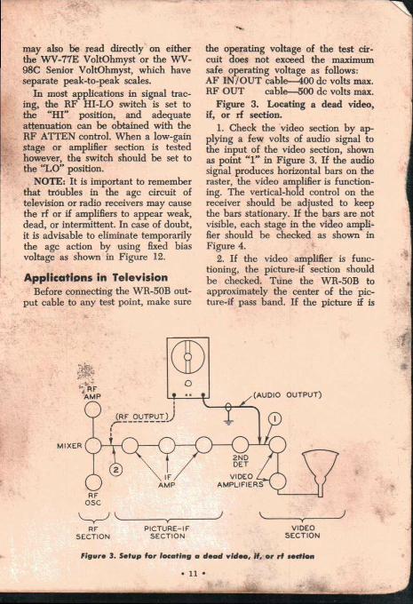
Example 2: The calibrating method described below is similar to that of example 1, except that an oscilloscope rather than an amplifier is used as the zero-beat indicator. The equipment is connected as shown in Figure 2.
Set the internal sweep of the oscil-loscope to one of the high horizontal sweep ranges, with the internal sync "off". As the variable oscillator of the WR-50B is tuned in close to the crystal frequency, a "band-type" trace will be noted. At actual zero-beat, the band changes to a straight line. As the variable oscillator is turned past zero-beat, the band again ap-pears until the beat frequency be-comes high enough to be out of the scope and detector response range.
• 8
SPEAKER
Figure 1. Using AF amplifier to crystal calibrate the WR-508
OSCILLOSCOPE
CRYSTAL
1100K
o
1
''Flour* 2. Using oscilloscope to crystal calibrate the wit-508
Applications
General
Before the WR-50B is used for mak-ing adjustments or trouble shooting in either radio or television receivers, it is important that the functions of the controls and connectors be understood. Their purposes and features are de-scribed on page 4.
The application information given in the following paragraphs is in-
tended to aid the technician in iso-lating a defective section or stage in the television receiver. Applying this information, however, does not pre-clude the usual preliminary service checks which the technician should make first on an apparently defective set. The application information does not include alignment adjustments in the tuner or picture-if amplifier. Align-

ment of these sections requires use of precision alignment equipment, such as an RCA WR-69A TV Sweep Gen-erator, WR-99A Crystal-Calibrated Marker Generator, and an oscilloscope, such as the RCA WO-33A or WO-91A.
In checking a defective receiver, make a visual inspection first. Look for unlighted or loose tubes, cold solder joints, and mechanical defects.
If picture or raster trouble is en-countered on a television receiver, the ion-trap magnet, brightness control, focusing magnet, and drive control should first be checked to see whether a normal raster with normal brightness can be obtained. A normal raster indi-cates that the kinescope, high-voltage section, vertical deflection circuits, and horizontal-deflection section are oper-ating properly. If no raster or a poor raster is obtained, these sections should be checked and corrected. When a normal raster is obtained, apply pic-ture signal and set the contrast con-trol to the maximum contrast position. If no picture is present or is weak, the trouble is probably in the rf, if or video sections.
Generation of Horizontal Bars When the internal audio oscillator
is used to amplitude modulate the rf output signal, the WR-50B is ex-tremely useful in checking picture-if and video amplifiers. Because the fre-quency of the audio signal is approxi-mately 400 cps, six horizontal bars will be produced when the vertical oscillator in the receiver is operating at approximately its normal rate of 60 cps.
Some if amplifiers operate at fre-quencies which are above the funda-mental tuning range of the WR-50B. In these cases, it will be necessary to tune the WR-50B to a frequency
which will give a harmonic at the de-sired frequency. For signal tracing if amplifiers, harmonic output from the WR-50B is more than adequate for producing useable bars on the kine-scope screen.
It will be noticed that when the WR-50B is used to produce horizontal bars, the shading of the bars may be varied from light to dark by adjust-ment of the % MOD/AF and the RF ATTEN control. These controls may be used to advantage in checking for stage gain and in isolating a defective stage in an amplifier section. For ex-ample, as the % MOD/ AF control is varied, the degree of modulation of the rf output signal is changed. In servicing work, certain modulation percentages have been accepted. For example, a modulation percentage of 30% is customarily used in general laboratory work on radio receivers and transmitters, and up to 50% is usually satisfactory for radio and television servicing applications. A high per-centage is desirable for television to provide maximum bar intensity with-out causing overload of the picture-if amplifier.
Methods of Checking Output
If it is desired to check the modu-lation percentage of the rf output signal from the WR-50B directly, it may be checked by observing the out-put waveshape on an oscilloscope, pro-viding the rf frequency is within the frequency range of the oscilloscope. As the % MOD control is varied, the degree of modulation on the wave-form will be seen to change. The oscilloscope and direct probe may also be used to measure the peak-to-peak value of the audio voltage at the AF IN/OUT connector. The peak-to-peak value of the audio output voltage
• 10 •
MIXER
AMP •
RF OSC
(RF OUTPUT O
• • • • • AMP AMPLIFIERS
111 2ND DET
IF VIDEO 4 (AUDIO OUTPUT)
may also be read directly on either the WV-77E VoltOhmyst or the WV-98C Senior VoltOhmyst, which have separate peak-to-peak scales.
In most applications in signal trac-ing, the RF HI-LO switch is set to the "HI" position, and adequate attenuation can be obtained with the RF ATTEN control. When a low-gain stage or amplifier section is tested however, the switch should be set to the "LO" position.
NOTE: It is important to remember that troubles in the agc circuit of television or radio receivers may cause the rf or if amplifiers to appear weak, dead, or intermittent. In case of doubt, it is advisable to eliminate temporarily the agc action by using fixed bias voltage as shown in Figure 12.
Applications in Television Before connecting the WR-50B out-
put cable to any test point, make sure
the operating voltage of the test cir-cuit does not exceed the maximum safe operating voltage as follows: AF IN/OUT cable--400 dc volts max. RF OUT cable-500 dc volts max.
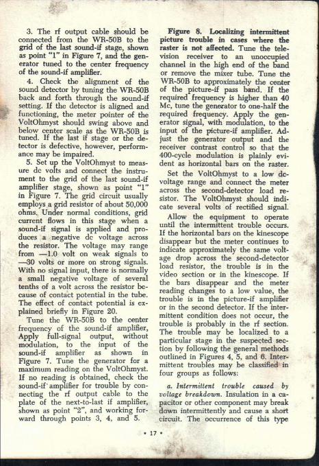
Figure 3. Locating a dead video, if, or rf section.
1. Check the video section by ap-plying a few volts of audio signal to the input of the video section, shown as point "1" in Figure 3. If the audio signal produces horizontal bars on the raster, the video amplifier is function-ing. The vertical-hold control on the receiver should be adjusted to keep the bars stationary. If the bars are not visible, each stage in the video ampli-fier should be checked as shown in Figure 4.
2. If the video amplifier is func-tioning, the picture-if section should be checked. Tune the WR-50B to approximately the center of the pic-ture-if pass band. If the picture if is
RF PICTURE-IF
VIDEO SECTION SECTION
SECTION
Figure 3. Setup for locating a dead video, if, or rf section
• 11 •

TO 2ND
DETECTOR
1ST VIDEO VIDEO OUTPUT STAGE STAGE
(PEAKING COILS OMITTED FOR SIMPLICITY)
OUTPUT)
higher than 40 Mc, tune the WR-50B to one half the required frequency; the second harmonic will provide the necessary signal. Feed a modulated rf signal to the input of the victure-if amplifier, shown as point "2 '. If the amplifier is functioning, the input sig-nal should produce horizontal bars on the raster. If the bars are not visible, check the agc voltage as described in the manufacturer's service notes. If any tubes in the if amplifier are shorted, or if the agc bus is shorted, waveshape clipping may occur in the if amplifier. If the age circuit appears to be functioning normally, each stage in the picture-if amplifier should be checked as described in Figure 5.
3. If both the video and picture-if sections are functioning, the difficulty probably lies in the rf section, which should be checked as shown in Fig-ure 6.
Figure 4. Locating a dead stage in the video amplifier.
1. Check the input circuit to the kinescope by applying the full audio
output of the WR-50B as shown at point "1" in Figure 4. The audio sig-nal should produce horizontal bars on the raster. With normal raster bright-ness, the bars produced by the audio signal in this step should be grey in tone, not black.
When the audio signal is applied to any portion of the video amplifier that comes after the sync take-off point, it will not be possible to sync the bars (keep them from rolling). The location of the sync take-off point may differ in different receivers. In some receivers it may come after the second detector, in others it may fol-low the first video stage. Other re-ceivers may have the take-off point located after the second video stage.
2. Check the coupling capacitor, shown as C3 in Figure 4, by shifting the output cable from the WR-50B from point "1" to point "2". The hori-zontal bars may become weaker or lighter in shading. If the shadowing becomes extremely light or if the bars disappear, C3 may be defective.
Figure 4. Setup for locating a dead stag. In the video amplifier
• 12 •

3. Check the video output stage by applying the full audio output from the WR-50B to the grid circuit, shown as point "3" in Figure 4. The bars should become noticeably darker, in-dicating that the stage is functioning and providing amplification. If neces-sary, reduce the audio output from the WR-50B to prevent overloading of the amplifier.
4. Check the coupling capacitor to the output stage by shifting the out-put cable from point "3" to point "4". The intensity of the bars should re-main nearly the same. If the bars be-come considerably lighter or dis-appear, C2 may be defective.
5. With the output cable connected to the plate of the first video stage,
shown as point "4" in Figure 4, reduce the audio output until the bars on the kinescope become light grey. Shift the output cable to the grid of the first stage, shown as point "5". The bars should become much darker, indicating that the first stage is functioning and providing amplification.
6. Check coupling capacitor Cl by shifting the output cable from point "5" to point "6' . The intensity of the bars should remain nearly the same. In direct coupled video amplifiers which do not use coupling capacitors, steps 2, 4, and 6 should be omitted.
Figure 5. Locating a dead stage in the picture-if amplifier.
Adjust the receiver to obtain a normal raster with normal brightness.
MIXER
I ST IF 2ND IF 3RD IF
2ND AMP AMP AMP
DET
PICTURE-IF AMPLIFIER
Figura 5. Stoop for locating a &mod stare in ant picture-if ampliflor

Set the contrast control to the maxi-mum-contrast position. Tune the re-ceiver to an unused high-frequency channel such as 12 or 13 or tempo-rarily remove the rf-oscillator tube.
Tune the WR-50B to approximately the center of the picture-if pass band. If the frequency is higher than 40 Mc, tune the WR-50B to one half the re-quired frequency; the second harmonic of the generator will supply a signal at the required frequency.
1. Adjust the generator for maxi-mum rf output with modulation ap-plied. Connect the output cable to the.grid circuit of the last picture-if amplifier, shown as point "1" in Figure 5. The 400-cycle modulation should produce horizontal bars on the raster. Adjust the vertical-hold control on the receiver to lock the bars stationary on the kinescope screen. Presence of the bars indicates that the last picture-if amplifier and second detector stages are functioning.
4. If all the picture-if stages are functioning properly, check the mixer stage by applying the rf signal to the grid of the stage, shown as point "4". In some receivers, the rf tuned cir-cuits act as a partial if short across the converter grid. In such cases, it may be necessary to remove the short during the procedure in step 4 by em-ploying one of the following methods:
a. In tuners of the turret type, re- -
• 14
2. If the shading of the bars is dark, reduce the rf output level from the WR-50B until the bars appear light grey. Move the output cable to point "2". The bars should become darker, indicating that the second if-amplifier stage is functioning.
3. The remaining stages in the pic-ture-if amplifier should be checked in the same way.
move one of the mixer coil strips and turn the turret to the blank position.
b. Using a spare mixer tube, care-fully bend out the grid pin for connec-tion to the signal generator. In this step, and sometimes in step "a", it will be necessary to use a resistor of about 10,000 ohms or larger to ground to furnish a dc-return path for the grid current.
Figure 6. Locating a dead rf-ampli-fier or rf-oscillator stage.
If the previous checks show that the picture-if and video amplifier sections are functioning properly, the rf sec-tion should next be checked for trouble.
1. Check to determine whether the rf oscillator is operating by measuring the developed negative grid-bias in the oscillator circuit. It is important that a vacuum-tube voltmeter, such as an RCA VoltOhmyst having an iso-lating probe, be used for this measure-ment. The correct value of the bias voltage should be obtained from the service notes for the receiver being tested. The voltage usually ranges from —2 to —6 volts. If the measured volt-age is a few tenths of a volt or less, it may be assumed that the rf oscil-lator is not functioning and the tube, components, and supply voltages in the oscillator circuit should be checked to determine the source of the trouble.
2. If the rf oscillator is functioning properly, the rf amplifier should be checked as follows:
Tune the receiver to channel 2 and tune the WR-50B to approximately 28 Mc with modulation applied. The 28-Mc setting of the WR-50B supplies a second harmonic of 58 Mc, which falls near the center of channel 2. Apply the modulated rf signal to the grid of the mixer tube, shown as point "2" in
•
_AK

(2F HARMONIC OUTPUT)
RF AMP MIXER
Figure 6. Sinop for locating a dead rf-amplitlor or rf-oscillator stag*
Figure 6. Adjust the rf output from the generator so that the bars are plainly visible on the kinescope screen.
NOTE: On some tuners, usually those which employ a pentode-type mixer, connection of the output cable will not cause serious detuning of the high-impedance circuits. Tuners which employ triode mixers, however, may require that a capacitor of approxi-mately 5 FAf or less be connected in series with the rf lead of the cable to minimize circuit loading. If serious detuning occurs with either type of tuner, however, it may be necessary to experiment with various methods of signal injection to avoid upsetting cir-cuit impedance.
3. Shift the output cable to the plate of the rf amplifier, shown as
point "3". The bars may become slightly lighter. If the bars become very faint or disappear, the trouble may lie in the rf tuned circuits be-tween the rf-amplifier plate and the converter grid.
4. With the output cable connected to the plate of the rf amplifier, adjust the rf output from the WR-50B until the bars are light grey. Shift the out-put cable to the grid of the rf ampli-fier, shown as point "4". The bars should become darker, indicating that the rf amplifier is functioning.
5. Shift the output cable to the an-tenna input terminal of the receiver, shown as point "5". The intensity of the bars should remain approximately the same as in step 4 above. If the bars become very faint or disappear,
• 15.•

1ST SOUND, j IF AMP
1 1
RF OUTPUT)
3RD SOUND IF AMP
POINT
2ND SOUND
IF TRANS
(TO LOAD RESISTOR)
1ST SOUND
IF TRANS
AF UT
Figure 7. Method for localizing a dead stage in the sound-if amplifier
circuits ahead of the rf amplifier should be checked for trouble.
These methods for localizing trouble in the tuner have certain limitations. For thorough and accurate trouble-shooting work on tuners, standard sweep-alignment equipment should be used. An RCA WR-69A Television Sweep Generator, and RCA WR-99A Crystal-Calibrated Marker Generator, and the RCA WO-33A or WO-91A Oscilloscopes are recommended.
Figure 7. Localizing a dead stage in the sound-if amplifier.
If the picture is normal but sound is out on all channels, the trouble will probably be found in the sound circuits following the sound-if take-off
circuit. The location of the sound-if take-off circuit will differ with dif-ferent receivers; it may follow the converter stage or one of the picture-if amplifiers. It may also come after the second detector or one of the video amplifiers.
1. Check the audio section of the receiver to determine whether it is functioning, as described in Figure 14.
2. If the audio section is function-ing properly, the FM sound detector should be checked next. In either the ratio or discriminator type detectors, the VoltOhmyst should be set up to use the zero-center scale and con-nected across the output load resistor of the detector.
• 16
3. The rf output cable should be connected from the WR-50B to the grid of the last sound-if stage, shown as point "1" in Figure 7, and the gen-erator tuned to the center frequency of the sound-if amplifier.
4. Check the alignment of the sound detector by tuning the WR-50B back and forth through the sound-if setting. If the detector is aligned and functioning, the meter pointer of the VoltOhmyst should swing above and below center scale as the WR-50B is tuned. If the last if stage or the de-tector is defective, however, perform-ance may be impaired.
5. Set up the VoltOhmyst to meas-ure dc volts and connect the instru-ment to the grid of the last sound-if amplifier stage, shown as point "1" in Figure 7. The grid circuit usually employs a grid resistor of about 50,000 ohms. Under normal conditions, grid current flows in this stage when a sound-if signal is applied and pro-duces a negative dc voltage across the resistor. The voltage may range from —1.0 volt on weak signals to —30 volts or more on strong signals. With no signal input, there is normally a small negative voltage of several tenths of a volt across the resistor be-cause of contact potential in the tube. The effect of contact potential is ex-plained briefly in Figure 20.
Tune the WR-50B to the center frequency of the sound-if amplifier, Apply full-signal output, without modulation, to the input of the sound-if amplifier as shown in Figure 7. Tune the generator for a maximum reading on the VoltOhmyst. If no reading is obtained, check the sound-if' amplifier for trouble by con-necting the rf output cable to the plate of the next-to-last if amplifier, shown as point "2", and working for-ward through points 3, 4, and 5.
Figure 8. Localizing intermittent picture trouble in cases where the raster is not affected. Tune the tele-vision receiver to an unoccupied channel in the high end of the band or remove the mixer tube. Tune the WR-50B to approximately the center of the picture-if pass band. If the required frequency is higher than 40 Mc, tune the generator to one-half the required frequency. Apply the gen-erator signal, with modulation, to the input of the picture-if amplifier. Ad-just the generator output and the receiver contrast control so that the 400-cycle modulation is plainly evi-dent as horizontal bars on the raster.
Set the VoltOhmyst to a low dc-voltage range and connect the meter across the second-detector load re-sistor. The VoltOhmyst should indi-cate several volts of rectified signal.
Allow the equipment to operate until the intermittent trouble occurs. If the horizontal bars on the kinescope disappear but the meter continues to indicate approximately the same volt-age drop across the second-detector load resistor, the trouble is in the video section or in the kinescope. If the bars disappear and the meter reading changes to a low value, the trouble is in the picture-if amplifier or in the second detector. If the inter-mittent condition does not occur, the trouble is probably in the rf section. The trouble may be localized to a particular stage in the suspected sec-tion by following the general methods outlined in Figures 4, 5, and 6. Inter-mittent troubles may be classified in four groups as follows:
a. Intermittent trouble caused by voltage breakdown. Insulation in a ca-pacitor or other component may break down intermittently and cause a short circuit. The occurrence of this type
• 17 •

O
o o 0 0
• • 0
(RF OUTPUT)
PICTURE-IF
& 2ND DET
VIDEO
AMP
Figure 8. Method for localizing intermittent picture trouble
of trouble can usually be accelerated for service purposes by operating the receiver at higher-than-normal line voltage, such as 125 volts. The RCA TV Isotap, a combination isolation and adjustable-voltage transformer, is extremely useful for this purpose.
b. Intermittent trouble caused by mechanical expansion and contraction due to temperature changes. Connec-tions inside tubes, capacitors, resis-tors, transformers, and other com-ponents may open up or become shorted as a result of expansion and contraction due to temperature changes as the receiver warms up or cools off with application and removal of power. The occurrence of such trouble can often be speeded up by heating the components in the suspected section. An ordinary electric lamp or an infra-red lamp may be used.
c. Intermittent contacts. If the inter-mittent trouble, occurs when the chassis is tapped, shaken, or twisted slightly, the trouble is probably due to an intermittent contact, such as (1)
an unsoldered joint, (2) a cold-soldered joint, (3) a stray strand of wire, (4) a stray lump of solder, or (5) a bare wire too close to another bare wire, or too close to a bare con-tact, etc. This type of trouble is usu-ally located by tapping, pushing, or pulling gently on connections and components in the suspected section of the receiver.
d. Intermittent rf oscillator action due to low line voltage. The rf oscilla-tor may have a tendency to stop oscil-lating when the line voltage is lower than normal. When the rf oscillator stops working, both the sound and picture will be absent. The oscillator may function when the receiver is first turned on and then stop when the receiver is tuned to a different fre-quency. A weak or faulty oscillator or power rectifier, or dirty tuner contacts contribute to the condition. In cases where there is reason to suspect this trouble, it is advisable to check re-ceiver operation at a line voltage which
continued on page 22
• 18 •

Replacement Parts List When ordering replacement parts, include model and serial number of "nstrument.
Parts should be ordered through a local RCA electronic instruments distributor.
Symbol No. Description Stock No.
Capacitors C-1, C-6 Trimmer, 1.5-10 pf 219975
C-7 Ceramic, 12 pf, 10%, 500 V 235386
C-8 Variable, 10-330 pf 226326
C-9, C-11 Ceramic, 3.3 pf, 20%, 500 V 235385
C-10 Mica, 120 pf, 20%, 500 V 59481
C-12, C-14, C-18, Ceramic, .005 A f , GMV, 500 V 73473
C-24 C-13 Paper, 0.1 pf, 200 V 228040
C-15, C-27 Ceramic, .001 pf, GMV, 500 V 77252
C-16, C-19 Ceramic, 47 pf, 20%, 500 V , 227754
C-17 C-20, C-21
Paper, .033 pf, 400 V Ceramic, .01 pf, 20%, GMV, 500 V '
227885 73960
C-22 Paper, 0.1 µf , 400 V 227530
C-23 Electrolytic, 40/40 pf, 150 V 226327
C-25 Paper, 0.1 pf, 100 V 228040
C-26 Paper, .047 pf, 400 V 227754
Resistors R-1 22 K, 10%, 1/2 watt 502322
R-2, R-11 47 K, 10%, '/2 watt 502347
R-3 68 K, 10%, 1/2 watt 502368
R-4 120 K, 10%, '/2 watt 502412 R-5, R-15 330 ohms, 10%, '/2 watt 502133 R-6 33 ohms, 10%, 1/2 watt 502033
R-7 100 ohms, 10%, 1/2 watt 502110 R-8 Variable, 500 ohms 226433 R-9 Variable, wire wound, 2500 ohms 235384 R-10 180 ohms, 10%, 1/2 watt 502118 R-12 470 K, 10%, '/2 watt •502447 R-13, R-21 100 K, 10%, 1/2 watt 502410 R-14 2700 ohms, 10%, '/2 watt 502227 R-16, R-17 1.5 meg, 10%, 1/2 watt 502515 R-18 390 ohms, 10%, 1/2 watt 502139 R-19 180 K, 10%, '/2 watt 502418 R-20 Variable, 15 K, w/switch S-6 235378 R-22 1000 ohms, 10%, 1 watt 512210 R-23 6800 ohms, 10%,• 1/2 watt 502268 R-24 2200 ohms, 10%, '/2 watt 502222 R-25 560 ohms, 10%, 1/2 watt 502156
Coils L-1 85-200 kc 226378 L-2 200-550 kc 226329 L-3 550-1700 kc 226330 L-4 1.5-4.5 mc 226331 L-5 4.2-14 mc 226332 L-6 12-40 mc 226333 L-7 550 kc 226329 L-8 10.7 mc 235387
Miscellaneous CR-1 Diode, type IN3756 235382 CR-2 Diode, type IN3754 229040 CR-3 Diode, varactor 235383 S-1 Switch, range 235380 S-2 Switch, slide, SPDT 101247 S-3, S-4 Switch, slide, SPDT 235381 S-5 Switch, slide, DPDT 227560 S-6 Part of R-20
98192 T-1 Power transformer Ti VI Power transformer for VI units (240 V) 246333 T-2 Audio transformer 226325
Case assembly 235379 Connector, MOD IN/OUT 232121 Handle 226241 Knob, pointer 212148 Knob, black rubber 94878 Knob, w/set screw 226689 Pilot light 229727 Indicator assembly 227583 Crystal socket 56262 Shell, for probe (2 pieces) 219485

C II
R9 2500
SWEEP LINEARITY
BAND D 2 L4 I.5MC ..7-..
TO ' C4 a
4.5MC 1.5-10 ..-1
-1.- ...1
RI2 C19 47
4701 LS CA ICA
4 R11
7K
X TAL
L6
0 C6
1.5-10
10
3.3
VIA • 12AT7 68
R3 K
VFO 60V 6
455 KC SWEEP
10.7 MC SWEEP
BAND A 85KC
TO 200KC
BAND B 200KC
TO 550KC
BAND C 550 KC
TO 1600KC
C R3 VAR. CAP.
DIODE
C12
I 47K
S2 V FO
R13 100K
C47 T + 6V. -
.005
R2
V2A
12AT7 CRYSTAL 0 SC.
NOTES: VOLTAGES MEASURED WITH AN RCA VOLTOHMYST ® WITH CONTROLS SET AS FOLLOWS:
RANGE SW. (S1)-BAND F %MOD — MAX. CW FREQUENCY— 12 MC RF ATTEN.-MAX. CW R F HI NO XTAL IN SOCKET MOD IN VFO ON VOLTAGES MAY VARY ±20% FROM VALUES SHOWN
TRADE MARK ® REGISTERED MARCA(S) REGISTRADA(S)
®DENOTES SCREW DRIVER ADJUSTMENTS.
ALL SWITCHES SHOWN IN MAX CCW POSITION AND VIEWED FROM FRONT.
•ALL RESISTORS IN OHMS AND ARE 1/2 WATT UNLESS OTHERWISE NOTED.
j_ DENOTES CHASSIS CONNECTION.
* 3 WIRE LINE CORD US, UNITS. UNITS DESIGNATED'WR-5013 VI 0 POWER TRANSFORMER THAT CAN BE WIRED FOR 120V QR 240V OPERATIOI
• 20 •
BAND F 12 MC
TO 40MC
120VAC
50/60'1/ =
c 21°' .0
I.5V AC
R25 560
BAND E 4.5 MC
TO / C5 14 MC 1.5-10
•
ON .44
OFF

FOR 120V OPERATION: T1 V1B
12AT7 CATHODE FOLLOWER
120V AC
INPUT
R7 100
R8 500
RF ATTEN.
LOCATED IN PLASTIC SHELL
C15 .001
RF OUT
FOR 240V OPERATION:
C17 .033 1801(
SAO. +150V
TI CR2
IN3754 LAMP
DIODE
Li
S4 91_0 XTsAcL I OSC
R15 330
+130V V2B
12AT7 6 AUDIO OSC.
BLANKING AMP
R14 a 2700 S5A R16 R17 R18
SWEEP 1.5M I.5M 390 EXT
7 MODI
INT GRN REDT2 BLU R2
2200
C25 .1
1001.1 BLU/YEL
240V AC
INPUT
L NOTE
THE NEON INDICATOR IS CONNECTED TO ONE OF THE PRIMARIES FOR LONGER UPC AT 240V OPERATION.
MOD. IN/OUT
S58 SWEEP
EXT MOD. INT
R5K02
I _ %MOD
R23 C22
-F—X0A(c,c
ler". R21
' 100K
56 1 ER ON OF R20
.1 400V.
RED CR1
IN3756 C23A
E 40 MFD. RED/YEL
o GRN.
GRN/YEL
jr
T.005 C24
R22 1000
1W
+150V
4 5 4,5
C23B 40 MFD.
V2
C26 .047
256674
• 21 •

\--1••• SOUND IF AMP
SOUND DETECTOR
AUDIO AMP
41%, 1,7,
0 ••
0 0
0 0
RF OUTPUT
LOUDSPEAKER
figure 9. Method for localizing Intermittent sound trouble
is slightly less than the lowest voltage encountered in that particular loca-tion. THE RCA WP-25A TV Isotap is extremely useful in detecting this intermittent trouble.
Figure 9. Localizing intermittent sound trouble. If the picture is normal but the sound is intermittently dead, the trouble is probably in the sound-if or audio section. In receivers having a separate sound channel, a shift in the frequency of the rf oscillator can pro-duce somewhat similar symptoms.
With the VoltOhmyst set to the 50-volt dc range, connect the instru-ment to the output of the sound-if detector. Connect the rf output cable of the WR-50B with modulation applied, to the input of the sound-if amplifier. Tune the WR-50B slightly above or below the correct frequency for great-est positive or negative indication on the VoltOhmyst. Advance the receiver volume control and reduce the output from the generator to bring the if signal slightly below limiting level. Readjust the volume control for the desired sound level.
Allow the equipment to operate
until the intermittent trouble shows up. Occurrence of the trouble can often be speeded up as described in the text for Figure 8. If the sound disappears but the meter reading re-mains approximately the same, the trouble must be in the audio section. If the meter reading drops to a low value, the trouble is in the sound-if amplifier or detector.
The trouble may be localized to a particular stage by applying the gen-eral method described in Figures 7 and 14. These methods may also be used to localize intermittent troubles in FM radio receivers.
Figure 10. Checking approximate stage gain in a video or audio ampli-fier. Remove or disable one of the if tubes so that external signals cannot reach the video or audio amplifier. Set up the VoltOhmyst to measure ac voltage. Set up the WR-50B to deliver audio output. If the video amplifier has a contrast control, set the control for maximum gain.
1. Connect the rf output cable of the signal generator to the grid of the out-put tube, shown as point "1". Connect
• 22 •

the VoltOhmyst to the same point. Ad-just the generator to produce 1.0 rms volt of signal at. the grid. Shift the VoltOhmyst to the plate and measure the audio signal voltage at the plate. The approximate voltage gain is equal to the numerical value of the signal voltage at the plate. For example, with 1.0 volt of signal at the grid and 15 volts of signal afthe plate, the approxi-
15 mate gain ilopeogual to — or 15.
1 In ac/dc radio receivers and in
some small ac receivers, considerable hum voltage, up to 10 or 15 volts, may be present at the plate of the output tube. To minimize error due to the hum voltage, it is necessary to measure the hum voltage separately at the plate and subtract the hum voltage from the previous reading. The hum voltage should be measured without application of an audio signal. When checking the gain of an audio-output stage, it is essential to have the speaker connected to the output trans-former because the gain of the output stage without a load is much higher than normal.
2. The gain of the first stage should be measured in the same manner.
Figure 11. Checking approximate stage gain in a picture-if amplifier. The agc circuit should first be rendered inoperative as described in Figure 12. Set up the VoltOhmyst to measure de voltage and connect the VoltOhmyst across the second-detector load resistor.
1. Connect the rf output cable of the WR-50B to the grid of the last pie-hire-if tube, shown as point "1" in Figure 11. Tune the WR-50B to a frequency in the picture-if pass band for maximum indication on the meter. Adjust the output (without modula-tion) to produce 0.5 volt across the load resistor.
2. Shift the output cable to the grid of the next-to-last if amplifier, shown as point "2". The meter reading should change by a factor equal to the gain of the next-to-last stage. For example, if the meter reading increases from 0.5 volt to 2.5 volts, the approxi-
2.5 mate gain is equal to — = 5.
0.5 After determining the gain, and
with the generator output cable con-nected as in step 2, reduce the output to produce 0.5 volt across the load resistor.
(„(D
AUDIO OR VIDEO AMP
0 0
(13 •
Figure 10. Setup for making approximate stage gain check in video or audio amplifier
• 23 •

2ND DE T LOAD RESISTOR IF AGC BUS
(RF OUT PUT) O 0
O 0
® COUPLING CIRCUIT
COUPLING CIRCUIT
COUPLING CIRCUIT
COUPLING CIRCUIT
0
PICTURE IF AMPLIFIER
PICTURE DETECTOR
Figure 11. Setup for making approximate stage gain cheek in picture-if amplifier
3. Shift the output cable to the grid of the second-from-last stage. The
• meter reading should change by a factor equal to the gain of the stage..
Check any remaining stages in the same manner.
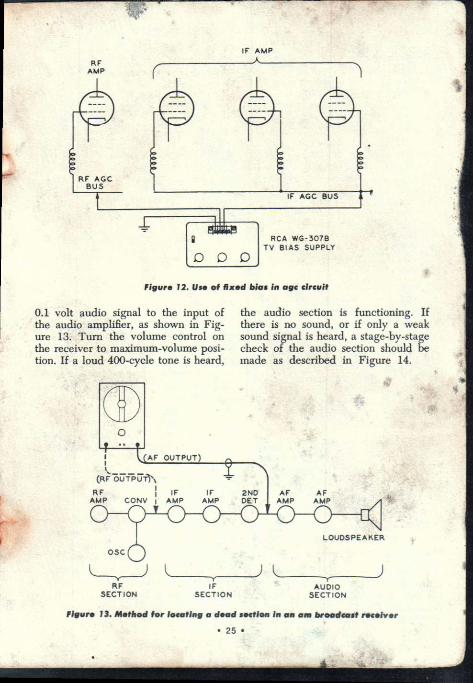
Figure 12. Eliminating AGC action when checking gain in rf and if amplifiers.
The procedure for locating a dead or exceedingly weak stage has been shown abolk. In cases where the re-ceiver is not dead but performance is definitely weak, the WR-50B can be used to locate the faulty stage by measuring the, approximate gain of each stage.
To measure rf and it gain in re-ceivers employing agc, it is almost a necessity to eliminate agc action by applying a fixed bias voltage to the
• 24
rf and if amplifiers. The RCA WG-30713 TV Bias Supply is ideally suited to this purpose. If the manufac-turer describes a method in his service notes, his method should be followed. A typical method, however, is shown in Figure 12. For gain measurements, the rf and if amplifiers should be operated at nearly maximum gain by using a low bias voltage. A bias of —1.5 volts is generally satisfactory. In high-gain amplifiers or in noisy locations, it may be necessary to lower the gain by using a'bias of —3 volts.
Applications in Radio Servicing
Figure 13. Locating a dead section in an AM broadcast receiver.
1. Check the audio section of the receiver by applying approximately
RF AMP
RF AGC BUS
RCA WG-307B TV BIAS SUPPLY
IF AGC
IF AMP
2ND DET
AF OUTPUT)
ortZr.iii.t7fis% RF j IF AMP CONV I AMP
AF AF AMP AMP
IF AMP
Figure 12. Use of Fluent bias in age circuit
0.1 volt audio signal to the input of the audio amplifier, as shown in Fig-ure 13. Turn the volume control on the receiver to maximum-volume posi-tion. If a loud 400-cycle tone is heard,
the audio section is functioning. If there is no sound, or if only a weak sound signal is heard, a stage-by-stage check of the audio section should be made as described in Figure 14.
LOUDSPEAKER
OSC
RF
IF AUDIO SECTION
SECTION SECTION
Figura 13. M.thod for locating a dead soctien in an am broadcast muds's
• 25 •

2. If the audio section is function-ing, the if section should be checked by applying an if signal of very low level with modulation to the input of the if amplifier, as shown in Figure 13. Tune the WR-50B to the if of the receiver, which is 455 Kc in most cases. If a loud 400-cycle tone is heard, it indicates that the if section is funtioning. If no signal is heard, or if the sound is weak, a stage-by-stage check of the if amplifier should be made a& described under Figure 15.
3. If both the audio and if sections of the receiver are functioning, it may be assumed that the difficulty is in the rf section, which should be checked as shown in Figure 17.
Figure 14. Locating a dead stage in the audio amplifier of a radio or television receiver.
1. Check the speaker and output transformer by applying the full audio-output signal of the WR-50B to the primary of the output transformer, shown as point "1''. If a 400-cycle sound, signal is heard, it indicates that the speaker and transformer are func-tioning.
2. Check the audio-output stage of the receiver by applying almost the full audio output of the generator to the grid of the output tube, point "2". If a loud 400-cycle tone is produced, the output stage is functioning.
For the following steps, the volume control should be set to the maximum-volume position.
3. Check the coupling capacitor, shown as C3 in Figure 14, by shifting the output cable from the generator from point "2" to point "3" The sound level should remain approxi-
mately unchanged. If the sound level changes, the capacitor may be open or otherwise defective.
4. Check the first audio stage. With the output cable connected to the plate of the first audio tube, re-duce the audio signal level so that the 400-cycle sound is weak. Shift the generator output cable to the grid of the first audio tube, point "4". The sound should be greatly increased, in-dicating that the first stage is func-tioning.
5. Check coupling capacitor C2 by shifting the generator output cable from point "4" to point "5". The sound level should remain approxi-mately the same. Otherwise, C2 is defective.
6. Check the volume control by applying about 0.1 volt of audio sig-nal across the control. Turn the con-trol through its complete range and observe whether it provides smooth, noiseless attenuation. Noise may be caused by a defective volume control or by de leakage in either of the blocking capacitors.
7. Check the input coupling capac-itor Cl by shifting the generator lead fromyipoint "6" to point "7". The sound level should remain practically un-changed.
Figure 15. Locating a dead stage in the if amplifier of an AM broadcast receiver. If the audio section is func-tioning, the if amplifier should be checked. The receiver volume control should be set to the maximum-volume position and the WR-50B should be tuned to the intermediate frequency used in the receiver.
• 26 •

AUDIO OUTPUT STAGE
1ST. AUDIO STAGE
(AF OUTPUT)
LOUD- SPEAKER
CI
VOLUME CONTROL
C3
110 OUTPUT
TRANS
Figure 14. Method for locating a dead stage in the audio amplifier of a radio or television receiver
1. Apply an if signal, of very low level with modulation, to the grid cir-cuit of the second-if amplifier, shown as point "1". Retune the generator for peak sound output. If a loud 400-cycle sound is produced, it indicates that the second-if amplifier is functioning. If there is no sound or if the sound is weak, the trouble may lie in the sec-ond-if amplifier or second-detector circuits.
2. Check the first-if amplifier in the same manner by feeding the signal in at point "2".
3. If both stages are operating properly, check the converter stage by shifting the output cable to the grid of the converter tube, point "3". If a loud 400-cycle sound is produced, it indicates that the converter is func-tioning. If there is no sound, or if the sound is weak, the trouble may lie in the converter or in the first if trans-former.
In some receivers the rf tuned cir-
cuits may form a partial if short across the converter grid circuit. In these cases, it is necessary in step 3 to con-nect a resistor of 10,000 ohms or more between the converter grid and the rf tuned circuit. Remove the resistor after completing step 3.
Figure 16. Checking if transformers and if-coupling capacitors.
A stage-by-stage method for lo-cating a dead if-amplifier stage is shown in Figure 16 Each stage in-cludes a tube and a coupling trans-former. When a dead stage is dis-covered, it is necessary to determine whether the trouble is in the coupling transformer or in other components associated with the tube.
A rough check of the condition of the coupling transformers can be made by connecting a low-value capacitor of about 5 ppf in series with the gen-erator output lead. Capacitor leads should be kept short. The purpose of the capacitor is to reduce detuning
• 27 •
MIXER 1ST IF
AMP
2ND IF
AMP
2ND DET
Figure 15. Method for locating a dead stars In the if amplifier of an am broadcast rocolvor
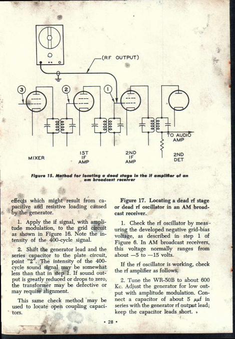
effects which might result from ca-
bacitive and resistive loading caused y the generator.
1. Apply the if signal, with ampli-tude modulation, to the grid circuit as shown in Figure 16. Note the in-tensity of the 400-cycle signal.
2. Shift the generator lead and the series capacitor to the plate circuit, point "2". The intensity of the 400-cycle sound signal may be somewhat less than that in step 1. If sound out-put is greatly reduced or drops to zero, the transformer may be defective or may require alignment.
This same check method may be used to locate open coupling capaci-tors.
Figure 17. Locating a dead rf stage or dead rf oscillator in an AM broad-cast receiver.
1. Check the rf oscillator by meas uring the developed negative grid-bias voltage, as described in step 1 of Figure 8. In AM broadcast receivers, this voltage normally ranges from about —5 to —15 volts.
If the rf oscillator is working, check the rf amplifier as follows.
2. Tune the WR-50B to about 600 Kc. Adjust the generator for low out-put with amplitude modulation. Con-nect a capacitor of about 5 Aid in series with the generator rf output lead; keep the capacitor leads short.
• 28 •

Figure 16. Method for checking if transformers and if-coupling capacitors
Connect the generator to the signal grid of the mixer tube, point "1", as shown. Tune the receiver for peak intensity of the 400-cycle sound. Ad-just the receiver volume control for a comfortable sound level.
3. Apply the same modulated 600- Kc signal to the plate of the rf tube, point "2". If the 400-cycle sound be-comes considerably weaker or dis-appears, look for trouble in the cou-pling circuit between the rf amplifier and the converter.
4. Check the rf amplifier by apply-ing the modulated 600-Kc signal to the amplifier grid, point "3". Retune the receiver slightly, if necessary, for maximum sound output. The output may increase slightly when the gen-erator is moved from the plate to the grid of the rf amplifier. If the sound becomes considerably weaker or dis-appears, look for trouble in the rf-amplifier circuit.
5. Check the antenna input coil by applying the 600-Kc signal to the an-tennt input terminal, point "4". The
• 29
sound output may increase or decrease slightly, depending on the design of the antenna coil. If the sound becomes considerably weaker, or disappears, it indicates trouble in the antenna coil.
Figure 18. Avoiding hum and shocks when checking AC/DC re-ceivers.
To avoid introduction of hum when working on ac/dc receivers, it is usu-ally necessary to connect the genera-tor ground cable to the common nega-tive bus in the receiver, NOT to the receiver chassis. To prevent the case of the generator from becoming "hot" with respect to ground when the gen-erator is connected to the common negative bus, it is necessary either to use a capacitor of about 0.05 Af, 600 volts rating in series with the genera-tor ground lead or, preferably, to use an isolation transformer, as shown in Figure 18. The RCA WP-25A TV Isotap is well suited to this applica-tion. The Isotap may be used to iso-late small ac/dc radio receivers and transformerless television receivers
•

RF AMP w MIXER
Figure 17. Method for locating a dead rf or oscillator stage in an •am broadcast receiver
from the power line and other equip-ment on the service bench.
Figure 19. Checking the gain of an if amplifier in an AM broadcast receiver.
Eliminate the age action, as de-scribed in Figure 12. Set up a Volt-
Ohmyst to measure dc voltage. Con-nect the VoltOhmyst across the second-detector load resistor, point "1" in Figure 19. Connect the output cable of the WR-50B to the grid of the first if amplifier tube, point "2". Tune the generator for peak indication on the meter.
0
WP-25A
T4110H I SOTAP
POWER LINE
00
GROUNDING POINTS
GROUND CLIP
JP' TO RECEIVER TEST POINT
I I I (GROUND BUS INSULATED
FROM CHASSIS)
AC/DC RECEIVER,
Figure 18. Use of isolation transformer in servicing of ac/dc receivers
• 30 •

AGC BUS
1. Tune the WR-50B to the re-ceiver if and adjust the output, with-out modulation, to produce 10 volts gross the second-detector load re-
4nistor. 2. Disconnect the VoltOhmyst from
the load resistor. Connect a, crystal probe to the VoltOhmyst and measure the generator output voltage at the grid of the if amplifier. The approxi-mate voltage gain is equal to
Signal voltage at 2nd-detector load resistor Signal voltage at if grid
For example, if the signal voltage at the grid is 0.1 volt, and the signal voltage at the second-detector load resistor is 10 volts, the approximate
10 gain equals: — or 100.
0.1
# For possible correction due to con-tact potential, refer to Figure 20.
Figure 20. Correcting for the effect of contact potential.
When making if gain checks, if the second detector of the receiver is a vacuum-tube diode, it may be neces-sary to correct readings for the ,effect of contact potential. The effect of con-tact potential within the tube is to produce a dc voltage across the de-tector load resistor. This volge usu-ally ranges from about 0.1 volt across a video load resistor of a few thou-sand ohms, to about 0.5 volt across an audio load resistor of about 100,000 ohms.
In gain checks which deal with a relatively weak signal at the second
(RE OUTPUT) CRYSTAL PROBE
2ND DET TO
AUDIO AMP
LOAD RESISTOR
Figure 19. Method for checking if amplifier gain in an am broadcast receiver
t BIAS BOX
• 31 •
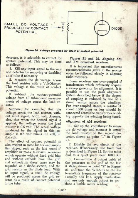
SMALL DC VOLTAGE PRODUCED BY CONTACT
POTENTIAL DIODE
figure 20. Voltage produced by effect of contact potential
detector, it is advisable to correct for contact potential. This may be done as follows:
1. Kill any input signal to the sec-ond detector by removing or disabling an if tube if necessary.
2. Measure the dc voltage across the load resistor with a VoltOhmyst. This voltage is the result of contact potential.
3. Subtract the contact-potential voltage from all subsequent measure-ments of voltage across the load re-sistor.
Suppose, for example, that the voltage across the load resistor, with-out input signal, is 0.1 volt. Assume, also, that when the desired signal is applied, the voltage across the load resistor is 0.5 volt. The actual voltage produced by the signal in this ex-ample is 0.5 volt minus 0.1 volt, or 0.4 volt.
The effect of contact potential is also evident in some limiter and ampli-fier stages, such as the last sound-if amplifier in many television receivers which operate without fixed grid bias and without cathode bias. The grid and cathode in these cases may be regarded as a diode section, and the grid resistor as the diode load. With no input signal, a small dc voltage will be produced across the grid re-sistor as a result of contact potential in the tube.
Figures 21 and 22. Aligning AM and FM broadcast receivers.
It is important that manufacturers recommendations given in the service notes be followed closely in aligning radio receivers.
Some receivers use over-coupled if transformers which ordinarily require a sweep generator for alignment. It is possible to use the peak alignment system described below if the degree of coupling is reduced by use of a shunt resistor across the windings. For over-coupled stages, a resistor of about 1000 ohms or less should be connected across the transformer wind-ing opposite the winding being tuned.
Alignment of AM receivers 1. Set up the VoltOhmyst to meas-
ure dc voltage and connect it across the load resistor of the second de-tector, shown as point "1" in Figure 21.
2. Disable the avc circuit of the receiver. If necessary, use fixed bias as described in Figure 12. Set the radio dial to a quiet point near 1600 Kc.
3. Connect the rf output cable of the generator to the grid of the last if stage, shown as point "2" in Figure 21, and tune the WR-50B to the in-termediate frequency of the receiver ( usually 455 kc ). Apply modulation and use only enough output to pro-duce a usable meter reading.
• 32 •

Figura 21. Situp for aligning am broadcast registrars
4. With a suitable alignment tool, adjust the secondary if T3 for peak indication on the VoltOhmyst. Then adjust the T3 primary for peak reading.
5. Move the rf output cable to point "3" and adjust the T2 secon-dary and primary respectively, for peak reading of the VoltOhmyst.
6. Move the rf output cable to the grid of the mixer and adjust T1 secondary and primary for peak reading ,on the VoltOhmyst.
Alignment of the receiver oscillator should be made after the if amplifier section is aligned. In am broadcast receivers, the oscillator may be aligned as follows:
1. Set up the VoltOhmyst to meas-ure dc voltage and connect it across the load resistor of the second de-tector.
2. With the receiver antenna con-nected and placed in approximately
the same position it will occupy when installed in the receiver cabinet, lay the output cable of the generator near enough to the antenna so a low level radiated signal will be picked up.
3. Tune the receiver to its highest frequency, approximately 1600 Kc for most types, and set the generator to this same frequency. With an insu-lated screw driver, adjust the trimmer capacitor on the receiver oscillator for maximum reading on the VoltOhmyst.
4. Return the generator and re-ceiver to approximately 1400 kc. Ad-just the antenna trimmer for peak indication on the meter.
5. Retune the receiver and the generator to 600 Kc, rock the tuning gang slightly, and adjust the oscil-lator coil for maximum reading on the meter.
Alignment of FM receivers — Refer to Figure 22.
• 33 •

1st. IF 2nd IF AMP AMP LIMITER DISCRIMINATOR MIXER
RATIO DETECTOR
NOTE: USE THIS SCHEMATIC
TO LOCATE TEST POINTS AND 0 IF RECEIVER
USES A RATIO DETECTOR
figuro 22. Setup for aligning fm broadcast rocoivors
1. Set the VoltOhmyst to measure DC voltage, with the meter pointer at the "Zero-Center" mark on the meter. (Use the "Zero" control to center the pointer.) Connect the Volt-Ohmyst from point "X" to ground.
2. Connect the WR-50B rf cable between the grid of the limiter tube and ground. Set the MOD switch to "OFF", the RF switch to "HI", and the RF ATTEN control fully clock-wise. Tune the WR-50B frequency to 10.7 Mc. DO NOT CHANGE THIS FREQUENCY SETTING DURING THE ALIGNMENT PROCEDURE.
3. Adjust the primary winding of T-4 for peak indication on the meter.
4. Connect the VoltOhmyst probe to point "Y". Adjust the secondary winding of T-4 for zero output (Zero-center mark on VoltOhmyst meter). Note that the meter pointer can be made to swing from + to — during this adjustment.
5. Repeat steps 3 and 4. 6. Switch the VoltOlunyst to meas-
ure —DC. Adjust the zero control to return the meter pointer to the nor-mal left-hand "0" on the scale. Con-nect the VoltOhmyst probe to point "Z".
7. Connect the WR-50B rf cable between point 2", the grid of the 2nd if tube, and ground.
8. Adjust both the primary and secondary of T-3 for peak indication on the VoltOhmyst. Note the final voltage indication at this point.
9. Connect the WR-50B rf cable between point 3", the grid of the 1st if tube, and ground. Adjust the RF ATTEN control of the WR-50B so that the VoltOhmyst indicates ap-proximately the same voluige as noted after step 8 was completed.
10. Adjust both the primary and secondary of T-2 for peak indication on the VoltOhmyst.
• 34 •

11. Connect the rf cable of the WR-50B between point "4", the sig-nal grid of the mixer or converter tube, and ground. Again, adjust the RF ATTEN control of the generator so that the VoltOhmyst indicates the voltage noted in steps 8 and 9.
12. Adjust the primary and sec-ondary of T-1 for peak indication on the VoltOhmvst.
RF Alignment Because of the various types of
tuners used in FM sets, it is recom-mended that only the RF alignment
Sweep The sweep output provided by the
WR-50B permits ehecking and align-ing both AM and FM intermediate-frequency ( IF ) amplifier circuits. Sweep alignment of the 10.7 Mc IF amplifier circuits is recommended by many manufacturers of FM receivers. Although the IF amplifiers in most AM receivers are aligned using the "peak" alignment method, the service notes for some sets, including newer transistor models, do specify sweep alignment.
Sweep alignment techniques enable the bandpass characteristics ( fre-quency response) of a tuned circuit to be observed on an oscilloscope. This is accomplished by passing the sweep signal, which consists of a band of frequencies, through the cir-cuit. Those frequencies amplified by the circuit will cause vertical deflec-tion of the oscilloscope trace, thus forming the frequency response curve of the amplifier. Through the use of frequency markers, the circuit can be aligned to produce the necessary bandpass characteristics.
The Sweep Signal A sweep signal is formed by re-
peatedly increasing and decreasing ( sweeping) the frequency of an oscillator.
• 35
procedure given by the receiver manufacturer be followed. In most cases the WR-50B can be used as a signal source in the 88-108 Mc region by utilizing the 4th harmonic output of the generator at frequencies 22-27 Mc.
Adjustment of the WR-50B to 22 Mc will generally provide more than enough output at the 88 Mc harmonic for calibration at the low end of RF tuner circuits. Adjustment to 27 Mc will provide an adequate signal for 108 Mc alignment of the high end of the RF range.
Output The basic frequency of the oscilla-
tor, before it is "swept," is known as the center frequency. The WR-50B has two separate sweep signals; one with a center frequency of 455 kc ( for AM IF alignment ), and the other with a center frequency of 10.7 Mc ( for FM IF alignment ).
The total amount of frequency vari-ation above and below the center fre-quency is called the sweep width ( or bandwidth ). The WR-50B sweep sig-nals have a sweep width of about 10% of the center frequency. The 455 kc sweep signal varies in fre-quency ( sweeps ) from approximately 432 kc to 478 kc. The 10.7 Mc sweep signal varies from approximately 9.6 Mc to 11.8 Mc.
The signal is swept back and forth through the band of frequencies a certain number of times per second. This is known as the sweep rate. The sweep rate of the WR-50B sweep sig-nals is 60 times per second.
Observing Sweep Output Directly The following procedure will help
you become familiar with the tech-nique of using the WR-50B sweep signal.
It is essential to have an oscillo-scope with 60 cps horizontal sweep and with a phase control, such as the •

MARKER CRYSTAL
DETECTOR PROBE
"0" REFERENCE
4- BASE LINE BLANKED RETRACE
he SWEEP OUTPUT
VOLTAGE LEVEL
Figure 25. Detected sweep signal, with blanking
OSCILLOSCOPE
Figure 23. Equipment hookup for observing sweep output directly from WR - 50B
RCA WO-33A or WO-91B, for any application using sweep signals. It is helpful to have a detector probe° for the oscilloscope, since it permits ob-serving the detected sweep output di-rectly from the generator.
Frequency markers can be inserted on the sweep trace either by using the
W11•50B crystal oscillator, or an ex- ternal marker generator. A separate RF generator, similar to the WR-50B can be used for this purpose.
Adjust the WR-50B and oscillo-scope controls as follows:
Turn on equipment. • Set WR-50B range switch to "455 kc", VFO switch to "ON", MOD switch to "EXT", RF switch 'to "HI", and RF ATTN con-trol fully clockwise.
Connect detector probe of oscillo-
Figure 24. Detected sweep signal, without blanking
scope to the WR-50B output cable. Set the scope sweep selector switch to "60 cps or "LINE", and adjust for a pattern as shown in Figure 24. Note that scope is set to BO cps sweep, the same sweep rate as the WR-50B sweep signal. This defected sweep trace is simply a horizontal line, since all frequencies in the sweep signal are at the same voltage level.
Blanking
The illustration shown in Figure 24 is a sweep trace without retrace blanking. The signal sweeps from its lowest frequency up to its highest frequency, then sweeps back down-ward to the lowest frequency again, retracing the same waveform. When the sweep signal and retrace are prop-erly phased, the two traces, which are identical, will overlap and appear as a single trace. Such a curve is useful for observing the general frequency response characteristics and for mak-ing phase adjustments, but it does not indicate relative amplitude (voltage) because there is no base line or zero voltage reference.
A base line can be produced in the generator by cutting off, or blanking, the sweep oscillator output during the retrace portion of '.the sweep cycle. The retrace will then form a base line at the bottom of the curve which will correspond to zero voltage level.
°Note: Detector Probes for RCA scopes arethe WG-350A WO-33A, and WG-302A WO-91B.
/(-- SWEEP WIDTH --)1
Oscillo- for the for the
• 36 •

Figure 26. 455 Kc sweep signal with 455 Kc marker
Figure 27. 10.7 Mc sweep signal with 10.7 Mc marker
To obtain a sweep trace with re-trace blanking, set the WR-50B MOD switch to "SWEEP". A trace similar to that in Figure 25 should be ob-tained. Observe that the trace now consists of two parallel horizontal lines. The lower line represents the zero voltage level, or base line, and the upper line is the sweep output. The distance between the lines cor-responds to the relative voltage am-plitude of the sweep signal, and can be adjusted using either the WR-50B RF tufLo and RF ATTEN controls
or the scope vertical input gain con-trols. Note: If.. the. polarity of the diode in the detector is reversed, the trace will appear upside-down, with the base line at the top. Some scopes*, are equipped with a polarity switch that can be used to reverse the trace polarity.
The horizontal length of the sweep trace indicates the sweep width, or frequency variation of the signal, with the lowest frequency at one end, and, the highest frequency at the other end. The high and low end of the sweep trace can be interchanged by reversing the power cord plug on either the oscilloscope or the gen-erator.
Frequency Markers To fully interpret the characteristics .,
of a sweep signal or response curve,. it is necessary to use frequency mark-ers. A marker can be inserted on the sweep trace simply by inserting a crystal of the marker frequency into the crystal socket on the WR-50B panel. The size of the marker can be adjusted with the XTAL OSC HI/LO switch. Figure 26 shows a 455 kc sweep trace with a 455 kc marker. Note that the marker is in the center of the sweep trace, indicating that the signal is sweeping above and be-low the marker frequency. Figure 27 shows a 10.7 Mc sweep trace with a 10.7 Mc marker.
The sweep width of the signal can be measured if a variable marker source is available, such as a separate RF generator. Cdsnect the output of the marker generator to the oscillo-scope detector probe, along with the WR-50B cable. Tune the marker gen-erator one side of 455 kc to position the marker at one end of the sweep trace. Note the frequency of the marker generator. Tune the marker generator to position the marker at the other end of the trace, and rile the frequency. The difference between these frequencies is the sweep width of the signal.
37 •

Figure 28. Illustration of sweep trace with oscilloscope phase properly adjusted. Note
single marker
Phasdjustment
It is important that the 60 cps sweep signal and the 60 cps horizon-tal sweep of the oscilloscope be "in-phase". If an "out-of-phase" condi-tion exists, the trace may be cut off, double markers may appear, or if no blanking is used, two separate traces may result.
To adjust the oscilloscope phase, insert a marker on the trace, and set the WR-50B MOD switch to "EXT" to remove blanking. Adjust the os-
cillopcope phase control so that the markers coincide, as shown in Figure 28. Figure 29 shows a sweep trace with oscilloscope phase mis-adjusted.
Sweep Alignment
Many different types of receiver circuits are used by the various manu-facturers. For this reason, it is not possible to provide an alignment pro-cedure that will apply to all receivers. The procedure supplied by the manu-facturer for the particular model of receiver should be followed.
For both AM and FM IF align-ment, the basic procedure is to con-nect an oscilloscope to the output of the detector ( or before the detector, but using a detector scope probe ), then align each- stage separately, start-ing with the last stage. The sweep and marker signals- are applied to the input of the stage being aligned. Fig-ure 30 shows a typical waveform ob-tained from a properly aligned AM IF stage. Figure 31 shows an FM IF waveform, which is similar. Note that in each trace, the waveform is peaked at the center of the center-frequency marker.
Figure 29. Illustration of sweep trace with oscilloscope out-of-phase with sweep signal. Note that the two markers do not overlap
Figure 30. Typical AM IF response curve. Note that 455 Kc marker is spread over entire top half of the curve, with the center
of the marker at the peak
• 38 •

Figure 32 indicates an examplesof an "S" curve obtained in sweep align-ing an FM detector stage.
In any sweep alignment procedure, it is good practice to keep the sweep signal as low as possible. The attenu-
ator controls on the WR-50B amused for this purpose. If a marker generator is used, it is important that the output of the generator be coupled to the amplifier in a manner that does not , distort the sweep waveform.
Figure 31. Typical FM IF response curve, with 10.7 Mc marker Figure 32. FM detector "5" curve
Maintenance
The RCA WR-50B Signal Genera-tor employs two electron tubes and one selenium rectifier diode in cir-cuits of conventional design. The rf oscillator utilizes one triode section of a 12AT7 in a Hartley oscillator cir-cuit. The rf output is coupled to the second triode section, which serves as a cathode follower. One-half of a 12AT7 is used as a transformer cou-pled audio oscillator, and the other half as a Pierce-type crystal oscillator circuit.
Variable capacitance diode, CR-3, is used in conjunction with the 455 kc and 10.7 Mc tuned circuits to sweep the VFO oscillator. AC voltage is applied to CR-3 from the heater circuit to provide a 60 cps sweep rate. Tube section V-2B and diode CR-2 are used in a retrace blanking circuit.
The generator can be taken out of the case by removing the two #6 screws on the rear of the case, and the four #4 screws from the panel.
Indicator Adjustment The clear plastic tuning indicator
on the WR-50B can be adjusted by removing the instrument from the case, and loosening the set screws on the indicator shaft. Turn the tuning capacitor to fully meshed position. Set the indicator so that the F index line is aligned with the short refer-ence mark between the upper and lower panel scales. Tighten the two set screws on the shaft of the indi-cator. Frequency Alignment
The generator has six internal trim-mer capacitors and eight inductance adjustments as shown in Figure 33. These internal adjustments are located on S-1, the Range Switch. VFO Alignment Procedure
Equipment required: General-coverage communications
receiver, capable of tuning the range 540 Kc to 36 Mc.
• 39 •

C stal, 10.0 Me,
(Cftl, 100 Kc. al, 1.0 Mc.
In this alignment procedure, the receiver is tuned to a specified fre- L2 quency or harmonic from the crystal oscillator in the WR-50B. The varia- ble oscillator is then tuned to this fre- L3 quency, and the internal adjustments of the instrument are set so that a zero-beat signal is heard from the receiver.
The complete alignment procedure is given in tabulated form in Figure 35. The following steps provide a more detailed desbription of this procedure.
1. Remove the snap-in plug from the rear of theA case. Apply power and allow the instrument to warm up for at least 15 minutes.
2. Connect the equipment as shown in Figure 34. Plug the 100 Kc crys-tal into the WR-50B socket. Turn the % MOD switch fully counterclock-wise, and the VFO ON/OFF switch to "OFF".
3. Tune the receiver to 900 Kc, and locate the exact point on the re-
-1' ceiver dial where the effect of the unmodulated crystal oscillator har-monic frequency is noted (100 Kc x 9). Set the HI/LO switch and the
itT ,-,RF ATTEN control so that the out- ' put is attenuated as much as possible,
yet the effect of the crystal oscillator signal can still be heard.
NOTE: The urunodulated Jerystal oscillator signal can be identified by a "deadening" of the receiver back-ground noise. If the receiver is equipped with an S" meter, the me-ter will indicate a rise at the crystal-oscillator frequency (or harmonic). As a check to be sure that it is the unmodulated crystal frequency being heard, remove the crystal from the WR-50B. The crystal oscillator signal will disappear when this is done.
4. Set the WR-50B Range Switch to position "A", and tune the indica-tor tiry,, 90 Kc on band A (the 10th harmonic of 90 Kc is 900 Kc). Set
•
the VFO ON/OFF switch to "ON".
• 40 •
"i•-•••
Figure 33. Location of coil adjustments L1-1.8 and capacitor adjustments CI—C6
Adjust the coil, L-1, so that the zero-beat signal is heard.
5. Retune the receiver to 1000 Kc. Set the WR-50B VFO ON/OFF switch to "OFF", and locate the ex-act point on the receiver dial where the 1000 Kc harmonic of the 100 Kc crystal oscillator frequency is heard (100 Kc x 10). If necessary, adjust the RF HI/LO switch and the RF ATTEN control for minimum usable signal.
6. Tune the WR-50B to 200 Kc on band A (the 5th harmonic of 200 Kc is 1000 Kc). Set the VFO ON/OFF switch to • " trimmer the trimer capacitor, that the zero-beat signal is hear :
7. As at"eheck, repeat steps 3 through 6.
8. In a similar manner, align the remaining five frequency ranges as indicated in the tabulation in Figure 35.
Tube Replacement — If it becomes necessary to replace V-1, 12AT7, re-alignment of the instrument as de-scribed above may be required.

'
•
ANTENNA TERMINALS
O •
0
Figure 34. Recommended test setup for alignment of WR-50B
WR-50B Frequency Alignment Procedure
WR-50B Range WR-50B
Dial XTAL Receiver WR-50B
Dial Adj.
A (low frequency end) (high frequency end)
90 Kc 200 Kc
100 Kc 100 Kc
900 Kc 1000 Kc
L-1 C-1
B (low frequency end) (high frequency end)
225 Kc 550 Kc
100 Kc 100 Kc
900 Kc 1100 Kc
L-2 C-2
C (low frequency end) (high frequency end)
600 Kc 1600 Kc
100 Kc 100 Kc
600 Kc 1600 Kc
L-3 C-3
D (low frequency end) (high frequency end)
1600 Kc 4000 Kc
100 Kc 1.0 Mc
1600 Kc 4000 Kc
L—/, C-4
E (low frequency end) (high frequency end)
5.0 Mc 14.0 Mc
1.0 Mc 1.0 Mc
5.0 Mc 14.0 Mc
L-5 C-5
F (low frequency end) (high frequency end)
14.0 Mc 40.0 Mc
1.0 Mc 10.0 Mc
14.0 Mc 40 Mc
L-6 C-6
Figure 35. Alignment procedure
• 41 •
•

2. Connect VTVM de probe to cen-ter lug of R-9, located in the approxi-mate center of the chassis. Connect
°if instrument is badly misaligr just core marker appears.
, • • •
0 •• • .
41
•
(14 Detector Probe for osei ippe, 1111* RCA WG-302A, WG K, or
11. • • Cequiv. ystsjs — 4.S5 11(c, Ilk
M 41
1. Eemove t nstrument from the care. pply power and allow a warm-th time if several minutes. Set the
,controls AT follows: *MOD
ground lead from the VTVM to chassis. Adjust 12-9 so that V I - V indicates 6 volts dc. Remove N I N - NI leads.
3. Connect detector probe from 0 , -
cilloscope to the rf output probe bf WR-50B. Adjust oscilloscope sweep selector to 60 cps line sweep, and the range switch to maximum sensitivity. Insert 455 Kc crystal in crystal socket. Adjust phase control of oscilloscope so that patterns overlap.
4. Set MOD ,switch to "SWEEP". Adjust core ‘of coil L-7 so that 455 kc marker appears in the center of the trace, as shown in Figure 36. The marker will be quite broad, as shown. Reduce marker size by setting XTAL OSC switch to "LO".
5. Remove 455 kc crystal from crys-tal socket, and insert 10.7 Mc crystal. Set the Range Switch to "10.7 MC SWEEP". Adjust core of coil L-8 so that 10.7 Mc marker is in center of trace, as shown in Figure 37.°
fully counterclockwise, then clockwise until
Sweep Circuit Alignment •
qu ipwent required : RCA VoltOhmyst or eqpiv.
Oscilloscope, RCA WO-33A, vvo-94A, B or equiv.
EXT VFO ON RF HI XTAL OSC HI. RF ATTEN..full clockwise Range Switch
455 KC SWEEP
• 42 •

'Mon •
Figure 36. 455 kc Sweep Trace
Figure 37. 10.7 Mc Sweep TrAL
• 43 •

cif 1- 4 4. • •
40, *
• 4
*„.
• eCtronic Instruments i .Harrison, N. J. 07029
•