Embed Size (px)
Citation preview
ACO Building Drainage
ACO PIPE® Stainless Steel Pipework Systems
Product catalogue
Pipework Systems
UniclassL731:P4131CI/SfB
(52.9)
March 2012

ACO Building Drainage
ACO Building Drainage
Our built environment is becoming ever more
complex. Applications are becoming more
sophisticated and the increasing pressure of
regulations and standards make achieving
design, performance and financial goals ever
tougher.
ACO Building Drainage is a new concept
within the ACO Group. Our mission: to
eliminate design risk, to reduce installed and
life cost and to deliver exceptional finish and
performance in every product application.
We achieve this through three factors:
� High performance materials
� Design experience and project support
� Global manufacturing capacity
Our global resources and fabrication capacity
make it possible for us to deliver best value,
both with our standard products and with our
bespoke designs. Confidence is further
assured with quality systems that are in
accordance with ISO 9001-2008.
ACO Building Drainage’s extensive portfolio
includes:
� Stainless steel socketed pipe system
� Stainless steel gullies
� Standard stainless steel and galvanised
steel channels
� Bespoke channel drainage systems
� Roof/Balcony drainage systems
� Stainless steel and aluminium
access covers
� Anti-flood backflow protection systems
� Wetroom and shower drainage
� Grease Management systems
ACO Building Drainage is a division of ACO
Technologies plc and part of the worldwide
ACO Group. The Group has sales in excess of
£600 million worldwide with production
facilities in the UK, Germany, France,
Switzerland, Denmark, Spain, Poland, Czech
Republic, Australia and the USA. In total
more than 3500 people are employed in 40
countries throughout the world.
Tel: 01462 816666
Fax: 01462 851490
e-mail Enquiries: [email protected]
website: www.acobuildingdrainage.co.uk
2

ACO PIPE® Stainless Steel Pipework Systems
Contents
3
General introduction
Introduction 4
Typical applications 4
Product benefits 4
ACO PIPE® material information 5
Push-fit connection 5
Sound 5
Reaction to fire 5
Characteristics and system overview 6
ACO PIPE® family ranges overview
ACO PIPE® family ranges overview 7
Product ranges 10
Flow rates and operating pressure
Full bore flow rate tables for varying gradients 48
Operating pressure 49
Installation guide
Installation guide 50
ACO PIPE® material information
Pipe material information 54
Seal material information 55
Care and maintenance
Maintenance programme 56
Precautions 56
Conclusion 56
Material resistance chart
Material resistance chart 57
Notes
Notes 59

ACO PIPE® Stainless Steel Pipework Systems
General introduction
Stainless steel pipework
The ACO Building Drainage name is
synonymous with the highest standards in
product design, range diversity and function
for industrial, commercial and architectural
drainage products manufactured in stainless
steel.
As part of a growing range of engineered
drainage solutions, ACO PIPE® presents a
wide range of socketed waste pipework
systems in thin-wall stainless steel for above
and below ground drainage applications.
ACO PIPE® is reliable, lightweight and
durable push-fit pipework system, designed,
produced and tested for soil, waste, rainwater
and industrial wastewater drainage
applications.
ACO PIPE® stainless steel socketed pipe
systems provide the modern metal alternative
to PVC-u and cast iron soil and waste
pipework.
Together with the other products of ACO
Group it creates a perfect system and offers a
sustainable drainage solution with unique
advantages to the customers. Especially with
the ACO gully and ACO stainless steel channel
systems provide a unique system for building
drainage. The push-fit system ensures quick
and easy assembly for a reliable installation
for gravity and vacuum drainage.
All ACO PIPE® interconnecting seals and
fittings incorporate a unique double sealing
system providing a trouble-free, reliable
sealing system – every time.
The wide range of fittings available utilises
advanced cold forming techniques, thereby
reducing the manufacturing cost and
minimizing the amount of welded
components, to provide the ultimate in system
reliability.
More than 1,500 different types are available
(straight pipes, bends, branches, diameter
increasers and reducer’s) together with a wide
range of accessories this creates a complex
and complete system for pipework
construction – the ACO PIPE® system.
4
Product benefits
ACO PIPE® socketed stainless steel systems
significantly reduces installation time and
associated costs along with long term
maintenance and care costs.
� Easy installation
� Highly corrosion resistant
� Lightweight and easy to handle
� Double sealed jointing system
� Simple push-fit assembly
� Low thermal expansion coefficient
� No painting required
� Aesthetically pleasing
� Electro-polished option
� Sustainable material
� Hygienic
Typical applications
ACO PIPE® stainless steel pipe is the fast track
alternative to cast iron or PVC-u pipe systems
and is available in standard and non-standard
pipe sizes with easy to assemble push-on
fittings. ACO PIPE® is ideal for:
� Food processing plants
� Commercial buildings
� Chemical processing plant
� Industrial buildings
� Hotels
� Kitchens
� Leisure centres
� Hospitals
� Laboratories
� Schools
� Abattoirs

General Introduction
5
ACO PIPE® material information
ACO PIPE® stainless steel pipework systems
are manufactured from austenitic stainless
steel in grades 304 and 316. All products are
chemically pickled passivated for optimum
durability and corrosion resistance.
Surface treatment by means of electropolishing
or varnishing is available. Recognised for long
service and its easily cleaned characteristics,
stainless steel’s hard, smooth surface provides
efficient flow for water and waste products.
ACO PIPE® sockets are fitted with EPDM seals
as standard for regular drainage applications
above and below ground. For particularly
aggressive chemical applications, 316 grade
stainless steel with Viton® seals can be
specified for the ultimate in system durability.
Push-fit connection
Very reliable for vacuum and gravity piping
system.
ACO PIPE® double lip seal for ultimate system
reliability. The unique and sophisticated
design of the lips and cavities gives
ACO PIPE® full liquid-tight sealing.
� Push-fit advantages
� Easy to assemble
� Time saving
� Cost saving
� Wate tight connection
General introduction
Reaction to fire
ACO PIPE® push-fit system is designed and
manufactured to BS EN 1124 Parts 1 & 2
and is non-combustible and classified as
Class A ‘No contribution to fire’ as provided
for in Commission Decision 96/603/EC as
amended.
ACO PIPE® systems are also certified by the
Swedish Institute for Technical Approval in
Construction (SITAC) as fire resistant,
Certificate No 0410-01.
Sound
Results of acoustic tests on ACO PIPE®
performed to BS EN 13466 are available on
the website or upon request.
� Non combustible
� No additional fire collars needed at
installation
� No toxic fumes emitted in case of fire
� BS EN 1124, SITAC, CSI, DNV and ABS
fire certification available

ACO PIPE® Stainless Steel Pipework Systems
6
General introduction
Characteristics and system overview
ACO PIPE® is the ideal system for grey and
black water, rainwater and industrial waste
water drainage applications. Use in
conjunction with ACO stainless steel gully and
channel systems to provide a complete
building drainage solution.
ACO PIPE® stainless steel pipes and fittings
are available in 50mm, 75mm, 110mm,
125 mm, 160mm and 200mm external
diameters with the standard lengths from
0.15 metre up to 6 metres for optimum
practicality and ease of assembly.

ACO PIPE® family product ranges
7
L
ØD
T
ØD1
ØD2
ØD3
Dimensions of socket and spigot for all pipe sizes
50 51 62.0 47 42 1
75 76 87.5 72 50 1
110 111 125.5 107 57 1
125 126 141.0 122 63 1
160 161 178.0 156 70 1.25
200 201 219.0 195 80 1.5
D(mm)
Wall thickness, T(mm)
D1(mm)
D2(mm)
Socket length, L(mm)
D3(mm)
ACO PIPE® family ranges overview
Table 1

ACO PIPE® Stainless Steel Pipework Systems
8
ACO PIPE® family ranges overview
Socketed pipes Page 10 Bends Page 22 Single branches Page 25
Double branches Page 27 Double branch reductions Page 31
Note: Contact ACO Building Drainage on 01462 816666 for non-standard branch geometry requirements.
Swept single branches Page 32 Swept branch special Pages 26, 27 Swept branch reduction special Page 29, 31

ACO PIPE® family product ranges
9
ACO PIPE® family ranges overview
Note: Contact ACO Building Drainage on 01462 816666 for non-standard branch geometry requirements.
Couplings Page 34“P” traps Page 33 Connectors Page 37
Socket plugs Page 41Rat-stop pipes Page 41
Seals Page 43Vent cowls Page 42Socket clamps Page 42
Access units Page 40

50mm socketed pipe
L
ØD
ACO PIPE® Stainless Steel Pipework Systems
10
Product ranges
Features
� Pipes and fittings are available in 50 mm,
75mm, 110mm, 125mm, 160mm
and 200mm external diameters
� Lengths from 0.15 metre up to 6 metres
� Available in 304 and 316 grades of
stainless steel
� Push-fit system for quick assembly
� Fully compliant to BS EN 1124-1
and BS EN 1124-2
� EPDM and Viton® seals available
� Fully pickle passivated
50 150 0.2 98500 98550
50 250 0.4 98502 98552
50 500 0.7 98504 98554
50 750 1.0 98506 98556
50 1000 1.3 98508 98558
50 1500 1.9 98510 98560
50 2000 2.6 98512 98562
50 2500 3.2 419274 419282
50 3000 3.8 98514 98564
50 4000 5.0 419458 419482
50 5000 6.3 419466 419490
50 6000 7.5 419474 419498
50 150 0.2 98501 98551
50 250 0.4 98503 98553
50 500 0.7 98505 98555
50 750 1.0 98507 98557
50 1000 1.3 98509 98559
50 1500 1.9 98511 98561
50 2000 2.6 98513 98563
50 2500 3.2 419275 419283
50 3000 3.8 98515 98565
50 4000 5.0 419459 419483
50 5000 6.3 419467 419491
50 6000 7.5 419475 419499
Sealmaterial
Part No316
D(mm)
Active length L(mm)
Part No304
Weight(kg)
EPDM
Viton
Table 2

ACO PIPE® family product ranges
11
Product ranges
Table 3
75mm socketed pipe
75 150 0.4 98516 98566
75 250 0.6 98518 98568
75 500 1.0 98520 98570
75 750 1.5 98522 98572
75 1000 2.0 98524 98574
75 1500 2.9 98526 98576
75 2000 3.6 98528 98578
75 2500 4.8 419276 419284
75 3000 5.7 98530 98580
75 4000 7.6 419460 419484
75 5000 9.4 419468 419492
75 6000 11.3 419476 419500
75 150 0.4 98517 98567
75 250 0.6 98519 98569
75 500 1.0 98521 98571
75 750 1.5 98523 98573
75 1000 2.0 98525 98575
75 1500 2.9 98527 98577
75 2000 3.6 98529 98579
75 2500 4.8 419277 419285
75 3000 5.7 98531 98581
75 4000 7.6 419461 419485
75 5000 9.4 419469 419493
75 6000 11.3 419477 419501
Sealmaterial
Part No316
D(mm)
Active length L(mm)
Part No304
Weight(kg)
EPDM
Viton
L
ØD
L
ØD
ACO PIPE® Stainless Steel Pipework Systems
12
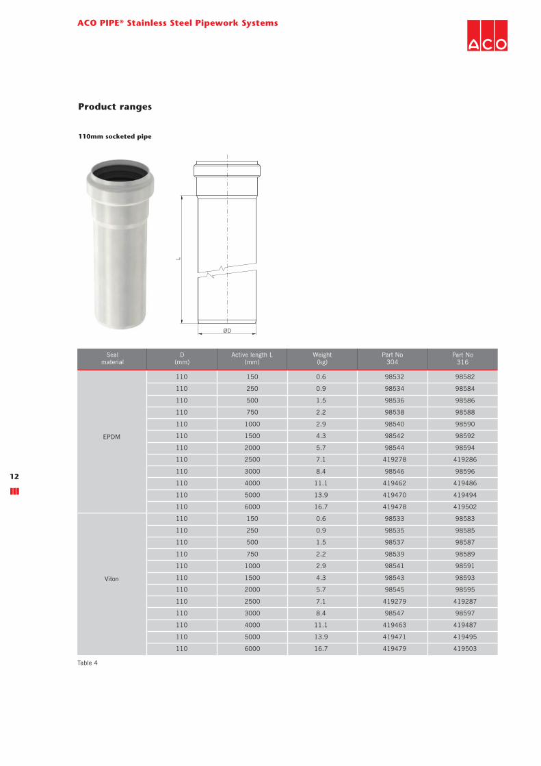
110mm socketed pipe
110 150 0.6 98532 98582
110 250 0.9 98534 98584
110 500 1.5 98536 98586
110 750 2.2 98538 98588
110 1000 2.9 98540 98590
110 1500 4.3 98542 98592
110 2000 5.7 98544 98594
110 2500 7.1 419278 419286
110 3000 8.4 98546 98596
110 4000 11.1 419462 419486
110 5000 13.9 419470 419494
110 6000 16.7 419478 419502
110 150 0.6 98533 98583
110 250 0.9 98535 98585
110 500 1.5 98537 98587
110 750 2.2 98539 98589
110 1000 2.9 98541 98591
110 1500 4.3 98543 98593
110 2000 5.7 98545 98595
110 2500 7.1 419279 419287
110 3000 8.4 98547 98597
110 4000 11.1 419463 419487
110 5000 13.9 419471 419495
110 6000 16.7 419479 419503
Sealmaterial
Part No316
D(mm)
Active length L(mm)
Part No304
Weight(kg)
EPDM
Viton
Product ranges
Table 4

ACO PIPE® family product ranges
13
Product ranges
Table 5
125mm socketed pipe
125 150 0.7 419692 419712
125 250 1.0 419694 419714
125 500 1.7 419696 419716
125 750 2.5 419698 419718
125 1000 3.3 419700 419720
125 1500 4.9 419702 419722
125 2000 6.5 419704 419724
125 2500 8.1 419708 419728
125 3000 9.6 419706 419726
125 6000 19.0 419710 419730
125 150 0.7 419693 419713
125 250 1.0 419695 419715
125 500 1.7 419697 419717
125 750 2.5 419699 419719
125 1000 3.3 419701 419721
125 1500 4.9 419703 419723
125 2000 6.5 419705 419725
125 2500 8.1 419709 419729
125 3000 9.6 419707 419727
125 6000 19.0 419711 419731
Sealmaterial
Part No316
D(mm)
Active length L(mm)
Part No304
Weight(kg)
EPDM
Viton
L
ØD

ACO PIPE® Stainless Steel Pipework Systems
14
160mm socketed pipe
160 150 1.1 98548 98598
160 250 1.6 98600 98650
160 500 2.9 98602 98652
160 750 4.1 98604 98654
160 1000 5.4 98606 98656
160 1500 7.9 98608 98658
160 2000 10.4 98610 98660
160 2500 12.9 419280 419288
160 3000 15.4 98612 98662
160 4000 20.4 419464 419488
160 5000 25.4 419472 419496
160 6000 30.4 419480 419504
160 150 1.1 98549 98599
160 250 1.6 98601 98651
160 500 2.9 98603 98653
160 750 4.1 98605 98655
160 1000 5.4 98607 98657
160 1500 7.9 98609 98659
160 2000 10.4 98611 98661
160 2500 12.9 419281 419289
160 3000 15.4 98613 98663
160 4000 20.4 419465 419489
160 5000 25.4 419473 419497
160 6000 30.4 419481 419505
Sealmaterial
Part No316
D(mm)
Active length L(mm)
Part No304
Weight(kg)
EPDM
Viton
L
ØD
Product ranges
Table 6

ACO PIPE® family product ranges
15
Product ranges
Table 7
L
ØD
200mm socketed pipe
200 500 4.5 419383 419384
200 1000 8.3 419387 419388
200 2000 15.8 419391 419392
200 3000 23.2 419395 419396
200 500 4.5 419385 419386
200 1000 8.3 419389 419390
200 2000 15.8 419393 419394
200 3000 23.2 419397 419398
Sealmaterial
Part No316
D(mm)
Active length L(mm)
Part No304
Weight(kg)
EPDM
Viton

L
ØD
ACO PIPE® Stainless Steel Pipework Systems
16
50mm double socketed pipe
50 250 0.4 419554 419594
50 500 0.7 419556 419596
50 750 1.1 419558 419598
50 1000 1.4 419560 419600
50 1500 2.0 419562 419602
50 2000 2.6 419564 419604
50 3000 3.9 419566 419606
50 250 0.4 419555 419595
50 500 0.7 419557 419597
50 750 1.1 419559 419599
50 1000 1.4 419561 419601
50 1500 2.0 419563 419603
50 2000 2.6 419565 419605
50 3000 3.9 419567 419607
Sealmaterial
Part No316
D(mm)
Active length L(mm)
Part No304
Weight(kg)
EPDM
Viton
Product ranges
Table 8

ACO PIPE® family product ranges
17
Product ranges
Table 9
L
ØD
75mm double socketed pipe
75 250 0.7 419568 419608
75 500 1.2 419570 419610
75 750 1.6 419572 419612
75 1000 2.1 419574 419614
75 1500 3.0 419576 419616
75 2000 4.0 419578 419618
75 3000 5.8 419580 419620
75 250 0.7 419569 419609
75 500 1.2 419571 419611
75 750 1.6 419573 419613
75 1000 2.1 419575 419615
75 1500 3.0 419577 419617
75 2000 4.0 419579 419619
75 3000 5.8 419581 419621
Sealmaterial
Part No316
D(mm)
Active length L(mm)
Part No304
Weight(kg)
EPDM
Viton

L
ØD
ACO PIPE® Stainless Steel Pipework Systems
18
110mm double socketed pipe
110 500 1.7 419582 419622
110 750 2.4 419584 419624
110 1000 3.0 419586 419626
110 1500 4.4 419588 419628
110 2000 5.7 419590 419630
110 3000 8.4 419592 419632
110 500 1.7 419583 419623
110 750 2.4 419585 419625
110 1000 3.0 419587 419627
110 1500 4.4 419589 419629
110 2000 5.7 419591 419631
110 3000 8.4 419593 419633
Sealmaterial
Part No316
D(mm)
Active length L(mm)
Part No304
Weight(kg)
EPDM
Viton
Product ranges
Table 10

ACO PIPE® family product ranges
19
Product ranges
Table 11
125mm double socketed pipe
125 500 1.7 419787 419799
125 750 2.5 419789 419801
125 1000 3.3 419791 419803
125 1500 4.9 419793 419805
125 2000 6.5 419795 419807
125 3000 9.6 419797 419809
125 500 1.7 419788 419800
125 750 2.5 419790 419802
125 1000 3.3 419792 419804
125 1500 4.9 419794 419806
125 2000 6.5 419796 419808
125 3000 9.6 419798 419810
Sealmaterial
Part No316
D(mm)
Active length L(mm)
Part No304
Weight(kg)
EPDM
Viton
L
ØD

L
ØD
ACO PIPE® Stainless Steel Pipework Systems
20
160 500 3.3 419634 419646
160 750 4.5 419636 419648
160 1000 5.8 419638 419650
160 1500 8.2 419640 419652
160 2000 10.7 419642 419654
160 3000 15.7 419644 419656
160 500 3.3 419635 419647
160 750 4.5 419637 419649
160 1000 5.8 419639 419651
160 1500 8.2 419641 419653
160 2000 10.7 419643 419655
160 3000 15.7 419645 419657
Sealmaterial
Part No316
D(mm)
Active length L(mm)
Part No304
Weight(kg)
EPDM
Viton
160mm double socketed pipe
Product ranges
Table 12

ACO PIPE® family product ranges
21
Product ranges
Table 13
L
ØD
200mm double socketed pipe
200 500 5.0 419658 419659
200 1000 8.6 419662 419663
200 2000 15.9 419666 419667
200 3000 23.1 419670 419671
200 500 5.0 419660 419661
200 1000 8.6 419664 419665
200 2000 15.9 419668 419669
200 3000 23.1 419672 419673
Sealmaterial
Part No316
D(mm)
Active length L(mm)
Part No304
Weight(kg)
EPDM
Viton

ACO PIPE® Stainless Steel Pipework Systems
22
50 86 40 0.2 98700 98750
75 107 53 0.4 98702 98752
110 134 67 0.7 98704 98754
125 161 93 0.8 419732 419734
160 181 105 1.7 98706 98756
200 215 129 3.9 419411 419413
50 86 40 0.2 98701 98751
75 107 53 0.4 98703 98753
110 134 67 0.7 98705 98755
125 161 93 0.8 419733 419735
160 181 105 1.7 98707 98757
200 215 129 3.9 419412 419414
Sealmaterial
Part No316
Part No304
D(mm)
a(mm)
Weight(kg)
b(mm)
EPDM
Viton
50 62 24 0.2 98708 98758
75 76 32 0.3 98710 98760
110 93 42 0.5 98712 98762
125 110 50 0.6 419736 419738
160 131 55 1.3 98714 98764
200 152 60 2.7 419407 419409
50 62 24 0.2 98709 98759
75 76 32 0.3 98711 98761
110 93 42 0.5 98713 98763
125 110 50 0.6 419737 419739
160 131 55 1.3 98715 98765
200 152 60 2.7 419408 419410
Sealmaterial
Part No316
Part No304
D(mm)
a(mm)
Weight(kg)
b(mm)
EPDM
Viton
b
a
87.5°
ØD
b
a
87.5°
ØD
b
a
45°
ØD
b
a
45°
ØD
87.5° bend
45° bend
Product ranges
Table 14
Table 15
Shape valid for DN 50,
75, 110 and 160.
Shape valid for DN 125
and 200.
Shape valid for
DN 125 and 200.
Shape valid for DN 50,
75, 110 and 160.

ACO PIPE® family product ranges
23
Product ranges
Table 16
Table 17
30° bend
50 57 16 0.2 98716 98766
75 71 21 0.3 98718 98768
110 85 27 0.5 98720 98770
125 98 28 0.6 419740 419742
160 110 40 1.2 98722 98772
200 137 45 2.3 419403 419405
50 57 16 0.2 98717 98767
75 71 21 0.3 98719 98769
110 85 27 0.5 98721 98771
125 98 28 0.6 419741 419743
160 110 40 1.2 98723 98773
200 137 45 2.3 419404 419406
Sealmaterial
Part No316
Part No304
D(mm)
a(mm)
Weight(kg)
b(mm)
EPDM
Viton
50 54 12 0.1 98724 98774
75 66 16 0.3 98726 98776
110 78 15 0.4 98728 98778
125 84 19 0.5 419744 419746
160 99 29 1.0 98730 98780
200 123 31 1.9 419399 419401
50 54 12 0.1 98725 98775
75 66 16 0.3 98727 98777
110 78 15 0.4 98729 98779
125 84 19 0.5 419745 419747
160 99 29 1.0 98731 98781
200 123 31 1.9 419400 419402
Sealmaterial
Part No316
Part No304
D(mm)
a(mm)
Weight(kg)
b(mm)
EPDM
Viton
b
a
30°
ØD
ba
ØD
15°
15° bend

ACO PIPE® Stainless Steel Pipework Systems
24
87.5° long bend
1 x 92.5º tall bend
Sealmaterial
D(mm)
a(mm)
b(mm)
c(mm)
e(mm)
f(mm)
Weight(kg)
Part No304
Part No316
EPDM
Viton
87.5°
e
ØDb
f
c
a
50 123 71 50 75 25 0.3 419146 419000
75 146 87 50 88 32 0.5 419148 419002
110 175 103 250 103 39 1.4 419150 419004
160 222 126 250 183 92 2.2 419152 419144
50 123 71 50 75 25 0.3 419147 419001
75 146 87 50 88 32 0.5 419149 419003
110 175 103 250 103 39 1.4 419151 419005
160 222 126 250 183 92 2.2 419153 419145
Product ranges
Table 18
Table 19
110 2.0 417056 417057
160 3.7 417058 417059
D(mm)
Weight(kg)
Part No304
Part No316
500
ØD
200
92.5°

ACO PIPE® family product ranges
25
Product ranges
Table 20
Table 21
110 309 478 2.4 417060 417061
160 319 498 4.4 417062 417063
F(mm)
Weight(kg)
D(mm)
C(mm)
Part No304
Part No316
2 x 46º tall bend
87.5° single branch
50 106 71 0.3 98732 98782
75 139 90 0.5 98734 98784
110 183 117 0.8 98736 98786
125 220 135 0.9 419748 419750
160 288 184 2.3 98738 98788
200 333 206 4.5 419419 419421
50 106 71 0.3 98733 98783
75 139 90 0.5 98735 98785
110 183 117 0.8 98737 98787
125 220 135 0.9 419749 419751
160 288 184 2.3 98739 98789
200 333 206 4.5 419420 419422
Sealmaterial
Part No316
Part No304
D(mm)
a(mm)
Weight(kg)
b(mm)
EPDM
Viton
a
b
ØD
87.5°
300 150
600
ØD
C
F
2 x 46°
a
b
c
ØD
45°
ACO PIPE® Stainless Steel Pipework Systems
26
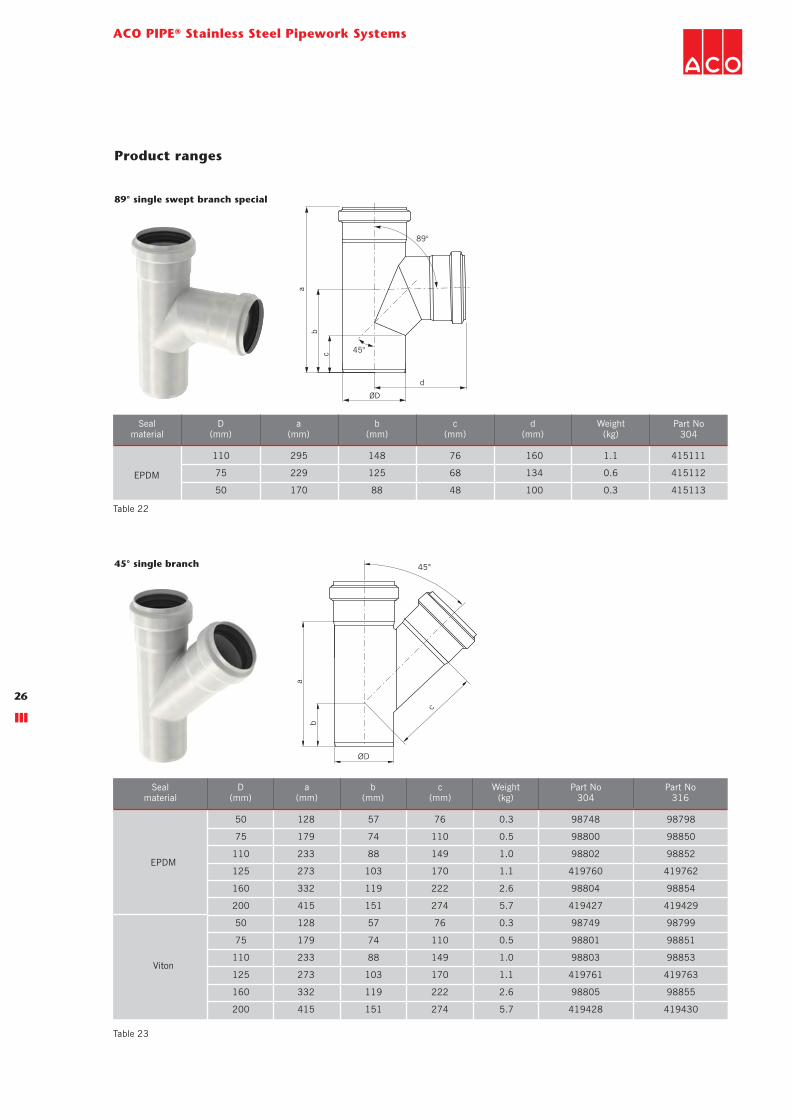
45° single branch
Sealmaterial
D(mm)
a(mm)
b(mm)
c(mm)
Weight(kg)
Part No304
Part No316
EPDM
Viton
50 128 57 76 0.3 98748 98798
75 179 74 110 0.5 98800 98850
110 233 88 149 1.0 98802 98852
125 273 103 170 1.1 419760 419762
160 332 119 222 2.6 98804 98854
200 415 151 274 5.7 419427 419429
50 128 57 76 0.3 98749 98799
75 179 74 110 0.5 98801 98851
110 233 88 149 1.0 98803 98853
125 273 103 170 1.1 419761 419763
160 332 119 222 2.6 98805 98855
200 415 151 274 5.7 419428 419430
Product ranges
Table 23
Table 22
89° single swept branch special
110 295 148 76 160 1.1 415111
75 229 125 68 134 0.6 415112
50 170 88 48 100 0.3 415113
a(mm)
Part No304
b(mm)
Sealmaterial
D(mm)
c(mm)
Weight(kg)
d(mm)
EPDM
b
d
a
c
ØD
89°
45°

ACO PIPE® family product ranges
27
Product ranges
Table 24
Table 25
a
b
ØD
87.5°87.5° double branch
89° double swept branch special
50 106 71 0.3 98740 98790
75 139 90 0.6 98742 98792
110 183 117 0.9 98744 98794
160 288 184 2.7 98746 98796
50 106 71 0.3 98741 98791
75 139 90 0.6 98743 98793
110 183 117 0.9 98745 98795
160 288 184 2.7 98747 98797
Sealmaterial
Part No316
Part No304
D(mm)
a(mm)
Weight(kg)
b(mm)
EPDM
Viton
b
d
a
c
ØD
89°
45°
110 295 148 76 160 1.4 415108
75 229 125 68 134 0.8 415109
50 170 88 48 100 0.4 415110
a(mm)
Part No304
b(mm)
Sealmaterial
D(mm)
c(mm)
Weight(kg)
d(mm)
EPDM

ACO PIPE® Stainless Steel Pipework Systems
28
90°87.5°
a
b
ØD
D
87.5° corner branch
50 106 71 0.4 419162 419210
75 139 90 0.7 419164 419212
110 183 117 1.1 419166 419214
125 220 135 1.6 417020 417021
160 288 184 2.9 419168 419216
50 106 71 0.4 419163 419211
75 139 90 0.7 419165 419213
110 183 117 1.1 419167 419215
125 220 135 1.6 417054 417055
160 288 184 2.9 419169 419217
Sealmaterial
Part No316
Part No304
D(mm)
a(mm)
Weight(kg)
b(mm)
EPDM
Viton
a
b
c
ØD
45° 45°45° double branch
Sealmaterial
D(mm)
a(mm)
b(mm)
c(mm)
Weight(kg)
Part No304
Part No316
50 128 57 76 0.4 98806 98856
75 179 74 110 0.7 98808 98858
110 233 88 149 1.2 98810 98860
160 332 184 222 3.5 98812 98862
50 128 57 76 0.4 98807 98857
75 179 74 110 0.7 98809 98859
110 233 88 149 1.2 98811 98861
160 332 184 222 3.5 98813 98863
EPDM
Viton
Product ranges
Table 26
Table 27

a
b
ØD
2
ØD1
87.5°
ACO PIPE® family product ranges
29
Product ranges
Table 28
Table 29
87.5° single branch reduction
89° single swept branch reduction special
Sealmaterial
D1(mm)
D2(mm)
a(mm)
b(mm)
Weight(kg)
Part No304
Part No316
75 50 139 90 0.3 98928 98930
110 50 183 117 0.5 98932 98934
110 75 183 117 0.8 98936 98938
125 75 187 110 0.9 419752 419754
125 110 205 127 0.9 419756 419758
160 110 288 184 2.3 400691 400693
200 160 293 186 3.7 419415 419417
75 50 139 90 0.3 98929 98931
110 50 183 117 0.5 98933 98935
110 75 183 117 0.8 98937 98939
125 75 187 110 0.9 419753 419755
125 110 205 127 0.9 419757 419759
160 110 288 184 2.3 400692 400694
200 160 293 186 3.7 419416 419418
EPDM
Viton
ba
ØD1d
c
ØD
2
89°
45°
110 50 295 148 104 135 0.9 415106
110 75 295 148 81 143 1.0 415107
D2(mm)
Weight(kg)
Part No304
a(mm)
Sealmaterial
D1(mm)
b(mm)
d(mm)
c(mm)
EPDM

ACO PIPE® Stainless Steel Pipework Systems
30
ØD1
ØD2
45°
a
b
c
45° single branch reduction
Sealmaterial
D1(mm)
Part No304
Part No316
D2(mm)
a(mm)
b(mm)
c(mm)
Weight(kg)
EPDM
Viton
75 50 144 56 94 0.3 400661 400663
110 50 147 42 119 0.5 400665 400667
110 75 182 60 135 1.0 400669 400671
125 75 200 65 141 1.1 419764 419766
125 110 250 90 160 1.1 419768 419770
160 110 332 119 191 2.6 400699 400701
200 160 359 123 250 4.7 419423 419425
75 50 144 56 94 0.3 400662 400664
110 50 147 42 119 0.5 400666 400668
110 75 182 60 135 1.0 400670 400672
125 75 200 65 141 1.1 419765 419767
125 110 250 90 160 1.1 419769 419771
160 110 332 119 191 2.6 400700 400702
200 160 359 123 250 4.7 419424 419426
Product ranges
Table 30

ACO PIPE® family product ranges
31
Product ranges
Table 31
Table 32
Sealmaterial
D(mm)
D2(mm)
a(mm)
b(mm)
Weight(kg)
Part No304
Part No316
75 50 139 90 0.3 98940 98942
110 50 183 117 0.6 98944 98946
110 75 183 117 0.9 98900 98902
160 110 288 184 2.7 400695 400697
75 50 139 90 0.3 98941 98943
110 50 183 117 0.6 98945 98947
110 75 183 117 0.9 98901 98903
160 110 288 184 2.7 400696 400698
EPDM
Viton
a
b
ØD1
ØD2
87,5°
87.5° double branch reduction
89° double swept branch reduction special
110 75 295 148 81 143 1.1 415104
110 50 295 148 104 135 1.0 415105
D2(mm)
Weight(kg)
Part No304
a(mm)
Sealmaterial
D1(mm)
b(mm)
d(mm)
c(mm)
EPDM
b
c
a
ØD1
ØD
2
89°
d
45°
ACO PIPE® Stainless Steel Pipework Systems
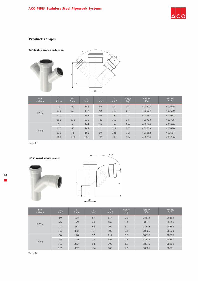
32
a
ØD
b
c
87.5°
87.5° swept single branch
Sealmaterial
D(mm)
a(mm)
b(mm)
c(mm)
Weight(kg)
Part No304
Part No316
50 128 57 117 0.3 98814 98864
75 179 74 157 0.6 98816 98866
110 233 88 209 1.1 98818 98868
160 332 184 302 2.8 98820 98870
50 128 57 117 0.3 98815 98865
75 179 74 157 0.6 98817 98867
110 233 88 209 1.1 98819 98869
160 332 184 302 2.8 98821 98871
EPDM
Viton
Product ranges
Table 33
Table 34
ØD1
ØD2
a
b
c
45°45°45° double branch reduction
Sealmaterial
D1(mm)
Part No304
Part No316
D2(mm)
a(mm)
b(mm)
c(mm)
Weight(kg)
EPDM
Viton
75 50 144 56 94 0.4 400673 400675
110 50 147 42 119 0.7 400677 400679
110 75 182 60 135 1.2 400681 400683
160 110 332 119 190 3.5 400703 400705
75 50 144 56 94 0.4 400674 400676
110 50 147 42 119 0.7 400678 400680
110 75 182 60 135 1.2 400682 400684
160 110 332 119 190 3.5 400704 400706

a
b
c
ØD
2.5°
ACO PIPE® family product ranges
33
“P” trap
Sealmaterial
D(mm)
a(mm)
b(mm)
c(mm)
Weight(kg)
Part No304
Part No316
50 68 187 149 0.5 98822 98872
75 94 232 193 0.7 98824 98874
110 132 300 254 1.3 98826 98876
160 190 403 347 3.3 98828 98878
50 68 187 149 0.5 98823 98873
75 94 232 193 0.7 98825 98875
110 132 300 254 1.3 98827 98877
160 190 403 347 3.3 98829 98879
EPDM
Viton
Product ranges
Table 35

ACO PIPE® Stainless Steel Pipework Systems
34
a
ØD
Straight coupling
50 54 0.1 98920 98970
75 75 0.2 98922 98972
110 84 0.4 98924 98974
125 140 0.4 419813 419815
160 110 0.8 98926 98976
200 136 1.8 419431 419433
50 54 0.1 98921 98971
75 75 0.2 98923 98973
110 84 0.4 98925 98975
125 140 0.4 419814 419816
160 110 0.8 98927 98977
200 136 1.8 419432 419434
Sealmaterial
Part No316
D(mm)
a(mm)
Part No304
Weight(kg)
EPDM
Viton
a
ØD
Repair coupling
50 44 0.1 98830 98880
75 46 0.2 98832 98882
110 52 0.3 98834 98884
125 70 0.3 419772 419774
160 76 0.7 98836 98886
200 100 1.5 419435 419437
50 44 0.1 98831 98881
75 46 0.2 98833 98883
110 52 0.3 98835 98885
125 70 0.3 419773 419775
160 76 0.7 98837 98887
200 100 1.5 419436 419438
Sealmaterial
Part No316
D(mm)
a(mm)
Part No304
Weight(kg)
EPDM
Viton
Note: Repair couplings are used to aid a convenient repair to a damaged in-situ pipe. Unlike the standard straight coupling, there is no central
registration to limit the insertion depth of the pipe. The repair coupling slides completely over a pipe joint and simply re-positioned to bridge the
required pipe joint. Installation tip: Mark the final position of the repair coupling on the installed pipe system to ensure the coupling seals are
positioned symmetrically about the pipe joint.
Product ranges
Table 36
Table 37
ACO PIPE® family product ranges
35
a
b
ØD
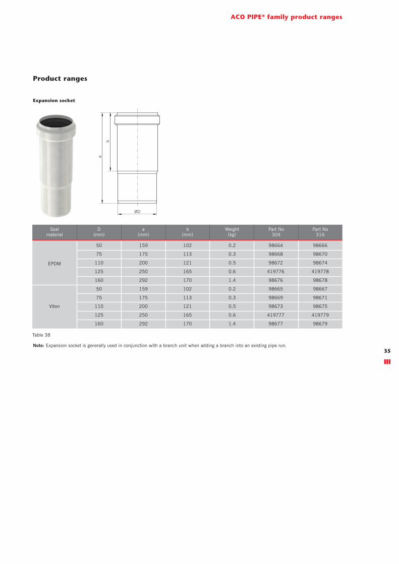
Product ranges
Expansion socket
50 159 102 0.2 98664 98666
75 175 113 0.3 98668 98670
110 200 121 0.5 98672 98674
125 250 165 0.6 419776 419778
160 292 170 1.4 98676 98678
50 159 102 0.2 98665 98667
75 175 113 0.3 98669 98671
110 200 121 0.5 98673 98675
125 250 165 0.6 419777 419779
160 292 170 1.4 98677 98679
Sealmaterial
Part No316
Part No304
D(mm)
a(mm)
Weight(kg)
b(mm)
EPDM
Viton
Note: Expansion socket is generally used in conjunction with a branch unit when adding a branch into an existing pipe run.
Table 38

ACO PIPE® Stainless Steel Pipework Systems
36
50 75 88 7 0.3 98892
50 110 103 25 0.4 98978
75 110 116 15 0.5 98894
110 160 136 22 1.1 98896
50 75 88 7 0.3 98893
50 110 103 25 0.4 98979
75 110 116 15 0.5 98895
110 160 136 22 1.1 98897
Sealmaterial
Part No316
Weight(kg)
D1(mm)
D2(mm)
b(mm)
a(mm)
EPDM
Viton
110 125 107 0 0.6 419780
125 160 113 0 1.2 419811
160 200 170 0 1.8 419441
110 125 107 0 0.6 419781
125 160 113 0 1.2 419812
160 200 170 0 1.8 419442
Sealmaterial
Part No316
Weight(kg)
D1(mm)
D2(mm)
b(mm)
a(mm)
EPDM
Viton
Product ranges
ØD1
b aØD2
ØD1
a
ØD2
Eccentric increaser coupling
Concentric increaser coupling
Table 39
Table 40

ACO PIPE® family product ranges
37
ØD1
ØD2
a
a
ØD2
ØD1
ØD2
ØD1
a
Increaser connector
Product ranges
NBR 32 50 90 0.2 419373
NBR 40 50 90 0.2 419374
Sealmaterial
Part No316
D1(mm)
D2(mm)
Weight(kg)
a(mm)
Connector with internal screw thread and spigot
50 Rp 1¼" 72 0.2 98956
50 Rp 1½" 75 0.3 98957
50 Rp 2" 80 0.3 98958
D1(mm) D2 a
(mm)Weight
(kg)Part No
316
Connector with external screw thread and spigot
50 Rp 1¼" 100 0.2 419330
50 Rp 1½" 100 0.3 419331
50 Rp 2" 100 0.3 419332
D1(mm) D2 a
(mm)Weight
(kg)Part No
316
Table 43
Table 41
Table 42

ACO PIPE® Stainless Steel Pipework Systems
38
ØD1
ØD2
a
Connector with socket and internal screw thread
50 R 1¼" 58 0.2 419333
50 R 1½" 58 0.3 419335
50 R 2" 58 0.3 419337
50 R 1¼" 58 0.2 419334
50 R 1½" 58 0.3 419336
50 R 2" 58 0.3 419338
Sealmaterial
Part No316
D1(mm) D2 Weight
(kg)a
(mm)
EPDM
Viton
ØD1
ØD2
a
Connector with socket and external screw thread
50 R 1¼" 58 0.2 419250
50 R 1½" 58 0.3 419252
50 R 2" 58 0.3 419254
50 R 1¼" 58 0.2 419251
50 R 1½" 58 0.3 419253
50 R 2" 58 0.3 419255
Sealmaterial
Part No316
D1(mm) D2 Weight
(kg)a
(mm)
EPDM
Viton
Product ranges
Table 44
Table 45

ACO PIPE® family product ranges
39
ØD1
ØD5
a
ØD2ØD3ØD4
Connector with socket and flange
Sealmaterial
D1(mm)
Weight(kg)
Part No316
D2(mm)
D3(mm)
D4(mm)
n × D5(mm)
a(mm)
EPDM
Viton
50 DN 40 110 150 4 × 18 100 2.3 419256
50 DN 50 125 165 4 × 18 100 2.7 419258
75 DN 65 145 185 4 × 18 100 3.4 419260
110 DN 100 180 220 8 × 18 100 4.9 419262
200 DN 200 295 340 12 × 22 102 12.0 419514
50 DN 40 110 150 4 × 18 100 2.3 419257
50 DN 50 125 165 4 × 18 100 2.7 419259
75 DN 65 145 185 4 × 18 100 3.4 419261
110 DN 100 180 220 8 × 18 100 4.9 419263
200 DN 200 295 340 12 × 22 102 12.0 419515
Product ranges
Note: Flange PN16 to DIN 2633. Flanges to PN6 and PN10 available on request.
Connector with spigot and flange
50 DN 40 110 150 4 × 18 192 2.3 419264
50 DN 50 125 165 4 × 18 192 2.7 419265
75 DN 65 145 185 4 × 18 245 3.4 419266
110 DN 100 180 220 8 × 18 259 4.9 419267
160 DN 150 240 285 8 × 22 200 8.5 419540
200 DN 200 295 240 12 × 22 240 12.3 419541
D1(mm)
D2(mm)
D3(mm)
D4(mm)
n × D5(mm)
a(mm)
Weight(kg)
Part No316
Note: Flange PN16 to DIN 2633. Flanges to PN6 and PN10 available on request.
ØD1
a
ØD2ØD3ØD4
ØD5
Table 46
Table 47
ACO PIPE® Stainless Steel Pipework Systems
40
a
b
ØD
l
ØD
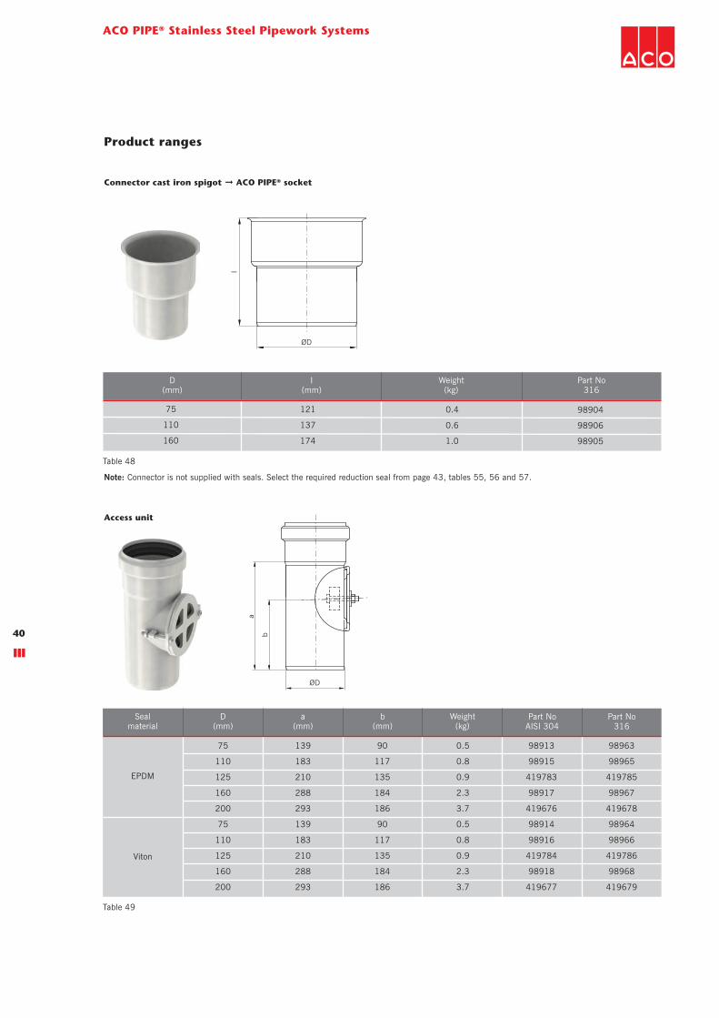
Connector cast iron spigot ➞ ACO PIPE® socket
75 121 0.4 98904
110 137 0.6 98906
160 174 1.0 98905
D(mm)
I(mm)
Weight(kg)
Part No316
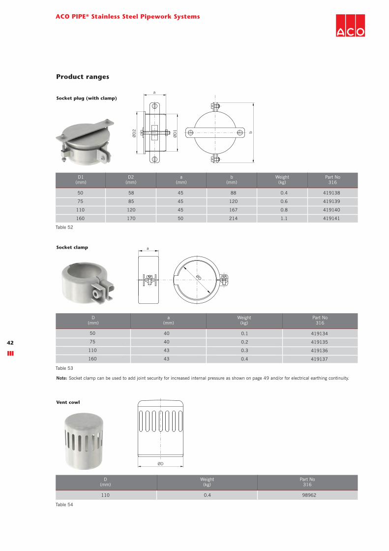
Access unit
75 139 90 0.5 98913 98963
110 183 117 0.8 98915 98965
125 210 135 0.9 419783 419785
160 288 184 2.3 98917 98967
200 293 186 3.7 419676 419678
75 139 90 0.5 98914 98964
110 183 117 0.8 98916 98966
125 210 135 0.9 419784 419786
160 288 184 2.3 98918 98968
200 293 186 3.7 419677 419679
Sealmaterial
Part No316
Part NoAISI 304
D(mm)
a(mm)
Weight(kg)
b(mm)
EPDM
Viton
Product ranges
Note: Connector is not supplied with seals. Select the required reduction seal from page 43, tables 55, 56 and 57.
Table 48
Table 49

ACO PIPE® family product ranges
41
Product ranges
ØD1
l
ØD2
Rat-stop pipe
EPDM 110 250 864 3.8 419268 419270
Viton 110 250 864 3.8 419269 419271
Sealmaterial
Part No316
Part No304
D1(mm)
D2(mm)
Weight(kg)
l(mm)
ØD2
ØD1
a
Socket plug (no clamp)
50 58 45 0.1 98888
75 85 45 0.3 98889
110 120 45 0.5 98890
125 135 50 0.6 419782
160 170 50 0.5 98891
200 210 50 1.0 98994
D1(mm)
D2(mm)
a(mm)
Weight(kg)
Part No316
Table 50
Table 51
ACO PIPE® Stainless Steel Pipework Systems
42
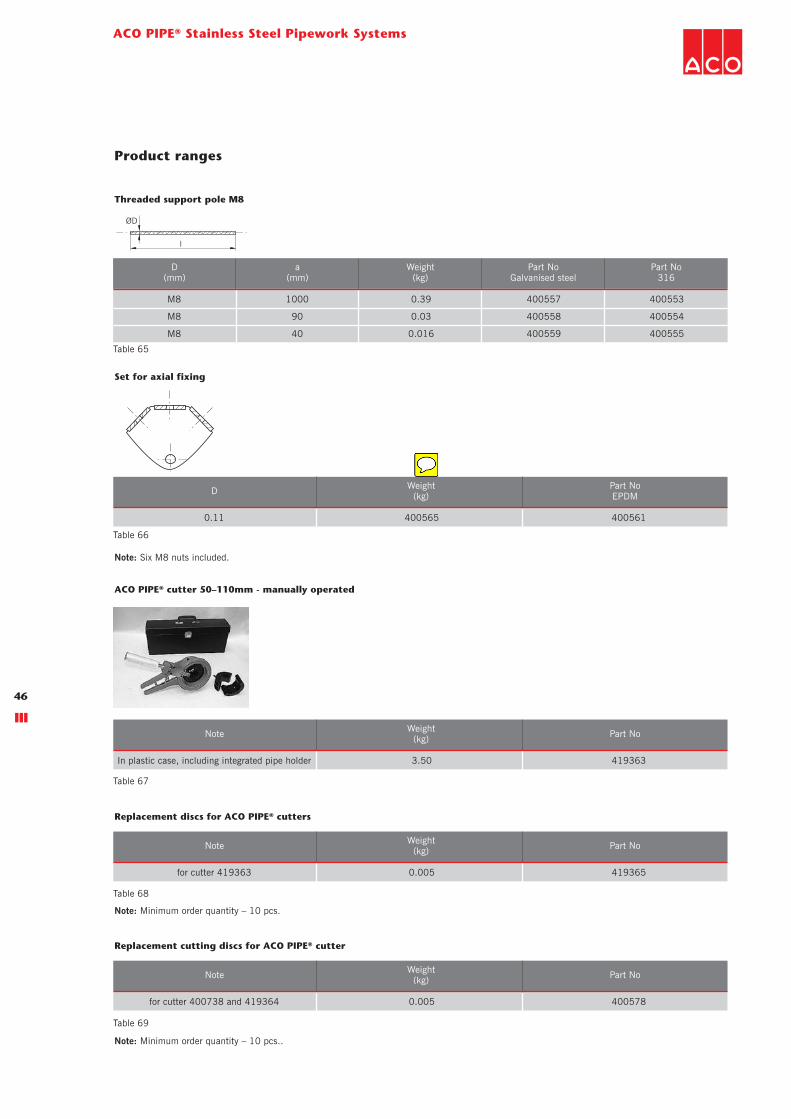
Socket clamp
Vent cowl
50 40 0.1 419134
75 40 0.2 419135
110 43 0.3 419136
160 43 0.4 419137
D(mm)
a(mm)
Weight(kg)
Part No316
ØD
a
ØD
110 0.4 98962
D(mm)
Weight(kg)
Part No316
Product ranges
ØD
2
ØD
1 b
a
Socket plug (with clamp)
50 58 45 88 0.4 419138
75 85 45 120 0.6 419139
110 120 45 167 0.8 419140
160 170 50 214 1.1 419141
D1(mm)
Part No316
D2(mm)
a(mm)
Weight(kg)
b(mm)
Table 52
Table 53
Table 54
Note: Socket clamp can be used to add joint security for increased internal pressure as shown on page 49 and/or for electrical earthing continuity.

ACO PIPE® family product ranges
43
Prefabricated manifolds
Reduction sealing cast Iron spigot ➞ ACO PIPE® socket
75 / DN 70 0.06 400580
110 / DN 100 0.10 400581
160 / DN 150 0.14 400582
Cast iron spigot(mm)
Weight(kg)
Part NoEPDM
75 / DN 70 0.05 400586
110 / DN 100 0.08 400587
160 / DN 150 0.12 400588
Cast iron spigot(mm)
Weight(kg)
Part NoEPDM
Reduction sealing set for cast iron
75 / DN 70 0.11 419370
110 / DN 100 0.18 419371
160 / DN 150 0.26 419372
Cast iron spigot(mm)
Weight(kg)
Part NoEPDM
Set of reduction sealings cast iron spigot ➞ ACO PIPE® socket and ACO PIPE® spigot ➞ cast iron
Product ranges
Reduction sealing ACO PIPE® spigot ➞ cast iron socket
Table 55
Table 56
Table 57
ACO Building Drainage can design and manufacture bespoke manifolds to suit any application.
Please contact our Bespoke Department on 01462 816666 for further information.

ACO PIPE® Stainless Steel Pipework Systems
44
Socket clamp
50 0.01 98400 98404
75 0.02 98401 98405
110 0.05 98402 98406
125 0.06 419453 419454
160 0.08 98403 98407
200 0.10 98433 98437
D(mm)
Weight(kg)
Part NoEPDM
Part NoViton
ACO Universal lubricant
0.15 E80350000
Weight(kg) Part No
ACO Universal lubricant in bucket 1kg
1.00 E80350001
Weight(kg) Part No
8.4 70 0.05 400525 400521
D(mm)
a(mm)
Weight(kg)
Part NoGalvanised steel
Part No316
a
ØD
Product ranges
Note: Spare ACO PIPE® seals in EPDM and Viton® grades are available for all pipe sizes. All seals incorporate the unique ACO PIPE® double lip seal
arrangement for increased reliability and security. Both seal materials are mechanically interchangeable thereby facilitating easy on-site upgrade from
EPDM to Viton®, for example. For seal installation instructions, refer to the Appendices. To aid identification, the seals are colour coded as follows:
EPDM seals are BLACK. Viton® seals are GREEN.
Table 58
Table 59
Table 60
Table 61
Fixing plate

a
ACO PIPE® family product ranges
45
Support bracket with rubber infill
Support bracket with rubber infill and stirrup
50 56 0.18 400541 400537
75 80 0.28 400542 400538
110 116 0.41 400543 400539
160 166 0.48 400544 400540
D(mm)
a(mm)
Weight(kg)
Part NoGalvanised steel
Part No316
Product ranges
Table 63
a
Support bracket with rubber infill and key
50 120 0.16 400549 400545
75 133 0.26 400550 400546
110 150 0.38 400551 400547
160 175 0.44 400552 400548
D(mm)
a(mm)
Weight(kg)
Part NoGalvanised steel
Part No316
Table 64
50 0.14 400533 400529
75 0.23 400534 400530
110 0.33 400535 400531
125 0.36 419854 419855
160 0.39 400536 400532
200 0.44 419451 419675
D(mm)
Weight(kg)
Part NoGalvanised steel
Part No316
Table 62
ACO PIPE® Stainless Steel Pipework Systems
46
Set for axial fixing
0.11 400565 400561
D Weight(kg)
Part NoEPDM
Note: Six M8 nuts included.
ACO PIPE® cutter 50–110mm - manually operated
In plastic case, including integrated pipe holder 3.50 419363
Note Weight(kg) Part No
Replacement discs for ACO PIPE® cutters
for cutter 419363 0.005 419365
Note Weight(kg) Part No
Note: Minimum order quantity – 10 pcs.
Replacement cutting discs for ACO PIPE® cutter
for cutter 400738 and 419364 0.005 400578
Note Weight(kg) Part No
Note: Minimum order quantity – 10 pcs..
Product ranges
Table 66
Table 67
Table 68
Table 69
l
ØD
Threaded support pole M8
M8 1000 0.39 400557 400553
M8 90 0.03 400558 400554
M8 40 0.016 400559 400555
D(mm)
a(mm)
Weight(kg)
Part NoGalvanised steel
Part No316
Table 65

ACO PIPE® family product ranges
47
ACO PIPE® manual cutter
50–110 1.0 419364
110–160 2.0 400738
D(mm)
Weight(kg) Part No
Note: While purchasing ACO PIPE® manual cutter it is necessary to order ACO PIPE® holder for manual cutting.
ACO PIPE® holder for manual cutting
Pipe marking kit*
125 3.5 419857
160 4.0 400742
D(mm)
Weight(kg) Part No
Note: While ordering ACO PIPE® holder for manual cutting it is recommended to order ACO PIPE® cutter for manual cutting.
*Note: Pipe marking kit allows installer to conveniently and quickly mark pipes to ensure reliable visual insertion depth.
Product ranges
Table 72
Table 70
Table 71
Part No D(mm)
A(mm)
B(mm)
C(mm)
E(mm)
F(mm)
Weight(kg)
50 78 48 25 20 2 0.35
75 88 58 25 20 2 0.35
110 93 63 25 20 2 0.35
125 99 69 25 20 2 0.35
160 107 77 25 20 2 0.35
200 120 90 25 20 2 0.35
417064
A
E
60°
C
B
F

ACO PIPE® Stainless Steel Pipework Systems
48
Full bore flow rate tables for varying gradients
Flow rates and operating pressure
For rainwater/storm drainage applications
Flow rates based on Colebrook-White formula.
Roughness Coefficient ks = 0.6mm (calculations uses internal diameters for pipes).
The flow rates shown in the table 73 assume a free outlet from the pipe. For installations without a free outlet, the flow rate will be affected by the
downstream throttle.
For shallow gradients, the Colebrook-White formula underestimates flow rates (because when gradient tends towards zero %, velocity also tends to
zero). For level or nearly level installations (slope < 1 %), spatially varied flow tables should be used; refer to the table 75.
10.0 2.74 1.52 8.40 2.01 23.81 2.60 33.61 2.83 64.15 3.31 116.89 3.83
7.5 2.38 1.31 7.28 1.74 20.62 2.25 29.11 2.45 55.56 2.87 101.22 3.32
5.0 1.94 1.07 5.94 1.42 16.83 1.84 23.77 2.00 45.36 2.34 82.65 2.71
4.5 1.84 1.02 5.64 1.35 15.97 1.74 22.55 1.90 43.03 2.22 78.40 2.57
4.0 1.73 0.96 5.31 1.27 15.06 1.64 21.26 1.79 40.57 2.10 73.92 2.43
3.5 1.62 0.90 4.97 1.19 14.08 1.54 19.88 1.67 37.95 1.96 69.14 2.27
3.0 1.50 0.83 4.60 1.10 13.04 1.42 18.41 1.55 35.13 1.81 64.01 2.10
2.5 1.37 0.76 4.20 1.00 11.90 1.30 16.80 1.41 32.07 1.66 58.43 1.92
2.0 1.23 0.68 3.76 0.90 10.64 1.16 15.03 1.26 28.68 1.48 52.26 1.71
1.5 1.06 0.59 3.25 0.78 9.22 1.01 13.01 1.10 24.84 1.28 45.26 1.48
1.0 0.87 0.48 2.66 0.63 7.53 0.82 10.63 0.89 20.28 1.05 36.95 1.21
Gradient(%)
Flowrate
Q (l/s)
Velocityv (m/s)
Pipe Ø 50mm
Flowrate
Q (l/s)
Velocityv (m/s)
Pipe Ø 75mm
Flowrate
Q (l/s)
Velocityv (m/s)
Pipe Ø 110mm
Flowrate
Q (l/s)
Velocityv (m/s)
Pipe Ø 125mm
Flowrate
Q (l/s)
Velocityv (m/s)
Pipe Ø 160mm
Flowrate
Q (l/s)
Velocityv (m/s)
Pipe Ø 200mm
For soil/foul water drainage applications
Flow rates based on Colebrook-White formula.
Roughness Coefficient ks = 0.6mm (calculations uses internal diameters for pipes).
The flow rates shown in the table 74 assume a free outlet from the pipe. For installations without a free outlet, the flow rate will be affected by the
downstream throttle.
For shallow gradients, the Colebrook-White formula underestimates flow rates (because when gradient tends towards zero %, velocity also tends to
zero). For level or nearly level installations (slope < 1 %), spatially varied flow tables should be used; refer to the table 75.
10.0 2.30 1.27 7.14 1.71 20.45 2.23 28.97 2.44 55.61 2.87 101.81 3.34
7.5 1.99 1.10 6.19 1.48 17.71 1.93 25.09 2.11 48.16 2.49 88.17 2.89
5.0 1.63 0.90 5.05 1.21 14.46 1.58 20.49 1.72 39.32 2.03 71.99 2.36
4.5 1.54 0.85 4.79 1.14 13.72 1.50 19.43 1.64 37.30 1.93 68.30 2.24
4.0 1.46 0.80 4.52 1.08 12.94 1.41 18.32 1.54 35.17 1.82 64.39 2.11
3.5 1.36 0.75 4.23 1.01 12.10 1.32 17.14 1.44 32.90 1.70 60.23 1.98
3.0 1.26 0.70 3.91 0.93 11.20 1.22 15.87 1.34 30.46 1.57 55.76 1.83
2.5 1.15 0.64 3.57 0.85 10.23 1.12 14.49 1.22 27.80 1.44 50.90 1.67
2.0 1.03 0.57 3.19 0.76 9.15 1.00 12.96 1.09 24.87 1.28 45.53 1.49
1.5 0.89 0.49 2.77 0.66 7.92 0.86 11.22 0.94 21.53 1.11 39.43 1.29
1.0 0.73 0.40 2.26 0.54 6.47 0.71 9.16 0.77 17.58 0.91 32.19 1.06
Gradient(%)
Flowrate
Q (l/s)
Velocityv (m/s)
Pipe Ø 50mm
Flowrate
Q (l/s)
Velocityv (m/s)
Pipe Ø 75mm
Flowrate
Q (l/s)
Velocityv (m/s)
Pipe Ø 110mm
Flowrate
Q (l/s)
Velocityv (m/s)
Pipe Ø 125mm
Flowrate
Q (l/s)
Velocityv (m/s)
Pipe Ø 160mm
Flowrate
Q (l/s)
Velocityv (m/s)
Pipe Ø 200mm
Table 73
Table 74

Flow rates and operating pressure
49
Flow rates based on spatially-varied flow formula for steady non-uniform flow
Strickler Coefficient = 90
For any further assistance call the ACO Building Drainage helpline on 01462 816666.
Pipe diameter (mm) Length (m) 0.0% Flow rateQ (l/s)
0.25% Flow rateQ (l/s)
0.5% Flow rateQ (l/s)
0.75% Flow rateQ (l/s)
Gradient
Operating pressure
The ACO PIPE® socketed stainless steel pipe
systems are fitted with a unique, double lip
seal manufactured from either EPDM or
Viton®. The double lip seal arrangement
provides added security for the ultimate in
long term reliability.
The ACO PIPE® socketed stainless steel pipe
systems are tested and approved for operating
pressures in all gravity, syphonic and vacuum
systems.
ACO PIPE® push fit stainless steel pipe
systems are designed for maximum working
pressure up to 0.5 bar. In cases where higher
pressure may occur joints need to be locked
with socket clamps.
50 0.5 2.0
75 0.5 2.0
110 0.5 2.0
160 0.5 1.0
Pipediameter
(mm) Without socketclamp
With socketclamp
50 5 0.40 0.57 0.75 0.92
50 10 0.30 0.54 0.75 0.92
50 15 0.26 0.53 0.75 0.92
50 20 0.23 0.53 0.75 0.92
75 5 1.45 1.75 2.40 2.90
75 10 1.10 1.72 2.35 2.90
75 15 0.95 1.70 2.35 2.90
75 20 0.85 1.70 2.35 2.90
110 5 4.50 5.55 6.75 8.15
110 10 3.60 5.05 6.60 8.15
110 15 3.20 4.90 6.50 8.15
110 20 2.80 4.80 6.50 8.15
125 5 6.45 7.90 9.60 11.45
125 10 5.20 7.25 9.50 11.45
125 15 4.55 7.00 9.50 11.45
125 20 4.10 6.85 9.50 11.45
160 5 13.00 15.40 18.60 21.20
160 10 10.90 14.30 18.50 21.20
160 15 9.50 13.80 18.40 21.20
160 20 8.50 13.50 18.30 21.20
200 5 24.80 29.00 34.20 38.70
200 10 20.80 26.70 33.80 38.40
200 15 18.60 25.70 33.70 38.40
200 20 17.00 25.00 33.60 38.40
Max. operating pressure (bar)
Full bore flow rate tables for varying gradients
Flow rates and operating pressure
Table 75
Table 76

ACO PIPE® Stainless Steel Pipework Systems
50
Installation guide
Generally
The following standards will assist designers
select the correct size of pipe system for a
particular application: BS EN 12056:
gravity drainage systems inside buildings.
BS EN 752: drain and sewer systems outside
buildings. Installation should be in accordance
with the manufacturer’s recommendations but
also BS EN 12056–2, BS EN 12056–3 and
BS EN 752.
Pipe cutting
If it is necessary to adapt or shorten pipe
lengths then whatever tools are used, the cut
must be square, clean, ready chamfered and
free from burrs. Suitable cutters and whole
cutter sets are available from ACO
(see page 46).
Pipe weights
Engineers should be aware of minimum
and maximum weights when designing
vertical stack and horizontal pipe run
systems. Generally, when the pipe is
completely full of water, then the vertical
deflection of the pipe between brackets should
not exceed 1.5mm. The discretion of the
installer should be applied in each instance to
ensure that the pipe is adequately supported.
As a guide, use the table below for bracket
spacing on horizontal pipes.
50 2.0
75 2.3
110 2.5
125 2.5
160 2.5
200 2.5
Pipe Ø (mm) Vertical BracketSpacing (m)
Horizontal pipe runs
Horizontal pipework should be supported with
at least two brackets per 3 metre pipe length.
Brackets should be within 300mm of the pipe
joints and approximately at the midpoint of the
pipe length, but not more than 2 metres from
the next bracket. Additional brackets should be
used at changes of direction and at junction
points immediately downstream of the fitting.
Where long pipe runs occur i.e. greater than
15 metres, a fixing arm should be attached to
the bracket to prevent pendulum movement
within the system.
Vertical pipe stacks
When designing a rainwater or soil and waste
system, pipework must be supported and
using the vertical bracket spacing in the table
below should be fixed to the wall not less
than 30mm to facilitate maintenance and
painting. Allow at least one bracket per fitting
preferably at the downstream end of the fitting
with additional brackets at changes of
direction or junction points.
Vertical bracketspacing (m)
2m max
300mm
300mm
Table 77

Installation guide
51
Installation guide
Pipe jointing
The assembly of pipe joints is quick and
straightforward requiring only a light
application of lubricant available from ACO to
the chamfered pipe end. Ensure that the
mating ends of the pipes and fittings are clean
and free from contamination. Push-fit the pipe
end into the socket but do not push fully
home into the socket recess so as to allow for
thermal expansion within the system.
Seal integrity
Providing the installation guidelines are
followed and that all reasonable precautions
are taken during the installation and that the
system is not exposed to chemicals or
conditions outside the specification for the
component materials, a life expectancy of
around 25 years can be reasonably expected.
No guarantees on seal integrity can be offered
as the ACO Pipe® components are subjected
to a variety of installation and in-service
operational variables beyond the control of
ACO Building Drainage.
Seal assembly
The double lip seal is easily removed and
replaced from the female end of all pipes and
fittings. This allows the on-site upgrade of
seal material from EPDM or Viton without the
need for special tools.
Seal installation notes
1. If changing the seal, ensure the correct
size and grade of seal is selected for the
application. For reference, EPDM seals are
BLACK and Viton seals are GREEN. If in
doubt, contact the ACO Building Drainage
Helpline on 01462 816666 for
assistance.
2. Ensure the seal itself and the zone around
the pipe and/or fitting receiving the seal is
clean, dry and free from dirt, dust or
particulates.
3. Insert the dry seal into the pipe/fitting
recess as shown in the diagram below.
NOTE: the seal MUST be inserted so the
double sealing lips face away from the
opening of the pipe/fitting.
4. Do not use tools to aid the assembly
process otherwise damage to the pipes,
fittings and seals may occur.

ACO PIPE® Stainless Steel Pipework Systems
52
Below ground installation
Handling and care
ACO Pipe® thin-walled stainless steel pipe
systems are vulnerable to damage if not
treated with care during the installation
process. The system must not be subjected to
rough manual handling or knocks on site or
during the installation process.
Back filling
The choice of bedding and backfilling depends
on the depth at which the pipes are to be laid
and the size and strength of the pipes.
Selected fill, whether selected from locally
excavated material or imported, shall consist
of uniform, readily compacted material. Fill
shall be free from vegetable matter, building
rubbish and frozen material or materials
susceptible to spontaneous combustion and
shall exclude clay of liquid limit greater than
80 and/or plastic limit greater than 55 and
materials of excessively high moisture
content. Clay lumps and stones retained on
75mm and 37.5mm sieves respectively, shall
be excluded from the fill material. All granular
backfill materials shall pass through a 75 mm
BS sieve. All granular backfill materials used
in the reinstatement of trenches less than 150
mm wide shall pass through a 37.5 mm BS
sieve.
Compaction
Sidefill should be placed evenly on both sides
of the pipe, and compacted in accordance
with the project specification. Single-sized
coarse granular materials, such as stone or
gravel, may achieve the necessary density
without compaction. Compaction of these
materials is recommended where trench walls
are relatively soft and weak. For well-graded
granular soils compaction will be necessary. It
is important that compacting equipment does
not come into contact with the pipe at any
stage of compaction. The sidefill material
should normally extend a minimum 100mm
above the pipe crown. Backfill material within
300mm of the pipe crown should be free from
material exceeding 40mm diameter. Heavy
compaction should not be applied until pipe
cover is a minimum of 300mm. Backfill
material placed more than 300mm above the
pipe crown should be placed and compacted
in layers not greater than 300mm thick or in
accordance with the project specification.
Trench support, where employed, is to be
removed progressively prior to compaction of
side and backfill.
Local standards
Pipe installation should be in accordance with
the requirements of BS EN 12056:2000
Gravity drainage systems inside buildings
(various parts) and The Building Regulations
2010 Part H.
Socket clamps
Drainage systems for soil, waste water and
rainwater in above-ground installations are
gravity systems with free draining and should
not be overloaded/blocked. The ACO PIPE®
socketed systems have push-fit socket joints
and consequently will not be able to resist
internal pressure unless precautions are taken
to ensure that the joints will not slide apart.
Appropriate fixing to the building can prevent
the joints from sliding apart in most cases,
but if it is difficult or impossible to fix the
pipes to the building, the socket clamps (Part
No. 419134–7) can prevent the push-fit
sockets and spigot ends from sliding apart if
the system is overloaded or internal pressure
is generated.
Installation guide

Installation guide
53
The ACO PIPE® socketed joints with the
socket clamps can withstand the pressures
presented in the Table 76.
50mm 2.0
75mm 2.0
110mm 2.0
160mm 1.0
Pipe Ø (mm) Max. pressure (bar)
Installation guide
Table 78

ACO PIPE® Stainless Steel Pipework Systems
54
ACO PIPE® material information
Thermal movement
ACO PIPE® stainless steel pipework systems
have a low coefficient of thermal expansion, of
approximately 1 in 1000mm per 60°C of
temperature change.
The requirement for thermal tolerance on pipe
systems is otherwise confined to hot water
conditions. A comparison of approximate
thermal movement between different pipe
materials inmm per metre with a temperature
change of 60°C is given below.
� Aluminium alloy 1.44mm
� Copper 0.98mm
� Grey cast iron 0.75mm
� HDPE 9.0mm
� PVCu 3.0mm
� Stainless steel 0.99mm
Pipe weights
ACO PIPE® thin-wall stainless steel pipe
systems are light in weight and high on
performance with clear advantages in ease of
handling and savings in labour costs over
traditional metal pipe systems.
Engineers will need to know weights and
loading when designing vertical stack and
horizontal pipe run systems. The table below
gives weights for all pipe sizes empty and full
of water.
Wall thickness
Pipe wall thicknesess - up to Ø125mm: 1mm;
Ø160mm: 1.25mm; Ø200mm: 1.5mm.
HDPE 150.0
PVCu 50.0
Aluminium 24.0
Stainless steel 16.5
Copper 16.4
Grey cast iron 12.5
Material Coeficient of linearexpansion (10-6K-1)
50 1.2 3.0
75 1.8 6.9
110 2.7 11.9
125 3.3 15.8
160 5.0 24.6
200 7.5 38.0
Pipediameter
(mm)
Pipe weight Empty(kg/m)
Pipe weightfull (water)
(kg/m)
0 25 50 75 100
160
140
120
100
80
60
40
20
0
Coe
ffcie
nt o
f lin
ear
expa
nsio
n (1
0-6K
-1)
Relative linear expansion
Aluminium
Copper
Grey cast iron
HDPE
PVCu
Stainless
Pipe material information
Coefficients of linear expansion (α) for various
materials are as follows:
Table 79
Table 80
ACO PIPE® material information
55
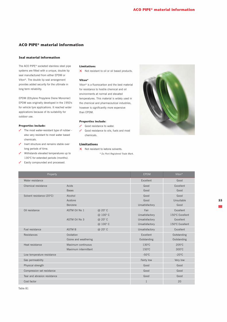
ACO PIPE® material information
Seal material information
The ACO PIPE® socketed stainless steel pipe
systems are fitted with a unique, double lip
seal manufactured from either EPDM or
Viton®. The double lip seal arrangement
provides added security for the ultimate in
long term reliability.
EPDM (Ethylene Propylene Diene Monomer)
EPDM was originally developed in the 1950's
for vehicle tyre applications. It reached wider
applications because of its suitability for
outdoor use.
Properties include:
t The most water-resistant type of rubber -
also very resistant to most water based
chemicals.
t Inert structure and remains stable over
long periods of time.
t Withstands elevated temperatures up to
130°C for extended periods (months).
t Easily compounded and processed.
Limitations
s Not resistant to oil or oil based products.
Viton*
Viton* is a fluorocarbon and the best material
for resistance to hostile chemical and oil
environments at normal and elevated
temperatures. This material is widely used in
the chemical and pharmaceutical industries,
however is significantly more expensive
than EPDM.
Properties include:
t Good resistance to water.
t Good resistance to oils, fuels and most
chemicals.
Limitations
s Not resistant to ketone solvents.
* Du Pont Registered Trade Mark.
Water resistance Excellent Good
Chemical resistance Acids Good Excellent
Bases Good Good
Solvent resistance (20°C) Alcohol Good Good
Acetone Good Unsuitable
Benzene Unsatisfactory Good
Oil resistance ASTM Oil No 1 @ 20° C Fair Excellent
@ 100° C Unsatisfactory 150°C Excellent
ASTM Oil No 3 @ 20° C Unsatisfactory Excellent
@ 100° C Unsatisfactory 150°C Excellent
Fuel resistance ASTM B @ 20° C Unsatisfactory Excellent
Resistances Oxidation Excellent Outstanding
Ozone and weathering Outstanding Outstanding
Heat resistance Maximum continuous 130°C 205°C
Maximum intermittent 150°C 300°C
Low temperature resistance -50°C -20°C
Gas permeability Fairly low Very low
Physical strength Good Good
Compression set resistance Good Good
Tear and abrasion resistance Good Good
Cost factor 1 20
Property EPDM Viton*
Table 81

ACO PIPE® Stainless Steel Pipework Systems
56
Care and maintenance
Table 82
Maintenance programme
With care taken during the fabrication and
installation, cleaning before handing over to
the client should present no special problems,
although more attention than normal may be
required if the installation period has been
prolonged.
Where surface contamination is suspected,
immediate attention to cleaning after site
fixing will encourage a trouble-free product.
Food and beverage handling, pharmaceutical
and chemical industry applications require
extremely high levels of cleanliness applicable
to each industry.
Advice is often sought concerning the
frequency of cleaning stainless steel and the
answer is quite simple - clean the metal
whenever it becomes dirty in order to restore
its original appearance. This may vary from
one to four times per year for external
applications or it may be once per day for
products installed in hygienic or chemically
aggressive applications.
Frequency and cost of cleaning is lower with
stainless steel than with many other materials
and will often outweigh the initial higher cost
of this superior product.
Stainless steel is easy to clean. Washing with
soap or mild detergent in warm water
followed by a clear water rinse is usually quite
adequate for many industrial applications. An
enhanced aesthetic appearance will be
achieved if the cleaned surface is finally
wiped dry.
Precautions
Acids should ONLY be used for on-site
cleaning when all other methods have been
proved unsatisfactory and in accordance with
manufacturers' instructions. Appropriate
personal protection equipment should be used
at all times.
Care should be taken to ensure that acid
cleaners do not spill over adjacent areas.
Solvents should not be used in confined areas
without adequate ventilation and only in
accordance with manufacturers' instructions.
Conclusion
If all the cleaning suggestions and actions in
the table below have been attempted and the
surface is still not satisfactory, stainless steel
can be mechanically cleaned or
electropolished by specialists on site. For
further information, contact the ACO Building
Drainage Helpline on 01462 816666 for help
and assistance.
Routine cleaning. Soap or mild detergent Sponge, rinse with clean water.
(e.g. washing up liquid) and water. Wipe dry if necessary.
Fingerprints. Soap and warm water or organic solvent Rinse with clean water,
(e.g. alcohol, acetone). wipe dry if necessary.
Stubborn stains and discolouration. Mild cleaning solutions (e.g. Cif, Rinse well with clean water and wipe dry.
GODDARD'S STAINLESS STEEL CARE).
Oil and grease marks. Organic solvent (e.g. alcohol, acetone). Clean after with soap and water,
rinse with clean water and dry.
Rust and other corrosion products. Oxalic acid. The cleaning solution should Rinse will with clean water. Precautions for
be applied with a swab and allowed to acid cleaners must be observed.
stand for 15-20 minutes before being
washed away with clean water.
May continue using Cif to give final clean.
Problem Cleaning Agent Comments
Note: Always read instructions on proprietry cleaning agents

Material resistance chart
57
Material resistance chart
The resistance information contained within
this table is indicative only.
AIl data is based on reactions noted at an
ambient temperature of 20˚C. Higher
temperatures will generally reduce the
corrosion resistance of the materials.
Please contact ACO if guarantees are required
of specific material suitability.
We shall arrange for tests to be undertaken
with the reagent to establish the chemical
resistance of the materials.
Legend
t Recommended.
? Suitable.
However, contact ACO for further advice.
s Not recommended.
~ No data available
Acetic Acid 20% t t t t
Acetic Acid 80% t t t t
Acetone t t t s
Alcohol (Methy or Ethyl) t t t ?
AIuminium Chloride ? ? t t
Aluminium Sulphate t t t t
Ammonia Gas (Dry) t t ~ ~
Ammonium Chloride ? ? t t
Ammonium Hydroxide t t t t
Ammonium Nitrate t t t t
Ammonium Phosphate t t t t
Ammonium Sulphate ? t t t
Ammonium Sulphide t t ~ ~
Amyl Chloride t t s ?
Aniline t t ? t
Barium Chloride t t t t
Barium Hydroxide 10% ~ ~ t t
Barium Sulphate t t t t
Barium Sulphide ~ ~ t t
Beer t t t t
Beet Sugar Liquors t t t t
Benzene t t s t
Benzoic Acid t t s t
Bleach - 12.5% Active C1 ~ ~ t s
Boric Acid t t t t
Bromic Acid ? ? ~ ~
Bromine Water s s ~ ~
Butane t t s t
Calcium Carbonate t t t t
Calcium Chloride s ? t t
Calcium Hydroxide ? t t t
Calcium Hypochlorite s ? ? t
Calcium Sulphate t t t t
Cane Sugar Liquors ~ ~ t t
Carbonic Acid ~ ~ t t
Carbon Bisulphide t t s t
Carbon Dioxide t t t t
Carbon Monoxide t t t t
Carbon Tetrachloride ? ? s t
ReagentStainless
Steel 304
StainlessSteel316
EPDM Viton
Caustic Potash t t t t
Caustic Soda 20% t t t t
Caustic Soda 50% t t t t
Caustic Soda 80% t t t t
Chlorine (Dry) ? ? t t
Chlorine (Wet) s s s t
Chloraocetic Acid ? t ? s
Chlorobenzene t t s t
Chloroform ? ? s t
Chromic Acid 50% s s ? t
Chromic Acid 10% t t s ?
Citric Acid ? t t t
Copper Chloride s s t t
Copper Cyanide t t t t
Copper Nitrate t t ~ t
Copper Sulphate t t t t
Cottonseed Oil ~ ~ s t
Cresol ~ ~ s s
Cyclohexanone ? t s s
Cyclohexane t t s t
Diethylamine ? ? ? s
Disodium Phosphate ~ ~ t t
Distilled Water t t t t
Ethyl Acetate t t ? s
Ethylene Chloride t t s ?
Ethylene Glycol t t t t
Fatty acids (Cb) t t s t
Ferric Sulphate t t t t
Fluorene Gas (Wet) s s t ?
Formaldehyde 37% t t t t
Formic Acid 90% s t t ?
Freon 12 t t t t
Fruit Juices & Pulp ? t ~ t
Furfural t t s s
Gasoline (Refined) t t s t
Glucose t t t t
Glycerine t t t t
ReagentStainless
Steel 304
StainlessSteel316
EPDM Viton
Table 83

ACO PIPE® Stainless Steel Pipework Systems
58
Material resistance chart
Hydrobromic Acid 20% s s t t
Hydrochloric Acid 40% s s s t
Hydrocyanic Acid t t ? t
Hydrogen Peroxide 90% t t s t
Hydroquinone ~ ~ s t
Hypochlorous Acid ~ ~ s t
(Chlorine Water )
Iodine s ? ? t
Kerosene t t s t
Lactic Acid 25% t t t t
Linseed Oil t t s t
Magnesium Chloride ? ? t t
Magnesium Sulphate t t t t
Maleic Acid ? ? s t
Methyl Chloride ? ? s s
Methyl Ethyl Ketone ~ ~ t s
Milk t t t t
Minerals Oils ~ ~ s t
Nickel Chloride ? ? t t
Nickel Sulphate t t t t
Oils and Fats t t s t
Oleic Acid t t t t
Oleum ~ ~ s t
Oxalic Acid ? ? t t
Palmitic Acid 10% ~ ~ t t
Perchloric Acid 10% s s ? t
Perchloric Acid 70% s s ? t
Petroleum Oils t t s t
Phenol 5% t t ? t
Phosphorous Trichloride t t t t
Photographic Solutions ? ? t t
Picric Acid t t t t
Plating Solutions ~ ~ ~ t
Potassium Carbonate t t t t
Potassium Chloride t t t t
Potassium Cyanide t t t t
Potassium Dichromate t t t t
Potassium Hydroxide t t t t
Potassum Permanganate t t t t
Potassium Sulphate t t t t
Propane Gas ~ ~ ~ t
Propyl Alcohol ~ ~ t t
Sea Water (Natural) s ? t t
Silver Nitrate t t t t
ReagentStainless
Steel 304
StainlessSteel316
EPDM Viton
Silver Sulphate t t t s
Sodium Bicarbonate t t t t
Sodium Bisulphite t t t s
Sodium Carbonate t t t t
Sodium Cyanide t t t t
Sodium Ferrocyanide ~ ~ ? t
Sodium Hydroxide t t t t
Sodium Hypochlorite ? t ? t
Sodium Sulphate t t t t
Sodium Sulphide ? s t t
Sodium Sulphite ? t t t
Sodium Thiosulphate t t t t
Stannous Chloride ? ? s t
Stearic Acid t t ? t
Sulphurous Acid ? t ? t
Sulphur ? t ~ t
Sulphur Dioxide (Dry) ? t t t
Sulphur Dioxide (Wet) ? t t t
Sulphuric Acid 50% s s ? t
Sulphuric Acid 70% s s ? t
Sulphuric Acid 93% s s ? t
Tannic Acid t t t t
Tanning Liquors t t t t
Tartaric Acid ~ ~ ? t
Toluene ~ ~ s s
Trichloroethylene t t s s
Triethylamine t t t s
Trisodium Phosphate ~ ~ t t
Turpentine t t s t
Urea t t t t
Urine t t t t
Vinegar t t t t
Water (Fresh) t t t t
Water (Mine-acid) t t t t
Water (Salt) ~ ~ t t
Whisky t t t t
Wines t t t t
Xylene ~ ~ s s
Zinc Chloride s s t t
Zinc Sulphate ? t t t
ReagentStainless
Steel 304
StainlessSteel316
EPDM Viton
Table 84

ACO PIPE® Stainless Steel Pipework Systems
59
Notes

ACO Building Drainage
ACO Water ManagementCivils + InfrastructureUrban + Landscape
ACO Sport
ACO Wildlife
ACO Technic
ACO Home & Garden
ACO Technologies plc
ACO Building Drainage
A division of ACO Technologies plcACO Business CentreCaxton RoadBedfordBedfordshireMK41 0LFTel: 01462 816666Fax: 01462 851490
e-mail: [email protected]
The ACO Group: A strong family you can depend on.
© March 2012 ACO Technologies plc. All reasonable care has been taken in compiling the information in this document. All
recommendations and suggestions on the use of ACO products are made without guarantee since the conditions of use are beyond
the control of the Company. It is the customer's responsibility to ensure that each product is fit for its intended purpose, and that the
actual conditions of use are suitable. This brochure and any advice is provided by ACO Technologies plc (the Company) free of
charge and accordingly on terms that no liability including liability for negligence will attach to the Company or its servants or
agents arising out of or in connection with or in relation to this brochure or any such advice. Any goods supplied by the Company
will be supplied solely upon its standard conditions of sale, copies of which are available on request. The Company's policy of
continuous product development and improvement renders specifications liable to modification. Information provided in this
brochure is therefore subject to change without prior notification.
ID: 18601