Embed Size (px)
Citation preview

Bulletin of the Technical Committee on
DataEngineeringMarch 2001 Vol. 24 No. 1 IEEE Computer Society
LettersLetter from the Editor-in-Chief . . . . . . . . . . . . . . . . . . . . . . . . . . . . . . . . . . . . . . . . . . . . . . . . . . . . . . David Lomet 1Letter from the Special Issue Editor . . . . . . . . . . . . . . . . . . . . . . . . . . . . . . . . . . . . . . . . . . . . . . . . Gerhard Weikum 1
Special Issue on Infrastructure for Advanced E-Services
B2B Protocol Standards and their Role in Semantic B2B Integration Engines . . . . . . . . . . . . . . Christoph Bussler 3Towards a Scalable Infrastructure for Advanced E-Services . . . . . . Michael Carey and the Propel Platform Team12Defining the Next Generation e-Business Platform: A Discussion of the Asera eBusiness Platform . . . . . . . . . . . .
. . . . . . . . . . . . . . . . . . . . . . . . . . . . . . . . . . . . . . . . . . . . . . . . . . . Anil Nori, Chandar Venkatraman, Rajiv Jain19Sell-side Channel Integration – Tavant’s Approach . . . . . . . . . . . . . . . . . . . . . . . . . . . . . . . . . . . . . . . . . . . . . . . . . .
. . . . . . . . . . . . . . . . . . . . . . . . . . . . . . . . . . .Srinivasa Narayanan, Subbu Subramanian, and the Tavant Team24Definition, Execution, Analysis, and Optimization of Composite E-Services . . . . Fabio Casati, Ming-Chien Shan30BizTalk Server 2000 Business Process Orchestration . . . . . . . . . . . . . . . . . . . . . . . . . . . . . . . . . . . . . . . . . . . . . . . .
. . . . . Bimal Mehta, Marc Levy, Greg Meredith, Tony Andrews, Brian Beckman, Johannes Klein, Amit Mital36Workflow Mediation using VorteXML . . . . . . Vassilis Christophides, Richard Hull, Akhil Kumar, Jerome Simeon41WISE: Process based E-Commerce . . . . . . . . . . . . Amaia Lazcano, Heiko Schuldt, Gustavo Alonso, Hans Schek47CrossFlow: Cross-Organizational Workflow Management for Service Outsourcing in Dynamic Virtual Enterprises
. . . . . . . . . . . . . . . . . . . . . . . . . . . . . . . . . . . . . . . . . . Paul Grefen, Karl Aberer, Heiko Ludwig, Yigal Hoffner53Towards Response Time Guarantees for e-Service Middleware . . . . . . . . . . . . . . . . . . . . . . . . . . . . . . . . . . . . . . . .
. . . . . . . . . . . . . . . . . . . . . . . . . . . . . . . . . . . . Achim Kraiss, Frank Schoen, Gerhard Weikum, Uwe Deppisch59ObjectGlobe: Open Distributed Query Processing Services on the Internet . . . . . . . . . . . . . . . . . . . . . . . . . . . . . . .
. . Reinhard Braumandl, Markus Keidl, Alfons Kemper, Donald Kossmann, Stefan Seltzsam, Konrad Stocker65
Conference and Journal NoticesICDE’2001 Call for Participation . . . . . . . . . . . . . . . . . . . . . . . . . . . . . . . . . . . . . . . . . . . . . . . . . . . . . . . . . .back cover

Editorial Board
Editor-in-ChiefDavid B. LometMicrosoft ResearchOne Microsoft Way, Bldg. 9Redmond WA [email protected]
Associate Editors
Luis GravanoComputer Science DepartmentColumbia University1214 Amsterdam AvenueNew York, NY 10027
Alon LevyUniversity of WashingtonComputer Science and Engineering Dept.Sieg Hall, Room 310Seattle, WA 98195
Sunita SarawagiSchool of Information TechnologyIndian Institute of Technology, BombayPowai StreetMumbai, India 400076
Gerhard WeikumDept. of Computer ScienceUniversity of the SaarlandP.O.B. 151150, D-66041Saarbrucken, Germany
The Bulletin of the Technical Committee on Data Engi-neering is published quarterly and is distributed to all TCmembers. Its scope includes the design, implementation,modelling, theory and application of database systems andtheir technology.
Letters, conference information, and news should besent to the Editor-in-Chief. Papers for each issue are so-licited by and should be sent to the Associate Editor re-sponsible for the issue.
Opinions expressed in contributions are those of the au-thors and do not necessarily reflect the positions of the TCon Data Engineering, the IEEE Computer Society, or theauthors’ organizations.
Membership in the TC on Data Engineering is open toall current members of the IEEE Computer Society whoare interested in database systems.
The Data Engineering Bulletin web page ishttp://www.research.microsoft.com/research/db/debull.
TC Executive Committee
ChairBetty SalzbergCollege of Computer ScienceNortheastern UniversityBoston, MA [email protected]
Vice-ChairErich J. NeuholdDirector, GMD-IPSIDolivostrasse 15P.O. Box 10 43 266100 Darmstadt, Germany
Secretry/TreasurerPaul LarsonMicrosoft ResearchOne Microsoft Way, Bldg. 9Redmond WA 98052-6399
SIGMOD LiasonZ.Meral OzsoyogluComputer Eng. and Science Dept.Case Western Reserve UniversityCleveland, Ohio, 44106-7071
Geographic Co-ordinators
Masaru Kitsuregawa (Asia)Institute of Industrial ScienceThe University of Tokyo7-22-1 Roppongi Minato-kuTokyo 106, Japan
Ron Sacks-Davis (Australia )CITRI723 Swanston StreetCarlton, Victoria, Australia 3053
Svein-Olaf Hvasshovd (Europe)ClustRaWestermannsveita 2, N-7011Trondheim, NORWAY
DistributionIEEE Computer Society1730 Massachusetts AvenueWashington, D.C. 20036-1992(202) [email protected]

Letter from the Editor-in-Chief
ICDE’2001
The International Conference on Data Engineering is being held in Heidelburg, Germany from April 2 to April6, 2001. This conference is the flagship conference for the Technical Committee on Data Engineering, the or-ganization that sponsors the Data Engineering Bulletin. This conference is one of the three key annual databaseconferences, covering the entire database field. Alex Buchmann and Dimitrios Georgakopoulos, the programcommittee chairs, have selected a very strong research program, and there is also a fine industrial program,together with strong invited speakers from IBM, SAP, and Dresdner Bank. Heidelburg is a major tourist at-traction in Germany and provides a wonderful venue for the conference. Visit the conference web site athttps://www.icde2001.org/guest for additional details. I personally am very much looking forwardto attending this conference, which should be enjoyable technically, socially, and touristically.
The Current Issue
Our world is in the process of being transformed from a world where businesses and consumers communicatewith each other via paper and extensive human ”intervention” into a world in which the communication iselectronic and mostly automated. This is the world of e-services, epitomized for most of us by Amazon.com,which is, of course, a B2C business. Hidden from the general public is a wider world of e-services in whichbusinesses are streamlining the way in which they interact with each other, the B2B world. The B2B e-servicesare probably even more important in the short term than B2C, as businesses automate the way that they dealwith their suppliers and business customers.
E-services have very large TP and database technical elements. Hence it should not be a surprise that manypeople from our ”data engineering” community have become involved in one way or another in building, orworking with folks who build e-services. Indeed, many of the concerns that have long been part of the TPand database area, scaleability, reliability, availability, performance, and data integration, are major concernsin the provision of e-services as well. Also, a new round of standards activity involving interactions betweenautonomous organizations is also under way, so that businesses (and their computing infrastructure) can under-stand each other. This standards activity is mostly centered around XML (broadly defined). These areas areparts of the ”infrastructure” that is needed for e-services to succeed.
Gerhard Weikum, our issue editor, has succeeded in his solicitation of papers from research groups that areengaged in building substantial research prototypes. More surprisingly, he has induced technical folks workingat companies actively engaged in building and selling parts of the e-services infrastructure to submit articles aswell. Hence the current issue provides a good balance between research and what is currently happening ”in thetrenches”. This is an explosive area for our field, with very substantial activity. I want to thank Gerhard for hishard work and successful efforts.
David LometMicrosoft Corporation
1

Letter from the Special Issue Editor
Internet-based e-services comprise a wide spectrum of applications from B2C (business-to-consumer, e.g., sales,auctions, or brokerage) to B2B (business-to-business, e.g., supply chains or service outsourcing) and everythingin between. Even fancy scenarios such as computerized court trials (with electronic lawyers) that may sound likescience fiction today fall into the category of conceivable e-services and may well become practice some day.Advanced forms of e-services pose challenging requirements on the underlying IT infrastructure that are muchbroader than the traditional scope of database management. In addition to extremely high scalability, respon-siveness, and availability of the data management engine, e-service platforms need to address interoperability,customizability, messaging, process management, and Web application programming and management issues.
The notion of e-services shares the fate of most other “hot topics” that it covers much ground but is itself notwell defined. This special issue is not an attempt to define the area, but merely aims to bring up and discuss themany facets of e-services across the entire spectrum. Therefore, this issue contains an unusually large number ofarticles, to provide readers with general background and representative impressions of what is going on in thiscontemporary and highly vital area, from both research and development perspectives. The issue contains sixarticles from key players in the e-service platform industry on their latest developments and industrially relevantstandards, trends, and future perspectives. There are five additional articles from research groups, industry labsas well as academia, which discuss various issues that are still beyond the current agenda of products but arelikely to become practically relevant in the not-too-far future.
The issue starts out with the article “B2B Protocol Standards and their Role in Semantic B2B IntegrationEngines”, in which Christoph Bussler gives an overview of relevant standards. The second and third papers,“Towards a Scalable Infrastructure for Advanced E-Services” by the Propel Platform Development Team and“Defining the Next Generation e-Business Platform” by Anil Nori et al., discuss requirements for a comprehen-sive e-service platform and how the developed system architectures meet them. The fourth paper on “Sell-sideChannel Integration – Tavant’s Approach”, by the Tavant team, studies the specific aspect of integrating distribu-tion channels of manufacturers from the viewpoint of an application service provider. The fifth and sixth articles,“Definition, Execution, Analysis, and Optimization of Composite E-Services” by Fabio Casati and Ming-ChienShan and “BizTalk Server 2000 Business Process Orchestration” by Bimal Mehta et al., focus on the process-oriented dimension of e-services and discuss how workflow technology contributes to current solutions.
The second, primarily research-oriented, half of the special issue begins with the paper by Vassilis Christo-phides on “Workflow Mediation using VorteXML”. This paper and the next one, “WISE: Process based E-Commerce” by Amaia Lazcano et al., report on ongoing research efforts towards more flexible, interoperable,and highly dependable workflows in an e-service environment. The ninth article, entitled “CrossFlow: Cross-Organizational Workflow Management for Service Outsourcing in Dynamic Virtual Enterprises” and authoredby Paul Grefen et al., presents results from a multi-national research project on cooperation in virtual enterprises.The tenth paper, by A. Kraiss et al. on “Response Time Guarantees for e-Service Middleware” discusses theimportance of performance guarantees in a banking environment and a mathematical approach for appropriatesystem configuration. The special issue is concluded with the eleventh article, “ObjectGlobe: Open DistributedQuery Processing Services on the Internet” by Reinhard Braumandl et al., which extends the notion of e-servicesinto Internet-based infrastructure for highly distributed, global querying.
Gerhard WeikumUniversity of the Saarland
Saarbruecken, Germany
2

B2B Protocol Standards and their Role in Semantic B2BIntegration Engines
Christoph BusslerOracle Corporation
Redwood Shores, CA 94065, [email protected]
1 Introduction
Corporations need to exchange business data to conduct business with their trading partners. Large corporationswith sometimes millions of data exchanges every day realized a long time ago that an electronic transfer ofbusiness data between their internal software systems and those of their trading partners has many advantagesover manual transmission through fax or phone. Some of them are reliability, timeliness, security, scaleabilityand traceability.
The idea of electronic transmission triggered the development of business-to-business (B2B) protocol stan-dards for business data exchange like EDI [1,2,3] and SWIFT [4] over value-added networks (VANs) [6,9,11,17]over 25 years ago [5]. For example, EDI defines the syntax and the semantics of messages exchanged. “Syntax”refers to the message layout and “semantics” to the valid data types and consistent vocabulary (data type values)used in messages. Each message is either a message with the intent of action (like “new purchase order”) or anacknowledgment message indicating the successful transmission of a message (“received purchase order”) or anerror message indicating an error situation (“reject purchase order”). The interpretation of the intent of actionhas to be standardized, too, in order to guarantee correct behavior from trading partners. For example, if a newpurchase order is accepted then the sending trading partner expects the delivery of the ordered products in thespecified time frame. In addition, each message has at least two parts: a header containing meta data about themessage itself like the sender and recipient as well as the payload containing the business relevant information.
B2B protocol standards like EDI and SWIFT are well-defined and well-established in the industry in thesense that they not only provide a defined syntax but also a defined vocabulary (in conjunction with data types)for values of the message fields. Infrastructure is in place today (software as well as networks) to deploy and touse those standards. Standard organizations are keeping the standards up-to-date with changing and expandingbusiness requirements [19,20]. Once implemented by trading partners, these standards allow the reliable ex-change of business messages. As soon as a company has implemented those standards it can participate in theglobal message exchange with little effort. The implementation itself, however, was costly since VANs charge afee to use the networks and the software implementing the standards was expensive.
In recent years two major “phenomena” changed the situation promising almost “free” business data ex-change: the adoption of the Internet [12,13] as communication medium and the development and wide-spreaduse of XML [11]. The Internet promises cheap (“free”) and widely available communication while XML
Copyright 2001 IEEE. Personal use of this material is permitted. However, permission to reprint/republish this material for ad-vertising or promotional purposes or for creating new collective works for resale or redistribution to servers or lists, or to reuse anycopyrighted component of this work in other works must be obtained from the IEEE.Bulletin of the IEEE Computer Society Technical Committee on Data Engineering
3

promises the easy definition and implementation of documents and messages exchanged over the Internet. Thebasic idea was to replace old technology with new one: using the Internet for communication rather than VANsand the use of XML as a tagged syntax of describing messages instead of existing formats like positional orcomma delimited syntax. The belief is that this combination of the Internet and XML makes it a lot “easier” (i.e.cheaper, faster) to engage in business-to-business communication then the way defined by standards like EDI orSWIFT.
However, as can be observed by looking at the work of B2B protocol standard organizations [14,16], the“easier” is not that easy after all. Using the Internet might be cheaper from an accounting viewpoint, but itdoes not provide all the functionality required for reliable message exchange. Security, availability, privacy andservice levels are some of the properties required for serious message exchanges [8] that go beyond what theInternet or XML provide. XML is - after all - a notation for syntax. It was not developed to define semantics (likevocabulary), consistency (valid use of vocabulary), security, the description of message exchange sequences orthe definition of correct interpretation of exchanged messages.
As a consequence, research and development in network security is increasing as well as the deploymentof virtual private networks (VPNs) [21,22]. Standard committees developing B2B protocols spending most oftheir time developing a framework around XML to address the functionality necessary not originally providedby XML [14,16]. Especially existing standard committees and corporations supporting B2B protocol standardslike EDI and SWIFT are working on defining the XML representation of their current semantics making thepoint that XML addresses syntax only (see swiftml [7] and EDI [18]).
Architectural components that execute message exchanges according to B2B protocol standards at runtimeare called B2B protocol engines. A B2B protocol engine is a necessary but not sufficient component in trad-ing partner communication over networks. Once messages are received they need to be processed and beforemessages are sent they need to be generated. The activity of processing or generating messages involves theback-end application systems storing the business data. A B2B integration engine is the software componentthat connects a B2B protocol engine with one or several back-end application systems to provide an end-to-endsolution.
This article will first focus on B2B protocol standards and B2B protocol engines. Afterwards the embeddingof B2B protocol engines in B2B integration engines will be briefly discussed.
2 B2B protocol standards and B2B protocol engines
A B2B protocol standard in general is the description of the message formats exchanged (e.g. purchase order),bindings to transport protocols (e.g. HTTP/S [23]), the sequencing (e.g. after sending a purchase order messagea message acknowledgment must be received), the process (e.g. after a purchase order was send a purchaseorder acknowledgment must be received), the security to be provided (like encryption, non-repudiation) andmany more properties. Some standards focus only on a subset of the properties, others provide recommendationfor the complete set.
If not every aspect of a standard is defined by the B2B standard definition itself then each trading partnerhas to agree individually with each of it’s trading partners on an implementation of the aspect. For example, if astandard only defines document types, but no transport binding, then two trading partners need to agree on thetransport binding in order to make their systems interoperable.
B2B protocol standards isolate the back-end systems from the messages sent or received over a network.This requires that a B2B protocol standard defines the content of the messages in terms of syntax and semanticsin order to be independent of the back-end application system’s syntax and semantics of data. For example, incase of purchase orders, a standard needs to define the elements of a purchase order like company identifier,address (bill-to, ship-to) and line items. Part of this is the definition of valid values for the elements. This notonly comprises individual element values but also any consistency constraints between different values. Also,
4

it needs to define the syntax used to express content like XML, comma-delimited or positional (column - rowaddressing).
The term “message” is used in context of a real exchange of content over a network. A message containsheader information as well as payload, i.e. everything required to direct the message to the correct recipient andeverything required for the recipient to interpret the message correctly if no error occurred. The term “document”is used for the pure business content. For example, the description of the elements of a purchase order as suchis a document type. It is not concerned about header information or any other data than business data content.Usually the payload of a message is of a particular document type. “Business event” is used to express the intent.For example, “create” purchase order in comparison to “update” or to “delete” purchase order. All these threebusiness events have a different effect in the enterprise.
The same type of business data might be defined by several B2B standards (e.g. purchase order in OAGISas well as RosettaNet) even within the same industry. A trading partner has to deal with all standards it’s tradingpartners require and that might mean that one trading partner has to deal with several standards at the same time.In case one trading partner exchanges messages across industries, the variety of standards is likely to increaseeven more. The multitude of purchase order standards is not really a benefit since one trading partner might notbe able to standardize on any of those but has to entertain all of them at the same time.
The following section will provide a set of criteria that can be used to classify B2B protocol standards. Ascan be seen there are many components to a B2B standard far exceeding the abilities of XML or any othersyntax. The examples given do not provide a full coverage of all B2B standards available or currently underdevelopment by standard committees. They are purely chosen to illustrate the classification.
2.1 Classification of standards
Before going into the detailed classification of B2B standards as such a higher level classification separating B2Bstandards themselves has to take place. The B2B standards and examples discussed so far described messagesthat had a certain intent. For example, the fact that a trading partner receives a purchase order indicates thata buyer wants to buy some goods and expects a purchase order acknowledgment as well as an invoice and theactual delivery of the goods. These type of B2B standards are termed “business event B2B standards” since themessages are interpreted as events that cause action in back-end systems.
However, this is not the only type of interactions between trading partners. Sometimes a trading partnerwould like to retrieve information from several back-end system as sources of information. In this case infor-mation syndication takes place. Standards that support the syndication of data are termed “syndication B2Bstandards”. A good example are news distributing organizations [24,25].
A third type of standards are “supporting standards”. These standards support the development of B2Bstandards although they can be used in other developments, too. For example, XML is of this nature. The XMLstandard can be used as the syntax for B2B messages, but also as a standard for defining the syntax of data storedin a database.
2.2 B2B protocol standards
The following discussion provides a list of classification criteria for B2B protocol standards. The criteria chosendo not include network protocol properties like those discussed in [26,27] since B2B standards use networkprotocols as transport mechanism rather than being alternatives. Not all B2B protocol standards implement allcriteria. For example, OAGIS [28] does not provide a process definition between trading partners, but RosettaNet[29] does by means of Partner Interface Processes (PIPs).
Document typesDocument types define the payload supported. XML Schema [30] and DTD [31] are popular ways of definingdocument types. Through both mechanisms the structure of a document is defined in terms of fields and sub-
5

structures. For example, a purchase order contains a ship-to and bill-to address as well as line item definitions.OAGIS, RosettaNet and EDI are examples of standards defining the payload.
SemanticsSemantics has many facets in context of B2B protocols. These areBusiness content (vocabulary):An example of business content is a product name. For example, a product
name has to match the receiver’s valid product names so that an order can be processed correctly by thereceiver. In addition, not every possible value is a correct one and consistent with other values in otherfields. Consistency rules might have to be defined between the fields of a document (and enforced duringexecution). Several approaches exist to define business content.
� Defined by standard itself. In this case the valid field values are defined by the standard itself. For example,RosettaNet provides a business dictionary, EC technical dictionary, IT technical dictionary [29] that containsvalid values. Sender as well as receiver have to map their internal values to those as defined by the standard.
� Defined by receiving trading partner. In this case the receiver requires its vocabulary to be used and the senderhas to make sure that it uses the receiver’s vocabulary correctly.
� Defined by sending trading partner. In this case the sender uses its vocabulary and leaves the translation intothe receiver’s vocabulary to the receiver.
� Trading partner identification. Trading partner identifications are part of messages sent. They also need to beunderstood by the participating trading partners and so they have to be standardized analogously to businesscontent. Some standards define a particular naming schema to be used, for example, DUNS numbers [32].
� Message identification. Message identifiers need to be agreed upon like trading partner identification. Both,sender as well as receiver need to interpret the identifier the same way.
Constants: Units of measure [33] and country codes [34] are also values that need to be agreed upon by eithertrading partners or defined by a standard itself.
Data types: Business contents can be expressed in data types. For example, an address can be defined asa structure of name, street, city, zip and country. Standards using XML schema [30] as the documentdefinition language can define data types.
Intent: A trading partner receiving a message needs to interpret that message in context of its back-end systems.The message has to be stored in the back-end system and the back-end system has to interpret the messageaccording to its intent. Interpretation consists of the
� Correct interpretation of vocabulary. The business contents of the message must be interpreted accordingto the agreement with the trading partner. This requires the correct translation into the back-end system’svocabulary.
� Correct interpretation of message and correct initiation of action. A trading partner receiving a consistentand correct message is expected to act according to the message content. For example, if a purchase order isreceived then a purchase order acceptance document has to be sent as well as the goods delivered.
Transport bindingThe transport binding defines how a message to be sent to a trading partner is encoded within the rules of anetwork protocol like HTTP/S [23], S/MIME [35], FTP [36], EDIINT [37] or beep[26]. Not all protocols definea transport binding. For example, OAGIS does not define a transport binding. Others define only a bindingwithout defining any document types. SOAP [38] falls into this category. RosettaNet defines a transport bindingas well as document types.
Message definitionIn addition to encoding of the document itself headers have to be defined as well as marshaling rules to packagethe whole message. Headers and marshaling define how the complete message layout looks like when sent overthe network protocol.
6
Exchange sequence definition� Asynchronous messages sent over a network protocol are in most cases acknowledged (either positively
or negatively in case of error). The exchange sequence definition says when acknowledgments are sentand the time limits for it. It also defines any retry logic, i.e. when to retry and how often.
� “Synchronous messages” (i.e. synchronous invocations) over a network protocol have to be acknowl-edged, too. However, in this case the acknowledgment is sent as a return parameter and not (as in theprevious case) as a separate asynchronous message.
Process definitionOn a business level business event behavior is defined. For example, a purchase order has to be followed bya purchase order acknowledgment. This exchange on a business level breaks down into several messages asdefined by exchange sequences. This business level process definition is between trading partners only. It doesnot define the processing within a trading partner.
SecurityA receiver of a message needs to know that the message is coming from the receiver that claims to have sentit, that the message was not delayed or repeated, that the message was not altered and that the message was notgenerated from an entity other than the sender. Furthermore, for a receiver it is important to be able to proof atany time that the message was sent by the receiver. This way the sender cannot deny having sent the message.Several security mechanisms are necessary to enable this behavior [39].
SyntaxSince the appearance of XML it is in many cases, if not in all of them, chosen as syntax for data exchangebetween companies. However, XML is not the only syntax available.
� Tagged document format. XML falls into the category of tagged syntax since the values are enclosed inmatching tags. Non-xml tagged syntax exists, too.
� Positional document format. In this case the values are within certain positions in a document. Forexample, between the 4. and 10. column on line 2.
� Delimited document format. In this case the values are separated by delimiters. Delimiters can be thesame (like “,”) or can be keywords.
� Binary document format. In this case the values are encoded and without program support the documentcontents cannot be read easily by a human.
Trading partner specific configurationIn many cases companies use B2B protocol standards as defined by the standards organization. However, insome cases trading partner specific modifications need to be applied to support trading partner specific require-ments.
� B2B protocol modification. In this case the B2B protocol will be modified. For example, specific fieldsare added to a document type or specific fields will be deleted. EDI uses guidelines for defining themodification. A guideline defines which parts of a document type are used for transmission. GXML [40]is a language for defining guidelines.
� B2B protocol configuration. Some standard organizations realized that trading partner specific configura-tion is required. For example, time-out or retry intervals are sometimes trading partner specific. Roset-taNet, for example, allows the trading partner specific configuration like time-out, retry interval and retrycounts.
Exactly-once behavior (or at least once or best effort) is not mentioned explicitly since the sequencing togetherwith the process definition and the message meta-data can implement this.
Each B2B standard either has to determine its settings for the above discussed criteria or the trading partnerhave to agree on those individually. If neither is done, interoperability between two companies becomes verydifficult since some of the settings are decided arbitrarily at deployment or implementation time.
7

2.3 Samples of B2B standards
There are many vertical industries and each industry has in general several B2B standards in use or in devel-opment. It is almost impossible to provide a complete list of all standards available. At [41] a comprehensivecoverage of standards can be found from almost any vertical application domain. Table 1 lists only a few ofall available standards and those under development. It illustrates the existing variety. A “B” under “Type”indicates a business event standard, a “S” a syndication standard and a “U” a supporting standard.
Table 1: Examples of Business Event, Syndication and Supporting B2B Standards
Standard Long Name Type ReferenceBizTalk B [44]Beep Blocks Extensible Exchange Protocol Framework U [26]cXML Commerce XML B [48]ebXML Electronic Business XML U [46]EDI Electronic Data Interchange B [1,2]fPML Financials Products Markup Language B [49]GISB Gas Industry Standards Board B [50]gXML Guideline XML U [40]ICE Information and Content Exchange S [24]OAGIS Open Applications Group Integration Specification B [28]OBI Open Buying on the Internet B [47]OTA Open Travel Alliance B [43]RosettaNet B [29]RSS RDF Site Summary S [25]S2ML Security Services Markup Language U [51]SOAP Simple Object Access Protocol U [38]SWIFT B [4]tpaml Trading Partner Agreement Markup Language U [52]UDDI Universal Description, Discovery, and Integration U [53]WSDL Web Services Description Language U [54]xCBL Common Business Library B [45]xkml XML Key Management Specification U [55]XML Extensible Markup Language U [31]XML Schema U [30]XML-RPC XML Remote Procedure Call U [15]XP XML Protocol Activity U [56]
2.4 B2B protocol engines
B2B protocol engines are software components that execute actual message exchanges over networks accordingto B2B standard specifications. Sophisticated engines have to support any existing B2B protocol standard. Sincesome standards are under development and not finalized yet a B2B protocol engine should be able to dynami-cally add not yet defined standards over time. In addition, sophisticated B2B engines allow the customizationof B2B protocol standards on a per trading partner basis. Some trading partners do not use B2B protocol stan-dards themselves but have a proprietary protocol defined. A B2B protocol engine must be able to implementproprietary B2B protocols as well. In addition to the B2B protocol standards they might provide additional func-tionality to required by B2B standard definitions like the persistent storage of received messages (reliability),duplicate detection (dependability) or non-repudiation (security).
B2B protocol engines need to know trading partner specific configuration information. For example, eachtrading partner has to define a network address (e.g. URL) where message are received. Trading partner infor-
8

mation like network addresses as well as identifying information like DUNS numbers are stored in a tradingpartner profile management component.
3 B2B protocol engines and B2B integration engines
A B2B protocol engine masters the communication between trading partners only. It neither interprets themessages received nor extracts or inserts business data into back-end application systems. Interpretation ofmessages and communication with back-end systems is done by B2B integration engines. B2B protocol enginesare components of B2B integration engines. The example given next will help understand the overall data flowand the B2B integration engine architecture shown subsequently.
In general, two overall directions of data-flow can be distinguished: “outbound” and “inbound” from atrading partner’s internal viewpoint. Outbound refers to the case where business data originate from a back-endsystem and have to be send out to one or more trading partners over a network. Inbound refers to the case wherea message is received from a trading partner and needs to be interpreted and inserted into a back-end system (orrejected if invalid). One trading partner’s outbound message is another trading partner’s inbound message.
One of the “famous” examples is the business data pair purchase order (PO) - purchase order acknowledg-ment (POA). A PO and a POA are related by the POA acknowledging that the PO was received, is correct and isaccepted (i.e. products will be delivered). For the trading partner that initiates the PO it is important to receivethe POA. The trading partner receiving the PO needs to generate the POA to send it back. This pair, PO - POAis a “round-trip” exchange from the initiating partner: one message sent (PO) and one corresponding messagereceived (POA). Figure 1 puts the example into context of the B2B integration engine’s functionality. The figurepoints out that the formats extracted from and inserted into the applications are different from those sent overthe network. PO’ and POA’ are in the format of the particular B2B protocol deployed between the two tradingpartners.
Application’-
PO�
POA
IntegrationEngine’
-PO’�
POA’
Internet
-PO’�
POA’
IntegrationEngine”
-PO”�
POA”Application”
Figure 1: Purchase Order B2B Exchange (“round-trip”)
A B2B protocol engine is responsible for sending out a message to a trading partner and receiving back anacknowledgment message (like the PO - POA pair). Application adapter technology is used [42] to extract busi-ness data from back-end applications or insert business data into back-end applications. Workflow technologyis deployed to take the business events coming from adapters and initiate an appropriate workflow (e.g. ap-proval workflow). The successful execution of a workflow causes the business event given to the B2B protocolengine that in turns transforms the business event into a message and sends the message to the trading partner.Instead of workflow system queueing can be used if no business logic is necessary. Figure 2 represents the basiccomponents of an B2B integration engine and its communication with applications.
Figure 2 shows that the back-end systems of the trading partners involved are not aware of each other. Italso shows that two trading partners can communicate with each other as long as they are compliant to the sameB2B protocols. It is not necessary that they have the same implementation of a B2B integration engine installed(indicated by the dashed box). The B2B integration engine with the help of the B2B protocol engine isolates theback-end system from the external world by means of the B2B protocols. More specifically, each trading partner
9

involved has to send the messages in the format as described by the B2B standard independently of the particularback-end system used. This isolation of the back-end systems by means of the B2B protocols characterize a B2Benvironment. If the back-end systems had to produce the format as understood by the trading partners back-endsystem, then an IAI (Internet application integration) solution would have been built. The implication is clear:each trading partner would have to implement as many formats as there are back-end systems at its tradingpartner’s sites.
Application-
�
Adap-ter
-
�
-
�
WorkflowManagement
-
�
Queueing-
�
B2BEngine
-
�
Internet
-
�
TradingPartner’s
IntegrationTechnology
Figure 2: Components of a B2B Integration Engine
B2B protocol standards however only address part of the problem. They isolate trading partners from eachother with a controlled syntax and semantics. However, one trading partner might have to trade with othertrading partners through many B2B protocols. In this situation a trading partner has to deal with many B2Bstandard protocols at the same time. If the same business document (like a PO) is traded using different B2Bstandards then the trading partner has to translate every PO from every B2B standard into each of its back-endsystems.
4 Summary and outlook
Looking ahead the number of B2B protocol standards can be expected to be in the low 100’s. This rather highnumber is a result of vertical application domains creating not only their own standards but several standardswithin one application domain. At this point the question arises what “standard” means in the area of B2B.Currently, many standards are proposed by standards organizations, consortiums, individual or a small groupof companies. These standards sometimes overlap or even compete with each other (for example, RosettaNetand OAGIS in the definition of document types). Consequently “standard” does not mean “globally uniquedefinition” any more.
Without further commenting on the development and the appearance of standards as such, this developmenthas an important implication for B2B integration engine technology. It is very desirable (almost a “must”) thatB2B protocol engines as well as B2B integration engines are agnostic to B2B protocol standards. If implementedwith this in mind, any new B2B protocol standard can be dynamically added and supported by a B2B protocolengine. Following this approach a company deploying a B2B integration engine can add standards over time asrequired by trading partners being added.
5 References
[1] www.x12.org[2] www.unece.org/cefact/index.htm[3] www.unece.org/trade/untdid/welcome.htm[4] www.swift.com
10

[5] www.swift.com/index.cfm?item_id=1243[6] www.swift.com/index.cfm?item_id=3184[7] www.swift.com/index.cfm?item_id=2642[8] www.swift.com/index.cfm?item_id=2160[9] www.gegxs.com/geiscom/template.jsp?page=1&id=44[10] www.ipservices.att.com/products/product.cfm?productid=edi&disp=techspecs[11] www.w3.org/XML/[12] www.fnc.gov/Internet_res.html[13] webopedia.internet.com/TERM/I/Internet.html[14] lists.w3.org/Archives/Public/xml-dist-app/[15] www.xmlrpc.com/[16] discuss.develop.com/soap.html[17] www.edi-info-center.com/html/vans.html[18] www.edi-info-center.com/index.html#XML[19] www.x12.org/x12org/Subcommittees/dev/dmwkreqform.doc[20] www.x12.org/x12org/Subcommittees/dev/Y2K.htm[21] www.internetwk.com/VPN/default.html[22] kubarb.phsx.ukans.edu/˜tbird/vpn.html[23] webopedia.internet.com/TERM/S/SSL.html[24] www.icestandard.org/[25] www.egroups.com/files/rss-dev/specification.html[26] www.ietf.org/ids.by.wg/beep.html[27] www.w3.org/Protocols/[28] www.openapplications.org/[29] www.rosettanet.org[30] www.w3.org/XML/Schema[31] www.w3.org/XML/[32] www.dnb.com/dunsno/dunsno.htm[33] www.unece.org/cefact/rec/rec20en.htm#Top[34] www.unece.org/cefact/locode/loc002.zip[35] www.ietf.org/html.charters/smime-charter.html[36] www.w3.org/Protocols/rfc959/[37] www.ietf.org/html.charters/ediint-charter.html[38] www.w3.org/TR/2000/NOTE-SOAP-20000508/[39] Stallings, William: Network Security Essentials: Applicationsand Standards, Prentice Hall, ISBN 0130160938[40] www.edifecs.com/b2b_resources_guideline.jsp[41] www.oasis-open.org/cover/[42] java.sun.com/j2ee/connector/[43] www.opentravel.org/[44] www.biztalk.org[45] www.xcbl.org/[46] www.ebxml.org/[47] www.openbuy.org/[48] www.cxml.org/home/[49] www.fpml.org/[50] gisb.org/imp.htm[51] www.s2ml.org/[52] www-106.ibm.com/developerworks/library/tpaml.html[53] www.uddi.org[54] msdn.microsoft.com/xml/general/wsdl.asp[55] www.verisign.com/developer/xml/xkms.html[56] www.w3.org/2000/xp/
11
Towards a Scalable Infrastructure for Advanced E-Services
Michael Carey and the Propel Platform Team�
Propel1010 Rincon CircleSan Jose, CA 95131
www.propel.com
Abstract
In this paper, we provide a brief overview of the Propel Distributed Services Platform, the infrastructure compo-nent of the recently announced Propel Commerce System. The Propel Distributed Services Platform is Internetinfrastructure software that provides an integrated set of core services for developers of mission-critical, data-centric, e-business applications. It is designed to provide the foundation for future as well as current Propelproduct offerings. We list the current problems and key requirements that have driven the design of the PropelPlatform and then describe the resulting system architecture and highlight its feature set.
1 Introduction
At Propel, we are currently putting the finishing touches on our initial product offering, the Propel CommerceSystem. Figure 1 gives a high-level view of the overall system. The Propel Commerce System is a full-featurede-commerce software product made up of three key elements: The Propel E-Commerce Suiteis designed tosupport customizable retail Web sites for multi-channel (e.g., Internet, physical stores, catalog) retailers forwhom integration with existing back-office systems is essential. The Propel Interaction Designstop off theE-Commerce Suite with a set of pre-tested design patterns, JSP templates, and tools for use by shoppers, mer-chandisers, customer support staff, and e-commerce Web site administrators. The Propel Distributed ServicesPlatform, an integrated set of core services that provides a scalable, fault-tolerant infrastructure for e-businessapplications, is the topic of the remainder of this paper.
2 Building E-Services Today
The majority of e-business applications today are based on a variant of the three-tier Web site architecturedepicted in Figure 2. (Not shown are the hardware load balancers or firewall boxes that are also part of an e-business Web site.) End users interact with the e-business application from their Web browsers via http requests.
Copyright 2001 IEEE. Personal use of this material is permitted. However, permission to reprint/republish this material for ad-vertising or promotional purposes or for creating new collective works for resale or redistribution to servers or lists, or to reuse anycopyrighted component of this work in other works must be obtained from the IEEE.Bulletin of the IEEE Computer Society Technical Committee on Data Engineering
�Nicolas Adiba, Michael Blow, Michael Carey, Steven Kirsch, David Li, James Lucky, Sambavi Muthukrishnan, Ivan Oprencak,Rajendra Panwar, Runping Qi, David Rieber, Mary Roth, John Shafer, Brian Sterling, Tolga Urhan, Bert Van der Linden, Brian Vickery,Dan Wineman, and Kuan Yee.
12

Merchandising PersonalizedShopping
OrderManagement
CustomerRelationshipManagement
Analyticsand
Reporting
Propel E-Commerce SuitePropel E-Commerce Suite
Propel Distributed Services PlatformPropel Distributed Services Platform
Global Cache
Scalable, Fault-Tolerant, Clustered Messaging System
Integrated Search & Queuing
Advanced Deployment
Performance & Services Management
In-Memory & Disk-BasedData Management
Customer Touch PointsWeb, Store, Call Center, Catalog, Wireless, Kiosk
LegacySystems
Best ofBreedApps
3rd PartySolutions
Propel Interaction DesignsPropel Interaction DesignsDesign Patterns Components and
FrameworksReference
Implementations
XML/JavaAdapters
PropelCommerce
Integration Layer
Figure 1: The Propel Commerce System.
These requests are fielded by an array of Web servers that can serve static pages and route requests to theapplication server tier. Load balancing is usually accomplished across the Web server tier via a hardware loadbalancer made by a vendor such as Cisco or Alteon. The application server tier hosts the application’s businesslogic, which is often replicated across a set of application servers for scalability. Load balancing at this levelis typically accomplished via Web server plug-ins that direct requests initially to any application server andthen perform “sticky routing” to direct subsequent requests for the same session back to that server. The dataserver tier contains the data management facilities required to support the application, which can often includea database management system, a search engine (for full-text searching), a persistent message queuing product,and connections to back office systems such as the enterprise’s ERP system, existing data warehouse, and otherlegacy data systems.
WebServer
WebServer
WebServer
WebServer
WebServer
WebServer
WebServer
WebServer
Web Server Tier
E-CommerceApplication
E-CommerceApplication
CustomApplication
Application Server Tier
E-CommerceApplication
SearchEngine
DatabaseSystem
E-CommerceApplication
Back OfficeSystems
QueueingPackage
Data Server Tier
Figure 2: Typical Three-Tier Web Site Architecture.
13
The standard three-tier Web site architecture, while workable, has a number of limitations. A few of its moresignificant limitations are:
1. Scalability is provided at the Web server tier by adding Web servers, and (to a somewhat lesser extent) atthe application server tier by adding more application servers running copies of the application. However,scalability is limited by the data server tier. There, the application is at the mercy of the individualcomponents’ (database system, search engine, queuing system) abilities to scale. When it is even possible,scaling at the data server tier often requires rolling in expensive, high-end SMP systems and software.
2. The e-commerce application developer is required to programmatically piece together data drawn fromthe various data sources on the data server tier. For example, to perform tasks that require access todatabase data, full-text search, and queue entries, the developer must use three different APIs, hand-codethe equivalent of query execution plans, and utilize careful programming techniques to try and avoidcross-source data consistency problems.
3. For application-level scalability, the e-commerce application developer often ends up having to staticallypartition their data into multiple databases at the application level (e.g., one database for current auctions,a separate database for recent auctions). Again, this can result in the developer having to hand-code queryexecution plans when the need arises to operate on data that crosses partitioned database boundaries.
4. Managing the system’s configuration and day-to-day operation, as well as doing performance tuning, istricky at the data server tier. In addition to managing the Web server and application server tiers, thesetasks all require the system administrator to deal with the administration and monitoring aspects of anumber of disparate data systems.
3 E-Service Software Infrastructure Requirements
The Propel Distributed Services Platform has been developed to address the shortcomings of these existing ar-chitectures. Our goal was to develop an integrated software infrastructure that e-business application developerscould build on rather than having to piece together and then attempt to scale, administer, and tune a set of indi-vidual (and often otherwise unrelated) components. We started with a clean slate and the following high-levelrequirements:
1. The Platform should provide “access to data”. That is, it should be designed for use in developing e-business Web sites and other advanced e-services for which data (and thus dynamically generated content)is central.
2. The Platform should be incrementallyscalable so that a given e-business site can be scaled up cost-effectively over time in direct proportion to increasing demands for the services provided by the site.
3. The Platform should be highly-available. It should be designed for a 24x7 world, avoiding downtime inthe face of component failures and/or the need to deploy new versions of data or code.
4. The Platform should provide high performance (subject to satisfying the previous goals). More specif-ically, the primary performance goal should be to provide fast, stable response times under high loadconditions.
5. The Platform should exploit modern commodity hardware trends. Two such trends are the ease of assem-bling a large amount of processing capacity via a large “shared nothing” network of inexpensive machines(Sun Netras or rack-mountable Intel boxes) and the low cost of relatively large main memories for suchmachines.
14

6. The Platform should make it “easy” to build and administer e-business applications that are themselvesscalable and highly-available.
7. The Platform should be developed using Java, for Java applications, in order to achieve a balance oftime-to-market, robustness, and ease of evolving the system over time.
8. The Platform should be able to work together with an application developer’s preferred Web server, ap-plication server, and relational database system products.
4 The Propel Distributed Services Platform
The Propel Distributed Services Platform provides an integrated set of services for use in building enterprise-level Java applications. Figure 3 lists the key components of the Propel Platform and illustrates how its useadvances the standard three-tier Web site architecture shown in Figure 2. The Propel Distributed ServicesPlatform enhances the site infrastructure, working together with industry-leading SQL database servers, J2EEapplication servers, and popular Web servers to provide a runtime environment that has been designed to sig-nificantly simplify the development and deployment of scalable, highly-available, e-business applications. Itsmajor components are:
Performance Mgmt & System Admin
In-MemoryDatabase
Distributed Data Managers
DatabaseSystem
Propel Distributed Services Platform
WebServer
WebServer
WebServer
WebServer
WebServer
WebServer
WebServer
WebServer
Web Server Tier
E-CommerceApplication
E-CommerceApplication
CustomApplication
Application Server Tier
E-CommerceApplication
CustomApplicationMerchandising Order
ManagementCustom
ApplicationCustomer
RelationshipManagement
Analytics &Reporting
Advanced Deployment
Integrated Search & Queuing
Global Cache
Scalable, Fault-tolerant, Clustered Messaging System
Back OfficeSystems
Java Object Mapping
Figure 3: Propel Commerce System Web Site Architecture.
Clustered Messaging System:This component is the heart of the Propel Platform. The Clustered MessagingSystem provides a set of Java IPC APIs that are used by Platform services (and made available to interestedapplication services) for inter-service communications. It supports a model where messages may be sent eitherto a named service or to a specific registered instance (provider) of a named service. It performs automaticload-balancing and failure management for registered services, and provides several different request routingprotocols (master/slave, multi-master, and subscription). It runs on two or more nodes (“message hubs”) of thesite and is itself a clustered, scalable service - additional reliability and message throughput can be achieved
15
by scaling up the number of message hubs. Its logically centralized nature contributes to system manageabilityand enables optimizations intended to minimize physical resource consumption and boost throughput underhigh loads (by reducing the number of required TCP/IP connections and allowing service-to-service messagebatching).
Distributed Data Management:This component provides an incrementally scalable framework for manag-ing e-business data. It uses a collection of in-memory data managers (the TimesTenTM database managementsystem is a component of our system) in concert with the application developer’s preferred disk-based databasesystem to store and manage e-business data. The in-memory data managers store tables in main memory ratherthan on disk to reduce query latency, using checkpoints and logging to ensure data durability in the event ofsystem failures. Performance critical tables are placed under the control of one or more in-memory data man-agers, while less frequently accessed (or extremely large) data sets continue to reside in the disk-based databasesystem. Data replication is utilized to ensure high availability and access-handling scalability for the in-memorydata, and the system has been designed to permit partitioning of tables across multiple data managers for addedscalability and capacity. Data placement is a physical design decision that is completely transparent to applica-tion programmers - applications can access Platform-managed data via the provided data access APIs as thoughit were contained in a single data manager. This eliminates any need for application-visible database partitioningor manual programming of cross-database queries.
Integrated Search:Also included in the Distributed Data Management component of the Propel DistributedServices Platform is support for full-text indexing and querying of the text columns of Platform tables. Thisenables a single Platform query to combine both text search and traditional (parametric) database search predi-cates, which can significantly simplify the development of e-business search features. Match-any and match-allsearches are supported, as are application-provided tables containing stop words, synonyms, and common mis-spellings for any text column. Results are relevance-ranked, and ranks are made accessible for use in sorting andpresenting query results. Full and incremental text index refresh modes are supported; per-transaction refresh isplanned as well. Internally, the integrated search facilities ride on the in-memory Distributed Data Managementinfrastructure to achieve fast, reliable, scalable text searching.
Integrated Queuing:The Distributed Data Management component also includes built-in support for per-sistent queues. Queues are active, table-like data structures managed by the in-memory data managers forperformance. Like tables, queues have schemas, and queue entries are typed. The Propel Platform’s queuesenable distributed services to reliably enqueue information for one another, allowing them to communicateasynchronously yet be assured that information loss will not occur in the event of system failures. Two forms ofdequeue operation are supported, both of which use query predicates and ordering to specify the entries that anapplication wishes to dequeue. One form atomically removes the dequeued entries from the queue and returnsthem to the application, while the other form atomically updates their state in an application-specified mannerbut leaves them in the queue for later use. Since queues are part of the Propel Platform’s Distributed DataManagement framework, the Platform’s transaction management capabilities apply to queues, and queues canbe queried and joined with data from regular tables and other queues.
Java Object Mapping:To provide a natural programming model for use by Java application developers,the Propel Distributed Services Platform includes a layer of Java APIs known as the Java Object Mappinglayer (OM layer). This layer provides a high-level Java object “view” of all Platform-managed data (includingboth data in tables and entries in queues). Its APIs are based on the widely used Java bean programmingparadigm. The beans used by an application are automatically generated by the OM layer via an XML-based toolincluded with the Platform. The supported mappings include a variety of relationship types based on underlyingreferential integrity constraints and application-provided XML annotations. The OM layer provides access torelated objects as interconnected Java beans. Both static and dynamic query-based access to data is provided.Anticipated queries can be specified at bean generation time and used to create simple-to-call methods that fullyencapsulate complex database predicates (including both local predicates and path expressions). In addition, adhoc queries can be built and executed programmatically at runtime. A set of generic data access and transaction
16

management APIs are also provided by the OM layer.Global Cache: The Global Cache is a hierarchical caching service intended for caching such objects as
fragments of generated dynamic HTML content. For the e-business applications that the Propel Platform aimsto serve, most HTML pages are dynamically computed based on Platform data content and on characteristics ofthe user for whom the page is being assembled. Site scalability can be significantly enhanced through the cachingof such content, as it is very often reusable for a period of time (e.g., until the next deployment of product catalogor pricing information in the case of a product information page). Page fragments rather than just whole pagesare cached to support reuse of dynamic content despite full personalization. The Global Cache’s architectureconsists of a level 1 cache on each application server plus a level 2 cache server that runs on one or more nodesof the site. The level 2 cache server is scalable through partitioning, and a least-recently used policy is used tomanage the placement of fragments within the distributed cache. This architecture permits the caching capacityof the system to be scaled much more economically than architectures based solely on application server caches.
Advanced Deployment:High availability requires that new data and new code be deployable to a live e-business site without downtime or interference with ongoing sessions. To support this requirement, the PropelPlatform includes an Advanced Deployment service that manages a multi-stage (offline, staging, and production)Web site model. For deployment of new application code, the Propel Advanced Deployment service interactswith the Clustered Messaging System to incrementally apply and then enable changes to services and serverswithin the site. For deployment of new database content, the OM Layer provides built-in support for differentialdata versioning. A table can be designated as versioned, and the OM Layer will then transparently modify theapplication’s data accesses (on the fly) to select only that data associated with the session’s target version. ThePropel version representation requires space proportional just to the degree of change, not to the overall cardi-nality of a given versioned table. Both forward and backward rolling of deployed data changes are supported,and emergency change support is provided as well.
Distributed Services Manager:Last but certainly not least, the Propel Distributed Services Platform includesa Web-based system administration console called the Propel Distributed Services Manager. Through this con-sole, an e-business site operator can configure and monitor the health and performance of all aspects of the site– including hardware (load balancers, Web servers, application services, and other machines within the site)as well as software (both Platform services and application services). The console includes pages that providereal-time performance reporting as well as viewing and filtering of the system-wide event logs and support forautomated alerts. Database administration pages are provided as well, and the console has an extensible internalorganization that permits new application services to be made known to the console, either for generic admin-istration through default pages or for custom administration through JSP pages written specifically to manage agiven service.
5 Summary and Future Plans
In this short paper, we have provided a brief summary of the motivation for and an overview of the Propel Dis-tributed Services Platform. The system integrates a number of ideas from the distributed database and transactionprocessing worlds and has been designed to enable a “distributed system services approach” to the developmentof mission-critical e-business Web sites. In particular, it provides a set of components and interfaces intended tosignificantly simplify the problem of constructing and managing data-intensive Web applications as sets of com-municating, scalable, highly-available services. Our future plans include additional work on object and querycaching, flexible (XML) data management, geographically distributed e-business Web sites and applications,and hands-off performance management.
17

Defining the Next Generation e-Business Platform: A Discussionof the Asera eBusiness Platform
Anil Nori, Chandar Venkatraman, Rajiv JainAsera Inc.
600 Clipper DriveBelmont, CA [email protected]
Businesses need to leverage the Web to gain and maintain competitive advantage in a way that is cost-effective and sustainable over the long run. With the myriad of choices currently available, the challenge is tofind an integrated, robust e-business solution that allows a company to leverage existing applications, rapidlyadapt to the unique needs of the business, and continually evolve as business requirements change over time.
The Asera eBusiness Platform is a breakthrough, integrating architecture that provides a complete, adaptivee-business platform designed to address today’s needs for integration, adaptability and evolution. The AseraeBusiness Platform:
� Provides a complete e-business foundation, now and for the future
� Allows for rapid integration, deployment and continual evolution of complex business processes
� Delivers a uniquely tailored, but unified user experience
� Supports mission-critical applications in a robust industrial-strength environment
This paper motivates the need for a next generation eBusiness platform and provides a brief overview of theAsera eBusiness Platform.
1 The Need for A Next Generation eBusiness Platform
Companies face a number of challenges in choosing and implementing the right software and technology solu-tions to support their business endeavors. This has become particularly problematic in recent years as companiesattempt to leverage existing practices, systems and resources across the Web. Critical to success in this envi-ronment is the ability to identify and build on a platform that will cost-effectively support both the current andfuture needs of the business.
Today’s business models dictate that companies integrate their businesses tightly with those of their tradingpartners, suppliers and customers. Critical to achieving this integration is a robust e-business platform thatcan not only afford real-time connectivity across multiple business constituents but also automate and integratecomplex business processes across the extended value chain.
Moreover, as companies are continually looking to leverage technology to better serve the different needsof the business, it is natural for them to want to pursue best-in-class applications and technologies for each
Copyright 2001 IEEE. Personal use of this material is permitted. However, permission to reprint/republish this material for ad-vertising or promotional purposes or for creating new collective works for resale or redistribution to servers or lists, or to reuse anycopyrighted component of this work in other works must be obtained from the IEEE.Bulletin of the IEEE Computer Society Technical Committee on Data Engineering
18

business area or function. However, such a strategy results in the monumental task of integrating a diverseset of applications that are, at best, difficult to integrate. Particularly problematic is the fact that best-in-classapplications are often not designed to work with other applications, as they are proprietary in nature.
While there is a need to integrate complex business processes, current integration technologies such asEnterprise Application Integration (EAI) and portal technologies tend to address the integration problem atmerely a data level or just at the user interface level. As a result, companies find themselves having to:
1. Relax their requirements –Instead of pursuing best-in-class applications for each business area or func-tion, companies acquire a single vendor solution. The solution provides the “tight” integration they werelooking for, but at the expense of providing cutting-edge functionality and technology provided by a com-bination of best-in-class solutions; or
2. Settle for lower levels of integration –Companies pursue best-in-class applications with the desired func-tionality in each area, but at the cost of not being able to tightly integrate each application across the restof the company’s systems. They settle for lower levels of integration, which do not offer the power andflexibility of a tightly integrated solution; or
3. Build it themselves –Companies that do not wish to loose out on best-in-class application functionalityor tight levels of integration could invest heavily in in-house development efforts to achieve the desiredresult. However, such projects are costly, resource-intensive and take a long time to deploy. Moreover, theresulting solutions are easily adapted neither to the different needs within the business nor to the needs ofbusiness over time.
It is important to note that most of current enterprise applications (e.g. ERP, Supply Chain) were designedto model internal business processes only and are never meant for customer-centric business over the Internet.Even if the existing packaged applications were to be physically integrated, the integrated environment does notmodel the customer-centric business processes like customer interactions, entitlements, personalization, brandedpresentations, etc. So, key to successfully integrating and to web-enabling enterprise applications is the abilityfor rapid design, deployment and maintenance of customer-centric business processes.
In addition, companies also need their e-business solution to have the capability of rapidly being personalizedto meet the unique needs of various constituents - company employees, trading partners, suppliers and customers.They need to be able to quickly personalize user interfaces, workflow, content and context for every applicationused by the company’s constituents.
It is also critical to establish a systems environment that can support continuous evolution of a company’schosen e-business solution. Today’s environment clearly necessitates the need to react to constantly evolvingbusiness strategy and technologies. While pursuing the right set of application functionality at the right level ofintegration, the solution must also be built so that it is flexible enough to support any future software revisionsor changing business requirements.
Further, if a best-in-class application vendor falls behind in technology and/or functionality, companies arefaced with the difficult task of replacing it with an equivalent application or technology from another vendor andrepeating the entire, often difficult, task of rolling out a whole new system.
In summary, companies today are seeking an e-business platform that will enable them to:� Integrate complex business processes across the entire value chain and also disparate software appli-
cations, legacy and third-party systems within an enterprise; to develop new, customer-centric businessprocesses
� Adaptall application functionality to specific businesses and users� Evolvethe combined solution as business strategies and technologies evolve
And most companies need this to happen at Web speed. Unfortunately, most of today’s existing e-businessplatforms fall short when it comes to meeting any of these needs.
We believe there is a strong need for the next generation e-business platform and that the Asera eBusinessPlatform is designed and implemented to meet the enterprise requirements and challenges.
19

2 The Asera eBusiness Platform
The Asera eBusiness Platform is a breakthrough, integrating architecture that provides a complete, adaptive e-business platform designed to address today’s needs for integration, adaptability and evolution. The platform is acomprehensive e-business application development and deployment foundation that enables tight integration of acompany’s existing systems with external systems and best-in-class applications. It delivers a high-performancee-business solution that can be configured and personalized to meet the unique needs of the business and theindividual users.
ApplicationDeliveryFramework
Portal Manager
• Objects• Administration• Content• Layout
Personalization Manager
• Rules Based Personalization
• Content Personalization
Entitlement Manager
• Rules• Profiles• Relationships
Content Manager
• Publish• Delivery• Management
Catalog Manager
• Aggregation• Taxonomy• Parametric
Search
Asera Development Workbench
PresentationFramework
Interaction Flow
• Screen Flow• Visual Modelling
Templates
• Multi-level HTML Templates
• Wireframes
Filters
• Behaviour Filters• Style Sheets• Display Filters
Devices
• Wireless(PDAs, Cell)
• Wireline (Web)• Other
ApplicationInfrastructureFramework
Usage Tracking
• Logging• Tracing• Site Usage
Globalization
• Locale• Character Set• Date / Time• Currency
Security
• Single Sign-On• Authentication• Authorization
Scalability
• Caching• Automatic
Failover
Messaging
• Guaranteed Delivery• Publish / Subscribe• Information Bus• Batch / Real Time
BusinessProcessFramework
Workflow Engine
• Business Logic
Business Objects
• Attributes• Relations• Methods
Rules Engine
• Business Object Rules
• Named Rules
Persistence
• Adapters• Connectors
ApplicationExecutionFramework
Application Server
• Load Balancing• Clustering
Repository
• Rules Based Personalization
• Content Personalization
• Session Services• Transaction
Management
Inte
grat
ion
Fram
ewor
k
User Interface Integration
• Common Presentation• Single Sign-on• Entitlements• Portal
Business Process Integration
• Integration Flows• Business Logic
API Integration
• Java APIs• XML APIs• JDBC
Data Integration
• EAI• Common Schema• Database Triggers
Figure 1: The Asera eBusiness Platform.
Through its integrated, layered approach, the Asera eBusiness Platform facilitates rapid deployment of newe-business applications. To do this, the platform provides the following features:
� A complete e-business development environmentthat includes a robust development workbench. Theworkbench includes an Interactive Development Environment (IDE) for:
– Building and/or deploying new applications– Configuring and personalizing existing applications– Extending existing applications
� A solid integration frameworkthat allows for optimal integration of a company’s complex business pro-cesses across external systems and third party applications.
� A complete framework for personalized application deliveryof the user experience, including portal ad-ministration, entitlement, rules-based personalization and content management.
20

� A unique framework for presentation of application data, including screen flow, template management,style sheets, and wireless devices.
� A robust and flexible framework to abstract e-business processes and application data. The frameworkincludes a powerful and configurable workflow engine and a comprehensive set of business objects tosupport a eBusiness processes.
� An infrastructure frameworkthat offers a rich set of core application functions such as globalization,security, caching, fault-tolerance and messaging.
� A robust execution frameworkthat provides a runtime execution environment for e-business applications.The execution framework includes an application server environment and a repository interface manager.
3 Benefits of the Asera eBusiness Platform Design
As a result of its layered approach, design philosophy and robust functionality, the Asera eBusiness Platformis scalable, flexible and extensible. Each of the components of the platform combine to offer an environmentwhich offers the following design features and benefits:
The Asera eBusiness Platform is Designed for Rapid Integration, Development and Change.
The Asera eBusiness Platform is designed to deliver an environment that supports rapid and dynamic integrationof data and business processes across the extended enterprise. As a result, the platform provides the followingbenefits and functionality:
� Rapid Integration. Businesses can support a complete commerce model that delivers all key compo-nents of the commerce value chain by rapidly integrating business processes and any number of relatedapplications across the extended enterprise. They can rapidly integrate external systems, best-in-classapplications and existing enterprise software into a unified e-business environment.
� Rapid Development.Enabling eBusiness requires customer, Internet centric business processes to bedesigned and implemented. By developing unified business processes for presentation, personalization,entitlements and so on, seamless integration across multiple applications can be achieved.
� Multiple Levels of Integration.Businesses can choose to integrate with external systems and third partyapplications at the right level for them, taking into consideration both the specific technology of the appli-cation and specific business requirements. Third party applications and external systems can be integratedat multiple levels to the platform - ranging from loose integration (providing single sign-on access to therelevant applications) to the tightest level of integration in which application engines are “plugged” intothe platform (providing complete integration of business data and application workflow).
� Transparent Extension and Replacement of Applications.As new technology innovations or businessrequirements emerge, integrated third-party application components can easily be extended or replacedwithout any disruption to existing systems.
� Data Aggregation from Disparate Sources.Data can be aggregated from any number of disparate sourcessuch as external partner systems, internal database, Enterprise Resource Planning (ERP), Customer Re-lationship Management (CRM), Sales Force Automation (SFA), and legacy systems, external Web sites,news feeds, corporate collateral and user-generated content. The aggregation of data can be achievedeither in batch mode or in real time, depending on how frequently the information needs to be updated.
� Multiple Protocols for Messaging.The platform supports a solid messaging framework that supportsmultiple protocols such as HTTP, JDBC, RMI, and COM. Support for new emerging standards like SOAPand UDDI is also planned.
� Numerous Formats for Business Document Exchange.The platform also supports a comprehensive frame-work for business document exchange by supporting various B2B protocols and standards such as Roset-taNet, cXML, CBL, OAG, OBI, FpML, BizTalk and EDI.
21

The Asera eBusiness Platform is Designed to Deliver a Unified User Experience.
The Asera eBusiness Platform is designed to deliver a unified user experience across any e-business applicationfunctionality, both within an enterprise and to the enterprise’s trading partners. As a result, the platform is ableto deliver the following benefits:
� User Authentication.The platform provides the tools to authenticate users when they first sign on. Specificaccess privileges dictate what applications the user has access to as well as what they can accomplishwithin each application.
� Single Sign On and Navigation Transparency.Users need to sign on only once to access any e-businessapplication functionality. Users navigate among multiple applications in a seamless, continuous mannerand are completely unaware when they move from one application to another.
� Ability to Tailor Unique User Experience.Each user is presented a unique user experience that is definedby a unique “user business process”. User interface, workflow, e-business content and context can eachbe tailored to a user’s unique role within the enterprise.
� User Experience Adapts to Changes.Every user experience is completely adaptive. When new applica-tions are added, the existing user experience (in terms of workflow, look and feel, user entitlements), canbe adapted to include the newly integrated application functionality – and can be done seamlessly, rapidlyand with tight levels of integration.
The Asera eBusiness Platform is Designed for Industrial Strength.
The Asera eBusiness Platform is designed for industrial strength deployment, scalability and performance. As aresult, the platform provides the following benefits for a company’s mission-critical applications:
� Fault Tolerance.Applications deployed on the platform are fault tolerant. Since the platform uses andsupports a clustered environment for fault tolerance along with an enterprise-strength infrastructure, usersessions can transparently fail over to a different node if one node crashes.
� Change and Upgrade Transparency.The platform is optimized for isolating changes or upgrades in ordernot to have any disruption of service. Application changes, platform upgrades, functionality releases andregular maintenance events do not require any application re-programming or disruption of service.
� Granular Delivery of Functionality.Application functionality can be delivered on a granular basis, muchlike the cable television model. Users select and pay for only those features that they want to use.
� Incremental Enhancements.The platform is optimized to support incremental enhancements. Users caneasily and immediately take advantage of small increases in functionality rather than waiting and/or payingfor major releases in which they might only be interested in a subset of the newly deployed functionality.
� Device Independence.Asera applications can be delivered over a device-independent, standards-basednetwork infrastructure that supports the Web, mobile and handheld wireless devices.
4 Summary – The Next Generation e-business Platform
The Asera eBusiness Platform provides an architecture that allows for rapid and tight integration of complexbusiness processes and software solutions across the extended enterprise to provide companies a unified andpowerful e-business environment. Its flexible architecture affords companies the luxury of using tightly inte-grated best-in-class applications while also allowing them to adapt and evolve the system continually.
The platform provides the ability to adapt e-business solutions to present a unique user experience to eachend user. The user interface, workflow, e-business content and context can each be tailored to deliver a unique“user business process” for each user. The platform is optimized for industrial strength scalability, reliabilityand availability, and is designed to support continual enhancements, change isolation and granular delivery ofapplication functionality.
The Asera eBusiness Platform is the next generation e-business platform that companies need as the foun-dation for their corporate e-business strategy.
22

Sell-side Channel Integration - Tavant’s Approach
Srinivasa Narayanan, Subbu Subramanian, and the Tavant Team�
Tavant Technologies542 Lakeside Drive #5, Sunnyvale, CA 94085
Contact : fsrinivas.narayanan, [email protected]
Abstract
This paper describes the challenges in building a next generation e-business solution that allows businessesto manage their sell-side distribution channels especially when the channels involve intermediaries such asdealers. We present the Tavant platform that provides a solution to this complex problem and discuss some of itsmain features and components. We describe the Channel Configurator component that provides a framework tosupport the high-configurability requirements of the channel. We also discuss the platform’s support for time-based transactions such as rentals which is becoming a prominent transaction model in the sell-side channel.
1 Introduction
Over the past few years, the web has revolutionized the way corporations conduct their businesses. From allow-ing companies to deal directly with customers, to enabling businesses to interact with one another in an efficientway, the web has impacted the functioning of businesses in a hitherto unprecedented manner. In this paper, wediscuss the challenges in building a next generation e-business solution that allows corporations to manage theirsell-side distribution channels. We discuss the dynamics of complex, fragmented and multi-brand distributionchannels that involve various intermediaries (such as dealers, large buyers, etc.), and Tavant’s unique approachto addressing its needs.
Manufacturers sell products in different ways - some sell directly to customers, while others develop exten-sive, and sometimes exclusive, distribution channels to sell their products. The sell-side solutions being builttoday are focused largely on enabling manufacturers to establish direct relationships with customers and do notcater to the needs of the various partners in the distribution channel. Tavant’s sell-side channel integration so-lution focuses on maximizing the economic value of sell-side distribution channels by making it easier for allparticipants to interact, leverage each others knowledge and customers, and gain transparency in the channel.
Figure 1 illustrates an example sell-side distribution channel for a construction equipment manufacturer.The channel partners include dealers, distributors, and national chains. The channel partners usually are in-dependent, have their own geographically localized brands, and have relationships with multiple brands and/ormanufacturers that may compete with each other. The channel partners are an essential part of the manufacturer’s
Copyright 2001 IEEE. Personal use of this material is permitted. However, permission to reprint/republish this material for ad-vertising or promotional purposes or for creating new collective works for resale or redistribution to servers or lists, or to reuse anycopyrighted component of this work in other works must be obtained from the IEEE.Bulletin of the IEEE Computer Society Technical Committee on Data Engineering
�see http://www.tavant.com
23
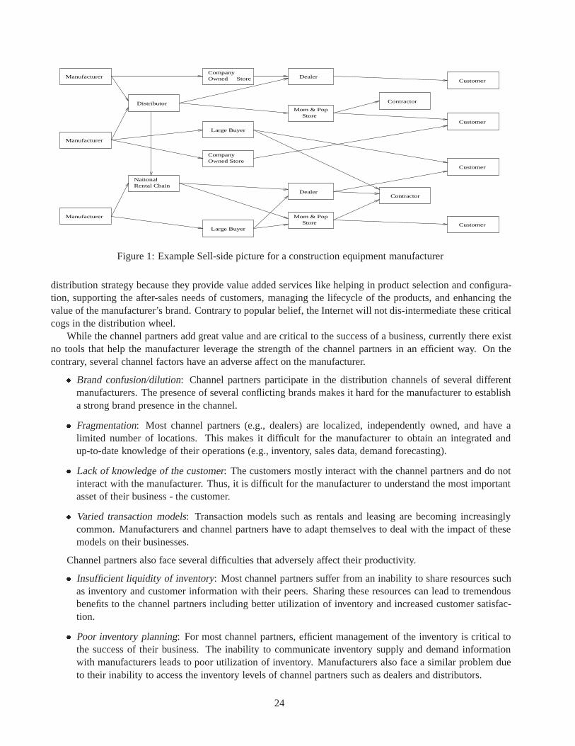
OwnedManufacturer StoreCompany
Distributor
NationalRental Chain
Large Buyer
CompanyOwned Store
Large Buyer
Manufacturer
Manufacturer
Dealer
StoreMom & Pop
Dealer
Mom & PopStore
Contractor
Contractor
Customer
Customer
Customer
Customer
Figure 1: Example Sell-side picture for a construction equipment manufacturer
distribution strategy because they provide value added services like helping in product selection and configura-tion, supporting the after-sales needs of customers, managing the lifecycle of the products, and enhancing thevalue of the manufacturer’s brand. Contrary to popular belief, the Internet will not dis-intermediate these criticalcogs in the distribution wheel.
While the channel partners add great value and are critical to the success of a business, currently there existno tools that help the manufacturer leverage the strength of the channel partners in an efficient way. On thecontrary, several channel factors have an adverse affect on the manufacturer.
� Brand confusion/dilution: Channel partners participate in the distribution channels of several differentmanufacturers. The presence of several conflicting brands makes it hard for the manufacturer to establisha strong brand presence in the channel.
� Fragmentation: Most channel partners (e.g., dealers) are localized, independently owned, and have alimited number of locations. This makes it difficult for the manufacturer to obtain an integrated andup-to-date knowledge of their operations (e.g., inventory, sales data, demand forecasting).
� Lack of knowledge of the customer: The customers mostly interact with the channel partners and do notinteract with the manufacturer. Thus, it is difficult for the manufacturer to understand the most importantasset of their business - the customer.
� Varied transaction models: Transaction models such as rentals and leasing are becoming increasinglycommon. Manufacturers and channel partners have to adapt themselves to deal with the impact of thesemodels on their businesses.
Channel partners also face several difficulties that adversely affect their productivity.
� Insufficient liquidity of inventory: Most channel partners suffer from an inability to share resources suchas inventory and customer information with their peers. Sharing these resources can lead to tremendousbenefits to the channel partners including better utilization of inventory and increased customer satisfac-tion.
� Poor inventory planning: For most channel partners, efficient management of the inventory is critical tothe success of their business. The inability to communicate inventory supply and demand informationwith manufacturers leads to poor utilization of inventory. Manufacturers also face a similar problem dueto their inability to access the inventory levels of channel partners such as dealers and distributors.
24

Finally, from the perspective of the customers, a complex distribution channel consisting of a variety ofindependent, autonomous channel partners ultimately leads to confusion and poor buying experience.
� No single point of contact for after-sale needs: Ideally, customers should be only aware of a single entityfor their after-sales and service needs. Fragmented and loosely coupled distribution channel can lead tomultiple points of contact for these needs leading to customer confusion.
� No single point of contact for related product needs: In order to get a seamless buying experience, cus-tomers should not have to deal with multiple sellers to obtain related products and services. A distributionchannel that does not allow for sharing of resources and information among the partners will deprive thecustomers of their preferred “single point of contact” customer experience.
� No unified account management: Large national customers would like to have a single account that worksacross channel members belonging to different geographic locations with portable credit across thesemembers.
Tavant has built a sell-side commerce platform to specifically address the above needs by enabling manufac-turers as well as the channel partners to better manage the channel by improving communication between eachother and with the end-customers. Tavant’s solution gives manufacturers more visibility into the channel, en-ables them to extend the reach of their brands, and allows them to participate in downstream revenues1 . Channelpartners, in turn, gets a solution that gives them access to the manufacturers resources such as inventory, allowsthem to participate in multiple networks where they can cross-sell complementary inventory to customers, andlets them manage their existing business relationships more efficiently.
As mentioned earlier, current sell-side solutions are focused on enabling manufacturers to establish directrelationships with customers. These attempts have not been well-received by the channel partners and havecreated channel conflict, resulting in limited success. Tavant’s solution, on the other hand, is architected toaddress the challenges in integrating complex distribution channels and is designed to empower the channelpartners.
In Section 2, we present the Tavant Platformand provide an overview of a few important components of theplatform. In Section 3, we discuss an important feature of the platform that allows channel members2 to tailortheir experience based on their individual preferences. We discuss the unique time-based transaction componentin Section 4 and conclude in Section 5.
2 Tavant Platform
One of the challenges in building a channel integration platform is to develop a core set of concepts - i.e. amodel, that supports the diverse needs of the channel and is able to adapt to its evolving needs. The Tavantplatform consists of a flexible model and a variety of features to integrate and manage channel partners. Theseinclude:
� Network and Website Management: Allows manufacturers to create networks to aggregate the variouspartners in their sell-side channel and their assets (such as inventory) into a logical unit. Channel memberscan create customized websites which act as access points into the networks.
� Custom Channel Views: Offers customized views of the various types of channel members to otherchannel members. These views bring true transparency and integrity to a fragmented distribution channel.We list a few examples below and mention some of the benefits they bring to the channel members :
1Revenues generated after initial sale through services, parts sale, etc.2All the players in a channel - including the manufacturer, channel partners, and customers.
25

ERP,...
Websites
Manufacturer A Dealer B Customer C Dealer D Customer E Dealer F Manufacturer G
Manufacturer A’s Network (N1) Manufacturer G’s Network (N2)
Platform Services :Catalog Mgmt, Order Mgmt, Pricing,Channel Mgmt, Inventory Mgmt,...
Horizontal Services :Internationalization, Security,Database Access
ChannelConfigurator
Time-basedTransactions
End Applications :Rentals, Used/New Product Sales, Services, etc.
MF-A.com DL-B.com DL-F.com MF-G.comDL-D.com
XML C
onne
ctors External
Systems
DealerAutomation,
Figure 2: Tavant platform - Application Architecture
– M2D : Manufacturer’s view of Dealers. Gives the manufacturer access to the dealers’ inventory, andsales and rental data. This helps them in demand forecasting and planning production operations.
– D2M : Dealer’s view of Manufacturers. Helps the dealer to access product information and produc-tion capacities of the manufacturers which can help them improve their inventory utilization.
– D2D : Dealer’s view of other Dealers. Enables the dealer to share inventory with other dealersto increase their inventory liquidity, and also enables them to communicate product and customerinformation with other dealers in an efficient way.
– C2D : Customer’s view of Dealer. Provides the customer with commerce facilities (product search,order management etc.) on a dealer’s website. If the dealer shares inventory of other channel mem-bers, the customer can get a wider selection of similar and related products on the same dealer’s site.The customer can thus have a single point of contact for most of his product needs.
� Micro-channels : Channel partners such as dealers can create sub-networks consisting of partners thatdon’t belong to the original network. For example, a dealer can create a micro-channel consisting of thevarious independent retail stores that he deals with. The sub-network adds utility to and derives benefitfrom the main network. The ability of channel partners to create micro-channels helps the networks andsub-networks expand their scope in an easy and scalable way.
� Multi-network membership : A channel partner can belong to multiple networks. This provides greatervisibility to the partner, brings more customers and revenue opportunities, and increases the number ofmembers whom they can partner with.
� Integrated login : A customer in a network can use their login, account, and credit in all the websites ofthe various members of the network.
� Multiple transaction models : Supports various kinds of transactions that happen in the channel such asNew Product Sales, Used Product Sales, Rentals, and Services.
The Tavant platform is offered as a hosted service (ASP) to its customers. Figure 2 illustrates the applicationarchitecture of the platform. It consists of a variety of core sell-side e-commerce services like Catalog Manage-ment, Product Search, Pricing, and Order Management. These commerce services can be integrated to create
26

specific end applications like Rentals, New/Used Product Sales, and Services. The Order Managementservicesupports multiple kinds of workflows through which an order can be submitted. These include Instant, in whichthe order is completed in real-time and in sync with the user’s action, Request-Response-Confirm, in which theuser requests for price, availability or other information from the supplier and then confirms the order when hegets a response, and Request for Quotes (RFQ), in which a user sends a request to many suppliers and acceptsthe most favorable quote(s). Another platform service, namely the Channel Managementservice, supports mostof the channel integration features described earlier. The platform also provides XML based connectors to in-tegrate with external systems such as dealer automation software, ERP applications and legacy systems. Thisallows channel members to continue to use their existing systems for their regular operations.
The platform also contains two core components, Channel Configuratorand Time-based Transactions, thatprovide infrastructure for the various platform services. Channel Configuratorprovides a framework to supportthe extensive customization needs of the various channel integration features. The Time-based Transactionscomponent provides services to support time-based transaction models such as rentals and service-scheduling(e.g., scheduling repairs and inspections). We discuss these components in the next two sections.
3 Channel Configurator
As discussed earlier, the requirements of sell-side channels are varied and dynamic. Hence, the channel inte-gration features supported by the platform need to be highly configurable. The Channel Configurator providesa framework to address these configurability requirements. A website that is created to access a network cancustomize the site along various dimensions such as
� Data : Select from available product categories; filter products based on attributes such as manufacturer.
� Operations : Choose from available applications such as Sales (New/Used), Rentals; choose from variousworkflow models such as Instant, Request-Response-Confirm, and RFQ.
� Presentation (Look-and-Feel): Choose from a set of UI styles; pick branding, logo, and colors.
The Channel Configurator also provides a mechanism for channel members to (a) specify the parts of theirdata they wish to expose to other members, and (b) to specify, from the parts exposed by other members, theparts of data they wish to access. This allows the channel members to retain the security and confidentiality oftheir data, and at the same time allow for greater channel transparency and information exchange between themembers. This mechanism forms an important part of the Custom Channel Views functionality described insection 2.
We now illustrate some of the configurability choices with an example based on figure 2. Manufacturers Aand G have created networks - Network N1 and Network N2 respectively, to integrate their sell-side channel,and created websites MF-A.com and MF-G.com to access the network. Other channel partners - Dealer B,Dealer D and Dealer F, have also created websites (namely, DL-B.com, DL-D.com, and DL-F.com) to accessthe networks. Dealer D carries products manufactured by both A and G and is a member of both networks. Asan example of selecting what data to expose, dealers B and D may not share inventory with each other, but D canshare inventory with both A and G. To preserve their branding, A can filter the products listed on MF-A.com tothe product categories relevant to A, and within those categories restrict them to only those manufactured by A.Hence, when a user visits MF-A.com, he can see products carried by D that are manufactured by A but cannotsee products of D that are manufactured by G. As an example of an operation filter, manufacturer A who mayonly sell new products to its customers, can choose to expose only the new sales application on MF-A.com. Onthe other hand, Dealer D may sell and rent products, and hence can decide to expose new sales, used sales, andrentals on DL-D.com. As another operation customization, A can enable RFQ’son MF-A.com to help customers
27

request quotes from multiple dealers - dealers B and D for example. On the other hand, D may have no need forsuch a functionality, and hence disable RFQ’son DL-D.com.
One of the important challenges in architecting the Channel Configurator component is to support thesehigh-configurability requirements in a single platform. Further, the interplay between the various functionalitiesand the variety of configuration knobs also pose special challenges - for example, supporting keyword basedproduct search on a large number of channel websites with varying data filters on each website. The ChannelConfigurator has been architected with the aim of enabling our solution for “configurability without customprogramming”. This approach, unlike many ERP solutions that require programming and huge deploymentcosts for client-side customization, allows for easy and rapid customization of Tavant’s solution.
4 Time-based Transactions
Renting is a common transaction model that occurs frequently in the real world. One of the unique featuresof the Tavant platform is its support for rentals and other time-based transactions such as service scheduling.With it, the platform can support networks consisting of rental stores, and dealers and manufacturers of rentalproducts.
Most of the current e-commerce systems only enable buy/sell transactions and these systems do not havea fundamental notion of time. The few existing solutions that deal with the concept of time are very domain-specific (e.g., SABRE platform in the travel industry). We now look at some of the necessary and useful servicesneeded to support time-based transactions in an e-commerce system.
� Availability : The system has to check whether the required quantity of the resource is available for therequested time period. The availability computation unit has to check all existing orders and ensure thatthe requested quantity is available at all times during the requested time period. The challenge is indeveloping an efficient method to answer this complex query with low response time.
� Alternatives : If the resource is not available, the system can suggest ”close” alternatives. The challenge isto determine what is ”close” - partial quantity, a different time-period, a different provider of that resourceor a similar resource.
� Complex transaction requests : A customer may want certain units of a resource at the ”earliest possibletime”.
� Dynamic pricing : Pricing could be based not just on when the transaction occurs (weekends/weekdays,holidays, seasons etc.), but also on duration of the transaction.
The Time-based Transactionscomponent incorporates the concept of time in a fundamental way and isdesigned to cater to the above challenges.
5 Conclusion
Integrating the sell-side channel of a business greatly improves the efficiency and economic value of the chan-nel. The Tavant platform provides a solution to address the integration needs of channels that involve variousintermediaries (such as dealers, large buyers, etc.). The platform contains a core set of concepts to model thiscomplex problem, and provides features such as Network and Website creation, and Custom Channel Views tointegrate the channel and improve its transparency. The solution needs extensive configurability to support thediverse needs of the channel, which creates significant engineering challenges. The Channel Configurator isa configuration framework that is designed to handle these challenges. With its support for time-based trans-actions, the Tavant platform has the unique ability to integrate sell-side channels involving rental stores, anddealers and manufacturers of rental products.
28

Definition, Execution, Analysis, and Optimization of CompositeE-Services
Fabio Casati and Ming-Chien ShanHewlett-Packard Laboratories1501 Page Mill Road, 1U-4
Palo Alto, CA, 94304casati,[email protected]
Abstract
The Internet is becoming the mean through which services are delivered to businesses and customers.Standard bodies as well as individual software vendors are rushing to define languages, protocols, andtools that support the development and deployment of e-services. The shift to the e-services paradigmprovides the opportunity and the need for defining value-added,composite services by orchestratingother basic or composite ones. In this paper we present our efforts towards the development of a servicecomposition facility. We first illustrate the characteristics of composite services, and then describe theservice composition model and language we have developed, by reusing concepts from the workflowresearch community where possible and extending them when needed. We next introduce the prototypeimplementation of a composite service engine, and we conclude the paper by detailing our work inprogress on composite service analysis and optimization.
1 Introduction
The next chapter of the Internet story is about the mass proliferation of e-services. Indeed, more and morecompanies are rushing to provide all sorts of services on the Web, ranging from ”traditional” on-line travelreservations and directory services to real-time traffic reports and even outsourcing of entire business functionsof an organization. As Web technologies continue to improve, allowing for smaller and more powerful webservers, and as more and more appliances become web-enabled, the number and type of services that can bemade available through the Internet is likely to increase at an even higher rate.
A few years ago, HP decided to invest heavily in the e-service area. Efforts were focused on both the devel-opment of specific e-services as well as infrastructuresfor supporting the design, development, and delivery ofe-services. In particular, one of the main results of this effort has been the development of an e-services platformcalled e-speak[6]. E-Services Platforms (ESPs) are software tools that facilitate users in deploying applications(typically Java objects) as e-services and in securely delivering the services offered by these applications toauthorized users.
Copyright 2001 IEEE. Personal use of this material is permitted. However, permission to reprint/republish this material for ad-vertising or promotional purposes or for creating new collective works for resale or redistribution to servers or lists, or to reuse anycopyrighted component of this work in other works must be obtained from the IEEE.Bulletin of the IEEE Computer Society Technical Committee on Data Engineering
29

ESPs allow service provider to registerservice descriptions and to advertisethem in web directories (suchas LDAP or UDDI directories). Service providers are also offered features to monitor and manageserviceexecutions. Once a service has been registered and possibly advertised, it can be discovered by customers.Typically, customers query the service repository associated with the ESP or web directories for services ofinterest. As the result of the query, clients get references (handles) to e-services that can fulfill their needs.Then, clients can use these references to get more information about the services or the service providers, orthey can immediately invoke a service. Access to a service is restricted to authorized users, according to thesecurity features provided by the platform.
The e-service economics create the business opportunity for providing value-added, integrated services,delivered by composing existing e-services, possibly offered by different providers. For instance, an eMovecomposite service could support customers that need to relocate, by composing truck rental, furniture shipments,address change notification, and airline reservation services, according to the customer’s requirements [1].
Service composition(or orchestration) is seen by many ESP vendors, (including HP) as a strategic area thatcan provide a competitive advantage within the ESP arena. In this paper, we provide an overview of our workon service composition, both with e-speak and with ESPs in general, and then we give pointers to our technicalreports for details. We begin by describing our work on the service composition model and present the prototypewe have developed. Then, we introduce our work in progress on composite service analysis and optimization.
2 Service composition model and language
A composite service is similar to a workflow. In fact, it represents a complex activity specified by composingother basic or complex activities. Like in workflows, a composite service definition must include the specifica-tion of the component services and their execution dependencies, as well as their input and output parameters.However, composite services have several characteristics that makes them different from workflows (see [3] fora detailed discussion):
� Services in ESPs are typically more complex than workflow activities (that are often modeled as “single-function” black boxes). In particular, in most e-services model (including e-speak) a service can offerseveral operations to be invoked. For instance, a car rental service may offer operations to browseavailablecars, and then booka car or cancela reservation. Interacting with an e-service requires operations to beperformed at the service level (e.g., search and authentication) and operations to be performed at themethod level (e.g., method invocations). These aspects of e-services must be taken into account by aservice composition model. In addition, services typically interact by exchanging XML documents, whileXML support is very limited in “traditional” workflow models and systems.
� Composite services need to be more adaptive and dynamic, consistently with the adaptive and dynamiccharacteristics of the e-services environment, where new services are created every day.
� Security is a key issue, since services do not reside within the protected intranet, but can be anywhere onthe Internet. Hence, mechanisms to specify and enforce security requirements must be supported.
In order to meet the above-mentioned requirements, we have designed a Service Composition Model (SCM),by reusing workflow concepts where possible and extending them when needed. We next present SCM and thecorresponding language, called Composite Service Description Language(CSDL). Details on the model andlanguage are provided in [2, 3]. Like most workflow models (see, e.g., [5]), CSDL describes the compositionby means of a directed graph, whose nodes represent interactions with e-services (for instance to authenticate orinvoke service methods) and arcs define execution dependencies among services. Special nodes are provided todenote the starting and ending points of the composite service, or to route the execution flow. Each composite
30

service has a set of local data items, that can be used to exchange data with the invoked services and to makerouting decisions.
SCM has a two-level business process model, that distinguishes between invocation of servicesand of meth-odswithin a service, represented by service and method nodes, respectively. Service nodes define service-levelparameters, such as the service selection criteria (e.g., a car rental service available in Como, Italy) and the dig-ital certificate to be sent to the service upon invocation, while method nodes model the invocation of a specificoperation within a service. In addition, since clients may need to invoke several operations on the same service,SCM allows the designer to represent, within a service node, the flow of method invocations to be performedon a service. For instance, in order to access a car rental service, we may specify that we first browseand getdetails about available cars and their prices, and then booka car if the price is below a certain limit.
Methodnodes define the methods to be invoked on a service, as well as the input and output data. Thename of the method to be invoked can be statically specified, or it can be dynamically taken from the value ofa composite service data item. To support the invocation of e-services that exchange information through XMLdocuments (and in particular to model invocation of services defined according XML-based B2B standards,such as RosettaNet), designers can associate XML templatesto method invocations. XML templates are XMLdocuments in which some parts are parametric and refer to data items of the composite service. When a methodis invoked, these parameters are replaced with actual values, and the resulting XML document is sent to theservice. If the service output is also an XML document, then it is possible to extract the values of elements orattributes of interest and insert them into data items of the composite service. This is done by defining, for eachdata item to be updated by the method invocation, an XQL query that processes the output document and obtainsa scalar value. Details are provided in [3].
In order to manage authentications, SCM provides a flexible and easy-to-use mechanism for handling cer-tificates. In fact, the definition of a composite service includes information about the certificates to be used wheninvoking services within the flow, in case the ESP and the invoked e-service support, or even require, the use ofdigital certificates, as in e-speak. By default, services are invoked with the privileges (i.e., the certificate) of thecomposite service user. However, the designer may specify that services should be invoked with the privilegesof the composite service designer, or with the privileges specified by the content of a data item (for instance,the certificate to be used may have been received as output parameter during a previous invocation). In addition,defaults at the composite service level can be overridden at the service node level.
To manage and even take advantage of the frequent changes in today’s business environment, compositeservices need to be adaptive, i.e., capable of adjusting themselves to changes with minimal or no manual inter-vention. SCM includes several constructs that allow services to be adaptive: These are dynamic conversationselection, multiservice nodes, and generic nodes(see [4]).
Dynamic conversation selection makes it practically possible to use dynamically discovered e-services. Infact, one of the most advertised advantages of e-services is the ability of dynamically selecting the best availableservice. Facilities for dynamic selection are also provided in CSDL. However, since different providers mayoffer different interfaces for the same type of service, if the conversation (i.e., the flow of method invocations) isstatically defined at composite service definition time, then the statically defined conversation could be inconsis-tent with the interface provided by the dynamically selected service. By using dynamic conversation selection,the designer is not required to secify the conversation at definition time, but can instead specify that the con-versation should be selected at run time, based on the service returned by the execution of the service selectionquery. Conversation selection is performed by maintaining a repository of conversations. The designer specifieswithin a service node that the conversation should be dynamically selected from a repository. At service invo-cation time, the system will load from the repository the conversation that corresponds to the selected service.Note that if dynamic conversation selection is used, then the designer should make sure that the service selectionquery restricts the search to those services for which there is an entry in the conversation repository, otherwisean exception is raised.
31

Multiservicenodes model multiple, parallel activations of the same service. For instance, a composite servicemay need to invoke several car rental services to get prices and availability. The number of nodes to be activatedis determined at run time, based either on the number of service providers able to offer a given service, or onthe number of elements in a composite service data item of type list. For instance, in order to rent a car, we maywant to check the prices of all car rental companies available at a given location. As another example, assumethat a composite service must check the credit history of a group of customers. The number of service nodes tobe instantiated must be equal to the number of customers, and each node will focus on one customer.
Genericnodes enable the parallel activations of multiple instances of different services. Unlike ordinaryservice nodes, which are either statically bound to a service or to a service selection query, generic nodes areplaceholders. They only include a configuration parameter that can be set with a list of actual service nodeseither at composite service instantiation time (through the composite service input parameters) or at runtime.
While adaptive models reduce the need for human intervention in maintaining composite service definitions,there are still cases in which these definitions need to be modified, or in which actions need to be taken onrunning instances to modify their course, for instance to handle unexpected situations or to incorporate newbusiness policies. SCM allows two types of service process modifications: ad-hoc and bulk changes [3].
Ad-hoc changesare modifications applied to a single running service process instance. They are used tomanage exceptional situations that are not expected to occur again. Bulk changesrefer to modifications col-lectively applied to a subset (or to all) the running instances of a composite service. Modifications to runninginstances are specified by a set of migration rules, that define the flow to which each instance should migrate,i.e, specify the future behavior of running instances. A migration rule identifies a subset of the running instancesof a given composite service as well as the target service definition. They have the form IF <condition>THEN MIGRATE TO <flow def>. The condition is boolean expression that identifies a subset of the run-ning instances, while <flow def> denotes the destination flow. The rules must define a partition over the setof running instances. Instances that do not satisfy any rule condition are not migrated.
3 Prototype implementation
Service composition facilities can be offered in several different ways: as a development environment targetedto the enterprise IT personnel, as an e-service itself, or as a functionality integrated with the ESP. We decided tostructure the composition facility as an e-service (or, rather, a meta-service, since it is a service for developinge-services), since in this way it can be advertised, discovered, delivered, managed, and protected by end-to-end security analogously to any other e-service, thereby exploiting all the advantages and features providedby the ESP. In particular, service composition functionality can be offered to other businesses and customers,thereby relieving them from the need of maintaining a composition system that may be onerous to buy, install,and operate. In addition, with this approach it is easier to provide the same functionality on top of ESPs fromdifferent vendors, by making (relatively) simple modifications to the prototype.
In the following we will refer to this service composition facility as Composition E-Service, or simply CES.The prototype is built on top of e-speak and HP Process Manager (a commercial workflow engine). CES hasa front-end that accepts invocations of CES methods from service providers, in order to register, modify, anddelete composite services. For instance, providers can register a composite services by invoking the registermethod of the CES and sending the CSDL description of the composite service as parameter (see Figure 1). TheCES then translates CSDL into the language of the selected workflow engine, inserting the appropriate “helper”nodes and data items that enable the correct implementation of the CSDL semantics.
A gatewayenables the interaction between the workflow engine and the ESP. All the nodes defined in thegenerated workflow are assigned to the gateway, that invokes the appropriate operations on the ESP or on theselected service, thereby performing the appropriate data mappings and implementing CSDL semantics thatcould not be supported by the workflow engine.
32

E-Services Platform
1:Register composite
service�������
������ ������
2:Create process
3:Register service in e-speak
'DWD�FROOHFWL RQ�,,
%LOOLQ J�,,
$LU OLQH �VK LSPHQ W
6WRU DJH�VSDFH�U HQWDO
7U XFN�UHQW DO
5DLOZ D\�VK LSPHQ W
$LUOLQH�UHVHUYDWLRQ H0RYH�OHYHO�,
H0RYH�OHYHO�,,Start Node Com plete
Check credit
Wheel del ivery
Restaurant selecti on
Check passed?
And Join Credi t card
yes
Abort
CSDL
Custom News
��������������������
Service Provider
Figure 1: Composite service registration (components of the prototype are shaded).
Once the translation has been performed and the process deployed on the workflow engine, the CES makesthe composite service available as an e-service, by registering it with the ESP. The CES also registers itself asbeing the handler of the service. From this moment, the (composite) service can be searched and invoked justlike any other basic service.
When a client invokes a service on the ESP and the service is composite, the ESP calls the CES that,in turn, activates the corresponding process in the workflow system. The workflow engine will then run theprocess by scheduling nodes in the workflow and assigning them to the gateway. In particular, the gatewayreceives indication of what to do by the workflow engine as part of the node data items that provide (a) contextinformation about the service on which method calls have to be made and (b) the value of the parameters to bepassed as part of the method invocation. When the workflow completes, the CES returns the service results tothe ESP, which transfers them to the invoking client.
4 Service composition analysis
This section describes our work in progress in the service composition area, focused on the analysis and opti-mization of composite service executions. In order to attract and retain customers as well as business partners,organizations need to provide (composite) services with a high, predictable quality. From a service compositionperspective, this has several implications: for instance, the composite services should be correctly designed, theirexecution should be supported by a system that can meet the workload requirements, and the invoked servicesshould be able to perform the work with the appropriate quality. To support providers in offering services thathave a high and predictable quality, we are working towards the development of a comprehensive, customiz-able, and ready-to-go business process intelligence (BPI) solution. This solution enables business and IT usersto extract knowledge from composite service execution logs and to be alerted of critical situations or foreseenquality of service degradations. In addition, the BPI tool suite is capable of dynamically affecting compositeservice execution (with the limitations and constraints allowed by the service designer). The basic idea behindour work, started in the workflow management domain and then extended to composite services, consists in an-alyzing service execution logs with OLAP and data mining technologies, in order to enable interactive analysisand to extract ”hidden” information.
The overall BPI architecture is shown in Figure 2. Data are periodically extracted from the CES logs andloaded into a warehouse by Extract, Transfer, and Load (ETL) scripts. Having a data warehouse of workflow datais in itself very useful, since it enables OLAP and multidimensional analysis of audit logs, possibly including
33

���
���������� ���������
�������
������������
������������������������� �
����������������������������������
���
������������
Figure 2: Overall architecture of the Business Process Intelligence application.
aggregation of data coming from different CESs. The BPI engine then processes the content of the warehouseand produces:
� Aggregated data and statistical information about the performance and quality of composite services aswell as of individual, component services.
� Explanation of execution behaviors, such as the activation of given paths in the flow, the use of a specificservice, the occurrence of an event, or the (in)ability to meet service level agreements.
� Prediction models, i.e., information that can be used to predict the behavior and performances of a com-posite service instance, of the invoked services, and of the CES.
The initial tests, conducted on internal administrative services for HP employees, have given promisingresults, identifying bottlenecks and causes of delays in service executions. We now plan to extend this work intoa product to be coupled with the HP e-speak and HP Process Manager composition tools.
References
[1] F. Casati, S. Ilnicki, L. Jin, V. Krishnamoorthy, M. Shan. e-Flow: a platform for developing and managing compositee-services. In Proceedings of the Aiworc’00, Buffalo, NY, USA, June 2000.
[2] F. Casati, S. Ilnicki, L. Jin, M. Shan. eFlow: An open, flexible, and configurable system for service composition. InProceedings of Wecwis’00, Milpitas, CA, USA, June 2000.
[3] F. Casati, S. Sayal, M. Shan. Developing e-services for composing e-services. 2001. Submitted for publication andavailable on request.
[4] F. Casati and M. Shan. Dynamic and adaptive composition of e-services. Information Systems. To appear.
[5] D. Georgakopoulos, M. Hornick, A. Sheth. An overview of workflow management: From process modeling to work-flow automation infrastructure. Distributed and Parallel Databases, 3(2):119–153, April 1995.
[6] Hewlett-Packard. e-speak: Architectural Specifications. Available from www.e-speak.hp.org, June 2000.
34

BizTalk Server 2000 Business Process Orchestration
Bimal Mehta, Marc Levy, Greg Meredith Tony Andrews, Brian Beckman, Johannes Klein, Amit MitalMicrosoft Corporation
One Microsoft Way, Redmond, WA 98052
Abstract
BizTalk Server 2000 unites, in a single product, enterprise application integration (EAI), business-to-businessintegration, and the advanced BizTalk Orchestration technology to allow developers, IT professionals, and busi-ness analysts to easily build dynamic business processes that span applications, platforms, and businesses overthe Internet. BizTalk Server 2000 is a high-performance platform for integrating message-based applications inthe Internet providing support for transport normalization, message transformation and business process man-agement. BizTalk Orchestration, BizTalk’s business process management component, is deeply integrated withMicrosoft SQL Server and COM+ for addressing the needs of automating mission critical business processes.Its unique compensation and exception handling features provide additional support to address difficult reallife business problems. BizTalk Orchestration introduces a novel exception handling and compensation frame-work. The article will explore the different areas addressed by the BizTalk product, in particular its support foropen-nested transactions and its unique compensation and exception framework for handling errors in long-livedbusiness transactions.
1 Introduction
BizTalk Server 2000 unites, in a single product, enterprise application integration (EAI), business-to-businessintegration, and the advanced BizTalk Orchestration technology to allow developers, IT professionals, and busi-ness analysts to easily build dynamic business processes that span applications, platforms, and businesses overthe Internet.
Business Process Management.The BizTalk Server infrastructure helps integrate, manage, and automatedynamic business processes by exchanging business documents among applications, and within or across orga-nizational boundaries. With all the tools that companies need for business process orchestration, BizTalk Serverhelps building processes that span not only applications, but also businesses, over the Internet. Graphical toolsmake it easy for analysts and developers to model and implement these processes.
Integrate Applications and Business Partners.BizTalk Server 2000 makes it easy to integrate applicationsand businesses together with a host of rich graphical tools for building Extensible Markup Language (XML)schema, performing schema transformation, establishing trading partner relationships over the Internet, andtracking and analyzing data and documents that are exchanged. With XML and standard Internet transport and
Copyright 2001 IEEE. Personal use of this material is permitted. However, permission to reprint/republish this material for ad-vertising or promotional purposes or for creating new collective works for resale or redistribution to servers or lists, or to reuse anycopyrighted component of this work in other works must be obtained from the IEEE.Bulletin of the IEEE Computer Society Technical Committee on Data Engineering
35

security technologies support, BizTalk Server 2000 extends the features of traditional e-commerce and electronicdata interchange (EDI) to entire e-commerce communities.
Interoperability Using Public Standards. With extensive support for public standards and specifications,such as XML, EDI, Hypertext Transfer Protocol (HTTP), and Simple Mail Transfer Protocol (SMTP), andsecurity standards like public key encryption, digital signatures, and encryption, BizTalk Server 2000 ensuresthe highest level of interoperability and security for applications and business partners.
2 BizTalk Server Architecture
BizTalk server is built for performance, reliability and scalability. BizTalk server is targeted to process hundredsof business documents per second, even on small sized configurations. Microsoft SQL Server is used to storeall business documents. COM+ application servers host and execute long-lived business processes. Clusteringand fail-over support provided by Windows2000 and SQL Server ensure a very high level of reliability andavailability [3].
Business Process Orchestration
Message Transformation
Transport Normalization
Figure 1: BizTalk Processing Layers.
BizTalk server manages trading relationships between business partners. We can distinguish three differentlayers within BizTalk Server: transport normalization, message transformation and business process manage-ment. At the messaging layer trading relationships are described by a set of transport protocols over which toexchange business documents and a set of rules for encrypting, parsing and validating documents exchanged.Once a document has been received and passed all processing steps it is forwarded by BizTalk Server to asubscribing application, business process or remote trading partner. Transmitting a document may require thedocument to be transformed into one understood by the receiving partner, signed, encrypted and sent over atransport with the correct set of delivery guarantees.
BizTalk Server supports the protocols and message formats defined in BizTalk Framework 2.0 [3] to reliablyexchange business documents over the Internet.
SharedQueue Tracking
Database
Message Handlers
Figure 2: BizTalk Server Group.
36

BizTalk Server allows the configuration of groups targeted towards a particular application. Each group hasits own set of resources. Each group has a database acting as shared queue. A second database is used forrecording information on the progress of messages.
Message handlers access the shared queue for storing and retrieving messages. For scale-out message han-dlers are spread across nodes in a cluster. Processing nodes can be added or removed depending on the load ofthe overall system.
All groups share a common configuration database. Different groups may be used for different types ofwork. An application may use one group for low-latency message processing jobs while routing bulk processingjobs to a different group to ensure quality of service.
All message processing is done within a transaction. Messages received are stored in the shared queue beforeforwarding them to a trading partner, application or business process. Business may use the message store forauditing and optionally mining the exchange of documents between business partners.
BizTalk Orchestration layered on BizTalk messaging has been built to handle transactional, enterprise-scalebusiness processes. BizTalk Orchestration processes individual steps in a business process within a transaction.It stores, i.e. “dehydrates”, the state of a business process in the database. BizTalk Orchestration makes use ofCOM+ transaction services to ensure consistency and recoverability of the overall business pro cess.
3 BizTalk Orchestration Programming Model
BizTalk Orchestration is BizTalk Server’s business process management component. BizTalk Orchestrationuses the underlying transformation and messaging capabilities of BizTalk Server for exchanging documentswith business partners and applications. BizTalk Orchestration supports the execution of long-lived businessprocesses.
BizTalk Orchestration’s programming model is based on the notion of exchanging business documents, i.e.messages between autonomous agents. All actions are expressed in terms of messages received and messagessent. Messages are constructed by specifying how to populate fields with data from already existing messages.Messages once created are immutable documents.
The message centric approach adopted by BizTalk Orchestration [1] ensures that business processes arecompositional. It reflects the true nature of business processes in the Internet which do not allow for shared statebut have to depend on all information be communicated. Individual participants publish their parts of a businesscontract. It describes what documents to exchange and the order in which they have to be submitted.
Figure 3 shows an interaction diagram, which describes interactions, i.e. the exchange of business doc-uments, in a procurement process. BizTalk Orchestration defines an XML based language, XLANG, whichcaptures those interactions in a document. XLANG programs capture the dynamic and static properties of mes-sages exchanges between business partners. Dynamic properties define sequencing rules, guarding the exchangeof messages. Static properties define ports, i.e. transport endpoints, and how they are connecting participantscooperating in a business process.
BizTalk supports all the usual control flow constructs such as sequence, branching and loops. For connectingthe various participants BizTalk ports can be bound to a variety of transport protocols such as BizTalk messaging,COM, and MSMQ.
BizTalk is unique in its support for passing binding information at runtime. This is a very common techniqueused by Web services, which pass URIs as referrals, or redirects to partners. It allows business processes todynamically connect and locate participants in a business process upon receipt of an e-mail address or uponreceipt of an HTTP URL. Ariba’s cXML protocol [5] is a good example for the importance of such a techniquewhen connecting buyers and suppliers in a market place. Reference passing is key to dynamically establishingmulti-party relationships.
37

Customer Supplier Shipper
PO
PO Confirmation
Invoice
Payment
Ship Order
ETA
Figure 3: Procurement Scenario.
In the Internet service descriptions and binding information will be located using directory services as pro-posed by Microsoft, IBM and Ariba [4] and service descriptions as described in WSDL, a joint Microsoft andIBM proposal for publishing web services [4].
4 Transactions, Exceptions, and Compensations
BizTalk facilitates management of trading relationships in the Internet. In the future we expect businesses toregister with directory services and publish service descriptions for customers to automatically locate servicesand start trading. Today, setting up and debugging a trading relationship is a very time consuming and costlytask. Error handling and recovery are often manual adding additional cost to the execution of business processesand making it difficult to rely on automated processes. Support for long-lived transactions, exception handlingand compensations is key to truly enabling business process automation in the Internet.
OnFailure Compensation
Transaction
OnFailure Compensation
Transaction
OnFailure Compensation
Transaction
Figure 4: BizTalk Open Nested Transactions.
BizTalk Orchestration allows business process designers to define transaction boundaries. Transactions maybe nested. Innermost transactions are atomic database transactions [2]. The other types of transactions include a
38

variant of open nested transactions. BizTalks open nested transactions implement long-lived business processes.The state of a long-lived business process is recoverable up to the last committed ACID transaction.
In contrast to undo operations of ACID transactions compensations for long-lived open nested transactionsare supplied by the application. BizTalk Orchestration allows applications to associate a complete compensatingbusiness process with a transaction. The process defines how to compensate for the actions of the originaltransaction. BizTalk invokes compensation processes on abort of the parent transaction. Compensations areinvoked in reverse order. Compensations are executed within a new transaction context.
BizTalk Orchestration associates exception-handling processes with transactions. Exception handlers getinvoked on abort. Exception handlers are executed within a new transaction context.
The BizTalk compensation and exception-handling framework controls the visibility of messages. Messagevisibility is defined as follows. A transaction has access to all messages associated with its parent transaction.Once a transaction commits its messages are inherited by the parent and visible to all siblings.
For an aborted transaction only the messages created by its exception handling process are visible to theparent transaction. Thus an exception handling process can control what results, i.e. messages become visibleupon transaction abort.
While undo operations of ACID transactions are executed in isolation business level compensations oftendepend on the outcome of subsequent transactions and preceding compensations. Examples are purchases,which could not be returned, or money spent, which could not be recovered. The message visibility rulespresented here enable compensations to get access to this information by examining messages generated bypreviously executed transactions and compensation.
5 Concluding Remarks
BizTalk Server is a powerful platform for defining trading relationships and integrating messages based applica-tion in the Internet. Built on a mature database system and a scalable high performance transaction-processingplatform it is targeted towards the execution of mission critical business processes. With its unique support forcompensation and exception handling it gives applications additional tools to automate costly error scenarios.BizTalk’s commitment to a message based framework sets it apart from other business process frameworks andpositions it as one of the best for composing services in the Internet for executing business contracts.
References
[1 ] Milner, R. Communicating and Mobile Systems: The pi-Calculus Cambridge University Press. Cam-bridge, UK (1999).
[2 ] Gray, J. and Reuter, A. Transaction Processing: Concepts and Techniques. Morgan Kaufman Publishers,San Mateo, CA (1993).
[3 ] http://www.microsoft.com/biztalk
[4 ] http://www.uddi.org
[5 ] http://www.cxml.org
39

Workflow Mediation using VorteXML
Vassilis ChristophidesInstitute of Computer Science, FORTH,
Vassilika Vouton, P.O.Box 1385, GR 711 10,Heraklion, Greece
Richard Hull Akhil Kumar Jerome SimeonBell Laboratories, Lucent Technologies
600 Mountain Avenue,Murray Hill, NJ, USA
fhull, akhil, [email protected]
1 Introduction
The Internet and Web are revolutionizing the way companies interact with their suppliers, partners, and clients,by enabling substantial automation of the full spectrum of their business activities. In the 21st century economy,the primary form of automation will be B2B e-commerce, in which enterprises interact with each other throughentirely automated means. As an example, consider an electronic market place in a vertical industry segment,in which suppliers and buyers tie into a common IT infrastructure to exchange goods and services. This formsa supply chainin which buyers investigate possible suppliers, (b) check the terms and conditions under whichsuppliers can do business, (c) interoperate with the suppliers’ enterprise support systems, i.e., workflows, and(d) monitor ordering/purchasing for possible delays, unexpected events, react to such events, etc. This paperpresents a new framework for specifying, enacting and supervising e-services on the Web, based on XML andrules-based support for products/services descriptionand workflow mediationacross organizations.
Traditionally, WorkFlow Management Systems (WFMS) have focused on homogeneous and centrally con-trolled environments for binding people and processes within the boundary of a single organization. In thecontext of B2B e-commerce, WFMSs need to support collaborationbetween various autonomousparties, someof which may even have conflicting business goals. More precisely, they must cope with heterogeneous en-terprise support environments (e.g., through different WF systems), to model the interaction of independentpartners by abstracting the internal details of their activities (e.g., through different WF schemas), and finally tofacilitate flexible linking and monitoring of inter-enterprise processes (e.g., through different WF enactments).To address these challenges we are currently developing a workflow mediation middleware which relies on threebasic technologies: (a) the XRL workflow specification language [13, 18] for representing in XML heteroge-neous workflow schemas and enactments, (b) an XML query language [4, 5] for manipulating both complexproduct and service descriptions, and (c) the Vortex rule-based language [12, 6] that supports heuristic reasoningin order to take on-line business decisions during the workflow execution.
Recently, workflow interoperation has received considerable attention. Numerous research projects and pro-totypes have been proposed [16, 2] while basic interoperability between various vendor WFMSs has been asubject of standardization efforts by the Object Management Group (see Workflow Management Facility [9]),and the Workflow Management Coalition (see the Xf-XML binding of the WfMC Interface 4 [1]). Workflowintegration in an e-business setting has also been addressed in projects such as CrossFlow [7], WISE [14], Flow-Jet [17], InterWorkflow [10] and MOCASSIN [8]. Compared to these projects, our work introduces an explicit
Copyright 2001 IEEE. Personal use of this material is permitted. However, permission to reprint/republish this material for ad-vertising or promotional purposes or for creating new collective works for resale or redistribution to servers or lists, or to reuse anycopyrighted component of this work in other works must be obtained from the IEEE.Bulletin of the IEEE Computer Society Technical Committee on Data Engineering
40
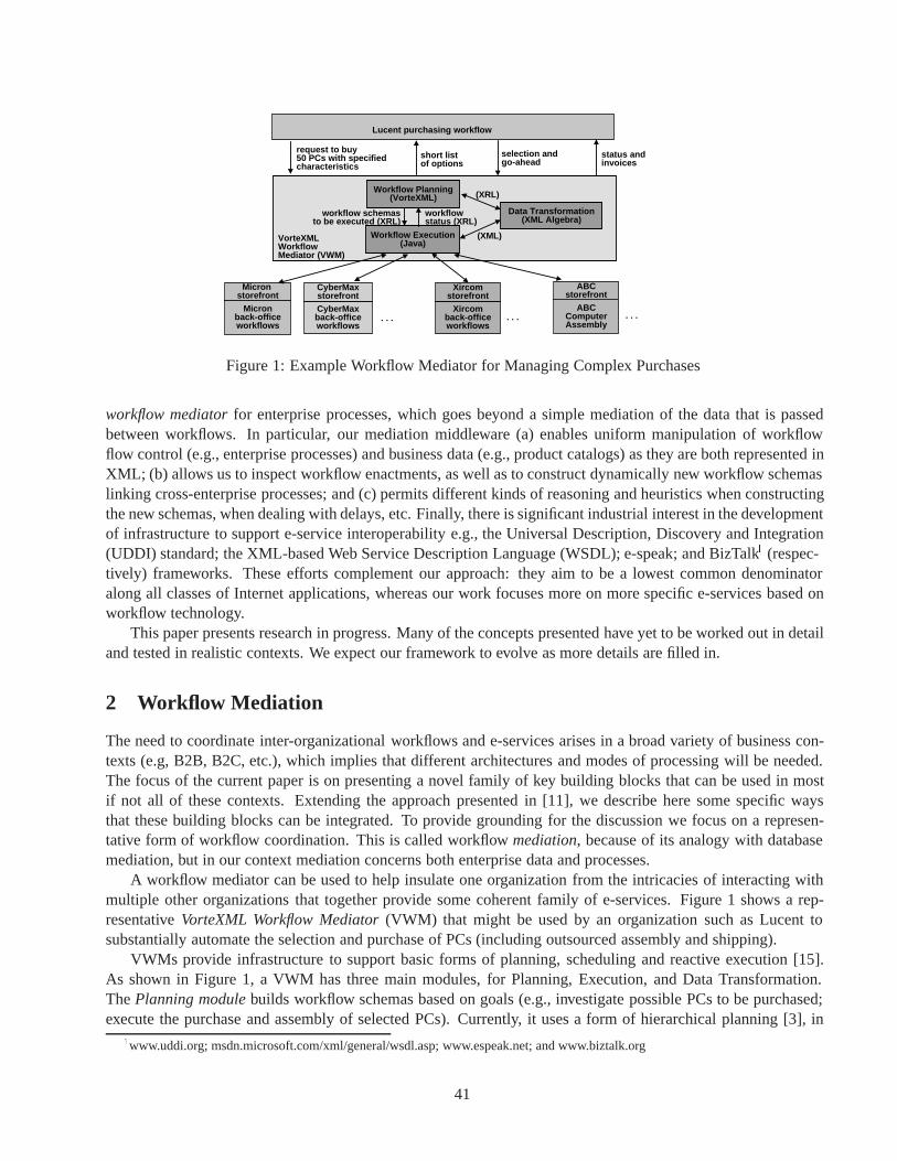
Lucent purchasing workflow
Micronback-officeworkflows
Micron storefront
CyberMaxback-officeworkflows
CyberMaxstorefront
Xircomback-officeworkflows
Xircomstorefront
ABCComputerAssembly
ABCstorefront
Workflow Planning(VorteXML)
Workflow Execution(Java)
Data Transformation(XML Algebra)
VorteXMLWorkflow Mediator (VWM)
. . . . . .. . .
request to buy 50 PCs with specified characteristics
short list of options
selection andgo-ahead
status andinvoices
workflow schemas to be executed (XRL)
workflowstatus (XRL)
(XRL)
(XML)
Figure 1: Example Workflow Mediator for Managing Complex Purchases
workflow mediatorfor enterprise processes, which goes beyond a simple mediation of the data that is passedbetween workflows. In particular, our mediation middleware (a) enables uniform manipulation of workflowflow control (e.g., enterprise processes) and business data (e.g., product catalogs) as they are both represented inXML; (b) allows us to inspect workflow enactments, as well as to construct dynamically new workflow schemaslinking cross-enterprise processes; and (c) permits different kinds of reasoning and heuristics when constructingthe new schemas, when dealing with delays, etc. Finally, there is significant industrial interest in the developmentof infrastructure to support e-service interoperability e.g., the Universal Description, Discovery and Integration(UDDI) standard; the XML-based Web Service Description Language (WSDL); e-speak; and BizTalk1 (respec-tively) frameworks. These efforts complement our approach: they aim to be a lowest common denominatoralong all classes of Internet applications, whereas our work focuses more on more specific e-services based onworkflow technology.
This paper presents research in progress. Many of the concepts presented have yet to be worked out in detailand tested in realistic contexts. We expect our framework to evolve as more details are filled in.
2 Workflow Mediation
The need to coordinate inter-organizational workflows and e-services arises in a broad variety of business con-texts (e.g, B2B, B2C, etc.), which implies that different architectures and modes of processing will be needed.The focus of the current paper is on presenting a novel family of key building blocks that can be used in mostif not all of these contexts. Extending the approach presented in [11], we describe here some specific waysthat these building blocks can be integrated. To provide grounding for the discussion we focus on a represen-tative form of workflow coordination. This is called workflow mediation, because of its analogy with databasemediation, but in our context mediation concerns both enterprise data and processes.
A workflow mediator can be used to help insulate one organization from the intricacies of interacting withmultiple other organizations that together provide some coherent family of e-services. Figure 1 shows a rep-resentative VorteXML Workflow Mediator(VWM) that might be used by an organization such as Lucent tosubstantially automate the selection and purchase of PCs (including outsourced assembly and shipping).
VWMs provide infrastructure to support basic forms of planning, scheduling and reactive execution [15].As shown in Figure 1, a VWM has three main modules, for Planning, Execution, and Data Transformation.The Planning modulebuilds workflow schemas based on goals (e.g., investigate possible PCs to be purchased;execute the purchase and assembly of selected PCs). Currently, it uses a form of hierarchical planning [3], in
1www.uddi.org; msdn.microsoft.com/xml/general/wsdl.asp; www.espeak.net; and www.biztalk.org
41

type Micron_PC = micron_PC [ fun Transform_PC_Format(p:Micron_PC |@computer_id [ Integer ], Cybermax_PC | ... ) : Uniform_PC =model [ String ], match pprocessor [ case q:Micron_PC do
model [ String ], Uniform_PC [speed [ String ] @PC_id [ q/@computer_id/data() ],
], @brand [ "Micron" ],memory [ String ], @model [ q/model/data() ],price [ Integer ], processor [ q/processor/model/data() ],... ] memory [ cast (q/memory/data()) : Integer ],
type Uniform_PC = uniform_PC[ price [ q/price/data() ],@pc_id [ Integer ], ... ]@brand [ String ], ... (* similar mappings for Cybermax_PC and others *)@model [ String ],processor [ String ],memory [ Integer ],price [ Integer ],... ]
Figure 2: Illustration of type specification and queries in XML Algebra
which workflow schema templates of differing granularity are selected from a library and then expanded byfilling in the slots of those templates appropriately (see Subsection 2.2). This construction of workflow schemasfrom other workflow schemas can be done in a hierarchical manner and is also one form of schema splicing(see Subsection 2.3). The outputs of the Planning process are workflow schemas expressed in a dialect of XML,in the spirit of XRL [13, 18] and recent commercial e-services middleware (e.g., Excelon, Microsoft, HP andBEA Systems). We use a generalization2 of XRL based on an extended Petri Net model that includes explicitflowchart and parallelism constructs. The Planning module is specified using VorteXML, (see Subsection 2.4 ),a high-level, declarative language that simplifies the specification and maintenance of the mediator.
The Data Transformation moduleis essentially an XML query processor, which is used by the other twomodules. Currently this module uses the XML Algebra of [4], a working draft of the W3C. The higher-levelXML query/integration language will be used as it becomes available. Unlike previous XML query languages,the XML Algebra permits complex restructuring of XML data, and associative access analogous to relationaljoins. The Execution moduleexecutes and monitors the workflow schemas that are produced by the Planningmodule. The Execution module also monitors the progress of the workflow executions, and reports back to thePlanning module if delays exceed specified thresholds or if substantial exceptions arise.
A possible flow of activity for the VWM of Figure 1 is given below.1. Create a workflow schema for investigating possible suppliers, assemblers, etc.; this workflow will incor-
porate information about the selection criteria for the PCs to be purchased.2. Execute the previous workflow to determine a “short list” of options.3. As a final part of the execution in step (2), specific PCs, vendors, assemblers, etc., are selected, either
automatically or by asking a human at Lucent.4. Create a new workflow for ordering the specific PCs selected in step (3), for shipping, payment, etc.5. Execute the generated workflow.6. During execution monitor for delays and/or exceptions.7. If delays/exceptions occur, then go back to step (4) to modify the workflow.In this process flow, steps 1 and 4 are performed by the Planning module. The Execution module performs
steps 2, 3, and 6, and involve execution of workflow schemas. Following subsections show how the couplingbetween key elements of the infrastructure are used together to support advanced mediation between e-services.
2In [18] XRL is used to specify only workflow enactments; XRL is generalized here to represent workflow schemas.
42

let PC_purchase1 : XRLTemplate = let buy_from_Micron1 : XRLTemplate =Route [ Route [Sequence [ in_parameters [ pc_model : string , ship_to : Ad-
dress ],Parallel_sync [ out_parameters [ invoice : Invoice ],
Slot [ param [ buy_pc_template] ], Task [ @name [ send_order_to_Micron ] ],Slot [ param [buy_modem_template] ] @address [ "buy_Micron1.exe" ],
], (* end Parallel_sync *) @d_read [ "pc_model", "ship_to" ],Slot [ param [ assembly_template ] ] @d_update [ "invoice", "order_form" ]
] (* end Sequence *) ], (* end Task *)] (* end Route *) ... (* more Tasks *)
] (* end Route *)
Figure 3: PC purchase1, a generic template for purchasing PCs, and buy from Micron1, a base templatethat could fill the buy pc template slot
2.1: Data Transformation. Data transformation and integration is used at multiple stages during the operationof workflow mediators. In this subsection, we briefly present the strongly typed XML Algebra used for thispurpose, with an example illustrating how heterogeneous product descriptions from different providers can bemapped into a uniform format. Examples involving the creation of XRL workflow schemas are given later on.
Figure 2 shows three XML algebra expressions. We use the syntax of the document [5] presenting XMLAlgebra, which is more succinct than the syntax used by XML DTDs and Schemas. The upper left shows the(hypothetical, simplified) schema for Micron PCs, the lower left shows an XML Schema that can be used tohold relevant information about these and other brands of PCs in a uniform format, and the right side shows anXML Algebra function that maps data about Micron and other PCs into the uniform format. In XML Algebrathe schema specifications are in fact type specifications.
In the Micron PC element, the first entry is an attribute (indicated by the @), and the others are child ele-ments. The processorfield is structured, having two child elements. The function Transform PC Formatholds a query that takes as input an XML document p with type Micron PC or Cybermax PC, etc., and trans-forms it into an XML document of type Uniform PC. The match construct provides for a different treatmentfor different input types. The keyword data() is used to access scalar data (strings, integers, booleans, etc.).
Note that the VorteXML mediator can take advantage of the decision engine to offer advanced transformationservices, such as data cleaning, selection between redudant information sources, etc.
2.2: XRL workflow schemas and templates. This and the next subsection together provide an illustration ofhow the Planning module creates workflow schemas (cf. steps 1 and 4 in the mediator’s processing), using thetechnique of schema splicing. This subsection illustrates the pieces of workflow schema that are used, and thenext one illustrates how they are spliced together.
As noted above, the mediator uses (a generalization of) XRL to represent workflow schemas. The schemascan be completely specified, or might be templateswhich provide the high-level specification of a workflowbut include Slot elements where selected other template can be inserted. Templates without slot elements arecalled base templates. Figure 3 shows on the left PC purchase1, an extremely simplified template that mightbe used for purchasing PCs (cf. step 4 of the mediator’s processing), and on the right buy from Micron1,a simplified base template that might be used to fill the buy pc template slot of PC purchase1. InPC purchase1 a sequence of two activities will occur. The first activity involves the parallel execution oftwo inserted tasks (which will involve ordering items from a PC vendor and a modem vendor, respectively, andhaving them shipped to an appropriate location). The second activity consists in executing an inserted task,which asks an assembler to assemble the PC and modem, and ship to another location.
The base template buy from Micron1may be used to purchase a PC from Micron. This template schemaincludes a task to send the pc model and ship to address to Micron, and receive an invoice in re-turn. The address attribute names the program required to perform this task. This program might invoke
43

let mymapping : Mapping =map [ param [ "pc_model" ],
entry_name [ "Millennia MAX XP" ] ],map [ param [ "buy_pc_template" ],
entry_name [ "buy_from_Micron1" ] ],...
Figure 4: Illustration of a mapping, that specifies how slots of PC purchase1 should be filled
a wrapper or other functionalities that are resident in the VWM, or provided by external systems. The entriesin parameters and out parameters permit parameters (typed XML data) to be passed in and out of thetemplate. Inside the task, attributes d read and d update indicate what XML data can be read or updated(respectively) by the task. In addition to parameters, the first task uses an initially empty order form docu-ment to build up the actual order form that is sent to Micron. In practice, this schema should include actionsto be taken if Micron doesn’t respond in a timely fashion, or if the PC model is not available, and actions toensure that the PC is eventually received in good condition Our forthcoming work will provide more details onthe schema of XRL templates, timing requirements, and handling of simple exceptions.
2.3: Schema splicing. “Schema splicing” refers to the creation of new workflow schemas from existing work-flow schemas and templates. Here we illustrate schema splicing for the hierarchical planning in VWMs. Fig-ure 4 illustrates a mapping (with type Mapping) that provides the correspondence between the parametersappearing in PC purchase1 and either scalar values (such as "Millennia MAX XP") or selected ele-ments (such as buy from Micron1) of a template library. We assume that the Planning module has selectedPC purchase1 and has constructed mymapping to fill in the parameters of PC purchase1. The policyguiding the construction of mymapping is expressed in VorteXML. It includes specifications of how to choose(based on high-level and/or detailed input from humans) the PC and modem models, the vendors, the assembler,etc., and also includes commands for combining these choices to create the list mymapping. An XML Algebraquery can now be used to combine the template PC purchase1, the mapping mymapping, and elements ofa template library, to form a workflow schema that will obtain the desired PCs.
In the example just presented, a single layer of hierarchical planning was used, i.e., slots in the top-leveltemplate (PC purchase1) were directly filled with base templates. In general, multiple layers can be used,such that slots of the top-level template are in turn filled with successive lower-level templates, and finally withbase templates at the lowest level of the hierarchy.
2.4: Heuristic reasoning with VorteXML. A key activity of the Planning module is deciding between alter-natives, e.g., choosing a top-level template from the library and then choosing templates that are to plug into theslots of that template. Additional decisions and prioritizations must be made during workflow execution, e.g.,to select the brand of PC, modem, etc., and to react to exceptions. In both of these areas we use the VorteXMLlanguage, chosen because it combines straightforward flowchart constructs along with the novel DecisionFlowconstruct. DecisionFlows provide a high-level, declarative language for specifying families of rules that makeintricate decisions. DecisionFlows support a limited form of rule chaining, and can incorporate both formal andheuristic forms of reasoning. VorteXML generalizes the Vortex language [12] to work with XML data3.
Vortex DecisionFlow is “attribute-centric” in the sense that each decision (or rule family) is focused onassigning values to one or more target attributes (e.g., the selection of a specific PC model, workflow schematemplate, etc.) based on groups of input and intermediate attributes. The computation of intermediate and targetattributes may be specified in a variety of ways, including the use of database queries, user-defined functions, or,most importantly, attribute rules and “combining policies”. An attribute rule has the form if <condition>then contribute <expression>, where <expression> provides a value. The combining policy
3The current Vortex language works with relational data, i.e., with scalars, tuples, and lists of tuples
44

can be essentially any aggregation function taking as input the zero or more values contributed by rules with truecondition and producing a final value for the attribute. Simple combining policies include “max of true rules”and “sum of true rules”. More sophisticated combining policies can perform grouping and aggregation of XMLdata from multiple sources, e.g., into a sorted list, or to form a grounded workflow schema from templates.
At a higher level, the use of attributes in DecisionFlows permits a simplified form of chaining between groupsof non-recursive rules. The DecisionFlow paradigm also uses rules to control which attributes will be computedduring a given execution. These enabling rulescan help to avoid irrelevant computations, and to support atrade-off between how refined a decision is vs. how much resource is consumed in making that decision.
References
[1] W. M. Coalition. Workflow standard - interoperability wf-xml binding document number wfmc-tc-1023, April 1999.http://www.aiim.org/wfmc/standards/docs/Wf-XML-1.0.pdf.
[2] A. Dogac, L. Kalinichenko, T. Ozsu, and A. Sheth, editors. Workflow Management Systems and Interoperability.Springer Verlag, 1998.
[3] K. Erol, J. Hendler, and D. Nau. Semantics for hierarchical task-network planning. Technical Report CS-TR-3239,Computer Science Department, University of Maryland, 1994.
[4] P. Fankhauser, M. Fernandez, A. Malhotra, M. Rys, J. Simeon, and P. Wadler. The XML query algebra. W3CWorking Draft, Dec. 2000. http://www.w3.org/TR/query-algebra/.
[5] M. Fernandez, J. Simeon, and P. Wadler. A semi-monad for semi-structured data. In Proc. of Intl. Conf. on DatabaseTheory, London, UK, Jan. 2001.
[6] X. Fu, T. Bultan, R. Hull, and J. Su. Verification of Vortex workflows. In Proc. of Conf. on Tools and Algorithms forthe Construction and Analysis of Systems (TACAS), 2001. to appear.
[7] P. Grefen, K. Aberer, Y. Hoffner, and H. Ludwig. Crossflow: Cross-organizational workflow management in dynamicvirtual enterprises. Int. Journal of Computer Systems Science & Engineering, 15(5):277–290, September 2000.
[8] B. Gronemann, G. Joeris, S. Scheil, M. Steinfort, and H. Wache. Supporting cross-organizational engineering pro-cesses by distributed collaborative workflow management - The MOKASSIN approach. In Proc. of 2nd Symposiumon Concurrent Mulitdisciplinary Engineering (CME’99), Bremen, Germany, September 1999.
[9] O. M. Group. Workflow management facility, joint submission bom/98-06-07, revised submission, July 1998. ftp://-ftp.omg.org/pub/docs/bom/98-06-07.pdf.
[10] H. Hayami, M. Katsumata, M. Seko, K. Sagahashi, R. Shibuya, T. Ishimaru, M. Ohminami, and K. Okada. In-terworkflow management system cooperating with commercial workflow management systems. Special Issue onKnowledge and Information Sharing, Transactions of IPSJ, 41(10), 2000.
[11] R. Hull, A. Kumar, and J. Simeon. Smart supply web: An application of web-based data and workflow mediation.In Proc. of First Workshop on Technologies for E-Services, September 2000. In cooperation with VLDB2000.
[12] R. Hull, F. Llirbat, E. Simon, J. Su, G. Dong, B. Kumar, and G. Zhou. Declarative workflows that support easymodification and dynamic browsing. In Proc. of Intl. Joint Conf. on Work Activities Coordination and Collaboration(WACC), pages 69–78, February 1999.
[13] A. Kumar and L. Zhao. XRL: An extensible routing language for electronic applications. In Intl. Conf. on Telecom-munications and Electronic Commerce, November, 1998.
[14] A. Lazcano, G. Alonso, H. Schuldt, and C. Schuler. The WISE approach to electronic commerce. Int. Journal ofComputer Systems Science & Engineering, 15(5), September 2000.
[15] K. L. Myers and P. M. Berry. Workflow management systems: An AI perspective. Technical report, ArtificialIntelligence Center, SRI International, December 23 1998.
[16] G. Riempp. Wide Area Workflow Management: Creating Partnerships for the 21st Century. Springer-Verlag, 1998.
[17] M. Shan. Flowjet: Internet-based e-service process management. In Proc. of International Process TechnologyWorkshop, Villars de Lans, France, September 1999.
[18] W. van der Aalst and A. Kumar. XML based schema definition for support of inter-organizational workflow. Tech-nical Report in preparation, CU Boulder, 2001.
45

WISE: Process based E-Commerce
Amaia Lazcano Heiko Schuldt Gustavo Alonso Hans SchekInstitute of Information Systems
Swiss Federal Institute of Technology (ETHZ)
ETH Zentrum, CH-8092 Zurich, Switzerland
falonso, lazcano, schek, [email protected]
1 Introduction
Electronic commerce is a business practice that is experiencing an extraordinary growth. Unfortunately, thereis a severe lack of adequate software tools. The WISE project (Workflow based Internet SErvices) at ETHZurich is an attempt to address this problem by providing a software platform for process based business tobusiness electronic commerce. The final objective of the project is to develop a coherent solution for enterprisenetworks that can be easily and seamlessly deployed in small and medium enterprises. As a first step in thisdirection, we have developed a simple but powerful model for electronic commerce to be used as the overalldesign principle [LASS00]. To support this model, we have extended OPERA [Hag99, AHST97], a processsupport kernel built at ETH that provides basic workflow engine functionality and a number of programminglanguage extensions, with the capability to implement trading communities that interact using virtual businessprocesses. In what follows we explain the model in detail and outline the architecture of the system along withone concrete application.
2 E-Commerce Model
Business processesare used to model the most relevant activities within an organization. They can be seen as aset of procedures and rules, in graphical or textual form, describing the steps that must be taken in order to ac-complish a given business goal. In practice, business processes are used to both document everyday proceduresand as the basis for automating and optimizing such procedures. From here, we can provide a more concretedefinition of electronic commerce by linking the business objects with the technology used to implement them.Thus, we define business to business electronic commerce as the incorporation of information and communi-cation technology into the business process so as to expand it beyond the corporate boundaries. The first steptowards making this definition a practical reality is to specify how to go beyond the corporate boundaries. Thisspecification is based on the notions of virtual business processes, virtual enterprises, and trading communities.
A virtual business processis used to define concrete business goals and describe the corresponding activi-ties. Unlike normal processes, in a virtual business process the definition and enactment is not tied to a singleorganizational entity. In a way, the virtual business process can be seen as a meta-process: its building blocks arethe subprocesses provided by the participating companies. A virtual business process cannot be defined without
Copyright 2001 IEEE. Personal use of this material is permitted. However, permission to reprint/republish this material for ad-vertising or promotional purposes or for creating new collective works for resale or redistribution to servers or lists, or to reuse anycopyrighted component of this work in other works must be obtained from the IEEE.Bulletin of the IEEE Computer Society Technical Committee on Data Engineering
46
a context, i.e., without a set of goals, rules, requirements, constraints, and resources. This context is what wetermed the virtual enterprise. Alternatively, a virtual enterprise can be seen as an organization based on virtualbusiness processes. The concept of virtual enterprise is not gratuitous. Everything that cannot be resolved at thelevel of the component processes must be resolved at the virtual enterprise level, that is, within the context of thevirtual process. Naming this context explicitly allows us to have a much better perspective of the tools to developand how they should interact between them. For instance, it allows to specify what to do in case of exceptions atthe virtual process level. To define the actors in the scenario, we use the notion of trading communitywhich canbe best described as the set of companies participating in a virtual enterprise. Alternatively, a trading commu-nity could be defined as the set of companies which provide the building blocks of the virtual business process.These two definitions are roughly equivalent: we consider a 1:1:n mapping between the trading community, thevirtual enterprise and the virtual business process. That is, each virtual enterprise has one trading communityand can run a number of virtual business processes. From a practical standpoint, defining the trading communityis the first step towards defining access rights, responsibilities, authentication and encryption mechanisms, andthe configuration of the underlying distributed system.
3 WISE Architecture
The challenge in electronic commerce is how to build a software tool capable of supporting the entire life cycleof a virtual business process. By this we mean that virtual business processes should be seen as valuable assetsto be maintained for as long as they are in use. Support for this life cycle can only be provided through a genericframework which can be used to develop virtual business processes without a significant amount of expertise ordevelopment cost. This framework should provide technical solutions to problems such as how to incorporate theservices of different companies as part of a single business process, how companies can advertise their servicesand make them available to other companies, or how a virtual business process can be enacted and its executionmonitored.
To implement this model, WISE [AFH+99] builds upon OPERA [Hag99, AHST97]. OPERA can be seenas the kernel of a workflow management engine capable of executing business processes. OPERA was extendedto support trading communities that interact based on virtual business processes. This support consisted inmaking WISE act as a coarse granularity programming language and its development environment plus a highlevel distributed operating system designed to work over a heterogeneous, geographically separated cluster ofcomputers and conceptually based on the notion of process. Instead of the traditional system level calls, ourbuilding blocks are already existing applications. Instead of conventional programs, we work with processes.
WISE has both a runtime component and a development environment associated to it. WISE is organizedaround three service layers (Figure 1.b): database services, process servicesand interface services.
The database service layer acts as the storage manager. It encompasses the storage layer (the actual databasesused as repositories) and the database abstraction layer (which makes the rest of the system database indepen-dent). The storage layer is divided into five spaces: template, instance, object, history, and configuration, eachof them dedicated to a different type of system data. Templates contain the structure of the processes. Whena process is to be executed, a copy of the corresponding template is made and placed in the instance space.This copy is used to record the process’ state as execution proceeds. Storing instances persistently guaranteesforward recoverability, i.e., execution can be resumed as soon as the failure is repaired, which solves the prob-lem of dealing with failures of long lived processes [ST96, DHL91]. Instances also constitute the basic unitfor operations related to process migration and backup facilities [HA99b] (changes are asynchronously sent totwo databases so that one acts as a backup for the other). The history space is used to store information aboutalready executed instances (as in, for instance, [GMWW99]). It contains a detailed record of all the events thathave taken place during the execution of processes, including already terminated processes. Finally, the config-uration space is used to record system related information such as configuration, access permissions, registered
47

Server
Process
Support
Customers
ServersWorkflow
Local
Virtual Business Processes
Databases
EngineWISE
Navigation
Persistent State
ExecutionControl
InvocationMonitoring
Bookkeeping
Adapters
Subsystem
Navigator
DistributionLayer
FunctionalLayer
Canonical Representation
InstanceSpace
ObjectSpace
History
Manager
Space
TemplateManager
Object
Repositories
Space
External
FunctionalityDatabaseExported
Manager
ExecutionWin-NT
Template
QueryManager
Configuration
Config
and System configurationProcess DevelopmentExecution
Space
UNIX
INTERFACE SERVICES
Development Support
PROCESS SERVICES
Dispatcher
DesktopInterface
Storage Layer
DATABASE SERVICES
Private Data Models
Database Abstraction Layer
EncinaExecution
(IvyFrame)
a) b)
Figure 1: a) General architecture of WISE, b) Internal organization of the engine
users, internet addresses, program locations, and so forth. The database abstraction layer implements the mech-anisms necessary to make the system database independent. It translates the process representation to the privaterepresentations of the underlying repositories (SQL, C++, system calls) as required by the underlying spaces.
The process service layer contains all the components required for coordinating and monitoring the executionof processes. The most relevant components for the purposes of this paper are the dispatcherand navigatormodules. The dispatcher deals with physical distribution and acts as resource allocator for process execution.It determines in which node the next step will execute, locates suitable nodes, checks the site’s availability,performs load balancing, and manages the communication with remote system components. The navigator actsas the overall scheduler: it “navigates” through the process description stored in the main memory, establishingwhat to execute next, what needs to be delayed, and so forth. Once the navigator decides which step(s) to execute,the information is passed to the dispatcherwhich, in turn, schedules the task and associates it with a processingnode in the cluster and a particular application. The dispatcher then contacts the program execution client(PEC);this is a small software component present at each node responsible for running application programs on behalfof the WISE server. Users interact with the system via desktop interfaces, which are also used to inform the userof any activity that they need to execute as part of a process (similar to worklists in workflow engines).
As an example of added-value process services, WISE allows to provide higher level database functionality[SBG+00] for processes (exported database functionality) following the ideas of transactional process manage-ment [SAS99], i.e., guaranteeing correct concurrent and fault-tolerant process execution.
The development environment allows users to specify processes via a process definition tool. The tool weuse is Structware/IvyFrame[Ivy98, Lie98], which is internally based on Petri-nets and supports not only themodeling of business processes but also sophisticated analysis of its behavior (bottlenecks, average executiontimes, costs, delays, what if analysis, etc.). Using the process definition tool, it is possible to perform processcreationand configuration management. The configuration management allows users to specify the hardwareand software characteristics of the computer infrastructure to be used in the execution of a process (IP addresses,type of OS, CPU specifications, etc.). The process creation element allows users to create processes by combin-ing individual activities and subprocesses, and specifying the flow of control and data among them.
The graphical representation produced by the process definition tool is compiled into a language calledOpera Canonical Representation(OCR) [Hag99], that is used internally by WISE to create process templates.OCR supports advanced programming constructs such as e.g., event handling [HA99a], exception handling[HA00], spheres of atomicity [HA98], and high availability [HA99b].
48

4 Applications of WISE: Payment protocols
The correct and reliable accomplishment of payments is a crucial feature of e-commerce interactions, both inthe business to business (b2b) and in the business to customer (b2c) case. In general, payments in e-commercehave a well-defined structure [MWW98] and, due to the transfer of sensitive information, come along with acouple of correctness requirements:
Atomicity Since payments take place in a highly distributed and heterogeneous environment, various aspects ofatomicity can be distinguished: money atomicitywhich addresses the transfer of money between customerand merchant [CHTY96, Tyg98], goods atomicitywhich accounts for the atomic and correct deliveryof the merchandise [CHTY96]), and finally distributed purchase atomicity[SPS99] which considers theatomic combination of different, originally independent interactions of a customer with several merchants.
Provability and Verification All participants must be able to prove–after a payment is settled– that the goodssent (received) are those they agreed upon in the initial negotiation phase. This requirement stems fromthe fact that fraudulent behavior has to be considered. Moreover, all participants have to be supported byappropriate mechanisms to verify the properties of a payment protocol w.r.t. atomicity and provability.
Concurrency Control When payments are processed concurrently, there has to be support for concurrencycontrol, for instance to prevent that identical electronic cash tokens are multiply used (double spending).
In what follows, we show how dedicated e-services supporting payments with all these execution guaranteescan be seamlessly provided by exploiting the special capabilities of the WISE system, i.e., by embedding allinteractions into appropriate processes and by enforcing their correct concurrent and fault-tolerant execution.To this end, we make intensive use of the execution guarantees WISE provides for processes, following thetheory of transactional process management [SAS99]. In particular, we take into account that certain stepsof a process cannot be compensated (or are too expensive to be compensated) once they have been executedsuccessfully while, at the same time, it is not possible to defer them until the end of a process due to control flowand/or data flow dependencies. Rather, we take into account that alternative process steps might exist whichare guaranteed to succeed (i.e., which are retriable according to the terminology of the flex transaction model[ZNBB94]). The property of a process to terminate in a well-defined state even in the case of failures and evenin the presence of non-compensatable steps by the existence of appropriate alternatives is called guaranteedtermination. Essentially, this is a generalization of the traditional all-or-nothing semantics of atomicity in thatexactly one out of several alternatives terminates correctly. Finally, by considering processes as transactions at ahigher semantical level, transactional process management also considers correct concurrent process executionsby applying ideas of the unified theory of concurrency control and recovery [AVA+94].
In general, e-commerce transactions differ in terms of the (number of) participants, the type of goods, and/orthe payment mode. All this information is subject to the negotiation which precedes the actual payment. Hence, apredefined process template is not appropriate to account for the particularities of individual payments. Rather, ageneric process template has to be provided and to be automatically configured based on the results of the initialnegotiation such that the resulting template reflects the payment of a concrete e-commerce transaction. Thisgeneric payment process template follows the ideas of anonymous atomic transactions [CHTY96] but extendsand generalizes the latter to the case of multiple participants and supports both trading of digital goods [SPS00]and non-digital goods (via electronic contracts) as well as different means of payment.
The architecture of the payment coordinator (highlighted in dark gray) which is based on the WISE systemand which controls the execution of process-based payment e-services, as well as the structure and the differentsteps of a payment process are depicted in Figure 2. In general, e-commerce transactions consist of threephases. The first phase encompasses bilateral negotiations between customer and merchants (1) and the transferof encrypted goods to the customer (2). Due to this encryption, the merchandise cannot be used until thekey transfer –which is an integral part of the payment process– is effected successfully. The second phaseconsists of the customer’s combination of several independent interactions with different merchants into one
49

Analysis Tool
Web
WISE
Process Engine Bank Application
Customer Merchant
Payment Coordinator Bank
Merchant Adapter
Merchant Application
Server
Web
Browser
Bank Adapter(5) (9)
(6)
(10)(7)(4) (8)
(2)
(1)
(3)
GeneratorProcessPayment
Shopping Assistant
[merchants, order information, payment mode]
a)
5
6
7 7
8
9
10 10
8
9
10 10
Payment Information
Check Timeout
...
Money Transfer
Deliver Keys
Confirmation ...
Receive Key
Receive PaymentInformation
Check Validity of
Abort
Commit
Notify Bank
Customer
... NotifyMerchants
Notify
b)
Figure 2: a) Architecture of the Payment Coordinator based on WISE, b) Structure of Payment Process
single e-commerce transaction, the analysis of the properties of the latter (3), and the generation of a concretepayment process reflecting this particular transaction (4). The third phase, steps (5)-(10), finally considers theexecution of this payment process in which the cryptographic keys are collected from all merchants and deliveredatomically together with the initiation of real money flow (commit branch) [SPS00].
In order to analyze whether these payment processes account for the previously identified execution guaran-tees, the process structure as well as the semantics of each step have to be considered. Money atomicity, goodsatomicity, and distributed purchase atomicity are jointly present since all possible executions can be consideredas correct: In the commit branch, money and goods are transferred for all purchases. This can be enforcedsince these steps are retriable (i.e., all keys have been received at that time and –after positive validation of thepayment information– the money transfer is guaranteed by the bank). When some failure occurs (e.g., missingkeys or exceeded deadlines), the abort branch guarantees that no information is transferred between customerand merchants (only appropriate notifications are sent). Verification is present in that the structure of the processtemplate is known beforehand. Thus, all participants are aware of how payments will be processed and cancheck the guaranteed termination property of the generic process template, prior to the invocation of a concretepayment process. However, a crucial requirement is that the payment coordinator providing these payment e-services is regarded as a trusted instance by all participants. Hence, it has to be located at the site of a trustworthyand reliable instance (e.g., a certification authority or a clearing house).
While atomicity is inherent to each process, the properties of provability and concurrency control are tightlycoupled to the architecture and the functionality of the WISE system. In terms of provability, the persistentbookkeeping is exploited to keep track of the individual behavior of participants. Finally, concurrency controlfor processes is seamlessly provided as a feature of the exported database functionality of WISE.
5 Conclusions
In this short paper, we have presented an electronic commerce platform that supports the implementation of intra-and inter-enterprise business processes. The WISE system does not only address the technological problemsassociated with e-commerce activities, but can also cover the business needs of different participants involved ina trading community by supporting several electronic services. We have presented the automatic generation ofcustomized payment processes as an example of dedicated electronic services supported by the WISE system.
50

AcknowledgmentsThis work has been supported by the Swiss National Science Foundation as part of the projects WISE (Workflow based Internet Services)and INVENT (Infrastructures for Virtual Enterprises).
References[AFH+99] G. Alonso, U. Fiedler, C. Hagen, A. Lazcano, H. Schuldt, and N. Weiler. WISE: Business to Business E-Commerce. In
Proceedings of the IEEE 9th International Workshop on Research Issues on Data Engineering. INFORMATION TECH-NOLOGY FOR VIRTUAL ENTERPRISES (RIDE-VE’99). Sydney, Australia, March 23-24, 1999., March 1999.
[AHST97] G. Alonso, C. Hagen, H.J. Schek, and M. Tresch. Distributed Processing over Stand-alone Systems and Applications. InProceedings of the 23rd International Conference on Very Large Databases (VLDB’97), Athens, Greece, August 1997.
[AVA+94] G. Alonso, R. Vingralek, D. Agrawal, Y. Breitbart, A. El Abbadi, H.-J. Schek, and G. Weikum. Unifying ConcurrencyControl and Recovery of Transactions. Information Systems, 19(1):101–115, March 1994.
[CHTY96] J. Camp, M. Harkavy, D. Tygar, and B. Yee. Anonymous Atomic Transactions. In Proceedings of the 2nd USENIX Work-shop on Electronic Commerce, pages 123–133, Oakland, California, USA, November 1996. The USENIX Association.
[DHL91] U. Dayal, M. Hsu, and R. Ladin. A Transaction Model for Long-running Activities. In Proceedings of the SixteenthInternational Conference on Very Large Databases, pages 113–122, August 1991.
[HA98] C. Hagen and G. Alonso. Flexible exception handling in the OPERA process support system. In Proc. of the 18th Intl.Conference on Distributed Computing Systems, Amsterdam, The Netherlands, May 1998.
[HA99a] C. Hagen and G. Alonso. Beyond the black box: Event-based inter-process communication in process support systems.In Proc. of the 19th Intl. Conference on Distributed Computing Systems, Austin, Texas, USA, May 1999.
[HA99b] C. Hagen and G. Alonso. Highly Available Process Support Systems: Implementing Backup Mechanisms. In 18th IEEESymposium on Reliable Distributed Systems, Lausanne, Switzerland, October 1999.
[HA00] C. Hagen and G. Alonso. Exception Handling in Workflow Management Systems. IEEE Transaction on Software Engi-neering, 26(9), September 2000.
[Hag99] C. Hagen. A Generic Kernel for Reliable Process Support. Ph.D. Dissertation, ETH Nr. 13114, 1999.
[Ivy98] IvyTeam. Structware’98 Process Manager. Available through http://www.ivyteam.com, 1998.
[LASS00] A. Lazcano, G. Alonso, H. Schuldt, and C. Schuler. The WISE approach to Electronic Commerce . International Journalof Computer Systems Science & Engineering, September 2000.
[Lie98] H. Lienhard. IvyBeans - Bridge to VSH and the project WISE. In Proceedings of the Conference of the Swiss PriorityProgramme Information and Communication Structures, Z¨urich, Switzerland, July 1998.
[GMWW99] M. Gillmann, P. Muth, J. Weissenfels, and G. Weikum. Workflow history management in virtual enterprises using a light-weight workflow management system. In Proceedings of the Ninth International Workshop on Research Issues on DataEngineering: Information Technology for Virtual Enterprises, Sydney, Australia, March 1999.
[MWW98] P. Muth, J. Weissenfels, and G. Weikum. What Workflow Technology can do for Electronic Commerce. In Proceedingsof the EURO-MED NET Conference, Nicosia, Cyprus, March 1998.
[SAS99] H. Schuldt, G. Alonso, and H.-J. Schek. Concurrency Control and Recovery in Transactional Process Management. InProce. of the 18th ACM Symp. on Principles of Database Systems (PODS’99), pages 316–326, Philadelphia, PA, 1999.
[SBG+00] H.-J. Schek, K. Bohm, T. Grabs, U. Rohm, H. Schuldt, and R. Weber. Hyperdatabases. In Proceedings of the 1st
International Conference on Web Information Systems Engineering (WISE’00), pages 14–23, Hong Kong, June 2000.
[SPS99] H. Schuldt, A. Popovici, and H.-J. Schek. Execution Guarantees in Electronic Commerce Payments. In Proc. of the Intl.FMLDO Workshop: Transactions and Database Dynamics (TDD’99), pages 193–202, Dagstuhl, Germany, Sept. 1999.
[SPS00] H. Schuldt, A. Popovici, and H.-J. Schek. Automatic Generation of Reliable E-Commerce Payment Processes. In Proc.of the 1st Intl. Conference on Web Information Systems Engineering (WISE’00), pages 434–441, Hong Kong, June 2000.
[ST96] B. Salzberg and D. Tombroff. DSDT: Durable Scripts Containing Database Transactions. In Proceedings of the 12thInternational Conference on Data Engineering, New Orleans, Louisiana, USA, February 1996.
[Tyg98] D. Tygar. Atomicity versus Anonymity: Distributed Transactions for Electronic Commerce. In Proceedings of the 24th
International Conference on Very Large Databases (VLDB’98), pages 1–12, New York, USA, August 1998.
[ZNBB94] A. Zhang, M. Nodine, B. Bhargava, and O. Bukhres. Ensuring Relaxed Atomicity for Flexible Transactions in Multi-database Systems. In Proceedings of SIGMOD’94, pages 67–78, Minneapolis, Minnesota, USA, May 1994.
51

CrossFlow: Cross-Organizational Workflow Management forService Outsourcing in Dynamic Virtual Enterprises
Paul Grefen Karl Aberer Heiko Ludwig & Yigal HoffnerUniversity of Twente EPFL-DSC IBM Zurich Research Lab
Netherlands Switzerland [email protected] [email protected] fhlu,[email protected]
Abstract
CrossFlow is an ESPRIT/IST project for support of cross-organizational workflow management in dy-namically established virtual enterprises. The business paradigm of CrossFlow is that of dynamic ser-vice outsourcing, in which one organization (service consumer) outsources part of its business processto another organization (service provider). Service consumer and provider find each other through elec-tronic market places and specify their collaboration in an electronic contract. This contract is then usedto dynamically configure an infrastructure that connects and controls the workflow management sys-tems of both organizations to facilitate provision of the service. The infrastructure supports fine-grainedmonitoring and control to allow tight cooperation between the organizations.
1 The CrossFlow context
Today, companies focus on their core business and outsource secondary activities to other organizations.Growing complexity of products requires co-makership relations between organizations. Value chainsrequire a tight cooperation between companies participating in these chains. To enable the creation andoperation of these virtual organizations, the information processing infrastructures of participating or-ganizations need to be linked. Automated support for processes crossing organizational boundaries isan essential element. The advent of business-to-business electronic commerce adds a dynamic dimen-sion to this: virtual enterprises are formed and dismantled dynamically in rapidly evolving markets.Consequently, their process support infrastructure must also be dynamic. Two key elements need to beintegrated: trading systems that allow business partners to find each other dynamically and workflowmanagement systems that control the processes in and across the organizations.
Electronic trading systems have become commonplace in the large-scale advent of electronic com-merce. Mostly, the trading systems focus on trading objects, i.e., physical objects like books, oil orwheat, or immaterial objects like seats in an airplane. To support the dynamic creation of tightly linkedvirtual enterprises, however, it is business processes or business services that are traded. This requiresa detailed way to specify services in terms of abstract process structures, process parameters, quality of
Copyright 2001 IEEE. Personal use of this material is permitted. However, permission to reprint/republish this material for ad-vertising or promotional purposes or for creating new collective works for resale or redistribution to servers or lists, or to reuse anycopyrighted component of this work in other works must be obtained from the IEEE.Bulletin of the IEEE Computer Society Technical Committee on Data Engineering
52

service guarantees and primitives to monitor and control the enactment of services. On the other hand,this requires a standardization of services in the context of specific application domains, like the logisticsindustry or the insurance industry.
Today, workflow management systems (WFMSs) for automated process support are widespread.They ensure well-structured and standardized management of processes within organizations. Usingworkflow support in virtual organizations, however, implies that workflow management systems in dif-ferent organizations be linked to manage cross-organizational processes. The extended workflow supportmust deal with heterogeneous workflow environments, well-specified levels of autonomy of partners ina virtual enterprise, and dynamic formation and dismantling of collaborations. Linked workflow sys-tems should allow the service consumer organization to start a process (a service) on its behalf in theservice provider organization and receive the results of this process. As black-box processes are toocoarse for tightly cooperating organizations, advanced monitoring and control mechanisms are neededfor fine-grained interaction between these organizations, while preserving their autonomy as much aspossible.
CrossFlow is a European research project defined in the 4th ESPRIT Framework (currently IST) thatresearched and developed the integration of e-commerce and cross-organizational workflow managementto support service outsourcing in dynamically established virtual enterprises. CrossFlow aims at anend-to-end solution, including all functionality from contract establishment for outsourcing services toadvanced workflow enactment for executing services. The project covers the complete spectrum fromrequirements analysis to prototype assessment in two real-world scenarios.
The prime contractor in CrossFlow is IBM, participating with its Zurich Research Lab, its La Gaudedevelopment laboratory, and its Boblingen software development site. Technology providers in theconsortium are GMD-IPSI in Darmstadt, and the University of Twente, who contribute their experiencein groupware and workflow management. User partners are KPN Research, research division of theNetherlands’ largest telecom operator, and Church & General, an Irish insurance company that is partof the Allianz Group. Sema Group in Spain acts as industrial observer. The CrossFlow project wasstarted in September 1998 and successfully completed in September 2000. Further information on theCrossFlow project can be obtained via the web site of the project (www.crossflow.org).
In this paper, we outline the CrossFlow approach to dynamic service outsourcing, based on extendedcross-organizational workflow technology. Then we focus on the workflow extensions realized in theproject. We end with conclusions and a few words on ongoing research and development activities.
2 The CrossFlow approach
The details of the CrossFlow approach to service outsourcing in dynamic virtual enterprises can befound in [Gre00]. Here, we illustrate the CrossFlow approach via a simplified view on the CrossFlowarchitecture. During the service outsourcing life cycle, the architecture exists in different phases [Hof00]:
1. contract establishment to define service outsourcing in a virtual enterprise on the business level.2. infrastructure setup to create the infrastructure for enactment of the outsourced service.3. actual enactment of the outsourced service including cross-organizational monitoring and control.
In phase 1, the CrossFlow system acts as an electronic commerce platform. In phase 3, the CrossFlowsystem acts as an advanced cross-organizational workflow management system. Phase 2 caters for thetransition between these two appearances.
53

��������������
��������������
��������������
��������������
� � � � � � � �� � � � � � � �
� � � � � � � �
� � � � � � � � � � � � � � � � � � � � � � � � � � � �
� �
� � �� � �
� � �� � �
� �
� � �� � �
� � �� � �
Figure 1: Contract making.
2.1 Contract establishment
In an electronic market for service-based virtual enterprises, three types of parties exist: service providersenact services on behalf of other organizations, service consumers outsource services to providers, andservice matchmakers act as intermediaries (market places) between consumers and providers.
CrossFlow service providers advertise templates filled with service details to service matchmakingengines (MMEs). A consumer outsourcing a service contacts an MME with a template describing theservice. The MME informs the consumer of matching providers by sending it their service templates.The consumer selects a provider and creates an electronic contract describing the specific service fromthe provider’s service template by adding the service parameters it requires. The consumer sends thecontract to the selected provider. If the provider accepts the contract, a virtual enterprise is formed.
The architecture for this is depicted in Figure 1. Both consumer and provider organizations useworkflow management systems for their business processes. CrossFlow contract manager modules bothcontact the service MME and make the contract. The contract manager is shielded from the specificworkflow management system by the workflow module (WM) for portability across workflow platforms.Back end systems (BES) may be required for specific functionality in contract enactment. The Cross-Flow MME is based on IBMs e-market technology [Hof99]. Service templates and electronic contractsare based on the same data model that allows a definition of the service, including abstract process speci-fication and specification of additional services required for service enactment [Koe00]. The data modelis mapped to an XML-based contract specification language to allow easy module interoperability.
2.2 Infrastructure setup
After a virtual enterprise is defined by a contract, contract details are used to construct an infrastruc-ture for service enactment. The infrastructure is built in a symmetric way by configuration managers atconsumer and provider [Hof00]. The contract service details allow the construction of an infrastructuretailored to the specific service by selecting the appropriate modules and parameterizing them to obtainthe desired behavior. As shown in Figure 2, the infrastructure consists of three types of modules. Acoordinator module provides connection functionality between all modules at one site. A proxy gateway(PG) provides the external interface to another organization. Cooperation support service (CSS) mod-ules provide additional cross-organizational services on top of plain workflow management [Lud01].Depending on requirements specified in the contract, appropriate CSS modules are used in a specificinfrastructure (discussed below).
54

��������������
��������������
��������������
��������������
������������
������������
������������
������������
� � �� � �
� � �� � �
� �� �
� �� �
� � � � � �� � � � � �
� � � � � �� � � � � �
� � � � � � � � � � � � � � � � � � � � � � � � � � � �
� � � � � � � �
� �
� � �� � �
� � �� � �
� �
� � �� � �
� � �� � �
� � �� � �� � �
� � � � � �� � �� � �
� � �
Figure 2: Infrastructure setup.
� � �� � �
� �� �
� �� �
� � � � � �� � � � � �
� � � � � �� � � � � �
� � � � � � � � � � � � � � � � � � � � � � � � � � � �
� �
� � �� � �
� � �� � �
� �
� � �� � �
� � �� � �
� � �� � �
� � �� � �
� � �� � �
� � �� � �
� � �� � �
Figure 3: Service enactment.
2.3 Service enactment
After the enactment infrastructure has been set up, the outsourced service can be enacted. For thispurpose, the various modules communicate with each other as illustrated in Figure 3. Specific CSSmodules may need to access dedicated back end systems (BES) to perform their tasks. The enactment ofoutsourced services requires a complex cooperation between all CrossFlow modules and the commercialplatform below them. The CrossFlow modules are all realized in Java and communicate via RMI. Thecommercial platform consists of MQSeries Workflow (extended with a dedicated module to enable high-level transaction management) running on top of the DB2 database management system.
The dynamically constructed infrastructure is discarded once service enactment is completed.
3 Cooperation support services
In the CrossFlow project, three types of CSS modules provide advanced support for cross-organizationalworkflow management. These are discussed in this section. As mentioned before, the CrossFlow archi-tecture allows the addition of more types of CSS modules as required by application domains, e.g., tosupport automatic remuneration or trust management. The selection in the CrossFlow project is basedon requirements of the scenarios used in the project and the background of the participants.
55

3.1 Quality of Service monitoring
Quality of Service (QoS) parameters associated with the execution of outsourced workflow processesrelate to different dimensions, like the time needed to execute a service, the quality of its results, and thecost of service execution. Constraints on those parameters are specified within a contract. A workflowthat is outsourcing part of its process needs to know about the proper execution of the outsourced work-flow part. This is achieved by observing the actual values of the QoS parameters. For this purpose, theQoS CSS module provides both online and offline monitoring functionality.
Online monitoring allows the inspection of QoS parameters during the execution of an outsourcedservice. By default, monitoring is performed in a pull mode by the consumer. To enable a push mode,notifications can be specified in the contract by means of simple event-condition-action (ECA) rules.The information obtained during online monitoring can be either used for immediate reactions or bestored in a log for offline monitoring. Immediate reactions can be performed by informing the FlexibleChange Control and Level of Control modules (see below).
In the log file for offline monitoring, the externally observable events of a service together withtime stamps are collected. From this, a stochastic model of the observed workflow is built. This modelis used to predict future executions of the service, based on continuous time Markov Chains [Kl99a].These predictions are required by the planning algorithm of the Flexible Change Control.
3.2 Flexible Change Control
Flexible Change Control (FCC) provides the ingredients for executing flexible workflows [Kl99b, Kli00].The flexible workflow model allows the global goals of the business process to be expressed explicitely.They are given as part of the workflow specification (QoS goals). In addition, execution alternatives canbe specified as part of the workflow process specification. Depending on the workflow execution state,those alternatives are selected at runtime that satisfy the global goals optimally.
The flexible workflow model is based on a standard workflow model, providing the usual construc-tors, including OR-split, OR-join, AND-split and AND-join. This model is extended with additionalconstructors that allow the specification of execution alternatives. These alternatives are specified in theFCC enactment clauses of a contract. The additional constructors allow the specification of alternativeactivities, non-vital activities, and optional execution order.
Actually deciding, i.e. optimally selecting the next steps for reaching the global workflow goalsunder a given workflow state is then done by the FCC module that provides efficient planning algorithmsand can exploit available knowledge on the requested services. This knowledge is derived both from thespecifications given in the contracts and the performance models derived from offline QoS monitoring.
3.3 Level of Control management
The Level of Control (LoC) cooperation support service provides fine-grained process control in cross-organizational workflow execution and addresses both implicit and explicit process control.
Implicit process control, in the form of advanced cross-organizational transaction management basedon the X-transaction model [Von00], provides reliable cross-organisational workflow executions. TheX-transaction model distinguishes three transactional process levels in a cross-organizational workflow:outsourcing level at which the workflow is started; contract level at which a mutual process is defined;and internal level at which the outsourced process is implemented. X-transaction process rollback isbased on compensation. For this, an extension of the WIDE approach [Gre99] is used. Management ofX-transactions is realized by two software layers. The ITM layer handles rollbacks within one organiza-tion on the concrete workflows level. The XTM layer handles rollbacks on the abstract workflows leveldefined in a contract. Pairs of XTM and ITM CSS modules in two organizations cooperate to support
56

cross-organizational rollbacks. The ITM module is linked to the underlying WFMS to actually executea rollback.
Explicit process control is offered to support process control primitives (PCPs) that provide meansfor the consumer to control the providers workflow execution. Supported control primitives are stop,continue, rollback, abort, and change case variable. A pair of PCP CSS modules handles cross-organizational process control, invoking transaction management CSS modules where necessary.
4 Conclusion and outlook
CrossFlow has been a broad investigation of a marriage of cross-organizational workflow managementand electronic commerce. The project has resulted in a framework for electronic contracts, an archi-tectural framework for dynamic service outsourcing, frameworks for three types of cooperation supportservcies, and an integrated prototype implementation of the frameworks. The prototype was used tobuild demonstrator platforms for two real-world scenarios in the logistics and insurance domains. Thedemonstrators are currently on display in IBM’s Industry Solutions Lab in Zurich. Detailed informationon the CrossFlow results is available through the CrossFlow web site (www.crossflow.org).
From a commercial exploitation point of view, the concepts and technology developed in the projectwill be used in IBM’s e-business and workflow development groups. The two demonstrators form thebasis for analyzing the application of CrossFlow technology by the two user partners in the consortium.
From a research point of view, a number of issues require further work after the completion of theproject. Spin-off research has been defined by the academic partners in the areas of e-contract support,flexible change control, and flexible architectures for e-business systems.
Acknowledgments. All current and former members of the CrossFlow project team are acknowledgedfor their contributions to the project.
References
[Gre99] P. Grefen, B. Pernici, G. Sanchez (eds.); Database Support for Workflow Management; Kluwer Academic Pub-lishers, 1999.
[Gre00] P. Grefen, K. Aberer, Y. Hoffner, H. Ludwig; CrossFlow: Cross-Organizational Workflow Management inDynamic Virtual Enterprises; Int. Journ. of Computer Systems Science & Engineering, Vol. 15, No. 5, 2000.
[Hof99] Y. Hoffner; Supporting Contract Match-Making; Procs. 9th IEEE Int. Worksh. on Research Issues in DataEngineering; Sydney, Australia, 1999.
[Hof00] Y. Hoffner, H. Ludwig, C. Gulcu, P. Grefen; Architecture for Cross-Organisational Business Processes; Procs.2nd Int. Worksh. on Adv. Issues of E-Commerce and Web-Based Information Systems; Milpitas, CA, 2000.
[Kl99a] J. Klingemann, J. Wasch, Karl Aberer; Deriving Service Models in Cross-Organizational Workflows; Procs. 9thIEEE Int. Worksh. on Research Issues in Data Engineering; Sydney, Australia, 1999.
[Kl99b] J. Klingemann, J. Wasch, K. Aberer; Adaptive Outsourcing in Cross-Organizational Workflows; Procs. 11thConf. on Adv. Systems Engineering; Heidelberg, Germany, 1999.
[Kli00] J. Klingemann; Controlled Flexibility in Workflow Management; Procs. 12th Conf. on Adv. Systems Engineer-ing; Stockholm, Sweden, 2000.
[Koe00] M. Koetsier, P. Grefen, J. Vonk; Contracts for Cross-Organizational Workflow Management; Procs. 1st Int.Conf. on Electronic Commerce and Web Technologies; Greenwich, UK, 2000.
[Lud01] H. Ludwig; Y. Hoffner; CRAFT: A Framework for Integration Facilitation in Cross-Organisational DistributedSystems; Procs. 9th EUROMICRO Worksh. on Parallel and Distributed Processing; Mantova, Italy, 2001.
[Von00] J. Vonk, W. Derks, P. Grefen, M. Koetsier; Cross-Organizational Transaction Support for Virtual Enterprises;Procs. 5th Int. Conf. on Cooperative Information Systems; Eilat, Israel, 2000.
57
Towards Response Time Guarantees for e-Service Middleware
Achim Kraiss� Frank Schoen� Gerhard Weikum+ Uwe Deppisch�
�Dresdner Bank AG, Enabling Technology Group, IT Research & Innovationsfachim.kraiss, frank.schoen, [email protected]
+University of the Saarland, Computer Science Department, [email protected]
1 Introduction
1.1 The Need for Response Time Guarantees
Quality of service (QoS) is a hot topic for Internet-based e-commerce and other e-services. However, it ismuch more talked about than it is really provided by deployed systems. Application service providers such asAkamai or performance rating companies such as Keynote contribute to a paradigm shift from ‘best effort’ toperformance guarantees, but these trends still disregard a number of critical issues. First, they mostly focus onmean response time averaged over long time periods like weeks or months, but in high-end applications such asbanking or online stock brokerage the variance and the tail of the response time distribution are equally importantand it is often the peak load during the busiest hour that matters most. Second, advanced e-services aim toprovide differentiated QoS for various classes of customers and requests. This requires a judicious prioritizationwith regard to resource allocation, scheduling, etc. QoS for multiclass workloads has been adressed in the areasof OLTP (e.g., [FGND93]) and video/audio servers (e.g., [NMW97]), but these approaches focused on specificaspects and do not easily carry over to the modern blend of broader e-Services.
As an application scenario where differentiated QoS is mission-critical consider large-scale online bankingincluding advanced services such as customer portfolio management. In such a setting, we wish to differentiatefirst-class clients such as agents of the bank’s call center (i.e., internal customers that issue requests on behalfof external customers who are waiting on the phone) or premium customers, second-class clients that compriseall regular customers of the bank, and third-class clients whose requests are mere inquiries and who are notnecessarily customers of the bank. Orthogonally to this classification, various types of requests such as simplestock purchase or selling orders versus more complex portfolio assessments give rise to a second dimension ofthe multiclass workload. For certain kinds of services we may even wish to further differentiate these classes bytaking into account the client’s device and connection: for example, using a cell phone versus using a modemconnection versus a high-speed connection.
Thus, the bank has to consider a nontrivial number of different request classes, and each class should beserved with adequate response time guarantees. For example, 95 percent of the simple ‘bread-and-butter’ re-quests from first-class customers should exhibit a response time of at most 1 second, whereas second-classcustomers should be satisfied with a response time of 2 seconds in 95 percent of all cases. For more complexrequests this kind of bounding the tail of the response time distribution would be less stringent, say 5-secondresponse time with probability 90 percent for portfolio analyses, and this would be acceptable for users becauseof the requests’ higher complexity.
Copyright 2001 IEEE. Personal use of this material is permitted. However, permission to reprint/republish this material for ad-vertising or promotional purposes or for creating new collective works for resale or redistribution to servers or lists, or to reuse anycopyrighted component of this work in other works must be obtained from the IEEE.Bulletin of the IEEE Computer Society Technical Committee on Data Engineering
58

It has been widely observed that middle-tier application servers and backend database servers at the e-serviceprovider’s site(s) are the most performance-critical components of Internet business portals (as opposed to thenetwork itself). Application servers are typically based on some form of message-oriented middleware (MOM),such as Microsoft MESSAGE QUEUEING [Mic00] or IBM MQSERIES [IBM01], which is also the backbonefor the communication between the middle tier and the backend(s). Tuning the MOM for appropriate handlingof different message types in multiclass workloads is key to ensuring response time guarantees, and it is theparticular focus of this paper.
1.2 A HEART for MOM
In this paper we outline the architecture, underlying mathematical models, and implementation of a tuningtool for MOM that we have been developing in the IT research department of Dresdner Bank AG and coinedHEART (Help for Ensuring Acceptable Response Time) [KSWD00]. The tool is specifically geared for IBMMQSERIES, which is the MOM product that our bank is using for strategic applications. The key contributionof our work is to automatically derive, from predefined response time goals for different customer and requestclasses, appropriate priority settings for the various message types that are enqueued at and processed by theMOM server. Goals can be specified in terms of response time moments (i.e., mean, variance) and/or percentiles(i.e., tail bounds) individually for each class. HEART tests for satisfiability of all goals for the given serverresources and overall load, and if all goals are feasible then the tool derives a suitable mapping of messagestypes to ten different priorities supported by MQSERIES. The necessary computations are based on two tiers ofperformance models: (1) an analytic model using queueing theory for testing the goals that refer to moments andfor heuristically pruning the large search space of possible prioritizations, and (2) a more accurate simulationmodel for identifying a priority assignment that satisfies all goals including the ones that refer to percentiles.Preliminary measurements with MQSERIES confirm the practical viability of HEART.
2 System Architecture
Figure 1 illustrates the three-tier system architecture that underlies our work and an example application sce-nario. The figure shows a backend server managing a database with customer portfolio data and keeping a MOMinput queue for receiving service requests. Applications can send request messages to the input queue of thebackend system and obtain reply messages using MOM functionality. Each request in the input queue is pro-cessed by the server, and the result is sent back to the requesting application. In our example setting, the serverreceives requests on behalf of 4 different customer classes with specific response time requirements: call centeragents for serving the demands of customers waiting on the phone and customers using a “real-time” brokerageservice need lower response times than customers who just “play” with their virtual portfolios and administrativestaff gathering statistics for billing purposes. Workflow servers and web application servers are typical examplesfor middletier application servers hosting business logic and interoperating with backend systems via MOM.
For reliability, a MOM system like MQSERIES internally stores a request into a locally managed, persistentqueue before sending it to the input queue of the backend system under the transactional protection of a two-phase commit protocol. For the reliable transmission of the reply message to the requesting application, theMOM again stores the reply in a local queue in order to commit the distributed transaction with the backendserver as quickly as possible, and later delivers the message to the application. For two-tier applications withless stringent reliability concerns, MQSERIES also provides direct delivery of messages between the client andthe queues of the backend system, as illustrated in Figure 1 for customer class 4.
For controlling the response times for the various request classes at the backend system, different prioritiescan be assigned to the request messages that are put into the backend input queue. Priority assignment andpriority-based scheduling of messages thus provide the basis for ensuring specific response time goals.
59

Transmission
Queue
TransmissionQueue
Output Queues
Customer Class 1
Customer Class 2
Customer Class 3
Backend system:
e.g. portfolio database
Reply Queue
Application Server,
e.g. Workflow-Server
Reply Queue
Customer Class 4
Input Queue
Net
work
Application Server,
e.g. Web Application Server
Figure 1: Architecture and example application scenario
3 Overview of the Tuning Tool
The HEART tuning tool takes as input a (statistical) description of the various workload classes and their re-sponse time goals. Conceptually the tool enumerates all possible priority assignments for the given classes, andassesses the performance of each such configuration to identify the ones that satisfy all performance goals. Thenumber of possible configurations is quite large. For example, with 3 customer categories, 2 types of requests,and 2 types of connections or user devices that need to be distinguished, we arrive at 12 workload classes thatneed to be mapped to up to 10 priorities supported by MQSERIES. Then the total number of theoretically pos-sible configurations are more than 24 � 109 possibilities for the given scenario. The tool includes considerationsto prune this large search space. In particular, once a configuration has been considered that does not satisfy thespecified goals, all configurations that merely refine the unacceptable one (e.g., by combining different priorityclasses into the same class without reordering the relative priorities of different workload classes) are no longerconsidered at all.
The performance assessment component of HEART proceeds in two stages. It first derives relevant per-formance metrics analytically, based on a stochastic model that can be efficiently evaluated. This step workswith sufficient accuracy for the first two moments (i.e., mean and variance) of the response time distributionas we will sketch in Section 4. If the goals of the application refer only to these moments, then the analyticalassessment is good enough to either accept the configuration or discard it.
When goals refer to percentiles, a more sophisticated analytic model is evaluated that is no longer accurateenough to properly discriminate good vs. bad configurations. However, this model still serves as a conservativebound for the actual value of the response time percentile, and it can identify acceptable configurations if lessrestrictive percentiles are required. The analytically derived conservative bound for the response time percentileat least can identify the most promising candidate configurations (i.e., the ones with the best analytically esti-mated percentiles). For all potentially good configurations, a more detailed and accurate simulation model is runas the second stage of HEART’s assessment component.
HEART can operate in several modes depending on the administrator’s preferences. It can either identifyall acceptable configurations and search among those for the best configuration in terms of some subsidiaryobjective function (e.g., to minimize the overall mean response time across all classes or the mean of the highest-priority class) in addition to satisfying all specified goals, or it can simply stop as soon as it has found anacceptable configuration. At this point, all these computations are offline, and produce mere suggestions tothe administrator, but we plan on an online version that would automatically adjust priorities for MQSERIES
without interrupting the server. The latter is obviously important for dealing with evolving workloads where, forexample, the fractions of the different workload classes (or even their, possibly time-of-day-dependent, response
60

time goals) vary over time. HEART also interacts with the MQSERIES server to extract statistics about arrivalrates and service time moments of the various workload classes.
4 Performance Modeling
4.1 Response Time Moments
The stochastic model for the assessment of the response time moments is an M/G/1 model with multiple priorityclasses and non-preemptive service [Tak91]. This model assumes that requests arrive according to a Poissonprocess, a common assumption in performance modeling that is justified when a large number of clients issuerequests independently of each other, and models a server with multiple request queues, one for each priorityclass. Whenever the server finishes the execution of a request, it inspects its queues in descending order ofpriority and selects the first non-empty queue. It then picks the first request in that queue and starts executingit. So the service discipline is FCFS within each priority class, but higher-priority requests are preferred even ifthey have arrived later than some lower-priority requests. Once a request has started its execution, it will not bepreempted, regardless of higher-priority arrivals.
This kind of model has been intensively studied in the literature, with explicit formulas for the first twomoments, E[Rp] and E[R2
p], of the response time distribution of each priority class p, with 1 being the highestpriority and P being the lowest priority [Tak91, Nel95]:
E[Rp] = E[Wp] + E[Sp] ; E[R2p] = E[W2p] + E[S2p] + 2E[Wp]E[Sp] (1)
where E[Wp] and E[W2p] are the first two moments of the waiting time distribution [Tak91]:
E[Wp] =
PP
k=1 �kE[S2k]
2(1� �+p�1)(1� �+p )(2)
E[W2p] =
PP
k=1 �kE[S3k]
3(1� �+p�1)2(1� �+p )
+
�PP
k=1 �kE[S2k]��PP
k=1 �kE[S2k]�
2(1� �+p�1)2(1� �+p )2
+
�Pp�1
k=1 �kE[S2k]��PP
k=1 �kE[S2k]�
2(1� �+p�1)3(1� �+p )
(3)
In these formulas, �k denotes the arrival rate of class k requests (i.e., the number of requests arriving per timeunit), E[Sk], E[S2k] and E[S3k] are the first three moments of the class-specific service time (i.e., the time for whichthe server will be used by the request execution once the execution has started), and �+p is the utilization of theserver for requests of priorities 1 through p (i.e., the fraction of time for which the server is busy with requestsfrom these priority classes):
�+p =
pXk=1
�kE[Sk] : (4)
All input parameters of these formulas, the �k values and the service time moments for the different classes, areobtained from run-time statistics of the MQSERIES server.
4.2 Response Time Percentiles
For determining percentiles (i.e., certain points in the tail of the distribution), the stochastic model has to analyzethe entire response time distribution. Because queueing adds up service times of multiple requests during whicha request needs to wait, this involves sums of random variables whose convolution (i.e., the distribution of thesum) is mathematically easier to deal with by applying the Laplace-Stieltjes transform (LST) to the individualvariables’ distributions. This way we can derive the LST of the response time distribution for each priority class(see [Tak91] for details).
The LST of the response time cannot be easily inverted to reconstruct the distribution in a closed form(a typical situation in stochastic performance modeling). Therefore, we compute the Chernoff bound for the
61

percentiles of interest [Nel95], a reasonably tight bound (much better than the more widely known Chebyshevbound). However, the Chernoff bounds are conservative, and sometimes significantly overestimate the actualresponse time percentile. This is why the HEART tool can use this part of the stochastic model only (1) foridentifying configurations which satisfy weak performance goals, and (2) as a heuristics for identifying the mostpromising candidate configurations (see Section 3). All computations for evaluating the stochastic model areimplemented with Maple [Mapl01].
4.3 Simulation Model
The simulation model uses the process-oriented discrete-event simulation package CSIM [Mesq01], and canbe viewed as a very high-level, abstract version of the actual server algorithm. In contrast to the analyticalmodels, it can, however, capture more detail of the real queue manager, scheduler, and execution engine; forexample, it can distinguish persistent vs. non-persistent queues and other details that are specific to MQSERIES.Furthermore, the simulation tracks the entire response time distribution of each class through extensive statisticscollection (i.e., fine-grained histograms). Simulation runs are continued (or iterated) until the desired confidencelevel (e.g., 0.95) and confidence interval for the metric of interest (e.g., real mean plus/minus 10 percent) arereached. Note that the time-consuming simulation process is only run for those configurations which have beenidentified as candidate configurations in the first stage using the analytical model.
5 Experimental Results
To study the practical viability of HEART we have carried out some stress test experiments with syntheticworkload profiles. We consider three categories of customers, first class (1), second class (2), and third class(3), that are combined with two types of requests, short ones (A) and long ones (B). For all six resulting classestogether we chose an overall arrival rate of � = 12 requests per second, so that the server utilization of ourtarget hardware equaled 90 percent (which seemed adequate for a stress test). The relative frequencies of the 3customer classes are Zipf distributed with class 3 being the most frequent one. We further assume that class Arequests dominate the workload with a relative frequency of 9/10, and that this holds across all three customerclasses. The service times for request classes are assumed to be exponentially distributed with the mean for classB being six times more resource-intensive than the mean for class A. The first three columns of the followingtable summarize the synthetic workload profile.
Class Fraction of overall load Mean service time Goal for meanresponse time
Goal for 95th percentile ofresponse time distribution
1A 2/11 * 9/10 0.05 seconds 0.2 seconds 0.9 seconds1B 2/11 * 1/10 0.30 seconds 0.5 seconds 1.4 seconds2A 3/11 * 9/10 0.05 seconds 0.4 seconds 1.1 seconds2B 3/11 * 1/10 0.30 seconds 1.2 seconds 3.0 seconds3A 6/11 * 9/10 0.05 seconds 1.6 seconds no goal3B 6/11 * 1/10 0.30 seconds 10.0 seconds no goal
For our stress test experiment we chose fairly tight performance goals, in terms of class specific mean responsetimes and 95th percentiles, as shown in the fourth and fifth columns of the above table. The effect that wewanted to study is that for such tight goals only very few of the possible priority assignments can indeed satisfyall goals. For the given six workload classes, there are 4683 different possibilities of prioritization, but only 3 ofthem are feasible with regard to all goals.
For this setting, HEART first determined the possible priority assignments that can satisfy the goals withregard to mean response times of the various classes. In the experiment there were 4 candidates that satisfied this
62

criterion. This first step is based on the analytic model and took less than 5 seconds on a commodity PC. ThenHEART examined the configurations that passed this first filter with regard to the required 95th percentiles. Thissecond step is based on the simulation model and took approximately 2 minutes for each inspected configuration.The simulation of a configuration was automatically stopped when a 95 percent confidence level was reachedfor the mean response time plus/minus 0.1 seconds. One of the 4 candidates did not reach the goal for the 95thpercentile. Out of the 3 qualifying configurations, HEART chose the priority assignment that minimizes theoverall mean response time over all six classes as a subsidiary objective function. The resulting solution was thepriority list [ f1Ag, f1Bg, f2Ag, f2B, 3Ag, f3Bg ] giving highest priority to class 1A, second highest to 1B,and so on. Note that classes 2B and 3A were combined into a single priority class.
Finally we ran this workload on a real MQSERIES server, and measured the resulting performance. Thesemeasurements were run for 1,000,000 message executions, to achieve a confidence level of 95 percent for themean response times plus/minus 0.1 seconds. The results are shown in the third and fifth columns of the follow-ing table (together with the original goals in the second and fourth columns).
Class Goal for meanresponse time
Measured meanresponse time
Goal for 95th percentile ofresponse time distribution
Measured 95th percentile of re-sponse time distribution
1A 0.2 seconds 0.2 seconds 0.9 seconds 0.7 seconds1B 0.5 seconds 0.49 seconds 1.4 seconds 1.31 seconds2A 0.4 seconds 0.31 seconds 1.1 seconds 1.02 seconds2B 1.2 seconds 0.88 seconds 3.0 seconds 2.6 seconds3A 1.6 seconds 0.88 seconds no goal 2.6 seconds3B 10.0 seconds 9.17 seconds no goal over 30 seconds
The table demonstrates that all goals were indeed satisfied in the real system environment. The bottom line isthat, by following the predictions and recommendations of HEART, all goals could be satisfied in the real system.The stress test nature of the experiment is underlined by the fact that there was not much slack left betweensome of the goals and the actual performance figures. We are currently conducting a comprehensive suite ofexperiments, and if these confirm the viability of HEART we plan to deploy our tuning tool for productionpurposes.
References
[FGND93] D. F. Ferguson, L. Georgiadis, C. Nikolaou, K. Davies: Goal Oriented, Adaptive Transaction Routing forHigh Performance Transaction Processing Systems, 2nd Int. Conf. on Parallel and Distributed InformationSystems, San Diego, USA, 1993
[IBM01] IBM: IBM MQSeries Family, http://www.ibm.com/software/ts/mqseries, 2001
[KSWD00] A. Kraiss, F. Schoen, G. Weikum, U. Deppisch: Middleware-based Response Time Guarantess for e-Services(in German), 9th German Database Conference BTW ’01, Oldenburg, Germany, 2001
[Mesq01] Mesquite Software: CSIM18 Simulation Engine, http://www.mesquite.com, Austin, USA, 2001
[Mic00] Microsoft: Microsoft Message Queueing, http://www.microsoft.com/msmq, 2001
[Nel95] R. Nelson: Probability, Stochastic Processes and Queueing Theory, Springer-Verlag, Heidelberg, Germany,1995
[NMW97] G. Nerjes, P. Muth, G. Weikum: Stochastic Service Guarantees for Continuous Data on Multi-Zone Disks,Int. Symp. on Principles of Database Systems, Tucson, USA, 1997
[Mapl01] Waterloo Maple Inc.: MAPLE 6, http://www.maplesoft.com, 2001
[Tak91] Takagi, H.: Queueing Analysis: A Foundation of Performance Evaluation — Volume 1: Vacation and PrioritySystems (Part 1), Elsevier Science Publishers, Amsterdam, The Netherlands, 1991
63

ObjectGlobe:Open Distributed Query Processing Services on the Internet �
Reinhard Braumandl? Markus Keidl? Alfons Kemper? Donald Kossmanny
Stefan Seltzsam? Konrad Stocker?
?University of Passauhlast [email protected]
1 Vision
Today, there is a vast discrepancy between data publication and data processing capabilities on the Internet.Virtually anybody can publish data, e.g., in HTML- or XML-format. Consequently, a wide range of (differentquality) data sources exist on the Internet, ranging from personal documents to real estate offers to productcatalogs, to name just a few. In a way, the Internet could be viewed as a large distributed database. However,today’s web sites are merely “dumb” page servers which are only capable to send the data sitting behind a par-ticular URL/URI. At best, web sites can process local queries if they are backed by a database system and aquery interface is published via, e.g., a forms interface. But true distributed query processing plans as enabledby homogeneous distributed databases with interacting distributed subplans are not supported. Our goal is tocreate a query processing server that can be deployed throughout the Internet. These query servers can then beused in a federation to execute truly distributed query processing plans composed of completely unrelated queryprocessing serviceswhich are offered on the Internet in an open market. These services could be specializedon providing data, resources for the query execution itself (CPU power, storage area) or functions which canbe embedded in the execution. Such an open system could vastly ease the interaction in business-to-businessand business-to-customer applications like shopping portals, electronic marketplaces or virtual enterprises. Forexample, somebody could search for real estate offers which fulfill some constraints with regard to the building,its location and the corresponding ambient data. The respective query should then access data from severalcommercial realtor databases, a geographical information system and a server with global ambient data. Ad-ditionally, the query should use a ranking function specialized for real estate data and provided in the form ofmobile codeby a third party specialized in that particular business area.
1.1 The Requirements
The differing demands of data providersand users with respect to such a global query processing system showwhy current architectures for distributed databases ([CDF+94]) and mediator systems ([HKWY97, PGGMU95,JKR99]) are not sufficient. Data providers are interested in
Copyright 2001 IEEE. Personal use of this material is permitted. However, permission to reprint/republish this material for ad-vertising or promotional purposes or for creating new collective works for resale or redistribution to servers or lists, or to reuse anycopyrighted component of this work in other works must be obtained from the IEEE.Bulletin of the IEEE Computer Society Technical Committee on Data Engineering
�This research is supported by the German National Research Foundation under contract DFG Ke 401/7-1.
64

� the security of their computers. Thus, some data providers with higher security demands would not bewilling to execute mobile code in order to avoid the danger of a hostile system intrusion.
� the privacy of their data. Data providers could be interested in restricting and controlling access to theirdata by the use of authorizationand authenticationtechniques. Furthermore, they may demand the use ofcryptography to avoid that somebody can steal their data during network transmissions.
� the scalability of the system. The number of users in a global system could cause overload situations ondata providers. Therefore, data providers may allow no other operation to be performed on their machinesthan a simple scan/index-scan on the data.
Naturally, users have completely different requirements for such a system which also seem to partly contradictthe requirements of data providers. Users are interested in
� an open system, where service providers can be integrated and spontaneously be used in queries. As aconsequence, there is no need to build several special-purpose data integration systems and a user just hasto work with onedynamically extensible system.
� an automatic service composition. Users want to state a declarative query; the composition of appropriateservices in the form of a query evaluation plan(QEP) should be performed by a query optimizer.
� an extensible system in which user-defined code can be integrated in a seamless and rather effortlessmanner. Especially in distributed and heterogeneous systems this is an important issue. In such systems,it is essential to be able to apply data transformations or user-defined predicates early (i.e., close to thedata providers) in order to unify data representations or to reduce the data volume.
� a quality-of-service (QoS) aware system. Query execution in a widely distributed system can hardly bemonitored by users. Therefore, they should be able to specify quality constraints on the result and theproperties of the query execution itself (e.g., time and cost consumption) and the system should fulfillthese constraints if possible or abort the execution of the query as early as possible. [Wei98] gives acomprehensive motivation for the need to integrate the handling of QoS guarantees in information systems.
1.2 A possible Solution
In our ObjectGlobe project we have developed a distributed query processing system which works along thelines stated above. In order to help both the data providers and the users, we introduced the new services ofcycleand function providers.
� Function providers offer Java byte-code in different standardized forms (query operators, predicate func-tions, data transformers, etc.) which are suited for the execution by a cycle provider. For example, afunction provider can offer wrappers for accessing data providers, predicate functions specialized on busi-ness areas like real estate data or new query operators like join methods for spatial data. We are currentlydeveloping a validation and testing environment for such code fragments, which can be used together witha certification infrastructure to establish trust relationships between cycle and function providers.
� A cycle provider runs our Java-based query processing engine. It represents a node in our distributedquery processing system which can execute plan fragments of a distributed query evaluation plan if thedata providers are not willing or not suited due to their hardware capacities or their position in the networkto do so. They provide a core functionality for processing queries but can also load new functionality fromfunction providers, for example, a wrapper for accessing a data provider. A specialized Java ‘sandbox’ isused to secure the cycle provider’s machine against malicious effects of external code.
A distributed lookup service is used for registering and querying meta-data about all known instances of servicesdescribed above. This meta-data also contains authorization data for all providers which enforce explicit autho-rization for the usage of their services. Our query optimizer which uses this lookup service to retrieve meta-data
65

load function
FctProv
����
����
Query Engine
data provider A
ObjectGlobeQuery Engine
ObjectGlobe
Query Engine
����
����
data provider B
ClientObjectGlobe
thumbnailwrap_S
scan
recv
scan
display
thumbnail
recv
send
T
wrap_S
send
R S
Figure 1: Distributed Query Processing with ObjectGlobe
about services needs this information together with all the other relevant meta-data for a specific query to com-pile a valid query evaluation plan. During query optimization and also during query execution user-defined QoSconstraints are considered.
1.3 Query Processing
Processing a query in ObjectGlobe involves four major steps:
1. Lookup: In this phase, the ObjectGlobe lookup service is queried to find relevant data sources, cycleproviders, and query operators that might be useful to execute the query. In addition, the lookup serviceprovides the authorization data—mirrored and integrated from the individual providers—to determine thelimitations for accessing data, moving data or code to cycle providers, etc.
2. Optimize: The information obtained from the lookup service, is used by a QoS-aware query optimizerto compile a valid (as far as user privileges are concerned) query execution plan, which is believed tofulfill the users’ quality constraints. This plan is annotated with site information indicating on whichcycle provider each operator is executed and from which function provider the external query operatorsinvolved in the plan are loaded.
3. Plug: The generated plan is distributed to the cycle providers and the external query operators are loadedand instantiated at the corresponding cycle providers. Furthermore, the communication links (i.e., sockets)are established.
4. Execute: The plan is executed following an iterator model [Gra93]. In addition to the externalquery op-erators provided by function providers, ObjectGlobe has built-in query operators for selection, projection,join, union, nesting, unnesting, and sending and receiving data. If necessary, communication is encryptedand authenticated. Furthermore, the execution of the plan is monitored in order to detect failures, look foralternatives, and possibly halt the execution of a plan in the case of QoS-violations.
To illustrate query processing in ObjectGlobe, let us consider the example shown in Figure 1. In this exam-ple, there are two data providers, A and B, and one function provider. We assume that the data providers alsooperate as cycle providers so that the ObjectGlobe system is installed on the machines of A and B. Furthermore,the client can act as a cycle provider in this example. Data provider A supplies two data collections, a relationaltable R and some other collection S which needs to be transformed (i.e., wrapped) for query processing. Dataprovider B has a (nested) relational table T . The function provider supplies two relevant query operators: a
66

data provider
function prov.
Meta-dataProviderBackbone
BrowserLookup Service
cycle provider
Clients
publish
subscribe subscribe
publish
Meta-data
ObjectGlobeOptimizer
Specialized TopicsRepositories for
regist
er
repository
meta-data
local meta-data
meta-dataprovider
meta-dataproviderprovider
local meta-datarepository
Figure 2: The Architecture of the Lookup Service
wrapper (wrap S) to transform S into nested relational format and a compression algorithm (thumbnail) to ap-ply on an image attribute of T . This example query evaluation plan highlights the benefits of placing opendistributed query processing servers throughout the Internet. It enables to ship new functionality (wrap S andthumbnail) to query processors that are located in the vicinity of the data. That way, data shipping costs arereduced and, furthermore, parallel processing of complex query plans is facilitated. In traditional middlewarequery processing systems (e.g., Garlic) external operators can only be processed in the centralized middlewaresystem. Those systems can only use the built-in query processing capabilities of the data providers; but theycannot dynamically ship new functionality to the data.
2 Lookup Service
The lookup service plays the same role in ObjectGlobe as the catalogor meta-data managementof a traditionalquery processor. Providers are registered before they can participate in ObjectGlobe. In this way, the informationabout available services is incrementally extended as necessary.
During the optimization of every query in an ObjectGlobe federation, the lookup service is queried fordescriptions of useful services for the respective query. Therefore, the main challenge of the lookup service is toprovide global access to the meta-data of all registered services without becoming the bottleneck of the wholesystem. Since the meta-data structures in an open and extensible systems are naturally quite complex, the lookupservice offers a sophisticated special-purpose query language which also permits to express joins over meta-datacollections. In addition to the network and storage devices, also the computing power of a lookup servicemachine can limit the throughput of meta-data queries. Thus, our lookup service uses a three-tier architecture asdepicted in Figure 2. The purpose of this architecture is to be able to scale in the number of users of the lookupservice (real users who browse the meta-data or optimizers which search for specific services) by adding newlocal meta-data repositories at the hot spots of user activity.
The information at meta-data providers is regarded as globally and publicly available and therefore it isconsistently replicated by all meta-data providers which appear in the meta-data provider backbone. For theefficiency reasons stated above, meta-data providers themselves cannot be queried; they only can be browsedin order to detect meta-data which should also be available at a specific local meta-data repository. Only theserepositories can be queried for meta-data cached at the repository. They use a publish/subscribemechanismto fetch relevant data from a meta-data provider. For updates, inserts, or deletions in the meta-data, a meta-data provider evaluates the possibly huge set of subscription rules with the help of a sophisticated prefilteralgorithm and forwards the appropriate changes to the corresponding local meta-data repositories. A more
67

static plan adaptation
QEP with annotations:- QoS constraints for subplans- resource requirements- resource alternatives
estimation resourcefluctuations
dynamic plan adaptation
errors
abortabort
Resource Statistics
Execute
admission control:
PlugOptimize
QoS monitoring:
QoS Constraints
Query
Meta-Data
Lookup
Figure 3: The Interaction of Query Processing and QoS Management
detailed description of the lookup service can be found in [KKKK01].
3 Quality of Service (QoS)
Although the example in Section 1.3 is rather small (in order to be illustrative) we expect ObjectGlobe systems tocomprise a large number of cycle providers and data providers. For example, think of an ObjectGlobe federationwhich incorporates the online databases of several real estate brokers. A traditional optimizer would produce aplan for a query in this federation that reads all the relevant data (i.e., considers all real-estate data providers).Therefore, the plan produced by a traditional optimizer will consume much more time and cost than an Object-Globe user is willing to spend. In such an open query processing system it is essential that a user can specifyquality constraints on the execution itself. These constraints can be separated in three different dimensions:Result: Users may want to restrict the size of the result sets returned by their queries in the form of lower or
upper bounds. Constraints on the amount of data used for answering the query (e.g., at least 50% of thedata registered for the theme “real estate” should be used for a specific query) and its freshness (e.g., thelast update should have happened within the last day) can be used to get results which are based on acurrent and sufficiently large subset of the available data.
Cost: Since providers can charge for their services in our scenario, users should be able to specify an upperbound for the respective consumption by a query.
Time: The response time is another important quality parameter of an interactive query execution. Firstly, userscan be interested, in a fast production of the first answer tuples and secondly, in a fast overall execution ofthe query. A fast production of the first tuples is particularly important for interactive applications so thatusers can look at these tuples while the remainder is computed in the background.
An overview of processing a query in the context of our QoS management is depicted in Figure 3. Thestarting point for query processing is given by the description of the query itself, the QoS constraints for it andstatistics about the resources (providers and communication links). As shown in the figure, QoS constraintswill be treated during all the phases of query processing. First, a multi-objective optimizer generates a queryevaluation plan whose estimated quality parameters are believed to fulfill the user-specified quality constraintsof the query. Each QoS parameter introduces a new optimization criterion which means that alternative queryevaluation plans can be incomparable. Thus, a dynamic programming based multi-objective optimization algo-rithm [GHK92] is used to find query evaluation plans which represent optimal trade-offs between the differentoptimization criteria. For every sub-plan the optimizer then annotates the quality constraints it must obey in or-der to fulfill the overall quality estimations of the chosen plan and the resource requirements which are believedto be necessary to produce these quality constraints. If, during the plug phase, the resource requirements cannotbe satisfied with the available resources, the plan is adapted or aborted. The QoS management reacts in the sameway, if during query execution the monitoring component forecasts an eventual violation of the QoS constraints.Additionally to our adaptation techniques like the movement of plan fragments, the compression of data sent
68

through a network link or the activation of additional sub-plans, it would also be possible to use adaptive queryprocessing technologies already devised, for example, in [HFC+00, IFF+99].
4 Security and Privacy Issues
Obviously, security is crucial to the success of an open and distributed system like ObjectGlobe. Dependenton the point of view different security interests are important. On the one hand, cycle and data providersneed a powerful security system to protect their resources against unauthorized access and attacks of maliciousexternal operators. Besides that cycle and data providers might have a legitimate interest in the identity of usersfor authorization issues. Users of ObjectGlobe on the other hand want to feel certain about the semantics ofexternal operators to be able to rely upon the results of a query. For that purpose it is also necessary to protectcommunication channels against tampering. Another interest of users is privacy, i.e., other parties must not beable to read confidential data. Furthermore users normally want to stay anonymous as far as possible. Below wesketch our conception of the security system of ObjectGlobe. The security measures are classified by the timeof application.
Preventive Measures: Preventive measures take place before an operator is actually used for queries andinclude checking of the results produced by the operator in test runs, stress testing, and validation of the costmodel. These checkups are done by a trustworthy third party which generates a digitally signed documentcontaining the diagnosis for the tested operator. To support the checkups we developed a validation server whichsemi-automatically generates test data, runs the operator and compares the results generated by the operatorwith results acquired from an executable formal specification or a reference implementation of the operator.Additionally, the validation server ensures that execution costs are within the limits given by the cost model ofthe operator.
Preventive measures should increase the trust in the non-malicious behavior of external operators. Theyare optional in ObjectGlobe, but users with a high demand of security will exclusively use certified externaloperators to ensure that all operators will calculate the result of the query according to the given semantics.
Checks during Plan Distribution: Three security related actions take place during plan distribution: setupof secure communication channels, authentication, and authorization. ObjectGlobe is using the well-establishedsecure communication standards SSL (Secure Sockets Layer) and/or TLS (Transport Layer Security) [DA99]for encrypting and digitally signing messages. Both protocols can carry out the authentication of ObjectGlobecommunication partners via X.509 certificates [HFPS99]. If users digitally sign plans, such certificates are usedfor authentication of users, too. Additionally, ObjectGlobe supports the embedding of encrypted passwords intoquery plans which can be used by wrappers to access legacy systems using password-based authentication. Ofcourse, users can stay anonymous when they use publicly available resources.
Based on the identity of a user a provider can autonomously decide whether a user is authorized to, e.g.,execute operators, access data, or load external operators. Thus, providers can (but need not) constrain theaccess or use of their resources to particular user groups. Additionally, they can constrain the information(resp. function code) flow to ensure that only trusted cycle providers are used during query execution. In orderto generate valid query execution plans and avoid authorization failures at execution time the authorizationconstraints are integrated into the the lookup service of ObjectGlobe.
Runtime Measures: To prevent malicious actions of external operators, ObjectGlobe is based on Java’s secu-rity infrastructure to isolate external operators by executing them in protected areas, so-called “sandboxes”. Asa result, cycle providers can prohibit that external operators access crucial resources, e.g., the filesystem or net-work sockets. External operators are also prevented from leaking confidential data through, for instance, network
69

connections. Additionally, a runtime monitoring component can react on denial of service attacks. Therefore themonitoring component evaluates cost models of operators and supervises resource consumption (e.g., memoryusage and processor cycles). When an operator uses more resources than the cost model predicted, it is aborted.
5 Conclusion
We sketched the design of ObjectGlobe, an open, distributed, and secure query processing system. The goal ofObjectGlobe is to establish an open marketplace in which data, function, and cycle providers can offer/selltheirservices, following some business model which can be implemented on top of ObjectGlobe. Applications inthe area of electronic marketplaces and virtual enterprises can profit from such an infrastructure. ObjectGlobeprovides enabling technology for such applications in the form of an extensible query processor with integratedsecurity and QoS management components and a scalable lookup service.
A more detailed description of the architecture is given in [BKK+99]. Our current implementation is ableto run the complete lookup – optimize – plug – execute process automatically given a declarative query. Atthe moment, we concentrate on benchmarking the QoS component and on fine tuning the lookup and securitycomponents of our implementation. Furthermore, we are working on advanced query processing techniques forInternet data sources, e.g., approximate query processing and dynamic query plans.
References
[BKK+99] R. Braumandl, M. Keidl, A. Kemper, D. Kossmann, A. Kreutz, S. Prols, S. Seltzsam, and K. Stocker.ObjectGlobe: Ubiquitous query processing on the Internet. Tech Rep. MIP-9909, Universitat Passau, 1999.
[CDF+94] M. Carey, D. DeWitt, M. Franklin, N. Hall, M. McAuliffe, J. Naughton, D. Schuh, M. Solomon, C. Tan,O. Tsatalos, S. White, and M. Zwilling. Shoring up persistent applications. In Proc. of the ACM SIGMODConf. on Management of Data, pages 383–394, Minneapolis, MI, USA, May 1994.
[DA99] T. Dierks and C. Allen. The TLS Protocol Version 1.0. RFC 2246, January 1999.[GHK92] S. Ganguly, W. Hasan, and R. Krishnamurthy. Query optimization for parallel execution. In Proc. of the
ACM SIGMOD Conf. on Management of Data, pages 9–18, San Diego, CA, USA, June 1992.[Gra93] G. Graefe. Query evaluation techniques for large databases. ACM Computing Surveys, 25(2):73–170, June
1993.[HFC+00] J. M. Hellerstein, M. J. Franklin, S. Chandrasekaran, A. Deshpande, K. Hildrum, S. Madden, V. Raman,
and M. Shah. Adaptive query processing: Technology in evolution. In A. Y. Levy, editor, IEEE DataEngineering Bulletin, Vol 23, No 2, pages 7–18. June 2000.
[HFPS99] R. Housley, W. Ford, W. Polk, and D. Solo. Internet X.509 Public Key Infrastructure Certificate and CRLProfile. RFC 2459, January 1999.
[HKWY97] L. Haas, D. Kossmann, E. Wimmers, and J. Yang. Optimizing queries across diverse data sources. In Proc. ofthe Conf. on Very Large Data Bases (VLDB), pages 276–285, Athens, Greece, August 1997.
[IFF+99] Z. Ives, D. Florescu, M. Friedman, A. Levy, and D. Weld. An adaptive query execution engine for dataintegration. In Proc. of the ACM SIGMOD Conf. on Management of Data, pages 299–310, Philadelphia,PA, USA, June 1999.
[JKR99] V. Josifovski, T. Katchaounov, and T. Risch. Optimizing queries in distributed and composable mediators.In Proc. of the IFCIS/CoopIS, pages 291 – 302, Edinburgh, Scotland, 1999.
[KKKK01] M. Keidl, A. Kreutz, A. Kemper, and D. Kossmann. Distributed Metadata Management on the Internet.2001. In preparation.
[PGGMU95] Y. Papakonstantinou, A. Gupta, H. Garcia-Molina, and J. Ullman. A query translation scheme for rapidimplementation of wrappers. In Proc. of the Conf. on Deductive and Object-Oriented Databases (DOOD),pages 161–186, December 1995.
[Wei98] G. Weikum. On the ubiquity of information services and the absence of guaranteed service quality. InProc. of the Intl. Conf. on Extending Database Technology (EDBT), volume 1377 of Lecture Notes in Com-puter Science (LNCS), pages 3–6. Springer, 1998.
70

The 17th International Conference on Data Engineering
April 2–6, 2001Heidelberg, Germany
The 17th International Conference on Data Engineering(ICDE 2001) will be held in a beautiful old town –Heidelberg. This is at the center of Germany’s mostactive high-tech region where you find worldrenowned companies, numerous software startups,many world-class research centers such as the ABB Research Center, the Deutsche Telekom Researchand Development Center, the European Media Laboratory, the European Molecular Biology Laboratory, the Fraunhofer Gesellschaft Institute forGraphical Data Processing, the German Center forCancer Research, the GMD National Center for Information Technology, the Computer Science Research Center, the Karlsruhe Research Center,and a number of universities with strong database research groups (amongst others Darmstadt University of Technology, International University inGermany, University of Karlsruhe, University ofMannheim and not far away the University ofStuttgart). Such combination of strong industry,ground breaking research institutions, economicprosperity, and a beautiful host town provide an idealenvironment for a conference on Data Engineering.
With tutorials, panels and industrial program.
Website & Registration athttp://www.congress-online.de/ICDE2001
Early Registration until the 2nd of March 2001
in the Heart of EuropeTopics Include:XML, METADATA, and SEMISTRUCTURED DATA
DATABASE ENGINES & ENGINEERING
QUERY PROCESSING
DATA WAREHOUSES, DATA MINING, AND KNOWLEDGEDISCOVERY
ADVANCED IS MIDDLEWARE
SCIENTIFIC AND ENGINEERING DATABASES
EXTREME DATABASES
E-COMMERCE and E-SERVICES
WORKFLOW and PROCESS-ORIENTED SYSTEMS
EMERGING TRENDS
SYSTEM APPLICATIONS AND EXPERIENCE
Sponsored by theIEEE Computer Society
Financial Support: Special support for travel expenses and con-ference fees will be available for participants from Eastern Europe.
Conference OfficersGeneral Chairs:Andreas Reuter European Media Laboratory and
International University in Germany David Lomet Microsoft Research, USAProgram Co-chairs:Alex Buchmann University of Darmstadt, GermanyDimitrios Georgakopoulos Telcordia Technologies, USAPanel Program Chair:Erich Neuhold GMD-IPSI, Germany Tutorial Program Chair:Guido Moerkotte University of Mannheim, GermanyEric Simon INRIA, FranceIndustrial Program Co-chairs:Peter Lockemann University of Karlsruhe, GermanyTamer Ozsu University of Alberta, CanadaSteering committee liaison:Erich Neuhold GMD-IPSI, GermanyMarek Rusinkiewicz MCC, USAOrganizing Chair:Isabel Rojas European Media Laboratory,
GermanyDemos & Exhibits:Wolfgang Becker International University in GermanyAndreas EberhartLocal Arrangements:Bärbel Mack European Media Laboratory,Claudia Spahn GermanyPublic Relations:Peter Saueressig European Media Laboratory,
Germany

IEEE Computer Society1730 Massachusetts Ave, NWWashington, D.C. 20036-1903
Non-profit Org.U.S. Postage
PAIDSilver Spring, MD
Permit 1398