Embed Size (px)
Citation preview

Successful Applications for Additive Manufacturing
March 2, 2021

Ca
rbo
n C
on
fid
en
tia
l
• Attended the University of Mississippi
• B.S. Mechanical Engineering
• M.S. Materials Engineering
• Background
• Composite, Rubber, & Plastics Materials
• Injection Molding, Transfer/Compression Molding, some machining techniques, pultrusion, filament winding, and hand layup for composites
• Additive processes – SLA, SLS, FDM, some DMLS, and Carbon
• Caterpillar for 11 yrs
• worked in their Additive Manufacturing group
• Carbon for 3.5 yrs
• Production Development Engineer
• Took the knowledge from the last 5 yrs and helped develop the Carbon Design Program
2
Presented by:Brittany Hancock
Ca
rbo
n C
on
fid
en
tia
l
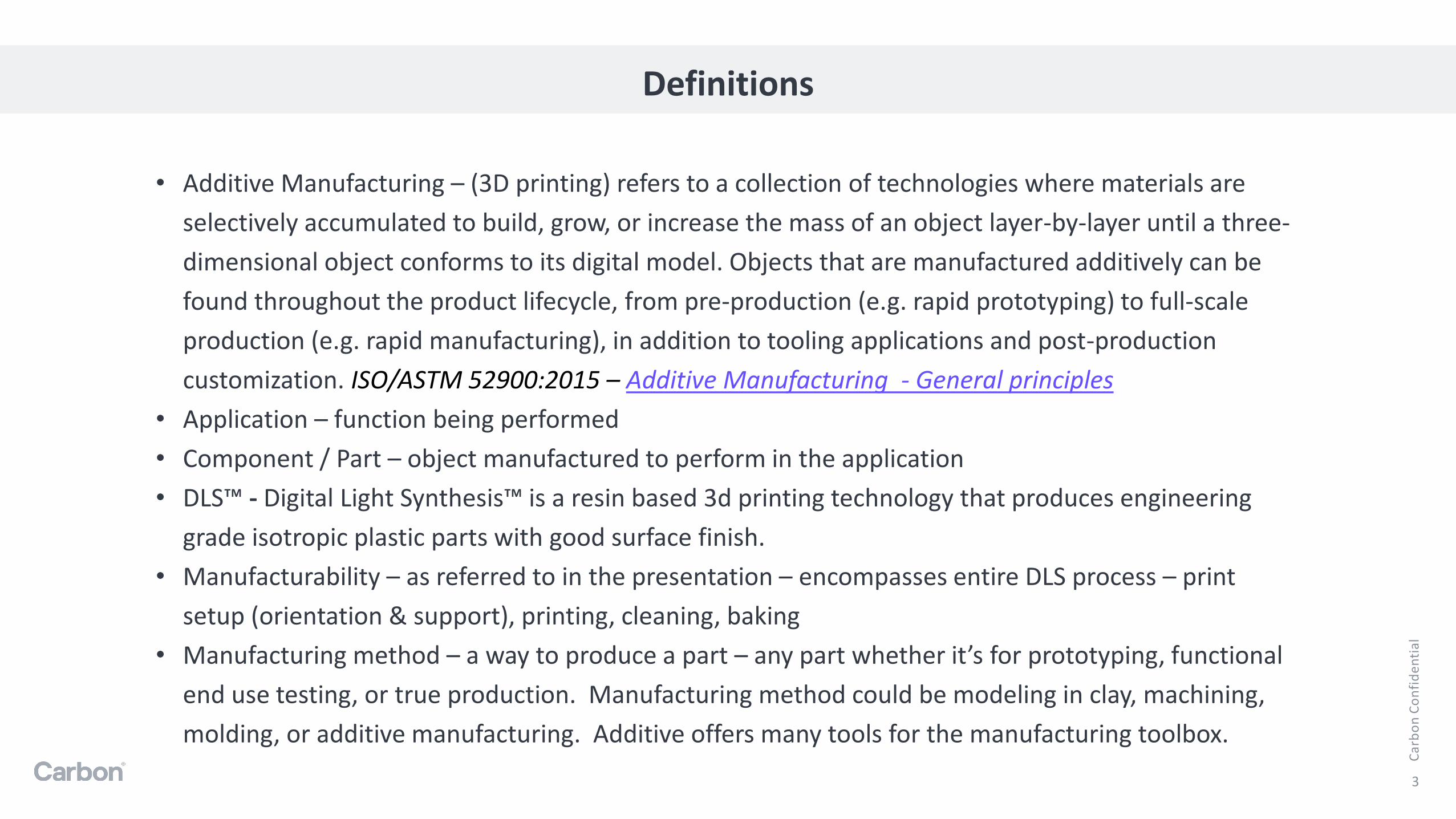
Definitions
3
• Additive Manufacturing – (3D printing) refers to a collection of technologies where materials are
selectively accumulated to build, grow, or increase the mass of an object layer-by-layer until a three-
dimensional object conforms to its digital model. Objects that are manufactured additively can be
found throughout the product lifecycle, from pre-production (e.g. rapid prototyping) to full-scale
production (e.g. rapid manufacturing), in addition to tooling applications and post-production
customization. ISO/ASTM 52900:2015 – Additive Manufacturing - General principles
• Application – function being performed
• Component / Part – object manufactured to perform in the application
• DLS™ - Digital Light Synthesis™ is a resin based 3d printing technology that produces engineering
grade isotropic plastic parts with good surface finish.
• Manufacturability – as referred to in the presentation – encompasses entire DLS process – print
setup (orientation & support), printing, cleaning, baking
• Manufacturing method – a way to produce a part – any part whether it’s for prototyping, functional
end use testing, or true production. Manufacturing method could be modeling in clay, machining,
molding, or additive manufacturing. Additive offers many tools for the manufacturing toolbox.

Ca
rbo
n C
on
fid
en
tia
l
Important Handouts
4

Ca
rbo
n C
on
fid
en
tia
l
Agenda
1. Introduction to Additive Manufacturing (AM)
2. AM Strengths
3. Successful Applications
4. Application Selection Criteria
5. How to Apply the Criteria
6. Designing for AM
7. Summary
5

Ca
rbo
n C
on
fid
en
tia
l
Brief Introduction to Additive Manufacturing
6
01

Ca
rbo
n C
on
fid
en
tia
l
Additive Manufacturing Processes
7
Relationshipwith
Customer
To learn more about these processes:• 3D Hubs – The Complete Engineering Guide 3D Printing• ISO/ASTM 52900:2015 – Additive Manufacturing - General principles• SME – Additive Manufacturing Glossary
Category Types Material
Binder jetting Plastic, Sand, Metal, Ceramic
Directed energy deposition LENS Metal
Material extrusion FDM Plastic
Material jetting Polyjet Plastic
Vat Polymerization DLP, SLA Plastic
Powder bed fusionSLS Plastic
DMLS, SLM Metal
Sheet lamination LOM Plastic

Ca
rbo
n C
on
fid
en
tia
l
Process Benefits
8

Ca
rbo
n C
on
fid
en
tia
l
Additive Manufacturing Strengths
9
02

Ca
rbo
n C
on
fid
en
tia
l
Additive Manufacturing Strengths
10
Additive processes offer benefits over traditional manufacturing methods.
Manufacturing Solution
Additive vs Traditional Manufacturing
• Design Freedom• Lattices
• Textures
• Organic designs
• Easy to implement iterations and customizations• User/Patient Specific parts
• Application specific parts
• Easily produce iterations to address issues in the design
• Economic advantages - especially for low volume• Quick turn around times
• No minimum buys
• Part consolidation
Key Concept: Use the additive strengths to drive value to your project (prototypes, parts, manufacturing solutions).
Parts

Ca
rbo
n C
on
fid
en
tia
l
DLS™ Strengths
11
To be able to decide if DLS™ manufacturing is the right process for the application, it’s important to know process’s strengths.
Design freedom allowed product team to find the perfect shape for performance.
DLS™ vs Machining/Injection Molding• Ability to produce un-moldable geometries
• Part consolidation
• Easy to implement iterations and customizations
• Economic advantages – especially for low volume
DLS™ vs Additive Technologies• Engineering grade materials• Fine features• Cosmetic surfaces• Watertight & Airtight parts with no secondary operation
Key Advantage: Carbon® technology merges engineering grade material properties with all the advantages of additive manufacturing while utilizing the same manufacturing process and material from prototyping to production!

Ca
rbo
n C
on
fid
en
tia
l
What makes a successful additive manufacturing
application?
12
03

Ca
rbo
n C
on
fid
en
tia
l
Application Successes – Categorized by Value
13
Design Freedom Economic Advantages Part Consolidation
Personal Customization Low Volume
Iterations & Short Deadlines
3 to 1
BIOLASE
Rails o
f Sheffield
Un-moldable Geometries
Becton, Dickinson, and Company (BD)
6 to 1

Ca
rbo
n C
on
fid
en
tia
l
What’s the secret?
14
Recipe for success:
• Material that meets the needs of the application
• Business Case
• A team with:- A vision and inspiration
- Ability to design to the function of the component• Knowledge of the chosen application
• Knowledge of the chosen manufacturing method
- Implementation strategy
- Good relationships with customers
TEAM
Vision
Inspiration
Strategy
Design to function
Manufacturing Method
Relationshipwith
Customer

Ca
rbo
n C
on
fid
en
tia
l
Application Selection Method
15
04
Ca
rbo
n C
on
fid
en
tia
l
16
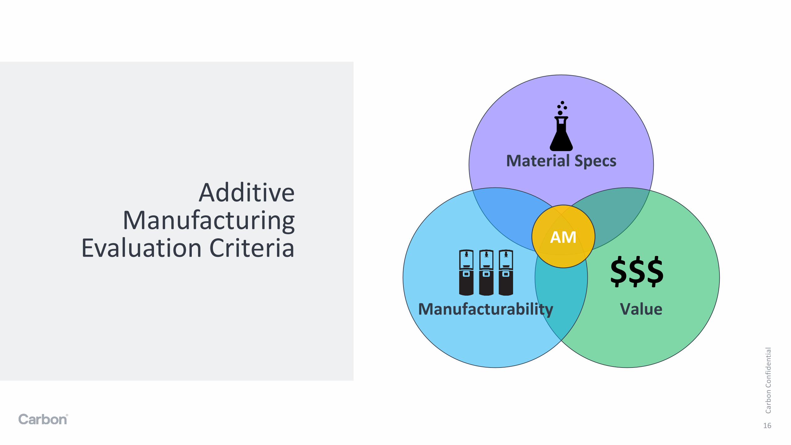
Additive Manufacturing
Evaluation Criteria
Material Specs
ValueManufacturability
AM
$$$

Ca
rbo
n C
on
fid
en
tia
l
Material Selection
17
Selecting a material:• Material type? Rigid or
Elastomeric
• Temperature requirements
• Chemical resistance
• Biocompatibility needs
• Mechanical performance
$$$

Ca
rbo
n C
on
fid
en
tia
l
Value
18
Exploring the value (business case) utilizing an additive process for your application:
What strengths can be utilized?
• What design freedoms become available?
• What performance improvements could be made?
• Could the manufacturing process of the component or assembly be streamlined?
What economic advantages can be utilized with AM manufacturing?
• Can you eliminate tooling cost?
• Can you eliminate minimum order buys (quantities and cost)?
• Do you have a short timeline? Need to iterate quickly?
$$$
Defining Advantages of DLS™ Manufacturing:• Engineering grade materials
combined with the advantages of additive
• Same material and process from beginning to end
Design Freedom Part Consolidation Economics
3 Categories of a Compelling Business Case:

Ca
rbo
n C
on
fid
en
tia
l
Manufacturability
19
DLS™ Manufacturability Specific Factors:• Quantity on build platform
• Post Processing- Support removal
- Cleaning
- Baking
$$$
Manufacturability encompasses the entire process of physically producing the part/component including printing and post processing (cleaning and bake).
The part design can greatly affect this category of the evaluation. Design principles for the process chosen can be applied to create a manufacturable part.
Does the part fit in the build envelop?
Can the part be optimized for the process?
Z
X Y
M2
X189 mm(7.4 in)
Y118 mm (4.6 in)
Z326 mm(12.8 in)
~50 mm
~80 mm
~25 mm
For Production Application:
• Ideally ~10 to 20 parts to build
LEGACY6-PART DESIGN
Tens of thousand deployed in stores across U.S
NEW SINGLE-PART DESIGN
DLS
™ E
xam
ple
Approximate part Size:

Ca
rbo
n C
on
fid
en
tia
l
Applying the Application Selection Method
20
05

Ca
rbo
n C
on
fid
en
tia
l
What you need:
21

Ca
rbo
n C
on
fid
en
tia
l
Identifying Good Fits for AM
22

Ca
rbo
n C
on
fid
en
tia
l
Part Consideration
23
Ca
rbo
n C
on
fid
en
tia
l
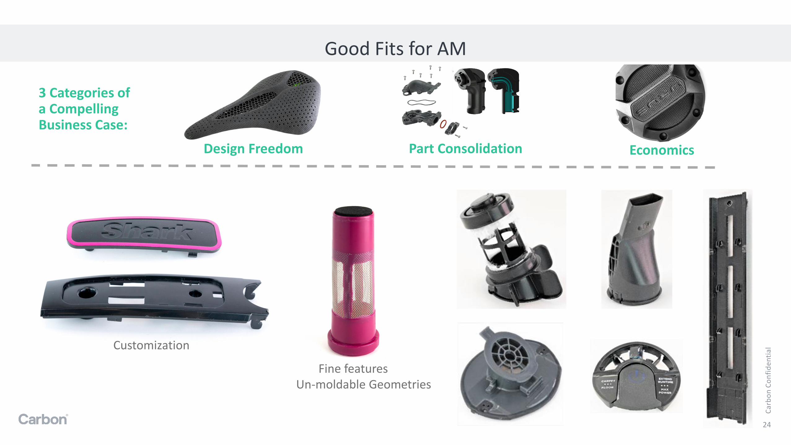
Good Fits for AM
24
Customization
Un-moldable GeometriesFine features
Design Freedom Part Consolidation Economics
3 Categories of a Compelling Business Case:

Ca
rbo
n C
on
fid
en
tia
l
Not a fit for AM
25
Locked designs
Parts easily made by other processes
High volumes
High dimensional accuracy
Simple geometries
Material requirements

Ca
rbo
n C
on
fid
en
tia
l
Designing for Additive Manufacturing
26
06

Ca
rbo
n C
on
fid
en
tia
l
Design Principles
27
Principles:
• Consistent wall thickness
• Gradual geometry changes
• No trapped volumes
• Self supporting
• CleanabilityARaymond Case Study
Ca
rbo
n C
on
fid
en
tia
l
Design Principles – Why apply
28
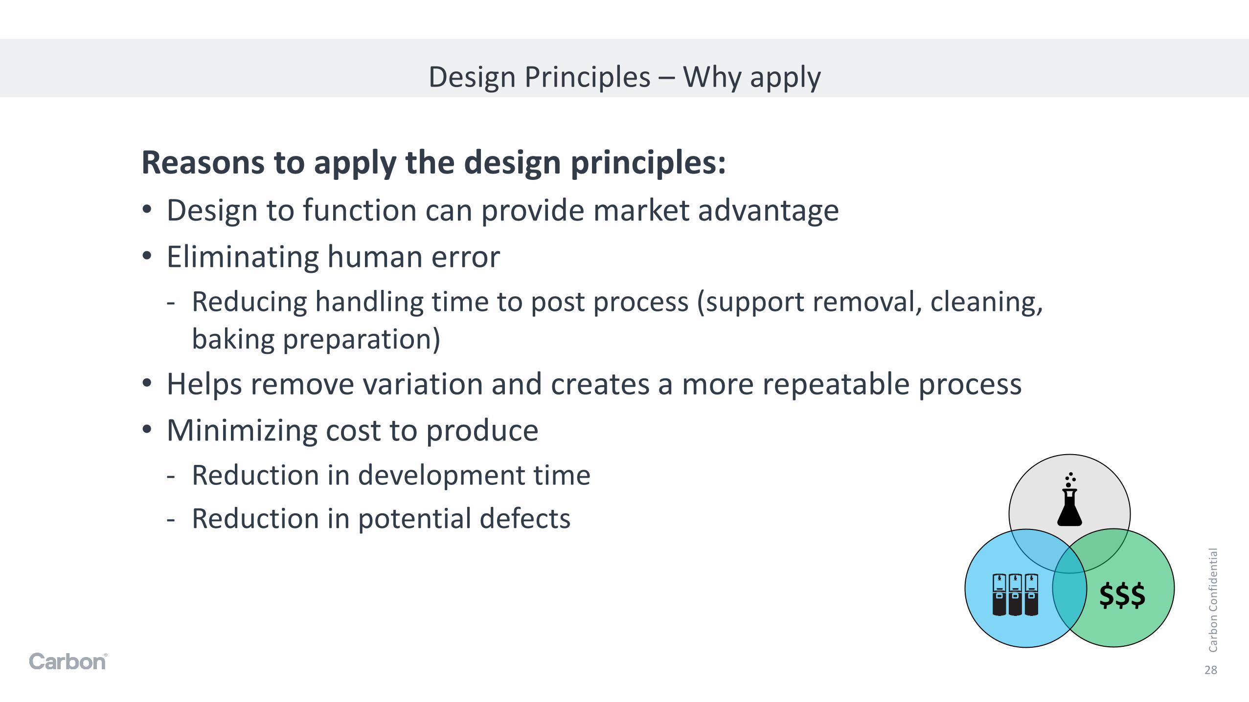
Reasons to apply the design principles:
• Design to function can provide market advantage
• Eliminating human error
- Reducing handling time to post process (support removal, cleaning, baking preparation)
• Helps remove variation and creates a more repeatable process
• Minimizing cost to produce
- Reduction in development time
- Reduction in potential defects
$$$

Ca
rbo
n C
on
fid
en
tia
l
Recommended Minimum Feature Sizes
29
Other:
• Radius – 0.5 mm (min, I prefer 1 mm)
• Fillets – Exterior corners - 0.5 mm + wall thickness
• Minimum thread size = M4

Ca
rbo
n C
on
fid
en
tia
l
Consistent Wall Thickness
30
Consistent Wall Thickness Reduces:
• Warping
• Shrink lines
• Large changes in print forces
- Heat
- Suction
- Resin flow
Concept
Design Recommendations:
• The same wall thickness throughout the part is not always possible, in this case make the thickness change very gradual. Curves and organic changes from thick to thin.
• For walls at minimum thickness, keep the height as short as possible.

Ca
rbo
n C
on
fid
en
tia
l
Gradual Geometry Changes
31
Gradual Geometry Changes reduces:
• Warping
• Resin flow bands
• Shrink lines
• Internal stresses that can cause failure points (example: cracking in bake
• Sagging during bake
• Large changes in print forces during print
Concept
Applications
Gradual geometry changes rule of thumb:
• No sharp edges or corners
- Use radius, fillets, chamfers
• Remember the parts are growing from a liquid resin, therefore the parts can be more organic. Use curves and natural changes from thick to thin to make geometry changes instead of steps, corners.
• Apply gradual geometry changes in all directions of the part, not just the printing direction.
Ca
rbo
n C
on
fid
en
tia
l
Gradual Geometry Changes
32
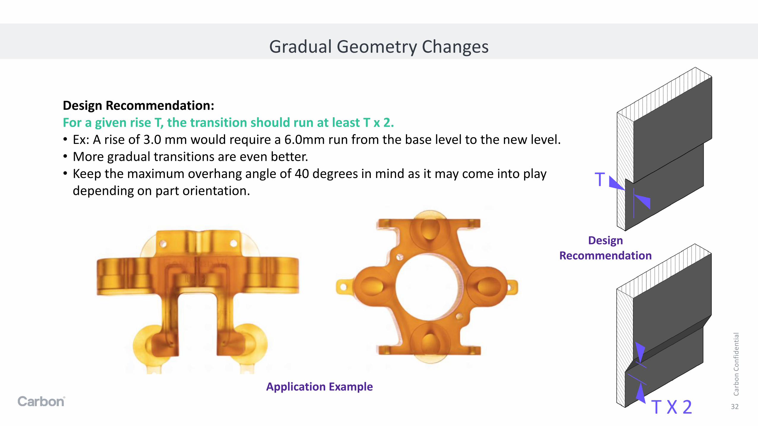
Design Recommendation:For a given rise T, the transition should run at least T x 2.• Ex: A rise of 3.0 mm would require a 6.0mm run from the base level to the new level.• More gradual transitions are even better.• Keep the maximum overhang angle of 40 degrees in mind as it may come into play
depending on part orientation.T
T X 2Application Example
Design Recommendation

Ca
rbo
n C
on
fid
en
tia
l
Self Supporting
33
Self supporting parts eliminates/reduces:
• Material usage
• Shift lines
• Handling time after print
• Cleaning
BD – Case Study on how this part was designed
Design Recommendations:
• Use fillets, chamfers to help transition the edges
• Support bosses and other overhang geometries with gussets
• Self supporting can also mean filling in space fillers and brining parts to meet the platform
Requires manual supportsHarder to clean
Original DLS Design

Ca
rbo
n C
on
fid
en
tia
l
No trapped volumes
34
Venting all volumes will:
• Eliminates suction forces during printing
• High suction forces can cause:
- parts to fall off the platform
- print defects such as holes delamination
- warping during bake due to internal stresses
• Improve cleanability of parts
Section through
example part
LOW PRESSURE
HIGH PRESSURE
Design recommendation:
• Vent volumes with minimum 2 to 3 mm vent holes
• May require more than 1 vent hole
• Vent blind holes for improved cleanability
Unvented Volume Examples

Ca
rbo
n C
on
fid
en
tia
l
Cleanability
35
Parts that are easy to clean eliminate/reduce:
• Handling time after print
• Human error
• Scrap
• Part inconsistency
• Part overexposure to solvent
Design recommendation:
• Vent all trapped volumes
• Vent blind holes
• Use gradual geometry changes
• No sharp edges – especially internal corners
• Feature spacing – use the bridge and overhand distance as a good starting point
• Self supporting where possible
Salt baked into a part
Resin trapped on part
Application Example

Ca
rbo
n C
on
fid
en
tia
l
Example Part - Housing
36
These parts were designed for DLS™ technology.
Can you pick out the features?
Prin
t Directio
n
Prin
t Directio
n
Platform Platform
Prin
t Directio
n

Ca
rbo
n C
on
fid
en
tia
l
Summary
37
05

Ca
rbo
n C
on
fid
en
tia
l
Design Summary
38
Design Principles:
• Consistent wall thickness
• Gradual geometry changes
• No trapped volumes
• Self supporting
• Cleanability
Design tips to support the principles:
• No sharp edges/corners
• Bring the part to meet the build platform
• Use organic/natural designs
DLS™ specific tips:
• Tie thin/delicate features into your part for stability in bake
• Feature spacing use the maximum overhang or bridge distance
• Threaded holes and metal inserts are usable with Carbon®
When possible design to the function of the application. Try to utilize the design freedoms that additive offers.

Ca
rbo
n C
on
fid
en
tia
l
Application Selection Method – Important Concepts
39
Strengths:Additive vs Traditional Methods• Ability to produce un-moldable geometries
and textures
• Part consolidation
• Easy to implement iterations and customizations (User and Patient Specific)
• Economic advantages – especially for low volume
DLS™ vs Additive Technologies• Engineering grade materials• Fine features – Logos, Threads• Cosmetic surfaces• Watertight & Airtight parts with no
secondary operation
Material Specs
ValueManufacturability
AM
$$$

Ca
rbo
n C
on
fid
en
tia
l
Carbon Website – www.carbon3d.com
• Handouts
• Engineering Handbook
• DLS ™ Design Quick Guide
• Materials
• Technical datasheets available under each material family
• Inspiration
• Meet the Additive MVPs
• Want to learn more?
• Webinars
• Ask an Additive Expert
• Case Studies
40
Carbon®Resources

Ca
rbo
n C
on
fid
en
tia
l
Online Basics:
Free
• 3D Hubs – The Complete Engineering Guide 3D Printing
• ASME Resources - Resources
• ISO/ASTM 52900:2015 – Additive Manufacturing -General principles
• SME – Additive Manufacturing Glossary
Paid course
• MIT – Additive Manufacturing for Innovative Design and Production
• UL – Additive Manufacturing Training and Education
Certifications:
• SME – Additive Manufacturing Certifications
• Barnes Global Advisors – Additive Manufacturing Certificates for Engineers and Business Professionals
41
Other places for training

Thank you