Embed Size (px)
Citation preview
a#L.)cm
a
NATIONALADVISORYCOMMITTEEFORAERONAUTICS
TECHNICALNOTE2919
THE ASYMMETRICADJUSTABLESUPERSONICNOZZLE
FOR WIND-TUNNELAPPLICATION
By H. JulianAllen
Ames Aeronautical LaboratoryMoffett Field, Ca.lif.
WashingtonMarch 1953 ‘
-AFMDC‘:‘~’L!B!Wlf“. -. .4A
?
P
TECHLIBRARYKAFB,NM ~
NATIONALADVISORYCOMKHT’EEFORAERONAUTICS IlllllllllllllllllllllluiCIClbLOllb ~
!CECENICALNOTE2919
TEEMYMMEHUC ADJUSTABLESUPERSONIC
FORWIND-TUNNELAPPLICATION
ByH.JulianAllen
SUMMARY
NOZZLE
Thedevelopmentofanasymmetrictypeofadjustablesupersonicnozzlesuitableforapplicationtowindtunnelsisdescribed.Thisnewtypeofnozzlepermitscontinuousadjustmentofthetest-sectionMachnumberwithouttherequirementof flexiblewalls.Uniformityofflowwithinthetestsectionaswellasthecompressionratiorequiredfortheattainmentofthesupersonicflowareconsidered.
. Theadvantagesanddisadvantagesofthisnozzlerelativeto theconventionalinterchangeable-fixed-blockandflexible-wallnozzlesarediscussed.
.
INTRODUCTION
Inthedesignvelocitystreaminvelocitygradients
ofanywindtunnel,theattainmentofa uniformthetestsectionistheprimeconsideration.Theparallelandnormaltothetest-sectioncenterline
must be smallinorderthattheresultsofaircraftmodeltestsmaybeappliedwithconfidencetothedeterminationofthefree-flightaircraftbehavior.To determinetheeffectsof compressibilityontheaerodynamiccharacteristicsofaircraftmodelsintheconventionaltypeofwindtun-nel,thetest-sectionairspeedmust,inaddition,be adjustable.
In thefamiliarsubsonicwindtunnel,neitheroftheserequirementsisdifficultto obtain.An entrancenozzle,thewallsofwhichprovidea smoothandcontinuouspassagefromtheairentrancethroughtheflat-walledtestsection,willsufficetopreventimportantgradientsnormalto.thetunnelaxis. Ina nonviscousfluid,zeroaxialvelocitygradientsatthetestsectionwouldobtainwithparallelaudflatwallsat thetestsection,butfora realfluidsomeflareofthewallsmustbe providedto
b allowforthegrowthoftheboundarylayeralongthenozzlesurfaces.Withsucha tunnel,thetest-sectionairspeedmaybe veryconvenientlyadjustedby changingtherotationalspeedofthedrivingfanorcompressor.
4
2NACATN 2X9
Withthesupersonicmentsisnotsosimple.wallshapeswillpromote
windtunnel,theattainmentoftheserequire- d
Onlya certainfsmilyof smoothcontinuoustherequireduniformityofflow,while,even k“
moreimportant,thevelocityatthetestse&tioncanno longerbe variedby changingtherotationalspeedofthedrivecompressors.Thislatteranomalymaybe convenientlyshowninthefollowingmanner:
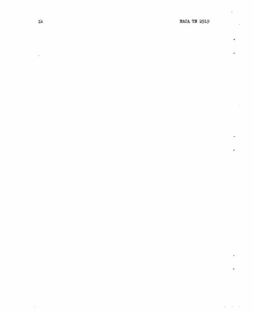
.-Consider
theflowinthe”nozzleoffigure1 wherein.theexitpressurePI maybeloweredwithrespecttotheentrancepressurePo. Sincethemassflowmustbe thesameatianypositionalongthenozzlethen,if-itisassumedthatflowconditionsareconst?nrKacrossaziygivencross-section,
pVA= constant.—
where,atanypoint,
P density
v velocity
A cross-sectionalareanormaltotheflowdirection
Thatis,”.-.
d(pVA)= O
orthelogarithmicderivative
(1)
.- ‘-—
●
_— -——
Bernoullit&equationfor-compressibleflowisgivenby
dp _P - Viv
wherep isthelocalpressure.
Sincethesquareofthevelocityof soundisgivenby—..
dp a2.---=dp
.—
.-
then
dp VdV—. .—P a2 =-M2:
NACATN 2919
andequation(1)becomes
dll dV &,v (1—=-—A
(2)
If thevelocityat allstationsislessthansonic,thenfromequation(2),thefsmiliarresultthatthevelocityincreasesas theareadecreasesisobtained.At supersonicspeeds,when 1-M2 isseentobe negative,thereverseistrue.At thespeedof sound,moreover>1-M2 is zerosothat dA mustbe zero.Thatis,ifa Machnumberofunityisattained,itisonlyattainedat theminimumarea,orthroat,section.
Theflowbehavioras theexitpressurePI isreducedbelow P.isthenthefollowing:Startingfromrest,thevelocitywillincreaseandtillbe a maximumatthethroat.Thisisthefsmiliarconditionwitha subsonicwindtunnel,as shownby curveA offigure1. When PIissufficientlybelowP. tohavethesonicspeedattainedat thethroat(designateda*)as shownby curvesB andC,no furtherreductionin P1 willincreasethethroatvelocityandthenozzleis saidtobe
. “choked.”Instead,a supersonicflowdownstreamof thethroatwillbeobtainedwhichwillbe abruptlyterminatedby one‘ormorecompressionshockwavesnormalto thestream,theaxialpositionofwhichwillbe
. determinedlythepressuredifferenceP. –Pl whichisprovided.Thiscaseis shownby curveC.
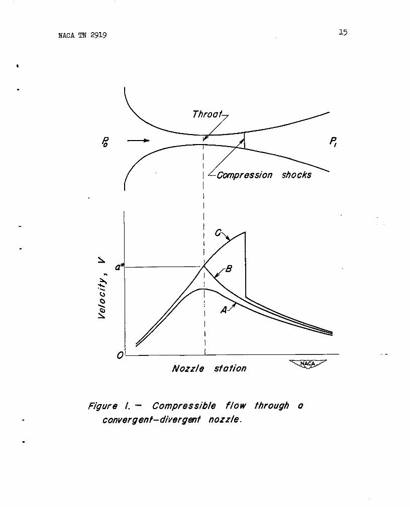
Sincetheflowis chokedthenit is clearthataheadof thenormalshockwavethevelocityatanystationisa functiononlyof thelocalareaas itisrelatedtothethroatarea. Thusfora supersonicwindtunnelthespeedat thetestsectionisuniquelydeterminedby theratioofthetest-sectionareatotheminimumor throatareaaheadof it,thepressuredifferenceP.– I?lbeingthatrequiredtomaintainthenormalshockdownstreamofthetestsection.Theratioofareasrequiredasafunctionoftest-sectionMachnumberisshownfora nonviscousfluid(whereintheboundarylayerneednotbe considered)in figure2.,
I1 Thenozzleof figure1 couldprovideanysupersonicspeedrequired
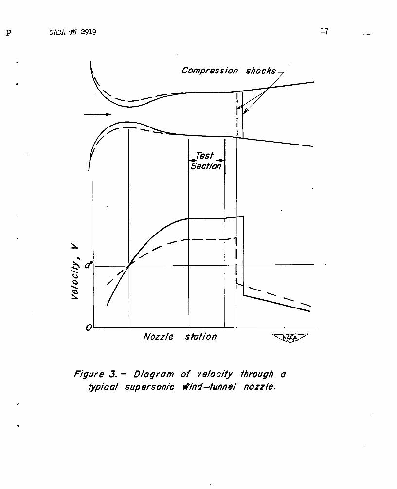
fora modeltestifthemodelweremovedto theappropriatepositiondownstreamofthethroat.Theflow,however,wouldbe unsatisfactorybecauseoftheaxialvelocitygradient.Instead,a passagewithaconcave-walledsectionfollowinga convex-walledsection,suchas showninfigure3, wouldberequired.
To obtaintherequiredspeedat thetestsection,thegeometry.ofthenozzleforwardofthetestsectionmustbe varied(asindicatedby. thedottedcurves)soas to obtaintheproperratiooftest-sectionareatothroatarea,aswellas toprovidesucha passageaswillmeetthe
* requiredzerovelocitygradientsatthemodelposition.Thislatterrequirement,notso simpletoattainas inthesubsoniccase,hasbeen
4 NACATN 2919
classicallytreatedbyPrandtlandJ3tisemanh-employingthemethodofcharacteristics.Applicationofthemethodhasbeenthoroughlytreatedinnumerouspapers.(See,e.g.,refs.lsiiii2.)
Clearly,itiwouldbe possibletodesi&na seriesof interchangeablenozzleshapesoffixedformwhichwouldgiveasmahydifferenttestMachnumbersasdesire-d.Thishadbeentneschemeemployedformanysuper-sonicwindtunnelsbuilttodate. Ithastheadvtitageofisimplicity”butsuffersfromtwomajordisadvantages:First,onlyasmanysupersonictestspeedsareavailableas individtzalfixednozzlessothatifmallspeedincrements,aredesiredthenumberof-nozzlesrequiredbecomeslargeandthecostof suchan installationaccordinglygreat;and,second,forlargewindtunnelstheschemebecomesImpracticalmechanically,sincethenozzleblockweightbecomessogreatas tomakethechangingoftheblockstoodifficultandtimeconsuming.
To avoidthedifficultiesofthefixednozzles,thevariablegeometrynozzlewasdeveloped,With*hisarrangement,as ithasbeenemployedtodate,twoapposite.wallsofthenozzhare rigid,flat,andparallel,whiletheremainingtwowallsaresufficientlythinandflex-ibletobe warped,by a systemof jacks,to-therequirednozzleshapes.Thismethodhastheadvantagesthatanytest-sectionspeedovertheextremitiesof thespeedrsmgemaybe obtainedbyproper.positioningof thejacks,andthechangemaybemadewithoutdismantlingthetumlelas isrequiredwiththeinterchangeablenozzlesyKtem.Of cotise,therearenumerous-disadvantagestothemultijack,f“lexible-wallnozzle.Theflex-iblewallmusthe sufficientlythinasnottooverstresstheplateswhenthewallsareflexedtoencompasstherequiredspeedrange.On theotherhand,tokeepthejackspacingaslargeas~ossibleandsotoreducethenumberof jacksrequired,theplatemustbe maintainedasthickaspos-sibletopreventsaggingorhoggingoftlie>latebetweenjacksduetolocalair-pressuredifferencesacrosstheplateaswellas,ina minordegree,totheweightoftheplateitself.Thushighplatestressesareoccasioned,andhenceoneobjectiontothistypeofnozzleisthatdangerofoverstressing.of theplate(withresultingpermanentsetor structuralfailure)caneasilyoccurby improperjackbperation,necessitatingelaboratesafetydevicestopreventsuchan occurrence.
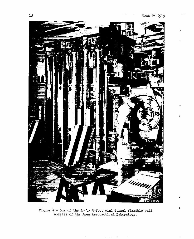
Thedesignandconstructionofthejackattachmen@to suchahighlystressedplate,theelaboratesysteni-ofjacks,eachofwhichmusthavetheabsoluteminimumofbacklash,theccxnplicationofrequiringpressuresealswhichwillnotrleakandyet%f.11allowmotionoftheplate,thecomplexcontrolsystemforthejacks,andmanyotherfactorsintroducemechanicalcomplexity.TheflexiblenozzleoftheAmesl-by s-footsupersonicwindtunnelshowninfigure4 atteststothisfact.As a resultof thiscomplexity,highcostconstitutesa majorobjectiontotheflexible-wallnozzle.
.
—
—.
.
.-
NACATN2919 ‘5
As is evidentnom theforegoing,neitherthefixed-interchangeablenozzlesystemnortheflexible-wallnozzlemethod,as ithasbeenused,constitutesa solutiontotheproblemof obtaininga suitablesupersonicnozzleforwind-tunnelapplicationsatisfactoryinallrespects.
At theAmesAeronauticalLaboratory,severaluniquemethodsforsolvingthisproblemhavebeendeveloped.It isthepurposeofthispayertodescribeonenewtypeofnozzlethathasbeendevelopedbytheNACAwhich,obviatesmostofthedifficultiesof theoldertypesthathavebeenpreviouslyemployed.
THEASYMMETRICADJUSTABLENOZZLE
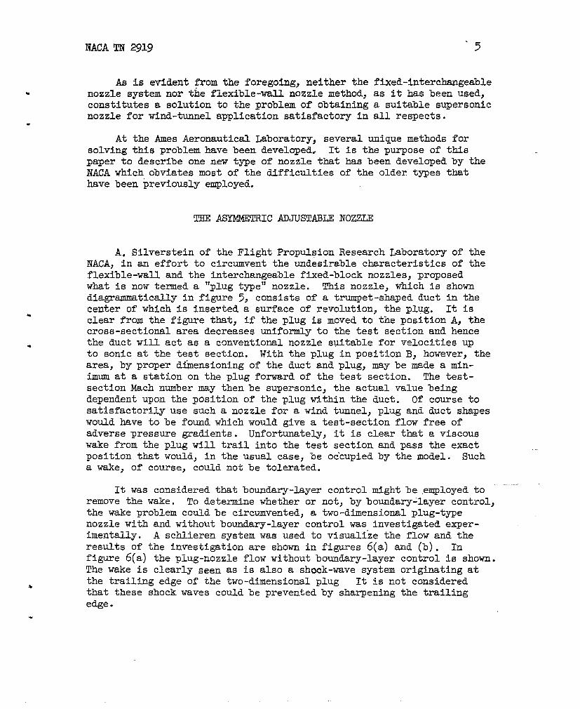
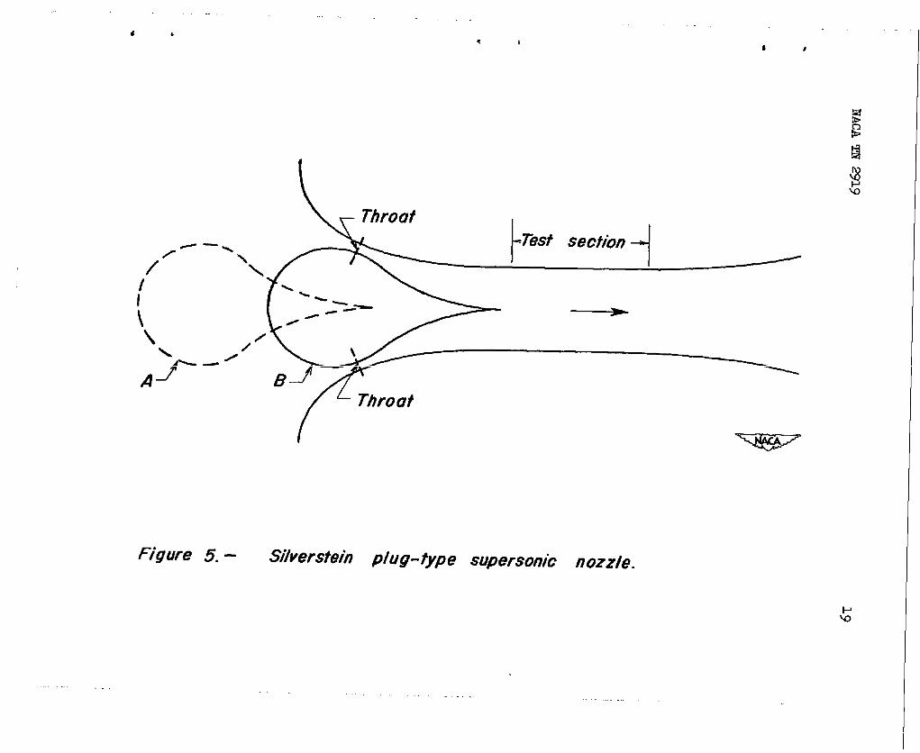
A. Silversteinof theFlightPropulsionResearchLaboratoryof theNACA,inan effortto circumventtheundesirablecharacteristicsof theflexible-wallandtheinterchangeablefixed-blocknozzles,proposedwhatisnowtermeda “plugtype”nozzle.Thisnozzle,whichisshowndiagrammaticallyinfigure5, consistsofa trumpet-shapedductinthecenterofwhichis inserteda surfaceofrevolution,theplug. It isclearfromthefigurethat,iftheplugismovedtothepositionA, thecross-sectionalareadecreasesuniformlytothetestsectionandhencetheductwillactas a conventionalnozzlesuitableforvelocitiesupto sonicat thetestsection.WiththepluginpositionB, however,thearea,by properd~ensioningof theductandplug,maybe madea min-imumata stationontheplugforwardof thetestsection.Thetest-sectionMachnumbermaythenbe supersonic,theactualvaluebeingdeyendentupontheTositionof theplugwithintheduct. Of coursetosatisfactorilyusesucha nozzlefora windtunnel,plugandductshapeswouldhavetobe foundwhichwouldgivea test-sectionflowfreeofadversepressuregradients.Unfortunately,it isclearthata viscouswakefromtheplugwilltrailintothetestsectionandpasstheexactpositionthatwould,intheusualcase,be oc’cupiedby themodel.Such
.
a wake,of course,couldnotbe tolerated.
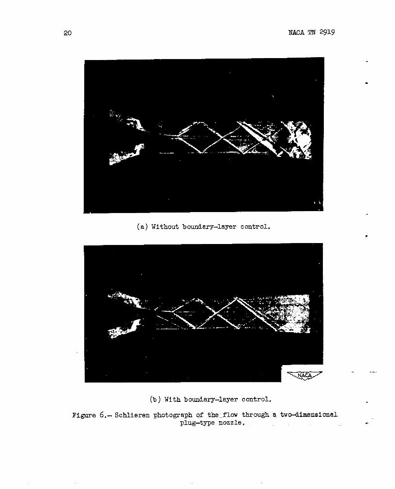
Itwasconsideredthatboundary-layercontrolmightbe,employedto -“--removethewake. To determinewhetherornot,byboundary-layercontrol,thewakeproblemcouldbecircumvented,a two-dimensionalplug-typenozzlewithandwithoutboundary-layercontrolwasinvestigatedexper-imentally.A schlierensystemwasusedtovisualizetheflowandtheresultsoftheinvestigationareshowninfigures6(a)and(b). Infigure6(a)theplug-nozzleflowwithoutboundary-layercontrolisshown.Thewakeisclearly~em as isalsoa shock-wavesystemoriginatingatthetrailingedgeof thetwo-dimensionalplug Itisnotconsideredthattheseshockwavescouldbe preventedbysharpeningthetrailingedge.
6 NACATN 2919
Theeffectupontheflowof introducinga boundary-layersuctionslotisseeninfigure6(b).It isevidentthat,althoughthewakewidthisreduced,it isnota significantuimprovement.Thetrailing-edgeshocks.alsopersist.Moreover,theboundary-layersuctionslotinreducingtheboundary-layerthicknesseffectivelyalterstheplugshapeinsucha wayastocreate–anaddit-iunalcompressionshockattheslot.IftheTlugsurfacewereof’poroysmaterial.soasto allowcontinuousboundary-layerremoval,theflowwouldprobablybe consider-ablyimproved.Neverthelessit isdoubtfu14hata completelysatis-factorynozzleforwind-tunnelapplicationcouldbe developedusingtheplugmethodforspeedcontrolbecauseoftheinherentdisadvantageofhavingtheplugtip directlyupstresmof.thetestposition.
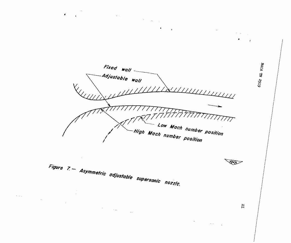
In anefforttorealizetheadvanta~es-cd’theplug-typenozzleand,atthesametime,avoidtheadversepli@wake,theauthorconceivedoftheasyuznetric-nozzleshowndiagrammaticallyinfigure7. L Thelowerwallo&the two-dimensionalarrangementishorizontallytranslatablewithrespecttotheupperwall.Withthelowerwsllmovedforwardtheminimumareaforwardofthetestsectionisdecreasedandthetest-sectionMachnumberaccordinglyincreased,andviceversa.Noproblemofa plugwakearisesforthistypeofnozzleand,presupposingthatwallshapescouldbe formedto giveuniformflowinthetestsectionoverthewholespeedrangeforwhichthenozzlewouldbe employed,sucha nozzlewouldbe satisfactory.Thereremainstheproblemastowhethertheasymmetrywouldpromoteundesirableverticalpressuregradientsofseriousmagnitude.
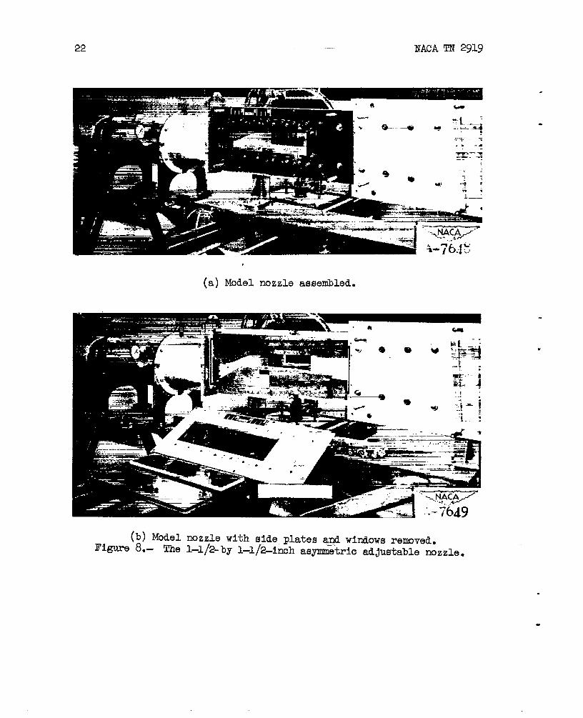
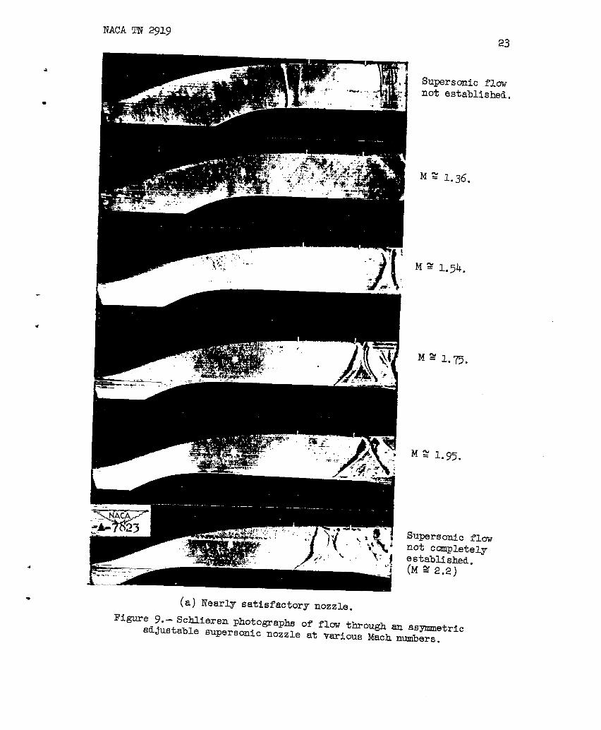
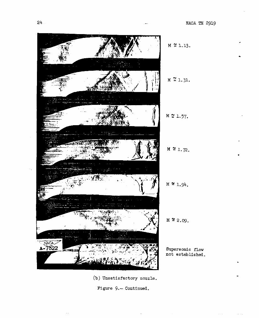
To~ermitstudiesof theflowthoughsucha nozzle,thetrislnozzleshowninfigure8 wasconstructed.Duringthecourse0$theexperiments,whichwereconductedbyMr.ZegmundBlevissoftheLaboratorystaff,numerousupperandlowercurvedblockswereinvestigated.Side-wallpressuremeasurementsweremadeandschlierenpicturesoftheflowweretakentodeterminetheadequacyofthenozzleconfigurations.
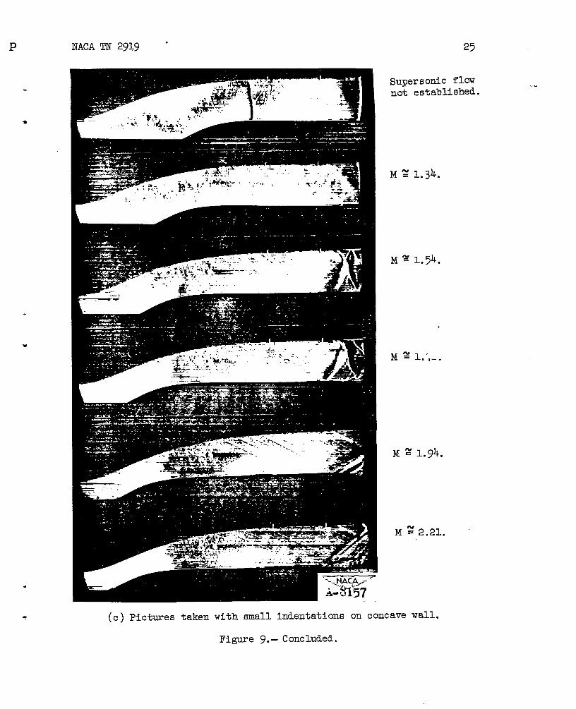
Intheearlystagesof thisinvestigate.cg,thenozzleshayeswerecrudelydeterminedby simplycaniberingsymne.tricalnozzlesthatPrevio~”experiencehadindicatedtobe satisfactory.Inlaternozzles,theflowwas anslyzedby themethodof characteristicstodeterminewhataltera-tionsofnozzlesh~eswouldimprovetheflows.Typicalschlierenflowphotographsof someofthenozzlesinvestigated”’sreshowninfig-uresg(a),(b),and(c). Thenozzleoffigureg(a)gavenearlysatis-factoryflow,whilethat--offigureg(b)(anozzlewhichwasshortenedtomaketheassemblymorecompact)isdefinitelyunsatisfactory,asisevidencedby theshockwaves.Forsatisfactoryflow,Machlinesinthetestsectionshouldbe straightandparallel.To demonstratetheadequacyofa nozzle,inmme casesfinescribelinesweredrawninthe
z,-—
.
—
lItisclearthatthisnozzleis,inessence,one-halfofa two-dimenslonalplug-typenozzle,
NACATN 2919 7
uppersurfaceperpendicularto theflowdirectiontopromotesuchweakshockwavesinthetestsectionasto approximateMachwaves.Theperformanceofa nozzlewithscribemarksisshowninfigure9(c).Theflow,aspredicted.by theMachlines,is seentobe satisfactory.
Somefurtheralterationsweremadeto thenozzlesto improvetheMachnumberrsmgeoverwhichsatisfactoryflowcouldbe obtained.Itwasparticularlydesirabletobe ableto operate,withsatisfactorysupersonicflow,as closetoMachnuniberunityaspossible.Aftersomefurtherrevisions,a minimumsupersonicMachnumber.scmewhatlessthan1.1wasattained.ThemaximumMachnumberforsatisfactoryflowwas2.0. Althoughsomewhathigherspeedscouldbe attained,separationoftheflowwasproneto occuronthelowerwallinthetestsection.
Theseparationofflowwhichoccursonthelowersurfaceisfelttoariseinthefollowingmanner:Tn thecsmberedsectionsofthenozzleupstreamofthetestsection,thepressureat anystationmustbe lowerattheconvexwallthanat theconcavewallinorderthattheflowmaybe turnedalongthecurvedpath. In themainbodyofthestresm,thefluid’isnotinfluencedimportantlyby theviscosityandforthisfluidthecentrifugalforceoneachelementfollowingthecurvedpathiSexactlybalancedby thepressuregradientacrossthenozzle.Theflowinthemainbodyofthestreamisthusnotinfluencedby thefactthatcaniberexists.Theairintheboundarylayermovesata lowervelocitysothatthecentrifugalforceon eachelementisinsufficienttobalancethepressuregradient.Hence,theairwithintheboundarylayeronthesidewallswillmovearoundthepassagewallstowardtheconvexsurface.Theintegratedinfluenceofthecurvature
‘ isthereforeto collecta muchthickerboundarylayerat thedownstreamstationsontheconvexplatethsmontheconcavesurface.ThiS thickerlayeris,of course,moreproneto separationundertheadversepres-suresoccurringinthediffuser.
Itwasapparentfrompressuresurveysalongthewallsofthenozzlethatverticalpressuregradientsoccurredinthetestsectionatthehigherspeeds.Howeverjtheindicationswerethattheseadversegradientswouldnotbe tooseriousup to a Machnumbercloseto2.0.
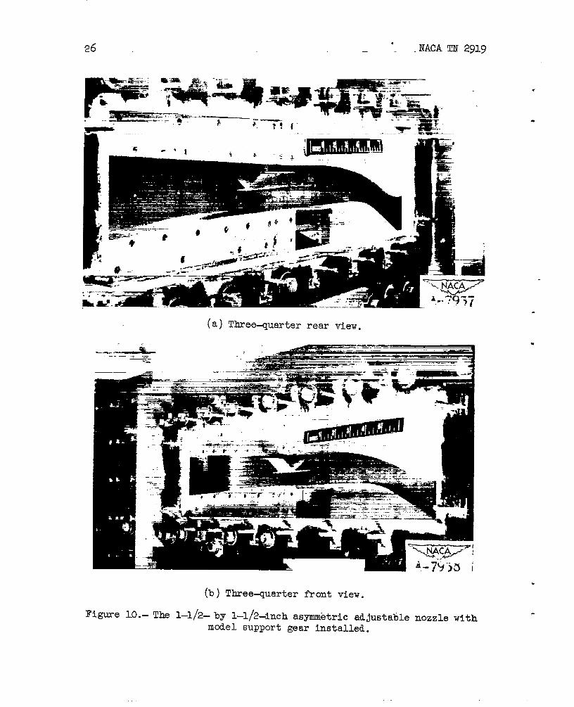
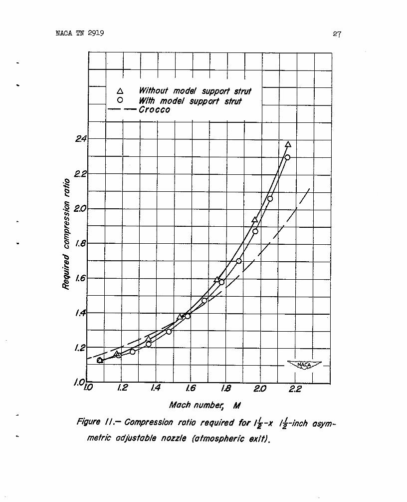
Theinvestigationofthenozzlewasextendedto determinethecompressionratiorequiredtomaintainsupersonicflowthroughthetestsection.To simulate.as closelyaspossiblea nozzlesuitableforwind-tunnelapplication,thenozzlewasconstructedtopermitthepresenceofa modelsupportgear,showninfigure10,immediatelydownstreamof thetestsection.In orderthatatMachnwbersclose
8 NACATN2919
tounitysucha supporl-gearwouldnotchoketheflowatthepositionofthesupport,thesideandtopwallswereflaredtokeepthecross-sectional.areaatthepositionofthesupport-geargreaterthanthatatthetestsection.This,ofcouxse,incurreda ratherrapiddiver-genceoftheflmedwallsinthissectionof-thediffuser.Thedif-fuserfollowingthesupportgearwasofthefamiliarsubsonictypewitha 3° halfangleofidiffusionat eachwallas a maximum.
b
Thecompressionratiosrequiredtomaintainsupersonicflowweredeterminedwithmd without-thesimulatedmodel-supportgearinstalledandareshowninfigure11. Thepresenceofthesupportgear@rovestheperformanceaswouldbe expectedbecauseOftheflaredwallsoppositethepositiontakenby thesupportgear.TheimprovementduetothepresenceofthesupportgearisprobaQlyalsodue,in-part~tothesupersonicdiffusioncausedby theobliqueshocksystempromotedby thestrutsupport.
Thefactthattherequiredcompressionratiosatthehigher~ch _.numbersisgreaterfortheasymmetricnozzlethanfor.thesymmetricnozzlesconsideredby Crocco(ref.3) isprobablypartlyattributabletotheadverseeffectoftheunusuallythickboundarylayerontheconvexwallofthediffuser.Anotherfactorwhichprobablycontributestothischaracteristicistheflaredsectiontopermitlowsupersonicspeedoperationwiththesupportstrutinplace.Testsofa symmetricnozzlewithsimilarcompensation-forthesupp~rtstruthasalsoshownloweredefficiencyathighMachnumbers.
i.-
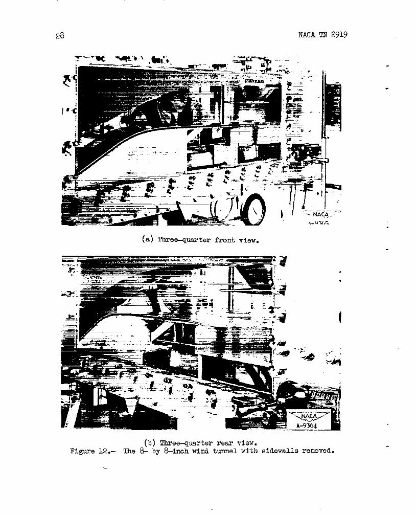
Theresultsobtained-fromthetestsofthe1-1/>by l-l/2-inch–modelnozzledemonstratedthatoneofthistypewouldperformsuffi-cientlysatisfactorilyforapplicationtoa largewindtunnel,anditwasdecidedtoemploysucha nozzleintheAmes& by &foot supersonicwindtunnelwhichwastobe constructed.
.-Itwasdeemedadvisable,
however,to furtherinvestigatethenozzleas“amodeloftheproposedoneforthe& by &footwindtunnelusingthelargestsupplyofdry
—
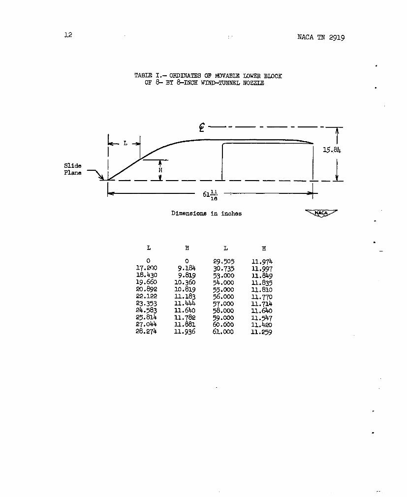
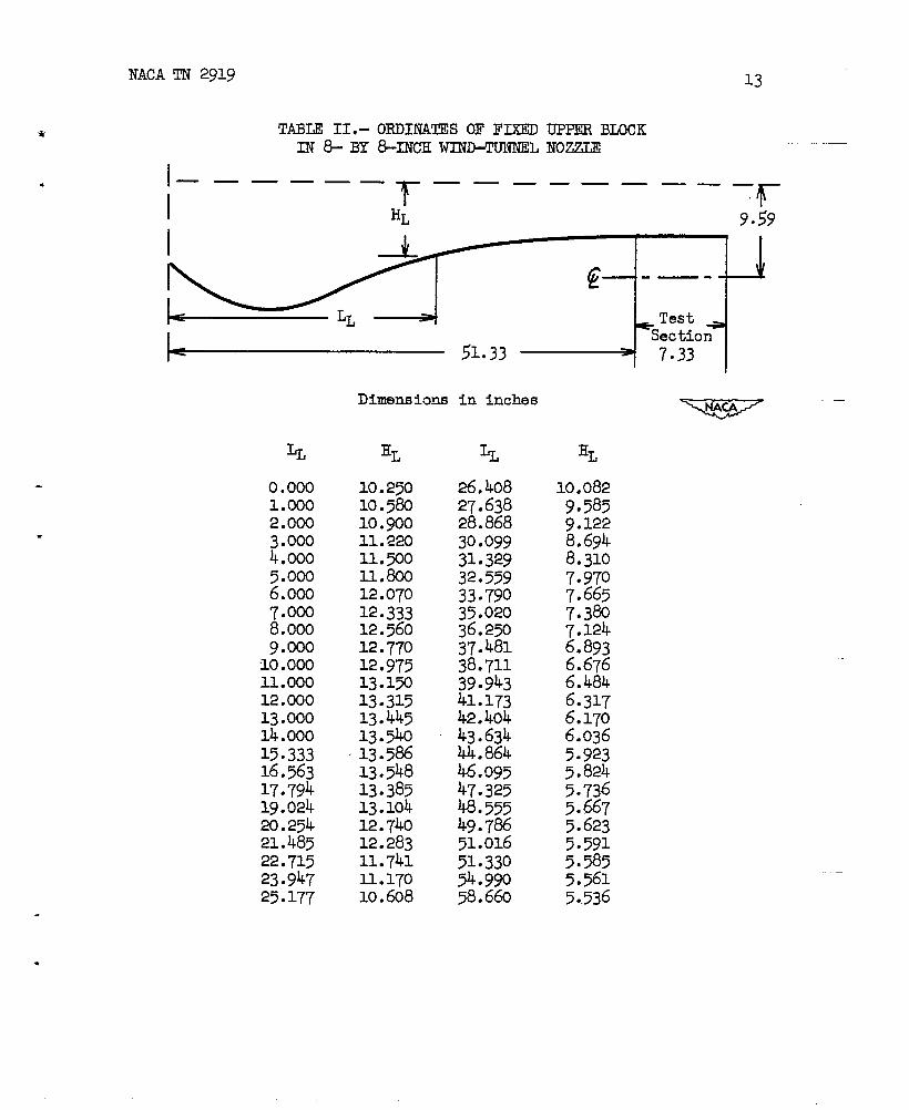
airathighpressuresavailableatthelabor~tory.Accordingly,am&by 8-inch”windtunnelemployingtheasymmetricadjustablenozzlewasconstructed.Thiswindtunnelisshowninfigure12withthesideplatesremovedto showthenozzleshape.Ordinatesfortheloweranduppernozzleblocksaregivenin_tablesI and_II,respectively.p
——. . .———
.2Asregard=thecontinuityofthecurvesbetween0rtiIIahf3) fairnesshasbeendeterminedatAmesAeronauticalLaboratoryusinga simplecurvaturegageconsistingoftwofixedposts_witha thirdmovablepostlocatedmidwaybetweenthe,others.Themovablepostisdirectlyconnectedtoa dialgageto readthedeflectionofthemovable
.—s
relativetothefixedposts.Forthegages..that~ve beenusedin “-the1–by >footand6-by &foot tunnels@ thelaboratory,thefixedpostshavebeenseparatedone-thirty-sixthofthetest-section w
height.Forsucha gage,experiencehasindicatedthattheper-missibledeviationof thecurvaturefromthelocalmeanasmeasured
NACATN 2919 9
Whereaswiththe1-1/2-by l–1/2=inch-modelnozzlethemovableblockwaschangedinpositionmanuallyandbolteddownforeachset-ting,themovingelementof the&by &inch nozzlewasactuatedbyaleadscrewfrom~tsidethenozzle.Leakagethroughthegapbetweenthemovingblockandthesidewallsofthe& by 8-inchtunnelwaspreventedby an inflatablebunarubberseallocatedintheedgesofthemovingelementwhichboreagainstthefixedwalls.
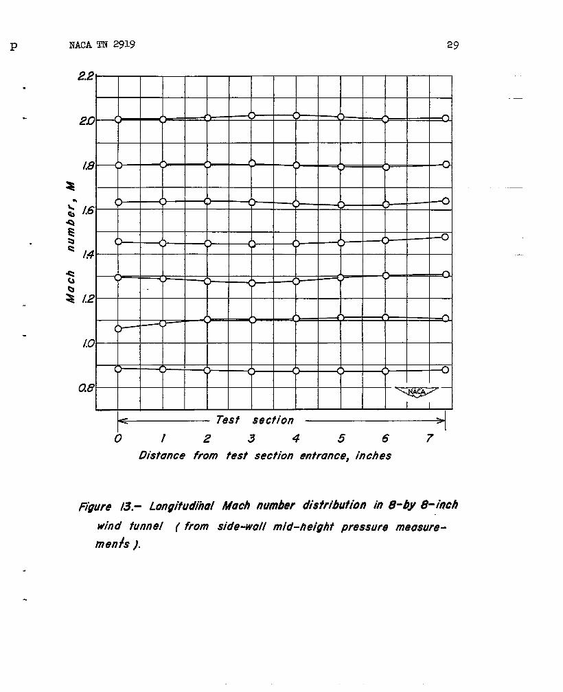
Staticpressuresurveysweremadeusingorificeslocatedinthewallsofthetunnel.TypicaldistributionsofMachnumberfromthebeginningto endofthetestsectionatbothsubsonicandsupersonicspeedsareshownin figure13. It is seenthatoverthefulltest-sectionlength,whichisnearlyequalto thetest-sectiondepth,deviationofMachnumberalongtheaxisis inonecase(M%1.1) aslargeas*2 percent.Fora modelsmallenoughtobe investigatedwithoutwallinterferenceatMachnumbersneartheminimtiof 1.1,themodellengthwillbe oftheorderofhalfthetest-sectionheightforwhichtheMachnumbervariationalongthemodelcanbe kepttoabout*0.~percent.
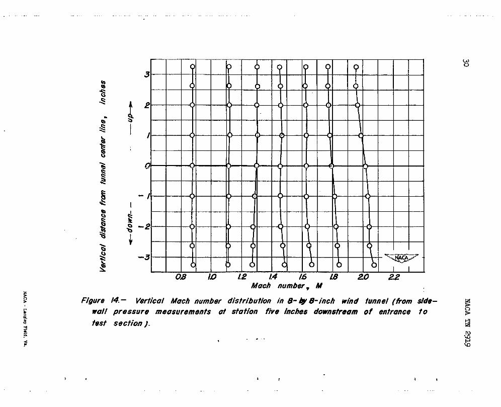
Surveyswerealsomadeto determinetheverticalgradientsinthetestsectionfromsubsonicto supersonicspeeds.Resultsofa typicalsurveyareshownin figure14 (forthessmeblockpositionsas infig.13)fortheverticaldistributionofMachnumberat a stationnearthecenterofthetestsection.Theverticalgradientsaregen-erallysatisfactoryalthougha gradientispresentatMachnumbersnear1.2and,asnotedpreviouslyforthe1—1/>by l-1/2-inchnozzle,atMachnumbersnear2.0.
CONCLUDINGREMARKS
Theasymmetricadjustablenozzlepossessesseveralmarkedadvan-tagesovertheinterchangeablefixed-blocknozzleandtheflexible-wallnozzle.
Comparedwiththefixed-blocknozzleit IsclearthatthemajoradvantageoftheasymmetricnozzleisthatanyMachnumber(through-outtheattainableMachnumberrange)canbe obtainedby translationofthemovableblock;whereaswiththefixedplates,onlyasmsmyMachnumbersastherearefixednozzlesareavailable.Againjforthe
2(Continued)by thedeflectionofthemovinglegwithreferencetothefixedlegsis0.00@ ofthedistancebetweenthefixedlegs.Forthe&by &inchwindtunnel,thecurvaturevariationwasinvestigatedusinga gagewithfixedposts1 inchapart.Thesurveyshowedthisnozzlesomewhatbelowstandsrdinthat,inat leastoneinstance>a deviationfromthemeanof0.0008inchwasmeasured.
---
—
10 NACATN 2919
fixed-blocknozzleprovidedwithblocksto givemorethantwoorthreeoperatingMachnumbers,thehighcostofthemachinedblockswillmorethanoffsetthecostofthemovableblockdriveendthesealinggearintheasymmetrictype.Finally,forlargewindtunnels,theinter-changingofblocksrequiresunwieldyandexpensiveblock-changinggearaswellasanunnecessarilylongtimetomaketherequiredchanges.
Comparedwiththeflexible-wallnozzleit isevidentthatbecauseofitherelativemechanicalsimplicityoftheasymmetricnozzlethecostof sucha nozzlewillbe considerablylower.A secondadvantageisthatthewallsarerigidandhencemaintaintheiruniformityofcurvatureincontrasttotheflexibleplateswhereinscallopingcanoccurbetweenjack-supportpoints.A third-advantageoftheasymmetrictypeisthatthereislittlepossibilityof structural-@nageto thenozzle.As notedpreviously,structuraldamagecameasilyoccurinflexiblenozzlesdueto improperoperation.ofthejacksalthoughbyproperdesignthisdangercanbe alleviatedtoa largeextent.Finally,withmostoftheflexible-wallnozzlesconstructedtodatethereexiststhepossibilityofexcessivelostmotioninthejackinggearduetorequiredclearanceand,afterconsiderableuse,towear. Hencethereisan everpresentpo~sibilitythattheplateswillnotrepeatedlyflextothepropersettingandso,attheveryleast,thatthecal-ibrationofthenozzlewillnotremainconstant.
Of coursethereareseveraldisadvantagesoftheasymmetricadjustablenozzlein.comparisonwiththeothertwotypes.Ofmostimportanceisthefactthatthecurvatureof theconvexandconcavesurfacesmustbe correctforallspeedsof theoperatingrangesothatcomparedtotheinterchangeableblocknozzleitnecessitatesmuchmorecarefuldesign,andcomparedto theflexible-walltypeitcannotbe convenientlyalteredafteritsconstructioniscompleted.Certainlyitistruethattheasymmetricnozzlessofarinvestigatedhaveshownat someoperatingspeeds~desirablehorizontal-andverticalgradients..Thepresenceof thelatterare-particularlyundesirablesincetheyimplystreamangularity.However,itisconsideredthattheseadversegradientscanbe reducedtoanunimportantscaleby morerefinementof the-nozzleshape.S T@ secondmajordisadvantageoftheasymmetricnozzlessofarstudiedisthattheMachnumberrangeforefficientuseislimitedsince,asnotedpreviously,thecompressionratiosrequiredatthehigherspeedsexceedthatfortheconventionalsymmetricnozzles.Itdoesnotfollowthatsucha characteristicisnecessarilyinherentinthetypehowever.Ithasbeensuggest-edthatthischaracteristicmayresultinpartfrom(a)theeffectoftheflareddiffuserat thepositionof themodelsupport,and(b)theeffectof theasymmetryinthickeningtheboundarylayeroftheEonvexplate.
w
.
.—
-.
—
A
-.
.
—
.—
—
‘Severalimprc5vedmethodsfordesignofasymmetricnozzleshavebeenproposedsincetheoriginalissuanceof thisreport.Themethodofreference4 hasbeenfoundmostusefulandgeneralinap@ication.
.
NACATN 2919 11
Iftheadversecharacteristicresultsfromtheexcessiveflareofthediffuser,it couldeasilybe remediedby employinginsertstoreducethediffusionangleathighMachnumbers.Iftheadversecharacteristicresultsfromthelatter,thesealinthegapbetweenthemovableblockandthesidewallcouldbe removedandtheboundarylayerdrawnoff,by a suitablepump,soas topreventthegrowthoftheexcessivelythickboundarylayeronthetest-sectionfloor.
AmesAeronauticalLaboratoryNationalAdvisoryCommitteeforAeronautics
MoffettField,Calif.,MaY12}194-8
REFERENCES
1. Crown,J. Conrad:SupersonicNozzleDesign.NACATN1651,1948.
2. Puckett,A. E.: SupersonicNozzleDesign.Jour.AppliedMech.Dec.1946,vol.13,no.4,pp.A265-A270.
3. Crocco,Luigi:GallerieAerodinachePerAlteVelocita,L’Aerotecnica.Vol.XV,no.7-8,1935.
—
4. Syvertson,ClarenceA.jad Savin,Raymond:TheDesignofVariableMachNumberAsymmetricSupersonicNozzlesby TwoProceduresIlnployingInclinedandCurvedSonicLines.NACATN 2922,1953.
12 NACATN 2919
SlidePlane
TABLEI.-ORDINATESOFM3VABIELOWERBIOCKOF8-BY8-INCH~L NOZZLE
f?—.— -—. —
L--LI> ~
——-Y..— — .—— ——.
.
.
15.84
Dimensionsininches v.
L
17.Ao18.43019.66020.89222.12223.35324.58325.81427.04428.274
H
9.$349.81g10.36010.819U.18311.444Il.64011.78211..88111.936
L
29.X530.73553.00054.00055.00056.00057.00058.00059.0006Q.00061..000
H
11.974u ●99711.849II..835u.810I-1.770Xl..714U.64011.547n.42011.25$)
.
NACA
*
.
TN 2919 13
TABLEII.-ORDINATESOFFIXEDUPPERBLOCKIN8-BY &-INCHWINIHNINNELNOZZLE
—.— ___T–
—. .— __ __r
HL 9.59
I -4 I I I
0.0001.0002.0003.0004.0005.0006.0007.0008.0009.(NO
10.00011.00012.00013.00014.00015.333~6.5631~.79419.02420.25421.48522.71523.94725.In
DimensiO13S
HL
10.25010.58010●goo11.220I.1.xo11.wo12.07012.33312.56012.77012.97513.lx13.31513.44513.54013.58613.54813.38513.10412.74012.28311.741l-l●17010.608
,,33 -J-rininches
k
26.40827.63828.86830.09931.32932.55933979035.02036.25037.48138.71139994341.17342.40443.63444.86446.09547.32548.55549.78651.01651.33054.99058.660
HL
10.0829.5859●1228.6948.3107=9707.6657.3807.1246.8936.6766.4646.3176.1706.0365.9235.824
5.5915.5855.5615..536
—
NACATN2919
NACATN 2919 15
g
( II
I
.
.
.
Figure 1. - Compressible flow through ocomergent-diverg6ntnozzle.
“1
/6 # -=./
/(
& .8I
/T I
I
<’ .6If
b< I
II
; .4 IT I
I/
.2 I T-
;
E+
Figwe 2.- Ratio of throof io test-section urea for supersonic wind-tunnel nozzles. ~@~
. , . t , .
I
NACATN 2919
Compressionshocks~
17 —
I-
I
/
——.
I.c
Nozzle stition
- -
.
I
\
Figure 3.- Diugrumtypical supersonic
of ve/ocitytihd-tumel
through onozzle.
.
9
18-. .—
NAM”ti%319
.
r
Figure4.–Oneofthe1-by 3-footwind-tunnelflexible-wallnozzlesoftheAmesAeronauticalLaboratory.
1’\
\
d
{
Figure 5.- Silverstein plug-type supersonic nozzle.
20 NACATN 2919
(a)Withoutboundary-layercontrol.
(b)Withboundary-layercontrol.
Figure6.- Schlierenphotographofthe..flowt~.ou@a tw~l~nsi~alplug-typenozzle,
.
.
#
*I
*I
F~xed ~Q,,
/A’/A’////////
ngun?~-Asymmetric t7q@tub/e supersmic nozzle.
/
22 NACATN 2919
,
(a) Modelnozzleassenibled.
.
(b)Modelnozzlewithsideplatesa_@windowsremmed,Figure8.- Thel-1/2-byl-1/2-inchasymmetricadjustablenozzle.
.
NACATN 2919
(a)Nearlysatisfactorynozzle.
(
23
Supersonic.flmnotestablis~d.
M2 1.95.
;upersonicflwlotcompletelyestablished,M = 2.2)
Figure9.-Schlierenphoto~apkofflowthroughanasymmetricadjustablesupersonicnozzleatvariousMachnumbers.
24– T-- NACATN 2919
M2 1.13,
M =1.31,
M % 2.570
M ~ 1.94,
M22. c9.
Supersonicflownotestablished.
.
(b)Unsatisfactorynozzle.
Figure9.-Continued.
P
Supersonicflownotestablished.
M21.34.
M= 1.54.
M = 1.’,-.
M ~ 1.94.
(c)Picturestakenwithsmallindentationsonconcavewall.
Figure9.-Concluded.
—— . . .—-— ------ ... .. -—.—
.
(b)Three+uarterfrontview.
Figure10.–Thel–1/2-byl-1/2–inchasymmetricad~ustablenozzlewithmodelsupportgearinstalled,
.
.
.
Muchwnbe~ M
Figure1/.- Compressionrotiorequiredfor 1+-x /$-inchuqym-. metricoo’’ustublenozzle(oimosphericexit).
28 NACATN 2919
.
“
.
(a)‘lhree+uarterfrontvfew.
.
1
(
(b)Three-quarterrearview.Figure12.- The& by 8-inchwindtunnelwit-hsidewallsremoved.
P NACATN 2919 29
.
.
~ ‘es’‘e’”””o / 2 3 4 5 6 7
Distoncefrom test sectionentrance,inches
Rgure13.- LongitudihulMachnumberdistributionin 8-by 0-inchwindfunnel ~from side-wellmid-heightpressuremeosure-rnenfs).
Much number, At
Figure 14.- Vertical Mach number distribution h 8-@ 8-inch wind tunnel (horn sfde-wall pressure measurements ai station five inches downstream of entrance to
test section ).
. .,