Embed Size (px)
Citation preview
MAQ®20
Industrial Data Acquisition and Control System
Quick Start Guide

MAQ®20 Quick Start Guide
ii
MAQ
®20 Industrial Data Acquisition and Control System Quick Start Guide
MA1036 Rev. B – May 2012 © 2012 Dataforth Corporation. All Rights Reserved. ISO9001:2008-Registered QMS The information in this manual has been checked carefully and is believed to be accurate; however, Dataforth assumes no responsibility for possible inaccuracies or omissions. Specifications are subject to change without notice. The information, tables, diagrams, and photographs contained herein are the property of Dataforth Corporation. No part of this manual may be reproduced or distributed by any means, electronic, mechanical, or otherwise, for any purpose other than the purchaser’s personal use, without the express written consent of Dataforth Corporation.
MAQ®20 is a registered trademark of Dataforth Corporation. Windows
® is a registered trademarks of Microsoft Corporation.
LabVIEW™ is a trademark of National Instruments Corporation. Modbus
® is a registered trademark of the Modbus Organization, Inc.
MAQ®20 Quick Start Guide
iii
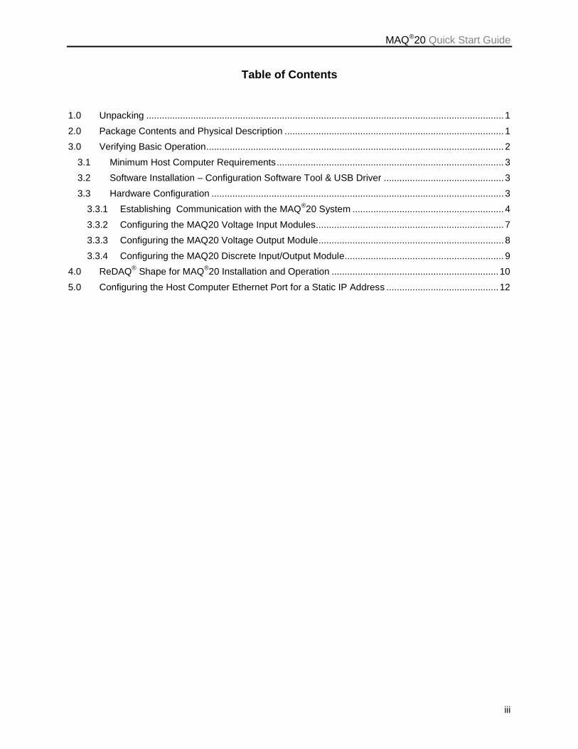
Table of Contents
1.0 Unpacking ......................................................................................................................................... 1
2.0 Package Contents and Physical Description .................................................................................... 1
3.0 Verifying Basic Operation .................................................................................................................. 2
3.1 Minimum Host Computer Requirements ....................................................................................... 3
3.2 Software Installation – Configuration Software Tool & USB Driver .............................................. 3
3.3 Hardware Configuration ................................................................................................................ 3
3.3.1 Establishing Communication with the MAQ®20 System .......................................................... 4
3.3.2 Configuring the MAQ20 Voltage Input Modules ........................................................................ 7
3.3.3 Configuring the MAQ20 Voltage Output Module ....................................................................... 8
3.3.4 Configuring the MAQ20 Discrete Input/Output Module............................................................. 9
4.0 ReDAQ® Shape for MAQ
®20 Installation and Operation ................................................................ 10
5.0 Configuring the Host Computer Ethernet Port for a Static IP Address ........................................... 12

MAQ®20 Quick Start Guide
iv
About Dataforth Corporation “Our passion at Dataforth Corporation is designing, manufacturing, and marketing the best possible signal conditioning, data acquisition, and data communication products. Our mission is to set new standards of product quality, performance, and customer service.” Dataforth Corporation, with more than a quarter century of experience, is the worldwide leader in Instrument Class
® Industrial Electronics – rugged, high
performance signal conditioning, data acquisition, and data communication products that play a vital role in maintaining the integrity of industrial automation, data acquisition, and quality assurance systems. Our products directly connect to most industrial sensors and protect valuable measurement and control signals and equipment from the dangerous and degrading effects of noise, transient power surges, internal ground loops, and other hazards present in industrial environments. Dataforth spans the globe with more than 50 International Distributors and US Representative Companies. Our customers benefit from a team of over 130 sales people highly trained in the application of precision products for industrial markets. In addition, we have a team of application engineers in our Tucson factory ready to solve any in-depth application questions. Upon receipt of an RFQ or order, our Customer Service Department provides fast one-day delivery information turnaround. We maintain an ample inventory that allows small quantity orders to be shipped from stock. Dataforth operates under an ISO9001:2008 quality management system.
Contacting Dataforth Corporation
Contact Method Contact Information E-Mail:
Technical Support [email protected]
Website: www.dataforth.com
Phone: 520-741-1404 and toll free 800-444-7644
Fax: 520-741-0762
Mail: Dataforth Corporation 3331 E. Hemisphere Loop Tucson, AZ 85706 USA
Errata Sheets Refer to the Technical Support area of Dataforth’s website (www.dataforth.com) for any errata information on this product.
MAQ20®Quick Start Guide
1
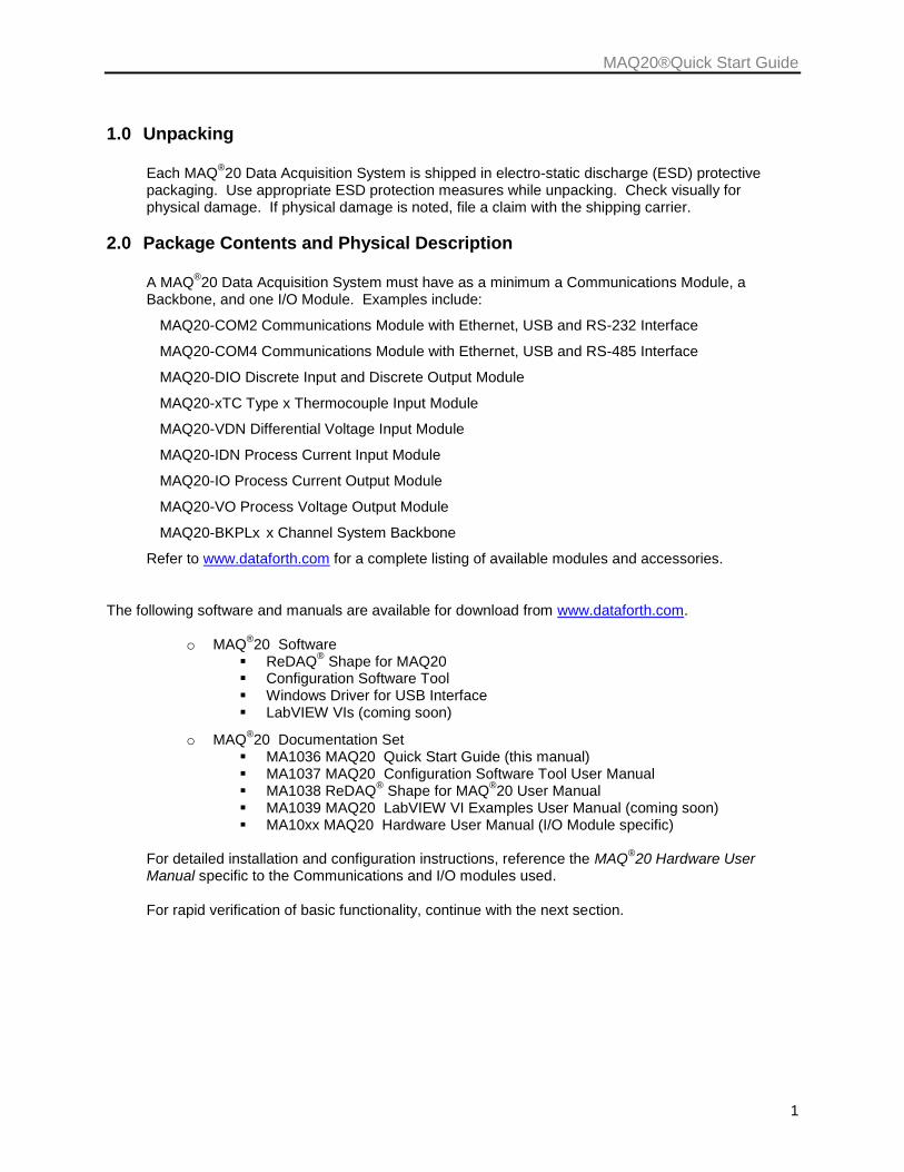
1.0 Unpacking
Each MAQ®20 Data Acquisition System is shipped in electro-static discharge (ESD) protective
packaging. Use appropriate ESD protection measures while unpacking. Check visually for physical damage. If physical damage is noted, file a claim with the shipping carrier.
2.0 Package Contents and Physical Description
A MAQ®20 Data Acquisition System must have as a minimum a Communications Module, a
Backbone, and one I/O Module. Examples include:
MAQ20-COM2 Communications Module with Ethernet, USB and RS-232 Interface
MAQ20-COM4 Communications Module with Ethernet, USB and RS-485 Interface
MAQ20-DIO Discrete Input and Discrete Output Module
MAQ20-xTC Type x Thermocouple Input Module
MAQ20-VDN Differential Voltage Input Module
MAQ20-IDN Process Current Input Module
MAQ20-IO Process Current Output Module
MAQ20-VO Process Voltage Output Module
MAQ20-BKPLx x Channel System Backbone
Refer to www.dataforth.com for a complete listing of available modules and accessories.
The following software and manuals are available for download from www.dataforth.com.
o MAQ®20 Software
ReDAQ® Shape for MAQ20
Configuration Software Tool Windows Driver for USB Interface LabVIEW VIs (coming soon)
o MAQ®20 Documentation Set
MA1036 MAQ20 Quick Start Guide (this manual) MA1037 MAQ20 Configuration Software Tool User Manual MA1038 ReDAQ
® Shape for MAQ
®20 User Manual
MA1039 MAQ20 LabVIEW VI Examples User Manual (coming soon) MA10xx MAQ20 Hardware User Manual (I/O Module specific)
For detailed installation and configuration instructions, reference the MAQ
®20 Hardware User
Manual specific to the Communications and I/O modules used. For rapid verification of basic functionality, continue with the next section.
MAQ®20 Quick Start Guide
2
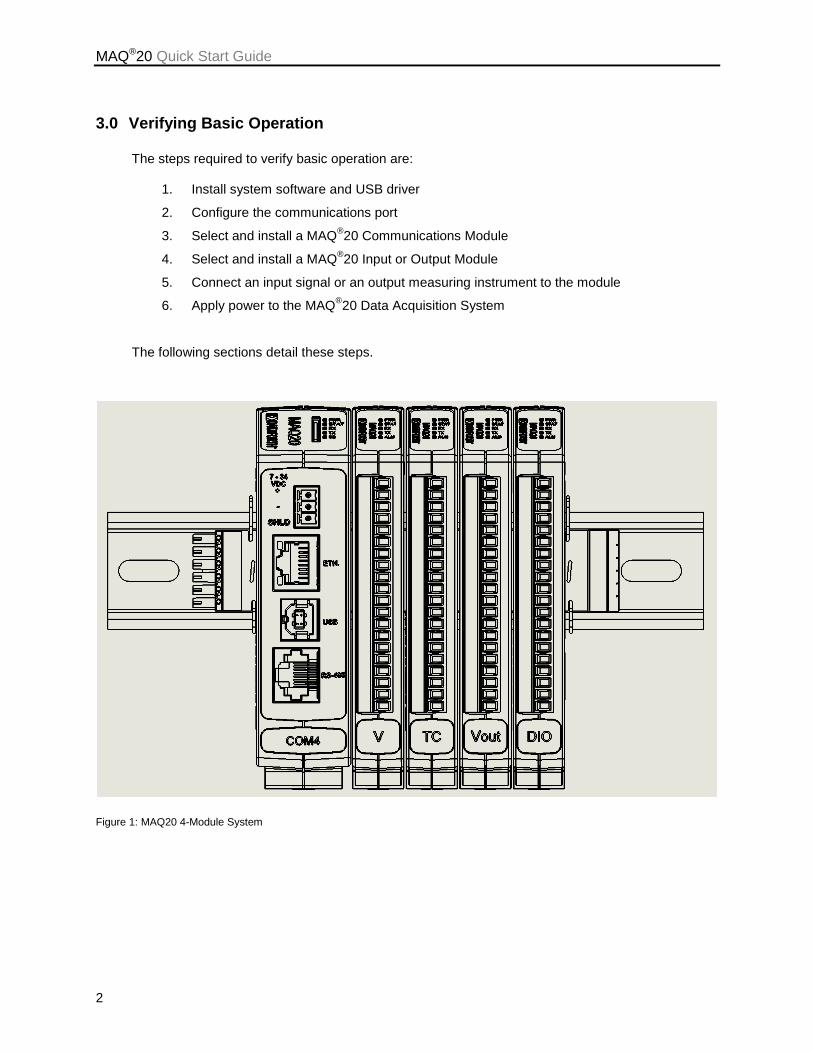
3.0 Verifying Basic Operation
The steps required to verify basic operation are:
1. Install system software and USB driver
2. Configure the communications port
3. Select and install a MAQ®20 Communications Module
4. Select and install a MAQ®20 Input or Output Module
5. Connect an input signal or an output measuring instrument to the module
6. Apply power to the MAQ®20 Data Acquisition System
The following sections detail these steps.
Figure 1: MAQ20 4-Module System
MAQ®20 Quick Start Guide
3
3.1 Minimum Host Computer Requirements
The host computer must be running the Windows 2000, Windows XP, Windows Vista or Windows 7 operating system and must have the minimum hardware to support the operating system. Host Computer Communication Ports:
MAQ20-COM2 based systems interface to a host PC using an Ethernet, USB or RS-232 port.
MAQ20-COM4 based systems interface to a host PC using an Ethernet, USB or RS-485 port.
3.2 Software Installation – Configuration Software Tool & USB Driver
Download the Configuration Software Tool from the Dataforth website, www.dataforth.com
If the system will be used with a USB connection to the host PC, the USB Driver must be installed prior to connecting the system to the computer. Download the driver from www.dataforth.com and follow the installation instructions.
3.3 Hardware Configuration
Install a MAQ®20 backbone into a 35mm DIN rail and then install a MAQ
®20 Communications
Module into the left-most position of the backbone. Install a MAQ®20 Input or Output Module into
one of the open slots in the backbone. Connect an appropriate sensor or calibration signal source to the MAQ
®20 Input Module field connector and/or connect a measurement device to the MAQ
®20
Output Module field connector. Refer to the individual module Hardware Manuals for I/O connection diagrams. Connect the MAQ
®20 Data Acquisition and Control System to the host PC according to the
interface chosen.
USB: Install an SLX147-xx cable (USB type A to type B)
Ethernet: Install an SLX141-Xxx crossover CAT5 cable or an SLX141-xx straight through CAT5 cable. Alternately, obtain an Ethernet switch or hub which is not connected to the enterprise Ethernet, and two SLX141-xx straight through or SLX141-xx crossover CAT5 cables. Connect one CAT5 cable between the host computer Ethernet port and the Ethernet switch or hub, and connect the other CAT5 cable between the MAQ20 and the Ethernet switch or hub.
Serial, RS-232 (MAQ20-COM2): Install an SLXyyy-xx RJ-45 to DB-9 cable for RS-232 communications.
Serial, RS-485 (MAQ20-COM4): Install an SLXyyy-xx RJ-45 to DB-9 cable for RS-485 communications.
Reference the MAQ20-COMx Hardware User Manual for the RS-232 and RS-485 connector pin assignments. The MAQ20-COMx factory default configuration for RS-232 and RS-485 communications is 115.2kbps, 8 data bits, 1 stop bit, even parity, Slave ID 31.

MAQ®20 Quick Start Guide
4
3.3.1 Establishing Communication with the MAQ®20 System
IMPORTANT: If the MAQ®20 system is to be used with a USB connection to the host computer,
ensure that the USB driver provided on the Dataforth website has been installed before connecting the system to the host computer. Refer to Section 3.2 for details. Apply power the MAQ
®20 system and ensure it is connected to the host computer over the
interface chosen. Double click the MAQ20 Config SW Tool icon on the desktop. Once started, the initial screen displays with the View Pane disabled, indicating that the application is not yet connected to the MAQ
®20 system, reference Figure 2.
Figure 2: MAQ20 Configuration Software Tool Window, View Pane Disabled
MAQ®20 Quick Start Guide
5
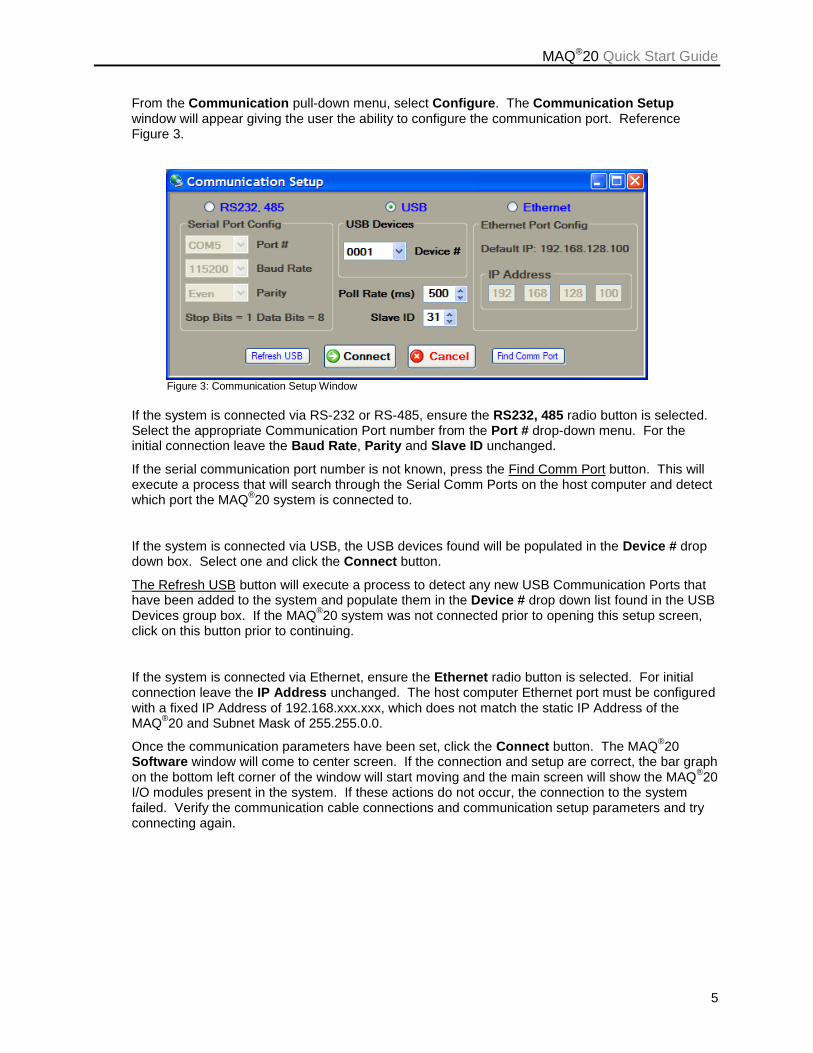
From the Communication pull-down menu, select Configure. The Communication Setup window will appear giving the user the ability to configure the communication port. Reference Figure 3.
Figure 3: Communication Setup Window
If the system is connected via RS-232 or RS-485, ensure the RS232, 485 radio button is selected. Select the appropriate Communication Port number from the Port # drop-down menu. For the initial connection leave the Baud Rate, Parity and Slave ID unchanged.
If the serial communication port number is not known, press the Find Comm Port button. This will execute a process that will search through the Serial Comm Ports on the host computer and detect which port the MAQ
®20 system is connected to.
If the system is connected via USB, the USB devices found will be populated in the Device # drop down box. Select one and click the Connect button.
The Refresh USB button will execute a process to detect any new USB Communication Ports that have been added to the system and populate them in the Device # drop down list found in the USB Devices group box. If the MAQ
®20 system was not connected prior to opening this setup screen,
click on this button prior to continuing.
If the system is connected via Ethernet, ensure the Ethernet radio button is selected. For initial connection leave the IP Address unchanged. The host computer Ethernet port must be configured with a fixed IP Address of 192.168.xxx.xxx, which does not match the static IP Address of the MAQ
®20 and Subnet Mask of 255.255.0.0.
Once the communication parameters have been set, click the Connect button. The MAQ®20
Software window will come to center screen. If the connection and setup are correct, the bar graph on the bottom left corner of the window will start moving and the main screen will show the MAQ
®20
I/O modules present in the system. If these actions do not occur, the connection to the system failed. Verify the communication cable connections and communication setup parameters and try connecting again.
MAQ®20 Quick Start Guide
6
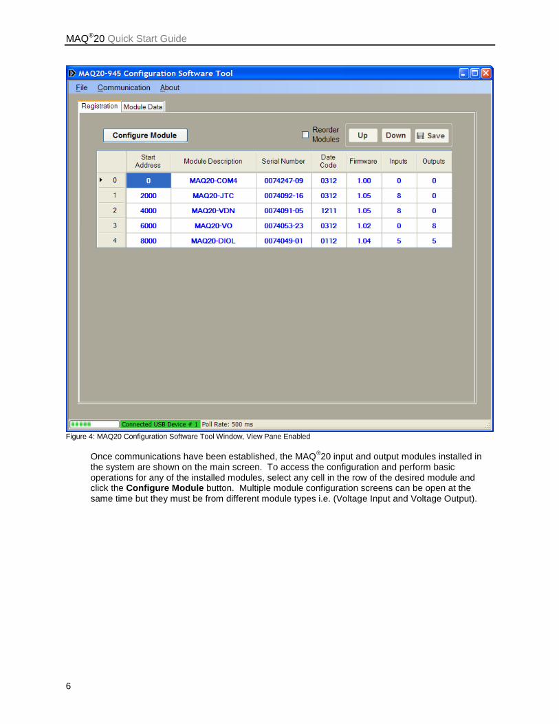
Figure 4: MAQ20 Configuration Software Tool Window, View Pane Enabled
Once communications have been established, the MAQ
®20 input and output modules installed in
the system are shown on the main screen. To access the configuration and perform basic operations for any of the installed modules, select any cell in the row of the desired module and click the Configure Module button. Multiple module configuration screens can be open at the same time but they must be from different module types i.e. (Voltage Input and Voltage Output).
MAQ®20 Quick Start Guide
7
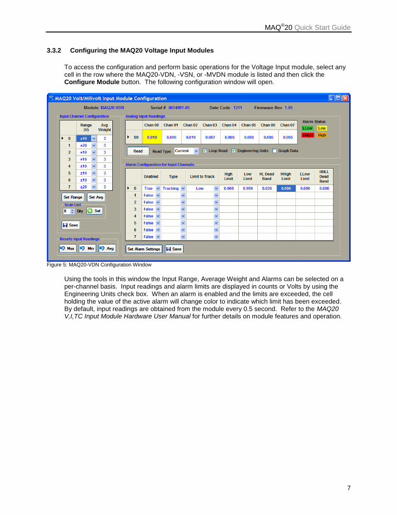
3.3.2 Configuring the MAQ20 Voltage Input Modules
To access the configuration and perform basic operations for the Voltage Input module, select any cell in the row where the MAQ20-VDN, -VSN, or -MVDN module is listed and then click the Configure Module button. The following configuration window will open.
Figure 5: MAQ20-VDN Configuration Window
Using the tools in this window the Input Range, Average Weight and Alarms can be selected on a per-channel basis. Input readings and alarm limits are displayed in counts or Volts by using the Engineering Units check box. When an alarm is enabled and the limits are exceeded, the cell holding the value of the active alarm will change color to indicate which limit has been exceeded. By default, input readings are obtained from the module every 0.5 second. Refer to the MAQ20 V,I,TC Input Module Hardware User Manual for further details on module features and operation.
MAQ®20 Quick Start Guide
8
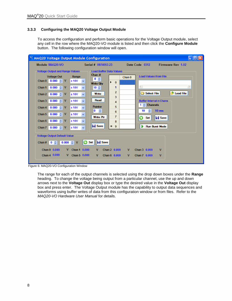
3.3.3 Configuring the MAQ20 Voltage Output Module
To access the configuration and perform basic operations for the Voltage Output module, select any cell in the row where the MAQ20-VO module is listed and then click the Configure Module button. The following configuration window will open.
Figure 6: MAQ20-VO Configuration Window
The range for each of the output channels is selected using the drop down boxes under the Range heading. To change the voltage being output from a particular channel, use the up and down arrows next to the Voltage Out display box or type the desired value in the Voltage Out display box and press enter. The Voltage Output module has the capability to output data sequences and waveforms using buffer writes of data from this configuration window or from files. Refer to the MAQ20-VO Hardware User Manual for details.
MAQ®20 Quick Start Guide
9
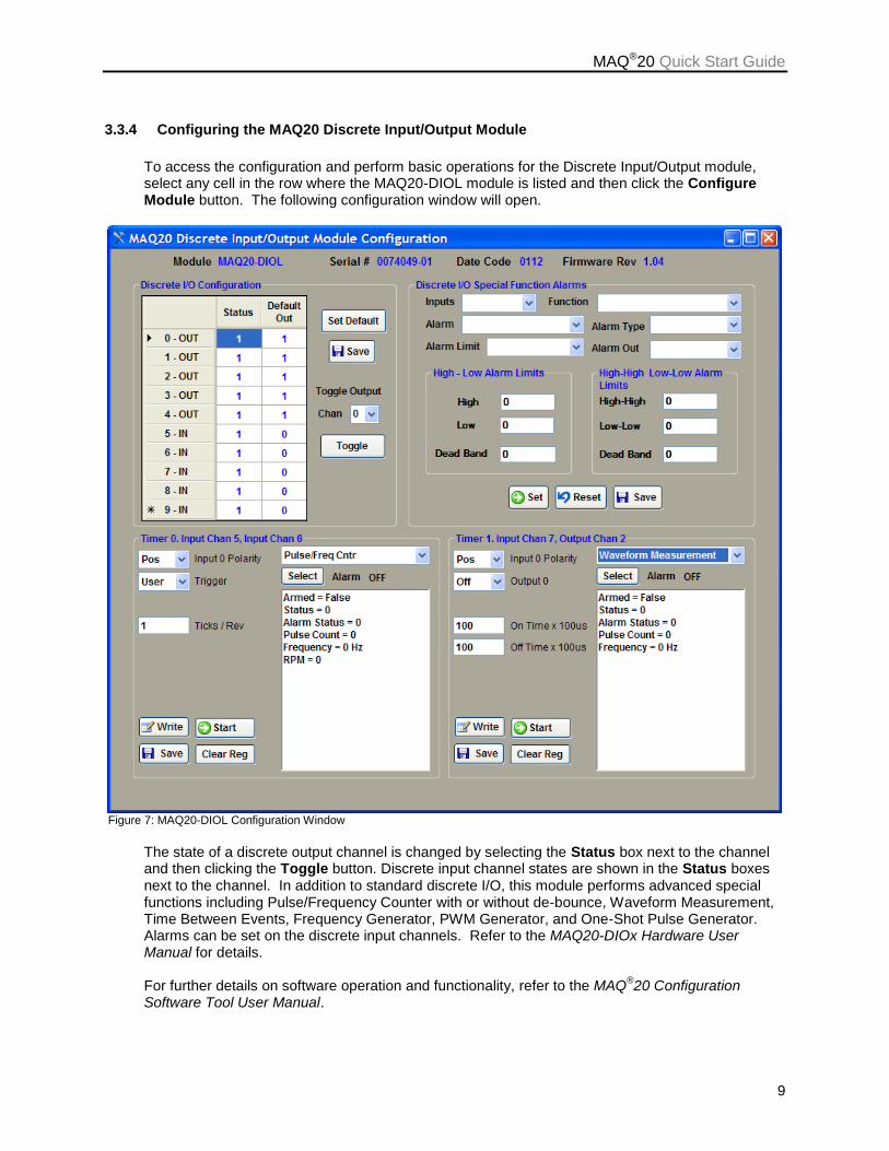
3.3.4 Configuring the MAQ20 Discrete Input/Output Module
To access the configuration and perform basic operations for the Discrete Input/Output module, select any cell in the row where the MAQ20-DIOL module is listed and then click the Configure Module button. The following configuration window will open.
Figure 7: MAQ20-DIOL Configuration Window
The state of a discrete output channel is changed by selecting the Status box next to the channel and then clicking the Toggle button. Discrete input channel states are shown in the Status boxes next to the channel. In addition to standard discrete I/O, this module performs advanced special functions including Pulse/Frequency Counter with or without de-bounce, Waveform Measurement, Time Between Events, Frequency Generator, PWM Generator, and One-Shot Pulse Generator. Alarms can be set on the discrete input channels. Refer to the MAQ20-DIOx Hardware User Manual for details.
For further details on software operation and functionality, refer to the MAQ
®20 Configuration
Software Tool User Manual.

MAQ®20 Quick Start Guide
10
4.0 ReDAQ® Shape for MAQ®20 Installation and Operation
Download the ReDAQ® Shape for MAQ
®20 Developer version User version software from the
Dataforth website, www.dataforth.com.
If the system will be used with a USB connection to the host PC, the USB Driver must be installed prior to connecting the system to the computer. Download the driver from www.dataforth.com and follow the installation instructions.
After installation has completed, double click the blue ReDAQ Shape icon on the desktop. When the software starts up, the Acquire Panel and the MAQ20-System tab will be selected.
Figure 8: Start up window, ReDAQ Shape for MAQ20
If the system is connected via USB, ensure the USB Port radio button is selected.
If the system is connected via RS-232 or RS-485, ensure the Serial Port radio button is selected. Select the appropriate Communication Port number from the drop-down menu. For the initial connection leave the Baud Rate, Parity and Slave ID unchanged.
If the serial communication port number is not known, press the New Ports: Search button. This will execute a process that will search through the Serial Comm Ports on the host computer and detect which port the MAQ
®20 system is connected to.
MAQ®20 Quick Start Guide
11
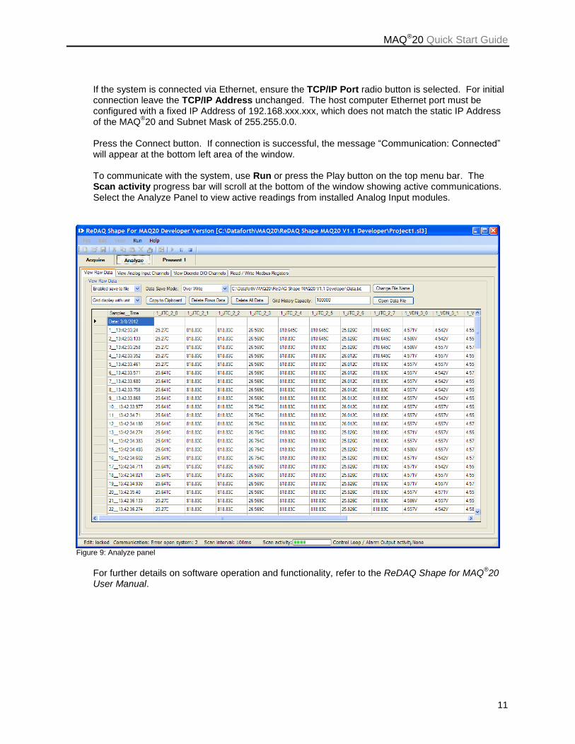
If the system is connected via Ethernet, ensure the TCP/IP Port radio button is selected. For initial connection leave the TCP/IP Address unchanged. The host computer Ethernet port must be configured with a fixed IP Address of 192.168.xxx.xxx, which does not match the static IP Address of the MAQ
®20 and Subnet Mask of 255.255.0.0.
Press the Connect button. If connection is successful, the message “Communication: Connected” will appear at the bottom left area of the window. To communicate with the system, use Run or press the Play button on the top menu bar. The Scan activity progress bar will scroll at the bottom of the window showing active communications. Select the Analyze Panel to view active readings from installed Analog Input modules.
Figure 9: Analyze panel
For further details on software operation and functionality, refer to the ReDAQ Shape for MAQ
®20
User Manual.
MAQ®20 Quick Start Guide
12
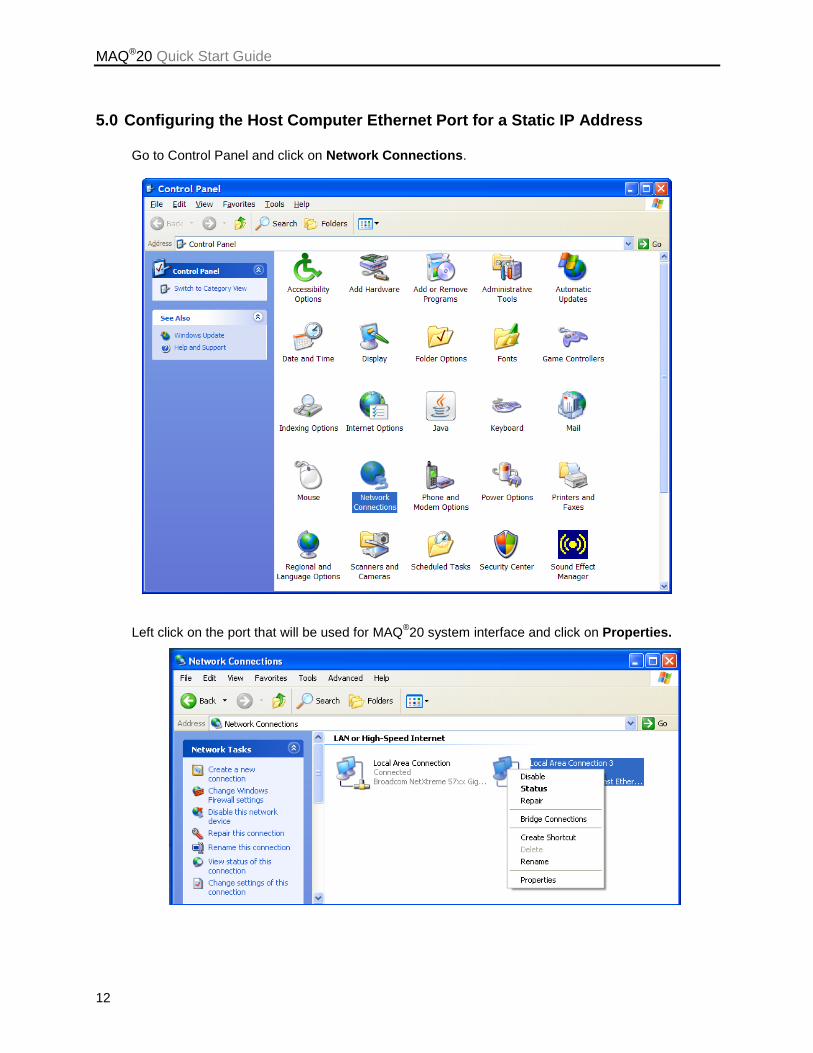
5.0 Configuring the Host Computer Ethernet Port for a Static IP Address
Go to Control Panel and click on Network Connections.
Left click on the port that will be used for MAQ®20 system interface and click on Properties.
MAQ®20 Quick Start Guide
13
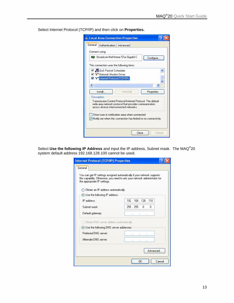
Select Internet Protocol (TCP/IP) and then click on Properties.
Select Use the following IP Address and input the IP address, Subnet mask. The MAQ®20
system default address 192.168.128.100 cannot be used.
MAQ®20 Quick Start Guide
14
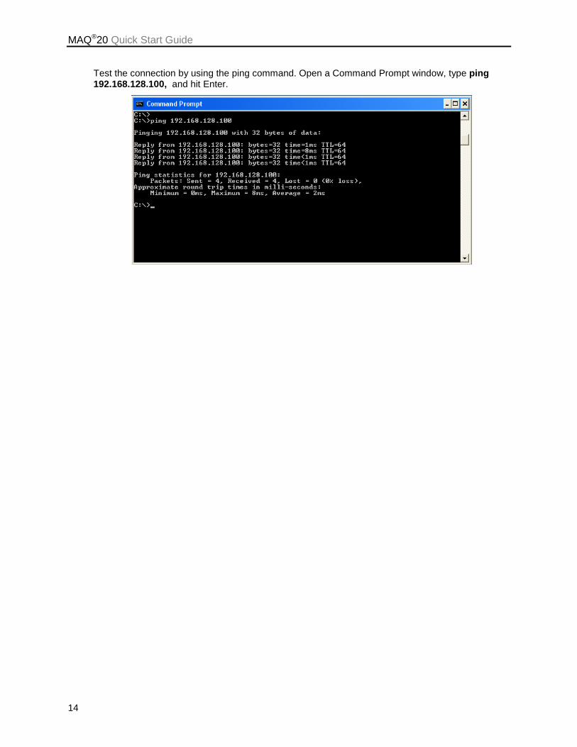
Test the connection by using the ping command. Open a Command Prompt window, type ping 192.168.128.100, and hit Enter.
MAQ®20 Quick Start Guide
15
DATAFORTH WARRANTY Applying to Products Sold by Dataforth Corporation
a. General. Dataforth Corporation (“Dataforth”)
warrants that its products furnished under this Agreement will, at the time of delivery, be free from defects in material and workmanship and will conform to Dataforth's applicable specifications or, if appropriate, to buyer's specifications accepted in writing by Dataforth. DATAFORTH'S OBLIGATION OR LIABILITY TO BUYER FOR PRODUCTS WHICH DO NOT CONFORM TO THE ABOVE STATED WARRANTY SHALL BE LIMITED TO DATAFORTH, AT DATAFORTH'S SOLE DISCRETION, EITHER REPAIRING, REPLACING, OR REFUNDING THE PURCHASE PRICE OF THE DEFECTIVE PRODUCT(S) PROVIDED THAT WRITTEN NOTICE OF SAID DEFECT IS RECEIVED BY DATAFORTH WITHIN THE TIME PERIODS SET FORTH BELOW: i. for all software products including licensed programs, thirty (30) days from date of initial delivery; ii. for all hardware products including complete systems, one (1) year from date of initial delivery; iii. for all special products, sixty (60) days from date of initial delivery; and further, all products warranted hereunder for which Dataforth has received timely notice of nonconformance must be returned FOB to Dataforth's plant in Tucson, Arizona USA within thirty (30) days after the expiration of the warranty periods set forth above. The foregoing warranties shall not apply to any products which Dataforth determines have, by buyer or otherwise, been subjected to operating and/or environmental conditions in excess of the maximum value established therefor in the applicable specifications, or any products that have been the subject of mishandling, misuse, misapplication, neglect, improper testing, repair, alteration or damage. THE PROVISIONS OF THE FOREGOING WARRANTIES EXTEND TO BUYER ONLY AND NOT TO BUYER'S CUSTOMERS OR USERS OF BUYER'S PRODUCTS. THE DATAFORTH STANDARD WARRANTY IS IN LIEU OF ALL WARRANTIES OF MERCHANTABILITY AND FITNESS FOR A PARTICULAR PURPOSE OR USE AND ALL OTHER WARRANTIES WHETHER EXPRESS, IMPLIED OR STATUTORY, EXCEPT AS TO TITLE. THE DATAFORTH STANDARD WARRANTY MAY BE CHANGED BY DATAFORTH WITHOUT NOTICE. b. Buyer Indemnity. Buyer agrees to indemnify and
hold Dataforth harmless from and against any and all claims, damages and liabilities whatsoever asserted by any person, entity, industry organization,
government, or governmental agency of any country resulting directly or indirectly (i) from any acts not authorized by Dataforth in writing or any statements regarding the products inconsistent with Dataforth's product documentation or standard warranty, or (ii) from any breach or threatened breach by buyer, or by any of its employees or agents, of any term, condition or provision of this Warranty or (iii) from any warranty, representation, covenant or obligation given by buyer to any third party and not expressly provided for in this Warranty or (iv) for any non-compliance (in any form) of the products with any necessary or mandatory applicable laws, regulations, procedures, government or industry policies or requirements related to the use, sale or importation of the products. Such indemnification shall include the payment of all reasonable attorneys' fees and other costs incurred by Dataforth in defending such claim. c. Limitation on Damages.
(1) IN NO EVENT SHALL DATAFORTH, ITS SUPPLIERS, LICENSORS, SERVICE PROVIDERS, EMPLOYEES, AGENTS, OFFICERS, AND DIRECTORS BE LIABLE FOR INDIRECT, SPECIAL, INCIDENTAL, COVER, ECONOMIC, PUNITIVE, ACTUAL, EXEMPLARY, CONSEQUENTIAL OR OTHER DAMAGES OF ANY NATURE INCLUDING, WITHOUT LIMITATION, LOST PROFITS OR REVENUES, COSTS OF REPLACEMENT PRODUCTS, LOSS OR DAMAGE TO DATA ARISING OUT OF THE USE OR INABILITY TO USE ANY DATAFORTH PRODUCT. (2) IN NO EVENT SHALL DATAFORTH BE LIABLE FOR DIRECT, SPECIAL, INDIRECT, INCIDENTAL OR CONSEQUENTIAL DAMAGES OF ANY NATURE RESULTING FROM BUYER’S NONCOMPLIANCE (IN ANY FORM) WITH ALL NECESSARY OR MANDATORY APPLICABLE LAWS, REGULATIONS, PROCEDURES, GOVERNMENT POLICIES OR REQUIREMENTS RELATED TO THE USE, SALE OR IMPORTATION OF PRODUCTS. (3) IN NO EVENT WILL THE COLLECTIVE LIABILITY OF DATAFORTH AND ITS SUPPLIERS, LICENSORS, SERVICE PROVIDERS, EMPLOYEES, AGENTS, OFFICERS, AND DIRECTORS TO ANY PARTY (REGARDLESS OF THE FORM OF ACTION, WHETHER BASED UPON WARRANTY, CONTRACT, TORT, OR OTHERWISE) EXCEED THE GREATER OF EITHER US$1000.00 (ONE THOUSAND DOLLARS U.S.A. CURRENCY) OR THE AMOUNT PAID TO DATAFORTH FOR THE APPLICABLE PRODUCT OR SERVICE OUT OF WHICH LIABILITY AROSE.
MAQ®20 Quick Start Guide
16
(4) DATAFORTH’S LIABILITY ARISING OUT OF THE PRODUCTION, SALE OR SUPPLY OF PRODUCTS OR THEIR USE OR DISPOSITION, WHETHER BASED UPON WARRANTY, CONTRACT, TORT OR OTHERWISE, SHALL NOT EXCEED THE GREATER OF EITHER US$1000.00 (ONE THOUSAND DOLLARS U.S.A. CURRENCY) OR THE ACTUAL PURCHASE PRICE PAID BY BUYER FOR DATAFORTH'S PRODUCTS. DATAFORTH'S LIABILITY FOR ANY CLAIM OF ANY KIND SHALL IN NO CASE EXCEED THE OBLIGATION OR LIABILITY SPECIFIED IN THIS WARRANTY. d. Technical Assistance. Dataforth 's Warranty as
hereinabove set forth shall not be enlarged, diminished or affected by, and no obligation or liability shall arise or grow out of, Dataforth's rendering of technical advice, facilities or service in connection with buyer's order of the products furnished hereunder. e. Warranty Procedures. Buyer shall notify
Dataforth of any products which it believes to be defective during the applicable warranty period and which are covered by the Warranty set forth above. Buyer shall not return any products for any reason without the prior authorization of Dataforth and issuance of a Return Material Authorization ("RMA") number. After issuance of a RMA number, such products shall be promptly returned by buyer (and in no event later than thirty (30) days after the Warranty expiration date), transportation and insurance prepaid, to Dataforth's designated facility for examination and testing. Dataforth shall either repair or replace any such products found to be so defective and promptly return such products to buyer, transportation and insurance prepaid. Should Dataforth's examination and testing not disclose any defect covered by the foregoing Warranty, Dataforth
shall so advise buyer and dispose of or return the products in accordance with buyer's instructions and at buyer's sole expense, and buyer shall reimburse Dataforth for testing expenses incurred at Dataforth's then current repair rates. f. Repair Warranty. Dataforth warrants its repair
work and/or replacement parts for a period of ninety (90) days from receipt by buyer of the repaired or replaced products or for the remainder of the warranty period for the initial delivery of such order as set forth in paragraph a above, whichever is greater. g. Critical Applications. Certain applications using
Dataforth's products may involve potential risks of death, personal injury, or severe property or environmental damage ("Critical Applications"). DATAFORTH'S PRODUCTS ARE NOT DESIGNED, INTENDED, AUTHORIZED, OR WARRANTED TO BE SUITABLE FOR USE IN LIFE-SUPPORT DEVICES OR SYSTEMS, SAFETY EQUIPMENT, NUCLEAR FACILITY APPLICATIONS OR OTHER CRITICAL APPLICATIONS WHERE MALFUNCTION OF THE PRODUCT CAN BE EXPECTED TO RESULT IN PERSONAL INJURY, DEATH OR SEVERE PROPERTY DAMAGE. BUYER USES OR SELLS SUCH PRODUCTS FOR USE IN SUCH CRITICAL APPLICATIONS AT BUYER'S OWN RISK AND AGREES TO DEFEND, INDEMNIFY AND HOLD HARMLESS DATAFORTH FROM ANY AND ALL DAMAGES, CLAIMS, PROCEEDINGS, SUITS OR EXPENSE RESULTING FROM SUCH USE. h. Static Sensitive. Dataforth ships all product in
anti-static packages. Dataforth's Warranty as hereinabove set forth shall not cover warranty repair, replacement, or refund on product or devices damaged by static due to buyer's failure to properly ground.
_____________________________________________________________________________________________
MAQ20®Quick Start Guide
17
Application Support Dataforth provides timely, high-quality product support. Call 1-800-444-7644 TOLL-FREE.
Returns/Repair Policy All warranty and repair requests should be directed to the Dataforth Customer Service Department at (520) 741-1404. If a product return is required, request a Return Material Authorization (RMA) number. You should be ready to provide the following information: 1. Complete product model number. 2. Product serial number. 3. Name, address, and telephone number of person returning product. 4. Special repair instructions. 5. Purchase order number for out-of-warranty repairs. The product should be carefully packaged, making sure the RMA number appears on the outside of the package, and ship prepaid to: Dataforth Corporation 3331 E. Hemisphere Loop Tucson, AZ 85706 USA
The information provided herein is believed to be reliable; however, DATAFORTH assumes no responsibility for inaccuracies or omissions. DATAFORTH assumes no responsibility for the use of this information, and all use of such information shall be entirely at the user's own risk. Application information is intended as suggestions for possible use of the products and not as explicit performance in a specific application. Prices and specifications are subject to change without notice. No patent rights or licenses to any of the circuits described herein are implied or granted to any third party. DATAFORTH does not authorize or warrant any DATAFORTH product for use in life support devices and/or systems.
MAQ®20 Industrial Data Acquisition and Control System Quick Start Guide
MA1036 Rev. B – May 2012 © 2012 Dataforth Corporation. All Rights Reserved. ISO9001:2008-Registered QMS