Embed Size (px)
Citation preview
Maps as Numbers 9/16/2014
M. Helper, GEO 327G/386G, UT Austin 1
M. Helper, 9/16/2014 GEO327G/386G, UT Austin 1
Maps as Numbers: Data Models
vertices
nodes
arcs S
E
E
S
E
E
S S
S – Start node
E – End node
Conceptual Models
Reality
Logical Models
Physical Models
9/16/2014 GEO327G/386G, UT Austin 2
The Task
An accurate, registered, digital map that can be
queried and analyzed.
Translate:
Real World, Paper Map Computer Files
Spatial Data Models, Topology
Entity Info. Queriable Database Files
Relational or Object-Oriented Databases
Relate Spatial Coordinates to Entity Info.
“Spatial DBMS” software = GIS software!
9/16/2014 GEO327G/386G, UT Austin 3
Data Models
How is reality abstracted and codified?
Wells are points, rock units are polygons (both are objects)
Well A penetrates Fm. 1; produces oil. Well B penetrates Fm. 3; produces gas. Fm 3 overlies Fm. 1.
Store well locations with a particular file structure, production stats. in a dBase table. Associate table with location.
Wells produce from rocks that contain oil and gas
Conceptual Models
Reality
Logical Models
Physical Models
Co
dificatio
n
Ab
straction
9/16/2014 GEO327G/386G, UT Austin 4
Characterized all features or phenomenon as:
Discrete objects; e.g. wells, roads, rock bodies, etc.
Object-based models
Continuous phenomena; e.g. gravity, magnetic
intensity, topography, temperature, snowfall, soil pH, etc.
Field-based models
Conceptual Models
Maps as Numbers 9/16/2014
M. Helper, GEO 327G/386G, UT Austin 2
9/16/2014 GEO327G/386G, UT Austin 5
VECTOR MODEL
Discrete objects are represented by points and vectors, continuous fields by irregular tessellations of triangles (TINs)
RASTER MODEL Discrete objects and continuous fields are
represented by an array of square cells (pixels)
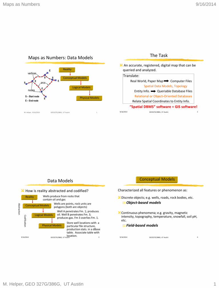
Logical Models
9/16/2014 GEO327G/386G, UT Austin 6
How should discrete objects be coded?
Raster Model Vector Model
Logical Models
9/16/2014 GEO327G/386G, UT Austin 7
Vector Model
AREAS
(Polygons)
consisting of… LINES
(Arcs)
consisting of…
POINTS consisting of…
COORDINATES
(x, y)
(1, 5)
(5, 1)
(7, 2)
(5, 7)
(3, 8)
Logical Models
9/16/2014 GEO327G/386G, UT Austin 8
Continuous phenomena as surfaces
Raster Topography Regular
tessellations, e.g. DEM
Vector Topography Irregular
tessellations, e.g. T.I.N.
Logical Models
Maps as Numbers 9/16/2014
M. Helper, GEO 327G/386G, UT Austin 3
9/16/2014 GEO327G/386G, UT Austin 9
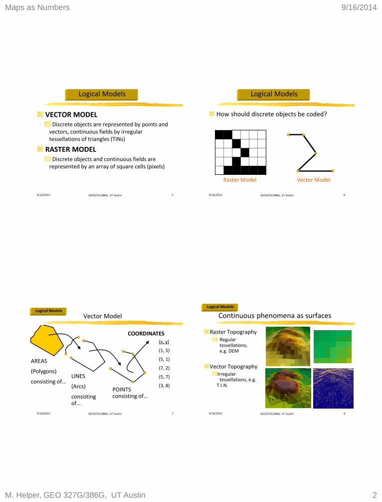
Simple Vector Data Structure
P1 P2
P3
P4 P5
Vector Line Table of Points
(in UTM coordinates)
ID X Y
P1 503200 3200522
P2 503250 3200522
P3 503300 3200460
P4 503245 3200410
P5 503350 3200410
Physical Models
9/16/2014 GEO327G/386G, UT Austin 10
Simple Raster Data Structure:
1 1 0 0 0 0
0 0 1 0 0 0
0 0 0 1 0 0
0 0 1 0 0 0
0 1 1 1 1 1
Raster Line Equivalent Binary Flat File
Physical Models
9/16/2014 GEO327G/386G, UT Austin 11
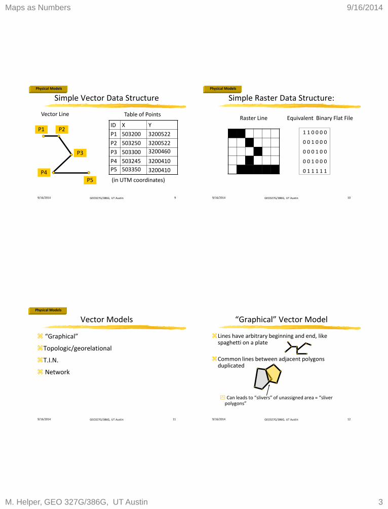
Vector Models
“Graphical”
Topologic/georelational
T.I.N.
Network
Physical Models
9/16/2014 GEO327G/386G, UT Austin 12
Lines have arbitrary beginning and end, like spaghetti on a plate
Common lines between adjacent polygons duplicated
Can leads to “slivers” of unassigned area = “sliver
polygons”
“Graphical” Vector Model
Maps as Numbers 9/16/2014
M. Helper, GEO 327G/386G, UT Austin 4
9/16/2014 GEO327G/386G, UT Austin 13
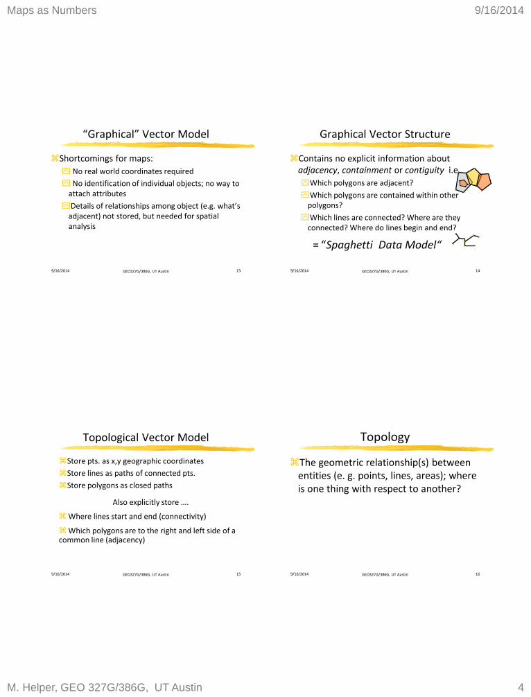
Shortcomings for maps:
No real world coordinates required
No identification of individual objects; no way to attach attributes
Details of relationships among object (e.g. what’s adjacent) not stored, but needed for spatial analysis
“Graphical” Vector Model
9/16/2014 GEO327G/386G, UT Austin 14
Graphical Vector Structure
Contains no explicit information about adjacency, containment or contiguity i.e.
Which polygons are adjacent?
Which polygons are contained within other polygons?
Which lines are connected? Where are they connected? Where do lines begin and end?
= “Spaghetti Data Model“
9/16/2014 GEO327G/386G, UT Austin 15
Topological Vector Model
Store pts. as x,y geographic coordinates
Store lines as paths of connected pts.
Store polygons as closed paths
Also explicitly store ….
Where lines start and end (connectivity)
Which polygons are to the right and left side of a common line (adjacency)
9/16/2014 GEO327G/386G, UT Austin 16
Topology
The geometric relationship(s) between entities (e. g. points, lines, areas); where is one thing with respect to another?
Maps as Numbers 9/16/2014
M. Helper, GEO 327G/386G, UT Austin 5
9/16/2014 GEO327G/386G, UT Austin 17
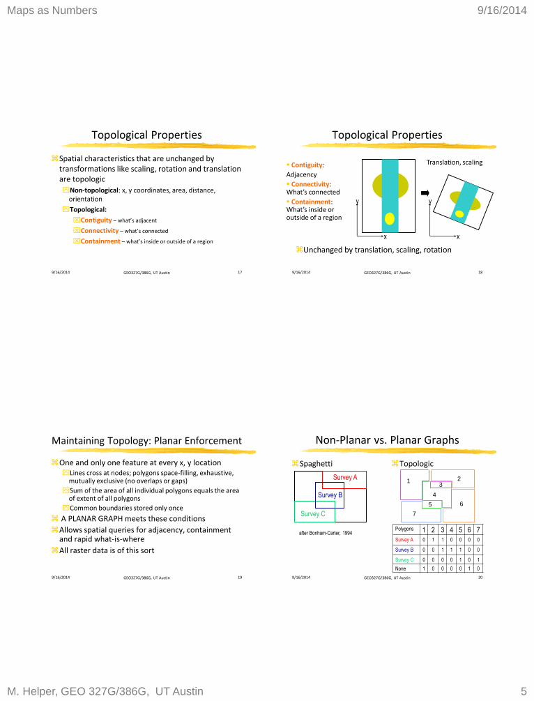
Topological Properties
Spatial characteristics that are unchanged by transformations like scaling, rotation and translation are topologic
Non-topological: x, y coordinates, area, distance, orientation
Topological:
Contiguity – what’s adjacent
Connectivity – what’s connected
Containment – what’s inside or outside of a region
9/16/2014 GEO327G/386G, UT Austin 18
Topological Properties
y
x
y
x
Translation, scaling Contiguity:
Adjacency
Connectivity: What’s connected
Containment: What’s inside or outside of a region
Unchanged by translation, scaling, rotation
9/16/2014 GEO327G/386G, UT Austin 19
Maintaining Topology: Planar Enforcement
One and only one feature at every x, y location Lines cross at nodes; polygons space-filling, exhaustive,
mutually exclusive (no overlaps or gaps)
Sum of the area of all individual polygons equals the area of extent of all polygons
Common boundaries stored only once
A PLANAR GRAPH meets these conditions
Allows spatial queries for adjacency, containment and rapid what-is-where
All raster data is of this sort
9/16/2014 GEO327G/386G, UT Austin 20
Non-Planar vs. Planar Graphs
Spaghetti Topologic
Survey A
Survey B
Survey C 7
1 2
6
4
3
5
Polygons 1 2 3 4 5 6 7
Survey A 0 1 1 0 0 0 0
Survey B 0 0 1 1 1 0 0
Survey C 0 0 0 0 1 0 1
None 1 0 0 0 0 1 0
after Bonham-Carter, 1994
Maps as Numbers 9/16/2014
M. Helper, GEO 327G/386G, UT Austin 6
9/16/2014 GEO327G/386G, UT Austin 21
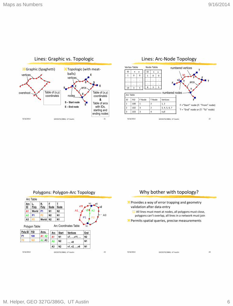
Topologic (with meat- balls)
Lines: Graphic vs. Topologic
Graphic (Spaghetti)
vertices
overshoot Table of (x,y) coordinates
Table of (x,y) coordinates
& Table of arcs
with IDs, starting and
ending nodes
vertices
nodes
arcs S
E
E
S
E
E
S S
S – Start node
E – End node
9/16/2014 GEO327G/386G, UT Austin 22
Lines: Arc-Node Topology
numbered vertices
F
F =“Start” node (F: “From” node)
T = “End” node or (T: “To” node)
ID x y
1 0 0
. . .
. . .
8 3 5
ID x y
1 0 0
. . .
. . .
19 3 5
Arc Table
ID FID F Node T Node Vertices
1 100 1 2 1, 2
2 102 3 2 3, 4, 5, 6, 7
3 103 3 4 null
numbered nodes
Vertex Table Node Table
arcs F
T
T
T
T
F F V1
n2
9/16/2014 GEO327G/386G, UT Austin 23
Polygons: Polygon-Arc Topology
A3 P1 P2
A1 A2
Arc
ID
L.
Poly
R.
Poly
F
Node
T
Node
A1 World P1 N1 N2
A2 P1 P2 N2 N1
A3 P2 World N2 N1
Arc Table
Poly ID FID Arcs.
P1 100 A1, A2
P2 102 A2, A3
Polygon Table
Arc Start Vertices End
A1 N1 v7, …,v11, … N2
A2 N2 …, v8 N1
A3 N2 v1, v2, …,v6 N1
v1 v2
v8
v11
N1
N2
Arc Coordinates Table
9/16/2014 GEO327G/386G, UT Austin 24
Why bother with topology?
Provides a way of error trapping and geometry validation after data entry
All lines must meet at nodes, all polygons must close, polygons can’t overlap, all lines in a network must join
Permits spatial queries, precise measurements
Maps as Numbers 9/16/2014
M. Helper, GEO 327G/386G, UT Austin 7
9/16/2014 GEO327G/386G, UT Austin 25
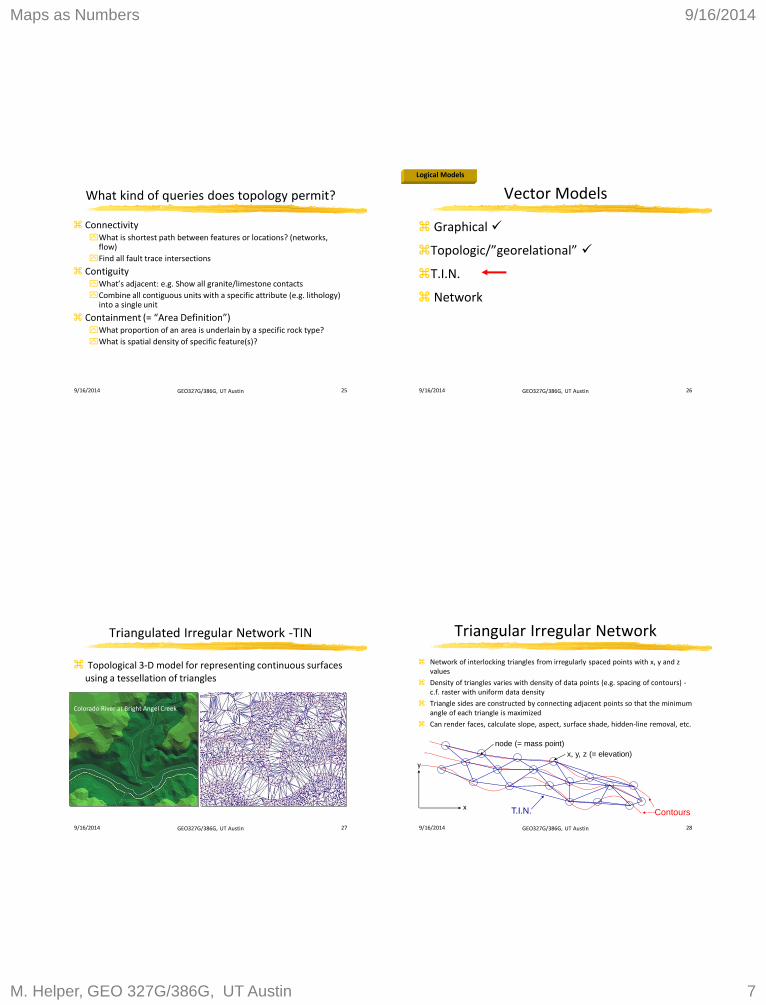
What kind of queries does topology permit?
Connectivity What is shortest path between features or locations? (networks,
flow)
Find all fault trace intersections
Contiguity What’s adjacent: e.g. Show all granite/limestone contacts
Combine all contiguous units with a specific attribute (e.g. lithology) into a single unit
Containment (= “Area Definition”) What proportion of an area is underlain by a specific rock type?
What is spatial density of specific feature(s)?
9/16/2014 GEO327G/386G, UT Austin 26
Vector Models
Graphical
Topologic/”georelational”
T.I.N.
Network
Logical Models
9/16/2014 GEO327G/386G, UT Austin 27
Triangulated Irregular Network -TIN
Topological 3-D model for representing continuous surfaces using a tessellation of triangles
Colorado River at Bright Angel Creek
9/16/2014 GEO327G/386G, UT Austin 28
Triangular Irregular Network
Network of interlocking triangles from irregularly spaced points with x, y and z values
Density of triangles varies with density of data points (e.g. spacing of contours) - c.f. raster with uniform data density
Triangle sides are constructed by connecting adjacent points so that the minimum angle of each triangle is maximized
Can render faces, calculate slope, aspect, surface shade, hidden-line removal, etc.
Contours T.I.N.
y
x
x, y, z (= elevation)
node (= mass point)
Maps as Numbers 9/16/2014
M. Helper, GEO 327G/386G, UT Austin 8
9/16/2014 GEO327G/386G, UT Austin 29
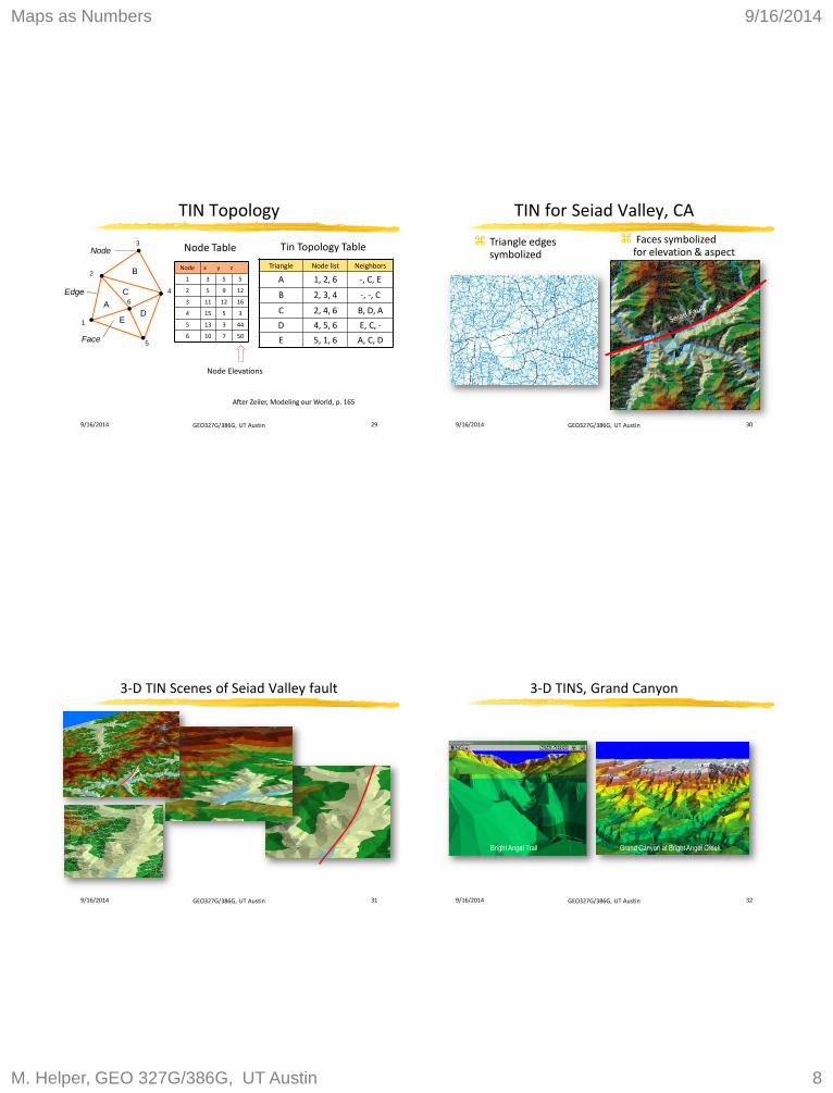
TIN Topology
After Zeiler, Modeling our World, p. 165
Triangle Node list Neighbors
A 1, 2, 6 -, C, E
B 2, 3, 4 -, -, C
C 2, 4, 6 B, D, A
D 4, 5, 6 E, C, -
E 5, 1, 6 A, C, D
1
2
3
4
5
6 A
B
C
D E
Node
Edge
Face
Tin Topology Table
Node x y z
1 3 5 5
2 5 9 12
3 11 12 16
4 15 5 3
5 13 3 44
6 10 7 50
Node Table
Node Elevations
9/16/2014 GEO327G/386G, UT Austin 30
TIN for Seiad Valley, CA
Triangle edges symbolized
Faces symbolized for elevation & aspect
9/16/2014 GEO327G/386G, UT Austin 31
3-D TIN Scenes of Seiad Valley fault
9/16/2014 GEO327G/386G, UT Austin 32
3-D TINS, Grand Canyon
Grand Canyon at Bright Angel Creek Bright Angel Trail

Maps as Numbers 9/16/2014
M. Helper, GEO 327G/386G, UT Austin 9
9/16/2014 GEO327G/386G, UT Austin 33
Vector Models
Graphical
Topologic/”georelational”
T.I.N.
Network - not discussed, see Help files
Logical Models