Embed Size (px)
Citation preview
Mapping Temporal ER Diagrams to RelationalSchemas
Heidi Gregersen, Leo Mark, and Christian S. Jensen
December 4, 1998
TR-39
A TIMECENTER Technical Report
Title Mapping Temporal ER Diagrams to Relational Schemas
Copyright c� 1998 Heidi Gregersen, Leo Mark, and Christian S. Jensen.All rights reserved.
Author�s� Heidi Gregersen, Leo Mark, and Christian S. Jensen
Publication History December 1998. A TIMECENTER Technical Report
TIMECENTERParticipants
Aalborg University, DenmarkChristian S. Jensen (codirector), Michael H. B¨ohlen, Renato Busatto, Curtis E. Dyreson,Heidi Gregersen, Dieter Pfoser, SimonasSaltenis, Janne Skyt, Giedrius Slivinskas,Kristian Torp
University of Arizona, USARichard T. Snodgrass (codirector), Kongki Moon, Sudha Ram
Individual participantsAnindya Datta, Georgia Institute of Technology, USAKwang W. Nam, Chungbuk National University, KoreaMario A. Nascimento, State University of Campinas and EMBRAPA, BrazilKeun H. Ryu, Chungbuk National University, KoreaMichael D. Soo, University of South Florida, USAAndreas Steiner, TimeConsult, SwitzerlandVassilis Tsotras, University of California, Riverside, USAJef Wijsen, Vrije Universiteit Brussel, Belgium
For additional information, see The TIMECENTER Homepage:URL: <http://www.cs.auc.dk/research/DBS/tdb/TimeCenter/>
Any software made available viaTIMECENTER is provided “as is” and without any express or implied war-ranties, including, without limitation, the implied warranty of merchantability and fitness for a particular pur-pose.
The TIMECENTER icon on the cover combines two “arrows.” These “arrows” are letters in the so-calledRunealphabet used one millennium ago by the Vikings, as well as by their precedessors and successors. The Runealphabet (second phase) has 16 letters, all of which have angular shapes and lack horizontal lines becausethe primary storage medium was wood. Runes may also be found on jewelry, tools, and weapons and wereperceived by many as having magic, hidden powers.
The two Rune arrows in the icon denote “T” and “C,” respectively.
AbstractMany database applications manage information that varies over time, and most of the database schemas forthese applications were designed using one of the several versions of the Entity-Relationship (ER) model.In the research community as well as in industry, it is common knowledge that temporal aspects of dataare pervasive and important to the applications, but are also difficult to capture using the ER model. Theresearch community has developed temporal ER models, in an attempt to provide modeling constructs thatmore naturally and elegantly support capturing the temporal aspects. Specifically, the temporal modelsprovide enhanced support for capturing aspects such as lifespans, valid time, and transaction time of data.
Because commercial database management systems support neither the ER model nor any temporal ERmodel as a model for data manipulation—but rather support various versions of the relational model forthis purpose—we provide a two-step transformation from temporal ER diagrams, with built-in support forlifespans and valid and transaction time, to relational schemas. The first step of the algorithm translates atemporal ER diagram into relations in a surrogate-based relational target model; and the second step furthertranslates this relational schema into a schema in a lexically-based relational target model.
1 Introduction
A wide range of prominent, existing database applications manage time-varying information. These includefinancial applications such as portfolio management, accounting, and banking; record-keeping applications,including personnel, medical-record, and inventory; and travel applications such as airline, train, and hotelreservations and schedule management.
In the database community temporal aspects of information have been discussed over the years. In thispaper, we will focus on four distinct types of temporal aspects that are candidates for being stored in a database,namelyvalid time, lifespan, transaction time, anduser-defined time[11].
The notion ofvalid timeapplies to facts: the valid time of a fact is the time when the fact is true in the mini-world. All facts have a valid time, but the valid time may or may not be captured explicitly in the database.As an example, consider an Employee entity “E1” with a Department attribute. A valid time of “June 1996”associated with the value “Shipping” represents the fact that “E1 is in Shipping” is valid during June 1996.When valid time is captured in the database for an attribute such as Department, the database is capable ofrecording the varying Department values for the Employee entities. If it is not captured, the database will onlyrecord one (the current) Department value for each Employee entity.
The lifespanof an entity captures the existence time of the entity: the time during which it exists in themodeled mini-world. If lifespans of entities are supported, this means that the model has built-in support forcapturing, in the database, the times when entities exist. The lifespan of a entity “E” may be seen as the validtime of the related fact, “E exists.” However, we choose to consider lifespans as a separate aspect, since therecording of lifespans of entities is essential for many applications. If relationships are regarded as havingexistence in their own right, the concept of lifespan is also applicable to relationships, with the same meaningas for entities.
Thetransaction timeof a database fact is the time when the fact is current in the database. As is the case forlifespans the transaction time of a factF may be seen as the valid time of a related fact, namely the fact, “F iscurrent in the database,” but again we have chosen to record transaction time as a separate aspect. Unlike validtime, transaction time may be associated with any structure stored in a database, not only with facts. Thus, allstructures stored in a database have a transaction-time aspect. Note that the transaction time does not provideinformation about the existence time or the valid time of the structure it is associated with, and that it, like allthe above-mentioned temporal aspects, has a duration.
User-defined timeis supported when time-valued domains for attributes are available in the data model.These are then employed for giving temporal semantics—not captured in the data model, but only externally, inthe application code and by the database designer—to the ER diagrams. For Employee entities, such attributescould record birth dates, hiring dates, etc.
1

One of the temporally extended ER models developed in the research community is the Time Extended ERmodel, TIMEER [9]. This model extends the ER model with annotations for specifying the temporal aspectsthat need to be captured in the underlying data base, and it is the only model that explicitly supports lifespans,valid time, and transaction time. For this reason, we have chosen the TIMEER model as input to the mappingalgorithms presented in this paper.
Several algorithms to construct relational schemas from conceptual schemas already exist, e.g., for the ERmodel [1, 18] and the Extended ER model [7]. These algorithms serve as models for the algorithm presented inthis paper, but do not address temporal aspects, the focus of the present paper. More interestingly, four mappingsfrom temporally extended ER models to the relational model have been previously proposed [8, 13, 14, 17].We consider each algorithm in turn, discussing their specification and their limitations.
The RAKE model [8] provides shorthand notations for indicating valid-time support for attributes and re-lationship types and lifespan support for entity types. The description of the accompanying mapping algorithmconsists of very short informal explanations, accompanied by an example for each of the shorthand notations.The algorithm does not consider transaction time and its combination with other temporal aspects, and it doesnot consider temporal integrity constraints, neither informally nor formally.
The MOTAR model [14] supports valid time and provides new modeling constructs for specifying tempo-ral attributes (periodic and aperiodic) and relationship types. The mapping algorithm is well designed, and itsdescription is somewhat comprehensive. The algorithm produces a relational schema that is at least in third nor-mal form, given a well-designed argument ER diagram. But like the previous mapping, this mapping considersneither transaction time nor any temporal integrity constraints.
The TempEER model [13] supports both valid time and transaction time. Its mapping algorithm is dividedinto two steps: First, the mapping algorithm for the TempEER model [7] is reused, slightly rewritten, though,to create relations. Second, all the relations are extended with timestamp attributes to capture the lifespan ofthe objects stored in the relations. A constraint that limits the lifespans of relationships to be included in thelifespan of the participating entities as well as a constraint that limits the lifespan of an entity in a subclassto be included in the lifespan of the related entity in the superclass are explained, but not formally defined.In contrast, this paper formally defines a comprehensive set of 31 constraints that enforce the ER-specifiedtime-related semantics in the relational context. TempEER’s mapping does accommodate transaction time, butonly a single time point, rather than a pair, is used for capturing the transaction-time duration of a tuple. Thissimplifies the mapping, but also seems to be a somewhat restrictive solution.
Finally, the ERT model [17] supports valid time and has an associated step-wise, precisely formulatedmapping algorithm. The algorithm is well-designed and aims to produce third normal form relational databaseschemas for well-designed argument ERT diagrams. The precise formulation of the steps is a very strongpoint of this algorithm. This algorithm, however, does not consider transaction time, and temporal integrityconstraints.
The present paper’s new contributions are several. It precisely and systematically articulates how temporalER diagrams in the TIMEER model are mapped to a relational platform. This mapping accounts for all thetemporal aspects addressed by the existing dozen of temporal ER models, namely valid and transaction time andlifespans, in addition to all their meaningful combinations. The mapping is accompanied by a comprehensiveset of precisely defined constraints that are necessary to enforce, on a relational platform, the semantics of validand transaction time and lifespans captured in temporal ER diagrams.
The mapping consists of two steps. In Step I, we map the TIMEER model to a surrogate-based relationaltarget model. In Step II, we map this model to a lexically-based relational target model. The mappings arebased on ideas presented in [3, 7]. We use the interval tuple-timestamp scheme to record all the supportedtemporal aspects of data.
There are two reasons for first mapping the TIMEER model to the surrogate-based relational target model.First, the semantics of the surrogate-based relational target model is closer to the semantics of the TIMEERmodel. Second, we believe that future relational models will provide support for surrogate domains as well
2
as temporal domains. Thus, Step I of our mapping meets future needs. Step II of our combined mappingguarantees that our mapping meets today’s needs.
This paper is structured as follows. In Section 2, we define the three models used in this paper. In Section 3,we present the mapping from the TIMEER model to the surrogate-based relational target model. In Section 4,the mapping from this model to the lexically-based relational target model is presented. Finally, in Section 5 asummary and future research directions are presented.
2 Argument and Target Models
In this section we present the three models used in this paper. First, we present the conceptual model TIMEERthat is the argument to the first step of the mapping algorithm. Second, we define the surrogate-based relationalmodel that is the target model of the first step and the argument model to the second step of the mappingalgorithm. Finally, we define the lexically-based relational model, that is the target model of the second step.
2.1 TIMEER
Since its publication, the ER model [2] has had various notations and semantics. It has been extended in orderto capture superclass/subclass relationships and complex entity types, to name a but few extensions, and is thenknown as “the” EER model. The EER model presented by Elmasri and Navathe [7] is chosen as the outset forTIMEER. The reader is assumed to be familiar with that model.
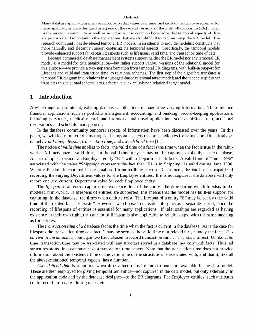
The modeling constructs of the TIMEER model are presented next. The TIMEER model, including itsformal semantics, is described in detail in [9]. The model has implicit temporal support, but the EER constructsand their semantics are retained, i.e., notation and semantics areadded to the EER model to arrive at theTIMEER model. It extends the EER model to better capture, where indicated, temporal aspects of entities,relationships, superclasses/subclasses, and attributes. Figure 1 presents a TIMEER diagram of a companydatabase. We will explain and refer to this diagram throughout this section.
Join_date
Salary BT
Belongs_to
ID
Name
Birth_date
hours/week
Works_forVT
Name
forResponsible
Number
Profit BT
ManagesManager
RankApp_date Type
Project
ID
Budget BT
Income
Expences
Dependent
Dep_of
Relationship
Employee LT
(1,1)(1,N)
(1,1)
(1,1)
(1,N)
Department TT
(1,1)
Location VT
(1,1)
[1,N]
(1,1)
(0,N)
[1,N](1,N)
Name
Figure 1: TIMEER Diagram of a company Database
3
Regular Entity Types
An entity type is represented graphically by a rectangle. Since all entities have an existence time and a transac-tion time aspect, it must be decided for each entity type in a TIMEER diagram whether or not to capture thesetemporal aspects of the entities in the database. Entity types that capture at least one temporal aspect are termedtemporal.
If the lifespan or the transaction time of the entity type is captured, this is indicated by placing a LS or aTT, respectively, in the upper-right corner of the rectangle. If both the lifespan and the transaction time arecaptured, an LT is placed as before.
In Figure 1, we capture both the lifespan and the transaction time of the entity type Employee.
Weak Entity Types
A weak entity type is represented by a double rectangle. Weak entity types represent entities that are existencedependent on entities of other entity types and that cannot by themselves be uniquely identified. A weak entitytype must therefore be related via an identifying relationship type (represented by a double diamond) to one ormore regular entity types that are the owners of the weak entity type. Weak entity types may capture the sametemporal aspects as regular entity types, and their temporal support are independent of the temporal supportspecified for the owner entity types.
In Figure 1, the entity type Dependent is weak and owned by the entity type Employee.
Attributes
Entities are characterized by their attributes. A single-valued attribute is represented by an oval, a multi-valuedattribute is represented by a double oval, and a composite attribute is represented by an oval connected directlyto the components of the composite attribute.
Every attribute has a valid-time and a transaction-time aspect. For each attribute the database designer musttherefor decide to capture these aspects or not.
If the valid time is captured, a VT is placed to the right in the oval; if transaction time is captured, a TT isused. If both valid time and transaction time are captured, a BT (BiTemporal) is placed to the right in the oval.The components of a temporal composite attribute inherit the temporal specification of the composite attribute.
Both temporal and non-temporal entity types can have temporal and non-temporal attributes.In Figure 1, we model that we want to capture the valid time and the transaction time of the Salary of an
Employee.It is required that the the database designer specifies a key for each entity type in the diagram. To indicate
that a set of attributes represents the key of an entity type, the attribute names of the involved attributes areunderlined. Key attributes of an entity type can be specified as temporal or non-temporal. Simple and compositeattributes may be specified as key attribute.
Key attributes can be specified as temporal since the semantics of the TIMEER model ensures that allattribute types are snapshot reducible [15]. This ensures, for example, that a single-valued attribute, at any pointin time, is single-valued. Thus, combining snapshot reducibility [15] of attribute types with the application ofthe conventional key constraint, we have that a key attribute uniquely identifies an entity at any single point intime.
Relationship Types
A relationship type is represented by a diamond. For each relationship type it has to be decided by the databasedesigner whether or not to capture the temporal aspects of the relationships of the relationship type. If sometemporal aspect is captured for a relationship type we term it temporal; otherwise, it is termed non-temporal.
4
Relationships can be seen from two very different points of view. We can perceive relationships amongentities as attributes of the participating entities, or we can perceive relationships as things that exist in theirown right. It is possible to adopt either point of view in TIMEER.
If the relationship is considered as an attribute, it must be specified whether to capture valid time, transactiontime, or both. If valid time or transaction time is captured, this is indicated by placing a VT or a TT in the lowercorner of the diamond. If both valid time and transaction time are captured, a BT is placed in the lower corner.The attribute view is the default view of a relationship, that is, a non-temporal relationship and a temporalrelationship type supporting transaction time only is considered an attribute of the participating entities.
For each relationship type perceived as a thing that exists on its own right, it must be specified whether tocapture the lifespan, or both transaction time and the lifespan. If the lifespan is captured this is indicated by anLS. If both lifespan and transaction time are captured, an LT is used.
In Figure 1, we model that we want to capture the valid time of the relationship Worksfor between Em-ployee and Project.
Snapshot Participation Constrains
The snapshot participation constraint of entity typeE with respect to relationship typeR is represented byplacingmin andmax in parentheses next to the line connecting entity typeE with relationship typeR. Themeaning of this is that at any point in time, each entitye of the entity typeE will participate in at leastmin andat mostmax relationshipsr of R.
In Figure 1, the snapshot participation constraint of type Employee with respect to the relationship typeWorks for is (1,1).
Lifespan Participation Constraint
The snapshot participation constraint described above constrains the participation of the entities at any givenpoint in time. However, it is also useful to be able to constrain the participation of an entity in a relationshipover the existence time of the entity.
The lifespan participation constraint of entity typeE with respect to relationship typeR is represented byplacingmin andmax in square brackets next to the line connecting entity typeE with relationship typeR.The meaning of the lifespan participation constraint is that over all of time, each entitye of the entity typeEwill participate in at leastmin and at mostmax relationshipsr of R.
In Figure 1, the lifespan participation constraint of type Employee with respect to the relationship typeWorks for is [1,N].
Superclasses and Subclasses
The TIMEER model offers support for specifying superclass/subclass relations. The syntax is as in the EERmodel.
A subclass inherits the attributes and the temporal support of its superclass. Is is not possible to changethe temporal support of the inherited attributes, but it is possible to add attributes and to further expand theinherited temporal support of the class itself, i.e., if the inherited temporal support of a subclass is lifespan thenthe temporal support can be expanded to also include transaction time.
2.2 Definition of the Surrogate-Based Relational Target Model
The surrogate-based relational target model is inspired by Codd’sRM/T model [3] and Snodgrass’ TupleTimestamp Scheme [15].
5
Domain of Attributes
In addition to the lexical domains,DD � fD�� D�� � � ��Dng, supported by the standard relational model,the surrogate-based relational target model supports a domain of surrogates [10] called theE-domain, andthree time domains, namely the lifespan domain,DLS , the valid-time domain,DV T , and the transaction-timedomain,DTT . A description of the time domains is given shortly. Surrogates are system-generated uniqueinternal identifiers. Their values cannot be seen by and cannot be modified by the users of the model. Lifespan,valid-time, and transaction-time timestamps are represented aschronon[11] (defined later).
Attributes defined over theE-domainare calledE-attributes, and attributes defined over time domains arecalled time attributes. The names of the time attributes are LSs, LSe, VTs, VTe, TTs, and TTe, where subscripts ande indicates start and end, respectively. The time attributes used to record existence time and valid time forattributes/relationships have values that are subject to user control, whereas the time attributes used to recordtransactions time are under system control and therefore cannot be changed by the users. The names of theattributes defined over the lexical domains come from the setDA � fA�� A�� � � �� Ang.
The database community generally agree that a discrete model of time is adequate, and we will adopt thisview. Thereal time line is described by the baseline clock (BLC) [5], which provides the semantics of thetimestamps. This time line is bounded in both ends, by the “Big Bang” as the lower bound and the “BigCrunch” as the upper bound. The model of time we use is thus a totally ordered, finite set ofchronons, whichis isomorphic to a finite subset of the natural numbers [6]. This may be seen as dividing the real time line intoindivisible segments of equal size. A real-world time instant is expected to be much smaller than a chronon andis represented in the model by the chronon during which it occurs [6]. We will usec to denote chronons. Thesize of the chronons, called the granularity [4], can be specified explicitly.
For all the supported time dimensions, we adopt the above-mentioned model of time. For each dimension,there is several domains of times. Each domain for a time dimension is given byDgranuledimension, where the sizeof the chronons defining the time domain is given bygranule. For the valid-time and the lifespan domains,some chronons are expected to be in the future and some chronons are expected to be in the past. The chrononcnow denotes the chronon representing the current real-time instant, andUC (“until changed”) is a specialtransaction-time marker. If a tuple in a relation recording transaction time has the valueUC of its transaction-time endstamp this means that the tuple is current in the database.
A time interval is defined as the set of time instants between two instants. A time interval is represented bya sequence of consecutive chronons, represented in turn by a starting and an ending chronon. On the above-mentioned time domains, we thus define intervals�ci� cj �
granule whereci is the starting chronon,cj is the termi-nating chronon, and the size of the chronons isgranule. We let�ci� cj �
granulevt � �ci� cj �
granulett � and�ci� cj �
granulels
denote intervals over the valid-time, transaction-time, and the lifespan domains, respectively.We also define temporal elements [11] over time domains. A temporal element is a finite union of intervals
and is denoted byIgranule � �ci� cj �granule� � � � � �ck� cl�
granule. Since any time domainDgranuledimension is discrete
and finite, we can define a temporal element over this time domain as an element of the set�Dgranuledimension . We let
Igranulevt � Igranulett � andIgranulels denote temporal elements over the valid-time, transaction-time, and the lifespandomains, respectively.
Relations
The surrogate-based relational target model has two types of relations,E-relationsand A-relations. An E-relation has a singleE-attributedefined over theE-domainand, depending on the temporal support specifiedfor the corresponding entity type in the TIMEER diagram, a number of time attributes. The set of tuples inanE-relationconstitutes the existence list for the entity type. A surrogate value is never reused for a differentobject. For easier recognition, the names of E-attributes end with the character “ø”, and the names of E-relationsare the names of the entity types they represents. When the temporal support specified for a relationship type
6
includes lifespan, this indicates that relationships of the type are considered to exist in their own right likeentities. Consequently, E-relations represent such relationship types as well.
An A-relation represents attributes of entities. It has anE-attribute which references the E-relation rep-resenting the entity type for which it represents attributes. Single-valued, composite, as well as multi-valuedattributes are represented in A-relations. Depending on the temporal support specified for an attribute, its rep-resenting A-relation also has a number of time attributes.
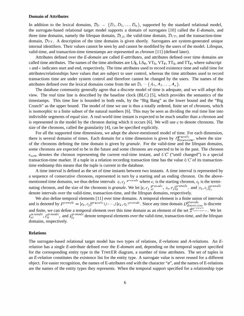
The relations below illustrate the E-relations and A-relations of this model. The E-relationEmployeerepre-sents the entity typeEmployeefrom Figure 1, for which support for lifespan and transaction time are specified.The relation has two tuples representing one employee, and the granularity of the chronons isday. The tuplesalso indicate how we assume relations are updated. Specifically, we assume that a tuple is storing maximaltransaction-time intervals so that each transaction-time chronon in the interval is associated with the samelifespan or valid-time interval. The A-relationEmployeeSalaryrepresents the temporal attributeSalaryfromFigure 1. The temporal support for this attribute includes valid time and transaction time.
Employee Employee Salary
employeeø TTs TTe LSs LSee1 1 8 10 15e1 9 UC 5 20
employeeø Salary TTs TTe VTs VTee1 7K 1 14 10 15e1 7K 15 UC 5 20
Keys and Constraints
In a lexically-based data model, a primary key normally serves two roles: it is a lexical identifier, and it modelsexistence. In a surrogate-based data model, lexical identification and existence are separated. We ... to use theterm primary key exclusively to indicate existence, and consequently only E-relations have primary keys; usingthe term primary key in an A-relation makes no sense because an A-relation does not model existence, otherthan the existence of the corresponding attributes of the entity type. The unique identifier of an A-relation issimply termed a key.
The Entity Integrity Constraint and the Referential Integrity Constraint from theRM/T model hold on anytime-slice [11], that is, at any point in time or in any state. The Entity Integrity Constraint states that null-valuesare not allowed inE-relations. The Referential Integrity Constraint states that all surrogates referenced from anA-relationmust exist in the correspondingE-relation.
The semantics of time attributes that we extend the relational model with are not built into the relationalmodel, and are thus treated as regular (time-valued) attributes. They are used to record time intervals in thedatabase. That is, we timestamp with pairs of time attributes, a start timestamp representing the starting chrononand an end timestamp representing the terminating chronon. We enforce the semantics of the temporal aspects,e.g., valid time, through the definition of a number of constraints on the database. However, as pointed out, theseconstraints are not enforced “automatically” by the data model, but must be enforced by explicit specifications(e.g., using assertions).
2.3 Definition of The Lexically-based Relational Target Model
The lexically-based relational target model is the relational model extended with timestamp attributes. Times-tamp attributes are, as in the previously defined target model, used to capture the specified temporal support forthe modeling constructs of the TIMEER model. The model of time and time domains for the time attributesused in this target model are as defined in Section 2.2.
7
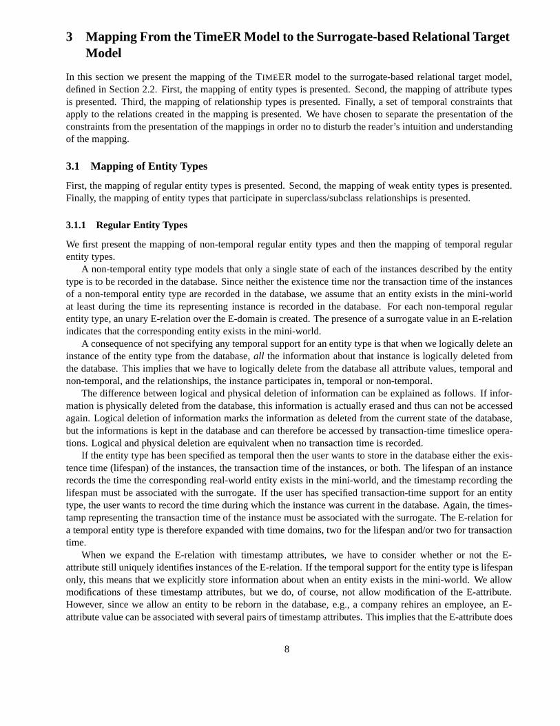
3 Mapping From the TimeER Model to the Surrogate-based Relational TargetModel
In this section we present the mapping of the TIMEER model to the surrogate-based relational target model,defined in Section 2.2. First, the mapping of entity types is presented. Second, the mapping of attribute typesis presented. Third, the mapping of relationship types is presented. Finally, a set of temporal constraints thatapply to the relations created in the mapping is presented. We have chosen to separate the presentation of theconstraints from the presentation of the mappings in order no to disturb the reader’s intuition and understandingof the mapping.
3.1 Mapping of Entity Types
First, the mapping of regular entity types is presented. Second, the mapping of weak entity types is presented.Finally, the mapping of entity types that participate in superclass/subclass relationships is presented.
3.1.1 Regular Entity Types
We first present the mapping of non-temporal regular entity types and then the mapping of temporal regularentity types.
A non-temporal entity type models that only a single state of each of the instances described by the entitytype is to be recorded in the database. Since neither the existence time nor the transaction time of the instancesof a non-temporal entity type are recorded in the database, we assume that an entity exists in the mini-worldat least during the time its representing instance is recorded in the database. For each non-temporal regularentity type, an unary E-relation over the E-domain is created. The presence of a surrogate value in an E-relationindicates that the corresponding entity exists in the mini-world.
A consequence of not specifying any temporal support for an entity type is that when we logically delete aninstance of the entity type from the database,all the information about that instance is logically deleted fromthe database. This implies that we have to logically delete from the database all attribute values, temporal andnon-temporal, and the relationships, the instance participates in, temporal or non-temporal.
The difference between logical and physical deletion of information can be explained as follows. If infor-mation is physically deleted from the database, this information is actually erased and thus can not be accessedagain. Logical deletion of information marks the information as deleted from the current state of the database,but the informations is kept in the database and can therefore be accessed by transaction-time timeslice opera-tions. Logical and physical deletion are equivalent when no transaction time is recorded.
If the entity type has been specified as temporal then the user wants to store in the database either the exis-tence time (lifespan) of the instances, the transaction time of the instances, or both. The lifespan of an instancerecords the time the corresponding real-world entity exists in the mini-world, and the timestamp recording thelifespan must be associated with the surrogate. If the user has specified transaction-time support for an entitytype, the user wants to record the time during which the instance was current in the database. Again, the times-tamp representing the transaction time of the instance must be associated with the surrogate. The E-relation fora temporal entity type is therefore expanded with time domains, two for the lifespan and/or two for transactiontime.
When we expand the E-relation with timestamp attributes, we have to consider whether or not the E-attribute still uniquely identifies instances of the E-relation. If the temporal support for the entity type is lifespanonly, this means that we explicitly store information about when an entity exists in the mini-world. We allowmodifications of these timestamp attributes, but we do, of course, not allow modification of the E-attribute.However, since we allow an entity to be reborn in the database, e.g., a company rehires an employee, an E-attribute value can be associated with several pairs of timestamp attributes. This implies that the E-attribute does
8
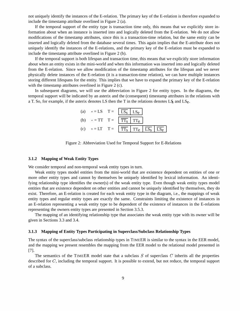
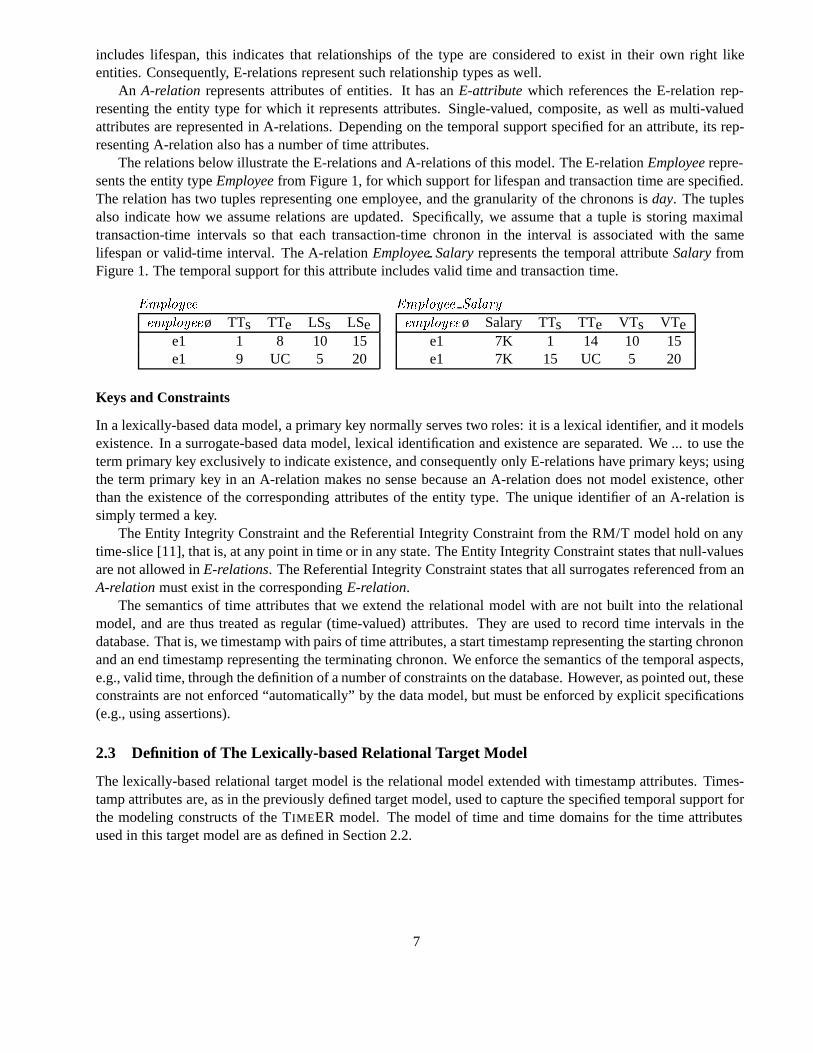
not uniquely identify the instances of the E-relation. The primary key of the E-relation is therefore expanded toinclude the timestamp attribute overlined in Figure 2 (a).
If the temporal support of the entity type is transaction time only, this means that we explicitly store in-formation about when an instance is inserted into and logically deleted from the E-relation. We do not allowmodifications of the timestamp attributes, since this is a transaction-time relation, but the same entity can beinserted and logically deleted from the database several times. This again implies that the E-attribute does notuniquely identify the instances of the E-relations, and the primary key of the E-relation must be expanded toinclude the timestamp attribute overlined in Figure 2 (b).
If the temporal support is both lifespan and transaction time, this means that we explicitly store informationabout when an entity exists in the mini-world and when this information was inserted into and logically deletedfrom the E-relation. Since we allow modification of the timestamp attributes for the lifespan and we neverphysically delete instances of the E-relation (it is a transaction-time relation), we can have multiple instancesstoring different lifespans for the entity. This implies that we have to expand the primary key of the E-relationwith the timestamp attributes overlined in Figure 2 (c).
In subsequent diagrams, we will use the abbreviation in Figure 2 for entity types. In the diagrams, thetemporal support will be indicated by an asterix and the (consequent) timestamp attributes in the relations witha T. So, for example, if the asterix denotes LS then the T in the relations denotes LSs and LSe.
(a) � = LS T = LSs LSe
(b) � = TT T = TTs TTe
(c) � = LT T = TTs TTe LSs LSe
Figure 2: Abbreviation Used for Temporal Support for E-Relations
3.1.2 Mapping of Weak Entity Types
We consider temporal and non-temporal weak entity types in turn.Weak entity types model entities from the mini-world that are existence dependent on entities of one or
more other entity types and cannot by themselves be uniquely identified by lexical information. An identi-fying relationship type identifies the owner(s) of the weak entity type. Even though weak entity types modelentities that are existence dependent on other entities and cannot be uniquely identified by themselves, they doexist. Therefore, an E-relation is created for each weak entity type in the diagram, i.e., the mappings of weakentity types and regular entity types are exactly the same. Constraints limiting the existence of instances inan E-relation representing a weak entity type to be dependent of the existence of instances in the E-relationsrepresenting the owners entity types are presented in Section 3.5.3.
The mapping of an identifying relationship type that associates the weak entity type with its owner will begiven in Sections 3.3 and 3.4.
3.1.3 Mapping of Entity Types Participating in Superclass/Subclass Relationship Types
The syntax of the superclass/subclass relationship types in TIMEER is similar to the syntax in the EER model,and the mapping we present resembles the mapping from the EER model to the relational model presented in[7].
The semantics of the TIMEER model state that a subclassS of superclassC inherits all the propertiesdescribed forC, including the temporal support. It is possible to extend, but not reduce, the temporal supportof a subclass.
9
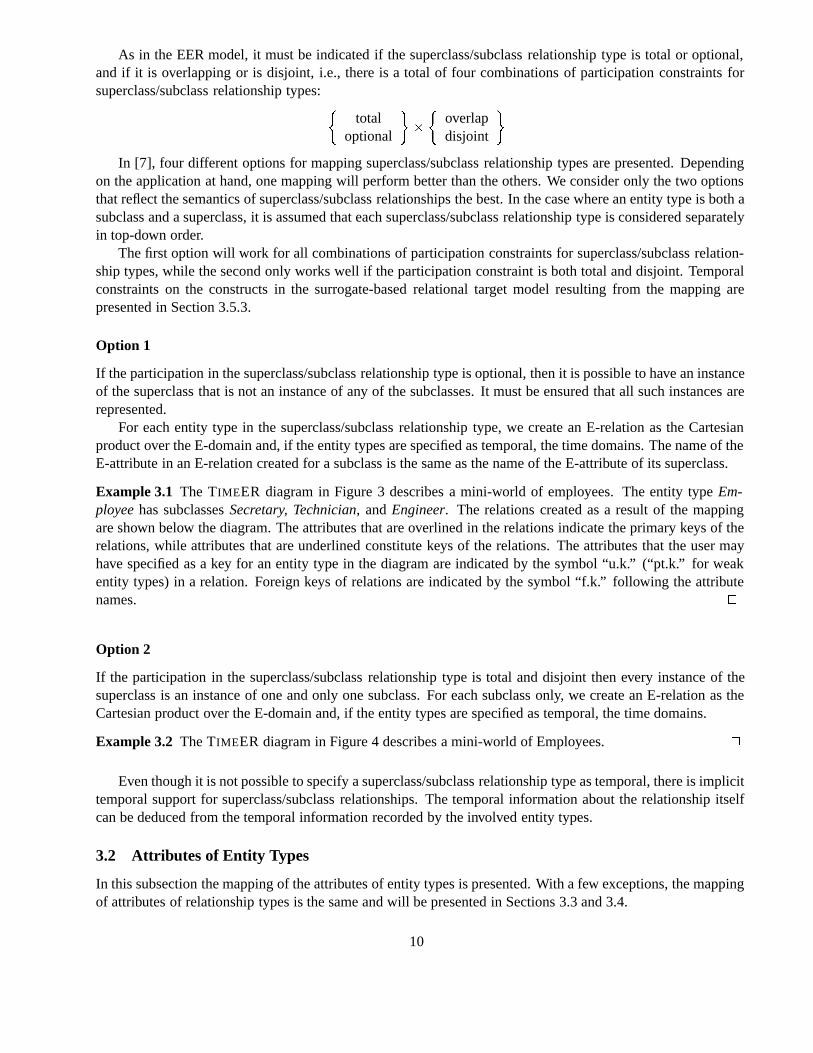
As in the EER model, it must be indicated if the superclass/subclass relationship type is total or optional,and if it is overlapping or is disjoint, i.e., there is a total of four combinations of participation constraints forsuperclass/subclass relationship types:�
totaloptional
��
�overlapdisjoint
�
In [7], four different options for mapping superclass/subclass relationship types are presented. Dependingon the application at hand, one mapping will perform better than the others. We consider only the two optionsthat reflect the semantics of superclass/subclass relationships the best. In the case where an entity type is both asubclass and a superclass, it is assumed that each superclass/subclass relationship type is considered separatelyin top-down order.
The first option will work for all combinations of participation constraints for superclass/subclass relation-ship types, while the second only works well if the participation constraint is both total and disjoint. Temporalconstraints on the constructs in the surrogate-based relational target model resulting from the mapping arepresented in Section 3.5.3.
Option 1
If the participation in the superclass/subclass relationship type is optional, then it is possible to have an instanceof the superclass that is not an instance of any of the subclasses. It must be ensured that all such instances arerepresented.
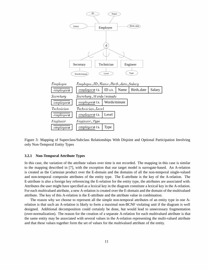
For each entity type in the superclass/subclass relationship type, we create an E-relation as the Cartesianproduct over the E-domain and, if the entity types are specified as temporal, the time domains. The name of theE-attribute in an E-relation created for a subclass is the same as the name of the E-attribute of its superclass.
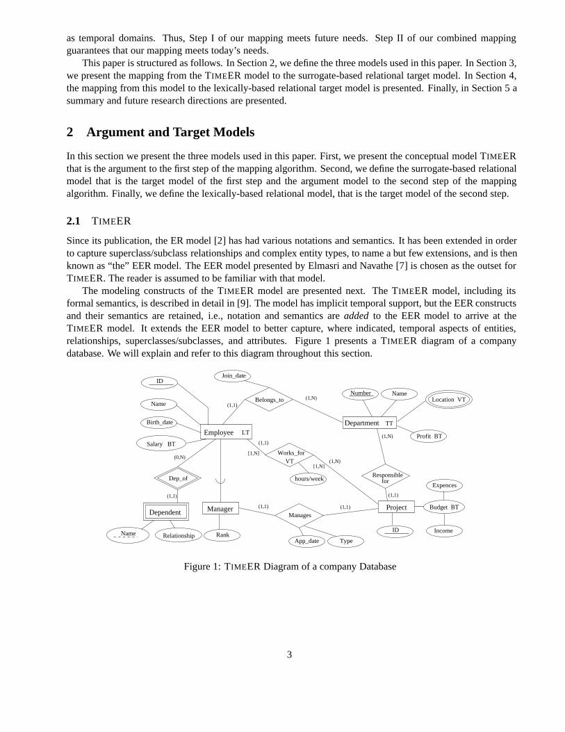
Example 3.1 The TIMEER diagram in Figure 3 describes a mini-world of employees. The entity typeEm-ployeehas subclassesSecretary, Technician, andEngineer. The relations created as a result of the mappingare shown below the diagram. The attributes that are overlined in the relations indicate the primary keys of therelations, while attributes that are underlined constitute keys of the relations. The attributes that the user mayhave specified as a key for an entity type in the diagram are indicated by the symbol “u.k.” (“pt.k.” for weakentity types) in a relation. Foreign keys of relations are indicated by the symbol “f.k.” following the attributenames. �
Option 2
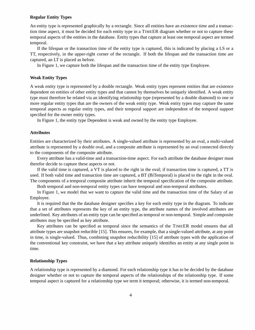
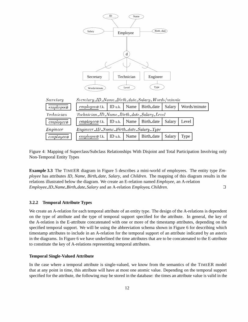
If the participation in the superclass/subclass relationship type is total and disjoint then every instance of thesuperclass is an instance of one and only one subclass. For each subclass only, we create an E-relation as theCartesian product over the E-domain and, if the entity types are specified as temporal, the time domains.
Example 3.2 The TIMEER diagram in Figure 4 describes a mini-world of Employees. �
Even though it is not possible to specify a superclass/subclass relationship type as temporal, there is implicittemporal support for superclass/subclass relationships. The temporal information about the relationship itselfcan be deduced from the temporal information recorded by the involved entity types.
3.2 Attributes of Entity Types
In this subsection the mapping of the attributes of entity types is presented. With a few exceptions, the mappingof attributes of relationship types is the same and will be presented in Sections 3.3 and 3.4.
10
Salary
ID Name
Birth_date
Level Type
Employee
Secretary Technician Engineer
d
Words/minute
Employee Employee ID Name Birth date Salary
employeeø employeeø f.k. ID u.k. Name Birth date Salary
Secretary Secretary Words�minute
employeeø employeeø f.k. Words/minute
Technician Technician Level
employeeø employeeø f.k. Level
Engineer Engineer Type
employeeø employeeø f.k. Type
Figure 3: Mapping of Superclass/Subclass Relationships With Disjoint and Optional Participation Involvingonly Non-Temporal Entity Types
3.2.1 Non-Temporal Attribute Types
In this case, the variation of the attribute values over time is not recorded. The mapping in this case is similarto the mapping described in [7], with the exception that our target model is surrogate-based. An A-relationis created as the Cartesian product over the E-domain and the domains of all the non-temporal single-valuedand non-temporal composite attributes of the entity type. The E-attribute is the key of the A-relation. TheE-attribute is also a foreign key referencing the E-relation for the entity type, the attributes are associated with.Attributes the user might have specified as a lexical key in the diagram constitute a lexical key in the A-relation.For each multivalued attribute, a new A-relation is created over the E-domain and the domain of the multivaluedattribute. The key of this A-relation is the E-attribute and the attribute value in combination.
The reason why we choose to represent all the simple non-temporal attributes of an entity type in one A-relation is that such an A-relation is likely to form a maximal non-BCNF violating unit if the diagram is welldesigned. Additional decomposition could certainly be done, but would lead to unnecessary fragmentation(over-normalization). The reason for the creation of a separate A-relation for each multivalued attribute is thatthe same entity may be associated with several values in the A-relation representing the multi-valued attributeand that these values together form the set of values for the multivalued attribute of the entity.
11
Salary Employee
Secretary Technician Engineer
d
ID Name
Birth_date
Level TypeWords/minute
Secretary Secretary ID Name Birth date Salary Words�minute
employeeø employeeø f.k. ID u.k. Name Birth date Salary Words/minute
Technician Technician ID Name Birth date Salary Level
employeeø employeeø f.k. ID u.k. Name Birth date Salary Level
Engineer Engineer ID Name Birth date Salary Type
employeeø employeeø f.k. ID u.k. Name Birth date Salary Type
Figure 4: Mapping of Superclass/Subclass Relationships With Disjoint and Total Participation Involving onlyNon-Temporal Entity Types
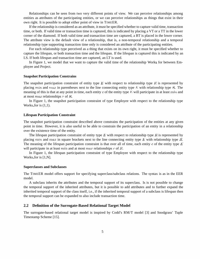
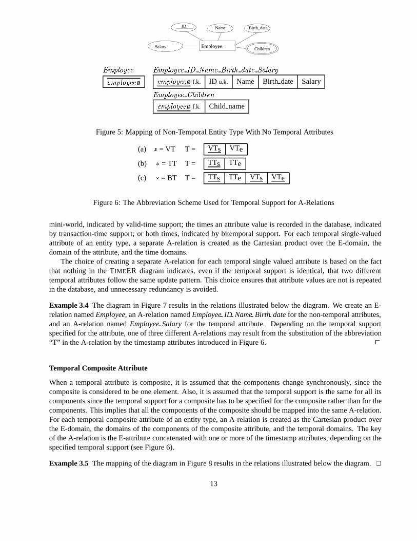
Example 3.3 The TIMEER diagram in Figure 5 describes a mini-world of employees. The entity typeEm-ployeehas attributesID, Name, Birthdate, Salary, andChildren. The mapping of this diagram results in therelations illustrated below the diagram. We create an E-relation namedEmployee, an A-relationEmployeeID NameBirth date Salaryand an A-relationEmployeeChildren. �
3.2.2 Temporal Attribute Types
We create an A-relation for each temporal attribute of an entity type. The design of the A-relations is dependenton the type of attribute and the type of temporal support specified for the attribute. In general, the key ofthe A-relation is the E-attribute concatenated with one or more of the timestamp attributes, depending on thespecified temporal support. We will be using the abbreviation schema shown in Figure 6 for describing whichtimestamp attributes to include in an A-relation for the temporal support of an attribute indicated by an asterixin the diagrams. In Figure 6 we have underlined the time attributes that are to be concatenated to the E-attributeto constitute the key of A-relations representing temporal attributes.
Temporal Single-Valued Attribute
In the case where a temporal attribute is single-valued, we know from the semantics of the TIMEER modelthat at any point in time, this attribute will have at most one atomic value. Depending on the temporal supportspecified for the attribute, the following may be stored in the database: the times an attribute value is valid in the
12
Employee
ID Name Birth_date
ChildrenSalary
Employee Employee ID Name Birth date Salary
employeeø employeeø f.k. ID u.k. Name Birth date Salary
Employee Children
employeeø f.k. Child name
Figure 5: Mapping of Non-Temporal Entity Type With No Temporal Attributes
(a) � = VT T = VTs VTe
(b) � = TT T = TTs TTe
(c) � = BT T = TTs TTe VTs VTe
Figure 6: The Abbreviation Scheme Used for Temporal Support for A-Relations
mini-world, indicated by valid-time support; the times an attribute value is recorded in the database, indicatedby transaction-time support; or both times, indicated by bitemporal support. For each temporal single-valuedattribute of an entity type, a separate A-relation is created as the Cartesian product over the E-domain, thedomain of the attribute, and the time domains.
The choice of creating a separate A-relation for each temporal single valued attribute is based on the factthat nothing in the TIMEER diagram indicates, even if the temporal support is identical, that two differenttemporal attributes follow the same update pattern. This choice ensures that attribute values are not is repeatedin the database, and unnecessary redundancy is avoided.
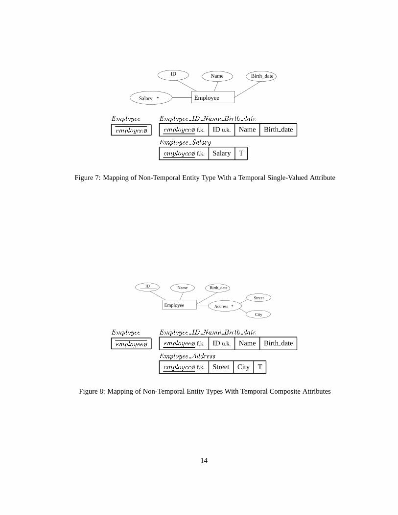
Example 3.4 The diagram in Figure 7 results in the relations illustrated below the diagram. We create an E-relation namedEmployee, an A-relation namedEmployeeID NameBirth datefor the non-temporal attributes,and an A-relation namedEmployeeSalary for the temporal attribute. Depending on the temporal supportspecified for the attribute, one of three different A-relations may result from the substitution of the abbreviation“T” in the A-relation by the timestamp attributes introduced in Figure 6. �
Temporal Composite Attribute
When a temporal attribute is composite, it is assumed that the components change synchronously, since thecomposite is considered to be one element. Also, it is assumed that the temporal support is the same for all itscomponents since the temporal support for a composite has to be specified for the composite rather than for thecomponents. This implies that all the components of the composite should be mapped into the same A-relation.For each temporal composite attribute of an entity type, an A-relation is created as the Cartesian product overthe E-domain, the domains of the components of the composite attribute, and the temporal domains. The keyof the A-relation is the E-attribute concatenated with one or more of the timestamp attributes, depending on thespecified temporal support (see Figure 6).
Example 3.5 The mapping of the diagram in Figure 8 results in the relations illustrated below the diagram.�
13
Employee
ID Name Birth_date
Salary *
Employee Employee ID Name Birth date
employeeø employeeø f.k. ID u.k. Name Birth date
Employee Salary
employeeø f.k. Salary T
Figure 7: Mapping of Non-Temporal Entity Type With a Temporal Single-Valued Attribute
Employee
ID Name Birth_date
City
Street
Address *
Employee Employee ID Name Birth date
employeeø employeeø f.k. ID u.k. Name Birth date
Employee Address
employeeø f.k. Street City T
Figure 8: Mapping of Non-Temporal Entity Types With Temporal Composite Attributes
14
Temporal Multivalued Attribute
If a temporal attribute is multivalued then its set of values changes over time, and this variation is recordedin the database. This implies that the changing set of values is timestamped in the database as the temporalmultivalued attribute changes its value.
For each temporal multivalued attribute of an entity type, a new A-relation is created as the Cartesianproduct over the E-domain, the domain of the attribute, and the appropriate time domains. The key of theA-relation is the concatenation of the E-attribute, the multivalued attribute, and one or more of the timestampattributes, depending on the specified temporal support. The constraints enforcing the complicated meaning ofthe above are presented in Section 3.5.1.
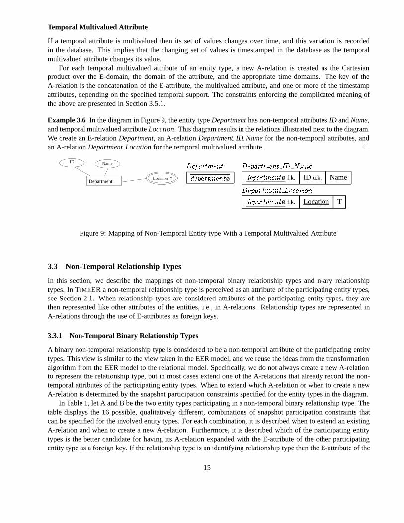
Example 3.6 In the diagram in Figure 9, the entity typeDepartmenthas non-temporal attributesID andName,and temporal multivalued attributeLocation. This diagram results in the relations illustrated next to the diagram.We create an E-relationDepartment, an A-relationDepartmentID Namefor the non-temporal attributes, andan A-relationDepartmentLocationfor the temporal multivalued attribute. �
ID Name
Location *Department
Department Department ID Name
departmentø departmentø f.k. ID u.k. Name
Department Location
departmentø f.k. Location T
Figure 9: Mapping of Non-Temporal Entity type With a Temporal Multivalued Attribute
3.3 Non-Temporal Relationship Types
In this section, we describe the mappings of non-temporal binary relationship types and n-ary relationshiptypes. In TIMEER a non-temporal relationship type is perceived as an attribute of the participating entity types,see Section 2.1. When relationship types are considered attributes of the participating entity types, they arethen represented like other attributes of the entities, i.e., in A-relations. Relationship types are represented inA-relations through the use of E-attributes as foreign keys.
3.3.1 Non-Temporal Binary Relationship Types
A binary non-temporal relationship type is considered to be a non-temporal attribute of the participating entitytypes. This view is similar to the view taken in the EER model, and we reuse the ideas from the transformationalgorithm from the EER model to the relational model. Specifically, we do not always create a new A-relationto represent the relationship type, but in most cases extend one of the A-relations that already record the non-temporal attributes of the participating entity types. When to extend which A-relation or when to create a newA-relation is determined by the snapshot participation constraints specified for the entity types in the diagram.
In Table 1, let A and B be the two entity types participating in a non-temporal binary relationship type. Thetable displays the 16 possible, qualitatively different, combinations of snapshot participation constraints thatcan be specified for the involved entity types. For each combination, it is described when to extend an existingA-relation and when to create a new A-relation. Furthermore, it is described which of the participating entitytypes is the better candidate for having its A-relation expanded with the E-attribute of the other participatingentity type as a foreign key. If the relationship type is an identifying relationship type then the E-attribute of the
15
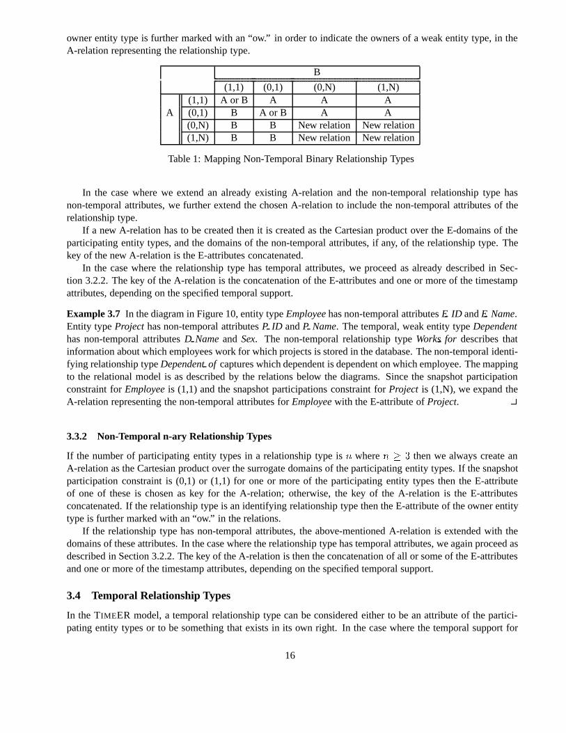
owner entity type is further marked with an “ow.” in order to indicate the owners of a weak entity type, in theA-relation representing the relationship type.
B
(1,1) (0,1) (0,N) (1,N)(1,1) A or B A A A
A (0,1) B A or B A A(0,N) B B New relation New relation(1,N) B B New relation New relation
Table 1: Mapping Non-Temporal Binary Relationship Types
In the case where we extend an already existing A-relation and the non-temporal relationship type hasnon-temporal attributes, we further extend the chosen A-relation to include the non-temporal attributes of therelationship type.
If a new A-relation has to be created then it is created as the Cartesian product over the E-domains of theparticipating entity types, and the domains of the non-temporal attributes, if any, of the relationship type. Thekey of the new A-relation is the E-attributes concatenated.
In the case where the relationship type has temporal attributes, we proceed as already described in Sec-tion 3.2.2. The key of the A-relation is the concatenation of the E-attributes and one or more of the timestampattributes, depending on the specified temporal support.
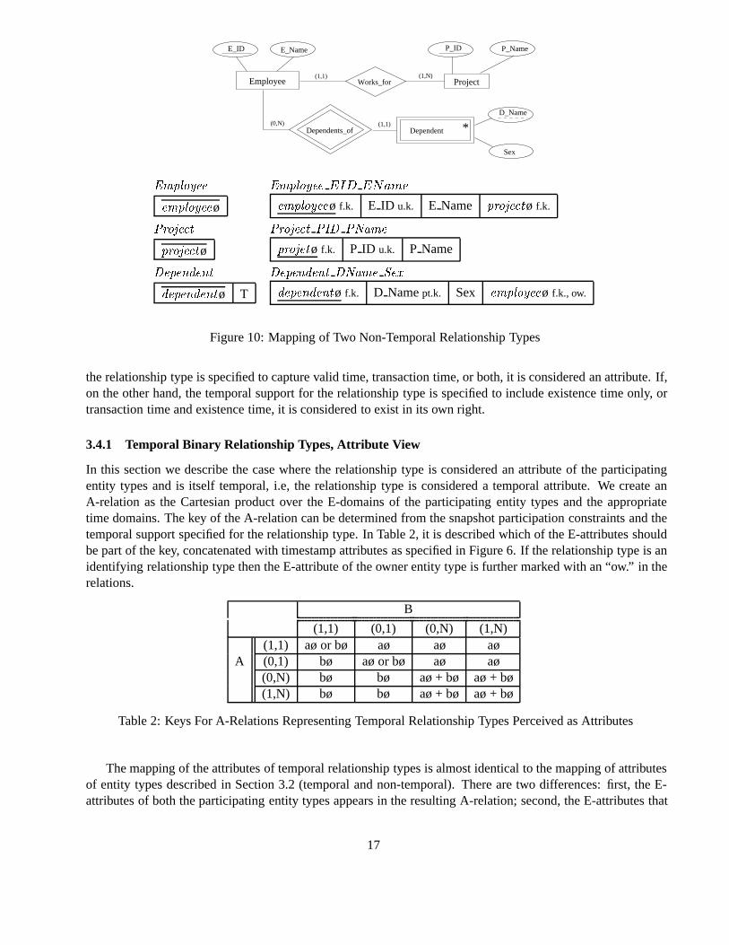
Example 3.7 In the diagram in Figure 10, entity typeEmployeehas non-temporal attributesE ID andE Name.Entity typeProjecthas non-temporal attributesP ID andP Name. The temporal, weak entity typeDependenthas non-temporal attributesD Nameand Sex. The non-temporal relationship typeWorksfor describes thatinformation about which employees work for which projects is stored in the database. The non-temporal identi-fying relationship typeDependentof captures which dependent is dependent on which employee. The mappingto the relational model is as described by the relations below the diagrams. Since the snapshot participationconstraint forEmployeeis (1,1) and the snapshot participations constraint forProject is (1,N), we expand theA-relation representing the non-temporal attributes forEmployeewith the E-attribute ofProject. �
3.3.2 Non-Temporal n-ary Relationship Types
If the number of participating entity types in a relationship type isn wheren � � then we always create anA-relation as the Cartesian product over the surrogate domains of the participating entity types. If the snapshotparticipation constraint is (0,1) or (1,1) for one or more of the participating entity types then the E-attributeof one of these is chosen as key for the A-relation; otherwise, the key of the A-relation is the E-attributesconcatenated. If the relationship type is an identifying relationship type then the E-attribute of the owner entitytype is further marked with an “ow.” in the relations.
If the relationship type has non-temporal attributes, the above-mentioned A-relation is extended with thedomains of these attributes. In the case where the relationship type has temporal attributes, we again proceed asdescribed in Section 3.2.2. The key of the A-relation is then the concatenation of all or some of the E-attributesand one or more of the timestamp attributes, depending on the specified temporal support.
3.4 Temporal Relationship Types
In the TIMEER model, a temporal relationship type can be considered either to be an attribute of the partici-pating entity types or to be something that exists in its own right. In the case where the temporal support for
16
ProjectWorks_forEmployee
E_ID E_Name P_ID P_Name
(1,1) (1,N)
Dependents_of
Sex
D_Name(0,N) (1,1)
Dependent *
Employee Employee EID EName
employeeø employeeø f.k. E ID u.k. E Name projectø f.k.
Project Project PID PName
projectø projetø f.k. P ID u.k. P Name
Dependent Dependent DName Sex
dependentø T dependentø f.k. D Namept.k. Sex employeeø f.k., ow.
Figure 10: Mapping of Two Non-Temporal Relationship Types
the relationship type is specified to capture valid time, transaction time, or both, it is considered an attribute. If,on the other hand, the temporal support for the relationship type is specified to include existence time only, ortransaction time and existence time, it is considered to exist in its own right.
3.4.1 Temporal Binary Relationship Types, Attribute View
In this section we describe the case where the relationship type is considered an attribute of the participatingentity types and is itself temporal, i.e, the relationship type is considered a temporal attribute. We create anA-relation as the Cartesian product over the E-domains of the participating entity types and the appropriatetime domains. The key of the A-relation can be determined from the snapshot participation constraints and thetemporal support specified for the relationship type. In Table 2, it is described which of the E-attributes shouldbe part of the key, concatenated with timestamp attributes as specified in Figure 6. If the relationship type is anidentifying relationship type then the E-attribute of the owner entity type is further marked with an “ow.” in therelations.
B
(1,1) (0,1) (0,N) (1,N)(1,1) aø or bø aø aø aø
A (0,1) bø aø or bø aø aø(0,N) bø bø aø + bø aø + bø(1,N) bø bø aø + bø aø + bø
Table 2: Keys For A-Relations Representing Temporal Relationship Types Perceived as Attributes
The mapping of the attributes of temporal relationship types is almost identical to the mapping of attributesof entity types described in Section 3.2 (temporal and non-temporal). There are two differences: first, the E-attributes of both the participating entity types appears in the resulting A-relation; second, the E-attributes that
17
is to be part of the keys is again determined by the snapshot participation constraint, and the temporal supportof the attribute is temporal, for the participating entity types, that is, the chose of E-attributes that should be partof the key is as described above.
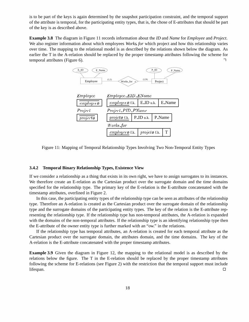
Example 3.8 The diagram in Figure 11 records information about theID andNamefor EmployeeandProject.We also register information about which employeesWorksfor which project and how this relationship variesover time. The mapping to the relational model is as described by the relations shown below the diagram. Asearlier the T in the A-relation should be replaced by the proper timestamp attributes following the scheme fortemporal attributes (Figure 6). �
ProjectEmployee
E_ID E_Name P_ID P_Name
(1,1) (1,N)Works_for *
Employee Employee EID EName
employeeø employeeø f.k. E ID u.k. E Name
Project Project PID PName
projectø projetø f.k. P ID u.k. P Name
Works for
employeeø f.k. projetø f.k. T
Figure 11: Mapping of Temporal Relationship Types Involving Two Non-Temporal Entity Types
3.4.2 Temporal Binary Relationship Types, Existence View
If we consider a relationship as a thing that exists in its own right, we have to assign surrogates to its instances.We therefore create an E-relation as the Cartesian product over the surrogate domain and the time domainsspecified for the relationship type. The primary key of the E-relation is the E-attribute concatenated with thetimestamp attributes, overlined in Figure 2.
In this case, the participating entity types of the relationship type can be seen as attributes of the relationshiptype. Therefore an A-relation is created as the Cartesian product over the surrogate domain of the relationshiptype and the surrogate domains of the participating entity types. The key of the relation is the E-attribute rep-resenting the relationship type. If the relationship type has non-temporal attributes, the A-relation is expandedwith the domains of the non-temporal attributes. If the relationship type is an identifying relationship type thenthe E-attribute of the owner entity type is further marked with an “ow.” in the relations.
If the relationship type has temporal attributes, an A-relation is created for each temporal attribute as theCartesian product over the surrogate domain, the attributes domain, and the time domains. The key of theA-relation is the E-attribute concatenated with the proper timestamp attributes.
Example 3.9 Given the diagram in Figure 12, the mapping to the relational model is as described by therelations below the figure. The T in the E-relation should be replaced by the proper timestamp attributesfollowing the scheme for E-relations (see Figure 2) with the restriction that the temporal support must includelifespan. �
18
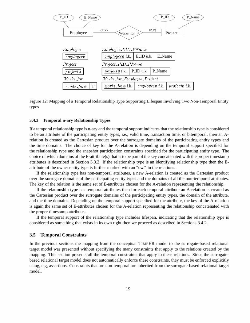
Project(X,Y) (Z,V)
Employee
E_ID E_Name P_ID P_Name
Works_for *
Employee Employee EID EName
employeeø employeeø f.k. E ID u.k. E Name
Project Project PID PName
projectø projectø f.k. P ID u.k. P Name
Works for Works for Employee Project
works forø T works forø f.k. employeeø f.k. projectø f.k.
Figure 12: Mapping of a Temporal Relationship Type Supporting Lifespan Involving Two Non-Temporal Entitytypes
3.4.3 Temporal n-ary Relationship Types
If a temporal relationship type is n-ary and the temporal support indicates that the relationship type is consideredto be an attribute of the participating entity types, i.e., valid time, transaction time, or bitemporal, then an A-relation is created as the Cartesian product over the surrogate domains of the participating entity types andthe time domains. The choice of key for the A-relation is depending on the temporal support specified forthe relationship type and the snapshot participation constraints specified for the participating entity type. Thechoice of which domains of the E-attribute(s) that is to be part of the key concatenated with the proper timestampattributes is described in Section 3.3.2. If the relationship type is an identifying relationship type then the E-attribute of the owner entity type is further marked with an “ow.” in the relations.
If the relationship type has non-temporal attributes, a new A-relation is created as the Cartesian productover the surrogate domains of the participating entity types and the domains of all the non-temporal attributes.The key of the relation is the same set of E-attributes chosen for the A-relation representing the relationship.
If the relationship type has temporal attributes then for each temporal attribute an A-relation is created asthe Cartesian product over the surrogate domains of the participating entity types, the domain of the attribute,and the time domains. Depending on the temporal support specified for the attribute, the key of the A-relationis again the same set of E-attributes chosen for the A-relation representing the relationship concatenated withthe proper timestamp attributes.
If the temporal support of the relationship type includes lifespan, indicating that the relationship type isconsidered as something that exists in its own right then we proceed as described in Sections 3.4.2.
3.5 Temporal Constraints
In the previous sections the mapping from the conceptual TIMEER model to the surrogate-based relationaltarget model was presented without specifying the many constraints that apply to the relations created by themapping. This section presents all the temporal constraints that apply to these relations. Since the surrogate-based relational target model does not automatically enforce these constraints, they must be enforced explicitlyusing, e.g, assertions. Constraints that are non-temporal are inherited from the surrogate-based relational targetmodel.
19
3.5.1 Within A-Relations
The following temporal constraints apply to A-relation recording temporal information. Constraints 3.1 – 3.3apply to A-relations representing simple attributes and to temporal relationship types perceived as attributes.They do not apply to A-relations representing temporal multivalued attributes. Constraints applying to thoseA-relations will be described later in this section.
It must be enforced that the information recorded by the A-relations is snapshot reducible [15], i.e., snap-shots of the database described using the temporal ER diagram constructs are the same as those described bythe corresponding snapshot ER diagram where all temporal constructs are replaced by their snapshot coun-terparts. As an example of snapshot reducibility, a temporal single-valued attribute is snapshot reducible to a(snapshot) single-valued attribute if the temporal single-valued attribute is single valued at each point in time.For A-relations recording valid time only, no two tuples of the A-relation containing the same E-attribute, orthe same set of E-attributes, can have overlapping valid-time intervals.
Constraint 3.1 (Snapshot Reducibility of Valid-Time A-Relations) LetK denote the set of E-attributes con-tained in A-relationR recording valid time only; then
�r�� r� � R�r��K � r��K � �r��V Ts� r��V Te� �r��V Ts� r��V Te� � �
This constraint is necessary to ensure that no valid-time timeslice on the A-relation will return more than onevalue for the attribute.
If the temporal information recorded is transaction time only then a snapshot reducibility constraint fortransaction time is enforced if the transaction-time start timestamp of a tuple in an A-relation is the time of theinsertion of the tuple into the database and the transaction-time end timestamp is the time of the logical deletionof the tuple from the database. Since, as time passes, the transaction time increases no two tuples in the relationwith the same value for the E-attribute, or the same set of E-attributes, have overlapping transactions-timeintervals.
Constraint 3.2 (Snapshot Reducibility of Transaction-Time A-Relations) LetK denote the set of E-attributescontained in A-relationR recording transaction time only; then
�r�� r� � R�r��K � r��K � �r��TTs� r��TTe� �r��TTs� r��TTe� � �
Bitemporal A-relations must also be snapshot reducible. This means that no two tuples associated withthe same E-attribute, or set of E-attributes, current at a given transactions-time point (the intersection of thetransaction-time intervals is non-empty) have overlapping valid-time intervals.
Constraint 3.3 (Snapshot Reducibility of Bitemporal A-Relations) LetK denote the set of E-attributes con-tained in A-relationR, recording both valid time and transaction time; then
�r�� r� � R��r��K � r��K � �r��TTs� r��TTe� �r��TTs� r��TTe� �� �
� �r��V Ts� r��V Te� �r��V Ts� r��V Te� � �
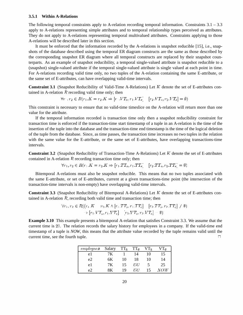
Example 3.10 This example presents a bitemporal A-relation that satisfies Constraint 3.3. We assume that thecurrent time is��. The relation records the salary history for employees in a company. If the valid-time endtimestamp of a tuple isNOW, this means that the attribute value recorded by the tuple remains valid until thecurrent time, see the fourth tuple. �
employeeø Salary TTs TTe VTs VTee1 7K 1 14 10 15e2 6K 10 18 10 14e1 7K 15 UC 5 25e2 8K 19 UC 15 NOW
20
Some A-relations represent temporal multivalued attributes of either entity types or relationship types. Asmentioned, the constraints defined above do not apply to these A-relations. The reason is that these record setvalued attributes and therefore sets of values changes over time. This implies that sets of values are timestampedin the database whenever a temporal multivalued attribute changes its value. We must therefore require, forthese A-relations, that the tuples that belong to the same value set record the same temporal information. Inorder to ensure this, we define aValue Setand redefine the constraints 3.1 through 3.3, replacing them withconstraints 3.4 through 3.6. These constraints apply to value sets in an A-relation instead of to individualtuples.
Definition 3.1 (Value Set) LetR be an A-relation representing a temporal multivalued attribute M. LetKdenote the set of E-attributes and letT be the set of timestamp attributes contained inR. Let r� andr� be twotuples inR. r� andr� belongs to the same value setS in R if and only if r� andr� have matching values of theE-attributes and the timestamp attributes.
r�� r� � R � r��K � r��K� � r��T � r��T r�� r� � S
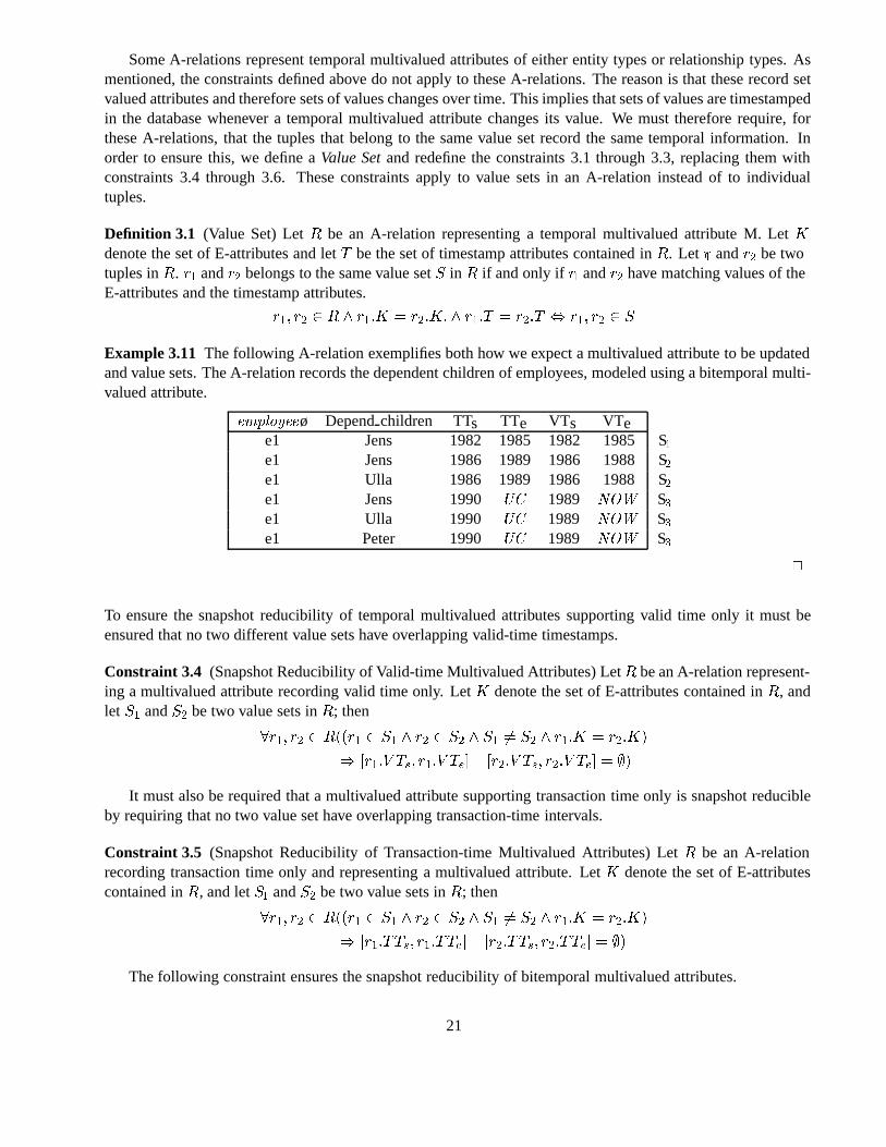
Example 3.11 The following A-relation exemplifies both how we expect a multivalued attribute to be updatedand value sets. The A-relation records the dependent children of employees, modeled using a bitemporal multi-valued attribute.
employeeø Dependchildren TTs TTe VTs VTee1 Jens 1982 1985 1982 1985S�e1 Jens 1986 1989 1986 1988S�e1 Ulla 1986 1989 1986 1988 S�e1 Jens 1990 UC 1989 NOW S�e1 Ulla 1990 UC 1989 NOW S�e1 Peter 1990 UC 1989 NOW S�
�
To ensure the snapshot reducibility of temporal multivalued attributes supporting valid time only it must beensured that no two different value sets have overlapping valid-time timestamps.
Constraint 3.4 (Snapshot Reducibility of Valid-time Multivalued Attributes) LetR be an A-relation represent-ing a multivalued attribute recording valid time only. LetK denote the set of E-attributes contained inR, andlet S� andS� be two value sets inR; then
�r�� r� � R��r� � S� � r� � S� � S� �� S� � r��K � r��K�
� �r��V Ts� r��V Te� �r��V Ts� r��V Te� � �
It must also be required that a multivalued attribute supporting transaction time only is snapshot reducibleby requiring that no two value set have overlapping transaction-time intervals.
Constraint 3.5 (Snapshot Reducibility of Transaction-time Multivalued Attributes) LetR be an A-relationrecording transaction time only and representing a multivalued attribute. LetK denote the set of E-attributescontained inR, and letS� andS� be two value sets inR; then
�r�� r� � R��r� � S� � r� � S� � S� �� S� � r��K � r��K�
� �r��TTs� r��TTe� �r��TTs� r��TTe� � �
The following constraint ensures the snapshot reducibility of bitemporal multivalued attributes.
21
Constraint 3.6 (Snapshot Reducibility of Bitemporal Multivalued Attributes) LetR be an A-relation record-ing valid time and transaction time representing a multivalued attribute. LetK denote the set of E-attributescontained inR, and letS� andS� be two value sets inR; then
�r�� r� � R��r� � S� � r� � S� � S� �� S� � r��K � r��K � �r��TTs� r��TTe� �r��TTs� r��TTe� �� �
� �r��V Ts� r��V Te� �r��V Ts� r��V Te� � ��
3.5.2 Between A-Relations and E-Relations
In this section we present the temporal constraints that must hold between A-relations representing either tem-poral attributes, temporal relationship types supporting valid time, transaction time, or both, and temporalattributes of these relationship types and the E-relations that represent the involved entity types.
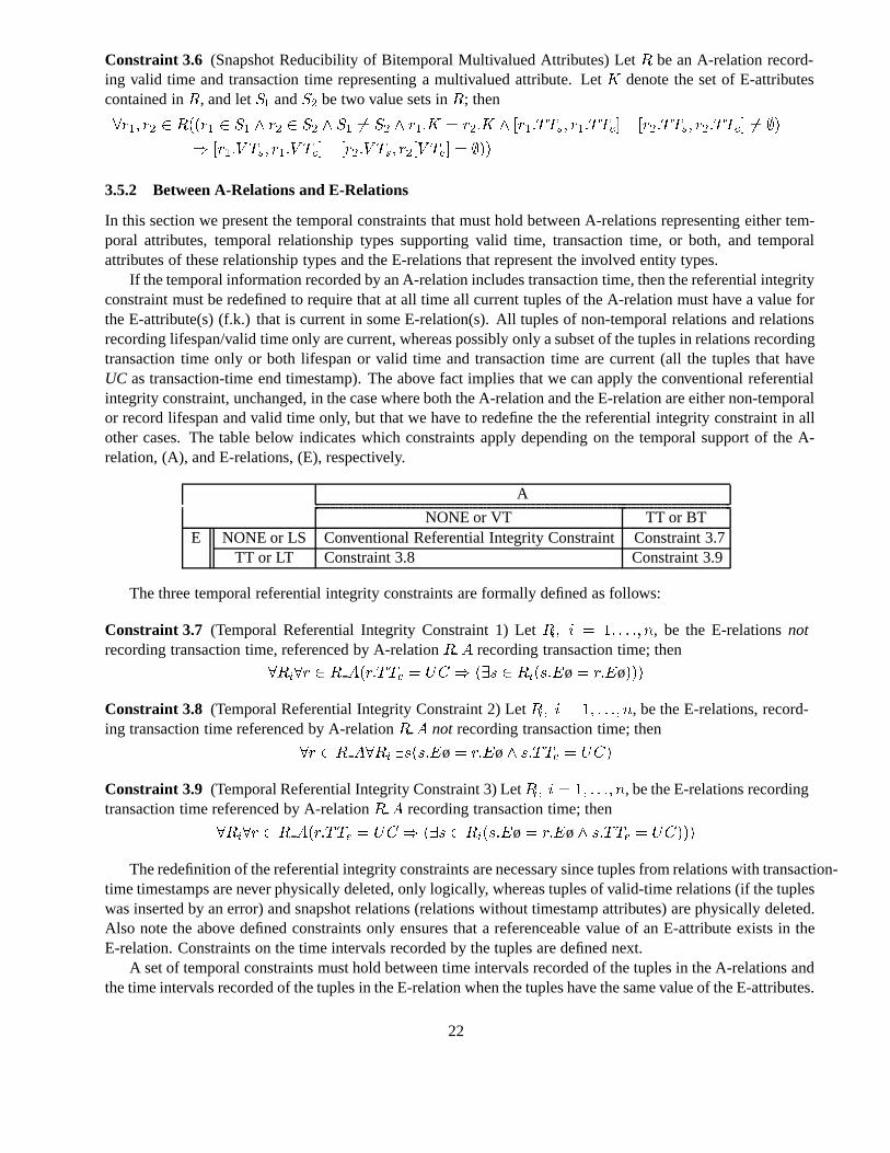
If the temporal information recorded by an A-relation includes transaction time, then the referential integrityconstraint must be redefined to require that at all time all current tuples of the A-relation must have a value forthe E-attribute(s) (f.k.) that is current in some E-relation(s). All tuples of non-temporal relations and relationsrecording lifespan/valid time only are current, whereas possibly only a subset of the tuples in relations recordingtransaction time only or both lifespan or valid time and transaction time are current (all the tuples that haveUC as transaction-time end timestamp). The above fact implies that we can apply the conventional referentialintegrity constraint, unchanged, in the case where both the A-relation and the E-relation are either non-temporalor record lifespan and valid time only, but that we have to redefine the the referential integrity constraint in allother cases. The table below indicates which constraints apply depending on the temporal support of the A-relation, (A), and E-relations, (E), respectively.
A
NONE or VT TT or BTE NONE or LS Conventional Referential Integrity ConstraintConstraint 3.7
TT or LT Constraint 3.8 Constraint 3.9
The three temporal referential integrity constraints are formally defined as follows:
Constraint 3.7 (Temporal Referential Integrity Constraint 1) LetRi� i � �� � � �� n, be the E-relationsnotrecording transaction time, referenced by A-relationR A recording transaction time; then
�Ri�r � R A�r�TTe � UC � ��s � Ri�s�Eø� r�Eø���
Constraint 3.8 (Temporal Referential Integrity Constraint 2) LetRi� i � �� � � �� n, be the E-relations, record-ing transaction time referenced by A-relationR A not recording transaction time; then
�r � R A�Ri �s�s�Eø� r�Eø� s�TTe � UC�
Constraint 3.9 (Temporal Referential Integrity Constraint 3) LetRi� i � �� � � �� n, be the E-relations recordingtransaction time referenced by A-relationR A recording transaction time; then
�Ri�r � R A�r�TTe � UC � ��s � Ri�s�Eø� r�Eø� s�TTe � UC���
The redefinition of the referential integrity constraints are necessary since tuples from relations with transaction-time timestamps are never physically deleted, only logically, whereas tuples of valid-time relations (if the tupleswas inserted by an error) and snapshot relations (relations without timestamp attributes) are physically deleted.Also note the above defined constraints only ensures that a referenceable value of an E-attribute exists in theE-relation. Constraints on the time intervals recorded by the tuples are defined next.
A set of temporal constraints must hold between time intervals recorded of the tuples in the A-relations andthe time intervals recorded of the tuples in the E-relation when the tuples have the same value of the E-attributes.
22
The purpose of the constraints is to ensure that attributes of, and relationships among, temporal entities cannotbe associated with time intervals for which the entities do not exist or are not registered in the database. Thereare 16 different combinations of temporal support to consider and the table below indicates which constraint, ifany, applies to a specific combination of temporal support between an A-relation (columns) and an E-relation(rows) referenced by the A-relation.
A
NONE VT TT BTNONE Observation 3.1 Observation 3.1 Observation 3.1 Observation 3.1
LS Observation 3.2 Constraint 3.10 Observation 3.3 Constraint 3.12,E Constraint 3.11 Observation 3.3
TT Observation 3.2 Observation 3.4 Constraint 3.13 Constraint 3.13Observation 3.4
LT Observation 3.2 Constraint 3.14 Constraint 3.15 Constraint 3.16
Observation 3.1 If the tuples in an E-relation does not record any temporal information, no temporal con-straints can be enforced on the temporal information, if any, recorded by the tuples in an A-relation referencingthe E-relation.
Observation 3.2 If the tuples in an A-relation does not record any temporal information, no temporal con-straints can be enforced on the temporal information, if any, recorded by the tuples in an E-relation referencedby the A-relation.
If the temporal support recorded by the tuples in an E-relation is lifespan only, and the temporal supportrecorded by the tuples in an A-relation referencing the E-relation is valid time only then the valid-time intervalrecorded by each tuple of the A-relation must be included in the lifespan interval recorded by the tuple in theE-relation with the same value of the E-attribute. This is expressed by the following constraint.
Constraint 3.10 (Valid Time Inclusion) LetR be an A-relation recording valid time only, letS be an E-relationreferenced byR recording lifespan only; then
�r � R �s � S�r�Eø � s�Eø� �s�LSs� s�LSe� � �r�V Ts� r�V Te��
The above constraint ensures that the tuples in an A-relations representing temporal attributes only recordvalid-time intervals that are included in the lifespan interval recorded by the tuple the E-relation with the samevalue of the E-attribute. It also ensures that the valid-time intervals recorded by the tuples in a A-relationrepresenting a relationship type recording valid time are included in the non-empty intersection of the lifespanintervals recorded by the participating temporal entities supporting lifespan only, since it must hold for eachE-relation referenced by the A-relation.
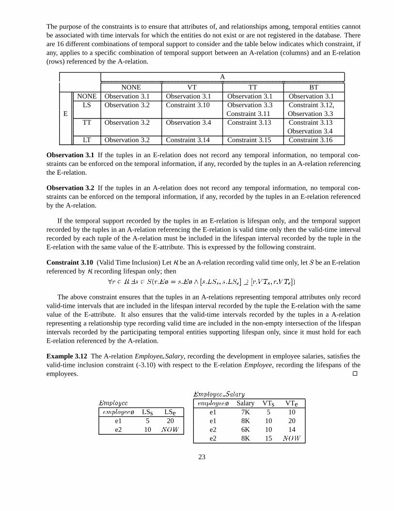
Example 3.12 The A-relationEmployeeSalary, recording the development in employee salaries, satisfies thevalid-time inclusion constraint (-3.10) with respect to the E-relationEmployee, recording the lifespans of theemployees. �
Employee
employeeø LSs LSee1 5 20e2 10 NOW
Employee Salary
employeeø Salary VTs VTee1 7K 5 10e1 8K 10 20e2 6K 10 14e2 8K 15 NOW
23
Observation 3.3 If the temporal information recorded by the tuples in an E-relation is lifespan only and thetemporal information recorded by the tuples in an A-relation referencing the E-relation is transaction time onlyit should not be enforced that the transaction-time intervals recorded by an tuple of the A-relation is includedin the lifespan interval recorded by the tuple in the E-relation with the same value of the E-attribute.
This should not be enforced because the user may have changed the lifespan interval of the tuple in theE-relation after the time, the first tuple representing an attribute value was inserted in the A-relation, or evenafter the current tuple in the A-relation, was inserted into the database. However, we have to require that allcurrent tuples in the A-relation reference tuples in the E-relation that are current, meaning that the current timeinstant (cnow) is included in the lifespan recorded by the tuple referenced. This is expressed by the followingconstraint.
Constraint 3.11 (Liveness Constraint) LetR be an A-relation recording transaction time only and letS be anE-relation referenced byR and recording lifespan only; then
�r � R�r�TTe � UC � ��s � S�r�Eø � s�Eø� cnow � �s�LSs� s�LSe����
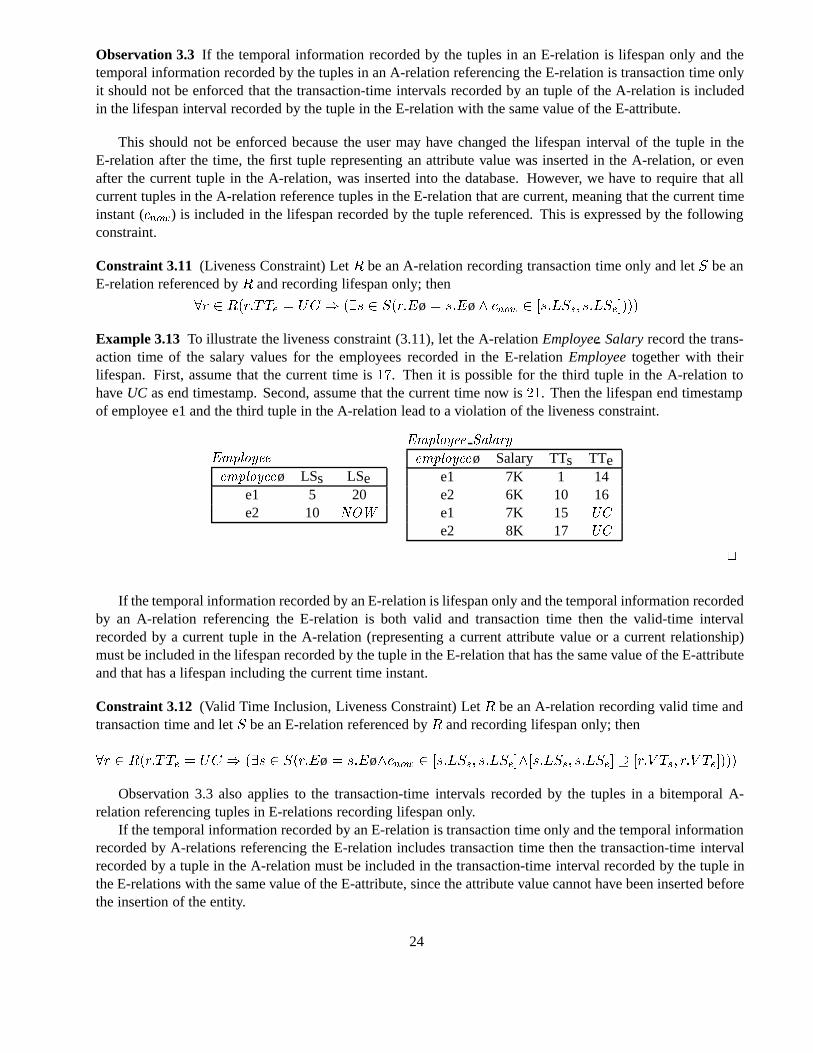
Example 3.13 To illustrate the liveness constraint (3.11), let the A-relationEmployeeSalaryrecord the trans-action time of the salary values for the employees recorded in the E-relationEmployeetogether with theirlifespan. First, assume that the current time is��. Then it is possible for the third tuple in the A-relation tohaveUC as end timestamp. Second, assume that the current time now is��. Then the lifespan end timestampof employee e1 and the third tuple in the A-relation lead to a violation of the liveness constraint.
Employee
employeeø LSs LSee1 5 20e2 10 NOW
Employee Salary
employeeø Salary TTs TTee1 7K 1 14e2 6K 10 16e1 7K 15 UC
e2 8K 17 UC
�
If the temporal information recorded by an E-relation is lifespan only and the temporal information recordedby an A-relation referencing the E-relation is both valid and transaction time then the valid-time intervalrecorded by a current tuple in the A-relation (representing a current attribute value or a current relationship)must be included in the lifespan recorded by the tuple in the E-relation that has the same value of the E-attributeand that has a lifespan including the current time instant.
Constraint 3.12 (Valid Time Inclusion, Liveness Constraint) LetR be an A-relation recording valid time andtransaction time and letS be an E-relation referenced byR and recording lifespan only; then
�r � R�r�TTe � UC � ��s � S�r�Eø � s�Eø�cnow � �s�LSs� s�LSe���s�LSs� s�LSe� � �r�V Ts� r�V Te����
Observation 3.3 also applies to the transaction-time intervals recorded by the tuples in a bitemporal A-relation referencing tuples in E-relations recording lifespan only.
If the temporal information recorded by an E-relation is transaction time only and the temporal informationrecorded by A-relations referencing the E-relation includes transaction time then the transaction-time intervalrecorded by a tuple in the A-relation must be included in the transaction-time interval recorded by the tuple inthe E-relations with the same value of the E-attribute, since the attribute value cannot have been inserted beforethe insertion of the entity.
24
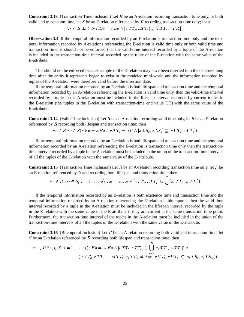
Constraint 3.13 (Transaction Time Inclusion) LetR be an A-relation recording transaction time only, or bothvalid and transaction time, letS be an E-relation referenced byR recording transaction time only; then
�r � R �s � S�r�Eø � s�Eø� �s�TTs� s�TTe� � �r�TTs� r�TTe��
Observation 3.4 If the temporal information recorded by an E-relation is transaction time only and the tem-poral information recorded by A-relations referencing the E-relation is valid time only or both valid time andtransaction time, it should not be enforced that the valid-time interval recorded by a tuple of the A-relationis included in the transaction-time interval recorded by the tuple of the E-relation with the same value of theE-attribute.
This should not be enforced because a tuple of the E-relation may have been inserted into the database longtime after the entity it represents began to exist in the modeled mini-world and the information recorded bytuples of the A-relation were therefore valid before the insertion date.
If the temporal information recorded by an E-relation is both lifespan and transaction time and the temporalinformation recorded by an A-relation referencing the E-relation is valid time only, then the valid-time intervalrecorded by a tuple in the A-relation must be included in the lifespan interval recorded by current tuples inthe E-relation (the tuples in the E-relation with transaction-time end value UC) with the same value of theE-attribute.
Constraint 3.14 (Valid Time Inclusion) LetR be an A-relation recording valid time only, letS be an E-relationreferenced byR recording both lifespan and transaction time; then
�r � R �s � S�r�Eø � s�Eø� s�TTe � UC � �s�LSs� s�LSe� � �r�V Ts� r�V Te��
If the temporal information recorded by an E-relation is both lifespan and transaction time and the temporalinformation recorded by an A-relation referencing the E-relation is transaction time only then the transaction-time interval recorded by a tuple in the A-relation must be included in the union of the transaction-time intervalsof all the tuples of the E-relation with the same value of the E-attribute.
Constraint 3.15 (Transaction Time Inclusion) LetR be an A-relation recording transaction time only, letS bean E-relation referenced byR and recording both lifespan and transaction time; then
�r � R �si � S� i � �� � � �� n�r�Eø � si�Eø� �r�TTs� r�TTe� �n�i��
�si�TTs� si�TTe��
If the temporal information recorded by an E-relation is both existence time and transaction time and thetemporal information recorded by an A-relation referencing the E-relation is bitemporal, then the valid-timeinterval recorded by a tuple in the A-relation must be included in the lifespan interval recorded by the tuplein the E-relation with the same value of the E-attribute if they are current at the same transaction time point.Furthermore, the transaction-time interval of the tuples in the A-relation must be included in the union of thetransaction-time intervals of all the tuples of the E-relation with the same value of the E-attribute.
Constraint 3.16 (Bitemporal Inclusion) LetR be an A-relation recording both valid and transaction time, letS be an E-relation referenced byR recording both lifespan and transaction time; then
�r � R �si � S� i � �� � � �� n��r�Eø � si�Eø� �r�TTs� r�TTe� �n�i��
�si�TTs� si�TTe�� �
��r�TTs� r�TTe� �si�TTs� si�TTe� �� � �r�V Ts� r�V Te� � �si�LSs� si�LSe���
25
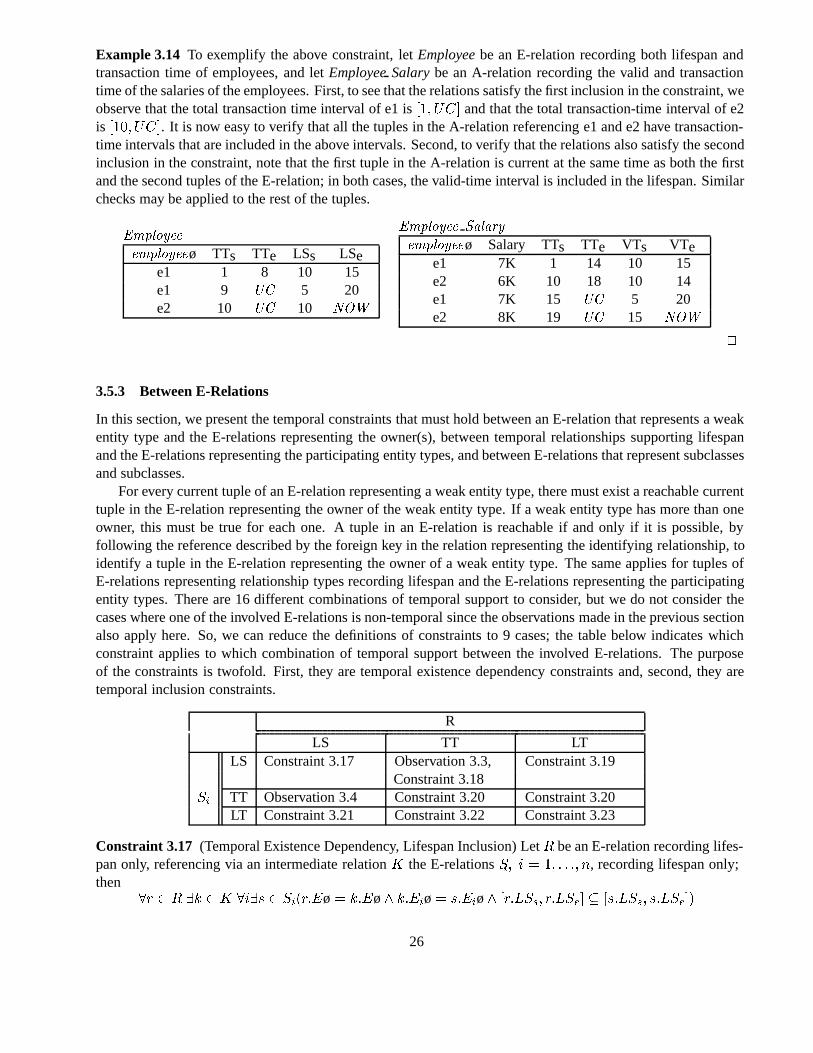
Example 3.14 To exemplify the above constraint, letEmployeebe an E-relation recording both lifespan andtransaction time of employees, and letEmployeeSalarybe an A-relation recording the valid and transactiontime of the salaries of the employees. First, to see that the relations satisfy the first inclusion in the constraint, weobserve that the total transaction time interval of e1 is��� UC� and that the total transaction-time interval of e2is ��� UC�. It is now easy to verify that all the tuples in the A-relation referencing e1 and e2 have transaction-time intervals that are included in the above intervals. Second, to verify that the relations also satisfy the secondinclusion in the constraint, note that the first tuple in the A-relation is current at the same time as both the firstand the second tuples of the E-relation; in both cases, the valid-time interval is included in the lifespan. Similarchecks may be applied to the rest of the tuples.
Employee
employeeø TTs TTe LSs LSee1 1 8 10 15e1 9 UC 5 20e2 10 UC 10 NOW
Employee Salary
employeeø Salary TTs TTe VTs VTee1 7K 1 14 10 15e2 6K 10 18 10 14e1 7K 15 UC 5 20e2 8K 19 UC 15 NOW
�
3.5.3 Between E-Relations
In this section, we present the temporal constraints that must hold between an E-relation that represents a weakentity type and the E-relations representing the owner(s), between temporal relationships supporting lifespanand the E-relations representing the participating entity types, and between E-relations that represent subclassesand subclasses.
For every current tuple of an E-relation representing a weak entity type, there must exist a reachable currenttuple in the E-relation representing the owner of the weak entity type. If a weak entity type has more than oneowner, this must be true for each one. A tuple in an E-relation is reachable if and only if it is possible, byfollowing the reference described by the foreign key in the relation representing the identifying relationship, toidentify a tuple in the E-relation representing the owner of a weak entity type. The same applies for tuples ofE-relations representing relationship types recording lifespan and the E-relations representing the participatingentity types. There are 16 different combinations of temporal support to consider, but we do not consider thecases where one of the involved E-relations is non-temporal since the observations made in the previous sectionalso apply here. So, we can reduce the definitions of constraints to 9 cases; the table below indicates whichconstraint applies to which combination of temporal support between the involved E-relations. The purposeof the constraints is twofold. First, they are temporal existence dependency constraints and, second, they aretemporal inclusion constraints.
R
LS TT LTLS Constraint 3.17 Observation 3.3, Constraint 3.19
Constraint 3.18Si TT Observation 3.4 Constraint 3.20 Constraint 3.20
LT Constraint 3.21 Constraint 3.22 Constraint 3.23
Constraint 3.17 (Temporal Existence Dependency, Lifespan Inclusion) LetR be an E-relation recording lifes-pan only, referencing via an intermediate relationK the E-relationsSi� i � �� � � �� n, recording lifespan only;then
�r � R �k � K �i�s � Si�r�Eø � k�Eø� k�Eiø� s�Eiø� �r�LSs� r�LSe� � �s�LSs� s�LSe��
26
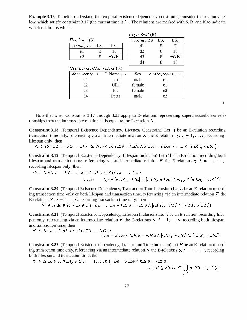
Example 3.15 To better understand the temporal existence dependency constraints, consider the relations be-low, which satisfy constraint 3.17 (the current time is��. The relations are marked with S, R, and K to indicatewhich relation is which.
Employee (S)employeeø LSs LSe
e1 3 10e2 5 NOW
Dependent (R)dependentø LSs LSe
d1 5 7d2 6 10d3 8 NOW
d4 8 15Dependent DName Sex (K)dependentø f.k. D Namept.k. Sex employeeø f.k., ow.
d1 Jens male e1d2 Ulla female e1d3 Pia female e2d4 Peter male e2
�
Note that when Constraints 3.17 through 3.23 apply to E-relations representing superclass/subclass rela-tionships then the intermediate relationK is equal to the E-relationR.
Constraint 3.18 (Temporal Existence Dependency, Liveness Constraint) LetR be an E-relation recordingtransaction time only, referencing via an intermediate relationK the E-relationsSi� i � �� � � �� n, recordinglifespan only; then�r � R�r�TTe � UC � �k � K �i�s � Si�r�Eø � k�Eø� k�Eiø� s�Eiø� cnow � �s�LSs� s�LSe���
Constraint 3.19 (Temporal Existence Dependency, Lifespan Inclusion) LetR be an E-relation recording bothlifespan and transaction time, referencing via an intermediate relationK the E-relationsSi� i � �� � � �� n,recording lifespan only; then
�r � R�r�TTe � UC � �k � K �i�s � Si�r�Eø � k�Eø�
k�Eiø� s�Eiø� �r�LSs� r�LSe� � �s�LSs� s�LSe� � cnow � �s�LSs� s�LSe���
Constraint 3.20 (Temporal Existence Dependency, Transaction Time Inclusion) LetR be an E-relation record-ing transaction time only or both lifespan and transaction time, referencing via an intermediate relationK theE-relationsSi� i � �� � � �� n, recording transaction time only; then
�r � R �k � K �i�s � Si�r�Eø � k�Eø� k�Eiø� s�Eiø� �r�TTs� r�TTe� � �s�TTs� s�TTe��
Constraint 3.21 (Temporal Existence Dependency, Lifespan Inclusion) LetR be an E-relation recording lifes-pan only, referencing via an intermediate relationK the E-relationsSi� i � �� � � �� n, recording both lifespanand transaction time; then�r � R �k � K �i�s � Si�s�TTe � UC �
r�Eø� k�Eø� k�Eiø� s�Eiø� �r�LSs� r�LSe� � �s�LSs� s�LSe��
Constraint 3.22 (Temporal Existence dependency, Transaction Time Inclusion) LetR be an E-relation record-ing transaction time only, referencing via an intermediate relationK the E-relationsSi� i � �� � � �� n, recordingboth lifespan and transaction time; then�r � R �k � K �i�sj � Si� j � �� � � ��m�r�Eø � k�Eø� k�Eiø� s�Eiø
� �r�TTs� r�TTe� �m�j��
�sj�TTs� sj�TTe��
27
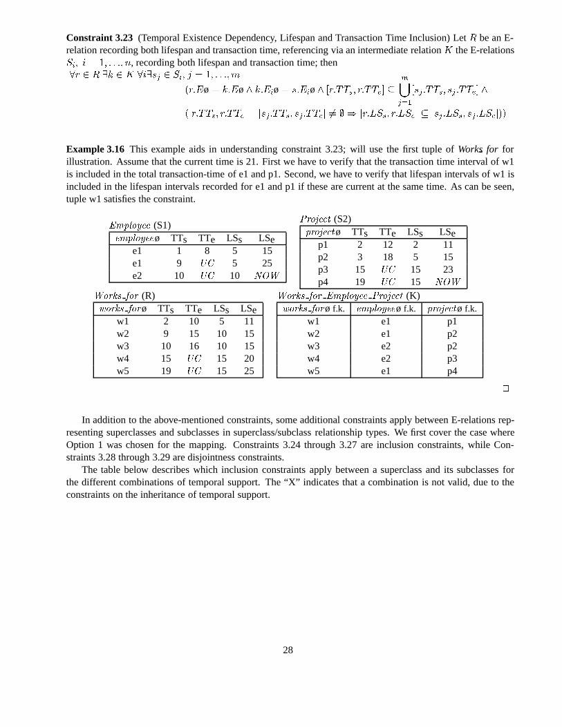
Constraint 3.23 (Temporal Existence Dependency, Lifespan and Transaction Time Inclusion) LetR be an E-relation recording both lifespan and transaction time, referencing via an intermediate relationK the E-relationsSi� i � �� � � �� n, recording both lifespan and transaction time; then�r � R �k � K �i�sj � Si� j � �� � � ��m
�r�Eø � k�Eø� k�Eiø� s�Eiø� �r�TTs� r�TTe� �m�j��
�sj �TTs� sj �TTe� �
��r�TTs� r�TTe� �sj �TTs� sj�TTe� �� � �r�LSs� r�LSe� � �sj�LSs� sj �LSe���
Example 3.16 This example aids in understanding constraint 3.23; will use the first tuple ofWorksfor forillustration. Assume that the current time is 21. First we have to verify that the transaction time interval of w1is included in the total transaction-time of e1 and p1. Second, we have to verify that lifespan intervals of w1 isincluded in the lifespan intervals recorded for e1 and p1 if these are current at the same time. As can be seen,tuple w1 satisfies the constraint.
Employee (S1)employeeø TTs TTe LSs LSe
e1 1 8 5 15e1 9 UC 5 25e2 10 UC 10 NOW
Project (S2)projectø TTs TTe LSs LSe
p1 2 12 2 11p2 3 18 5 15p3 15 UC 15 23p4 19 UC 15 NOW
Works for (R)works forø TTs TTe LSs LSe
w1 2 10 5 11w2 9 15 10 15w3 10 16 10 15w4 15 UC 15 20w5 19 UC 15 25
Works for Employee Project (K)works forø f.k. employeeø f.k. projectø f.k.
w1 e1 p1w2 e1 p2w3 e2 p2w4 e2 p3w5 e1 p4
�
In addition to the above-mentioned constraints, some additional constraints apply between E-relations rep-resenting superclasses and subclasses in superclass/subclass relationship types. We first cover the case whereOption 1 was chosen for the mapping. Constraints 3.24 through 3.27 are inclusion constraints, while Con-straints 3.28 through 3.29 are disjointness constraints.
The table below describes which inclusion constraints apply between a superclass and its subclasses forthe different combinations of temporal support. The “X” indicates that a combination is not valid, due to theconstraints on the inheritance of temporal support.
28
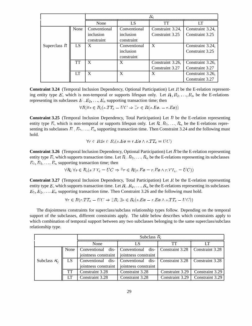
Ri
None LS TT LTNone Conventional
inclusionconstraint
Conventionalinclusionconstraint
Constraint 3.24,Constraint 3.25
Constraint 3.24,Constraint 3.25
SuperclassR LS X Conventionalinclusionconstraint
X Constraint 3.24,Constraint 3.25
TT X X Constraint 3.26,Constraint 3.27
Constraint 3.26,Constraint 3.27
LT X X X Constraint 3.26,Constraint 3.27
Constraint 3.24 (Temporal Inclusion Dependency, Optional Participation) LetR be the E-relation represent-ing entity typeE, which is non-temporal or supports lifespan only. LetR�� R�� � � �� Rn be the E-relationsrepresenting its subclassesE�� E�� � � �� En supporting transaction time; then
�Ri�s � Ri�s�TTe � UC � �r � R�s�Eø� � r�Eø��
Constraint 3.25 (Temporal Inclusion Dependency, Total Participation) LetR be the E-relation representingentity typeE, which is non-temporal or supports lifespan only. LetR�� R�� � � �� Rn be the E-relations repre-senting its subclassesE�� E�� � � �� En supporting transaction time. Then Constraint 3.24 and the following musthold.
�r � R�s � Ri�s�Eø� r�Eø� s�TTe � UC�
Constraint 3.26 (Temporal Inclusion Dependency, Optional Participation) LetR be the E-relation representingentity typeE, which supports transaction time. LetR�� R�� � � �� Rn be the E-relations representing its subclassesE�� E�� � � �� En supporting transaction time; then
�Ri �s � Ri�s�TTe � UC � �r � R�s�Eø� r�Eø� r�TTe� � UC��
Constraint 3.27 (Temporal Inclusion Dependency, Total Participation) LetR be the E-relation representingentity typeE, which supports transaction time. LetR�� R�� � � �� Rn be the E-relations representing its subclassesE�� E�� � � �� En supporting transaction time. Then Constraint 3.26 and the following must hold.
�r � R�r�TTe � UC � �Ri �s � Ri�s�Eø� r�Eø� s�TTe � UC��
The disjointness constraints for superclass/subclass relationship types follow. Depending on the temporalsupport of the subclasses, different constraints apply. The table below describes which constraints apply towhich combination of temporal support between any two subclasses belonging to the same superclass/subclassrelationship type.
SubclassRi
None LS TT LTNone Conventional dis-
jointness constraintConventional dis-jointness constraint
Constraint 3.28 Constraint 3.28
SubclassRj LS Conventional dis-jointness constraint
Conventional dis-jointness constraint
Constraint 3.28 Constraint 3.28
TT Constraint 3.28 Constraint 3.28 Constraint 3.29 Constraint 3.29LT Constraint 3.28 Constraint 3.28 Constraint 3.29 Constraint 3.29
29
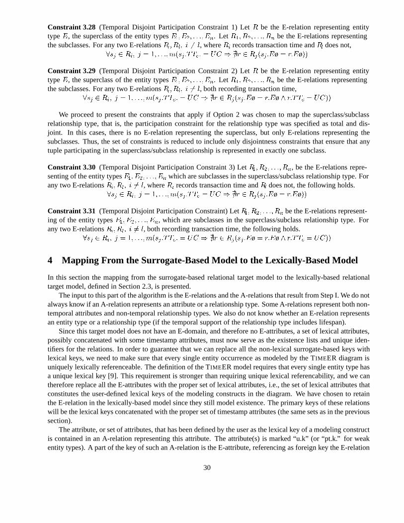
Constraint 3.28 (Temporal Disjoint Participation Constraint 1) LetR be the E-relation representing entitytypeE, the superclass of the entity typesE�� E�� � � �� En. LetR�� R�� � � �� Rn be the E-relations representingthe subclasses. For any two E-relationsRi� Rl� i �� l, whereRi records transaction time andRl does not,
�sj � Ri� j � �� � � ��m�sj �TTe� � UC � �r � Rj�sj�Eø � r�Eø��
Constraint 3.29 (Temporal Disjoint Participation Constraint 2) LetR be the E-relation representing entitytypeE, the superclass of the entity typesE�� E�� � � �� En. LetR�� R�� � � �� Rn be the E-relations representingthe subclasses. For any two E-relationsRi� Rl� i �� l, both recording transaction time,
�sj � Ri� j � �� � � ��m�sj �TTe� � UC � �r � Rj�sj �Eø� r�Eø� r�TTe � UC��
We proceed to present the constraints that apply if Option 2 was chosen to map the superclass/subclassrelationship type, that is, the participation constraint for the relationship type was specified as total and dis-joint. In this cases, there is no E-relation representing the superclass, but only E-relations representing thesubclasses. Thus, the set of constraints is reduced to include only disjointness constraints that ensure that anytuple participating in the superclass/subclass relationship is represented in exactly one subclass.
Constraint 3.30 (Temporal Disjoint Participation Constraint 3) LetR�� R�� � � �� Rn, be the E-relations repre-senting of the entity typesE�� E�� � � �� En which are subclasses in the superclass/subclass relationship type. Forany two E-relationsRi� Rl� i �� l, whereRi records transaction time andRl does not, the following holds.
�sj � Ri� j � �� � � ��m�sj�TTe � UC � �r � Rj�sj �Eø� r�Eø��
Constraint 3.31 (Temporal Disjoint Participation Constraint) LetR�� R�� � � �� Rn be the E-relations represent-ing of the entity typesE�� E�� � � �� En, which are subclasses in the superclass/subclass relationship type. Forany two E-relationsRi� Rl� i �� l, both recording transaction time, the following holds.
�sj � Ri� j � �� � � ��m�sj �TTe� � UC � �r � Rj�sj �Eø� r�Eø� r�TTe � UC��
4 Mapping From the Surrogate-Based Model to the Lexically-Based Model
In this section the mapping from the surrogate-based relational target model to the lexically-based relationaltarget model, defined in Section 2.3, is presented.
The input to this part of the algorithm is the E-relations and the A-relations that result from Step I. We do notalways know if an A-relation represents an attribute or a relationship type. Some A-relations represent both non-temporal attributes and non-temporal relationship types. We also do not know whether an E-relation representsan entity type or a relationship type (if the temporal support of the relationship type includes lifespan).
Since this target model does not have an E-domain, and therefore no E-attributes, a set of lexical attributes,possibly concatenated with some timestamp attributes, must now serve as the existence lists and unique iden-tifiers for the relations. In order to guarantee that we can replace all the non-lexical surrogate-based keys withlexical keys, we need to make sure that every single entity occurrence as modeled by the TIMEER diagram isuniquely lexically referenceable. The definition of the TIMEER model requires that every single entity type hasa unique lexical key [9]. This requirement is stronger than requiring unique lexical referencability, and we cantherefore replace all the E-attributes with the proper set of lexical attributes, i.e., the set of lexical attributes thatconstitutes the user-defined lexical keys of the modeling constructs in the diagram. We have chosen to retainthe E-relation in the lexically-based model since they still model existence. The primary keys of these relationswill be the lexical keys concatenated with the proper set of timestamp attributes (the same sets as in the previoussection).
The attribute, or set of attributes, that has been defined by the user as the lexical key of a modeling constructis contained in an A-relation representing this attribute. The attribute(s) is marked “u.k” (or “pt.k.” for weakentity types). A part of the key of such an A-relation is the E-attribute, referencing as foreign key the E-relation
30
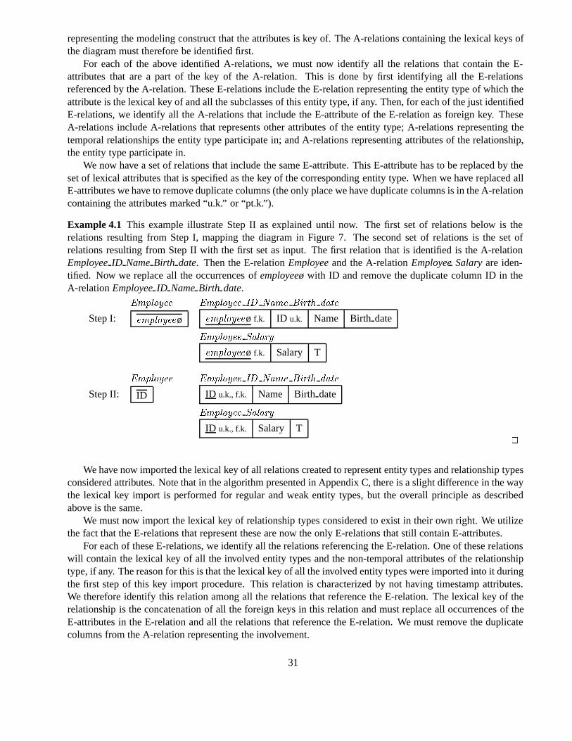
representing the modeling construct that the attributes is key of. The A-relations containing the lexical keys ofthe diagram must therefore be identified first.
For each of the above identified A-relations, we must now identify all the relations that contain the E-attributes that are a part of the key of the A-relation. This is done by first identifying all the E-relationsreferenced by the A-relation. These E-relations include the E-relation representing the entity type of which theattribute is the lexical key of and all the subclasses of this entity type, if any. Then, for each of the just identifiedE-relations, we identify all the A-relations that include the E-attribute of the E-relation as foreign key. TheseA-relations include A-relations that represents other attributes of the entity type; A-relations representing thetemporal relationships the entity type participate in; and A-relations representing attributes of the relationship,the entity type participate in.
We now have a set of relations that include the same E-attribute. This E-attribute has to be replaced by theset of lexical attributes that is specified as the key of the corresponding entity type. When we have replaced allE-attributes we have to remove duplicate columns (the only place we have duplicate columns is in the A-relationcontaining the attributes marked “u.k.” or “pt.k.”).
Example 4.1 This example illustrate Step II as explained until now. The first set of relations below is therelations resulting from Step I, mapping the diagram in Figure 7. The second set of relations is the set ofrelations resulting from Step II with the first set as input. The first relation that is identified is the A-relationEmployeeID NameBirth date. Then the E-relationEmployeeand the A-relationEmployeeSalaryare iden-tified. Now we replace all the occurrences ofemployeeøwith ID and remove the duplicate column ID in theA-relationEmployeeID NameBirth date.
Employee Employee ID Name Birth date
Step I: employeeø employeeø f.k. ID u.k. Name Birth date
Employee Salary
employeeø f.k. Salary T
Employee Employee ID Name Birth date
Step II: ID ID u.k., f.k. Name Birth date
Employee Salary
ID u.k., f.k. Salary T�
We have now imported the lexical key of all relations created to represent entity types and relationship typesconsidered attributes. Note that in the algorithm presented in Appendix C, there is a slight difference in the waythe lexical key import is performed for regular and weak entity types, but the overall principle as describedabove is the same.
We must now import the lexical key of relationship types considered to exist in their own right. We utilizethe fact that the E-relations that represent these are now the only E-relations that still contain E-attributes.
For each of these E-relations, we identify all the relations referencing the E-relation. One of these relationswill contain the lexical key of all the involved entity types and the non-temporal attributes of the relationshiptype, if any. The reason for this is that the lexical key of all the involved entity types were imported into it duringthe first step of this key import procedure. This relation is characterized by not having timestamp attributes.We therefore identify this relation among all the relations that reference the E-relation. The lexical key of therelationship is the concatenation of all the foreign keys in this relation and must replace all occurrences of theE-attributes in the E-relation and all the relations that reference the E-relation. We must remove the duplicatecolumns from the A-relation representing the involvement.
31
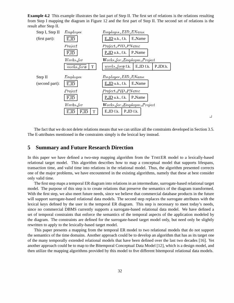
Example 4.2 This example illustrates the last part of Step II. The first set of relations is the relations resultingfrom Step I mapping the diagram in Figure 12 and the first part of Step II. The second set of relations is theresult after Step II.
Step I, Step II Employee Employee EID EName
(first part): E ID E ID u.k., f.k. E Name
Project Project PID PName
P ID P ID u.k., f.k. P Name
Works for Works for Employee Project
works forø T works forø f.k. E ID f.k. P IDf.k.
Step II Employee Employee EID EName
(second part): E ID E ID u.k., f.k. E Name
Project Project PID PName
P ID P ID u.k., f.k. P Name
Works for Works for Employee Project
E ID P ID T E ID f.k. P ID f.k.�
The fact that we do not delete relations means that we can utilize all the constraints developed in Section 3.5.The E-attributes mentioned in the constraints simply is the lexical key instead.
5 Summary and Future Research Direction
In this paper we have defined a two-step mapping algorithm from the TIMEER model to a lexically-basedrelational target model. This algorithm describes how to map a conceptual model that supports lifespans,transaction time, and valid time into relations in the relational model. Thus, the algorithm presented correctsone of the major problems, we have encountered in the existing algorithms, namely that these at best consideronly valid time.
The first step maps a temporal ER diagram into relations in an intermediate, surrogate-based relational targetmodel. The purpose of this step is to create relations that preserve the semantics of the diagram transformed.With the first step, we also meet future needs, since we believe that commercial database products in the futurewill support surrogate-based relational data models. The second step replaces the surrogate attributes with thelexical keys defined by the user in the temporal ER diagram. This step is necessary to meet today’s needs,since no commercial DBMS currently supports a surrogate-based relational data model. We have defined aset of temporal constraints that enforce the semantics of the temporal aspects of the application modeled bythe diagram. The constraints are defined for the surrogate-based target model only, but need only be slightlyrewritten to apply to the lexically-based target model.
This paper presents a mapping from the temporal ER model to two relational models that do not supportthe semantics of the time domains. Another approach could be to develop an algorithm that has as its target oneof the many temporally extended relational models that have been defined over the last two decades [16]. Yetanother approach could be to map to the Bitemporal Conceptual Data Model [12], which is a design model, andthen utilize the mapping algorithms provided by this model to five different bitemporal relational data models.
32
As an alternative to mapping temporal ER diagrams into a schema of a different implementation platform,another approach is to assume a system that implements the temporal ER model directly and develop a querylanguage for querying the temporal ER databases.
Acknowledgements
This work is supported in part by grants 9502695 and 9700780 from the Danish Technical Research Counciland grant 9701406 from the Danish Natural Science Research Council. The research was performed in partwhile the first author visited Georgia Institute of Technology.
References
[1] M. A. Casanova and J. E. Amaral de Sa. Mapping Uninterpreted Schemes into Entity-Relationship Di-agrams: Two Applications to Conceptual Schema Design.IBM Journal of Research and Development,28(1):82–98, 1984.
[2] P. P-S. Chen. The Entity-Relationship Model – Toward a Unified View of Data.ACM Transactions onDatabase Systems, 1(1):9–36, March 1976.
[3] E. F. Codd. Extending the Database Relational Model to Capture More Meaning.ACM Transactionson Database Systems, 4(4):397, December 1979. Reprinted in M. Stonebraker, Readings in DatabaseSystems, Morgan Kaufmann, 1988.
[4] C. E. Dyreson and R. T. Snodgrass. Temporal granularity. In R. T. Snodgrass, editor,The TSQL2 TemporalQuery Language, Chapter 19, pages 347–383. Kluwer Academic Publishers, 1995.
[5] C. E. Dyreson and R. T. Snodgrass. The Baseline Clock. In R. T. Snodgrass, editor,The TSQL2 TemporalQuery Language, Chapter 5, pages 77–96. Kluwer Academic Publishers, 1995.
[6] C. E. Dyreson, M. Soo, and R. T. Snodgrass. The Data Model for Time. In R. T. Snodgrass, editor,TheTSQL2 Temporal Query Language, Chapter 6, pages 97–101. Kluwer Academic Publishers, 1995.
[7] R. Elmasri and S. B. Navathe.Fundamentals of Database Systems. Benjamin/Cummings, 2. edition,1994.
[8] S. Ferg. Modeling the Time Dimension in an Entity-Relationship Diagram. In Proceedings of the4thInternational Conference on the Entity-Relationship Approach, pages 280–286, Silver Spring, MD, 1985.
[9] H. Gregersen and C. S. Jensen. Conceptual Modeling of Time-varying Information. TIMECENTER Tech-nical Report TR-35, September 1998.
[10] P. Hall, J. Owlett, and S. J. P. Todd. Relations and Entities. In G. M. Nijssen, editor,Modelling in DataBase Management Systems, pages 201–220. North-Holland, 1976.
[11] C. S. Jensen and C. E. Dyreson [editors]. The Consensus Glossary of Temporal Database Concepts -February 1998 Version. In O. Etzion, S. Jajodia, and S. Sripada, editors,Temporal Databases: Researchand Practice, Volume 1399 ofLecture Notes in Computer Science, pages 367–405. Springer-Verlag, 1998.
[12] C. S. Jensen, M. D. Soo, and R. T. Snodgrass. Unifying Temporal Data Models via a Conceptual Model.Information Systems, 19(7):513–547, December 1994.
33
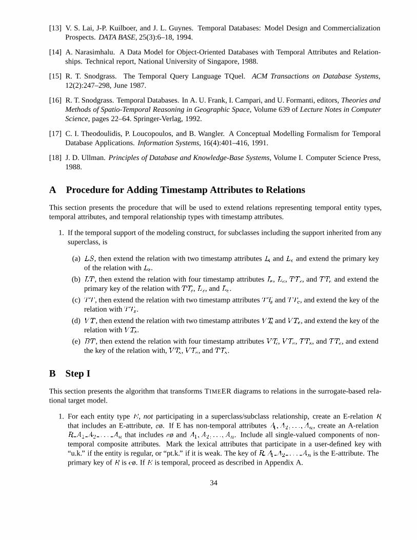
[13] V. S. Lai, J-P. Kuilboer, and J. L. Guynes. Temporal Databases: Model Design and CommercializationProspects.DATA BASE, 25(3):6–18, 1994.
[14] A. Narasimhalu. A Data Model for Object-Oriented Databases with Temporal Attributes and Relation-ships. Technical report, National University of Singapore, 1988.
[15] R. T. Snodgrass. The Temporal Query Language TQuel.ACM Transactions on Database Systems,12(2):247–298, June 1987.
[16] R. T. Snodgrass. Temporal Databases. In A. U. Frank, I. Campari, and U. Formanti, editors,Theories andMethods of Spatio-Temporal Reasoning in Geographic Space, Volume 639 ofLecture Notes in ComputerScience, pages 22–64. Springer-Verlag, 1992.
[17] C. I. Theodoulidis, P. Loucopoulos, and B. Wangler. A Conceptual Modelling Formalism for TemporalDatabase Applications.Information Systems, 16(4):401–416, 1991.
[18] J. D. Ullman.Principles of Database and Knowledge-Base Systems, Volume I. Computer Science Press,1988.
A Procedure for Adding Timestamp Attributes to Relations
This section presents the procedure that will be used to extend relations representing temporal entity types,temporal attributes, and temporal relationship types with timestamp attributes.
1. If the temporal support of the modeling construct, for subclasses including the support inherited from anysuperclass, is
(a) LS, then extend the relation with two timestamp attributesLs andLe and extend the primary keyof the relation withLs.
(b) LT , then extend the relation with four timestamp attributesLs, Le, TTs, andTTe and extend theprimary key of the relation withTTs, Ls, andLe.
(c) TT , then extend the relation with two timestamp attributesTTs andTTe, and extend the key of therelation withTTs.
(d) V T , then extend the relation with two timestamp attributesV Ts andV Te, and extend the key of therelation withV Ts.
(e) BT , then extend the relation with four timestamp attributesV Ts, V Te, TTs, andTTe, and extendthe key of the relation with,V Ts, V Te, andTTs.
B Step I
This section presents the algorithm that transforms TIMEER diagrams to relations in the surrogate-based rela-tional target model.
1. For each entity typeE, not participating in a superclass/subclass relationship, create an E-relationRthat includes an E-attribute,eø. If E has non-temporal attributesA�� A�� � � �� An, create an A-relationR A� A� � � � An that includeseø andA�� A�� � � �� An. Include all single-valued components of non-temporal composite attributes. Mark the lexical attributes that participate in a user-defined key with“u.k.” if the entity is regular, or “pt.k.” if it is weak. The key ofR A� A� � � � An is the E-attribute. Theprimary key ofR is eø. If E is temporal, proceed as described in Appendix A.
34
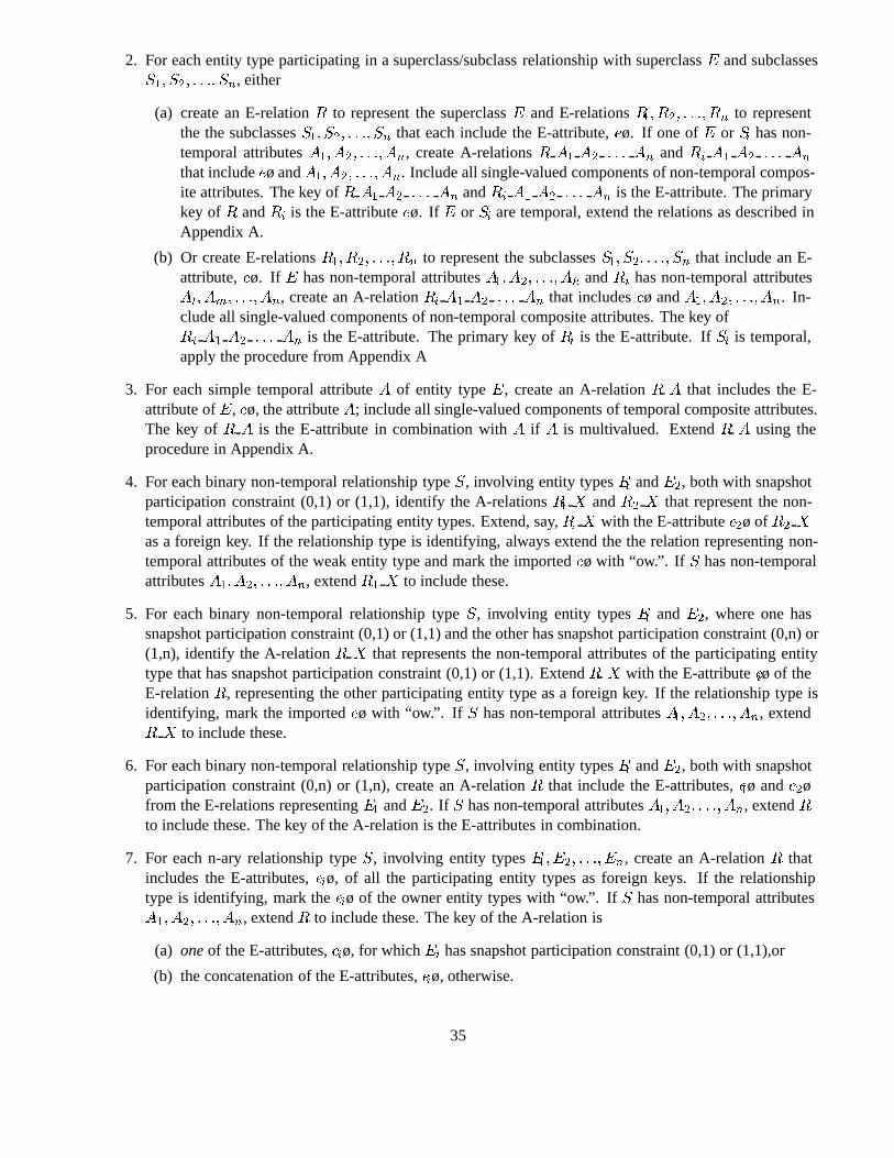
2. For each entity type participating in a superclass/subclass relationship with superclassE and subclassesS�� S�� � � �� Sn, either
(a) create an E-relationR to represent the superclassE and E-relationsR�� R�� � � �� Rn to representthe the subclassesS�� S�� � � �� Sn that each include the E-attribute,eø. If one ofE or Si has non-temporal attributesA�� A�� � � �� An, create A-relationsR A� A� � � � An andRi A� A� � � � An
that includeeø andA�� A�� � � �� An. Include all single-valued components of non-temporal compos-ite attributes. The key ofR A� A� � � � An andRi A� A� � � � An is the E-attribute. The primarykey ofR andRi is the E-attributeeø. If E or Si are temporal, extend the relations as described inAppendix A.
(b) Or create E-relationsR�� R�� � � �� Rn to represent the subclassesS�� S�� � � �� Sn that include an E-attribute,eø. If E has non-temporal attributesA�� A�� � � �� Ak andRi has non-temporal attributesAl� Am� � � �� An, create an A-relationRi A� A� � � � An that includeseø andA�� A�� � � �� An. In-clude all single-valued components of non-temporal composite attributes. The key ofRi A� A� � � � An is the E-attribute. The primary key ofRi is the E-attribute. IfSi is temporal,apply the procedure from Appendix A
3. For each simple temporal attributeA of entity typeE, create an A-relationR A that includes the E-attribute ofE, eø, the attributeA; include all single-valued components of temporal composite attributes.The key ofR A is the E-attribute in combination withA if A is multivalued. ExtendR A using theprocedure in Appendix A.
4. For each binary non-temporal relationship typeS, involving entity typesE� andE�, both with snapshotparticipation constraint (0,1) or (1,1), identify the A-relationsR� X andR� X that represent the non-temporal attributes of the participating entity types. Extend, say,R� X with the E-attributee�ø ofR� Xas a foreign key. If the relationship type is identifying, always extend the the relation representing non-temporal attributes of the weak entity type and mark the importedeø with “ow.”. If S has non-temporalattributesA�� A�� � � �� An, extendR� X to include these.
5. For each binary non-temporal relationship typeS, involving entity typesE� andE�, where one hassnapshot participation constraint (0,1) or (1,1) and the other has snapshot participation constraint (0,n) or(1,n), identify the A-relationR X that represents the non-temporal attributes of the participating entitytype that has snapshot participation constraint (0,1) or (1,1). ExtendR X with the E-attributeeiø of theE-relationR, representing the other participating entity type as a foreign key. If the relationship type isidentifying, mark the importedeø with “ow.”. If S has non-temporal attributesA�� A�� � � �� An, extendR X to include these.
6. For each binary non-temporal relationship typeS, involving entity typesE� andE�, both with snapshotparticipation constraint (0,n) or (1,n), create an A-relationR that include the E-attributes,e�ø ande�øfrom the E-relations representingE� andE�. If S has non-temporal attributesA�� A�� � � �� An, extendRto include these. The key of the A-relation is the E-attributes in combination.
7. For each n-ary relationship typeS, involving entity typesE�� E�� � � �� En, create an A-relationR thatincludes the E-attributes,eiø, of all the participating entity types as foreign keys. If the relationshiptype is identifying, mark theeiø of the owner entity types with “ow.”. IfS has non-temporal attributesA�� A�� � � �� An, extendR to include these. The key of the A-relation is
(a) oneof the E-attributes,eiø, for whichEi has snapshot participation constraint (0,1) or (1,1),or
(b) the concatenation of the E-attributes,eiø, otherwise.
35
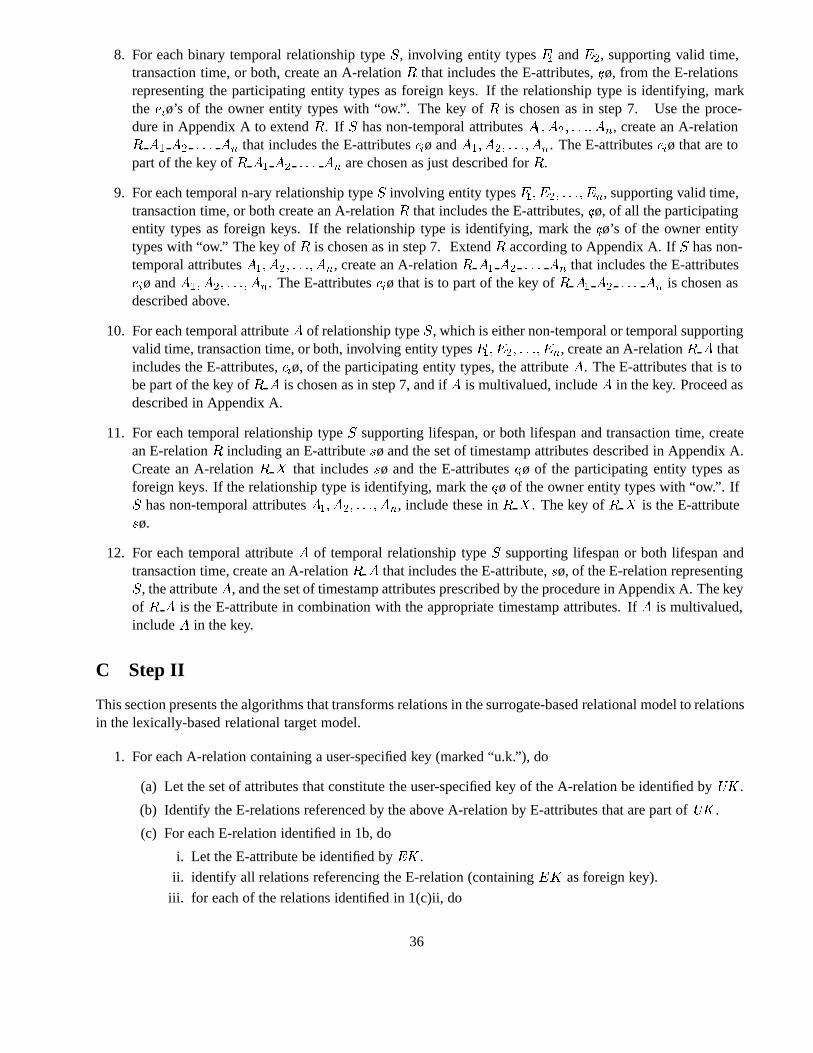
8. For each binary temporal relationship typeS, involving entity typesE� andE�, supporting valid time,transaction time, or both, create an A-relationR that includes the E-attributes,eiø, from the E-relationsrepresenting the participating entity types as foreign keys. If the relationship type is identifying, markthe eiø’s of the owner entity types with “ow.”. The key ofR is chosen as in step 7. Use the proce-dure in Appendix A to extendR. If S has non-temporal attributesA�� A�� � � �� An, create an A-relationR A� A� � � � An that includes the E-attributeseiø andA�� A�� � � �� An. The E-attributeseiø that are topart of the key ofR A� A� � � � An are chosen as just described forR.
9. For each temporal n-ary relationship typeS involving entity typesE�� E�� � � �� En, supporting valid time,transaction time, or both create an A-relationR that includes the E-attributes,eiø, of all the participatingentity types as foreign keys. If the relationship type is identifying, mark theeiø’s of the owner entitytypes with “ow.” The key ofR is chosen as in step 7. ExtendR according to Appendix A. IfS has non-temporal attributesA�� A�� � � �� An, create an A-relationR A� A� � � � An that includes the E-attributeseiø andA�� A�� � � �� An. The E-attributeseiø that is to part of the key ofR A� A� � � � An is chosen asdescribed above.
10. For each temporal attributeA of relationship typeS, which is either non-temporal or temporal supportingvalid time, transaction time, or both, involving entity typesE�� E�� � � �� En, create an A-relationR A thatincludes the E-attributes,eiø, of the participating entity types, the attributeA. The E-attributes that is tobe part of the key ofR A is chosen as in step 7, and ifA is multivalued, includeA in the key. Proceed asdescribed in Appendix A.
11. For each temporal relationship typeS supporting lifespan, or both lifespan and transaction time, createan E-relationR including an E-attributesø and the set of timestamp attributes described in Appendix A.Create an A-relationR X that includessø and the E-attributeseiø of the participating entity types asforeign keys. If the relationship type is identifying, mark theeiø of the owner entity types with “ow.”. IfS has non-temporal attributesA�� A�� � � �� An, include these inR X. The key ofR X is the E-attributesø.
12. For each temporal attributeA of temporal relationship typeS supporting lifespan or both lifespan andtransaction time, create an A-relationR A that includes the E-attribute,sø, of the E-relation representingS, the attributeA, and the set of timestamp attributes prescribed by the procedure in Appendix A. The keyof R A is the E-attribute in combination with the appropriate timestamp attributes. IfA is multivalued,includeA in the key.
C Step II
This section presents the algorithms that transforms relations in the surrogate-based relational model to relationsin the lexically-based relational target model.
1. For each A-relation containing a user-specified key (marked “u.k.”), do
(a) Let the set of attributes that constitute the user-specified key of the A-relation be identified byUK .
(b) Identify the E-relations referenced by the above A-relation by E-attributes that are part ofUK .
(c) For each E-relation identified in 1b, do
i. Let the E-attribute be identified byEK .
ii. identify all relations referencing the E-relation (containingEK as foreign key).
iii. for each of the relations identified in 1(c)ii, do
36
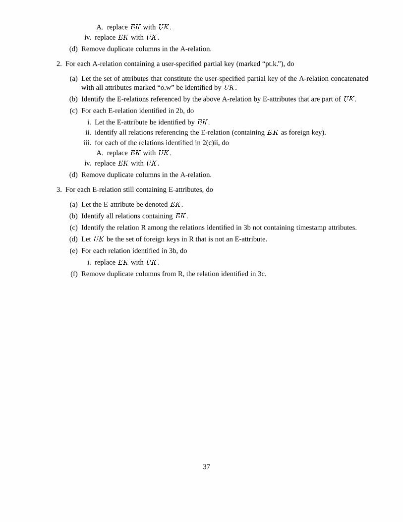
A. replaceEK with UK .
iv. replaceEK with UK .
(d) Remove duplicate columns in the A-relation.
2. For each A-relation containing a user-specified partial key (marked “pt.k.”), do
(a) Let the set of attributes that constitute the user-specified partial key of the A-relation concatenatedwith all attributes marked “o.w” be identified byUK .
(b) Identify the E-relations referenced by the above A-relation by E-attributes that are part ofUK .
(c) For each E-relation identified in 2b, do
i. Let the E-attribute be identified byEK .
ii. identify all relations referencing the E-relation (containingEK as foreign key).
iii. for each of the relations identified in 2(c)ii, do
A. replaceEK with UK .
iv. replaceEK with UK .
(d) Remove duplicate columns in the A-relation.
3. For each E-relation still containing E-attributes, do
(a) Let the E-attribute be denotedEK .
(b) Identify all relations containingEK .
(c) Identify the relation R among the relations identified in 3b not containing timestamp attributes.
(d) LetUK be the set of foreign keys in R that is not an E-attribute.
(e) For each relation identified in 3b, do
i. replaceEK with UK .
(f) Remove duplicate columns from R, the relation identified in 3c.
37