Embed Size (px)
Citation preview
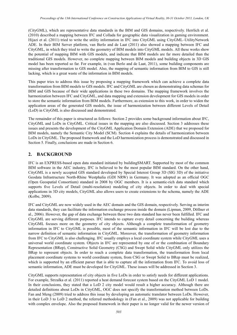
Proceedings of the 13th International Conference on Construction Applications of Virtual Reality, 30-31 October 2013, London, UK
MAPPING BETWEEN BIM MODELS AND 3D GIS CITY MODELS OF DIFFERENT LEVELS OF DETAIL1
Jack Cheng, Yichuan Deng & Qianru Du The Hong Kong University of Science and Technology
ABSTRACT: Modeling the built environment of a city digitally in three dimensions can support navigation, urban planning, disaster management, and energy consumption analysis. City Geography Markup Language (CityGML) was developed in recent years as a Geographic Information System (GIS) data standard to represent the geometry and geographical information of buildings in digital 3D city models. CityGML supports modeling on various Levels of Detail (LoDs) from simple box models to models with interior partitions. This paper presents the theoretical framework that we have developed for mapping between Building Information Modeling (BIM) models in the Industry Foundation Classes (IFC) format and CityGML models of different LoDs. The framework consists of two major parts – (1) transformation between BIM models and high level CityGML LoD4 models, and (2) harmonization among the four LoDs of CityGML. For the first part, a reference ontology was developed to transfer semantic information between BIM models in the IFC format and CityGML models. To reduce the file size of the generated CityGML models, a new geometric transformation algorithm was developed for the mapping from Swept Solid or Constructive Solid Geometry (CSG) representations, which are commonly used in BIM models, to Boundary Representation (BRep) which is used in CityGML models. For the second part, schema mediation techniques are used to convert CityGML models from one LoD to another LoD. Based on the reference ontology, an application domain extension (ADE) called “Semantic City Model (SCM)” was developed for CityGML. The SCM ADE enriches CityGML models by providing more semantic information such as the linkage relationship between walls and building stories. This paper presents the developed mapping framework with an illustrative example of a residential building.
KEYWORDS: 3D city models, Building Information Modeling (BIM), Geographic Information System (GIS), Industry Foundation Classes (IFC), Schema mapping
1. INTRODUCTION
Modeling city objects in 3D environments can improve the capabilities of Geographic Information Systems (GIS). The traditional 2D GIS does not support applications that require the data of object height or elevation, such as indoor ventilation modeling or indoor navigation. By 3D modeling the GIS can provide analysis results on the scale of “rooms” or “spaces” rather than “districts” or building blocks. Moreover, some simulations performed on GIS also require the 3D details of building interior. For example, Strzalka et al. (2011) showed an urban scale heating energy demand forecasting system based on 3D GIS models. Given the demand for those indoor 3D data of buildings, however, the acquisition of such data is hard due to the fact that there are many hidden components in the building which are not able to be discovered by traditional ways such as laser scanning. In this sense, 3D models from Building Information Modeling (BIM) can serve as data source for constructing 3D GIS city models.
BIM is the process to create, store and manage relevant data of a building throughout its whole lifecycle (Eastman et al., 2008). BIM models are data rich models which not only represent the geometry of building components, but also assign attributes to them. Semantic information such as owner, construction time and cost is available from BIM models. As an emerging technology in the Architecture, Engineering and Construction (AEC) domain, BIM is now getting wider and wider adoptions. This provides the possibility and availability of BIM models as the data source for GIS. Besides providing 3D building geometry information, BIM can extend the data richness of GIS models by providing semantic information of building components.
Feeding information of BIM to GIS models involves the process of automatic transformation of BIM data into GIS data, including schema harmonization and data mapping between BIM and GIS data standards. There have been a number of studies concerning this topic. El-Mekawy et al. (2011) proposed an ontology called the Unified Building Model (UBM) to merge Industry Foundation Classes (IFC) and City Geography Markup Language
1 Citation: Cheng, J., Deng, Y. & Du, Q. (2013). Mapping between BIM models and 3D GIS city models of different levels of detail. In: N. Dawood and M. Kassem (Eds.), Proceedings of the 13th International Conference on Construction Applications of Virtual Reality, 30-31 October 2013, London, UK.
502
Proceedings of the 13th International Conference on Construction Applications of Virtual Reality, 30-31 October 2013, London, UK
(CityGML), which are representative data standards in the BIM and GIS domains, respectively. Herrlich et al. (2010) described a mapping between IFC and Collada for geographic data visualization in gaming environment. Hijazi et al. (2011) tried to write the utility information in IFC into CityGML using CityGML–UtilityNetwork ADE. In their BIM Server platform, van Berlo and de Laat (2011) also showed a mapping between IFC and CityGML, in which they tried to write the geometry of BIM models into CityGML models. All these works show the potential of mapping BIM with GIS models, and indicate that BIM models are far more detailed than the traditional GIS models. However, no complete mapping between BIM models and building objects in 3D GIS model has been reported so far. For example, in (van Berlo and de Laat, 2011), some building components are missing after transformation to GIS model. Also, the mapping of semantic information from BIM to GIS is still lacking, which is a great waste of the information in BIM models.
This paper tries to address this issue by proposing a mapping framework which can achieve a complete data transformation from BIM models to GIS models. IFC and CityGML are chosen as demonstrating data schemas for BIM and GIS because of their wide applications in these two domains. The mapping framework involves the harmonization between IFC and CityGML, and data mapping and extension development for GIS models in order to store the semantic information from BIM models. Furthermore, as extension to this work, in order to widen the application areas of the generated GIS models, the issue of harmonization between different Levels of Detail (LoD) in CityGML is also discussed and demonstrated.
The remainder of this paper is structured as follows: Section 2 provides some background information about IFC, CityGML and LoDs in CityGML. Critical issues in the mapping are also discussed. Section 3 addresses these issues and presents the development of the CityGML Application Domain Extension (ADE) that we proposed for BIM models, namely the Semantic City Model (SCM). Section 4 explains the details of harmonization between LoDs in CityGML. The proposed framework and the LoD harmonization process is demonstrated and discussed in Section 5. Finally, conclusions are made in Section 6.
2. BACKGROUND
IFC is an EXPRESS-based open data standard initiated by buildingSMART. Supported by most of the common BIM software in the AEC industry, IFC is believed to be the most popular BIM standard. On the other hand, CityGML is a newly accepted GIS standard developed by Special Interest Group 3D (SIG 3D) of the initiative Geodata Infrastructure North-Rhine Westphalia (GDI NRW) in Germany. It was adopted as an official OGC (Open Geospatial Consortium) standard in 2008 by OGC members. It is a semantic-rich data standard which supports five Levels of Detail (multi-resolution) modeling of city objects. In order to deal with special applications in 3D city models, CityGML also allows users to create extensions to the schema, namely the ADE (Kolbe, 2009).
IFC and CityGML are now widely used in the AEC domain and the GIS domain, respectively. Serving as interim data standards, they can facilitate the information exchange process inside the domain (Lipman, 2009, Döllner et al., 2006). However, the gap of data exchange between these two data standard has never been fulfilled. IFC and CityGML are serving different purposes. IFC intends to capture every detail concerning the building whereas CityGML focuses more on the geometry of city objects. Although a complete transformation of geometry information in IFC to CityGML is possible, most of the semantic information in IFC will be lost due to the narrow definition of semantic information in CityGML. Moreover, the transformation of geometry information from IFC to CityGML is also challenging. IFC usually employs a local coordinate system while CityGML uses a universal world coordinate system. Objects in IFC are represented by one of or the combination of Boundary Representation (BRep), Constructive Solid Geometry (CSG) and Swept Solid while CityGML only utilizes the BRep to represent objects. In order to reach a complete data transformation, the transformation from local placement coordinate systems to world coordinate system, from CSG or Swept Solid to BRep must be realized, which is supported by an efficient parser that is able to capture all the information from IFC. To avoid loss of semantic information, ADE must be developed for CityGML. These issues will be addressed in Section 3.
CityGML supports representation of city objects in five LoDs in order to satisfy needs for different applications. For example, Strzalka et al. (2011) reported a heat demand forecast system based on the CityGML LoD 1 model. In their conclusions, they stated that a LoD 2 city model would result a higher accuracy. Although there are detailed definitions about LoDs in CityGML, OGC does not specify the transformation method between LoDs. Fan and Meng (2009) tried to address this issue by developing an automatic translator between LoDs. However, in their LoD 3 to LoD 2 method, the referred methodology in (Fan et al., 2009) was not applicable for building with complex envelope. Also the proposed framework in their paper is no longer valid for the newer version of
503
Proceedings of the 13th International Conference on Construction Applications of Virtual Reality, 30-31 October 2013, London, UK
CityGML. In Section 4 of this paper, we will propose new transformation methods for LoD 3 to LoD 2 and present an automatic transformation between all LoDs.
3. FRAMEWORK FOR TRANSFORMATION FROM IFC TO CITYGML
3.1. Overview
IFC employs the EXPRESS data modeling language to represent building objects, in which all the relationships between objects such as “contained in” or “structural member of” are clearly defined. These relationships are called “inverse attributes” in IFC schema. Inverse attributes are important for developing the parser for IFC. For example, getting the “contained in” attributes of a building will result in getting all the components belonging to the building. Inverse attributes are also important attributes for building objects. van Berlo and de Laat (2011) proposed an ADE called GeoBIM for CityGML in which they defined some semantic information from IFC for CityGML. However, they did not considered the inverse relationships in the ADE and thus losing a lot of information about relationships of objects from BIM models. El-Mekawy et al. (2011) developed a Unified Building Model to mapping BIM with CityGML. But inverse attributes were not considered either. Our framework starts with developing the parser for IFC and CityGML using inverse attributes. Then the transformation of local coordinate system and CSG/Swept Solid is used in the data processing stage. CityGML models with semantic information are generated using the proposed ADE called Semantic City Model (SCM).
3.2. Parser Strategy
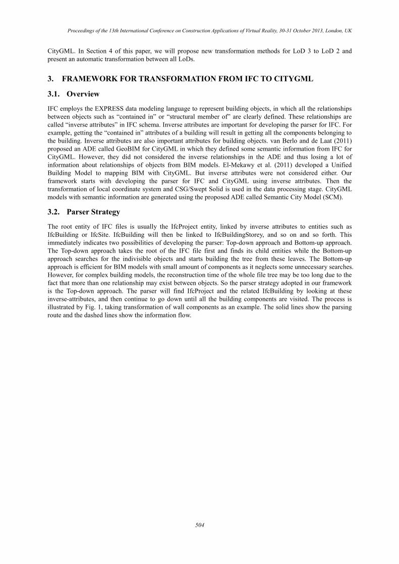
The root entity of IFC files is usually the IfcProject entity, linked by inverse attributes to entities such as IfcBuilding or IfcSite. IfcBuilding will then be linked to IfcBuildingStorey, and so on and so forth. This immediately indicates two possibilities of developing the parser: Top-down approach and Bottom-up approach. The Top-down approach takes the root of the IFC file first and finds its child entities while the Bottom-up approach searches for the indivisible objects and starts building the tree from these leaves. The Bottom-up approach is efficient for BIM models with small amount of components as it neglects some unnecessary searches. However, for complex building models, the reconstruction time of the whole file tree may be too long due to the fact that more than one relationship may exist between objects. So the parser strategy adopted in our framework is the Top-down approach. The parser will find IfcProject and the related IfcBuilding by looking at these inverse-attributes, and then continue to go down until all the building components are visited. The process is illustrated by Fig. 1, taking transformation of wall components as an example. The solid lines show the parsing route and the dashed lines show the information flow.
504
Proceedings of the 13th International Conference on Construction Applications of Virtual Reality, 30-31 October 2013, London, UK
Read IfcProject
Read IfcProject
and iterate
and iterate
IFC File Input
IFC File Input
IfcProject
IfcProject
Exists
Exists
?
?
Yes
Yes
Read IfcSite and
Read IfcSite and
iterate
iterate
IfcSite
IfcSite
Exists
Exists
?
?
No
No
Yes
Yes
Read
Read
IfcBuilding and
IfcBuilding and
iterate
iterate
IfcBuilding
IfcBuilding
Exists
Exists
?
?
No
No
Yes
Yes
Read IfcBuilding-
Storey and iterate
IfcBuildingSt
orey Exists?
No
Read Building
Components on
the Storey
Read IfcWall
and Iterate
Read Global Read Global
ID
ID
,
,
NAME
NAME
,
,
DESCRIPTOIN
DESCRIPTOIN
Loop for
Loop for
Each Wall
Each Wall
Write Building Object
Read Inverse
Read Inverse
Relationship
Relationship
Write Inverse Relationship
Read
Read
IfcObjectPlace
IfcObjectPlace
ment
ment
Write Geometry.
Object
ID and Geometry.
Coordinate
Transformation Matrix
Read IfcProductRepre
sentation
Write Boundary Surfaces.Coordinates
Read Property
Sets containing
this wall
Write Information
About PropertySets
CityGML File Writing
Generate WallSurface
Write Inverse
Relationship
and Wall Relationship
Write Geometry.Boun
darySurface into _Multisurface
Write PropertySets
CityGML File
CityGML File
Output
Output
Parsing Route Information Flow
Fig. 1: Overview of data mapping process
3.3. Data processing: Transformation of local placement system and CSG/Swept Solid
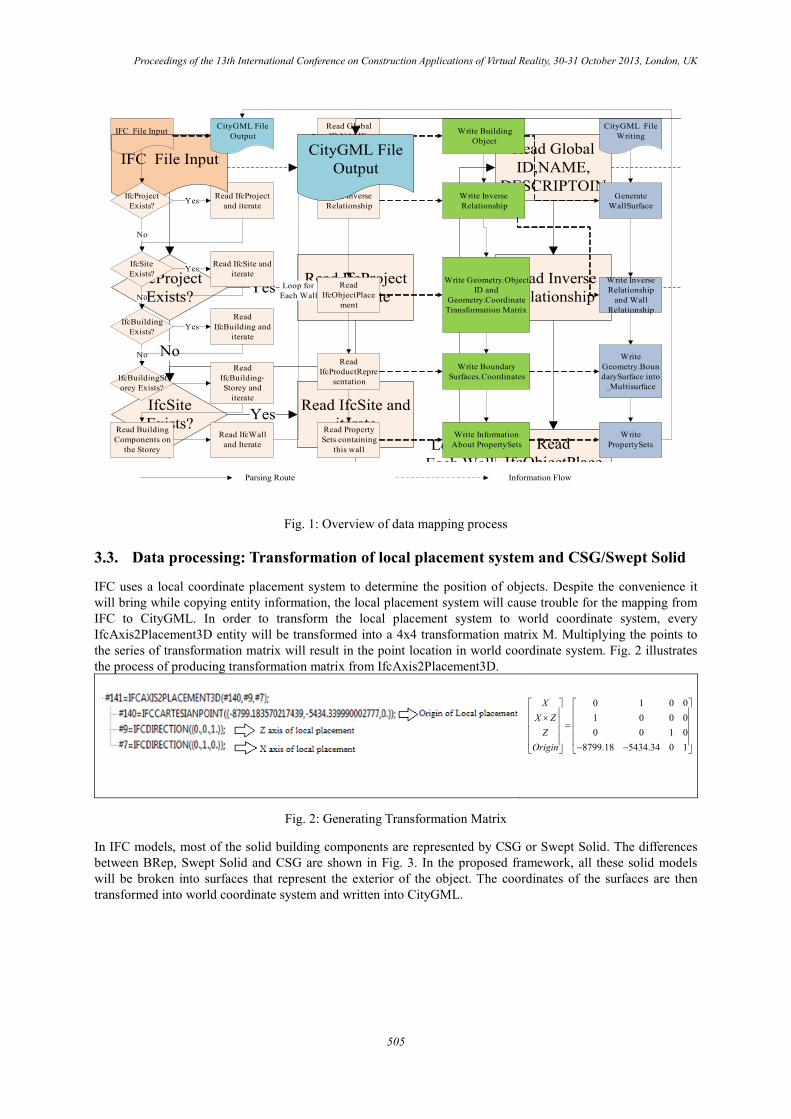
IFC uses a local coordinate placement system to determine the position of objects. Despite the convenience it will bring while copying entity information, the local placement system will cause trouble for the mapping from IFC to CityGML. In order to transform the local placement system to world coordinate system, every IfcAxis2Placement3D entity will be transformed into a 4x4 transformation matrix M. Multiplying the points to the series of transformation matrix will result in the point location in world coordinate system. Fig. 2 illustrates the process of producing transformation matrix from IfcAxis2Placement3D.
0 1 0 01 0 0 00 0 1 0
8799.18 5434.34 0 1
XX Z
ZOrigin
× = − −
Fig. 2: Generating Transformation Matrix
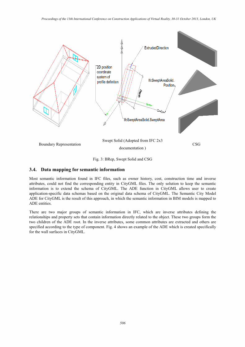
In IFC models, most of the solid building components are represented by CSG or Swept Solid. The differences between BRep, Swept Solid and CSG are shown in Fig. 3. In the proposed framework, all these solid models will be broken into surfaces that represent the exterior of the object. The coordinates of the surfaces are then transformed into world coordinate system and written into CityGML.
505
Proceedings of the 13th International Conference on Construction Applications of Virtual Reality, 30-31 October 2013, London, UK
Boundary Representation Swept Solid (Adopted from IFC 2x3
documentation ) CSG
Fig. 3: BRep, Swept Solid and CSG
3.4. Data mapping for semantic information
Most semantic information found in IFC files, such as owner history, cost, construction time and inverse attributes, could not find the corresponding entity in CityGML files. The only solution to keep the semantic information is to extend the schema of CityGML. The ADE function in CityGML allows user to create application-specific data schemas based on the original data schema of CityGML. The Semantic City Model ADE for CityGML is the result of this approach, in which the semantic information in BIM models is mapped to ADE entities.
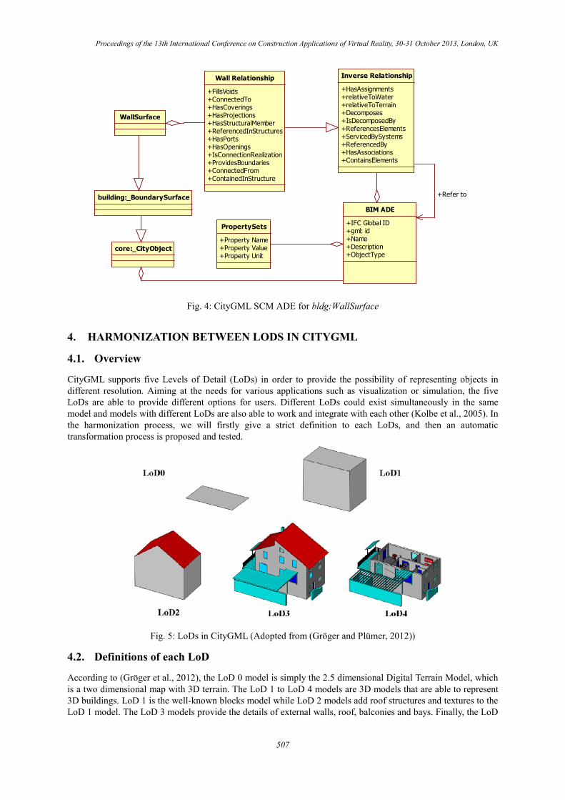
There are two major groups of semantic information in IFC, which are inverse attributes defining the relationships and property sets that contain information directly related to the object. These two groups form the two children of the ADE root. In the inverse attributes, some common attributes are extracted and others are specified according to the type of component. Fig. 4 shows an example of the ADE which is created specifically for the wall surfaces in CityGML.
506
Proceedings of the 13th International Conference on Construction Applications of Virtual Reality, 30-31 October 2013, London, UK
Fig. 4: CityGML SCM ADE for bldg:WallSurface
4. HARMONIZATION BETWEEN LODS IN CITYGML
4.1. Overview
CityGML supports five Levels of Detail (LoDs) in order to provide the possibility of representing objects in different resolution. Aiming at the needs for various applications such as visualization or simulation, the five LoDs are able to provide different options for users. Different LoDs could exist simultaneously in the same model and models with different LoDs are also able to work and integrate with each other (Kolbe et al., 2005). In the harmonization process, we will firstly give a strict definition to each LoDs, and then an automatic transformation process is proposed and tested.
Fig. 5: LoDs in CityGML (Adopted from (Gröger and Plümer, 2012))
4.2. Definitions of each LoD
According to (Gröger et al., 2012), the LoD 0 model is simply the 2.5 dimensional Digital Terrain Model, which is a two dimensional map with 3D terrain. The LoD 1 to LoD 4 models are 3D models that are able to represent 3D buildings. LoD 1 is the well-known blocks model while LoD 2 models add roof structures and textures to the LoD 1 model. The LoD 3 models provide the details of external walls, roof, balconies and bays. Finally, the LoD
BIM ADE
+IFC Global ID+gml: id+Name+Description+ObjectType
Inverse Relationship
+HasAssignments+relativeToWater+relativeToTerrain+Decomposes+IsDecomposedBy+ReferencesElements+ServicedBySystems+ReferencedBy+HasAssociations+ContainsElements
PropertySets
+Property Name+Property Value+Property Unit
+Refer to
Wall Relationship
+FillsVoids+ConnectedTo+HasCoverings+HasProjections+HasStructuralMember+ReferencedInStructures+HasPorts+HasOpenings+IsConnectionRealization+ProvidesBoundaries+ConnectedFrom+ContainedInStructure
core:_CityObject
building:_BoundarySurface
WallSurface
507
Proceedings of the 13th International Conference on Construction Applications of Virtual Reality, 30-31 October 2013, London, UK
4 model completes a LoD 3 model by adding interior building components such as rooms and furniture. Fig. 5 shows an overview of LoDs.
Until now OGC does not give a strict definition of LoDs in CityGML, so users could generate models based on their own understanding about the LoDs. However, this flexibility can also be seen as a drawback as there are no rules about whether certain objects should exist in a specific LoD model or not (Gröger and Plümer, 2012). The first step of the harmonization would be defining each LoD in detail. As we are dealing with 3D building models, only LoD 1-4 is considered.
It is not easy to give a strict definition for each LoD as the scope of source references is narrow. We analyze the definitions of LoDs based on the following sources:
A. CityGML specifications and encoding standard from OGC, such as (Gröger et al., 2008, Gröger et al., 2012).
B. Data sets recommended by the official CityGML website. By analyzing different LoDs, whether one entity exists in certain LoD can be determined. If conflict occurs, we refer to first source.
C. Papers about CityGML and Levels of Detail in 3D GIS models, such as (Fan and Meng, 2009, Gröger and Plümer, 2012, Döllner and Buchholz, 2005).
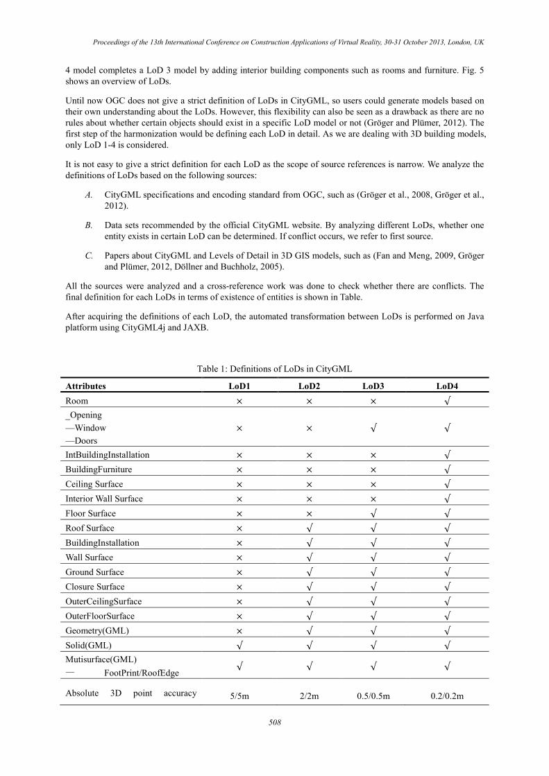
All the sources were analyzed and a cross-reference work was done to check whether there are conflicts. The final definition for each LoDs in terms of existence of entities is shown in Table.
After acquiring the definitions of each LoD, the automated transformation between LoDs is performed on Java platform using CityGML4j and JAXB.
Table 1: Definitions of LoDs in CityGML
Attributes LoD1 LoD2 LoD3 LoD4 Room × × × √ _Opening —Window —Doors
× × √ √
IntBuildingInstallation × × × √ BuildingFurniture × × × √ Ceiling Surface × × × √ Interior Wall Surface × × × √ Floor Surface × × √ √ Roof Surface × √ √ √ BuildingInstallation × √ √ √ Wall Surface × √ √ √ Ground Surface × √ √ √ Closure Surface × √ √ √ OuterCeilingSurface × √ √ √ OuterFloorSurface × √ √ √ Geometry(GML) × √ √ √ Solid(GML) √ √ √ √ Mutisurface(GML) — FootPrint/RoofEdge √ √ √ √
Absolute 3D point accuracy 5/5m 2/2m 0.5/0.5m 0.2/0.2m
508
Proceedings of the 13th International Conference on Construction Applications of Virtual Reality, 30-31 October 2013, London, UK
Attributes LoD1 LoD2 LoD3 LoD4 (position / height)
Roof structure/representation flat differentiated roof structures
real object form
real object form
Roof overhanging parts no yes, if known yes yes
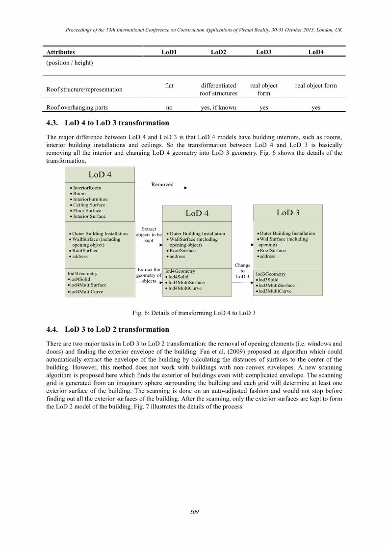
4.3. LoD 4 to LoD 3 transformation
The major difference between LoD 4 and LoD 3 is that LoD 4 models have building interiors, such as rooms, interior building installations and ceilings. So the transformation between LoD 4 and LoD 3 is basically removing all the interior and changing LoD 4 geometry into LoD 3 geometry. Fig. 6 shows the details of the transformation.
LoD 4• InteriorRoom• Room• InteriorFurniture• Ceiling Surface• Floor Surface• Interior Surface
• Outer Building Installation• WallSurface (including
opening object)• RoofSurface• address
•Outer Building Installation•WallSurface (including opening)•RoofSurface•address
Removed
Extract objects to be
kept
LoD 4
lod4Geometry• lod4Solid• lod4MultiSurface• lod4MultiCurve
LoD 3
Change to
LoD 3lod4Geometry•lod4Solid•lod4MultiSurface•lod4MultiCurve
Extract the geometry of
objectslod3Geometry•lod3Solid•lod3MultiSurface•lod3MultiCurve
• Outer Building Installation• WallSurface (including
opening object)• RoofSurface• address
Fig. 6: Details of transforming LoD 4 to LoD 3
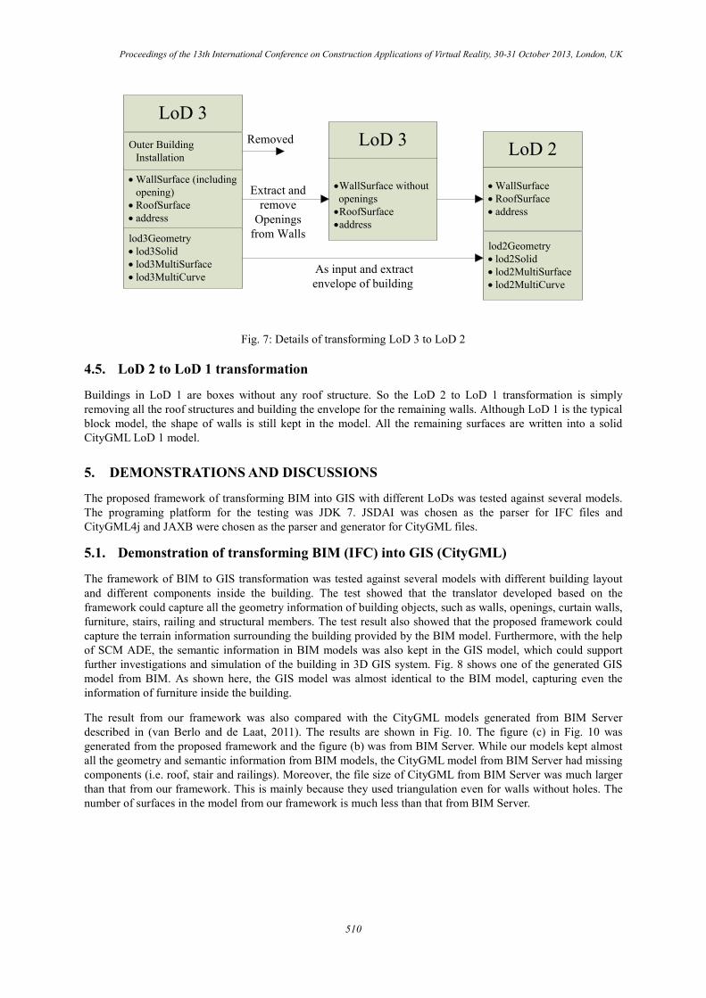
4.4. LoD 3 to LoD 2 transformation
There are two major tasks in LoD 3 to LoD 2 transformation: the removal of opening elements (i.e. windows and doors) and finding the exterior envelope of the building. Fan et al. (2009) proposed an algorithm which could automatically extract the envelope of the building by calculating the distances of surfaces to the center of the building. However, this method does not work with buildings with non-convex envelopes. A new scanning algorithm is proposed here which finds the exterior of buildings even with complicated envelope. The scanning grid is generated from an imaginary sphere surrounding the building and each grid will determine at least one exterior surface of the building. The scanning is done on an auto-adjusted fashion and would not stop before finding out all the exterior surfaces of the building. After the scanning, only the exterior surfaces are kept to form the LoD 2 model of the building. Fig. 7 illustrates the details of the process.
509
Proceedings of the 13th International Conference on Construction Applications of Virtual Reality, 30-31 October 2013, London, UK
•WallSurface without openings
•RoofSurface•address
Extract and remove
Openings from Walls
LoD 3
As input and extract envelope of building
Removed LoD 2
• WallSurface• RoofSurface• address
LoD 3
• WallSurface (including opening)
• RoofSurface• address
lod3Geometry• lod3Solid• lod3MultiSurface• lod3MultiCurve
lod2Geometry• lod2Solid• lod2MultiSurface• lod2MultiCurve
Outer Building Installation
Fig. 7: Details of transforming LoD 3 to LoD 2
4.5. LoD 2 to LoD 1 transformation
Buildings in LoD 1 are boxes without any roof structure. So the LoD 2 to LoD 1 transformation is simply removing all the roof structures and building the envelope for the remaining walls. Although LoD 1 is the typical block model, the shape of walls is still kept in the model. All the remaining surfaces are written into a solid CityGML LoD 1 model.
5. DEMONSTRATIONS AND DISCUSSIONS
The proposed framework of transforming BIM into GIS with different LoDs was tested against several models. The programing platform for the testing was JDK 7. JSDAI was chosen as the parser for IFC files and CityGML4j and JAXB were chosen as the parser and generator for CityGML files.
5.1. Demonstration of transforming BIM (IFC) into GIS (CityGML)
The framework of BIM to GIS transformation was tested against several models with different building layout and different components inside the building. The test showed that the translator developed based on the framework could capture all the geometry information of building objects, such as walls, openings, curtain walls, furniture, stairs, railing and structural members. The test result also showed that the proposed framework could capture the terrain information surrounding the building provided by the BIM model. Furthermore, with the help of SCM ADE, the semantic information in BIM models was also kept in the GIS model, which could support further investigations and simulation of the building in 3D GIS system. Fig. 8 shows one of the generated GIS model from BIM. As shown here, the GIS model was almost identical to the BIM model, capturing even the information of furniture inside the building.
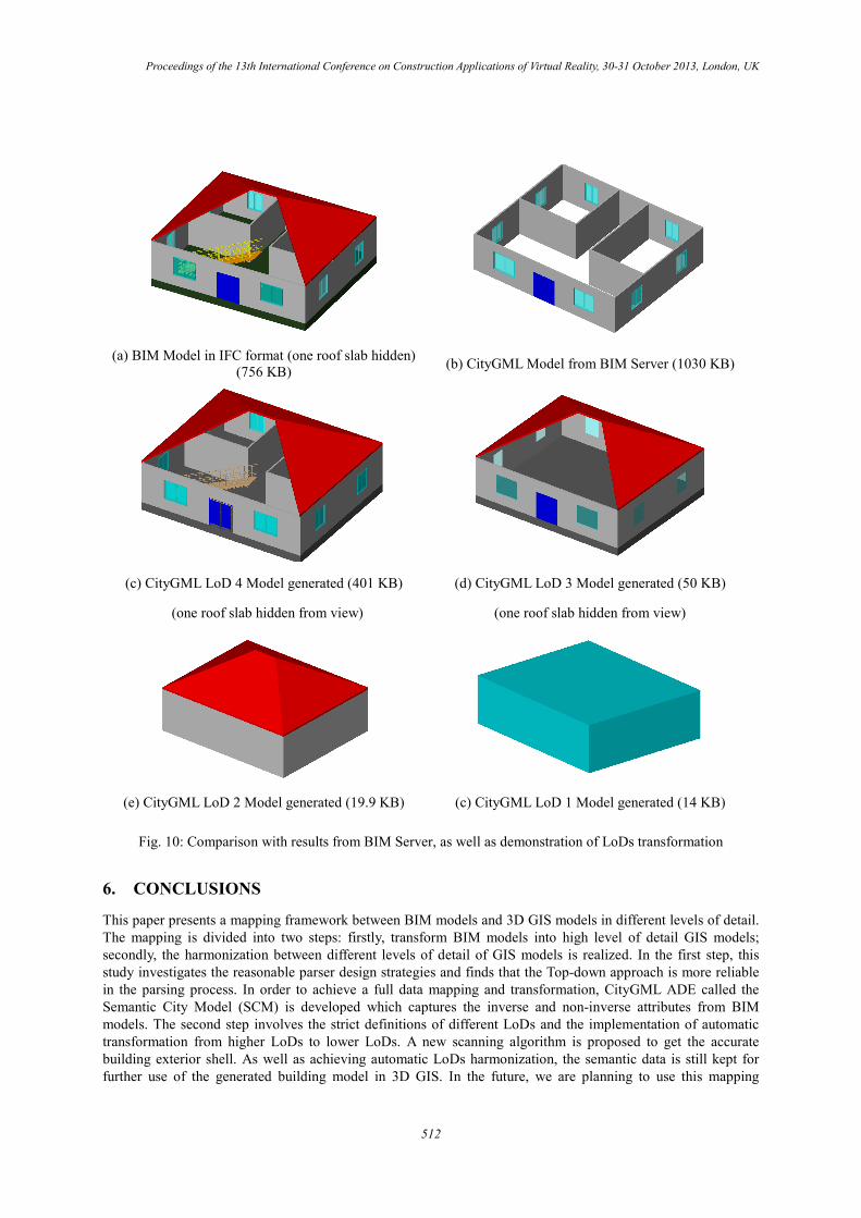
The result from our framework was also compared with the CityGML models generated from BIM Server described in (van Berlo and de Laat, 2011). The results are shown in Fig. 10. The figure (c) in Fig. 10 was generated from the proposed framework and the figure (b) was from BIM Server. While our models kept almost all the geometry and semantic information from BIM models, the CityGML model from BIM Server had missing components (i.e. roof, stair and railings). Moreover, the file size of CityGML from BIM Server was much larger than that from our framework. This is mainly because they used triangulation even for walls without holes. The number of surfaces in the model from our framework is much less than that from BIM Server.
510
Proceedings of the 13th International Conference on Construction Applications of Virtual Reality, 30-31 October 2013, London, UK
BIM Model in IFC (1024 KB) GIS Model Generated (4027 KB)
Fig. 8: Test result of the framework: BIM model (left) and GIS model (right)
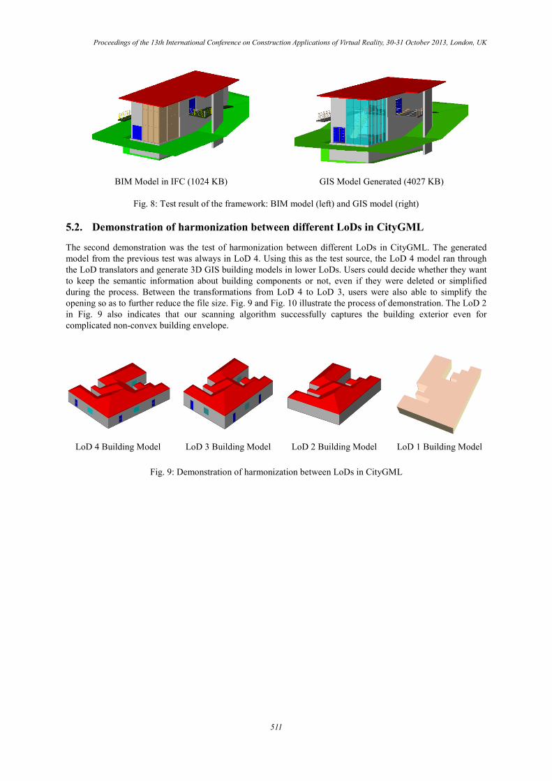
5.2. Demonstration of harmonization between different LoDs in CityGML
The second demonstration was the test of harmonization between different LoDs in CityGML. The generated model from the previous test was always in LoD 4. Using this as the test source, the LoD 4 model ran through the LoD translators and generate 3D GIS building models in lower LoDs. Users could decide whether they want to keep the semantic information about building components or not, even if they were deleted or simplified during the process. Between the transformations from LoD 4 to LoD 3, users were also able to simplify the opening so as to further reduce the file size. Fig. 9 and Fig. 10 illustrate the process of demonstration. The LoD 2 in Fig. 9 also indicates that our scanning algorithm successfully captures the building exterior even for complicated non-convex building envelope.
LoD 4 Building Model LoD 3 Building Model LoD 2 Building Model LoD 1 Building Model
Fig. 9: Demonstration of harmonization between LoDs in CityGML
511
Proceedings of the 13th International Conference on Construction Applications of Virtual Reality, 30-31 October 2013, London, UK
(a) BIM Model in IFC format (one roof slab hidden)
(756 KB) (b) CityGML Model from BIM Server (1030 KB)
(c) CityGML LoD 4 Model generated (401 KB)
(one roof slab hidden from view)
(d) CityGML LoD 3 Model generated (50 KB)
(one roof slab hidden from view)
(e) CityGML LoD 2 Model generated (19.9 KB) (c) CityGML LoD 1 Model generated (14 KB)
Fig. 10: Comparison with results from BIM Server, as well as demonstration of LoDs transformation
6. CONCLUSIONS
This paper presents a mapping framework between BIM models and 3D GIS models in different levels of detail. The mapping is divided into two steps: firstly, transform BIM models into high level of detail GIS models; secondly, the harmonization between different levels of detail of GIS models is realized. In the first step, this study investigates the reasonable parser design strategies and finds that the Top-down approach is more reliable in the parsing process. In order to achieve a full data mapping and transformation, CityGML ADE called the Semantic City Model (SCM) is developed which captures the inverse and non-inverse attributes from BIM models. The second step involves the strict definitions of different LoDs and the implementation of automatic transformation from higher LoDs to lower LoDs. A new scanning algorithm is proposed to get the accurate building exterior shell. As well as achieving automatic LoDs harmonization, the semantic data is still kept for further use of the generated building model in 3D GIS. In the future, we are planning to use this mapping
512
Proceedings of the 13th International Conference on Construction Applications of Virtual Reality, 30-31 October 2013, London, UK
framework for simulations and investigations of sustainable city design. Using BIM as data source, it is believed that such simulations could achieve higher accuracy.
7. ACKNOWLEDGEMENTS
The authors would like to acknowledge the support by the Hong Kong Research Grants Council, Grant No. 622812. Any opinions and findings are those of the authors, and do not necessarily reflect the views of the Hong Kong Research Grants Council.
8. REFERENCES
Döllner, J. & Buchholz, H. Continuous level-of-detail modeling of buildings in 3D city models. Proceedings of the 13th annual ACM international workshop on Geographic information systems, 2005 Bremen, Germany. Association for Computing Machinery, 173-181.
Döllner, J., Kolbe, T. H., Liecke, F., Sgouros, T. & Teichmann, K. The Virtual 3D City Model of Berlin-Managing, Integrating, and Communicating Complex Urban Information. Proceedings of the 25th Urban Data Management Symposium (UDMS), 2006 Aalborg, Denmark. 15-17.
Eastman, C., Teicholz, P., Sacks, R. & Liston, K. 2008. BIM Handbook: A Guide to Building Information Modeling for Owners, Managers, Designers, Engineers and Contractors, Wiley Publishing.
El-Mekawy, M., stman, A. & Shahzad, K. 2011. Towards Interoperating CityGML and IFC Building Models: A Unified Model Based Approach. In: Kolbe, T. H., König, G. & Nagel, C. (eds.) Advances in 3D Geo-Information Sciences. Berlin Heidelberg: Springer 73-93.
Fan, H. & Meng, L. Automatic derivation of different levels of detail for 3D buildings modeled by CityGML. Proceedings of 24th international cartography conference (ICC2009), 2009 Santiago Chile. 15-21.
Fan, H., Meng, L. & Jahnke, M. 2009. Generalization of 3D buildings modelled by CityGML. Advances in GIScience. Springer, 387-405.
Gröger, G., Kolbe, T. H., Czerwinski, A. & Nagel, C. 2008. OpenGIS city geography markup language (CityGML) encoding standard, Open Geospatial Consortium Inc. .
Gröger, G., Kolbe, T. H., Nagel, C. & Häfele, K.-H. 2012. OpenGIS City Geography Markup Language Encoding Standard 2.0, Open Geospatial Consortium Inc. .
Gröger, G. & Plümer, L. 2012. CityGML–Interoperable semantic 3D city models. ISPRS Journal of Photogrammetry and Remote Sensing, Vol. 71, 12-33.
Herrlich, M., Holle, H. & Malaka, R. 2010. Integration of CityGML and Collada for High-Quality Geographic Data Visualization on the PC and Xbox 360. In: Yang, H., Malaka, R., Hoshino, J. & Han, J. (eds.) Lecture Notes in Computer Science. Berlin / Heidelberg: Springer 270-277.
Hijazi, I., Ehlers, M., Zlatanova, S., Becker, T. & Berlo, L. 2011. Initial investigations for modeling interior Utilities within 3D Geo Context: Transforming IFC-interior utility to CityGML/UtilityNetworkADE. Advances in 3D Geo-Information Sciences. Springer, 95-113.
Kolbe, T. 2009. Representing and Exchanging 3D City Models with CityGML. In: Lee, J. & Zlatanova, S. (eds.) 3D Geo-Information Sciences. Springer Berlin Heidelberg, 15-31.
Kolbe, T. H., Gröger, G. & Plümer, L. 2005. CityGML: Interoperable access to 3D city models. Geo-information for disaster management. Springer, 883-899.
Lipman, R. 2009. Details of the mapping between the CIS/2 and IFC product data models for structural steel. Journal of Information Technology in Construction, Vol. 14, 1-13.
Strzalka, A., Bogdahn, J., Coors, V. & Eicker, U. 2011. 3D City modeling for urban scale heating energy demand forecasting. HVAC&R Research, Vol. 17, 526-539.
513

Proceedings of the 13th International Conference on Construction Applications of Virtual Reality, 30-31 October 2013, London, UK
Van Berlo, L. & De Laat, R. 2011. Integration of BIM and GIS: The development of the CityGML GeoBIM extension. In: Kolbe, T. H., König, G. & Nagel, C. (eds.) Advances in 3D Geo-Information Sciences. Berlin Heidelberg: Springer, 211-227
514