Embed Size (px)
Citation preview
MINES ParisTech Centre de Recherche sur les Risques et les Crises
Rue Claude Daunesse, CS 10207, 06904 Sophia Antipolis Cedex
présentée et soutenue publiquement par
Jaleh SAMADI
le 14 décembre 2012
Development of a Systemic Risk Management Approach for
CO2 Capture, Transport and Storage Projects
Doctorat ParisTech
T H È S E
pour obtenir le grade de docteur délivré par
l’École nationale supérieure des mines de Paris
Spécialité “Sciences et Génie des Activités à Risques”
Directeur de thèse : Emmanuel GARBOLINO
Jury Mme. Nancy LEVESON, Professeur, Massachusetts Institute of Technology Rapporteur M. Laurent PERRIN, Professeur, ENSIC Rapporteur M. Didier GRAILLOT, Dr. HDR, EMSE Examinateur M. Marc POUMADERE, Dr., Institut Symlog Examinateur Mme. Nadège LABAT, Ingénieur HSE Management, TOTAL Invité M. Emmanuel GARBOLINO, Dr. HDR, MINES ParisTech Directeur de thèse
Ecole doctorale n° 432 : Sciences et Métiers de l’Ingénieur
T
H
E
S
E

MINES ParisTech Centre de Recherche sur les Risques et les Crises
Rue Claude Daunesse, CS 10207, 06904 Sophia Antipolis Cedex
[Page intentionally left blank]

3
“The important thing is not to stop questioning.
Curiosity has its own reason for existing.”
Albert Einstein
4
Acknowledgements
I gratefully acknowledge the members of my defense committee who kindly accepted to
evaluate this work.
I would like to thank my supervisor, Emmanuel Garbolino, for his guidance and
especially for introducing me to the fascinating field of systems thinking and system
dynamics.
I also wish to express my gratefulness to Franck Guarnieri, head of Crisis and Risk
research Center (CRC) of MINES ParisTech, for accepting me as a PhD candidate.
I am sincerely grateful to CTSC chair for providing the financial support of the current
thesis, and I truly appreciate the kind support of Denis Clodic, head of CTSC chair.
Thank you to all the members of the previous evaluation committees, particularly Jean
Desroches, from Schlumberger, Michel Gimenez, from Lafarge, Pascal Mallet, from Le
Havre community, and the (associate) professors of MINES ParisTech who provided
me with useful ideas.
Jean-Pierre Chéry, from “Maison de le Télédétection de Montpellier”, helped me a lot
to better understand the concepts of system dynamics modeling.
I wish to express my sincerest thanks to R&D department of Total in Pau, working on
Lacq project. I am deeply indebted to Joëlle Hy-billiot, Marc Lescanne and Samuel
Lethier for the time they devoted to explain me the operational basics of Lacq pilot
project and to provide me with a better comprehension of CO2 storage.
I would also like to thank Jean-Luc Wybo, the director of Industrial Risk Management
program (Master Maîtrise des Risques Industriels) in MINES ParisTech, for his
continued advices and for introducing me as a candidate for this research project in
MINES ParisTech.
I am grateful to Marc Poumadère, one of my M.Sc. professors at MINES ParisTech,
who has never stopped supporting me.

5
To all my current and previous colleagues in Crisis and Risk research Center: I will
never forget the moments we spent together having serious scientific discussions or
some free time outside the school. I specially thank Melchior, Dalanda, Arnaud and
Séverine, who also helped me to progress in learning French.
Sandrine Renaux, Myriam Perrault Lavigne and Stéphanie Garnier: thanks a lot for all
your kind helps for administrative processes during the previous three years.
I might forget so many people, but I will not miss expressing my gratitude to all my
friends who were always there for me. I sincerely appreciate invaluable helps of my
friend, Javad Banaai, for devoting his time to read my previous reports and provide me
with a great deal of useful feedback.
Finally, a unique heartfelt thanks to my dear parents, who always believed in me and
provided me with lots of love and moral support along the way. Without them I could
not have the opportunity to be here.
6
Table of Contents
List of Figures ........................................................................................................................................... 9
List of Tables ........................................................................................................................................... 12
Introduction: Context & Thesis Objectives ............................................................................................ 13
CTSC chair, financial supporter of the thesis ......................................................................................... 14
Context ................................................................................................................................................... 14
Thesis Objectives .................................................................................................................................... 17
Manuscript outline ................................................................................................................................. 19
Chapter 1: CTSC Technologies, Risks & Risk Management Approaches Advantages & Gaps ............ 21
1.1 CTSC and Climate Change ........................................................................................... 22
1.2 CTSC projects current status in the world ................................................................... 25
1.3 CTSC Technology: An overall introduction .................................................................. 27
1.3.1 CO2 Capture ......................................................................................................... 27
1.3.2 CO2 Transport ...................................................................................................... 32
1.3.3 CO2 Storage and utilization ................................................................................. 34
1.4 CTSC technology and risks ........................................................................................... 36
1.4.1 Health and safety aspects of exposure to CO2 .................................................... 36
1.4.2 CTSC: risks associated to each phase & to CTSC chain ........................................ 38
1.4.2.1 Risks associated to CO2 Capture ..................................................................... 39
1.4.2.2 Risks associated to CO2 Transport .................................................................. 40
1.4.2.3 Risks associated to CO2 Storage ..................................................................... 41
1.4.2.4 Risks associated to CTSC whole chain ........................................................... 42
1.5 Risk Management: concepts and evolution of approaches ........................................ 47
1.5.1 Definition of main concepts ................................................................................ 47
1.5.2 Classic and modern risk analysis, assessment and management methods ........ 48
1.6 Risk Management and CTSC ........................................................................................ 52
1.6.1 Available Risk Management approaches for CTSC: status and limitations ......... 52
1.6.1.1 CO2 Capture: available Risk Management approaches ................................... 53
1.6.1.2 CO2 Transport: available Risk Management approaches ................................ 53
1.6.1.3 CO2 Storage: available Risk Management approaches ................................... 54
7
1.6.1.4 CTSC whole chain: available Risk Management approaches ......................... 57
1.6.2 Requirement of a novel systemic approach for CTSC Risk Management ........... 58
Summary, Chapter 1 ............................................................................................................... 61
Résumé (French Summary of Chapter 1) ................................................................................ 62
Chapter 2: Contribution of Systems Theory and System Dynamics to CTSC Risk Management .......... 63
2.1 Systems Theory and System Dynamics: Introduction and key concepts .................... 64
2.1.1 Systems Theory ................................................................................................... 64
2.1.2 System Dynamics ................................................................................................ 66
2.2 Application fields of System Dynamics ....................................................................... 74
2.3 Current dynamics of CTSC ........................................................................................... 78
2.3.1 Dynamics of climate / atmosphere ..................................................................... 79
2.3.2 Dynamics of subsurface ...................................................................................... 80
2.3.3 Dynamics of project ............................................................................................ 82
2.3.4 Dynamics of risks ................................................................................................. 83
2.4 Contribution of Systemic Approaches and System Dynamics to study the dynamics of
CTSC ..................................................................................................................................... 84
2.4.1 Evolution of risk / safety management approaches ........................................... 85
2.4.2 STAMP contribution to CTSC risk management .................................................. 87
Summary, Chapter 2 ............................................................................................................... 95
Résumé (French Summary of Chapter 2) ................................................................................ 96
Chapter 3: Proposed Systemic Methodology for Risk Management of CTSC projects ......................... 97
3.1 Methodology ............................................................................................................... 98
3.1.1 Overview of the proposed methodology ............................................................ 99
3.1.2 Methodology of modeling CTSC projects safety control structure ................... 107
3.2 General application of the methodology: Modeling major risks affecting CTSC project
progress ................................................................................................................................. 110
3.2.1 First example: risk of not obtaining project permits ......................................... 110
3.2.2 Second example: risk of technology scale‐up problems ................................... 114
3.2.3 Third example: risk of public opposition ........................................................... 117
3.2.4 Fourth example: risk of model and data issues ................................................ 119
3.2.5 Fifth example: risk of financial resource shortage ............................................ 123
3.2.6 Risk interconnections and example of a regrouped model .............................. 126
Summary, Chapter 3 ............................................................................................................. 130
8
Résumé (French Summary of Chapter 3) .............................................................................. 131
Chapter 4: Application of the Methodology for Case Studies & Proposed Generic Safety Control Model ...................................................................................................................................... 133
4.1 Application of the methodology for case studies ..................................................... 134
4.1.1 First example: Barendrecht ............................................................................... 134
4.1.2 Second example: Lacq ....................................................................................... 141
4.1.3 Third example: Weyburn ................................................................................... 144
4.2 Comparison of case studies, from context point of view ......................................... 147
4.3 Comparison of case studies, from risk point of view ................................................ 148
4.4 Discussions and proposed safety control structure for CTSC projects ..................... 157
Summary, Chapter 4 ............................................................................................................. 168
Résumé (French Summary of Chapter 4) .............................................................................. 169
Chapter 5: Conclusions, Advantages & Limits of the Methodology and Suggestions for Further Studies .................................................................................................................................................. 171
5.1 Proposed Methodology: Overview & Advantages .................................................... 172
5.2 (Potential) Limitations of the proposed methodology ............................................. 178
5.2.1 Lack of information on CTSC ............................................................................. 178
5.2.2 Qualitative vs. quantitative approach ............................................................... 179
5.2.3 Subjectivity of modeling and risk assessment .................................................. 180
5.3 Suggestions for further studies ................................................................................. 180
Summary, Chapter 5 ............................................................................................................. 184
Résumé (French Summary of Chapter 5) .............................................................................. 185
References............................................................................................................................................ 186
Appendixes ........................................................................................................................................... 201
Appendix 1: Five Global Risks Categories [WEF, 2012] ......................................................... 201
Appendix 2: Global Risks Landscape 2012 [WEF, 2012]........................................................ 202
Appendix 3: Sources of industrial CO2 emissions of more than 0.1 MtCO2 per year [IPCC,
2005] ..................................................................................................................................... 203
Appendix 4: Published exposure limits to CO2 [Johnsen et al., 2009] .................................. 204
Appendix 5: Areas of concern of different CTSC stakeholders [CCP, 2012] .......................... 205
Glossary ................................................................................................................................................ 206
9
List of Figures
Figure I.1: Feedback network involved in the evolution path of thesis objective ....................... 18
Figure I.2: Manuscript outline..................................................................................................... 20
Figure 1.1: Key technologies for reducing CO2 emissions under the BLUE Map scenario [IEA, 2010] ........................................................................................................................................... 23
Figure 1.2: Possible CTSC systems [IPCC, 2005] ...................................................................... 24
Figure 1.3: LSIP CTSC projects by region and project phase [GCCSI, 2011a] ......................... 25
Figure 1.4: LSIPs by industry sector [GCCSI, 2011a] ................................................................ 26
Figure 1.5: CO2 Capture technologies [IPCC, 2005] .................................................................. 27
Figure 1.6: CO2 recovery by chemical absorption, Typical Process Flow Diagram [IPCC 2005] ..................................................................................................................................................... 30
Figure 1.7: General schemes of CO2 Capture main separation processes [IPCC, 2005] ............ 32
Figure 1.8: CO2 phase diagram [IPCC, 2005] ............................................................................. 33
Figure 1.9: CO2 geological storage options [GCCSI, 2011a] ..................................................... 34
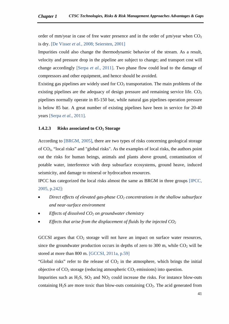
Figure 1.10: Schematic risk profile for a storage project [GCCSI, 2011a] ................................. 42
Figure 1.11: Scope of policy landscapes related to CTSC [GCCSI, 2011a] ............................... 43
Figure 1.12: Components of Risk [Dulac, 2007] ........................................................................ 47
Figure 1.13: Risk Analysis, Risk Assessment and Risk Management process (adapted from [Koivisto et al., 2009]) ................................................................................................................ 48
Figure 1.14: The domino theory [Hollnagel, 2004, p.49] ........................................................... 49
Figure 1.15: Swiss Cheese Model [Reason, 2000]...................................................................... 50
Figure 1.16: Model of a sociotechnical system [Samadi & Garbolino, 2011] ............................ 59
Figure 2.1: Dynamic modeling process ...................................................................................... 68
Figure 2.2: Improved dynamic modeling process ....................................................................... 69
Figure 2.3: Double loop learning in the real world [Sterman, 2000] .......................................... 71
Figure 2.4: An example of stock-flow-feedback loop structure [Dulac et al., 2007] ................. 72
10
Figure 2.5: An example of negative feedback loop [Radzicki & Taylor, 1997] ......................... 72
Figure 2.6: Exogenous and Endogenous perceptions versus the corresponding reality [Richardson, 2011] ...................................................................................................................... 74
Figure 2.7: General steps of dynamic risk analysis for an industrial plant [Garbolino et al., 2010] ........................................................................................................................................... 77
Figure 2.8: Global CO2 atmospheric concentrations and temperature [GCCSI, 2011a] ............. 80
Figure 2.9: The circulation of water in the hydrologic system [Hamblin & Christiansen, 2004] 81
Figure 2.10: The tectonic system [Hamblin & Christiansen, 2004] ............................................ 81
Figure 2.11: Summary of CO2 Storage Life Cycle Phases and Milestones [CCP, 2010] ........... 83
Figure 2.12: Evolution of safety management approaches (translated from [Cambon, 2007]) .. 86
Figure 2.13: Evolution of safety management approaches, an improved proposition ................ 87
Figure 2.14: The sociotechnical system involved in risk management [Rasmussen & Svedung, 2000] ........................................................................................................................................... 88
Figure 2.15: Model of sociotechnical system control [Leveson, 2009] ...................................... 89
Figure 2.16: A standard control loop [Leveson, 2009] ............................................................... 90
Figure 2.17: Example of a control structure relevant to an accident analysis (Citichem) [Leveson, 2009] .......................................................................................................................... 93
Figure 3.1: Proposed methodology steps .................................................................................... 99
Figure 3.2: Methodology of modeling CTSC projects safety control structure ........................ 107
Figure 3.3: Feedback network affecting the risk of not obtaining the required permits ........... 113
Figure 3.4: Feedback network affecting the risk of technology scale-up problems .................. 116
Figure 3.5: Feedback network affecting the risk of public opposition ...................................... 118
Figure 3.6: Evolution of risks and knowledge during CTSC project life cycle [Koornneef et al., 2012] ......................................................................................................................................... 121
Figure 3.7: Feedback network affecting the risk of model and data issues ............................... 122
Figure 3.8: Feedback network affecting the risk of financial resource shortage....................... 124
Figure 3.9: Interconnections of major risks affecting CTSC projects progress ........................ 126
Figure 3.10: Overall feedback network of the risks presented in section 3.2 ........................... 127
11
Figure 3.11: Overall feedback network of the risks, examples of loops ................................... 128
Figure 4.1: Location of Barendrecht in the Netherlands [Zoekplaats, 2010] ............................ 135
Figure 4.2: Barendrecht safety control structure, initial model ................................................. 138
Figure 4.3: Barendrecht safety control structure, improved model ........................................... 140
Figure 4.4: Lacq safety control structure, initial model ............................................................ 143
Figure 4.5: Location of Weyburn CO2 storage field [Verdon, 2012] ........................................ 144
Figure 4.6: Weyburn safety control structure, rough model based on [CCP, 2012] ................. 146
Figure 4.7: Interconnections of major risks affecting Barendrecht project progress ................ 151
Figure 4.8: Interconnections of major risks affecting Barendrecht project progress, modified according to lessons learned...................................................................................................... 152
Figure 4.9: Interconnections of major risks affecting Lacq project progress ............................ 153
Figure 4.10: Interconnections of major risks affecting Weyburn project progress ................... 155
Figure 4.11: Model of a CTSC Project SWOT Analysis .......................................................... 161
Figure 4.12: SWOT Analysis, Barendrecht Project .................................................................. 162
Figure 4.13: SWOT Analysis, Lacq Project .............................................................................. 163
Figure 4.14: SWOT Analysis, Weyburn Project ....................................................................... 163
Figure 4.15: Proposed Safety Control Structure for CTSC projects ......................................... 165
Figure 5.1: Example of extreme risks identified by [GCCSI, 2009a] ....................................... 175
Figure 5.2: Risk Matrix used by [GCCSI, 2009a] .................................................................... 176
Figure 5.3: Integrated CTSC Risk Management methodology proposed by [Kerlero de Rosbo, 2009] ......................................................................................................................................... 177
Figure 5.4: Functions of a scorecard [Fernandez, 2010] ........................................................... 182
12
List of Tables
Table 1.1: Definition of CTSC project phases [GCCSI, 2011a] ................................................. 26
Table 1.2: Storage capacity of different reservoirs [IPCC, 2005] ............................................... 36
Table 1.3: Occupational exposure standards for CO2 [IPCC, 2005] ........................................... 37
Table 1.4: Maximum and recommended level of impurities in CO2 from a health and safety point of view [De Visser et al., 2008] ......................................................................................... 40
Table 1.5: Major risks affecting the very first phases of the project ........................................... 46
Table 1.6: Available Risk Assessment methodologies for CO2 storage [Condor et al., 2011] ... 55
Table 2.1: Classic Rationalism Approach vs. Systemic Approach (translated from [Durand, 2010; Le Moigne, 2006]) ............................................................................................................ 65
Table 3.1: Overview of risks affecting CTSC project progress ................................................ 100
Table 3.2: Risks associated to CTSC and affected project phases ............................................ 101
Table 3.3: Nature of CTSC risks and their consequences ......................................................... 104
Table 3.4: Major risks affecting the very first phases of the project ......................................... 106
Table 3.5: Summary of first example, risk of not obtaining the required permits .................... 114
Table 3.6: Summary of second example, risk of technology scale-up problems ...................... 117
Table 3.7: Summary of third example, risk of public opposition.............................................. 119
Table 3.8: Summary of fourth example, risk of model and data issues .................................... 123
Table 3.9: Summary of fifth example, risk of financial resource shortage ............................... 125
Table 4.1: Comparison of case studies context ......................................................................... 147
Table 4.2: Comparison of risks associated to case studies ........................................................ 149
Table 4.3: Principal Inadequate Control Actions leading to Barendrecht project failure ......... 152
Table 4.4: Principal (Potential) Inadequate Control Actions leading to Lacq project delay or failure ........................................................................................................................................ 154
Table 4.5: Principal (Potential) Inadequate Control Actions leading to Weyburn project delay or failure ........................................................................................................................................ 157

13
Introduction: Context & Thesis Objectives
Introduction: Context & Thesis Objectives
14
CTSC chair, financial supporter of the thesis
The current thesis has been funded by CTSC chair, which is a MINES ParisTech
research program on Capture, Transport and Storage of CO2 (CTSC). The chair covers
eight main research areas including: CO2 capture and capture energy efficiency, CO2
Transport networks and pooled infrastructures, Risks related to CO2 geological storage,
Local and global social perception of carbon storage, Carbon economy and CTSC,
Innovation and large scale diffusion of CTSC technologies, Regional scale impact
assessment and Demonstration programs. Several universities, research centers,
companies and local authority representatives are engaged in CTSC chair program. In
MINES ParisTech, Crisis and Risk research Center (CRC), Center of Energy and
Process (CEP), Center of Geoscience and CERNA (Center of Industrial Economics) are
involved. Several departments of Le Havre university, Le Havre local authorities,
BRGM (Bureau de Recherches Géologiques et Minières), Total, Lafarge, GDF Suez,
EdF and Air Liquide are other partners of the chair [CTSC chair].
Context
Climate change has been a major concern of societies for several years. Global risks
have been categorized in five groups, including economic, environmental, geopolitical,
societal and technological in the latest report of World Economic Forum (WEF) [WEF,
2012]. Climate change is pointed out in two of these categories: environmental and
technological, termed as “Failure of climate change adaptation” and “Unintended
consequences of climate change mitigation” respectively. WEF raises a question
whether our current “safeguards” are appropriate to manage emerging risks which are
inherently present in our complex world; and believes that stakeholders brainstorming is
essential for emerging risks management. Global risks from WEF point of view are
available in Appendixes 1 and 2.
Capture, Transport and Storage of CO2 (CTSC) is one of the technologies planned to
contribute to industrial CO2 emissions and climate change mitigation. CTSC consists of
a chain of processes to collect or capture a CO2 gas stream, transport the CO2 to a
storage location and inject it into that location. The most significant source of CO2
emissions is the combustion of fossil fuels such as coal, oil and gas in power plants,
Introduction: Context & Thesis Objectives
15
automobiles and industrial facilities. A number of specialized industrial production
processes and product uses such as mineral production (cement, lime, etc.), metal
production (iron and steel, aluminum, etc.) and the use of petroleum-based products can
also lead to CO2 emissions [EPA, 2010].
CTSC is currently a constituent of global energy policy, although there are still lots of
uncertainties regarding CTSC contribution and development.
CTSC is considered as a low carbon technology along with renewable energies, nuclear,
increasing energy efficiency and fuel switching. The target is to halve the current CO2
emissions by 2050 [GCCSI, 2011a]. International Energy Agency (IEA) proposes that
CTSC will reduce 19% of CO2 emissions by 2050 [IEA, 2010]. CTSC is concerned
with not only climate change and energy policies, but also industry and innovation
policies [GCCSI, 2011a].
While United Nations Framework Convention on Climate Change (UNFCCC) has
emphasized on the importance and urgency of climate change concerns [UNFCCC,
2012], national policies seem to deal with several uncertainties. Canada’s withdrawal
from Kyoto protocol just after the last climate change conference in Durban (November
28-December 11, 2011) is an example of uncertain policies.
Perceptions of stakeholders on the effectiveness of CTSC are different. Although most
of governments and industries intend to invest on the technology, others such as local
communities and NGOs are worried about long term risks and reliability of CO2
storage. CO2 leakage is the most significant concern of these groups since it could lead
to risks for human beings, animals and plants as well as potable water networks.
Risk Assessment and Management are essential parts of CTSC development in order to
provide answers for the uncertainties and assure the control of well-understood parts of
CTSC processes.
Several studies have been carried out on risk assessment of Capture, Transport and
Storage technologies. Risks of CO2 Capture and Transport are assumed to be well-
understood. Therefore, classical methods have been usually applied for analyzing risks
of Capture and Transport subsystems. However, CO2 storage is known as a “non-
engineered” part of the process, dealing with various uncertainties [Koornneef et al.,
2012]. Consequently, most of available risk assessment studies are focused on CO2
storage technical aspects of risk.
Introduction: Context & Thesis Objectives
16
What is neglected in most of available approaches is that CTSC is a complex
sociotechnical system for which risks could not be analyzed individually, without taking
the whole context into account. Complex system is a system composed of many parts
that interact with and adapt each other. In most cases, the behavior of such systems
cannot be adequately understood by only studying their component parts. This is
because the behavior of such systems arises through the interactions among those parts
[IRGC, 2010]. A sociotechnical system is a one consists of a technical part which is in
interaction with a social part.
Risks associated to CTSC are not limited to technical risks. Along with technical
challenges, CTSC is faced to uncertainties concerning development up to commercial
scales. At the present time, seventy four large scale integrated projects are identified in
the world. Only fourteen projects are in construction or operation phase [GCCSI,
2011a]. A number of projects have been cancelled or delayed for various reasons.
Therefore, a major question about CTSC at the current scale of development is what are
the factors explaining the success or failure of CTSC projects in different contexts?
In order to answer this question, a systemic risk management framework is proposed
based on the concepts of System Dynamics and STAMP (Systems-Theoretic Accident
Model and Processes), developed at Complex Systems Research Laboratory of
Massachusetts Institute of Technology.
Aside from sociotechnical complexity of CTSC system, the idea comes from systemic
and dynamic characteristics of risk. Systems are regularly adapting themselves to
perturbations. Nevertheless, positive feedbacks lead to system destabilization by
amplifying the perturbations. So, it is important to identify feedback dynamics involved
in the system in order to better anticipate when risks might emerge or be amplified
[IRGC, 2010]. In this thesis, systemic modeling is proposed as a decision making
support, which provides the grounds of thinking about the components of a potentially
successful CTSC project. Each stakeholder is assumed as a “controller”, who is
responsible for maintaining safety constraints. Safety control structures are developed
for several case studies to formalize the relations of stakeholders in maintaining safety
constraints.
Introduction: Context & Thesis Objectives
17
Thesis Objectives
The initial objective of the thesis was to develop an integrated risk analysis
methodology. The purpose was to cover health and safety risks for the operators and
local population as well as environmental risks. System dynamics was planned to be
applied for modeling interactions of technical system, operators and decision makers.
Following steps were anticipated for the work:
- Studying lessons learned from CTSC incidents and accidents
- Identifying the actors of CTSC chain
- Modeling the technical system and its connections with the human and
organizational parts
- Dynamic analysis of risks
- Defining deviation scenarios
- Consequence analysis of scenarios
- Providing recommendations
The models were planned to be verified in a CTSC pilot plant.
The research question was progressively formulated as studying the performance of
CTSC safety control system.
In the course of study, the objective and research question were modified for several
reasons. The main reasons include:
1. CTSC integrated chain is an emerging technology for which few lessons learned are
available. Publically available information on CTSC is restricted due to
confidentiality issues. Therefore, gathering information on operational aspects of risk
was a challenge.
2. Feedback loop is an essential concept of system dynamics which has to be integrated
in system dynamics models. The models of technical system confirmed that feedback
loops appear only when we consider interconnections of system variables and control
variables. Studying such interconnections requires a great amount of data, which are
not available for CTSC.
3. Discussions with experts of the domain led us to the conclusion that the most
significant question in terms of integrated CTSC risk analysis is not the performance
of CTSC safety control system from technical point of view. The actual concern is
whether CTSC projects will be developed up to commercial scales.
Introduction: Context & Thesis Objectives
18
Based on these facts, the research question formulation was modified in the final year of
the thesis. Effectiveness of safety control structure is still in question. However, a
broader definition of safety is taken into account. Safety is defined as the absence of
losses due to an undesired event. “Losses” in this definition include human losses,
mission or goal losses, equipment or material losses and environmental losses [Dulac,
2007, p.31]. The thesis is focused on mission or goal losses. Other kinds of failures do
have impacts on mission losses.
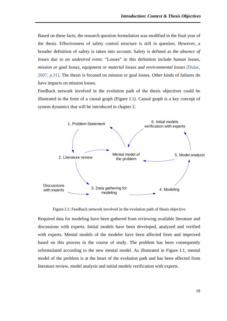
Feedback network involved in the evolution path of the thesis objectives could be
illustrated in the form of a causal graph (Figure I.1). Causal graph is a key concept of
system dynamics that will be introduced in chapter 2.
1. Problem Statement
2. Literature review
3. Data gathering formodeling
Mental model ofthe problem
4. Modeling
5. Model analysis
6. Initial modelsverification with experts
Discussionswith experts
Figure I.1: Feedback network involved in the evolution path of thesis objective
Required data for modeling have been gathered from reviewing available literature and
discussions with experts. Initial models have been developed, analyzed and verified
with experts. Mental models of the modeler have been affected from and improved
based on this process in the course of study. The problem has been consequently
reformulated according to the new mental model. As illustrated in Figure I.1, mental
model of the problem is at the heart of the evolution path and has been affected from
literature review, model analysis and initial models verification with experts.
Introduction: Context & Thesis Objectives
19
Manuscript outline
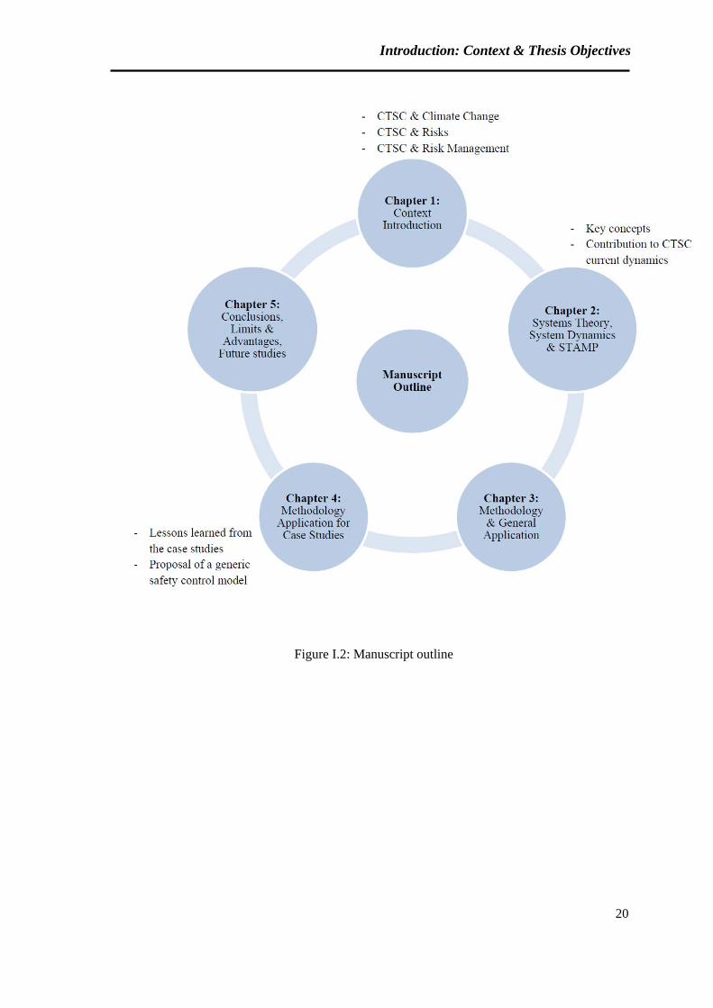
The manuscript contains five chapters.
CTSC contribution to climate change and an overview of CTSC projects current status
are presented in chapter 1. Capture, Transport and Storage processes and associated
risks are then reviewed. Different aspects of risk related to CTSC whole chain are
introduced here, including Technical, HSE (Health, Safety and Environment),
Policy/Strategy, Legal, Organizational/Human, Financial/Economic, Social and risks
concerning the Project.
Afterwards, principal notions of risk management as well as traditional and latest risk
management approaches are reviewed.
At the final section of chapter 1, available risk management methods for Capture,
Transport and Storage subsystems and CTSC whole chain are presented. And we wrap
up with the necessity of developing a systemic risk management framework for CTSC.
Chapter 2 deals with how system dynamics and systemic approaches could contribute to
CTSC risk management. The chapter begins with the introduction of systems theory and
system dynamics. After reviewing application fields of system dynamics, dynamics
involved in the current CTSC context are presented. Key concepts and examples of
STAMP are provided at the end of the chapter, where we explain how systemic
approaches, and particularly STAMP, can be applied for studying CTSC dynamics.
Chapter 3 is devoted to the proposed methodology. The methodology steps are detailed
in this chapter. Main risks involved in CTSC projects are reviewed and modeled.
Application of the methodology for some case studies is presented in chapter 4. Further
discussions and comparison of case studies are provided in this chapter. The aim is to
propose an improved safety control structure for CTSC projects according to the
analysis of the case studies. SWOT (Strengths, Weaknesses, Opportunities and Threats)
matrices are also presented to give an overall view of positive and negative aspects of
the case studies.
Finally, some overall conclusions are presented in Chapter 5. Advantages and
limitations of the methodology and areas for further research are also discussed in this
final chapter.
Figure I.2 summarizes the manuscript outline.
Introduction: Context & Thesis Objectives
20
Figure I.2: Manuscript outline

21
Chapter 1: CTSC Technologies, Risks & Risk Management Approaches Advantages & Gaps
Chapter 1 CTSC Technologies, Risks & Risk Management Approaches Advantages & Gaps
22
The purpose of chapter 1 is to introduce CTSC (Capture, Transport and Storage of
CO2), the risks associated with this innovative technology, and the gaps in available risk
management approaches.
This chapter is divided into six major parts. The first three sections provide an overview
of CTSC technology and its current status in the world, as well as the contribution of
CTSC to climate change.
In the fourth part, a review of risks associated with CTSC subsystems and the whole
chain are presented.
The fifth section focuses on the evolution of risk management approaches. Limitations
of classic methods and the requirement of novel approaches for innovative technologies
are discussed in this part.
In the last section of this chapter, available risk management methods for CTSC are
reviewed and the necessity of developing an integrated approach is discussed.
The following two points shall be taken into consideration:
1. In this report, “CO2 storage” refers to the storage in geological formations
(described in section 1.3.3). Otherwise, the storage system is clearly specified.
2. In this report, “CTSC” is used for the integrated chain of Capture, Transport and
Storage of CO2. In a number of citations, “CCS” is referred to the same integrated
system.
1.1 CTSC and Climate Change
Capture, Transport and Storage of CO2 (CTSC) is one of the contribution options for
mitigating industrial CO2 emissions in the atmosphere. CTSC technology is developing
along with other low carbon technologies such as renewable resources, increasing
energy efficiency, fuel switching and nuclear. The set target is halving the emissions by
2050 (compared to the current amount) [GCCSI, 2011a, p.3]. The current (April 2012)
amount of CO2 in the atmosphere is equal to 394.01 ppm [ESRL, 2012].
Two main scenarios are established for CO2 emissions reduction: Baseline and BLUE
Map. The assumption in Baseline scenario is that no new energy and climate policy are
introduced by governments. However, in BLUE Map scenario, the objective is to halve
the emissions by 2050 (compared to 2005) by deploying existing and new low carbon
Chapter 1 CTSC Technologies, Risks & Risk Management Approaches Advantages & Gaps
23
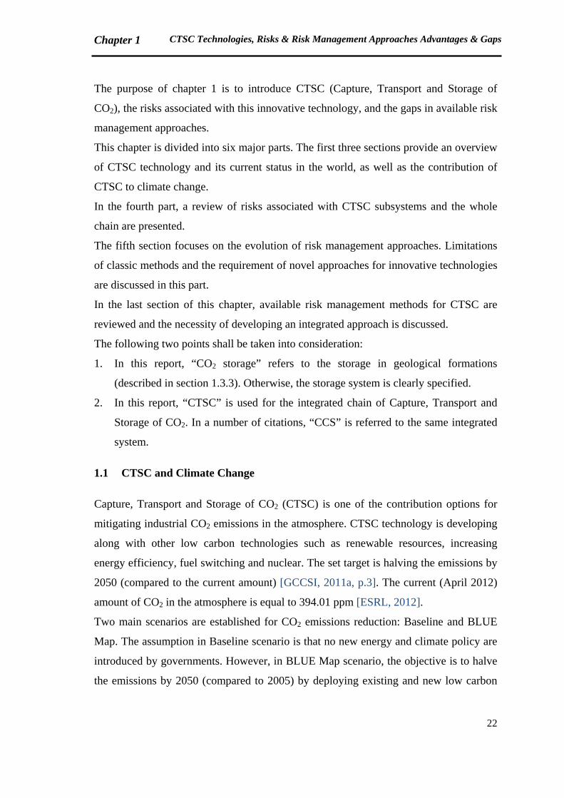
technologies [IEA, 2010]. Key technologies for reducing emissions under BLUE Map
scenario is illustrated in the following figure:
Figure 1.1: Key technologies for reducing CO2 emissions under the BLUE Map scenario [IEA, 2010]
A European Directive has been published in 2009 to propose a regulatory framework
for CTSC (geological storage of CO2) in order to remove the legal barriers and ensure
the environmentally safe development of the technology. The Directive shall not apply
to geological storage of CO2, with a total intended storage below 100 kilotonnes,
undertaken for research, development or testing of new products and processes.
According to the preliminary estimations, 7 million tonnes of CO2 could be stored by
2020, and up to 160 million tonnes by 2030. [EU Directive, 2009]
There is not a mutual agreement about the necessity and effectiveness of CTSC in
global energy policies. Non-Governmental Organizations (NGOs) are major opponents
of CTSC development. An example is Greenpeace, which is an international
environmental NGO. Greenpeace believes that CTSC is not ready to save the climate in
time. According to the United Nations Development Program (UNDP), CTSC will
arrive on the battlefield far too late to help the world avoid dangerous climate change
[UNDP, 2007, p.145]. Energy waste, risk of CO2 leakage, expensiveness and liability
risks are some other points noticed by Greenpeace for supporting the idea of conceiving
CTSC as “False Hope”. Greenpeace believes that renewable energy and improving
energy efficiency are safe and cost-effective for the climate change problem. The results
of a Carbon Capture Journal survey (in 2008) have been cited by Greenpeace. The
Chapter 1 CTSC Technologies, Risks & Risk Management Approaches Advantages & Gaps
24
survey of one thousand (1000) climate decision makers and influencers shows that there
is a substantial doubt in the ability of CCS to deliver. Just 34% were confident that
retrofitting ‘clean coal technology’ to existing power plants could reduce CO2
emissions over the next 25 years without unacceptable side effects, and only 36% were
confident in its ability to deliver low-carbon energy from new power stations.
Greenpeace adds that six thousand (6000) CTSC projects are required, with the
injection rate of 1 million tonnes per year each, to mitigate climate change effects by
2050. [Rochon et al., 2008]
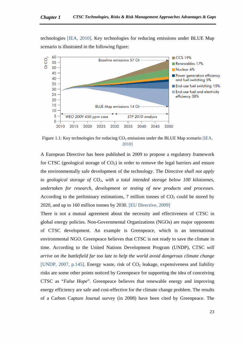
CTSC refers to the chain of processes used to collect or capture a CO2 gas stream,
transport the CO2 to a storage location and inject it into that location. An overall view of
CTSC possible systems is illustrated in the following figure:
Figure 1.2: Possible CTSC systems [IPCC, 2005]
The most significant source of CO2 emissions is the combustion of fossil fuels such as
coal, oil and gas in power plants, automobiles, industrial facilities, etc. A number of
specialized industrial production processes and product uses such as mineral production
(cement, lime, etc.), metal production (iron and steel, aluminum, etc.) and the use of
Chapter 1 CTSC Technologies, Risks & Risk Management Approaches Advantages & Gaps
25
petroleum-based products can also lead to CO2 emissions [EPA, 2010]. A summary of
the most significant sources of CO2 emissions is available in Appendix 3.
1.2 CTSC projects current status in the world
So far, seventy four Large Scale Integrated Projects (LSIP) are identified all around the
world. Global CCS Institute (GCCSI) defines LSIP as the projects which involve all the
three subsystems (Capture, Transport and Storage), with the storage capacity of not less
than 800,000 tonnes/year for a coal-based power plant and not less than 400,000
tonnes/year for other industrial plants. These figures are related to GCCSI survey
conducted in May-August 2011 [GCCSI, 2011a].
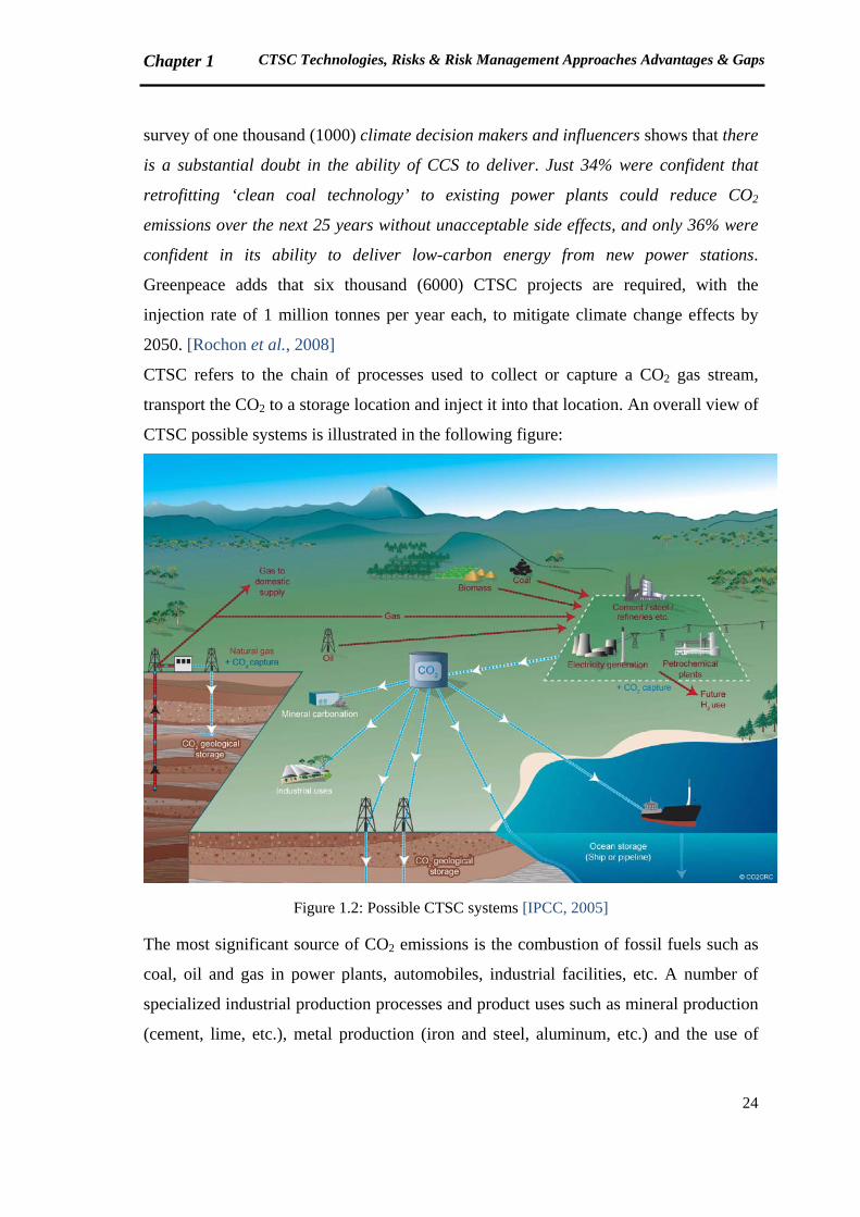
The current status of LSIP CTSC projects is summarized in the following figure:
Figure 1.3: LSIP CTSC projects by region and project phase [GCCSI, 2011a]
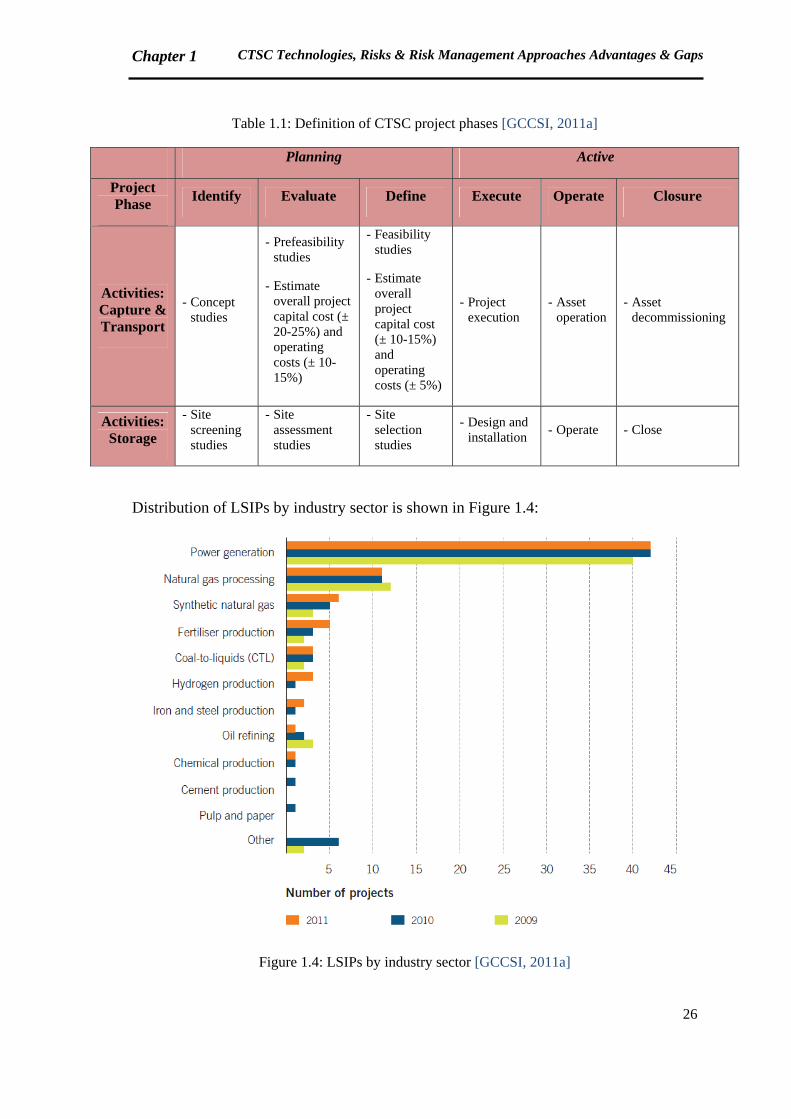
The activities related to the project phases, presented in Figure 1.3, are defined in Table
1.1 (a closure phase is added at the end).
Chapter 1 CTSC Technologies, Risks & Risk Management Approaches Advantages & Gaps
26
Table 1.1: Definition of CTSC project phases [GCCSI, 2011a]
Planning Active
Project Phase
Identify Evaluate Define Execute Operate Closure
Activities: Capture & Transport
- Concept studies
- Prefeasibility studies
- Estimate overall project capital cost (± 20-25%) and operating costs (± 10-15%)
- Feasibility studies
- Estimate overall project capital cost (± 10-15%) and operating costs (± 5%)
- Project execution
- Asset operation
- Asset decommissioning
Activities: Storage
- Site screening studies
- Site assessment studies
- Site selection studies
- Design and installation
- Operate - Close
Distribution of LSIPs by industry sector is shown in Figure 1.4:
Figure 1.4: LSIPs by industry sector [GCCSI, 2011a]
Chapter 1 CTSC Technologies, Risks & Risk Management Approaches Advantages & Gaps
27
Eleven CTSC projects (LSIP) have been cancelled or made on-hold between 2010 and
2011. Being uneconomic is the reason often cited for these cancellations. [GCCSI,
2011a, p.viii]
Following this brief presentation of CTSC systems current status, a general introduction
of Capture, Transport and Storage technologies is provided in the next section.
1.3 CTSC Technology: An overall introduction
In this section, different processes of CO2 Capture, Transport and Storage are presented.
1.3.1 CO2 Capture
At present, large scale CO2 separation units are available in natural gas treatment and
ammonia production plants. However, the major purpose of such CO2 separation is to
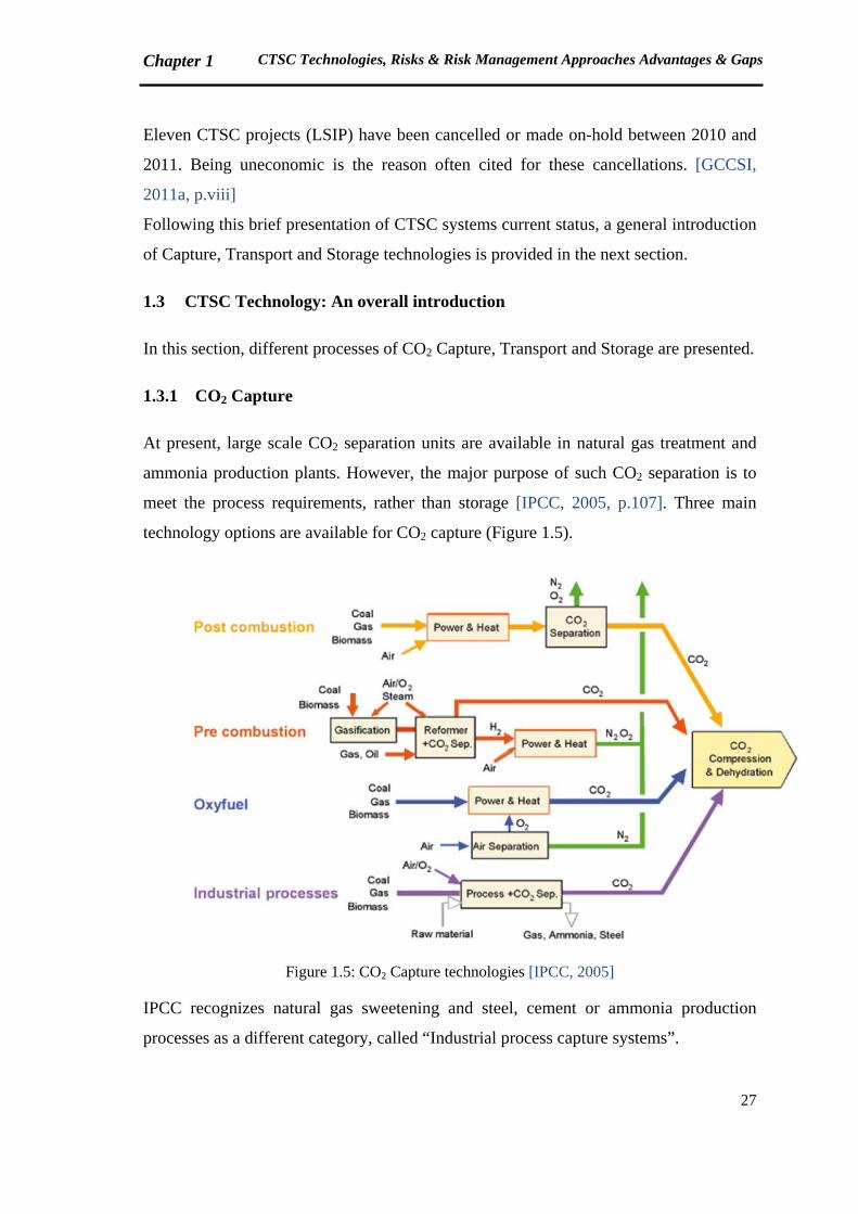
meet the process requirements, rather than storage [IPCC, 2005, p.107]. Three main
technology options are available for CO2 capture (Figure 1.5).
Figure 1.5: CO2 Capture technologies [IPCC, 2005]
IPCC recognizes natural gas sweetening and steel, cement or ammonia production
processes as a different category, called “Industrial process capture systems”.
Chapter 1 CTSC Technologies, Risks & Risk Management Approaches Advantages & Gaps
28
In subsequent paragraphs, we will review the major characteristics of CO2 Capture
technologies [IPCC, 2005; Lecomte et al., 2010]:
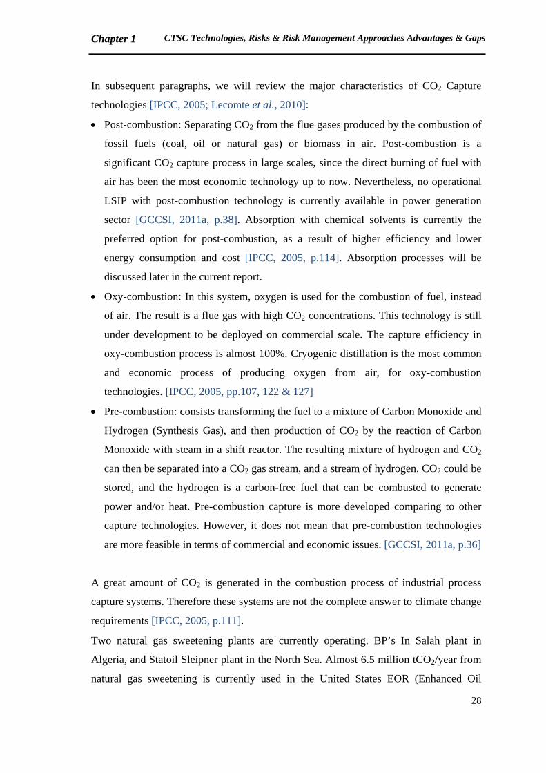
Post-combustion: Separating CO2 from the flue gases produced by the combustion of
fossil fuels (coal, oil or natural gas) or biomass in air. Post-combustion is a
significant CO2 capture process in large scales, since the direct burning of fuel with
air has been the most economic technology up to now. Nevertheless, no operational
LSIP with post-combustion technology is currently available in power generation
sector [GCCSI, 2011a, p.38]. Absorption with chemical solvents is currently the
preferred option for post-combustion, as a result of higher efficiency and lower
energy consumption and cost [IPCC, 2005, p.114]. Absorption processes will be
discussed later in the current report.
Oxy-combustion: In this system, oxygen is used for the combustion of fuel, instead
of air. The result is a flue gas with high CO2 concentrations. This technology is still
under development to be deployed on commercial scale. The capture efficiency in
oxy-combustion process is almost 100%. Cryogenic distillation is the most common
and economic process of producing oxygen from air, for oxy-combustion
technologies. [IPCC, 2005, pp.107, 122 & 127]
Pre-combustion: consists transforming the fuel to a mixture of Carbon Monoxide and
Hydrogen (Synthesis Gas), and then production of CO2 by the reaction of Carbon
Monoxide with steam in a shift reactor. The resulting mixture of hydrogen and CO2
can then be separated into a CO2 gas stream, and a stream of hydrogen. CO2 could be
stored, and the hydrogen is a carbon-free fuel that can be combusted to generate
power and/or heat. Pre-combustion capture is more developed comparing to other
capture technologies. However, it does not mean that pre-combustion technologies
are more feasible in terms of commercial and economic issues. [GCCSI, 2011a, p.36]
A great amount of CO2 is generated in the combustion process of industrial process
capture systems. Therefore these systems are not the complete answer to climate change
requirements [IPCC, 2005, p.111].
Two natural gas sweetening plants are currently operating. BP’s In Salah plant in
Algeria, and Statoil Sleipner plant in the North Sea. Almost 6.5 million tCO2/year from
natural gas sweetening is currently used in the United States EOR (Enhanced Oil
Chapter 1 CTSC Technologies, Risks & Risk Management Approaches Advantages & Gaps
29
Recovery) projects. The most familiar natural gas sweetening method is using
alkanolamines (such as MEA, DEA, MDEA). For high CO2 concentrations, membrane
systems are more economical [IPCC, 2005, p.112].
Details of steel, cement and ammonia production capture systems are not discussed in
the present report.
Several technologies could be used to separate CO2 in each of the above-mentioned
systems (Post-combustion, Oxy-combustion, Pre-combustion). The major separation
methods are as following:
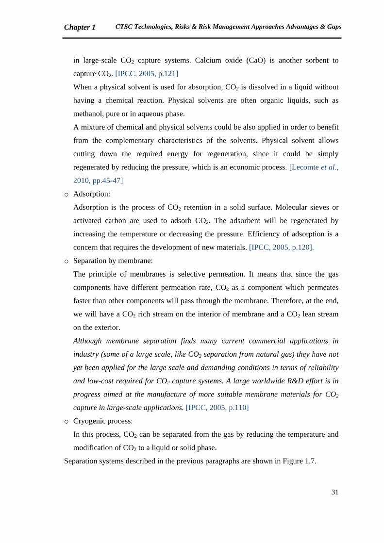
o Absorption by chemical or physical solvents, or a mixture of both:
In the case of chemical absorption, CO2 will be absorbed from the flue gas, while
contacting a chemical solvent in an absorption tower. The absorber temperature is
typically between 40 and 60 °C. In the second phase of the process, CO2 will be
extracted from the rich solvent (rich in CO2) by modification of pressure and
temperature conditions. The regeneration is carried out at high temperatures (100-
140 °C) and low pressure (not more than atmospheric pressure). Regenerated solvent
of the second phase will be recycled to the absorption tower; while sour gas,
containing CO2, will be transported for storage or utilization. Recovered CO2 will be
typically at 0.5 bar and 99.9 vol% (figures from [IPCC, 2005, pp.115 & 116]). A
typical schematic of a commercial absorption system is illustrated in Figure 1.6. The
most common chemical solvents used in absorption process are aqueous solvents
containing an alkanolamine (e.g. MEA, DEA, MDEA).
Chapter 1 CTSC Technologies, Risks & Risk Management Approaches Advantages & Gaps
30
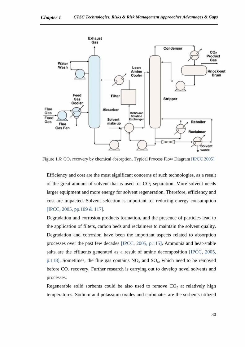
Figure 1.6: CO2 recovery by chemical absorption, Typical Process Flow Diagram [IPCC 2005]
Efficiency and cost are the most significant concerns of such technologies, as a result
of the great amount of solvent that is used for CO2 separation. More solvent needs
larger equipment and more energy for solvent regeneration. Therefore, efficiency and
cost are impacted. Solvent selection is important for reducing energy consumption
[IPCC, 2005, pp.109 & 117].
Degradation and corrosion products formation, and the presence of particles lead to
the application of filters, carbon beds and reclaimers to maintain the solvent quality.
Degradation and corrosion have been the important aspects related to absorption
processes over the past few decades [IPCC, 2005, p.115]. Ammonia and heat-stable
salts are the effluents generated as a result of amine decomposition [IPCC, 2005,
p.118]. Sometimes, the flue gas contains NOx and SOx, which need to be removed
before CO2 recovery. Further research is carrying out to develop novel solvents and
processes.
Regenerable solid sorbents could be also used to remove CO2 at relatively high
temperatures. Sodium and potassium oxides and carbonates are the sorbents utilized
Chapter 1 CTSC Technologies, Risks & Risk Management Approaches Advantages & Gaps
31
in large-scale CO2 capture systems. Calcium oxide (CaO) is another sorbent to
capture CO2. [IPCC, 2005, p.121]
When a physical solvent is used for absorption, CO2 is dissolved in a liquid without
having a chemical reaction. Physical solvents are often organic liquids, such as
methanol, pure or in aqueous phase.
A mixture of chemical and physical solvents could be also applied in order to benefit
from the complementary characteristics of the solvents. Physical solvent allows
cutting down the required energy for regeneration, since it could be simply
regenerated by reducing the pressure, which is an economic process. [Lecomte et al.,
2010, pp.45-47]
o Adsorption:
Adsorption is the process of CO2 retention in a solid surface. Molecular sieves or
activated carbon are used to adsorb CO2. The adsorbent will be regenerated by
increasing the temperature or decreasing the pressure. Efficiency of adsorption is a
concern that requires the development of new materials. [IPCC, 2005, p.120].
o Separation by membrane:
The principle of membranes is selective permeation. It means that since the gas
components have different permeation rate, CO2 as a component which permeates
faster than other components will pass through the membrane. Therefore, at the end,
we will have a CO2 rich stream on the interior of membrane and a CO2 lean stream
on the exterior.
Although membrane separation finds many current commercial applications in
industry (some of a large scale, like CO2 separation from natural gas) they have not
yet been applied for the large scale and demanding conditions in terms of reliability
and low-cost required for CO2 capture systems. A large worldwide R&D effort is in
progress aimed at the manufacture of more suitable membrane materials for CO2
capture in large-scale applications. [IPCC, 2005, p.110]
o Cryogenic process:
In this process, CO2 can be separated from the gas by reducing the temperature and
modification of CO2 to a liquid or solid phase.
Separation systems described in the previous paragraphs are shown in Figure 1.7.
Chapter 1 CTSC Technologies, Risks & Risk Management Approaches Advantages & Gaps
32
Figure 1.7: General schemes of CO2 Capture main separation processes [IPCC, 2005]
After capturing, CO2 will be transported to the storage location. Available CO2
transportation modes are summarized in the next section.
1.3.2 CO2 Transport
CO2 can be transported to the storage location either by onshore/offshore pipelines, by
tankers or ships. CO2 transport is not a new technology, particularly in North America.
According to GCCSI (2011a), almost 6000 km of CO2 pipelines are currently in service.
This network transports approximately 50 Mtpa of CO2 and has been developed over
the past 40 years. The majority of this transport network is in the United States, where
CO2 is mostly transported from natural resources to oilfields as part of CO2 Enhanced
Oil Recovery (EOR). Long distance CO2 pipelines are not available in Europe, except
Turkey. Recently, some networks have started to operate in the North Sea and the
Netherlands [Gale & Davison, 2004; Serpa et al., 2011]. CO2 transportation in the US is
in the industrial scale. Some industries believe that the difference between the US and
Europe is due to the more populated areas, more complicated process of obtaining
permits, and social acceptance issues in Europe [Jallais, 2011].

Chapter 1 CTSC Technologies, Risks & Risk Management Approaches Advantages & Gaps
33
CO2 is in supercritical state while transporting with a pressure of more than 74 bar
(being in supercritical state means that CO2 is at a temperature and pressure above its
critical point). Critical temperature and pressure of CO2 are 31.1°C and 73.9 bar
respectively (Figure 1.8). When CO2 is in supercritical state, it will have the viscosity of
a gas, but the density of a liquid. CO2 transportation by pipeline on the liquid state (10
bar and -40°C) is still in the research phase. For long distances, CO2 will be transported
by ship in liquid phase (20 bar and -20°C) [Lecomte et al., 2010]. Road and rail tankers
are the other technically feasible options. These systems transport CO2 at -20°C and 20
bar. However, they are uneconomical compared to pipelines and ships, except on a very
small scale, and are unlikely to be relevant to large-scale CTSC [IPCC, 2005].
Figure 1.8: CO2 phase diagram [IPCC, 2005]
It has been estimated that to support the 3400 industrial scale CCS projects by 2050 in
the IEA BLUE map scenario, over 200,000 km of pipeline would need to be constructed,
at a cost of US$2.5 to 3 trillion. The estimation of CO2 Europipe consortium for Europe
is 22,000 km by 2050 [GCCSI, 2011a, pp.47-49].
The succeeding phase of CTSC process could be either the storage of CO2 or utilization
of CO2 in the industries. This concept will be discussed in the following section.
Chapter 1 CTSC Technologies, Risks & Risk Management Approaches Advantages & Gaps
34
1.3.3 CO2 Storage and utilization
Several methods are available to store or use the captured and transported CO2.
Principal methods of CO2 storage are as follows [IPCC, 2005]:
Geological storage:
CO2 can be stored in various geological formations. The most significant options are
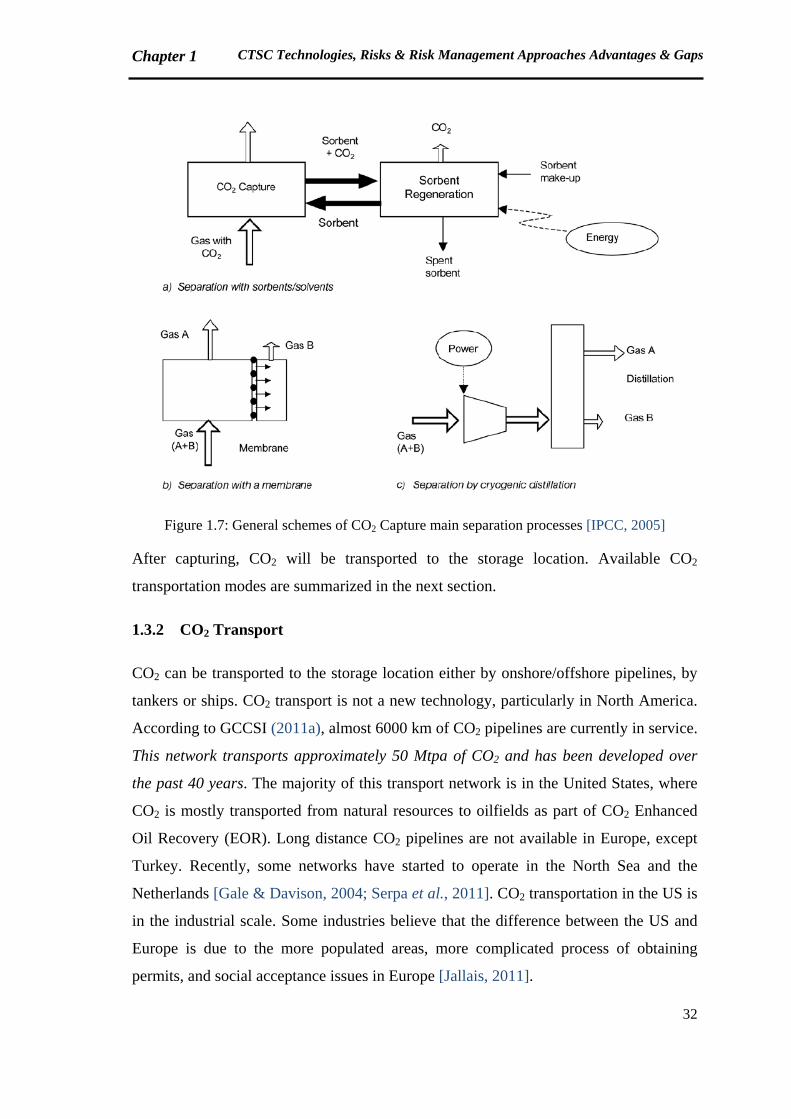
illustrated in Figure 1.9:
Figure 1.9: CO2 geological storage options [GCCSI, 2011a]
As noted before, transported CO2 to the storage location is in supercritical phase.
When CO2 is injected in a geological formation, its density will increase with depth
until about 800m or more. Therefore, the injected CO2 is in a dense supercritical
state.
Ocean storage:
In this case, CO2 will be compressed, transported by a ship and directly injected into
the ocean (in liquid phase) at a depth greater than 1000 meter, where CO2 would be
mostly isolated from the atmosphere for centuries. Ocean storage will have critical
Chapter 1 CTSC Technologies, Risks & Risk Management Approaches Advantages & Gaps
35
effects on the ocean ecosystem and there are still legal restrictions on the
development of this option.
Mineral Carbonation or Mineral Sequestration:
Mineral carbonation is based on the reaction of CO2 with calcium or magnesium
oxide to form insoluble carbonates. Magnesium carbonate (MgCO3) and calcium
carbonate (CaCO3) are the products of such reactions. The carbonates are stable for a
long time and can be used for construction, mine reclamation or disposed of without
the need for monitoring or the concern of potential CO2 leaks that could pose safety
or environmental risks. Mineral carbonation is classified as a CO2 reuse technology
by particular references [GCCSI, 2011b, p.127].
As mentioned at the beginning of the chapter, ocean storage and mineral carbonation
are not in the scope of the current research. The risks of these technologies are
completely different from the geological storage risks.
CO2 reuse is another alternative for reducing CO2 emissions. CO2 reuse is defined as
any practical application of captured CO2 that adds value (such as revenue generation,
or environmental benefit), and which can partially offset the cost of CO2 capture
[GCCSI, 2011b]. Enhanced Oil Recovery (EOR), production of chemicals such as urea,
beverage carbonation, food processing, preservation and packaging, pharmaceutical
processes, horticulture, pulp and paper processing, refrigeration systems, welding
systems, fire extinguishers, and water treatment processes are some examples of the
existing CO2 uses. Enhanced Coal Bed Methane recovery (ECBM), polymer processing,
mineralization and production of liquid fuels (like methanol) are the emerging CO2
utilization processes. [GCCSI, 2011b; IPCC, 2005]
EOR is a well-known reuse option for CO2, particularly in the United States. According
to GCCSI, EOR will remain the dominant form of CO2 reuse in the short and medium
term due to its maturity and large-scale utilization of CO2. GCCSI believes that EOR
plays a significant role in the development of large-scale CTSC projects. [GCCSI,
2011b]
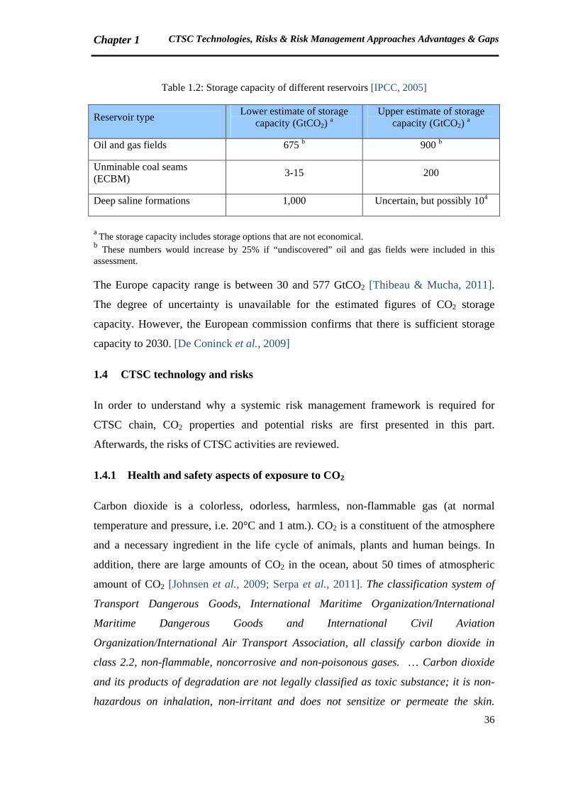
An estimation of CO2 storage capacity has been published in IPCC report (Table 1.2).
Chapter 1 CTSC Technologies, Risks & Risk Management Approaches Advantages & Gaps
36
Table 1.2: Storage capacity of different reservoirs [IPCC, 2005]
Reservoir type Lower estimate of storage
capacity (GtCO2) a
Upper estimate of storage capacity (GtCO2)
a
Oil and gas fields 675 b 900 b
Unminable coal seams (ECBM)
3-15 200
Deep saline formations 1,000 Uncertain, but possibly 104
a The storage capacity includes storage options that are not economical. b These numbers would increase by 25% if “undiscovered” oil and gas fields were included in this assessment.
The Europe capacity range is between 30 and 577 GtCO2 [Thibeau & Mucha, 2011].
The degree of uncertainty is unavailable for the estimated figures of CO2 storage
capacity. However, the European commission confirms that there is sufficient storage
capacity to 2030. [De Coninck et al., 2009]
1.4 CTSC technology and risks
In order to understand why a systemic risk management framework is required for
CTSC chain, CO2 properties and potential risks are first presented in this part.
Afterwards, the risks of CTSC activities are reviewed.
1.4.1 Health and safety aspects of exposure to CO2
Carbon dioxide is a colorless, odorless, harmless, non-flammable gas (at normal
temperature and pressure, i.e. 20°C and 1 atm.). CO2 is a constituent of the atmosphere
and a necessary ingredient in the life cycle of animals, plants and human beings. In
addition, there are large amounts of CO2 in the ocean, about 50 times of atmospheric
amount of CO2 [Johnsen et al., 2009; Serpa et al., 2011]. The classification system of
Transport Dangerous Goods, International Maritime Organization/International
Maritime Dangerous Goods and International Civil Aviation
Organization/International Air Transport Association, all classify carbon dioxide in
class 2.2, non-flammable, noncorrosive and non-poisonous gases. … Carbon dioxide
and its products of degradation are not legally classified as toxic substance; it is non-
hazardous on inhalation, non-irritant and does not sensitize or permeate the skin.

Chapter 1 CTSC Technologies, Risks & Risk Management Approaches Advantages & Gaps
37
However, chronic effects on humans follow from long-term exposure to airborne carbon
dioxide concentrations of between 0.5 and 1% resulting in metabolic acidosis and
increased calcium deposits in soft tissues. The substance is toxic to the cardiovascular
system and upper respiratory tract at concentrations above 3%.
… As an asphyxiate carbon dioxide presents the greatest danger. If atmospheric oxygen
is displaced such that oxygen concentration is 15-16%, signs of asphyxia will be noted.
… Protective equipment and clothing required in the processing industries include full
face-piece respirators to prevent eye contact and appropriate personal protective
clothing to protect the skin from becoming frozen by the liquid. [IPCC, 2005, p.145]
As CO2 is 1.5 times denser than air (CO2 MW=44), there will be a tendency for any
CO2 leaking from pipework or storage to collect in hollows and other low-lying
confined spaces which could create hazardous situations. The hazardous nature of the
release of CO2 is enhanced because the gas is colorless, tasteless and is generally
considered odorless unless present in high concentrations [IPCC, 2005, p.390].
According to the standards, a concentration of 0.5% is acceptable for a continuous
exposure to CO2, while it will be dangerous if the concentration is more than 5%.
Occupational exposure limits for CO2 are summarized in Table 1.3:
Table 1.3: Occupational exposure standards for CO2 [IPCC, 2005]
Time-weighted
average (8 hour/day, 40 hour/week)
Short-term exposure limit (15 minutes)
Immediately dangerous to life and
health
OSHA permissible exposure limit a
5000 ppm (0.5%)
NIOSH recommended exposure limit b
5000 ppm (0.5%) 30,000 ppm (3%) 50,000 (5%) d
ACGIH threshold limit value c
5000 ppm (0.5%)
a OSHA: US Occupational Safety and Health Administration (1986)
b NIOSH: US National Institute of Occupational Safety and Health (1997)
c ACGIH: American Conference of Governmental Industrial Hygienists
d Corrected based on http://www.cdc.gov/niosh/idlh/124389.html, accessed June 19, 2012
A more comprehensive list of exposure limits is available in Appendix 4.
Chapter 1 CTSC Technologies, Risks & Risk Management Approaches Advantages & Gaps
38
According to DNV, incidents related to CO2 could be categorized in three main groups
[Johnsen et al., 2009]:
Fire extinguisher systems: As summarized by US Environmental Protection Agency
(EPA), from 1975 to 2000, a total of 51 carbon dioxide incident records were
located that reported a total of 72 deaths and 145 injuries resulting from accidents
involving the discharge of carbon dioxide from fire extinguishing systems. Prior to
1975, a total of 11 incident records were located that reported a total of 47 deaths
and 7 injuries involving carbon dioxide. Twenty of the 47 deaths occurred in
England prior to 1963; however, the cause of these deaths is unknown. (The oldest
reference of these figures dates back to 1910 [EPA, 2000])
Pipelines: According to the US Office of Pipeline Safety, statistics on pipeline
incidents could be summarized as follows: In the period of 1986-2001, 11 incidents
related to pipeline transport of CO2 are reported with one fatality and two injuries.
According to the statistic log, the fatality was associated with welding work and not
as a direct consequence of pipeline operation. Nine of the incidents were related to
the pipeline (all onshore), whereas the remaining two were located at the pumping
station. In the period of 2002- 2008, 18 incidents related to pipeline transport of CO2
are reported with no fatalities and injuries. Nine of these incidents were solely
related to the onshore pipeline itself, whereas the remaining were related to
incidents at pump/meter station, terminal/tank farm piping and equipment, including
sumps.
Natural outgassing of CO2: Two examples are mentioned in this category of
incidents. Lake Nyos, Cameroon in 1986, with 1700 fatalities within 20 km of the
lake; and Lake Monoun, Cameroon in 1984, killing 37 local residents.
The reader is referred to the DNV report [Johnsen et al., 2009] for more information on
the above-noted incidents. A list of CO2 vessel ruptures until today is also available in
the same report.
1.4.2 CTSC: risks associated to each phase & to CTSC chain
De Coninck et al. believe that the risks of CTSC are difficult to identify, not only
technically but due to the stakeholders different perceptions of risks. Perceptions of
Chapter 1 CTSC Technologies, Risks & Risk Management Approaches Advantages & Gaps
39
energy policy and requirement of low-carbon energy could also affect the perceptions of
CO2 storage risks. [De Coninck et al., 2009]
In this section, we firstly summarize the risks related to each phase. Afterwards, the
risks of CTSC whole system are discussed.
1.4.2.1 Risks associated to CO2 Capture
The most fundamental risks in CO2 capture processes are associated with the vent gas
produced from the capture plant, as well as liquid and solid wastes. The captured CO2
stream may contain impurities which would have practical impacts on CO2 transport
and storage systems and also potential health, safety and environmental impacts. SO2,
NO, H2S, H2, CO, CH4, N2, Ar and O2 are the impurities that will be available in the
CO2 stream, depending on the capture process type. Moisture of CO2 from most capture
processes has to be removed to avoid corrosion and hydrate formation during
transportation [IPCC, 2005, p.141]. Problems of impurities will be readdressed in the
next parts (1.4.2.2 & 1.4.2.3).
The energy required to operate CO2 capture systems reduces the overall efficiency of
power generation or other processes, leading to increased fuel requirements, solid
wastes and environmental impacts relative to the same type of base plant without
capture [IPCC, 2005, p.107].
Another major concern about CO2 capture is the cost of capture technologies [GCCSI,
2011a, p.34]. Several research and development studies are carrying out to find the cost
reduction methods.
IPCC believes that monitoring, risk and legal aspects associated with CO2 capture
systems appear to present no new challenges, as they are all elements of long-standing
health, safety and environmental control practice in industry. [IPCC, 2005, p.107]
CO2 capture and compression processes are listed as gas processing facilities in several
governmental, industrial and finance guidelines. Typical engineering design,
commissioning and start-up activities associated with petrochemical facilities are
applicable to CO2 capture and compression. For example HAZard OPerability
(HAZOP) studies are conducted on a routine basis for new facilities [IPCC, 2005,
p.146].
Chapter 1 CTSC Technologies, Risks & Risk Management Approaches Advantages & Gaps
40
1.4.2.2 Risks associated to CO2 Transport
Risks related to CO2 transportation obviously depend on the transportation mode and on
the local topography, meteorological conditions, population density and other local
conditions. However, carbon dioxide leaking from pipelines or other modes of
transportation could result in potential hazards for human beings and ecosystem.
Therefore, public acceptance is a critical issue in large scale development of CO2
pipelines [IPCC, 2005].
Leakage is defined as the main safety issue for CO2 pipelines in some research studies.
Significant quantities of other components in the CO2 may affect the potential impacts
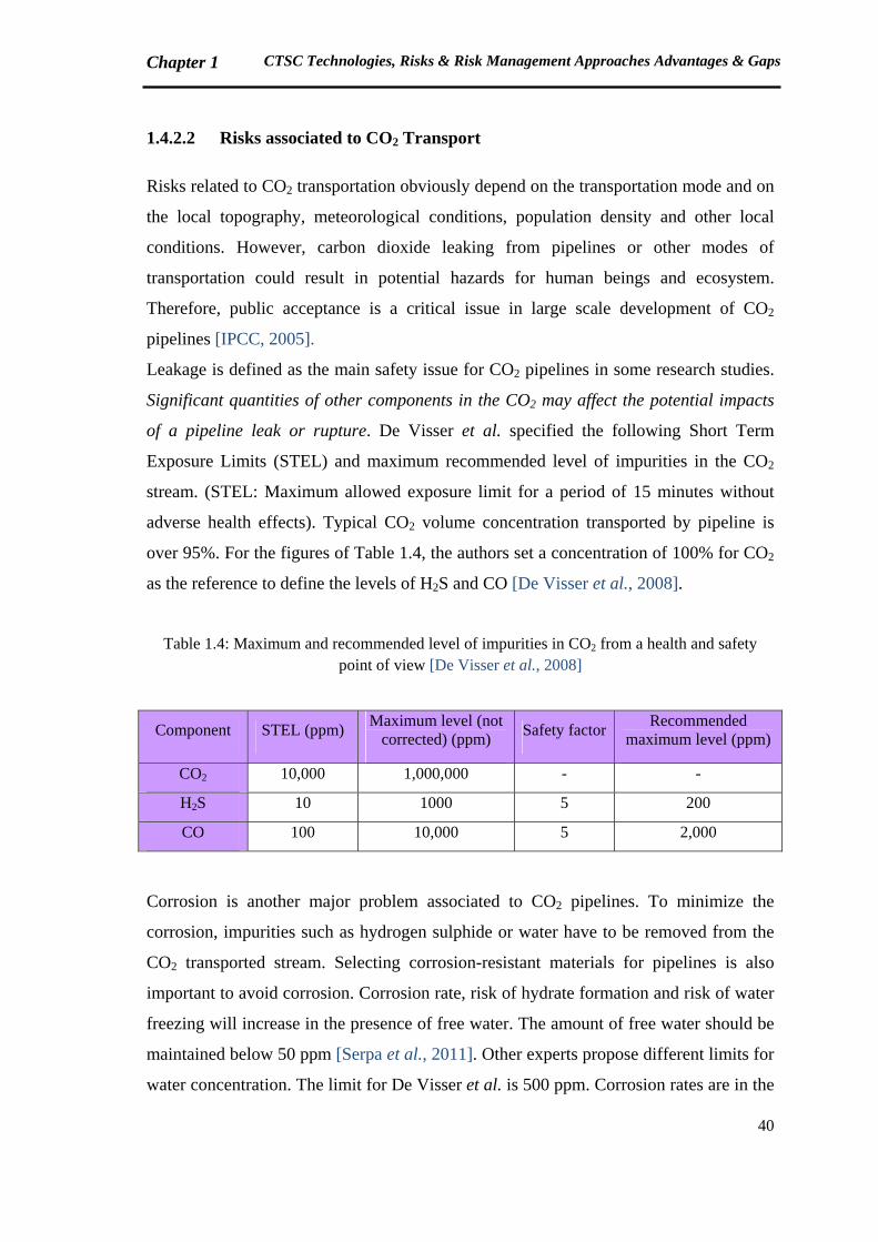
of a pipeline leak or rupture. De Visser et al. specified the following Short Term
Exposure Limits (STEL) and maximum recommended level of impurities in the CO2
stream. (STEL: Maximum allowed exposure limit for a period of 15 minutes without
adverse health effects). Typical CO2 volume concentration transported by pipeline is
over 95%. For the figures of Table 1.4, the authors set a concentration of 100% for CO2
as the reference to define the levels of H2S and CO [De Visser et al., 2008].
Table 1.4: Maximum and recommended level of impurities in CO2 from a health and safety point of view [De Visser et al., 2008]
Component STEL (ppm) Maximum level (not
corrected) (ppm) Safety factor
Recommended maximum level (ppm)
CO2 10,000 1,000,000 - -
H2S 10 1000 5 200
CO 100 10,000 5 2,000
Corrosion is another major problem associated to CO2 pipelines. To minimize the
corrosion, impurities such as hydrogen sulphide or water have to be removed from the
CO2 transported stream. Selecting corrosion-resistant materials for pipelines is also
important to avoid corrosion. Corrosion rate, risk of hydrate formation and risk of water
freezing will increase in the presence of free water. The amount of free water should be
maintained below 50 ppm [Serpa et al., 2011]. Other experts propose different limits for
water concentration. The limit for De Visser et al. is 500 ppm. Corrosion rates are in the
Chapter 1 CTSC Technologies, Risks & Risk Management Approaches Advantages & Gaps
41
order of mm/year in case of free water presence and in the order of µm/year when CO2
is dry. [De Visser et al., 2008; Seiersten, 2001]
Impurities could also change the thermodynamic behavior of the stream. As a result,
velocity and pressure drop in the pipeline are subject to change; and transport cost will
change accordingly [Serpa et al., 2011]. Two phase flow could lead to the damage of
compressors and other equipment, and hence should be avoided.
Existing gas pipelines are widely used for CO2 transportation. The main problems of the
existing pipelines are the adequacy of design pressure and remaining service life. CO2
pipelines normally operate in 85-150 bar, while natural gas pipelines operation pressure
is below 85 bar. A great number of existing pipelines have been in service for 20-40
years [Serpa et al., 2011].
1.4.2.3 Risks associated to CO2 Storage
According to [BRGM, 2005], there are two types of risks concerning geological storage
of CO2, “local risks” and "global risks". As the examples of local risks, the authors point
out the risks for human beings, animals and plants above ground, contamination of
potable water, interference with deep subsurface ecosystems, ground heave, induced
seismicity, and damage to mineral or hydrocarbon resources.
IPCC has categorized the local risks almost the same as BRGM in three groups [IPCC,
2005, p.242]:
Direct effects of elevated gas-phase CO2 concentrations in the shallow subsurface
and near-surface environment
Effects of dissolved CO2 on groundwater chemistry
Effects that arise from the displacement of fluids by the injected CO2
GCCSI argues that CO2 storage will not have an impact on surface water resources,
since the groundwater production occurs in depths of zero to 300 m, while CO2 will be
stored at more than 800 m. [GCCSI, 2011a, p.59]
“Global risks” refer to the release of CO2 in the atmosphere, which brings the initial
objective of CO2 storage (reducing atmospheric CO2 emissions) into question.
Impurities such as H2S, SO2 and NO2 could increase the risks. For instance blow-outs
containing H2S are more toxic than blow-outs containing CO2. The acid generated from
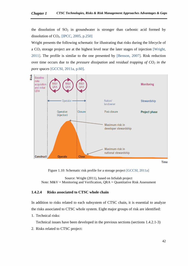
Chapter 1 CTSC Technologies, Risks & Risk Management Approaches Advantages & Gaps
42
the dissolution of SO2 in groundwater is stronger than carbonic acid formed by
dissolution of CO2. [IPCC, 2005, p.250]
Wright presents the following schematic for illustrating that risks during the lifecycle of
a CO2 storage project are at the highest level near the later stages of injection [Wright,
2011]. The profile is similar to the one presented by [Benson, 2007]. Risk reduction
over time occurs due to the pressure dissipation and residual trapping of CO2 in the
pore spaces [GCCSI, 2011a, p.60].
Figure 1.10: Schematic risk profile for a storage project [GCCSI, 2011a]
Source: Wright (2011), based on InSalah project Note: M&V = Monitoring and Verification, QRA = Quantitative Risk Assessment
1.4.2.4 Risks associated to CTSC whole chain
In addition to risks related to each subsystem of CTSC chain, it is essential to analyze
the risks associated to CTSC whole system. Eight major groups of risk are identified:
1. Technical risks:
Technical issues have been developed in the previous sections (sections 1.4.2.1-3)
2. Risks related to CTSC project:
Chapter 1 CTSC Technologies, Risks & Risk Management Approaches Advantages & Gaps
43
Mainly include the risks that affect the project progress, particularly the risks related
to the project schedule, cost and performance; and development to commercial
scales.
3. Social (Public acceptance) risks:
Public acceptance is a risk that could significantly affect CTSC projects
development. An example is Barendrecht project, in the Netherlands, which was
cancelled due to public disagreement [CCJ, 2010]. De Coninck et al. believe that the
companies are not worried that CO2 capture and storage will fail for technical
reasons. One of the concerns, however, is potential public resistance to CCS, and
some companies indicate that governments should step in to provide neutral
information to the lay public and it is imperative to find a common language for the
characterization and communication of risk both among professionals and between
professionals and the public [De Coninck et al., 2009].
4. Policy/Strategy risks:
Policy uncertainties are defined as a major risk to CTSC projects development.
GCCSI defines four policy landscapes that affect CTSC technology (Figure 1.11)
[GCCSI, 2011a, pp.ix & 70]. CTSC is an innovative technology which is involved in
global and local climate change and energy strategies. Therefore, the following
policy issues could be concerned with CTSC.
Figure 1.11: Scope of policy landscapes related to CTSC [GCCSI, 2011a]
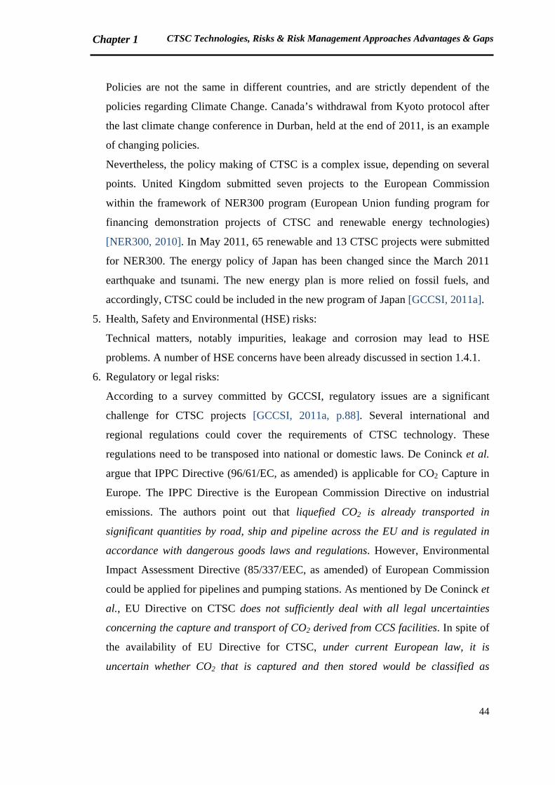
Chapter 1 CTSC Technologies, Risks & Risk Management Approaches Advantages & Gaps
44
Policies are not the same in different countries, and are strictly dependent of the
policies regarding Climate Change. Canada’s withdrawal from Kyoto protocol after
the last climate change conference in Durban, held at the end of 2011, is an example
of changing policies.
Nevertheless, the policy making of CTSC is a complex issue, depending on several
points. United Kingdom submitted seven projects to the European Commission
within the framework of NER300 program (European Union funding program for
financing demonstration projects of CTSC and renewable energy technologies)
[NER300, 2010]. In May 2011, 65 renewable and 13 CTSC projects were submitted
for NER300. The energy policy of Japan has been changed since the March 2011
earthquake and tsunami. The new energy plan is more relied on fossil fuels, and
accordingly, CTSC could be included in the new program of Japan [GCCSI, 2011a].
5. Health, Safety and Environmental (HSE) risks:
Technical matters, notably impurities, leakage and corrosion may lead to HSE
problems. A number of HSE concerns have been already discussed in section 1.4.1.
6. Regulatory or legal risks:
According to a survey committed by GCCSI, regulatory issues are a significant
challenge for CTSC projects [GCCSI, 2011a, p.88]. Several international and
regional regulations could cover the requirements of CTSC technology. These
regulations need to be transposed into national or domestic laws. De Coninck et al.
argue that IPPC Directive (96/61/EC, as amended) is applicable for CO2 Capture in
Europe. The IPPC Directive is the European Commission Directive on industrial
emissions. The authors point out that liquefied CO2 is already transported in
significant quantities by road, ship and pipeline across the EU and is regulated in
accordance with dangerous goods laws and regulations. However, Environmental
Impact Assessment Directive (85/337/EEC, as amended) of European Commission
could be applied for pipelines and pumping stations. As mentioned by De Coninck et
al., EU Directive on CTSC does not sufficiently deal with all legal uncertainties
concerning the capture and transport of CO2 derived from CCS facilities. In spite of
the availability of EU Directive for CTSC, under current European law, it is
uncertain whether CO2 that is captured and then stored would be classified as
Chapter 1 CTSC Technologies, Risks & Risk Management Approaches Advantages & Gaps
45
‘waste’. If so, the European waste laws could be applicable for CO2 storage. This
concern is currently the subject of several research studies. [De Coninck et al., 2009]
7. Organizational and human risks:
CTSC is a complex sociotechnical system which includes not only three technical
components of Capture, Transport and Storage, but also an organizational structure
containing a group of actors. The organizational and human risks are derived from
such a complexity. The complex and sociotechnical systems will be defined in
section 1.6.2.
8. Financial/Economic risks:
As previously noted, some projects have been cancelled due to financial issues.
However, GCCSI believes that governments financial support have not changed in
2011. Approximately US$ 23.5 billion has been funded for CTSC all around the
world [GCCSI, 2011a]
Considering such an overview of risks associated to CTSC activities, a list of thirty nine
risks is made based on several references, among others the documents of different
projects such as Longannet, Lacq, Barendrecht, and the recent reports of GCCSI
[GCCSI, 2009a; GCCSI, 2011a; Longannet, 2011; Feenstra et al., 2010; Kerlero de
Rosbo, 2009; CCP, 2007; Lacq Project, 2012].
Afterwards, the project phase(s) related to each risk is specified. Six main phases are
distinguished, which are not necessarily similar to GCCSI phases (presented in Table
1.1).
1. Opportunity:
The beginning period, when negotiations are carried out on the feasibility of CTSC
project
2. Definition and planning:
The phase when responsibilities and authorities of stakeholders are defined, and a
planning is made for the project
3. Engineering:
Design and sizing of installations are performed in this phase.
4. Construction:
This phase deals with construction and installation of required infrastructure and
equipment.

Chapter 1 CTSC Technologies, Risks & Risk Management Approaches Advantages & Gaps
46
5. Operation (Injection of CO2):
The period during which CO2 is injected into the geological formation
6. Post-injection (Monitoring) (also called “post-closure”):
means the period after the closure of a storage site, including the period after the
transfer of responsibility to the competent authority. [EU Directive, 2009].
At the next step, the nature of each risk and the nature of consequences are identified.
Tables of risks and their nature will be presented in Chapter 3.
The risks are inevitably interconnected and could not be studied independently.
To analyze the reasons why a CTSC project might not be progressed, the risks related to
the very first phases of the project are extracted from the overall list. The result is a list
of eighteen major risks (Table 1.5).
Table 1.5: Major risks affecting the very first phases of the project
Major risks affecting CTSC project progress (in the first phases)
1 Project permits not obtained 10 Unavailability of a monetary mechanism for CO2
2 Technology scale-up 11 Geographical infrastructure
3 Public Opposition 12 Lack of financial resources
4 Lack of knowledge/qualified resources for operating the unit
13 Lack of political support
5 Legal uncertainties 14 High cost of project
6 Uncertainties in stakeholders requirements/perceptions - Communication problems
15 Unavailability of regulations regarding different types of storage (offshore/onshore)
7 Public availability of sensitive information 16 Uncertainties regarding the storage performance (capacity/injectivity/containment)
8 Change in policies/priorities 17 Model and data issues
9 Financial crisis impact on financial support of CCS projects
18 Uncertainties related to storage monitoring
In Chapter 3, we will readdress these major risks and review the risks that could be
analyzed with our systemic approach, explained subsequently.
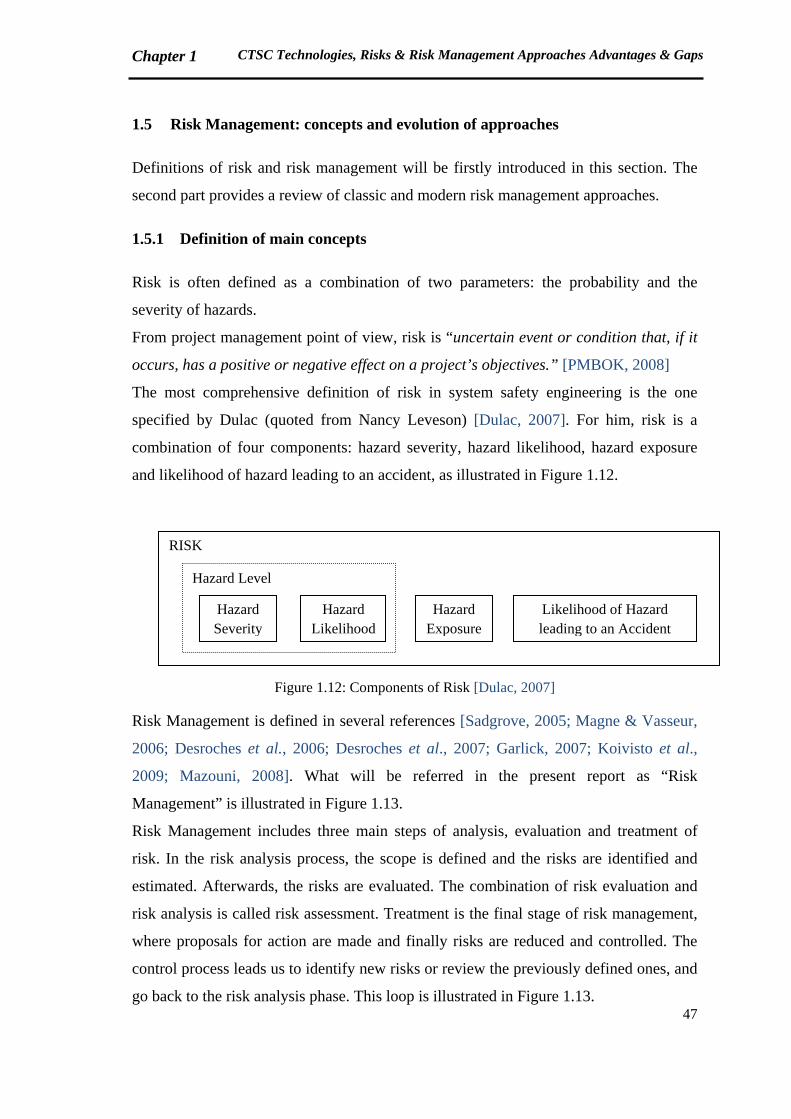
Chapter 1 CTSC Technologies, Risks & Risk Management Approaches Advantages & Gaps
47
1.5 Risk Management: concepts and evolution of approaches
Definitions of risk and risk management will be firstly introduced in this section. The
second part provides a review of classic and modern risk management approaches.
1.5.1 Definition of main concepts
Risk is often defined as a combination of two parameters: the probability and the
severity of hazards.
From project management point of view, risk is “uncertain event or condition that, if it
occurs, has a positive or negative effect on a project’s objectives.” [PMBOK, 2008]
The most comprehensive definition of risk in system safety engineering is the one
specified by Dulac (quoted from Nancy Leveson) [Dulac, 2007]. For him, risk is a
combination of four components: hazard severity, hazard likelihood, hazard exposure
and likelihood of hazard leading to an accident, as illustrated in Figure 1.12.
Figure 1.12: Components of Risk [Dulac, 2007]
Risk Management is defined in several references [Sadgrove, 2005; Magne & Vasseur,
2006; Desroches et al., 2006; Desroches et al., 2007; Garlick, 2007; Koivisto et al.,
2009; Mazouni, 2008]. What will be referred in the present report as “Risk
Management” is illustrated in Figure 1.13.
Risk Management includes three main steps of analysis, evaluation and treatment of
risk. In the risk analysis process, the scope is defined and the risks are identified and
estimated. Afterwards, the risks are evaluated. The combination of risk evaluation and
risk analysis is called risk assessment. Treatment is the final stage of risk management,
where proposals for action are made and finally risks are reduced and controlled. The
control process leads us to identify new risks or review the previously defined ones, and
go back to the risk analysis phase. This loop is illustrated in Figure 1.13.
RISK
Hazard Exposure
Likelihood of Hazard leading to an Accident
Hazard Level
Hazard Severity
Hazard Likelihood
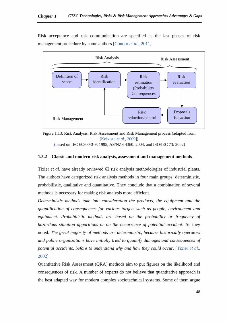
Chapter 1 CTSC Technologies, Risks & Risk Management Approaches Advantages & Gaps
48
Risk acceptance and risk communication are specified as the last phases of risk
management procedure by some authors [Condor et al., 2011].
Figure 1.13: Risk Analysis, Risk Assessment and Risk Management process (adapted from [Koivisto et al., 2009])
(based on IEC 60300-3-9: 1995, AS/NZS 4360: 2004, and ISO/IEC 73: 2002)
1.5.2 Classic and modern risk analysis, assessment and management methods
Tixier et al. have already reviewed 62 risk analysis methodologies of industrial plants.
The authors have categorized risk analysis methods in four main groups: deterministic,
probabilistic, qualitative and quantitative. They conclude that a combination of several
methods is necessary for making risk analysis more efficient.
Deterministic methods take into consideration the products, the equipment and the
quantification of consequences for various targets such as people, environment and
equipment. Probabilistic methods are based on the probability or frequency of
hazardous situation apparitions or on the occurrence of potential accident. As they
noted: The great majority of methods are deterministic, because historically operators
and public organizations have initially tried to quantify damages and consequences of
potential accidents, before to understand why and how they could occur. [Tixier et al.,
2002]
Quantitative Risk Assessment (QRA) methods aim to put figures on the likelihood and
consequences of risk. A number of experts do not believe that quantitative approach is
the best adapted way for modern complex sociotechnical systems. Some of them argue
Definition of scope
Risk identification
Risk estimation
(Probability/ Consequences
Risk evaluation
Proposals for action
Risk reduction/control
Risk Analysis Risk Assessment
Risk Management
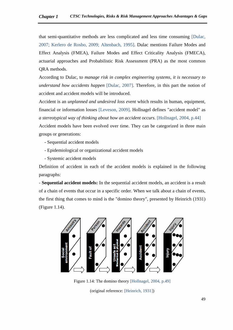
Chapter 1 CTSC Technologies, Risks & Risk Management Approaches Advantages & Gaps
49
that semi-quantitative methods are less complicated and less time consuming [Dulac,
2007; Kerlero de Rosbo, 2009; Altenbach, 1995]. Dulac mentions Failure Modes and
Effect Analysis (FMEA), Failure Modes and Effect Criticality Analysis (FMECA),
actuarial approaches and Probabilistic Risk Assessment (PRA) as the most common
QRA methods.
According to Dulac, to manage risk in complex engineering systems, it is necessary to
understand how accidents happen [Dulac, 2007]. Therefore, in this part the notion of
accident and accident models will be introduced.
Accident is an unplanned and undesired loss event which results in human, equipment,
financial or information losses [Leveson, 2009]. Hollnagel defines "accident model" as
a stereotypical way of thinking about how an accident occurs. [Hollnagel, 2004, p.44]
Accident models have been evolved over time. They can be categorized in three main
groups or generations:
- Sequential accident models
- Epidemiological or organizational accident models
- Systemic accident models
Definition of accident in each of the accident models is explained in the following
paragraphs:
- Sequential accident models: In the sequential accident models, an accident is a result
of a chain of events that occur in a specific order. When we talk about a chain of events,
the first thing that comes to mind is the "domino theory", presented by Heinrich (1931)
(Figure 1.14).
Figure 1.14: The domino theory [Hollnagel, 2004, p.49]
(original reference: [Heinrich, 1931])

Chapter 1 CTSC Technologies, Risks & Risk Management Approaches Advantages & Gaps
50
According to the domino theory, we can prevent an accident by removing one or more
blocks located before the accident block.
Hollnagel argues that the sequential accident models had been adequate for
sociotechnical systems till the middle of the 20th century. At that time, a different type
of accident model was required to explain accidents that occur in more complex
systems.
- Organizational or epidemiological accident models: In the organizational or
epidemiological accident models, accident is like spreading of a disease, as a result of a
combination of factors existing at a certain time and in a certain space. [Hollnagel,
2004; Hardy, 2010]
An example of the second generation accident models is the famous Swiss Cheese
model of James Reason (Figure 1.15). The holes of the cheese slices in the Reason's
model are continually opening, shutting, and shifting their location. The presence of
holes in any one “slice” does not normally cause a bad outcome. Usually, this can
happen only when the holes in many layers momentarily line up to permit a trajectory of
accident opportunity, bringing hazards into damaging contact with victims. [Reason,
2000]
Figure 1.15: Swiss Cheese Model [Reason, 2000]
- Systemic accident models: Systemic accident models consider the accident as an
emergent or normal phenomenon. In systemic models, accident occurs as a result of
complex interactions of system elements. Systemic models highlight the dynamic and
nonlinear aspects of systems. According to Dulac, as the complexity of engineered
systems increases, new types of accidents have started to emerge that result from the
Chapter 1 CTSC Technologies, Risks & Risk Management Approaches Advantages & Gaps
51
dysfunctional interactions between system components. These accidents result from
unplanned or unexpected interactions between different components of a system, rather
than single (or multiple) component failure [Dulac, 2007]. (original reference:
[Leveson, 2004a])
Dulac describes that traditional risk analysis methods, such as Failure Modes and Effect
Analysis (FMEA), Fault Tree Analysis (FTA) and Probabilistic Risk Assessment
(PRA), are based on event chain accident approach. Therefore, the traditional methods
of risk analysis are inappropriate for modern complex systems, because the interactions
between different components of the system are not considered in these methods. The
author also argues that organizational approaches have made an important contribution
to system safety by emphasizing the organizational aspects of accidents. Even so, the
organizational approaches often oversimplify the engineering part of the system [Dulac,
2007]. Hollnagel confirms the idea of Dulac, and proposes to find alternative methods
of risk assessment for complex systems. [Hollnagel, 2004]
Based on this reasoning, Leveson has developed a new accident model, called STAMP
(Systems-Theoretic Accident Model and Processes). This new accident model is based
on systems theory concepts. In this sociotechnical model, she takes into account several
actors of the system, from legislatures to company top management, project
management, operations management and lower levels. She argues that lack of
constraints imposed on the system design and on operations is the main cause of an
accident, instead of a series of events. According to Leveson, STAMP model could be
applied to any accidents in complex systems [Leveson, 2004a]. The details of STAMP
model approach will be presented in Chapter 2.
The notion of “systemic risk” has been also developed in several references, and among
others [IRGC, 2010]. IRGC (International Risk Governance Council) uses the OECD
(Organisation for Economic Co-operation and Development) definition and defines
systemic risks as the risks affecting the systems on which society depends. Systemic
risks are characterized by complexity, uncertainty and ambiguity. [IRGC, 2010; OECD,
2003]
Hellström affirms that risks of innovative technologies are systemic, as they are
connected to the social, economic and political infrastructure. The author argues that an
integrated assessment of risk and innovation is indispensable. He believes that emerging
Chapter 1 CTSC Technologies, Risks & Risk Management Approaches Advantages & Gaps
52
technological innovation is systemic in the sense that it could not be separated from
other aspects of the society. The author suggests the integration of governance concepts
in risk management, to make a systemic risk management approach [Hellström, 2003].
In his recent paper, Hellström presents the recommendations of the OECD project on
emerging risk (2000-2002). A main recommendation is to focus on perceptions,
experience and communication among actors in order to manage these issues as a
dynamic source of risk. OECD argues that new risk management approaches are
required for emerging technologies. The new approaches must involve all the
stakeholders, including public. The public needs to be involved even in identification of
risks. The author mentions that the new methodologies for analyzing emerging
technological risk should be systemic [Hellström, 2009].
In addition to integrity, the concept of “dynamic risk analysis” has been also remarked
in the innovative risk analysis approaches. Garbolino et al. believe that due to the
complexity of the industrial systems and their own dynamic in time and space, the risk
assessment methods need to be supported by a systemic vision of their processes. As
they affirm in their article, modeling the industrial systems is indispensable to better
understand their behavior in normal and abnormal modes [Garbolino et al., 2009].
1.6 Risk Management and CTSC
1.6.1 Available Risk Management approaches for CTSC: status and limitations
So far, several works have been carried out on risk management of CTSC all around the
world. In subsequent paragraphs, we will mention some examples of these methods to
finally make out the necessity of developing a systemic framework for CTSC risk
management.
Most of the available risk assessment or management methods are focused on one
subsystem (Capture, Transport or Storage). Due to the uncertainties concerning the
reliability of CO2 storage, risk analysis studies particularly concentrate on the storage. A
great number of studies only analyze the technical risks, and believe that the risks of
Capture and Transport could be studied by classic methods.
Chapter 1 CTSC Technologies, Risks & Risk Management Approaches Advantages & Gaps
53
1.6.1.1 CO2 Capture: available Risk Management approaches
According to International Risk Governance Council (IRGC), risks associated to CO2
capture technologies (except the innovative ones) are similar to a great number of
industrial processes for which codes, standards and operating procedures have been
developed. Consequently, risks related to CO2 capture are currently well understood.
[IRGC, 2009]
In France, analysis of major risks for CO2 Capture is carried out based on ICPE
[Bertrane, 2011]. ICPE (Installation Classée pour la Protection de l’Environnement) is
the regulatory framework applicable to CO2 Capture in France. ICPE is a French
legislation for classified installations, transcribed from Seveso II. “Classified
installation” is defined as any industrial or agricultural operation likely to create risks
or cause pollution or nuisance, notably in terms of local residents’ health and safety
[ICPE website 1].
Seveso II is a European Directive on the control of major-accident hazards involving
dangerous substances. The Directive is aimed at the prevention of major accidents
which involve dangerous substances, and the limitation of their consequences for man
and the environment, with a view to ensuring high levels of protection throughout the
Community in a consistent and effective manner. [Eurlex website]
Energy institute has recently published a guidance on hazard analysis of onshore CO2
capture and pipeline structures. The major risk highlighted in this report is the risk of
CO2 leakage or energy release throughout the system, which may lead to equipment,
human or economic losses. PHAST software is used to carry out the dispersion
calculations. PHAST is a hazard analysis package developed by DNV. The authors
affirm that it is essential to keep the risk ALARP (As Low As Reasonably Practicable).
The remaining risk has to be acceptable for workers, the whole public and
internal/external regulatory authorities. [Energy Institute, 2010]
1.6.1.2 CO2 Transport: available Risk Management approaches
Neele et al. recommend that Quantitative Risk Assessment (QRA) methods, as used for
instance in the natural gas transportation industry, could be used to study the HSE risks
of CO2 pipelines. In the report of CO2Europipe project, the authors propose a standard
Chapter 1 CTSC Technologies, Risks & Risk Management Approaches Advantages & Gaps
54
risk management method for European pipeline infrastructure. DNV practice [DNV,
2010] and ISO 31000 on Risk Management [ISO 31000, 2010] are recommended to be
used. The aim of the CO2Europipe project is to study the requirements for the
development of a large-scale CO2 transport infrastructure in Europe, between 2020 and
2050 [Neele et al., 2011].
The base of risk analysis for CO2 transport in France is GESIP n°2008/01 (Safety Study
guide, published by Groupe d’Etudes de Sécurité des Industries Pétroliers et chimiques)
[Bertrane, 2011].
Koornneef et al. from Utrecht University have reviewed the uncertainties regarding
quantitative risk assessment of CO2 transport by pipelines. They have studied the
significant parameters in release and dispersion of CO2 from pipelines and the effects on
human beings health. The assessed sources of uncertainties are: failure rates, pipeline
pressure and temperature, section length, diameter, orifice size, type and direction of
release, meteorological conditions, jet diameter, vapor mass fraction in the release and
the dose–effect relationship for CO2. Two failure scenarios are considered: puncture and
full bore rupture. Based on the results of their study, rupture is more significant than
puncture. Therefore mitigation of risks should be focused on reducing the probability
and consequences of large releases and less on reducing the probability and
consequences of small scale leaks. [Koornneef et al., 2010]
1.6.1.3 CO2 Storage: available Risk Management approaches
EU Directive presents the risk assessment process of CO2 storage in four steps: Hazard
characterization, Exposure assessment, Effects assessment and Risk characterization.
Definition of each step is summarized in the following paragraphs [EU Directive,
2009]:
1) Hazard characterization: means characterizing the potential for leakage from the
storage complex. This includes specifying the potential leakage pathways,
potential leakage rates, process specifications affecting potential leakage (e.g.
maximum reservoir pressure, maximum injection rate and temperature)
2) Exposure assessment: is carried out based on the characteristics of the
environment and the distribution and activities of the human population above
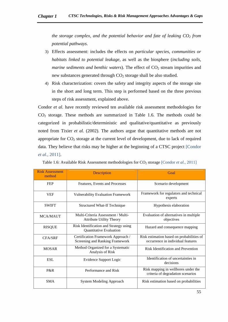
Chapter 1 CTSC Technologies, Risks & Risk Management Approaches Advantages & Gaps
55
the storage complex, and the potential behavior and fate of leaking CO2 from
potential pathways.
3) Effects assessment: includes the effects on particular species, communities or
habitats linked to potential leakage, as well as the biosphere (including soils,
marine sediments and benthic waters). The effect of CO2 stream impurities and
new substances generated through CO2 storage shall be also studied.
4) Risk characterization: covers the safety and integrity aspects of the storage site
in the short and long term. This step is performed based on the three previous
steps of risk assessment, explained above.
Condor et al. have recently reviewed ten available risk assessment methodologies for
CO2 storage. These methods are summarized in Table 1.6. The methods could be
categorized in probabilistic/deterministic and qualitative/quantitative as previously
noted from Tixier et al. (2002). The authors argue that quantitative methods are not
appropriate for CO2 storage at the current level of development, due to lack of required
data. They believe that risks may be higher at the beginning of a CTSC project [Condor
et al., 2011].
Table 1.6: Available Risk Assessment methodologies for CO2 storage [Condor et al., 2011]
Risk Assessment method
Description Goal
FEP Features, Events and Processes Scenario development
VEF Vulnerability Evaluation Framework Framework for regulators and technical experts
SWIFT Structured What-If Technique Hypothesis elaboration
MCA/MAUT Multi-Criteria Assessment / Multi-Attribute Utility Theory
Evaluation of alternatives in multiple objectives
RISQUE Risk Identification and Strategy using Quantitative Evaluation
Hazard and consequence mapping
CFA/SRF Certification Framework Approach / Screening and Ranking Framework
Risk estimation based on probabilities of occurrence in individual features
MOSAR Method Organized for a Systematic Analysis of Risk
Risk Identification and Prevention
ESL Evidence Support Logic Identification of uncertainties in decisions
P&R Performance and Risk Risk mapping in wellbores under the criteria of degradation scenarios
SMA System Modeling Approach Risk estimation based on probabilities
Chapter 1 CTSC Technologies, Risks & Risk Management Approaches Advantages & Gaps
56
In France, BRGM is one of the predominant institutes working on risk management of
CO2 storage. BRGM specialists study the probable impacts of CO2 leakage on drinkable
water aquifers, human health and environment. [Fabriol, 2009; Bouc et al., 2009]
FEP (Features, Events, Processes) analysis is one of the approaches which has been
already applied for risk assessment of CO2 storage. FEP is a method for defining
scenarios relevant to safety assessment of the geological disposal of radioactive wastes.
The same approach has been implemented for long-term geological storage of CO2. In
the field of CO2 storage, "Feature" refers to the geological formation and its
characteristics. "Events" are what may or will happen in the future, for example
earthquake. And "Processes" are the ongoing matters that influence the evolution of the
system, like the erosion of the land surface. As a result of workshop discussions and
brainstorming, a database has been developed for CO2 storage including 200 FEPs in
eight categories. (for details, refer to Quintessa report [Savage et al., 2004])
FEP analysis has been applied for different CO2 storage projects, such as Weyburn
[PTRC, 2004] or Illinois Basin-Decateur project [Hnottavange-Telleen et al., 2009].
Oldenburg et al. have developed a certification framework to certify the effectiveness
and safety of CO2 storage. They have reviewed some available risk assessment methods
for storage, including a system-modeling approach (CO2 PENS), which studies the
whole CTSC chain, from capture to storage. However, the authors believe that such
comprehensive methods are so complex due to several uncertainties. [Oldenburg et al.,
2009]
Oxand (an international engineering and consulting company specialized in industrial
risk management) applies a classic risk management approach for storage
(Identification, Estimation, Evaluation, Treatment), previously presented in Figure 1.13.
For the identification of risks, FMECA (Failure Mode, Effects and Criticality Analysis)
is used, which is a well-known classic method. For the risk estimation, they use the
quantitative and qualitative methods to define the probability and severity of risks. The
risk evaluation is carried out by ALARP (As Low As Reasonably Practicable) method.
The treatment is categorized in four levels: risk control, spreading the risk over a time
period, share the risk, and risk transfer. Oxand experts believe that many well-known
methods could be used for Capture and Transport. [Chammas & Poupard, 2011]
Chapter 1 CTSC Technologies, Risks & Risk Management Approaches Advantages & Gaps
57
Benson proposes to study lessons learned from analogous technologies in order to better
understand the risks associated with CO2 storage projects. She remarks three examples
as the analogues of CO2 storage: natural disasters like the catastrophic volcanic release
of Lake Nyos in Cameroon, 1986, and the storage of natural gas and nuclear wastes.
[Benson, 2002]
Perry has recently studied the experiences of natural gas storage industry and the
potential application to CO2 geological storage. He has reviewed the relevant literature
and performed surveys/interviews with operators in Europe, Canada and the United
States. An important finding of this study is that only 10 of about 600 storage reservoirs
operated in United States, Canada and Europe have been identified to have experienced
leakage. Four due to cap rock issues, five due to well bore integrity, and one due to
reservoir selection (too shallow). Monitoring the geological formation is the most
significant factor that he mentions for controlling the risks. [Perry, 2005]
1.6.1.4 CTSC whole chain: available Risk Management approaches
As discussed before, a great number of risk management approaches cover one aspect
of CTSC chain. However, there are examples in the literature that highlight the
necessity of an integrative risk management method for CTSC.
Farret et al. underline the importance of developing an integrated approach in risk
analysis of CTSC due to interdependency of four steps, i.e. Capture, Transport,
Injection to the reservoir and Long-term Storage. [Farret et al., 2009]
Gerstenberger et al. believe that a comprehensive risk assessment method does not yet
exist for CTSC and needs to be developed. [Gerstenberger et al., 2009]
The (semi-)integrated studies that have been already carried out on CTSC risk
management are as following:
GCCSI applies the Australian and New Zealand Standard for Risk Management
(AS/NZS 4360: 2004) to define the likelihood and consequences of a set of extreme
risks associated to integrated CTSC projects. Seventeen risks are identified with public,
governmental/regulatory/policy, business case and technical nature. [GCCSI, 2009a]
Det Norske Veritas (DNV) has studied HSE issues related to large-scale capture,
transport and storage of CO2. In their study, an almost integrated analysis has been
performed; hence capture, transport and injection phases are considered in the analysis
Chapter 1 CTSC Technologies, Risks & Risk Management Approaches Advantages & Gaps
58
(storage phase is not included). DNV method for risk assessment of large-scale CTSC
projects is SWIFT (Structured What IF Technique) analysis. SWIFT analysis is an
expert panel/workshop approach to identify potential hazards and uncertainties. Prior to
the workshop, a questionnaire was sent to the stakeholders in order to gather their ideas
about HSE issues regarding CTSC (from capture to injection phase). The participants
have mentioned the lack of an integrated approach as a concern in HSE risk
management of CTSC, an approach that takes into account CTSC whole chain [Johnsen
et al., 2009].
Another work on CTSC integrated risk analysis is the approach presented by Kerlero de
Rosbo for the Belchatow project, in which Alstom was responsible to develop a CTSC
plant for a coal-based power plant in Poland. Technical, financial, organizational, socio-
political and regulatory risks associated with a large-scale CTSC project have been
studied in that project. The deliverable was a risk register provided in panel discussions
carried out to meet the project objectives. [Kerlero de Rosbo, 2009]
1.6.2 Requirement of a novel systemic approach for CTSC Risk Management
CTSC is a complex sociotechnical system which includes a technical system with three
components of Capture, Transport and Storage. The social part of CTSC sociotechnical
system involves an organizational structure containing a group of actors. The interface
between organizational, human and technical aspects could initiate a failure in the
system. In the succeeding part, we will recall the definition of system, complex system,
and sociotechnical system.
Durand points out six definitions for system [Durand, 2010]:
1. System is an organized whole, made up of interdependent elements that can be
defined as relative to each other according to their place in this whole. (definition of
Ferdinand de Saussure, Swiss linguist)
2. System is a set of units and their mutual interrelations. (definition of Karl Ludwig
von Bertalanffy, Austrian-born biologist)
3. System is a set of elements linked by a set of relationships (definition of Jacques
Lesourne, French economist)
4. System is a set of elements in dynamic interaction which are organized based on a
purpose. (Joël de Rosnay, French biologist)
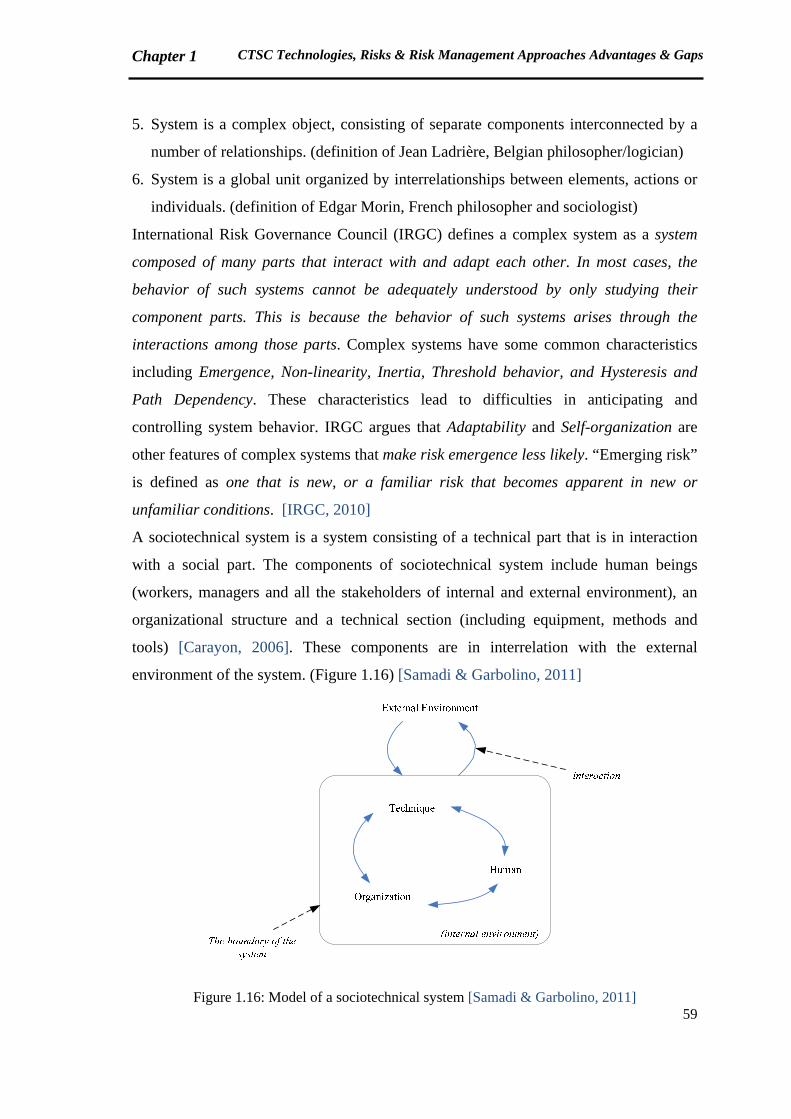
Chapter 1 CTSC Technologies, Risks & Risk Management Approaches Advantages & Gaps
59
5. System is a complex object, consisting of separate components interconnected by a
number of relationships. (definition of Jean Ladrière, Belgian philosopher/logician)
6. System is a global unit organized by interrelationships between elements, actions or
individuals. (definition of Edgar Morin, French philosopher and sociologist)
International Risk Governance Council (IRGC) defines a complex system as a system
composed of many parts that interact with and adapt each other. In most cases, the
behavior of such systems cannot be adequately understood by only studying their
component parts. This is because the behavior of such systems arises through the
interactions among those parts. Complex systems have some common characteristics
including Emergence, Non-linearity, Inertia, Threshold behavior, and Hysteresis and
Path Dependency. These characteristics lead to difficulties in anticipating and
controlling system behavior. IRGC argues that Adaptability and Self-organization are
other features of complex systems that make risk emergence less likely. “Emerging risk”
is defined as one that is new, or a familiar risk that becomes apparent in new or
unfamiliar conditions. [IRGC, 2010]
A sociotechnical system is a system consisting of a technical part that is in interaction
with a social part. The components of sociotechnical system include human beings
(workers, managers and all the stakeholders of internal and external environment), an
organizational structure and a technical section (including equipment, methods and
tools) [Carayon, 2006]. These components are in interrelation with the external
environment of the system. (Figure 1.16) [Samadi & Garbolino, 2011]
Figure 1.16: Model of a sociotechnical system [Samadi & Garbolino, 2011]

Chapter 1 CTSC Technologies, Risks & Risk Management Approaches Advantages & Gaps
60
With the definitions provided in this section, we could consider CTSC as a complex
sociotechnical system. As discussed in section 1.5.2, traditional risk management
methods are inappropriate for such systems, and novel systemic approaches are
required.
A systemic approach will be presented in subsequent chapters for CTSC risk
management. The proposed approach is based on systems theory concepts, system
dynamics and STAMP, which will be introduced in Chapter 2.
Chapter 1 CTSC Technologies, Risks & Risk Management Approaches Advantages & Gaps
61
Summary, Chapter 1
In this chapter, the position of Capture, Transport and Storage of CO2 (CTSC) in
climate change mitigation was introduced. An overview of CTSC projects in the world
was also presented. A section was devoted to the introduction of different Capture,
Transport and Storage processes. Risks associated to each subsystem and the whole
chain were presented. Risks related to the whole chain in a complex sociotechnical
framework were classified in eight groups: Technical, Risks related to Project, Social,
Policy/Strategy, HSE, Regulatory, Organizational/Human and Financial/Economic.
Notions of risk and risk management were introduced, followed by a general recall of
classic and modern risk assessment methods. This section includes accident models
evolution, which is required to understand the necessity of proposing a systemic risk
management framework for CTSC, as an emerging technology. In the last part,
available risk management approaches for Capture, Transport and Storage were
reviewed individually. Finally, integrated (systemic) approaches were argued as
essential need of risk management for CTSC.
Chapter 1 CTSC Technologies, Risks & Risk Management Approaches Advantages & Gaps
62
Résumé (French Summary of Chapter 1)
Dans ce chapitre, le rôle de la technologie de Captage, Transport et Stockage de CO2
(CTSC) par rapport au changement climatique a été introduit et une vue d’ensemble des
projets de CTSC dans le monde a été également présentée. Une partie a été consacrée à
l'introduction de différents processus de Captage, Transport et Stockage de CO2. Les
risques associés à chaque sous-système (C, T et S) et à l'ensemble de la chaîne ont été
présentés. Les risques liés au système global, considéré comme un système
sociotechnique complexe, sont classés selon huit principales catégories. Ces catégories
comprennent les risques techniques, les risques liés au projet, les risques sociaux, les
risques politiques/stratégiques, les risques liés aux Santé, Sécurité et Environnement
(SSE), les risques réglementaires, les risques organisationnels/humains et les risques
financières/économiques. Les notions du risque et de la gestion des risques ont été
introduites, suite à un rappel général des méthodes classiques et de celles plus récentes
d'évaluation des risques. Cette partie inclut ainsi l’étude de l’évolution des modèles
d’accident permettant de comprendre pourquoi une approche systémique de
management des risques est indispensable pour le CTSC qui représente une technologie
émergente. Dans la dernière partie, les méthodologies de gestion des risques disponibles
pour le Captage, le Transport et le Stockage ont été étudiées individuellement. La
conclusion propose que les approches intégrées (systémiques) sont essentielles pour la
gestion des risques des activités de CTSC.

63
Chapter 2: Contribution of Systems Theory and System Dynamics to CTSC Risk Management
Chapter 2 Contribution of Systems Theory and System Dynamics to CTSC Risk Management
64
In this chapter, we will argue how systems theory, system dynamics, and STAMP
(Systems-Theoretic Accident Model and Processes) approach can contribute to the risk
management of CTSC projects. The chapter includes four sections:
The first section is devoted to the introduction of systems theory and system dynamics.
In section 2.2, a general review of system dynamics application fields is provided.
In the third section, current dynamics of CTSC technology are presented.
We will finally discuss how systemic approaches, and specially STAMP, could analyze
the dynamics of CTSC.
2.1 Systems Theory and System Dynamics: Introduction and key concepts
2.1.1 Systems Theory
The modern concept of system emerged in the second half of the twentieth century in
different scientific fields. Durand (2010) names five famous pioneers who invented the
novel concept of system:
- Ludwig von Bertanlanffy (1901-1972), the Austrian biologist, who is the creator of
“General Systems Theory”
- Norbert Wiener (1894-1964), American mathematician and professor at MIT
(Massachusetts Institute of Technology), who applied the systems theory in control
and communications engineering [Leveson, 2009]. His famous book is
“Cybernetics”, published in 1948 [Wiener, 1948].
- Claude Elwood Shannon (1916-2001), American mathematician and
telecommunication engineer, who has published “A mathematical theory of
communication” in 1948. [Shannon, 1948]
- Warren Sturgis McCulloch (1898-1969), American neurophysiologist, who
broadened his research in mathematics and engineering.
- Jay Wright Forrester (1918- ), American engineer and professor at MIT, who
developed the application of systems theory in the industrial dynamics and created
System Dynamics.
Development of the modern systems theory was essentially localized in the United
States. Nevertheless, in 1960s, 1970s the phenomenon was introduced out of the US,
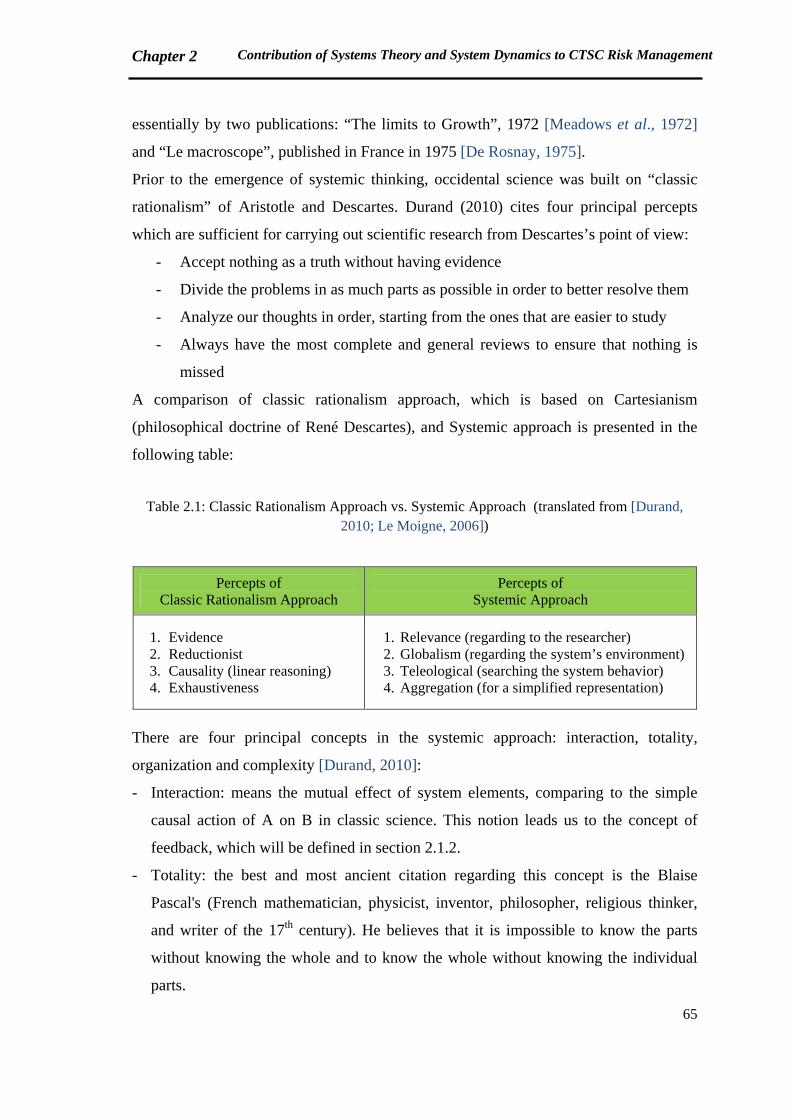
Chapter 2 Contribution of Systems Theory and System Dynamics to CTSC Risk Management
65
essentially by two publications: “The limits to Growth”, 1972 [Meadows et al., 1972]
and “Le macroscope”, published in France in 1975 [De Rosnay, 1975].
Prior to the emergence of systemic thinking, occidental science was built on “classic
rationalism” of Aristotle and Descartes. Durand (2010) cites four principal percepts
which are sufficient for carrying out scientific research from Descartes’s point of view:
- Accept nothing as a truth without having evidence
- Divide the problems in as much parts as possible in order to better resolve them
- Analyze our thoughts in order, starting from the ones that are easier to study
- Always have the most complete and general reviews to ensure that nothing is
missed
A comparison of classic rationalism approach, which is based on Cartesianism
(philosophical doctrine of René Descartes), and Systemic approach is presented in the
following table:
Table 2.1: Classic Rationalism Approach vs. Systemic Approach (translated from [Durand, 2010; Le Moigne, 2006])
Percepts of Classic Rationalism Approach
Percepts of Systemic Approach
1. Evidence 2. Reductionist 3. Causality (linear reasoning) 4. Exhaustiveness
1. Relevance (regarding to the researcher) 2. Globalism (regarding the system’s environment) 3. Teleological (searching the system behavior) 4. Aggregation (for a simplified representation)
There are four principal concepts in the systemic approach: interaction, totality,
organization and complexity [Durand, 2010]:
- Interaction: means the mutual effect of system elements, comparing to the simple
causal action of A on B in classic science. This notion leads us to the concept of
feedback, which will be defined in section 2.1.2.
- Totality: the best and most ancient citation regarding this concept is the Blaise
Pascal's (French mathematician, physicist, inventor, philosopher, religious thinker,
and writer of the 17th century). He believes that it is impossible to know the parts
without knowing the whole and to know the whole without knowing the individual
parts.
Chapter 2 Contribution of Systems Theory and System Dynamics to CTSC Risk Management
66
- Organization: could be defined as a set of relations among the elements or
individuals which forms a new unit, without necessarily the same qualities of the
components.
- Complexity: Edgar Morin is one of the pioneers in complexity. He believes that
complexity refers not only to the quantity of elements and interactions in the system,
but also to the uncertainties, disinclinations and unpredictable phenomena (the
concept of "emergence" in complex systems which was introduced in Chapter 1,
section 1.6.2). Morin states that complexity always deals with hazard [Morin, 2005,
p.49]. This idea directs us to the application of systemic approach in the field of risk
management which will be developed in sections 2.2 and 2.4.
Hardy cites five characteristics of systems, which are more or less similar to the
abovementioned concepts. These characteristics, cited from [Gharajedaghi, 2006]
consist of Interaction, Structure, Emergence, Auto-organization and Feedback. [Hardy,
2010]
2.1.2 System Dynamics
System dynamics has its roots in control engineering, cybernetics and general system
science. [Fuchs, 2006]
System dynamics is a methodology to understand the structure and behavior of complex
systems, created during the mid 1950s by Jay W. Forrester in the Massachusetts
Institute of Technology (MIT). He defines system dynamics as a combination of theory,
methods and philosophy required to analyze the behavior of systems. [Forrester, 1991]
System dynamics is grounded in the theory of nonlinear dynamics and feedback control
developed in mathematics, physics and engineering. [Sterman, 2000, p.5]
The advent of system dynamics was a pencil and paper simulation of General Electric
inventory control system. Forrester showed by this hand simulation that the source of
instability in General Electric employment was due to internal structure of the company
not to external forces such as the business cycle [Forrester, 1996; Radzicki & Taylor,
1997].
Thereafter, system dynamics has been applied in various fields from management to
environmental change, politics, economic behavior, medicine, engineering, and recently
for analyzing accidents and risks [Forrester, 1991; Leveson, 2004a,b; Stringfellow,
Chapter 2 Contribution of Systems Theory and System Dynamics to CTSC Risk Management
67
2010; Garbolino et al., 2009; Garbolino et al., 2010; Dulac, 2007]. The application
disciplines of system dynamics will be discussed in section 2.2.
Models and modeling are the most essential concepts in system dynamics. Models are
simplifications of reality which help people to clarify their thinking and improve their
understanding of the world. Paul Valéry (French writer, poet, philosopher and
epistemologist) believes that models are the only bases of our thinking [Durand, 2010].
All human beings have a mental representation of the systems around them, such as
families, universities, cities, etc. These mental models are flexible and rich in detail, but
they are often fuzzy, incomplete and imprecise. That's why system dynamicists propose
to decision-makers to apply system dynamics to map out their mental models on the
computer and follow the evolution of the system through the computer model [Radzicki
& Taylor, 1997]. The process of modeling a system and studying its behavior over time
is termed "dynamic modeling".
As Forrester affirms, an industrial activity is made up of six interconnected networks:
materials, orders, money, capital equipment, personnel and information. The
information network interconnects the other five. [Forrester, 1968]
General steps of dynamic modeling presented by Forrester (1968) are as follows:
1. Identify the problem and the questions to be answered
2. Gathering required information (for a production-distribution system, these
information include organizational structure, delays in decisions and actions, policies
governing purchases and inventories)
3. Establishment of mathematical description of the system
4. Simulation (tracing of a specific time history)
5. Interpretation of the results
6. System revision (redesign of system structures and policies)
7. Reiterated experimentation
The process of dynamic modeling is illustrated in Figure 2.1:
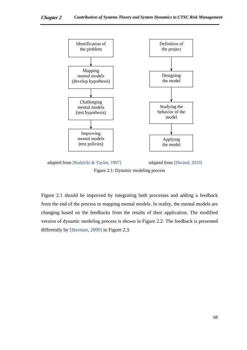
Chapter 2 Contribution of Systems Theory and System Dynamics to CTSC Risk Management
68
adapted from [Radzicki & Taylor, 1997] adapted from [Durand, 2010]
Figure 2.1: Dynamic modeling process
Figure 2.1 should be improved by integrating both processes and adding a feedback
from the end of the process to mapping mental models. In reality, the mental models are
changing based on the feedbacks from the results of their application. The modified
version of dynamic modeling process is shown in Figure 2.2. The feedback is presented
differently by [Sterman, 2000] in Figure 2.3.
Identification of the problem
Mapping mental models
(develop hypothesis)
Challenging mental models
(test hypothesis)
Improving mental models (test policies)
Definition of the project
Designing the model
Studying the behavior of the
model
Applying the model
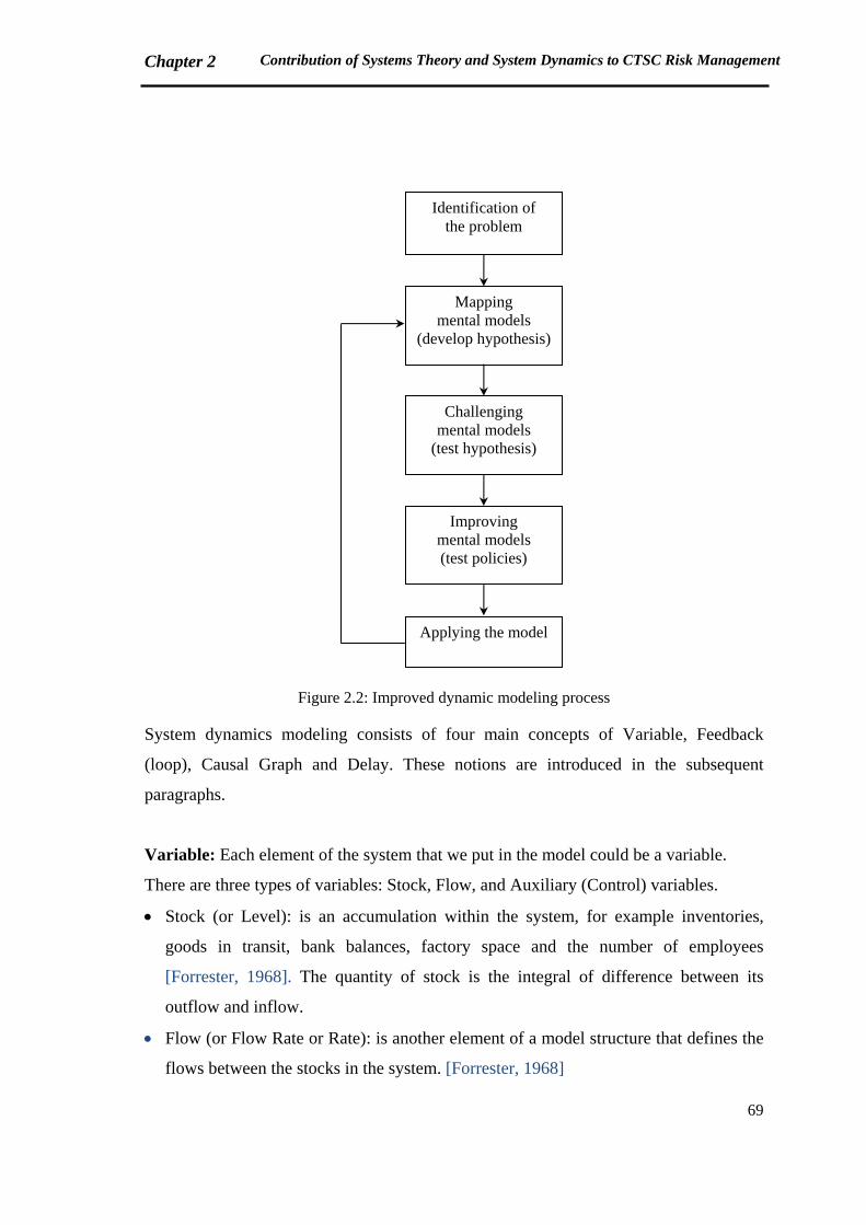
Chapter 2 Contribution of Systems Theory and System Dynamics to CTSC Risk Management
69
Figure 2.2: Improved dynamic modeling process
System dynamics modeling consists of four main concepts of Variable, Feedback
(loop), Causal Graph and Delay. These notions are introduced in the subsequent
paragraphs.
Variable: Each element of the system that we put in the model could be a variable.
There are three types of variables: Stock, Flow, and Auxiliary (Control) variables.
Stock (or Level): is an accumulation within the system, for example inventories,
goods in transit, bank balances, factory space and the number of employees
[Forrester, 1968]. The quantity of stock is the integral of difference between its
outflow and inflow.
Flow (or Flow Rate or Rate): is another element of a model structure that defines the
flows between the stocks in the system. [Forrester, 1968]
Identification of the problem
Mapping mental models
(develop hypothesis)
Challenging mental models
(test hypothesis)
Improving mental models (test policies)
Applying the model

Chapter 2 Contribution of Systems Theory and System Dynamics to CTSC Risk Management
70
The following equation shows the mathematical relation between the stocks and
flows:
or According to Forrester, Stocks and Flows exist in all six networks that may constitute
a system: materials, orders, money, personnel, capital equipment and information
[Forrester, 1968].
One of the most challenging parts of dynamic modeling is to correctly distinguish the
stocks and the flows. As Forrester proposes, in order to determine whether a variable
is a stock or a flow, we should see whether or not the variable would continue to
exist in the system. The variable which will continue to exist is a stock (such as
inventories of a warehouse). Flow is the variable that could be stopped (like
receiving and shipping goods).
Auxiliary (Control) variable: is a variable that is computed from other variables at a
given time. Auxiliaries are typically the most numerous variable type. [Vensim,
2010, p.22]
Feedback and Feedback Loop: From a system dynamics point of view, a system can
be classified as "open" or "closed". Open systems are the ones in which the outputs
have no influence on the inputs of the system. In closed systems, the outputs do have
influence on the inputs. Most of the systems in the real world are closed systems and the
effect of output on input is called Feedback. [Radzicki & Taylor, 1997]
There are two types of feedback loops in a closed system: positive (or reinforcing) and
negative (or balancing) loops. Positive feedback loops are the ones which destabilize the
system and cause them to run away from their current situation whilst negative
feedback loops stabilize the system [Radzicki & Taylor, 1997]. In a positive feedback
loop, the variables change in the same direction, whereas they will change in the
opposite direction in a negative feedback loop. In other words, in a positive feedback, if
the first variable increases, the second variable will be increased (the same direction as
the first variable). However, in a negative feedback, an increase in the first variable
leads to a decrease in the second variable (the opposite direction).
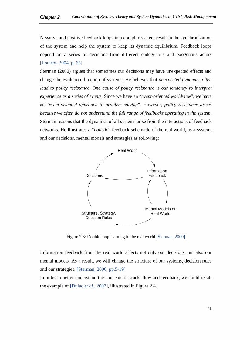
Chapter 2 Contribution of Systems Theory and System Dynamics to CTSC Risk Management
71
Negative and positive feedback loops in a complex system result in the synchronization
of the system and help the system to keep its dynamic equilibrium. Feedback loops
depend on a series of decisions from different endogenous and exogenous actors
[Louisot, 2004, p. 65].
Sterman (2000) argues that sometimes our decisions may have unexpected effects and
change the evolution direction of systems. He believes that unexpected dynamics often
lead to policy resistance. One cause of policy resistance is our tendency to interpret
experience as a series of events. Since we have an “event-oriented worldview”, we have
an “event-oriented approach to problem solving”. However, policy resistance arises
because we often do not understand the full range of feedbacks operating in the system.
Sterman reasons that the dynamics of all systems arise from the interactions of feedback
networks. He illustrates a “holistic” feedback schematic of the real world, as a system,
and our decisions, mental models and strategies as following:
Real World
InformationFeedback
Mental Models ofReal WorldStructure, Strategy,
Decision Rules
Decisions
Figure 2.3: Double loop learning in the real world [Sterman, 2000]
Information feedback from the real world affects not only our decisions, but also our
mental models. As a result, we will change the structure of our systems, decision rules
and our strategies. [Sterman, 2000, pp.5-19]
In order to better understand the concepts of stock, flow and feedback, we could recall
the example of [Dulac et al., 2007], illustrated in Figure 2.4.
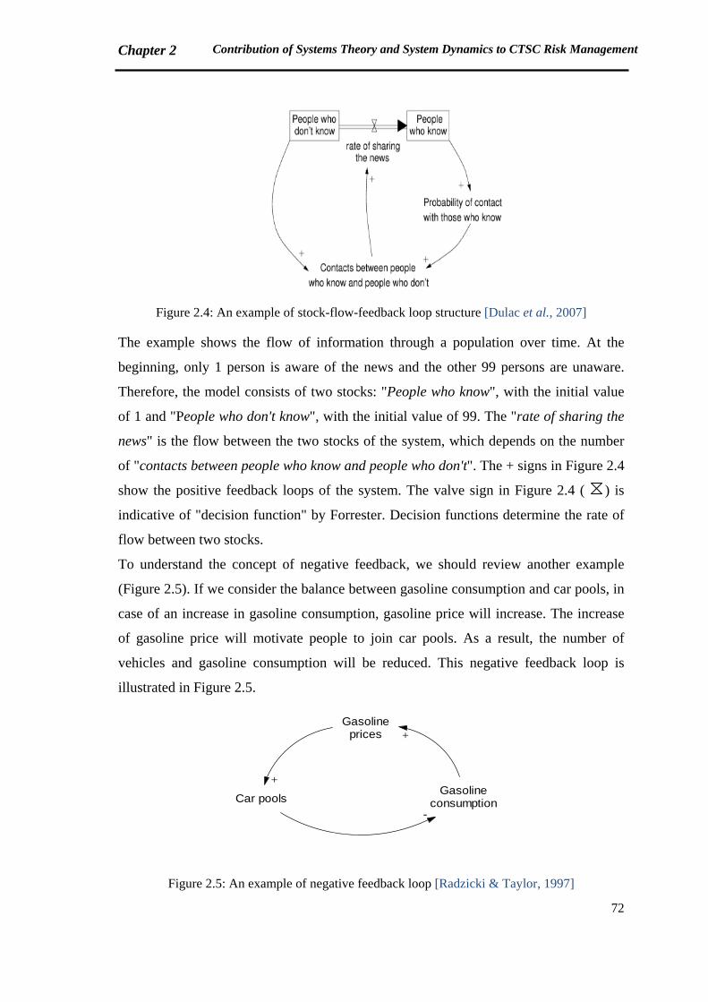
Chapter 2 Contribution of Systems Theory and System Dynamics to CTSC Risk Management
72
Figure 2.4: An example of stock-flow-feedback loop structure [Dulac et al., 2007]
The example shows the flow of information through a population over time. At the
beginning, only 1 person is aware of the news and the other 99 persons are unaware.
Therefore, the model consists of two stocks: "People who know", with the initial value
of 1 and "People who don't know", with the initial value of 99. The "rate of sharing the
news" is the flow between the two stocks of the system, which depends on the number
of "contacts between people who know and people who don't". The + signs in Figure 2.4
show the positive feedback loops of the system. The valve sign in Figure 2.4 ( ) is
indicative of "decision function" by Forrester. Decision functions determine the rate of
flow between two stocks.
To understand the concept of negative feedback, we should review another example
(Figure 2.5). If we consider the balance between gasoline consumption and car pools, in
case of an increase in gasoline consumption, gasoline price will increase. The increase
of gasoline price will motivate people to join car pools. As a result, the number of
vehicles and gasoline consumption will be reduced. This negative feedback loop is
illustrated in Figure 2.5.
Gasolineprices
GasolineconsumptionCar pools
+
-
+
Figure 2.5: An example of negative feedback loop [Radzicki & Taylor, 1997]

Chapter 2 Contribution of Systems Theory and System Dynamics to CTSC Risk Management
73
Causal graphs: are the diagrams containing the network of feedback loops, or the
interactions of the system variables.
The examples concerning CTSC system will be presented in Chapter 3.
Delay: is another important concept in system dynamics. Radzicki and Taylor explain
the concept of delay by the fact that events in the world do not occur instantaneously.
Instead, there is often a significant lag between cause and effect. The longer the delay
between cause and effect, the more likely it is that a decision maker will not perceive a
connection between the two. [Radzicki & Taylor, 1997]
Several software packages are available for dynamic modeling such as VENSIM®,
STELLA®, GOLDSIM®, ITHINK® and POWERSIM®. Models presented in the current
report have been developed by VENSIM®.
Richardson (2011) believes that “endogenous point of view” is in fact the foundation of
system dynamics. In this viewpoint, system is considered as cause. System dynamicists
use system thinking, management insights and computer simulation to:
- hypothesize, test and refine endogenous explanations of system change, and
- use those explanations to guide policy and decision making
Sterman asserts Richardson idea and mentions that system dynamics seeks endogenous
explanations for phenomena. “Endogenous” is defined as “arising from within” by
[Sterman, 2000, p.95].
Richardson remarks the concept of agency in system dynamics by asking: Who are the
actors in the dynamics of a complex system and how do their perceptions, pressures,
and policies interact?
Four possibilities are conceivable between the perceptions of decision makers and the
reality (Figure 2.6). In the first and second ones ( and ), the decision maker
perceptions match the reality. In the first case ( ), decision makers have an
exogenous view about a phenomenon which is exogenously created. In this case, the
best choice is to accept the fate, predict and prepare for whatever we believe is coming.
In the second case ( ), decision makers have a right endogenous view of an
endogenous phenomenon. This is the case that could be well understood by the
feedback notion in system dynamics. As shown in Figure 2.6 by smileys, this case is the
most favorable one. In the third box of Figure 2.6 ( ), the situation is externally
created. However, we are attempting to find endogenous explanations to control the
21
1
2
3
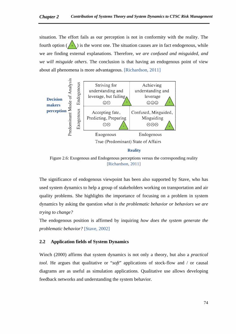
Chapter 2 Contribution of Systems Theory and System Dynamics to CTSC Risk Management
74
situation. The effort fails as our perception is not in conformity with the reality. The
fourth option ( ) is the worst one. The situation causes are in fact endogenous, while
we are finding external explanations. Therefore, we are confused and misguided, and
we will misguide others. The conclusion is that having an endogenous point of view
about all phenomena is more advantageous. [Richardson, 2011]
Figure 2.6: Exogenous and Endogenous perceptions versus the corresponding reality
[Richardson, 2011]
The significance of endogenous viewpoint has been also supported by Stave, who has
used system dynamics to help a group of stakeholders working on transportation and air
quality problems. She highlights the importance of focusing on a problem in system
dynamics by asking the question what is the problematic behavior or behaviors we are
trying to change?
The endogenous position is affirmed by inquiring how does the system generate the
problematic behavior? [Stave, 2002]
2.2 Application fields of System Dynamics
Winch (2000) affirms that system dynamics is not only a theory, but also a practical
tool. He argues that qualitative or “soft” applications of stock-flow and / or causal
diagrams are as useful as simulation applications. Qualitative use allows developing
feedback networks and understanding the system behavior.
Decision makers perception
Reality
4
3 2
1 4
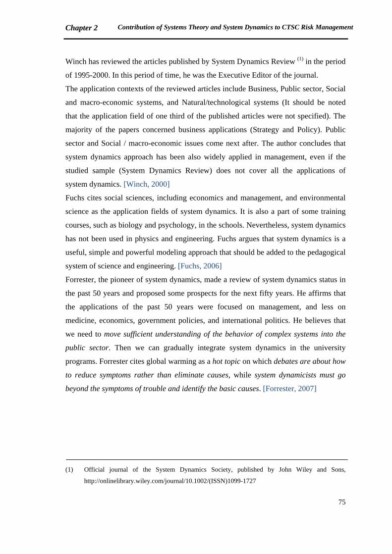
Chapter 2 Contribution of Systems Theory and System Dynamics to CTSC Risk Management
75
Winch has reviewed the articles published by System Dynamics Review (1) in the period
of 1995-2000. In this period of time, he was the Executive Editor of the journal.
The application contexts of the reviewed articles include Business, Public sector, Social
and macro-economic systems, and Natural/technological systems (It should be noted
that the application field of one third of the published articles were not specified). The
majority of the papers concerned business applications (Strategy and Policy). Public
sector and Social / macro-economic issues come next after. The author concludes that
system dynamics approach has been also widely applied in management, even if the
studied sample (System Dynamics Review) does not cover all the applications of
system dynamics. [Winch, 2000]
Fuchs cites social sciences, including economics and management, and environmental
science as the application fields of system dynamics. It is also a part of some training
courses, such as biology and psychology, in the schools. Nevertheless, system dynamics
has not been used in physics and engineering. Fuchs argues that system dynamics is a
useful, simple and powerful modeling approach that should be added to the pedagogical
system of science and engineering. [Fuchs, 2006]
Forrester, the pioneer of system dynamics, made a review of system dynamics status in
the past 50 years and proposed some prospects for the next fifty years. He affirms that
the applications of the past 50 years were focused on management, and less on
medicine, economics, government policies, and international politics. He believes that
we need to move sufficient understanding of the behavior of complex systems into the
public sector. Then we can gradually integrate system dynamics in the university
programs. Forrester cites global warming as a hot topic on which debates are about how
to reduce symptoms rather than eliminate causes, while system dynamicists must go
beyond the symptoms of trouble and identify the basic causes. [Forrester, 2007]
(1) Official journal of the System Dynamics Society, published by John Wiley and Sons,
http://onlinelibrary.wiley.com/journal/10.1002/(ISSN)1099-1727
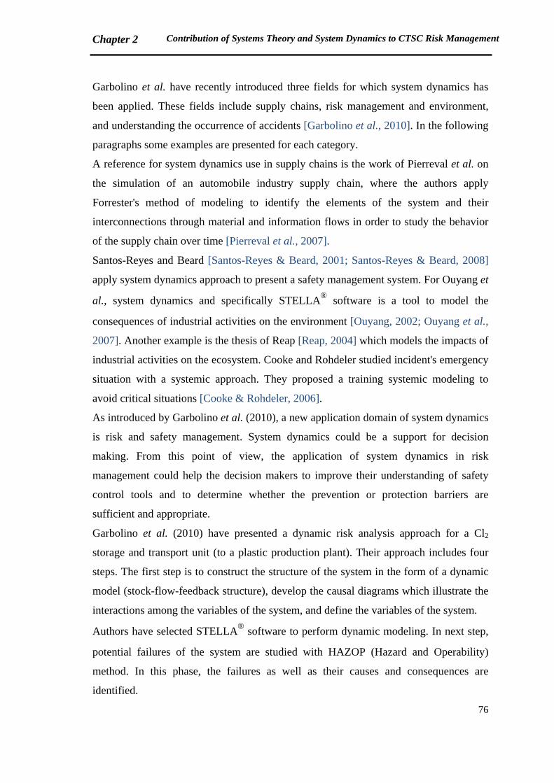
Chapter 2 Contribution of Systems Theory and System Dynamics to CTSC Risk Management
76
Garbolino et al. have recently introduced three fields for which system dynamics has
been applied. These fields include supply chains, risk management and environment,
and understanding the occurrence of accidents [Garbolino et al., 2010]. In the following
paragraphs some examples are presented for each category.
A reference for system dynamics use in supply chains is the work of Pierreval et al. on
the simulation of an automobile industry supply chain, where the authors apply
Forrester's method of modeling to identify the elements of the system and their
interconnections through material and information flows in order to study the behavior
of the supply chain over time [Pierreval et al., 2007].
Santos-Reyes and Beard [Santos-Reyes & Beard, 2001; Santos-Reyes & Beard, 2008]
apply system dynamics approach to present a safety management system. For Ouyang et
al., system dynamics and specifically STELLA® software is a tool to model the
consequences of industrial activities on the environment [Ouyang, 2002; Ouyang et al.,
2007]. Another example is the thesis of Reap [Reap, 2004] which models the impacts of
industrial activities on the ecosystem. Cooke and Rohdeler studied incident's emergency
situation with a systemic approach. They proposed a training systemic modeling to
avoid critical situations [Cooke & Rohdeler, 2006].
As introduced by Garbolino et al. (2010), a new application domain of system dynamics
is risk and safety management. System dynamics could be a support for decision
making. From this point of view, the application of system dynamics in risk
management could help the decision makers to improve their understanding of safety
control tools and to determine whether the prevention or protection barriers are
sufficient and appropriate.
Garbolino et al. (2010) have presented a dynamic risk analysis approach for a Cl2
storage and transport unit (to a plastic production plant). Their approach includes four
steps. The first step is to construct the structure of the system in the form of a dynamic
model (stock-flow-feedback structure), develop the causal diagrams which illustrate the
interactions among the variables of the system, and define the variables of the system.
Authors have selected STELLA® software to perform dynamic modeling. In next step,
potential failures of the system are studied with HAZOP (Hazard and Operability)
method. In this phase, the failures as well as their causes and consequences are
identified.
Chapter 2 Contribution of Systems Theory and System Dynamics to CTSC Risk Management
77
Afterwards, the failure consequences are modeled. The PHAST software is applied for
this purpose to evaluate the effects of failures like toxic waste and overpressure on
human beings and equipment. Finally, they go back to dynamic modeling environment
in order to evaluate whether the available prevention and protection barriers are
efficient. If not, new barriers could be recommended to be added in the system. Their
approach is summarized in Figure 2.7.
Figure 2.7: General steps of dynamic risk analysis for an industrial plant [Garbolino et al., 2010]
As previously mentioned in Chapter 1, section 1.5.2, systemic accident models are the
latest generation of accident models, which give prominence to the dynamic and
nonlinear characteristics of systems. STAMP (Systems-Theoretic Accident Model and
Processes) model, developed by Nancy Leveson at MIT (Massachusetts Institute of
Technology), is one example already introduced in section 1.5.2.
Leveson affirms that to prevent accidents in complex systems we require using accident
models that include social system as well as the technology and its underlying science.
STAMP accident model is created based on the idea which had been previously
proposed by Rasmussen in 1997 [Leveson, 2004a]. Rasmussen argues that complex
sociotechnical systems have been usually modeled by decomposition into separate
components [Rasmussen, 1997]. Decomposition is possible if we ignore the interactions
of components, and the associated feedback network.
Development of the model and simulation of system behavior
Dynamic Risk Analysis with an appropriate method (such as HAZOP)
Simulation of the consequences of failures like toxic waste
Evaluate the efficacy of prevention and protection tools
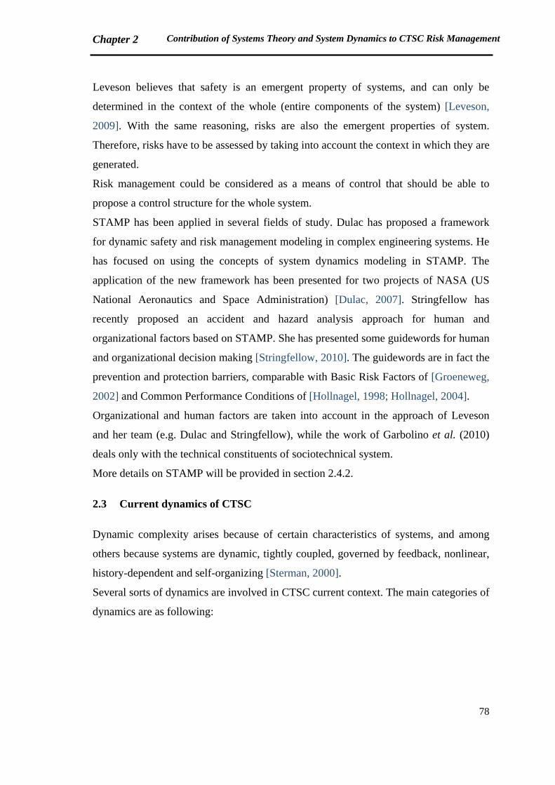
Chapter 2 Contribution of Systems Theory and System Dynamics to CTSC Risk Management
78
Leveson believes that safety is an emergent property of systems, and can only be
determined in the context of the whole (entire components of the system) [Leveson,
2009]. With the same reasoning, risks are also the emergent properties of system.
Therefore, risks have to be assessed by taking into account the context in which they are
generated.
Risk management could be considered as a means of control that should be able to
propose a control structure for the whole system.
STAMP has been applied in several fields of study. Dulac has proposed a framework
for dynamic safety and risk management modeling in complex engineering systems. He
has focused on using the concepts of system dynamics modeling in STAMP. The
application of the new framework has been presented for two projects of NASA (US
National Aeronautics and Space Administration) [Dulac, 2007]. Stringfellow has
recently proposed an accident and hazard analysis approach for human and
organizational factors based on STAMP. She has presented some guidewords for human
and organizational decision making [Stringfellow, 2010]. The guidewords are in fact the
prevention and protection barriers, comparable with Basic Risk Factors of [Groeneweg,
2002] and Common Performance Conditions of [Hollnagel, 1998; Hollnagel, 2004].
Organizational and human factors are taken into account in the approach of Leveson
and her team (e.g. Dulac and Stringfellow), while the work of Garbolino et al. (2010)
deals only with the technical constituents of sociotechnical system.
More details on STAMP will be provided in section 2.4.2.
2.3 Current dynamics of CTSC
Dynamic complexity arises because of certain characteristics of systems, and among
others because systems are dynamic, tightly coupled, governed by feedback, nonlinear,
history-dependent and self-organizing [Sterman, 2000].
Several sorts of dynamics are involved in CTSC current context. The main categories of
dynamics are as following:
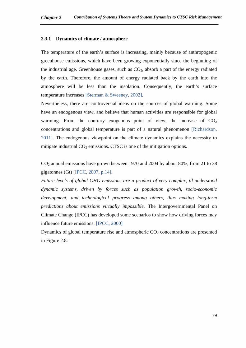
Chapter 2 Contribution of Systems Theory and System Dynamics to CTSC Risk Management
79
2.3.1 Dynamics of climate / atmosphere
The temperature of the earth’s surface is increasing, mainly because of anthropogenic
greenhouse emissions, which have been growing exponentially since the beginning of
the industrial age. Greenhouse gases, such as CO2, absorb a part of the energy radiated
by the earth. Therefore, the amount of energy radiated back by the earth into the
atmosphere will be less than the insolation. Consequently, the earth’s surface
temperature increases [Sterman & Sweeney, 2002].
Nevertheless, there are controversial ideas on the sources of global warming. Some
have an endogenous view, and believe that human activities are responsible for global
warming. From the contrary exogenous point of view, the increase of CO2
concentrations and global temperature is part of a natural phenomenon [Richardson,
2011]. The endogenous viewpoint on the climate dynamics explains the necessity to
mitigate industrial CO2 emissions. CTSC is one of the mitigation options.
CO2 annual emissions have grown between 1970 and 2004 by about 80%, from 21 to 38
gigatonnes (Gt) [IPCC, 2007, p.14].
Future levels of global GHG emissions are a product of very complex, ill-understood
dynamic systems, driven by forces such as population growth, socio-economic
development, and technological progress among others, thus making long-term
predictions about emissions virtually impossible. The Intergovernmental Panel on
Climate Change (IPCC) has developed some scenarios to show how driving forces may
influence future emissions. [IPCC, 2000]
Dynamics of global temperature rise and atmospheric CO2 concentrations are presented
in Figure 2.8:
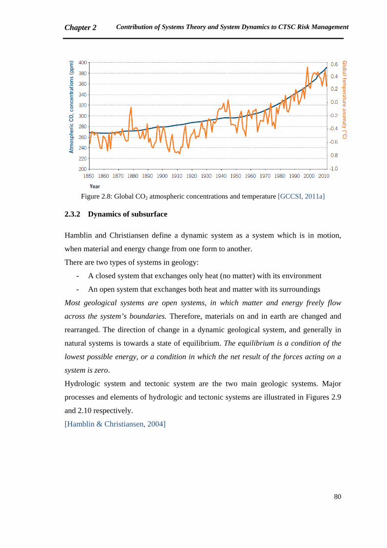
Chapter 2 Contribution of Systems Theory and System Dynamics to CTSC Risk Management
80
Figure 2.8: Global CO2 atmospheric concentrations and temperature [GCCSI, 2011a]
2.3.2 Dynamics of subsurface
Hamblin and Christiansen define a dynamic system as a system which is in motion,
when material and energy change from one form to another.
There are two types of systems in geology:
- A closed system that exchanges only heat (no matter) with its environment
- An open system that exchanges both heat and matter with its surroundings
Most geological systems are open systems, in which matter and energy freely flow
across the system’s boundaries. Therefore, materials on and in earth are changed and
rearranged. The direction of change in a dynamic geological system, and generally in
natural systems is towards a state of equilibrium. The equilibrium is a condition of the
lowest possible energy, or a condition in which the net result of the forces acting on a
system is zero.
Hydrologic system and tectonic system are the two main geologic systems. Major
processes and elements of hydrologic and tectonic systems are illustrated in Figures 2.9
and 2.10 respectively.
[Hamblin & Christiansen, 2004]
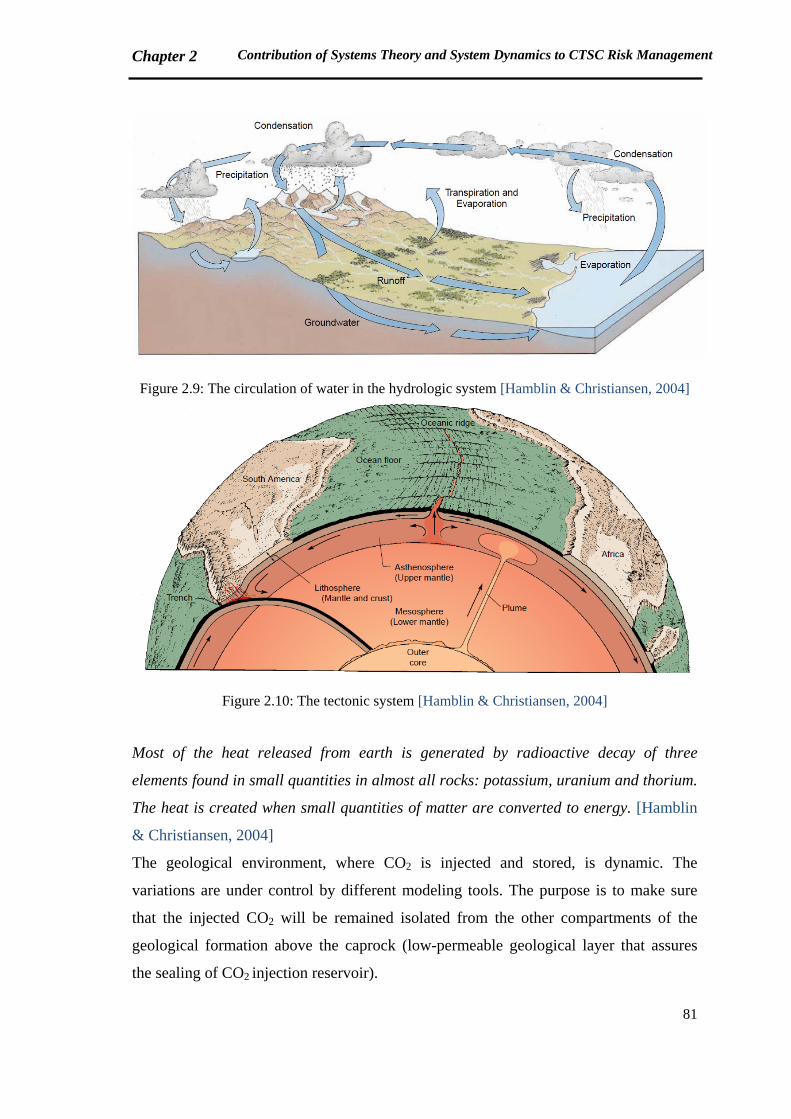
Chapter 2 Contribution of Systems Theory and System Dynamics to CTSC Risk Management
81
Figure 2.9: The circulation of water in the hydrologic system [Hamblin & Christiansen, 2004]
Figure 2.10: The tectonic system [Hamblin & Christiansen, 2004]
Most of the heat released from earth is generated by radioactive decay of three
elements found in small quantities in almost all rocks: potassium, uranium and thorium.
The heat is created when small quantities of matter are converted to energy. [Hamblin
& Christiansen, 2004]
The geological environment, where CO2 is injected and stored, is dynamic. The
variations are under control by different modeling tools. The purpose is to make sure
that the injected CO2 will be remained isolated from the other compartments of the
geological formation above the caprock (low-permeable geological layer that assures
the sealing of CO2 injection reservoir).
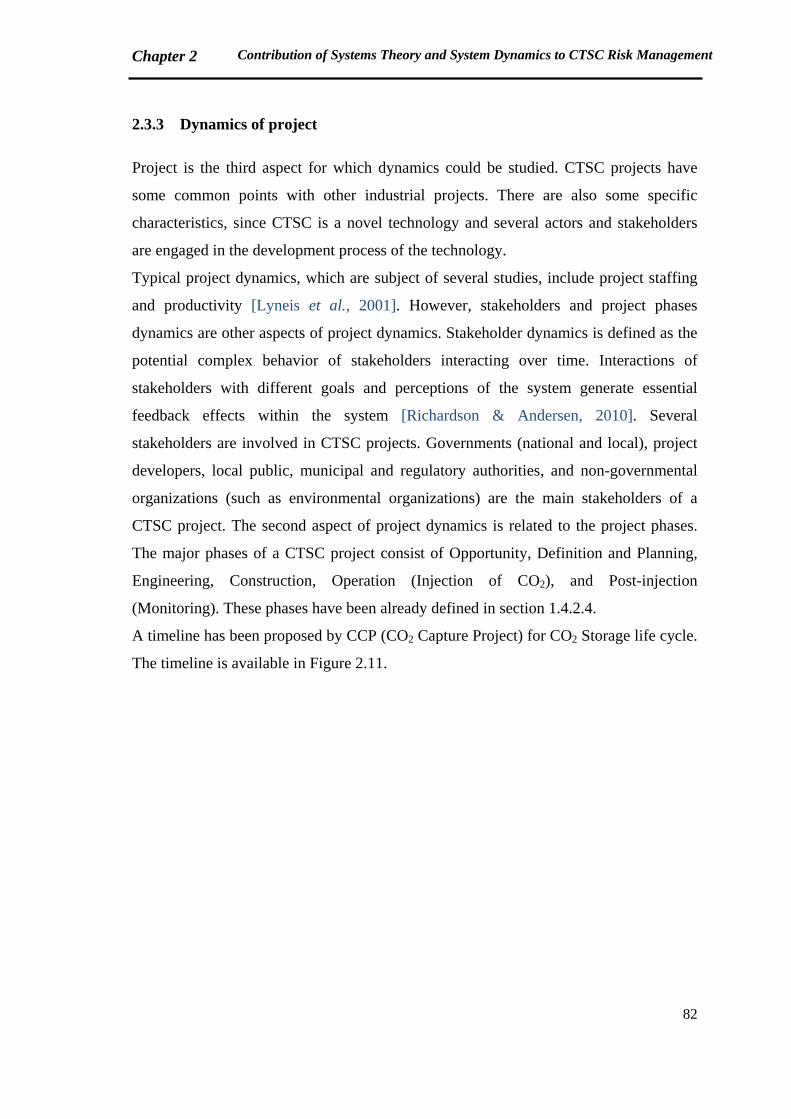
Chapter 2 Contribution of Systems Theory and System Dynamics to CTSC Risk Management
82
2.3.3 Dynamics of project
Project is the third aspect for which dynamics could be studied. CTSC projects have
some common points with other industrial projects. There are also some specific
characteristics, since CTSC is a novel technology and several actors and stakeholders
are engaged in the development process of the technology.
Typical project dynamics, which are subject of several studies, include project staffing
and productivity [Lyneis et al., 2001]. However, stakeholders and project phases
dynamics are other aspects of project dynamics. Stakeholder dynamics is defined as the
potential complex behavior of stakeholders interacting over time. Interactions of
stakeholders with different goals and perceptions of the system generate essential
feedback effects within the system [Richardson & Andersen, 2010]. Several
stakeholders are involved in CTSC projects. Governments (national and local), project
developers, local public, municipal and regulatory authorities, and non-governmental
organizations (such as environmental organizations) are the main stakeholders of a
CTSC project. The second aspect of project dynamics is related to the project phases.
The major phases of a CTSC project consist of Opportunity, Definition and Planning,
Engineering, Construction, Operation (Injection of CO2), and Post-injection
(Monitoring). These phases have been already defined in section 1.4.2.4.
A timeline has been proposed by CCP (CO2 Capture Project) for CO2 Storage life cycle.
The timeline is available in Figure 2.11.
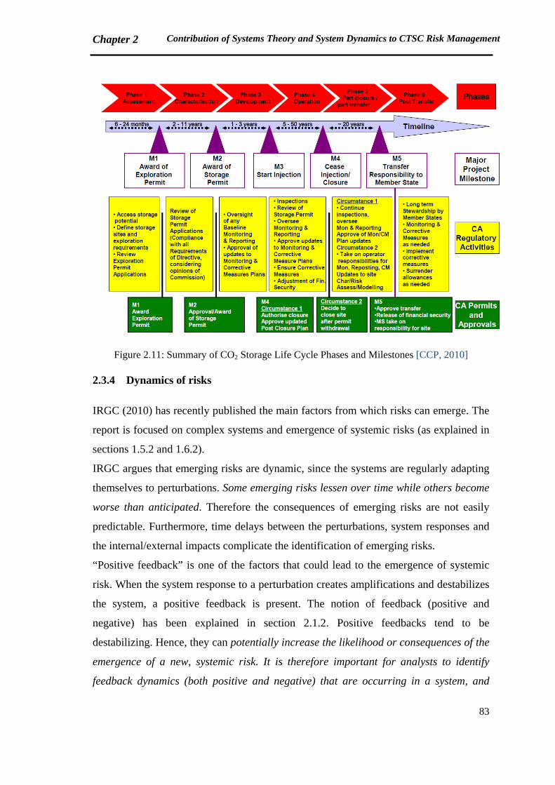
Chapter 2 Contribution of Systems Theory and System Dynamics to CTSC Risk Management
83
Figure 2.11: Summary of CO2 Storage Life Cycle Phases and Milestones [CCP, 2010]
2.3.4 Dynamics of risks
IRGC (2010) has recently published the main factors from which risks can emerge. The
report is focused on complex systems and emergence of systemic risks (as explained in
sections 1.5.2 and 1.6.2).
IRGC argues that emerging risks are dynamic, since the systems are regularly adapting
themselves to perturbations. Some emerging risks lessen over time while others become
worse than anticipated. Therefore the consequences of emerging risks are not easily
predictable. Furthermore, time delays between the perturbations, system responses and
the internal/external impacts complicate the identification of emerging risks.
“Positive feedback” is one of the factors that could lead to the emergence of systemic
risk. When the system response to a perturbation creates amplifications and destabilizes
the system, a positive feedback is present. The notion of feedback (positive and
negative) has been explained in section 2.1.2. Positive feedbacks tend to be
destabilizing. Hence, they can potentially increase the likelihood or consequences of the
emergence of a new, systemic risk. It is therefore important for analysts to identify
feedback dynamics (both positive and negative) that are occurring in a system, and
Chapter 2 Contribution of Systems Theory and System Dynamics to CTSC Risk Management
84
assess their function and their relative balance (if their positive or negative dominate)
in order to better anticipate when risks might emerge or be amplified. [IRGC, 2010]
Rodrigues believes that risks are dynamic events. Risk dynamics are generated by a
network of feedback loops in the project. He affirms that the management needs to have
a systemic view to understand why risks emerge, because risks have a systemic nature
[Rodrigues, 2001].
Current dynamics of CTSC were reviewed in this section. In the next part we will
discuss how these dynamics could be studied and analyzed using systemic approaches.
2.4 Contribution of Systemic Approaches and System Dynamics to study the
dynamics of CTSC
CTSC is a complex sociotechnical system, including three technical components of
Capture, Transport and Storage, and an organization structure containing a group of
actors [Samadi & Garbolino, 2011].
Available lessons learned from CTSC projects confirm that the feedback loops of
different types of risk are significant in the development process of projects. Technical
aspects of long-term safety of CO2 storage have been always at the heart of risk
assessment studies. However, technical risks are continually in inter-relation with other
aspects of risk.
At the present time, the main question about CTSC is whether the technology will be
developed progressively up to commercial scales. According to the available statistics
on CTSC projects all around the world, only fourteen large scale integrated projects are
currently in operation or construction. The other sixty projects are under identification
or finalization of scopes and execution plans [GCCSI, 2011a]. (refer to Figure 1.3)
In the current thesis, we focus on modeling risks of CTSC projects development using a
systemic approach. In other words, dynamics of project and risks are under study.
The question is how dynamics of risks affect dynamics of CTSC projects, and how
interconnections of stakeholders and associated risks could result in the success or
failure of a CTSC project progress. If we rephrase the goal in system dynamics
language, the problem we are modeling is that some particular CTSC projects are not
successful to be developed.
Chapter 2 Contribution of Systems Theory and System Dynamics to CTSC Risk Management
85
Lyneis and Ford mention four groups of project structures for which system dynamics
has been applied. The structures include:
- Project features (development processes, resources, managerial mental models and
decision making)
- Rework cycle
- Project control
- Ripple effects (such as fatigue, communication difficulties, and experience) and
knock-on effects (such as hopelessness and morale problems) [Lyneis & Ford, 2007]
A methodology is developed based on STAMP approach to model the structure of
safety control in CTSC projects, and analyze the feedback network dynamics of CTSC
project risks.
To understand how STAMP, as a systemic approach, could contribute to study the risks
of CTSC projects, we will firstly recall an overall view of risk and safety management
approaches development in section 2.4.1. Details and examples of STAMP will be
presented in section 2.4.2.
2.4.1 Evolution of risk / safety management approaches
As previously explained in Chapter 1, traditional risk analysis methods are based on
sequential accident models, and therefore not appropriate for sociotechnical complex
systems.
Safety management approaches have evolved based on the lessons learned from
industrial accidents (Figure 2.12).
Until 1950s-1960s, safety was considered as a technical problem. Therefore, safety
management was based on the improvement of technical systems reliability. From
1960s, technical issues were not sufficient to explain the accidents. Human errors are
then brought in safety management approaches. By mid 1980s, lessons learned from
industrial disasters such as Three Miles Island, Bhopal, Chernobyl and Challenger,
highlighted the incomprehensiveness of human errors for analyzing accidents.
According to Cambon, the lessons learned affirm that human errors could not be
disconnected from the organizational context in which they had been generated. Hence,
in 1980s-1990s, the human error is recognized as a consequence of the organizational
problems. Cambon explains that the organizational approaches are characterized to be
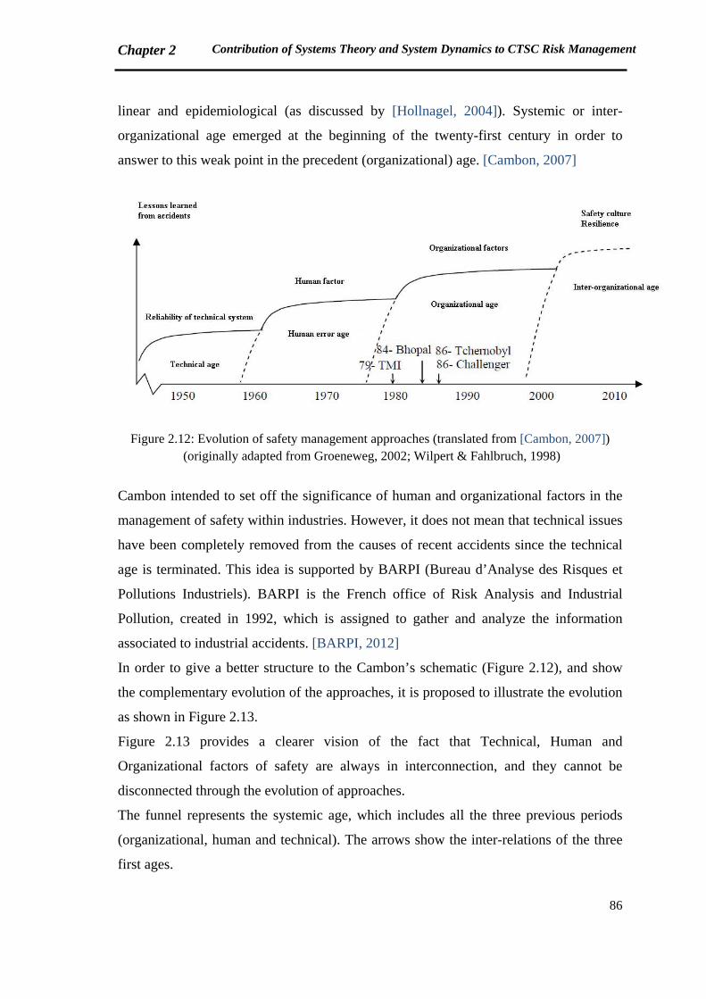
Chapter 2 Contribution of Systems Theory and System Dynamics to CTSC Risk Management
86
linear and epidemiological (as discussed by [Hollnagel, 2004]). Systemic or inter-
organizational age emerged at the beginning of the twenty-first century in order to
answer to this weak point in the precedent (organizational) age. [Cambon, 2007]
Figure 2.12: Evolution of safety management approaches (translated from [Cambon, 2007]) (originally adapted from Groeneweg, 2002; Wilpert & Fahlbruch, 1998)
Cambon intended to set off the significance of human and organizational factors in the
management of safety within industries. However, it does not mean that technical issues
have been completely removed from the causes of recent accidents since the technical
age is terminated. This idea is supported by BARPI (Bureau d’Analyse des Risques et
Pollutions Industriels). BARPI is the French office of Risk Analysis and Industrial
Pollution, created in 1992, which is assigned to gather and analyze the information
associated to industrial accidents. [BARPI, 2012]
In order to give a better structure to the Cambon’s schematic (Figure 2.12), and show
the complementary evolution of the approaches, it is proposed to illustrate the evolution
as shown in Figure 2.13.
Figure 2.13 provides a clearer vision of the fact that Technical, Human and
Organizational factors of safety are always in interconnection, and they cannot be
disconnected through the evolution of approaches.
The funnel represents the systemic age, which includes all the three previous periods
(organizational, human and technical). The arrows show the inter-relations of the three
first ages.
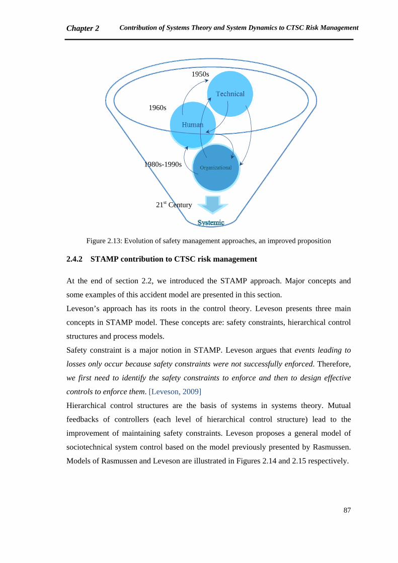
Chapter 2 Contribution of Systems Theory and System Dynamics to CTSC Risk Management
87
Figure 2.13: Evolution of safety management approaches, an improved proposition
2.4.2 STAMP contribution to CTSC risk management
At the end of section 2.2, we introduced the STAMP approach. Major concepts and
some examples of this accident model are presented in this section.
Leveson’s approach has its roots in the control theory. Leveson presents three main
concepts in STAMP model. These concepts are: safety constraints, hierarchical control
structures and process models.
Safety constraint is a major notion in STAMP. Leveson argues that events leading to
losses only occur because safety constraints were not successfully enforced. Therefore,
we first need to identify the safety constraints to enforce and then to design effective
controls to enforce them. [Leveson, 2009]
Hierarchical control structures are the basis of systems in systems theory. Mutual
feedbacks of controllers (each level of hierarchical control structure) lead to the
improvement of maintaining safety constraints. Leveson proposes a general model of
sociotechnical system control based on the model previously presented by Rasmussen.
Models of Rasmussen and Leveson are illustrated in Figures 2.14 and 2.15 respectively.
1950s
1960s
1980s-1990s
21st Century
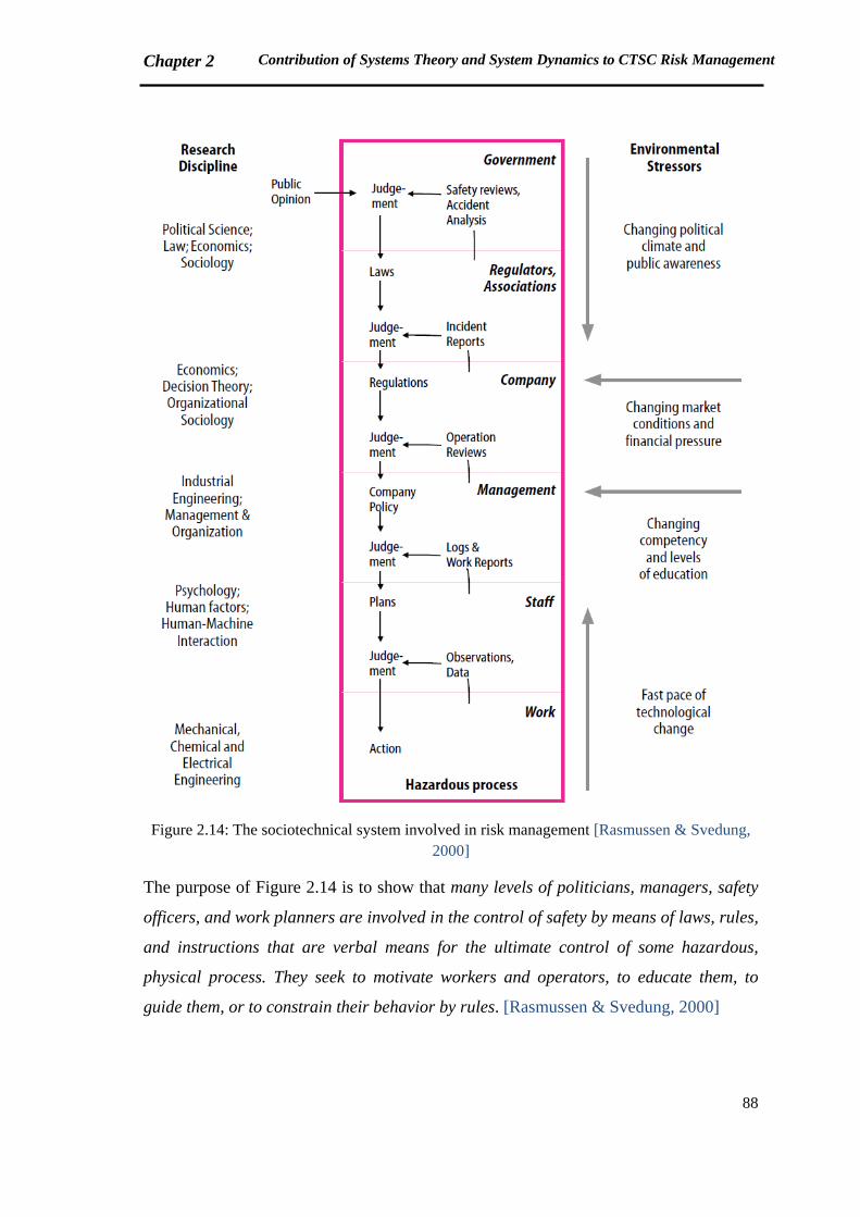
Chapter 2 Contribution of Systems Theory and System Dynamics to CTSC Risk Management
88
Figure 2.14: The sociotechnical system involved in risk management [Rasmussen & Svedung,
2000]
The purpose of Figure 2.14 is to show that many levels of politicians, managers, safety
officers, and work planners are involved in the control of safety by means of laws, rules,
and instructions that are verbal means for the ultimate control of some hazardous,
physical process. They seek to motivate workers and operators, to educate them, to
guide them, or to constrain their behavior by rules. [Rasmussen & Svedung, 2000]
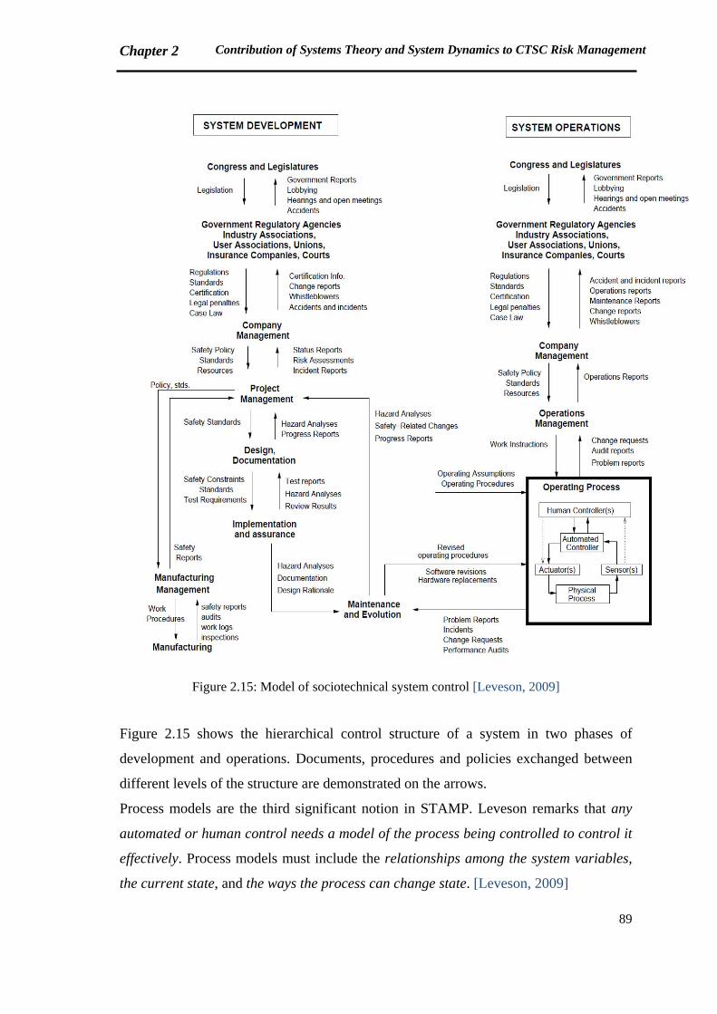
Chapter 2 Contribution of Systems Theory and System Dynamics to CTSC Risk Management
89
Figure 2.15: Model of sociotechnical system control [Leveson, 2009]
Figure 2.15 shows the hierarchical control structure of a system in two phases of
development and operations. Documents, procedures and policies exchanged between
different levels of the structure are demonstrated on the arrows.
Process models are the third significant notion in STAMP. Leveson remarks that any
automated or human control needs a model of the process being controlled to control it
effectively. Process models must include the relationships among the system variables,
the current state, and the ways the process can change state. [Leveson, 2009]
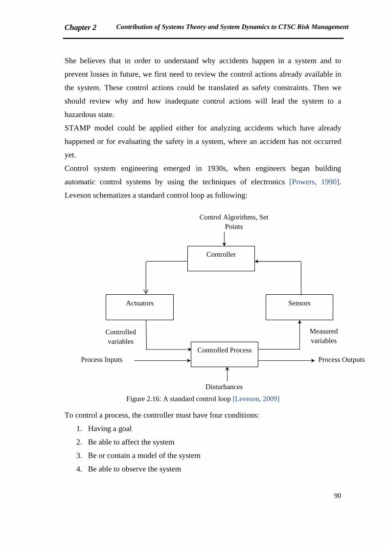
Chapter 2 Contribution of Systems Theory and System Dynamics to CTSC Risk Management
90
She believes that in order to understand why accidents happen in a system and to
prevent losses in future, we first need to review the control actions already available in
the system. These control actions could be translated as safety constraints. Then we
should review why and how inadequate control actions will lead the system to a
hazardous state.
STAMP model could be applied either for analyzing accidents which have already
happened or for evaluating the safety in a system, where an accident has not occurred
yet.
Control system engineering emerged in 1930s, when engineers began building
automatic control systems by using the techniques of electronics [Powers, 1990].
Leveson schematizes a standard control loop as following:
Figure 2.16: A standard control loop [Leveson, 2009]
To control a process, the controller must have four conditions:
1. Having a goal
2. Be able to affect the system
3. Be or contain a model of the system
4. Be able to observe the system
Controller
Actuators Sensors
Controlled Process
Controlled variables
Measured variables
Process Inputs Process Outputs
Disturbances
Control Algorithms, Set Points
Chapter 2 Contribution of Systems Theory and System Dynamics to CTSC Risk Management
91
The controller observes the system by sensors, which obtains the measured variables of
the system. The output of the controller affects the system by providing controlled
variables through actuators. The purpose is to maintain the set point, which is the goal
of the controller [Leveson, 2009].
In the field of our study, the process under control is the progress of CTSC project in a
sustainable manner. The actors or stakeholders of CTSC technology are the controllers.
This idea will be explained in Chapter 3.
In her new book, Leveson clearly explains the steps of applying STAMP model to
analyze accidents [Leveson, 2009]:
- First of all, we should find out the events leading to the loss. It means that we simply
list all the chain of events contributing in the occurrence of that accident.
- Secondly, the hazards and system boundaries should be identified.
- The next step is to find out the system safety constraints and system requirements
regarding each hazard.
- Then, we should form the hierarchical structure of safety control for the system. The
roles and responsibilities of each actor (controller) should be clearly defined in this
structure.
- After that, the losses of physical system level should be analyzed. Four principal
categories of information are required in this analysis including: safety requirements
and constraints, existing controls, failures and inadequate controls, and the context.
- The sixth step is to analyze the hierarchical levels of safety control structure. In this
stage, we need to collect four groups of information for each actor: safety-related
responsibilities, context, unsafe decisions and control actions, and process model
flaws.
- In the next step, the coordination and communication between actors (controllers)
will be studied.
- Subsequently, we should study the dynamics (changes over time) relating to the loss.
- The final step is to offer recommendations to prevent similar accidents in future.
By now, this approach has been made in application for several examples. One of these
examples which could be helpful to better understand the steps of an accident analysis
by STAMP model, is an accident at a chemical plant called Citichem. This accident
Chapter 2 Contribution of Systems Theory and System Dynamics to CTSC Risk Management
92
happened in Oakbridge, US, as a result of a chemical reaction between a chemical
called K34 and water, entered to K34 storage tank via raining. The reaction leads to the
release of a toxic gas, Tetra Chloric Cyanide (TCC) which is flammable, corrosive and
volatile. 400 people were killed in this accident. Application of STAMP for analyzing
this accident is presented in the subsequent paragraphs [Leveson, 2009]:
- The first step is to list the chain of events leading to the disaster.
- At the second stage, two systems are identified in Citichem, the chemical company
and Oakbridge community, which is responsible to protect public health (refer to
Figure 2.17 for a schematic view of these systems).
The major components of each system and their interactions as well as the
boundaries of systems are identified. And then the hazards associated with each
system are found out. In this case, release of toxic chemicals and exposure of the
public to toxic chemicals are the related hazards for the chemical plant and the public
health structure, respectively.
- The third step is to develop the safety control structure for these two systems. To
determine the components of each structure, safety-related requirements are firstly
listed for each system (chemical plant and the community).
- Subsequently, the analysis starts with the plant physical safety controls. As explained
before, in this part we should define safety requirements, safety controls which have
existed, inadequate controls concerning physical plant and associated contextual
facts.
At each stage of the analysis, recommendations can be provided to avoid inadequate
safety controls.
- The analysis continues with structuring the hierarchical levels of safety control.
Leveson has put some examples of these structures for several actors (controllers)
such as maintenance worker, maintenance manager, operations manager, plant
manager, corporate management, Oakbridge emergency response system, Oakbridge
government and local residents. In each box, related to each actor (controller), his
safety related responsibilities, the actual context in which he works or lives, his
unsafe decisions and control actions and finally his process model defects (flaws) are
listed.
At the end of this part, recommendations could be provided based on the analysis.
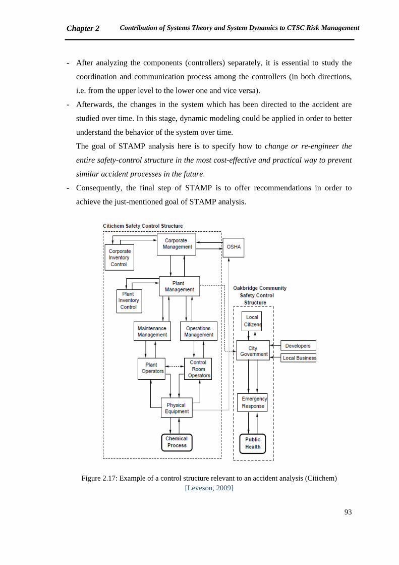
Chapter 2 Contribution of Systems Theory and System Dynamics to CTSC Risk Management
93
- After analyzing the components (controllers) separately, it is essential to study the
coordination and communication process among the controllers (in both directions,
i.e. from the upper level to the lower one and vice versa).
- Afterwards, the changes in the system which has been directed to the accident are
studied over time. In this stage, dynamic modeling could be applied in order to better
understand the behavior of the system over time.
The goal of STAMP analysis here is to specify how to change or re-engineer the
entire safety-control structure in the most cost-effective and practical way to prevent
similar accident processes in the future.
- Consequently, the final step of STAMP is to offer recommendations in order to
achieve the just-mentioned goal of STAMP analysis.
Figure 2.17: Example of a control structure relevant to an accident analysis (Citichem) [Leveson, 2009]
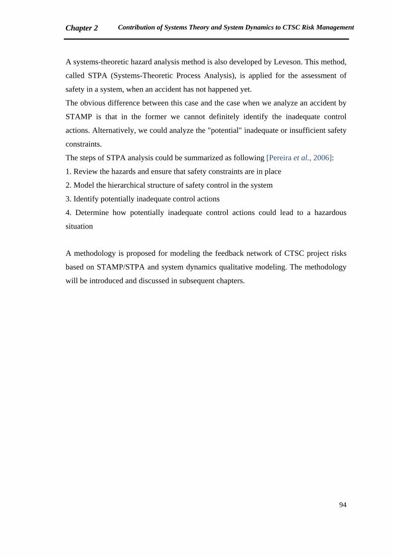
Chapter 2 Contribution of Systems Theory and System Dynamics to CTSC Risk Management
94
A systems-theoretic hazard analysis method is also developed by Leveson. This method,
called STPA (Systems-Theoretic Process Analysis), is applied for the assessment of
safety in a system, when an accident has not happened yet.
The obvious difference between this case and the case when we analyze an accident by
STAMP is that in the former we cannot definitely identify the inadequate control
actions. Alternatively, we could analyze the "potential" inadequate or insufficient safety
constraints.
The steps of STPA analysis could be summarized as following [Pereira et al., 2006]:
1. Review the hazards and ensure that safety constraints are in place
2. Model the hierarchical structure of safety control in the system
3. Identify potentially inadequate control actions
4. Determine how potentially inadequate control actions could lead to a hazardous
situation
A methodology is proposed for modeling the feedback network of CTSC project risks
based on STAMP/STPA and system dynamics qualitative modeling. The methodology
will be introduced and discussed in subsequent chapters.
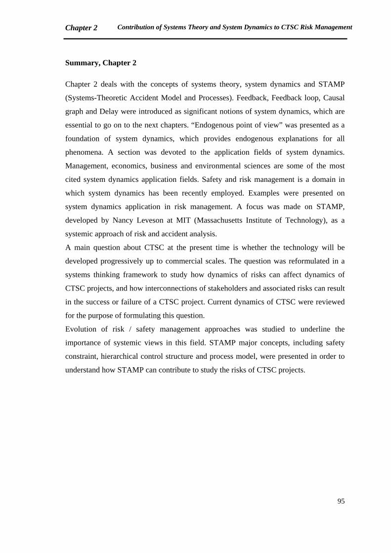
Chapter 2 Contribution of Systems Theory and System Dynamics to CTSC Risk Management
95
Summary, Chapter 2
Chapter 2 deals with the concepts of systems theory, system dynamics and STAMP
(Systems-Theoretic Accident Model and Processes). Feedback, Feedback loop, Causal
graph and Delay were introduced as significant notions of system dynamics, which are
essential to go on to the next chapters. “Endogenous point of view” was presented as a
foundation of system dynamics, which provides endogenous explanations for all
phenomena. A section was devoted to the application fields of system dynamics.
Management, economics, business and environmental sciences are some of the most
cited system dynamics application fields. Safety and risk management is a domain in
which system dynamics has been recently employed. Examples were presented on
system dynamics application in risk management. A focus was made on STAMP,
developed by Nancy Leveson at MIT (Massachusetts Institute of Technology), as a
systemic approach of risk and accident analysis.
A main question about CTSC at the present time is whether the technology will be
developed progressively up to commercial scales. The question was reformulated in a
systems thinking framework to study how dynamics of risks can affect dynamics of
CTSC projects, and how interconnections of stakeholders and associated risks can result
in the success or failure of a CTSC project. Current dynamics of CTSC were reviewed
for the purpose of formulating this question.
Evolution of risk / safety management approaches was studied to underline the
importance of systemic views in this field. STAMP major concepts, including safety
constraint, hierarchical control structure and process model, were presented in order to
understand how STAMP can contribute to study the risks of CTSC projects.
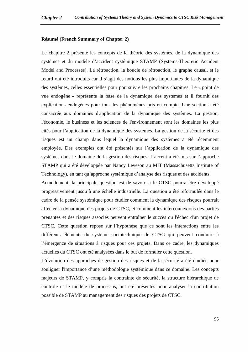
Chapter 2 Contribution of Systems Theory and System Dynamics to CTSC Risk Management
96
Résumé (French Summary of Chapter 2)
Le chapitre 2 présente les concepts de la théorie des systèmes, de la dynamique des
systèmes et du modèle d’accident systémique STAMP (Systems-Theoretic Accident
Model and Processes). La rétroaction, la boucle de rétroaction, le graphe causal, et le
retard ont été introduits car il s’agit des notions les plus importantes de la dynamique
des systèmes, celles essentielles pour poursuivre les prochains chapitres. Le « point de
vue endogène » représente la base de la dynamique des systèmes et il fournit des
explications endogènes pour tous les phénomènes pris en compte. Une section a été
consacrée aux domaines d'application de la dynamique des systèmes. La gestion,
l'économie, le business et les sciences de l'environnement sont les domaines les plus
cités pour l’application de la dynamique des systèmes. La gestion de la sécurité et des
risques est un champ dans lequel la dynamique des systèmes a été récemment
employée. Des exemples ont été présentés sur l’application de la dynamique des
systèmes dans le domaine de la gestion des risques. L'accent a été mis sur l’approche
STAMP qui a été développée par Nancy Leveson au MIT (Massachusetts Institute of
Technology), en tant qu’approche systémique d’analyse des risques et des accidents.
Actuellement, la principale question est de savoir si le CTSC pourra être développé
progressivement jusqu’à une échelle industrielle. La question a été reformulée dans le
cadre de la pensée systémique pour étudier comment la dynamique des risques pourrait
affecter la dynamique des projets de CTSC, et comment les interconnexions des parties
prenantes et des risques associés peuvent entraîner le succès ou l'échec d'un projet de
CTSC. Cette question repose sur l’hypothèse que ce sont les interactions entre les
différents éléments du système sociotechnique de CTSC qui peuvent conduire à
l’émergence de situations à risques pour ces projets. Dans ce cadre, les dynamiques
actuelles du CTSC ont été analysées dans le but de formuler cette question.
L’évolution des approches de gestion des risques et de la sécurité a été étudiée pour
souligner l'importance d’une méthodologie systémique dans ce domaine. Les concepts
majeurs de STAMP, y compris la contrainte de sécurité, la structure hiérarchique de
contrôle et le modèle de processus, ont été présentés pour analyser la contribution
possible de STAMP au management des risques des projets de CTSC.

97
Chapter 3: Proposed Systemic Methodology for Risk Management of CTSC projects
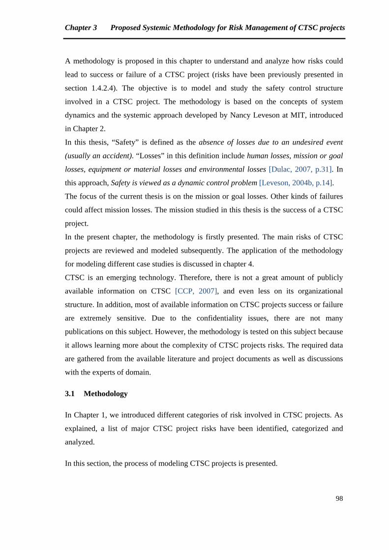
Chapter 3 Proposed Systemic Methodology for Risk Management of CTSC projects
98
A methodology is proposed in this chapter to understand and analyze how risks could
lead to success or failure of a CTSC project (risks have been previously presented in
section 1.4.2.4). The objective is to model and study the safety control structure
involved in a CTSC project. The methodology is based on the concepts of system
dynamics and the systemic approach developed by Nancy Leveson at MIT, introduced
in Chapter 2.
In this thesis, “Safety” is defined as the absence of losses due to an undesired event
(usually an accident). “Losses” in this definition include human losses, mission or goal
losses, equipment or material losses and environmental losses [Dulac, 2007, p.31]. In
this approach, Safety is viewed as a dynamic control problem [Leveson, 2004b, p.14].
The focus of the current thesis is on the mission or goal losses. Other kinds of failures
could affect mission losses. The mission studied in this thesis is the success of a CTSC
project.
In the present chapter, the methodology is firstly presented. The main risks of CTSC
projects are reviewed and modeled subsequently. The application of the methodology
for modeling different case studies is discussed in chapter 4.
CTSC is an emerging technology. Therefore, there is not a great amount of publicly
available information on CTSC [CCP, 2007], and even less on its organizational
structure. In addition, most of available information on CTSC projects success or failure
are extremely sensitive. Due to the confidentiality issues, there are not many
publications on this subject. However, the methodology is tested on this subject because
it allows learning more about the complexity of CTSC projects risks. The required data
are gathered from the available literature and project documents as well as discussions
with the experts of domain.
3.1 Methodology
In Chapter 1, we introduced different categories of risk involved in CTSC projects. As
explained, a list of major CTSC project risks have been identified, categorized and
analyzed.
In this section, the process of modeling CTSC projects is presented.

Chapter 3 Proposed Systemic Methodology for Risk Management of CTSC projects
99
3.1.1 Overview of the proposed methodology
The following algorithm (Figure 3.1) summarizes the steps of what was carried out in
order to study safety control structure of CTSC projects. The five first steps are
explained in the current chapter. The final step will be discussed in chapter 4. The
purpose is to analyze the factors which make a CTSC project successful and the risks
that prevent the project development.
Figure 3.1: Proposed methodology steps
A list of thirty nine major risks are identified after reviewing several references
[GCCSI, 2009a; GCCSI, 2011a; Longannet, 2011; Feenstra et al. 2010; Kerlero de
Rosbo, 2009; CCP, 2007; Lacq Project, 2012]. The list is available in Table 3.1.
Table 3.1
Table 3.2
Table 3.3
Table 3.4
Sections 3.1.2 & 3.2
Chapter 4
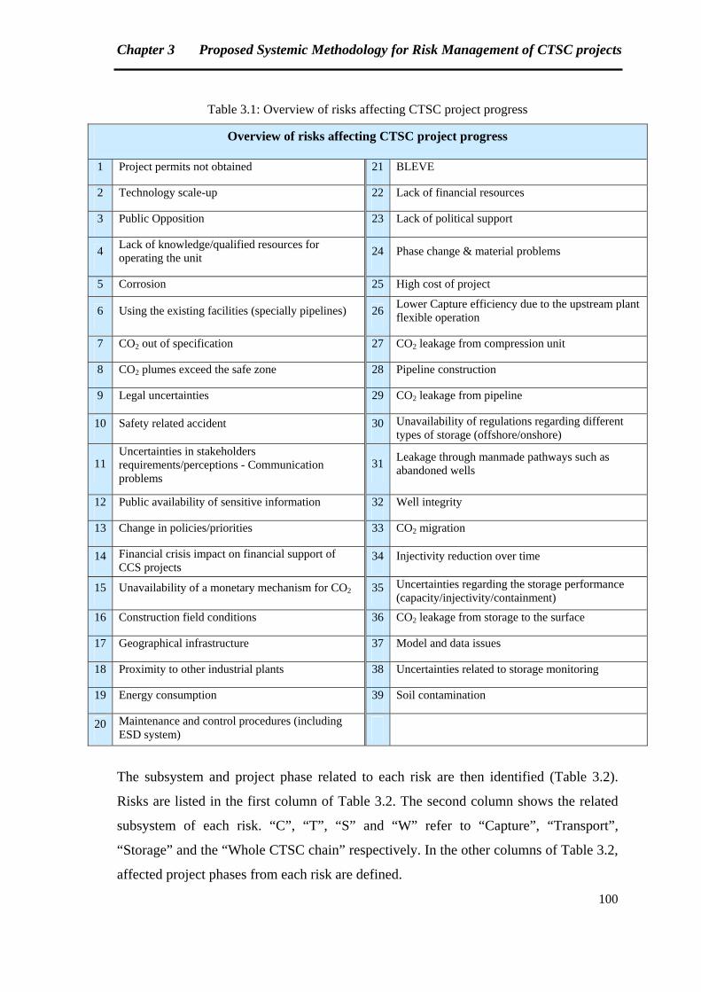
Chapter 3 Proposed Systemic Methodology for Risk Management of CTSC projects
100
Table 3.1: Overview of risks affecting CTSC project progress
Overview of risks affecting CTSC project progress
1 Project permits not obtained 21 BLEVE
2 Technology scale-up 22 Lack of financial resources
3 Public Opposition 23 Lack of political support
4 Lack of knowledge/qualified resources for operating the unit
24 Phase change & material problems
5 Corrosion 25 High cost of project
6 Using the existing facilities (specially pipelines) 26 Lower Capture efficiency due to the upstream plant flexible operation
7 CO2 out of specification 27 CO2 leakage from compression unit
8 CO2 plumes exceed the safe zone 28 Pipeline construction
9 Legal uncertainties 29 CO2 leakage from pipeline
10 Safety related accident 30 Unavailability of regulations regarding different types of storage (offshore/onshore)
11 Uncertainties in stakeholders requirements/perceptions - Communication problems
31 Leakage through manmade pathways such as abandoned wells
12 Public availability of sensitive information 32 Well integrity
13 Change in policies/priorities 33 CO2 migration
14 Financial crisis impact on financial support of CCS projects
34 Injectivity reduction over time
15 Unavailability of a monetary mechanism for CO2 35 Uncertainties regarding the storage performance (capacity/injectivity/containment)
16 Construction field conditions 36 CO2 leakage from storage to the surface
17 Geographical infrastructure 37 Model and data issues
18 Proximity to other industrial plants 38 Uncertainties related to storage monitoring
19 Energy consumption 39 Soil contamination
20 Maintenance and control procedures (including ESD system)
The subsystem and project phase related to each risk are then identified (Table 3.2).
Risks are listed in the first column of Table 3.2. The second column shows the related
subsystem of each risk. “C”, “T”, “S” and “W” refer to “Capture”, “Transport”,
“Storage” and the “Whole CTSC chain” respectively. In the other columns of Table 3.2,
affected project phases from each risk are defined.
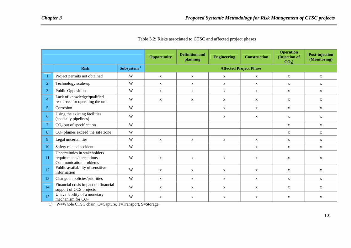
Chapter 3 Proposed Systemic Methodology for Risk Management of CTSC projects
101
Table 3.2: Risks associated to CTSC and affected project phases
Opportunity Definition and
planning Engineering Construction
Operation (Injection of
CO2)
Post-injection (Monitoring)
Risk Subsystem 1 Affected Project Phase
1 Project permits not obtained W x x x x x x
2 Technology scale-up W x x x x x x
3 Public Opposition W x x x x x x
4 Lack of knowledge/qualified resources for operating the unit
W x x x x x x
5 Corrosion W x x x x
6 Using the existing facilities (specially pipelines)
W x x x x
7 CO2 out of specification W x x
8 CO2 plumes exceed the safe zone W x x
9 Legal uncertainties W x x x x x x
10 Safety related accident W x x x
11 Uncertainties in stakeholders requirements/perceptions -Communication problems
W x x x x x x
12 Public availability of sensitive information
W x x x x x x
13 Change in policies/priorities W x x x x x x
14 Financial crisis impact on financial support of CCS projects
W x x x x x x
15 Unavailability of a monetary mechanism for CO2
W x x x x x x
1) W=Whole CTSC chain, C=Capture, T=Transport, S=Storage
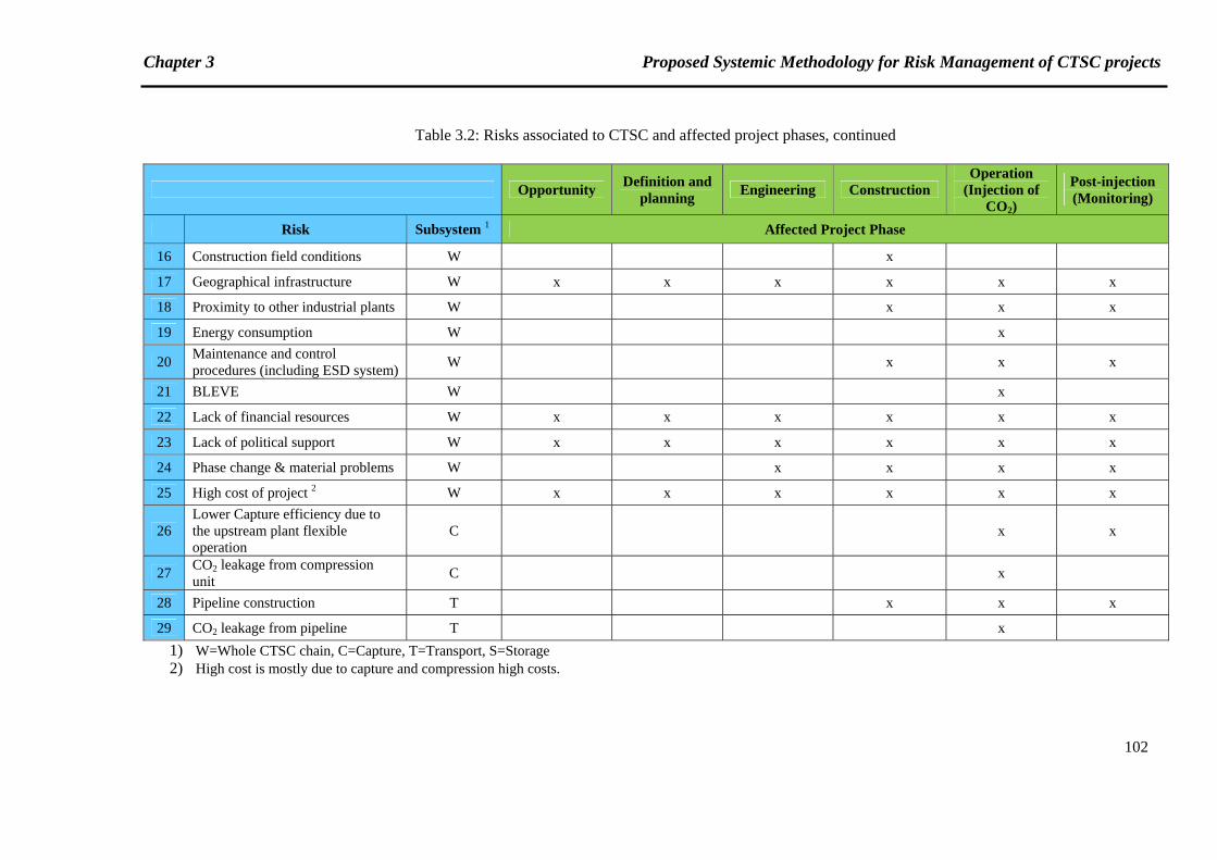
Chapter 3 Proposed Systemic Methodology for Risk Management of CTSC projects
102
Table 3.2: Risks associated to CTSC and affected project phases, continued
Opportunity Definition and
planning Engineering Construction
Operation (Injection of
CO2)
Post-injection (Monitoring)
Risk Subsystem 1 Affected Project Phase
16 Construction field conditions W x
17 Geographical infrastructure W x x x x x x
18 Proximity to other industrial plants W x x x
19 Energy consumption W x
20 Maintenance and control procedures (including ESD system)
W x x x
21 BLEVE W x
22 Lack of financial resources W x x x x x x
23 Lack of political support W x x x x x x
24 Phase change & material problems W x x x x
25 High cost of project 2 W x x x x x x
26 Lower Capture efficiency due to the upstream plant flexible operation
C x x
27 CO2 leakage from compression unit
C x
28 Pipeline construction T x x x
29 CO2 leakage from pipeline T x
1) W=Whole CTSC chain, C=Capture, T=Transport, S=Storage 2) High cost is mostly due to capture and compression high costs.
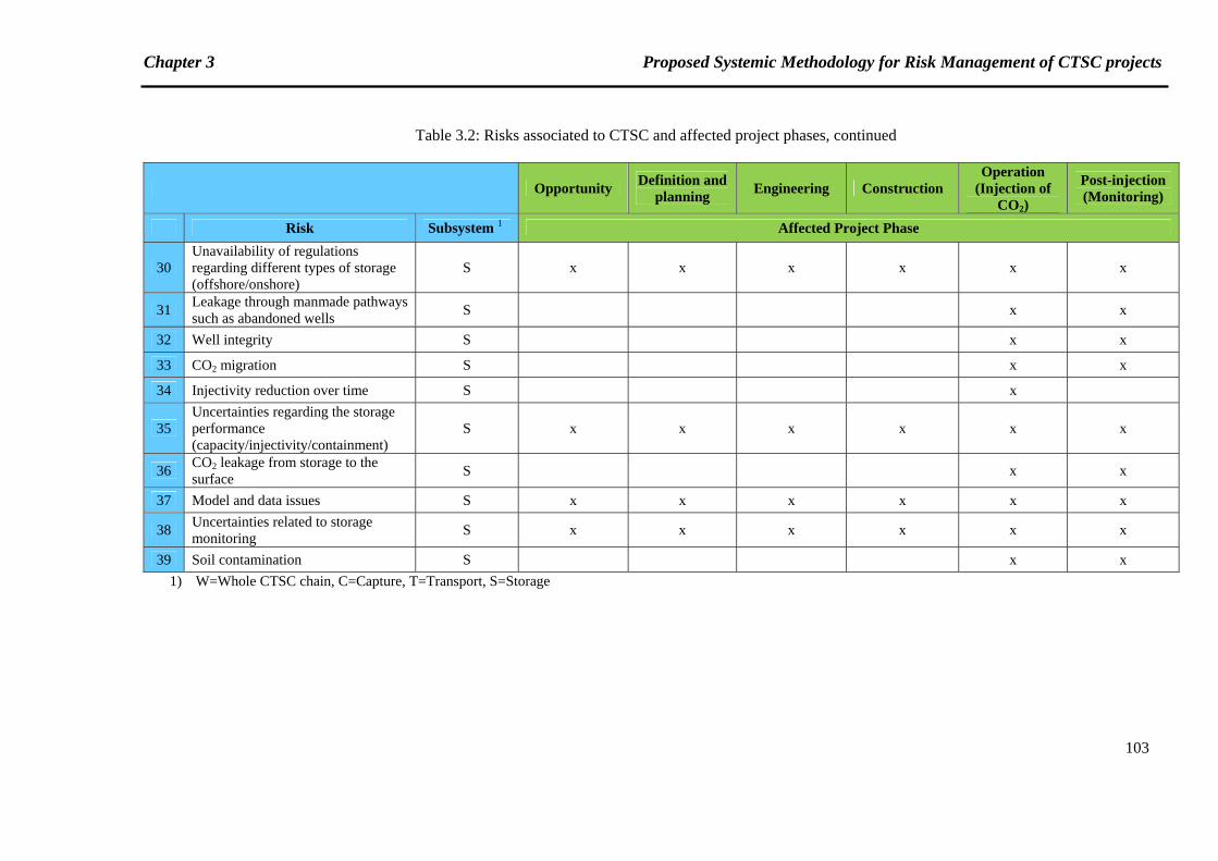
Chapter 3 Proposed Systemic Methodology for Risk Management of CTSC projects
103
Table 3.2: Risks associated to CTSC and affected project phases, continued
Opportunity Definition and
planning Engineering Construction
Operation (Injection of
CO2)
Post-injection (Monitoring)
Risk Subsystem 1 Affected Project Phase
30 Unavailability of regulations regarding different types of storage (offshore/onshore)
S x x x x x x
31 Leakage through manmade pathways such as abandoned wells
S x x
32 Well integrity S x x
33 CO2 migration S x x
34 Injectivity reduction over time S x
35 Uncertainties regarding the storage performance (capacity/injectivity/containment)
S x x x x x x
36 CO2 leakage from storage to the surface
S x x
37 Model and data issues S x x x x x x
38 Uncertainties related to storage monitoring
S x x x x x x
39 Soil contamination S x x
1) W=Whole CTSC chain, C=Capture, T=Transport, S=Storage
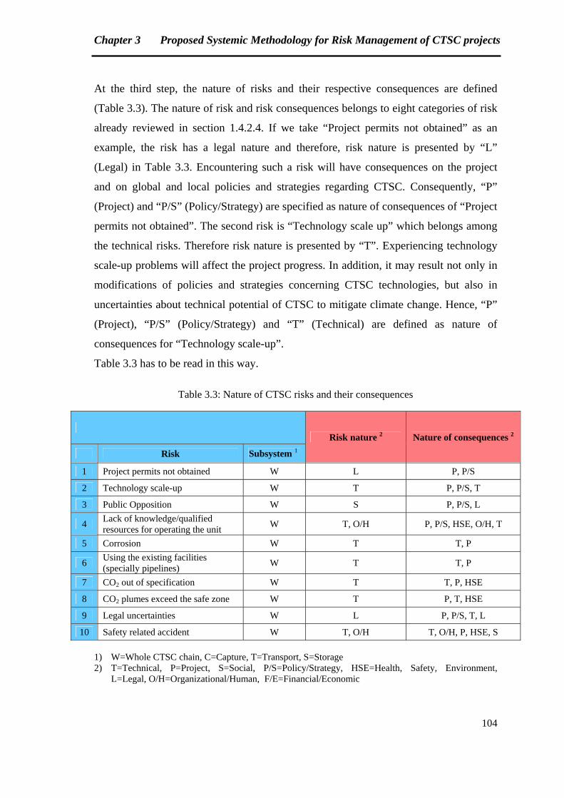
Chapter 3 Proposed Systemic Methodology for Risk Management of CTSC projects
104
At the third step, the nature of risks and their respective consequences are defined
(Table 3.3). The nature of risk and risk consequences belongs to eight categories of risk
already reviewed in section 1.4.2.4. If we take “Project permits not obtained” as an
example, the risk has a legal nature and therefore, risk nature is presented by “L”
(Legal) in Table 3.3. Encountering such a risk will have consequences on the project
and on global and local policies and strategies regarding CTSC. Consequently, “P”
(Project) and “P/S” (Policy/Strategy) are specified as nature of consequences of “Project
permits not obtained”. The second risk is “Technology scale up” which belongs among
the technical risks. Therefore risk nature is presented by “T”. Experiencing technology
scale-up problems will affect the project progress. In addition, it may result not only in
modifications of policies and strategies concerning CTSC technologies, but also in
uncertainties about technical potential of CTSC to mitigate climate change. Hence, “P”
(Project), “P/S” (Policy/Strategy) and “T” (Technical) are defined as nature of
consequences for “Technology scale-up”.
Table 3.3 has to be read in this way.
Table 3.3: Nature of CTSC risks and their consequences
Risk nature 2 Nature of consequences 2
Risk Subsystem 1
1 Project permits not obtained W L P, P/S
2 Technology scale-up W T P, P/S, T
3 Public Opposition W S P, P/S, L
4 Lack of knowledge/qualified resources for operating the unit
W T, O/H P, P/S, HSE, O/H, T
5 Corrosion W T T, P
6 Using the existing facilities (specially pipelines)
W T T, P
7 CO2 out of specification W T T, P, HSE
8 CO2 plumes exceed the safe zone W T P, T, HSE
9 Legal uncertainties W L P, P/S, T, L
10 Safety related accident W T, O/H T, O/H, P, HSE, S
1) W=Whole CTSC chain, C=Capture, T=Transport, S=Storage 2) T=Technical, P=Project, S=Social, P/S=Policy/Strategy, HSE=Health, Safety, Environment,
L=Legal, O/H=Organizational/Human, F/E=Financial/Economic
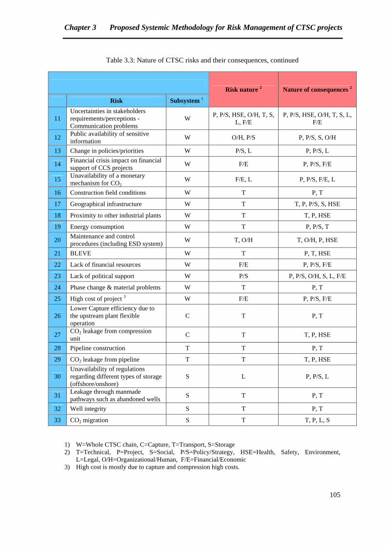
Chapter 3 Proposed Systemic Methodology for Risk Management of CTSC projects
105
Table 3.3: Nature of CTSC risks and their consequences, continued
Risk nature 2 Nature of consequences 2
Risk Subsystem 1
11 Uncertainties in stakeholders requirements/perceptions -Communication problems
W P, P/S, HSE, O/H, T, S,
L, F/E P, P/S, HSE, O/H, T, S, L,
F/E
12 Public availability of sensitive information
W O/H, P/S P, P/S, S, O/H
13 Change in policies/priorities W P/S, L P, P/S, L
14 Financial crisis impact on financial support of CCS projects
W F/E P, P/S, F/E
15 Unavailability of a monetary mechanism for CO2
W F/E, L P, P/S, F/E, L
16 Construction field conditions W T P, T
17 Geographical infrastructure W T T, P, P/S, S, HSE
18 Proximity to other industrial plants W T T, P, HSE
19 Energy consumption W T P, P/S, T
20 Maintenance and control procedures (including ESD system)
W T, O/H T, O/H, P, HSE
21 BLEVE W T P, T, HSE
22 Lack of financial resources W F/E P, P/S, F/E
23 Lack of political support W P/S P, P/S, O/H, S, L, F/E
24 Phase change & material problems W T P, T
25 High cost of project 3 W F/E P, P/S, F/E
26 Lower Capture efficiency due to the upstream plant flexible operation
C T P, T
27 CO2 leakage from compression unit
C T T, P, HSE
28 Pipeline construction T T P, T
29 CO2 leakage from pipeline T T T, P, HSE
30 Unavailability of regulations regarding different types of storage (offshore/onshore)
S L P, P/S, L
31 Leakage through manmade pathways such as abandoned wells
S T P, T
32 Well integrity S T P, T
33 CO2 migration S T T, P, L, S
1) W=Whole CTSC chain, C=Capture, T=Transport, S=Storage 2) T=Technical, P=Project, S=Social, P/S=Policy/Strategy, HSE=Health, Safety, Environment,
L=Legal, O/H=Organizational/Human, F/E=Financial/Economic 3) High cost is mostly due to capture and compression high costs.
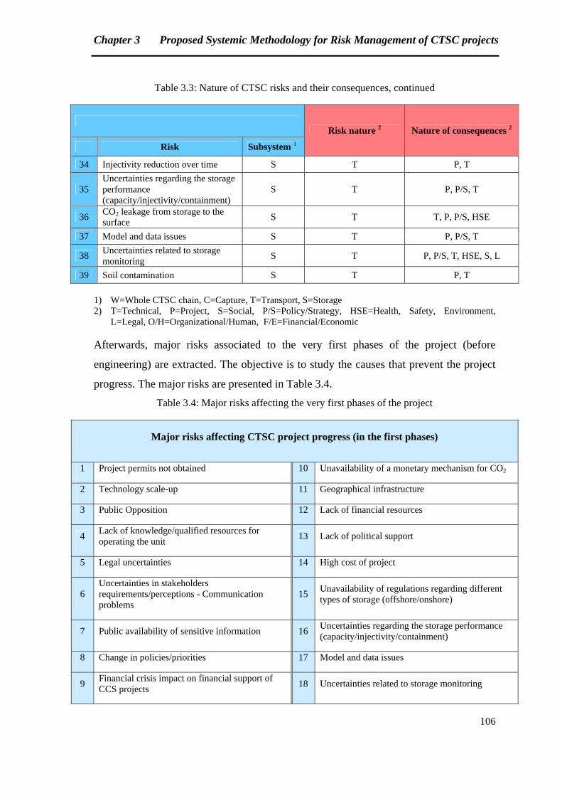
Chapter 3 Proposed Systemic Methodology for Risk Management of CTSC projects
106
Table 3.3: Nature of CTSC risks and their consequences, continued
Risk nature 2 Nature of consequences 2
Risk Subsystem 1
34 Injectivity reduction over time S T P, T
35 Uncertainties regarding the storage performance (capacity/injectivity/containment)
S T P, P/S, T
36 CO2 leakage from storage to the surface
S T T, P, P/S, HSE
37 Model and data issues S T P, P/S, T
38 Uncertainties related to storage monitoring
S T P, P/S, T, HSE, S, L
39 Soil contamination S T P, T
1) W=Whole CTSC chain, C=Capture, T=Transport, S=Storage 2) T=Technical, P=Project, S=Social, P/S=Policy/Strategy, HSE=Health, Safety, Environment,
L=Legal, O/H=Organizational/Human, F/E=Financial/Economic
Afterwards, major risks associated to the very first phases of the project (before
engineering) are extracted. The objective is to study the causes that prevent the project
progress. The major risks are presented in Table 3.4.
Table 3.4: Major risks affecting the very first phases of the project
Major risks affecting CTSC project progress (in the first phases)
1 Project permits not obtained 10 Unavailability of a monetary mechanism for CO2
2 Technology scale-up 11 Geographical infrastructure
3 Public Opposition 12 Lack of financial resources
4 Lack of knowledge/qualified resources for operating the unit
13 Lack of political support
5 Legal uncertainties 14 High cost of project
6 Uncertainties in stakeholders requirements/perceptions - Communication problems
15 Unavailability of regulations regarding different types of storage (offshore/onshore)
7 Public availability of sensitive information 16 Uncertainties regarding the storage performance (capacity/injectivity/containment)
8 Change in policies/priorities 17 Model and data issues
9 Financial crisis impact on financial support of CCS projects
18 Uncertainties related to storage monitoring
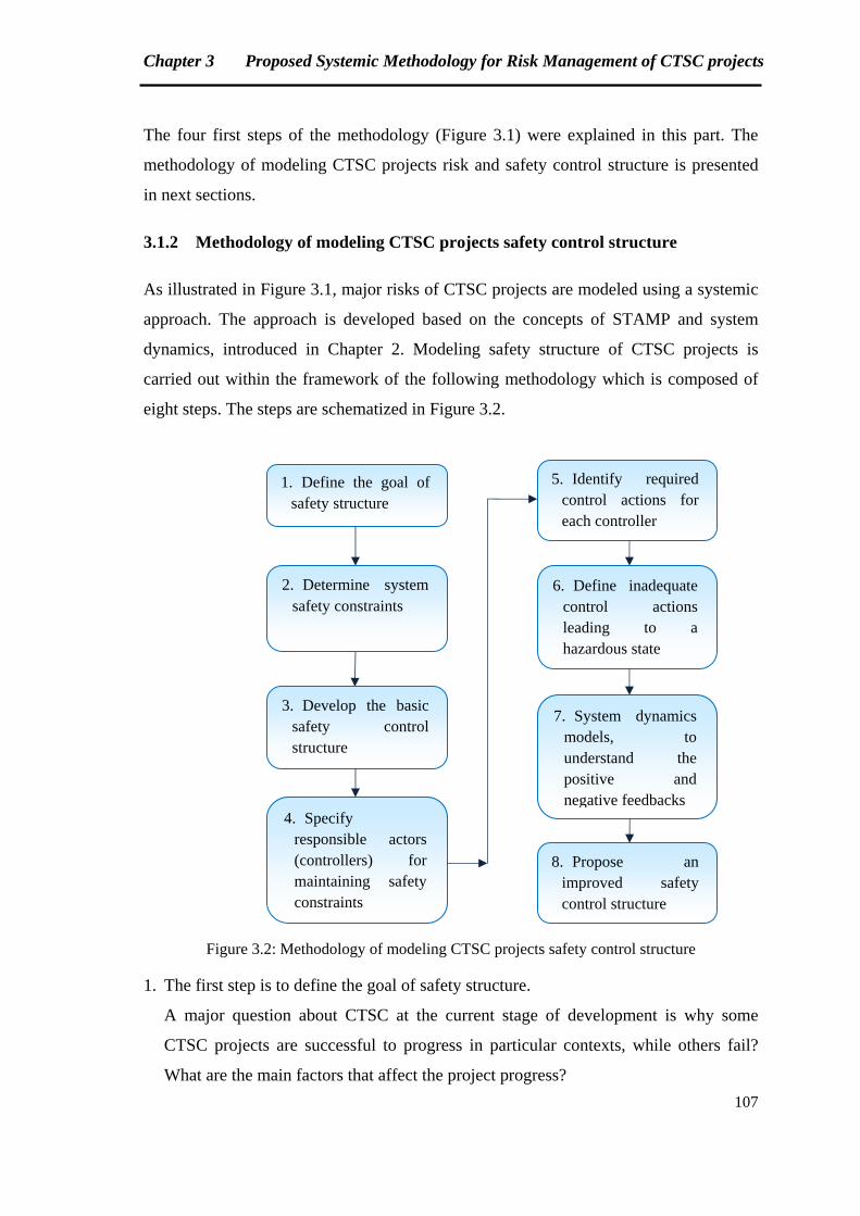
Chapter 3 Proposed Systemic Methodology for Risk Management of CTSC projects
107
The four first steps of the methodology (Figure 3.1) were explained in this part. The
methodology of modeling CTSC projects risk and safety control structure is presented
in next sections.
3.1.2 Methodology of modeling CTSC projects safety control structure
As illustrated in Figure 3.1, major risks of CTSC projects are modeled using a systemic
approach. The approach is developed based on the concepts of STAMP and system
dynamics, introduced in Chapter 2. Modeling safety structure of CTSC projects is
carried out within the framework of the following methodology which is composed of
eight steps. The steps are schematized in Figure 3.2.
Figure 3.2: Methodology of modeling CTSC projects safety control structure
1. The first step is to define the goal of safety structure.
A major question about CTSC at the current stage of development is why some
CTSC projects are successful to progress in particular contexts, while others fail?
What are the main factors that affect the project progress?
1. Define the goal of safety structure
2. Determine system safety constraints
3. Develop the basic safety control structure
4. Specify responsible actors (controllers) for maintaining safety constraints
5. Identify required control actions for each controller
6. Define inadequate control actions leading to a hazardous state
7. System dynamics models, to understand the positive and negative feedbacks
8. Propose an improved safety control structure
Chapter 3 Proposed Systemic Methodology for Risk Management of CTSC projects
108
Therefore, the goal of safety structure defined in this work is to prevent the delay or
cancelation of CTSC project.
This objective could be interpreted as definition and treatment of significant risks
that could prevent maintaining safety constraints.
As Leveson (2004b) affirms, there are four general ways to manage risks:
1. Eliminate the hazard from the system
2. Reduce the hazard likelihood
3. Assuring control measures when an undesired event is occurred
4. Minimize damage in case of control measures absence
2. In the second step, system safety constraints should be determined.
With the goal defined in the first step, the following constraints could be fixed for the
system:
1st system safety constraint: The project must not be delayed or cancelled.
2nd system safety constraint: Measures of control must be provided in case of delay
or cancellation.
In section 3.2, safety constraints will be detailed and analyzed for some major risks
(defined in Table 3.4). Other relevant steps will be also discussed for each risk.
3. The basic safety control structure is developed in the third stage. A general safety
control structure has been previously presented in Chapter 2, Figure 2.15.
The structure for CTSC is context specific, depending on several factors including
location, population density and historic issues [CCP, 2012]. However, the following
stakeholders are present in almost all cases:
- Project owner
- Politicians and Policy makers (National and Local)
- Regulators
- External experts
- Local population
- NGOs
- Media
Each of these stakeholders is a “controller” of the system, who is responsible for
maintaining specified safety constraints.

Chapter 3 Proposed Systemic Methodology for Risk Management of CTSC projects
109
The structures will be presented and discussed when we review the case studies in
chapter 4.
4. A question needs to be answered at this level. The question is who is responsible for
maintaining each safety constraint?
For the safety constraints introduced in the second step, project owner is directly
responsible. In other words, project owner is the endogenous controller, while other
actors are exogenous controllers, who could affect the system and decisions of the
project owner.
5. At this step, required control actions for each controller should be identified.
Required control actions are the tasks that should be performed in order to maintain
the safety constraints. These actions are risk specific and hence will be developed
later in section 3.2, when we present the constraints associated with each major risk.
6. Inadequate control actions that could lead to a hazardous state are defined in this
stage. Hazardous state is a state that violates the safety constraints [Leveson, 2004b,
p.24].
Leveson presents four general types of inadequate control:
1. A required control action is not provided.
2. An incorrect or unsafe control action is provided.
3. A potentially correct or adequate control action is provided too late (at the
wrong time).
4. A correct control action is stopped too soon.
7. System dynamics models, and especially causal graphs, are developed in this step.
The purpose is to study the positive and negative feedback loops which are involved
in the process of maintaining safety constraints. The models related to each major
risk will be discussed in section 3.2.
8. At the final step, an improved safety control structure is proposed based on the
analysis of inadequate control actions and causal graphs.
Chapter 3 Proposed Systemic Methodology for Risk Management of CTSC projects
110
3.2 General application of the methodology: Modeling major risks affecting
CTSC project progress
As discussed earlier, the goal of safety structure could be described as definition and
treatment of significant risks that could prevent maintaining safety constraints. The
safety constraints studied in this thesis are avoiding the projects delay or cancellation,
and providing control actions if required.
Major risks associated to the CTSC whole chain were reviewed in section 3.1 and
previously in Chapter 1. In this section, the specific safety constraints related to the
risks are reviewed, and a number of these risks are modeled using the approach
presented in section 3.1.2. Risks with different natures are selected in order to provide a
more comprehensive model of risks.
3.2.1 First example: risk of not obtaining project permits
The following safety constraint could be set for this example:
Safety constraint: Required permits shall be obtained for Capture, Transport and
Storage activities.
For understanding CTSC permitting procedures, a summary of significant points is
provided here based on the recent report of CO2 Capture Project on CTSC regulatory
issues [CCP, 2010].
Permitting requirements are not similar in different regions. There are two generic
approaches for regulating CO2 storage:
‐ Integrated exploration and storage licensing frameworks. This is the case of the EU.
‐ Legislative amendments associated with existing oil and gas exploration legislation.
This is the case in Australia, Canada and a part of the US.
In the EU, the CCS Directive provides the legal framework for permitting CCS
activities in the Member States. However, each country is interpreting the Directive to
provide a national framework.
The US and Canada are finalizing their CO2 storage legal frameworks. In the US,
regulations are provided at the Federal level. In Canada, Federal and Provincial
regulations for oil and gas are the basis of CTSC regulatory framework.
The EU CCS Directive determines two major permitting frameworks for CO2 storage:
Chapter 3 Proposed Systemic Methodology for Risk Management of CTSC projects
111
‐ The first one involves with the exploration phase, where further information is
needed to determine the suitability of the proposed site for CO2 injection. This stage
takes between 6 and 24 months to be realized.
‐ The second one is associated with the storage permit. A storage permit is a written
decision by a Member State Competent Authority (CA) authorizing the geological
storage of CO2 in a suitable storage site by the operator. Permitting is not required
for projects that are undertaken for research, development or testing of new products
and processes. The storage threshold for the determination of such projects is
100,000 tonnes of CO2 or less per year. Six to eight months are predicted for
obtaining storage permit in the EU.
A planning process of 2-11 years is also expected. In this stage, Environmental Impact
Assessment (EIA) is carried out.
The public and other third parties can influence the procedure by requesting additional
information and by challenging information that has been presented. Therefore, in
cases where there is public or third party opposition to the project, this stage of
permitting process is particularly vulnerable to the risk of delay.
To understand the permitting procedure for Capture and Transport, the concept of
“Carbon Capture Readiness” (CCR) should be reviewed. From 2009, all new
combustion plants applying for operating permit in the EU have to be “CCS Ready”.
“CCS Ready” has been defined by different organizations such as IEA Greenhouse Gas
R&D Program and GCCSI. Several points are still ambiguous in these definitions.
However, the aim is to prove that CTSC technology could be introduced to the plant in
the future.
In this part, we will not discuss the safety structure. Safety structures will be presented
and analyzed separately in chapter 4, for each case study.
Among the general stakeholders of CTSC project, project owner is responsible for
maintaining the safety constraint related to the risk of not obtaining project permits.
According to the permitting process explained earlier in this section, required control
actions for the controller (project owner) are as following:
‐ Providing CCS Ready requirements
‐ Requesting exploration permit if necessary
‐ Carrying out the Environmental Impact Assessment (EIA) to obtain storage permit
Chapter 3 Proposed Systemic Methodology for Risk Management of CTSC projects
112
‐ Communicating with the public and other stakeholders in order to avoid oppositions
which may lead to project delays
Therefore, several inadequate control actions could lead to a hazardous state, where
safety constraints are violated. If we take “Carrying out the Environmental Impact
Assessment (EIA) to obtain storage permit” as an example, the process presented by
ERM (Environmental Resources Management) on EIA application is as follows:
‐ Upon developer’s request, the competent authority sets out the EIA information to be
provided by the developer.
‐ The environmental authorities must be informed and consulted throughout the
process.
‐ The public must be informed and consulted. A common practice is a 30 day public
consultation after the EIA report is publicly published.
‐ If the EIA report is substantially changed as the result of the consultations, it has to
be put for another public consultation and so on, until there are no significant
changes needed.
‐ The competent authority decides on the acceptability of the report and the project,
taken into consideration the results of consultations.
‐ The public is informed of the decision afterwards and can challenge the decision
before the courts. [CCP, 2010, p.30]
A number of inadequate control actions could be named by focusing on the details of
the EIA application process. Hereafter, examples of such inadequate control actions are
provided:
1. Environmental Impact Assessment is not provided.
2. Environmental authorities or public are not informed and consulted throughout the
process.
3. Potential required changes of EIA report as the result of consultations are
implemented too late.
4. Communication with the stakeholders is stopped too soon. (Therefore, all
stakeholders feedbacks could not be taken into consideration in the EIA report).
Positive and negative feedbacks having an impact on the risk of not obtaining the
required permits are shown in the following figure:
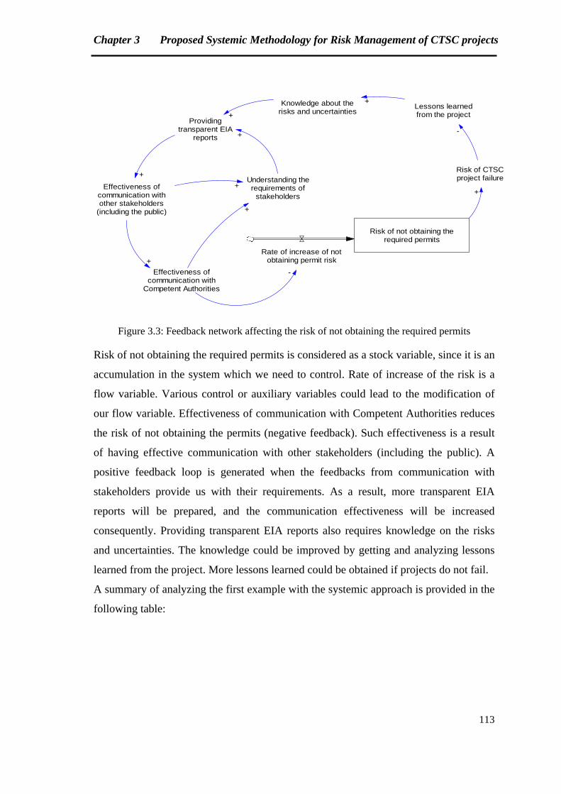
Chapter 3 Proposed Systemic Methodology for Risk Management of CTSC projects
113
Risk of not obtaining therequired permits
Rate of increase of notobtaining permit risk
Lessons learnedfrom the project
Knowledge about therisks and uncertainties
Effectiveness ofcommunication withother stakeholders
(including the public)
Effectiveness ofcommunication with
Competent Authorities
+
+
-
Risk of CTSCproject failure
+
-Providing
transparent EIAreports
Understanding therequirements of
stakeholders
+
+
+
+
+
Figure 3.3: Feedback network affecting the risk of not obtaining the required permits
Risk of not obtaining the required permits is considered as a stock variable, since it is an
accumulation in the system which we need to control. Rate of increase of the risk is a
flow variable. Various control or auxiliary variables could lead to the modification of
our flow variable. Effectiveness of communication with Competent Authorities reduces
the risk of not obtaining the permits (negative feedback). Such effectiveness is a result
of having effective communication with other stakeholders (including the public). A
positive feedback loop is generated when the feedbacks from communication with
stakeholders provide us with their requirements. As a result, more transparent EIA
reports will be prepared, and the communication effectiveness will be increased
consequently. Providing transparent EIA reports also requires knowledge on the risks
and uncertainties. The knowledge could be improved by getting and analyzing lessons
learned from the project. More lessons learned could be obtained if projects do not fail.
A summary of analyzing the first example with the systemic approach is provided in the
following table:
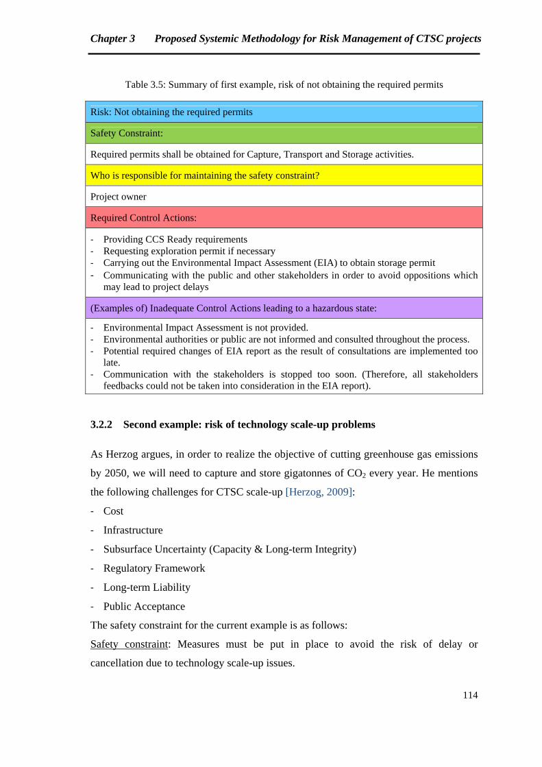
Chapter 3 Proposed Systemic Methodology for Risk Management of CTSC projects
114
Table 3.5: Summary of first example, risk of not obtaining the required permits
Risk: Not obtaining the required permits
Safety Constraint:
Required permits shall be obtained for Capture, Transport and Storage activities.
Who is responsible for maintaining the safety constraint?
Project owner
Required Control Actions:
‐ Providing CCS Ready requirements ‐ Requesting exploration permit if necessary ‐ Carrying out the Environmental Impact Assessment (EIA) to obtain storage permit ‐ Communicating with the public and other stakeholders in order to avoid oppositions which
may lead to project delays
(Examples of) Inadequate Control Actions leading to a hazardous state:
‐ Environmental Impact Assessment is not provided. ‐ Environmental authorities or public are not informed and consulted throughout the process. ‐ Potential required changes of EIA report as the result of consultations are implemented too
late. ‐ Communication with the stakeholders is stopped too soon. (Therefore, all stakeholders
feedbacks could not be taken into consideration in the EIA report).
3.2.2 Second example: risk of technology scale-up problems
As Herzog argues, in order to realize the objective of cutting greenhouse gas emissions
by 2050, we will need to capture and store gigatonnes of CO2 every year. He mentions
the following challenges for CTSC scale-up [Herzog, 2009]:
‐ Cost
‐ Infrastructure
‐ Subsurface Uncertainty (Capacity & Long-term Integrity)
‐ Regulatory Framework
‐ Long-term Liability
‐ Public Acceptance
The safety constraint for the current example is as follows:
Safety constraint: Measures must be put in place to avoid the risk of delay or
cancellation due to technology scale-up issues.
Chapter 3 Proposed Systemic Methodology for Risk Management of CTSC projects
115
According to Herzog’s point of view, CTSC technology scale-up is a complex issue that
depends on various factors. Hence, several stakeholders are involved as the controllers
of such a complex subject.
Project owner and Competent Authorities could be considered as endogenous
controllers, while Regulators, Local population and others are the exogenous
controllers, which have impacts on the decisions of endogenous actors. In this report,
we focus on the endogenous ones.
Required control actions for each controller are as coming next:
For project owner:
‐ Providing the required elements to minimize the uncertainties associated to
subsurface and storage long term liability
‐ Ensuring the public acceptance of the project development
‐ Providing the necessary infrastructure
‐ Providing technologies with optimized acceptable costs
And for Competent Authorities:
‐ Providing regulatory frameworks for CTSC activities
Once again, a number of inadequate control actions could be analyzed for each
controller. Examples of inadequate control actions of project owner on the subject of
“providing technologies with optimized acceptable costs” are as following:
1. Acceptable costs are not proposed for CTSC technologies.
2. Best available costs are proposed by the developers, but not accepted by the
authorities because of uncertainties/ambiguities of acceptable costs range.
3. Economically acceptable options are made available too late.
4. Research and Developments are not continued to find more economic technological
possibilities (as soon as an option is accepted by the authorities) (There is a risk of
changing range of acceptable costs over time).
The feedbacks involved in controlling the rate of increase of technology scale-up
problems are illustrated in the following causal graph:
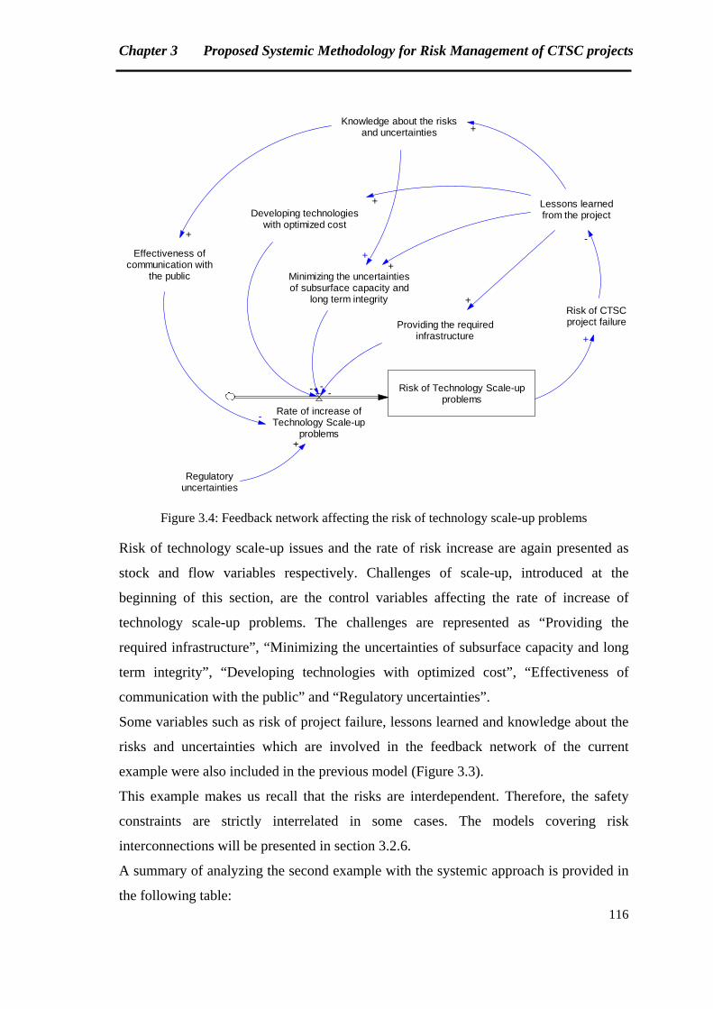
Chapter 3 Proposed Systemic Methodology for Risk Management of CTSC projects
116
Risk of Technology Scale-upproblems
Rate of increase ofTechnology Scale-up
problems
Lessons learnedfrom the project
Knowledge about the risksand uncertainties
Effectiveness ofcommunication with
the public
Regulatoryuncertainties
+
+
Risk of CTSCproject failure
-
Providing the requiredinfrastructure
Developing technologieswith optimized cost
Minimizing the uncertaintiesof subsurface capacity and
long term integrity
+
+
+
+
---
+
-
+
Figure 3.4: Feedback network affecting the risk of technology scale-up problems
Risk of technology scale-up issues and the rate of risk increase are again presented as
stock and flow variables respectively. Challenges of scale-up, introduced at the
beginning of this section, are the control variables affecting the rate of increase of
technology scale-up problems. The challenges are represented as “Providing the
required infrastructure”, “Minimizing the uncertainties of subsurface capacity and long
term integrity”, “Developing technologies with optimized cost”, “Effectiveness of
communication with the public” and “Regulatory uncertainties”.
Some variables such as risk of project failure, lessons learned and knowledge about the
risks and uncertainties which are involved in the feedback network of the current
example were also included in the previous model (Figure 3.3).
This example makes us recall that the risks are interdependent. Therefore, the safety
constraints are strictly interrelated in some cases. The models covering risk
interconnections will be presented in section 3.2.6.
A summary of analyzing the second example with the systemic approach is provided in
the following table:
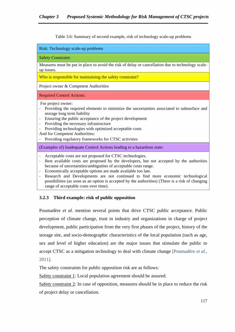
Chapter 3 Proposed Systemic Methodology for Risk Management of CTSC projects
117
Table 3.6: Summary of second example, risk of technology scale-up problems
Risk: Technology scale-up problems
Safety Constraint:
Measures must be put in place to avoid the risk of delay or cancellation due to technology scale-up issues.
Who is responsible for maintaining the safety constraint?
Project owner & Competent Authorities
Required Control Actions:
For project owner: ‐ Providing the required elements to minimize the uncertainties associated to subsurface and
storage long term liability ‐ Ensuring the public acceptance of the project development ‐ Providing the necessary infrastructure ‐ Providing technologies with optimized acceptable costs And for Competent Authorities: ‐ Providing regulatory frameworks for CTSC activities
(Examples of) Inadequate Control Actions leading to a hazardous state:
‐ Acceptable costs are not proposed for CTSC technologies. ‐ Best available costs are proposed by the developers, but not accepted by the authorities
because of uncertainties/ambiguities of acceptable costs range. ‐ Economically acceptable options are made available too late. ‐ Research and Developments are not continued to find more economic technological
possibilities (as soon as an option is accepted by the authorities) (There is a risk of changing range of acceptable costs over time).
3.2.3 Third example: risk of public opposition
Poumadère et al. mention several points that drive CTSC public acceptance. Public
perception of climate change, trust in industry and organizations in charge of project
development, public participation from the very first phases of the project, history of the
storage site, and socio-demographic characteristics of the local population (such as age,
sex and level of higher education) are the major issues that stimulate the public to
accept CTSC as a mitigation technology to deal with climate change [Poumadère et al.,
2011].
The safety constraints for public opposition risk are as follows:
Safety constraint 1: Local population agreement should be assured.
Safety constraint 2: In case of opposition, measures should be in place to reduce the risk
of project delay or cancellation.
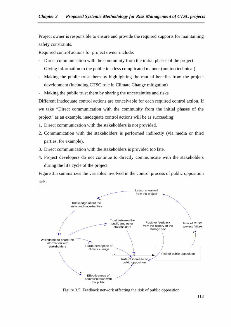
Chapter 3 Proposed Systemic Methodology for Risk Management of CTSC projects
118
Project owner is responsible to ensure and provide the required supports for maintaining
safety constraints.
Required control actions for project owner include:
‐ Direct communication with the community from the initial phases of the project
‐ Giving information to the public in a less complicated manner (not too technical)
‐ Making the public trust them by highlighting the mutual benefits from the project
development (including CTSC role in Climate Change mitigation)
‐ Making the public trust them by sharing the uncertainties and risks
Different inadequate control actions are conceivable for each required control action. If
we take “Direct communication with the community from the initial phases of the
project” as an example, inadequate control actions will be as succeeding:
1. Direct communication with the stakeholders is not provided.
2. Communication with the stakeholders is performed indirectly (via media or third
parties, for example).
3. Direct communication with the stakeholders is provided too late.
4. Project developers do not continue to directly communicate with the stakeholders
during the life cycle of the project.
Figure 3.5 summarizes the variables involved in the control process of public opposition
risk.
Risk of public opposition
Rate of increase ofpublic opposition
Lessons learnedfrom the project
Knowledge about therisks and uncertainties
Willingness to share theinformation with
stakeholders
Effectiveness ofcommunication with
the public
+
+
+
-
Risk of CTSCproject failure
+
-
Positive feedbackfrom the history of the
storage site
Trust between thepublic and other
stakeholders
-
-
Public perception ofclimate change
+
+
-
Figure 3.5: Feedback network affecting the risk of public opposition
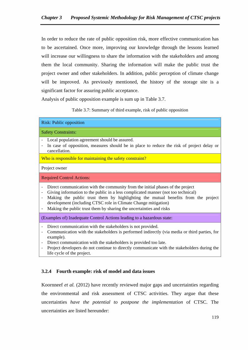
Chapter 3 Proposed Systemic Methodology for Risk Management of CTSC projects
119
In order to reduce the rate of public opposition risk, more effective communication has
to be ascertained. Once more, improving our knowledge through the lessons learned
will increase our willingness to share the information with the stakeholders and among
them the local community. Sharing the information will make the public trust the
project owner and other stakeholders. In addition, public perception of climate change
will be improved. As previously mentioned, the history of the storage site is a
significant factor for assuring public acceptance.
Analysis of public opposition example is sum up in Table 3.7.
Table 3.7: Summary of third example, risk of public opposition
Risk: Public opposition
Safety Constraints:
‐ Local population agreement should be assured. ‐ In case of opposition, measures should be in place to reduce the risk of project delay or
cancellation.
Who is responsible for maintaining the safety constraint?
Project owner
Required Control Actions:
‐ Direct communication with the community from the initial phases of the project ‐ Giving information to the public in a less complicated manner (not too technical) ‐ Making the public trust them by highlighting the mutual benefits from the project
development (including CTSC role in Climate Change mitigation) ‐ Making the public trust them by sharing the uncertainties and risks
(Examples of) Inadequate Control Actions leading to a hazardous state:
‐ Direct communication with the stakeholders is not provided. ‐ Communication with the stakeholders is performed indirectly (via media or third parties, for
example). ‐ Direct communication with the stakeholders is provided too late. ‐ Project developers do not continue to directly communicate with the stakeholders during the
life cycle of the project.
3.2.4 Fourth example: risk of model and data issues
Koornneef et al. (2012) have recently reviewed major gaps and uncertainties regarding
the environmental and risk assessment of CTSC activities. They argue that these
uncertainties have the potential to postpone the implementation of CTSC. The
uncertainties are listed hereunder:
Chapter 3 Proposed Systemic Methodology for Risk Management of CTSC projects
120
Capture:
‐ Uncertainties concerning quantification of atmospheric emissions when a CO2
capture process is integrated in a power plant
‐ Uncertainties about flows and composition of wastes and byproducts of power plants
with CO2 capture
Transport:
‐ Uncertainties about the rate and characteristics of CO2 pipeline leakage
‐ Uncertainties related to corrosion rates of pipelines when impurities such as H2O,
SOx, NOx, N2, O2, H2S, CO and H2 are present.
‐ Uncertainties about the effects of impurities in dispersion models
Storage:
‐ Uncertainties regarding characteristics (amount and speed) of fluxes between
subsurface compartments and possible leakage pathways
‐ Uncertainties concerning sealing capacity (containment), injectivity and storage
capacity
‐ Uncertainties about monitoring of deep subsurface
‐ Additional uncertainties due to the post-closure phase, which is specific to CO2 long
term storage
Most of the uncertainties are linked to modeling issues. Modeling is a dynamic process
which begins at the initial phase of the project. Models are continually updated and
validated based on the lessons learned and the information acquired from the field.
Koornneef et al. (2012) mention that modeling CO2 behavior in reservoirs has been
already experienced in EOR projects. However, geochemical, geophysical and
hydrodynamic interactions of CO2 with the reservoir have not been detailed. Therefore,
the models are not calibrated yet for long term CO2 storage.
Dynamic evolution of uncertainties during the life cycle of CTSC project is illustrated
in the following figure:
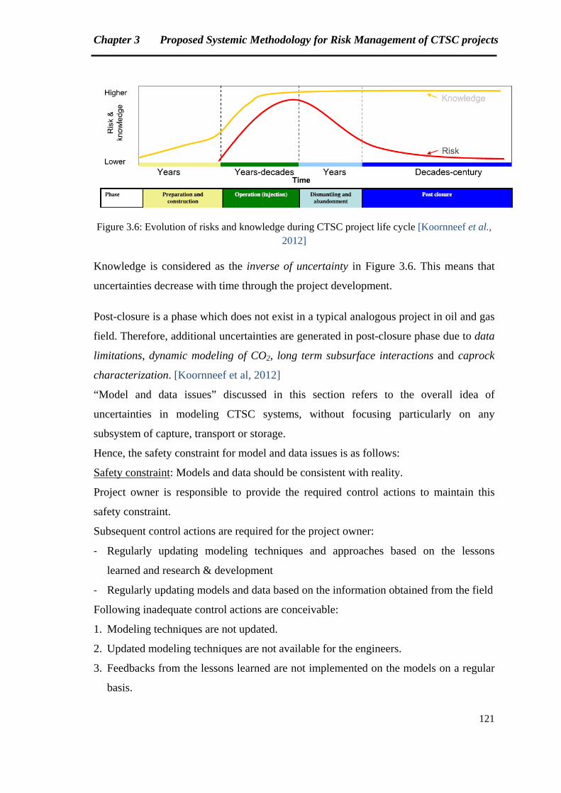
Chapter 3 Proposed Systemic Methodology for Risk Management of CTSC projects
121
Figure 3.6: Evolution of risks and knowledge during CTSC project life cycle [Koornneef et al.,
2012]
Knowledge is considered as the inverse of uncertainty in Figure 3.6. This means that
uncertainties decrease with time through the project development.
Post-closure is a phase which does not exist in a typical analogous project in oil and gas
field. Therefore, additional uncertainties are generated in post-closure phase due to data
limitations, dynamic modeling of CO2, long term subsurface interactions and caprock
characterization. [Koornneef et al, 2012]
“Model and data issues” discussed in this section refers to the overall idea of
uncertainties in modeling CTSC systems, without focusing particularly on any
subsystem of capture, transport or storage.
Hence, the safety constraint for model and data issues is as follows:
Safety constraint: Models and data should be consistent with reality.
Project owner is responsible to provide the required control actions to maintain this
safety constraint.
Subsequent control actions are required for the project owner:
‐ Regularly updating modeling techniques and approaches based on the lessons
learned and research & development
‐ Regularly updating models and data based on the information obtained from the field
Following inadequate control actions are conceivable:
1. Modeling techniques are not updated.
2. Updated modeling techniques are not available for the engineers.
3. Feedbacks from the lessons learned are not implemented on the models on a regular
basis.
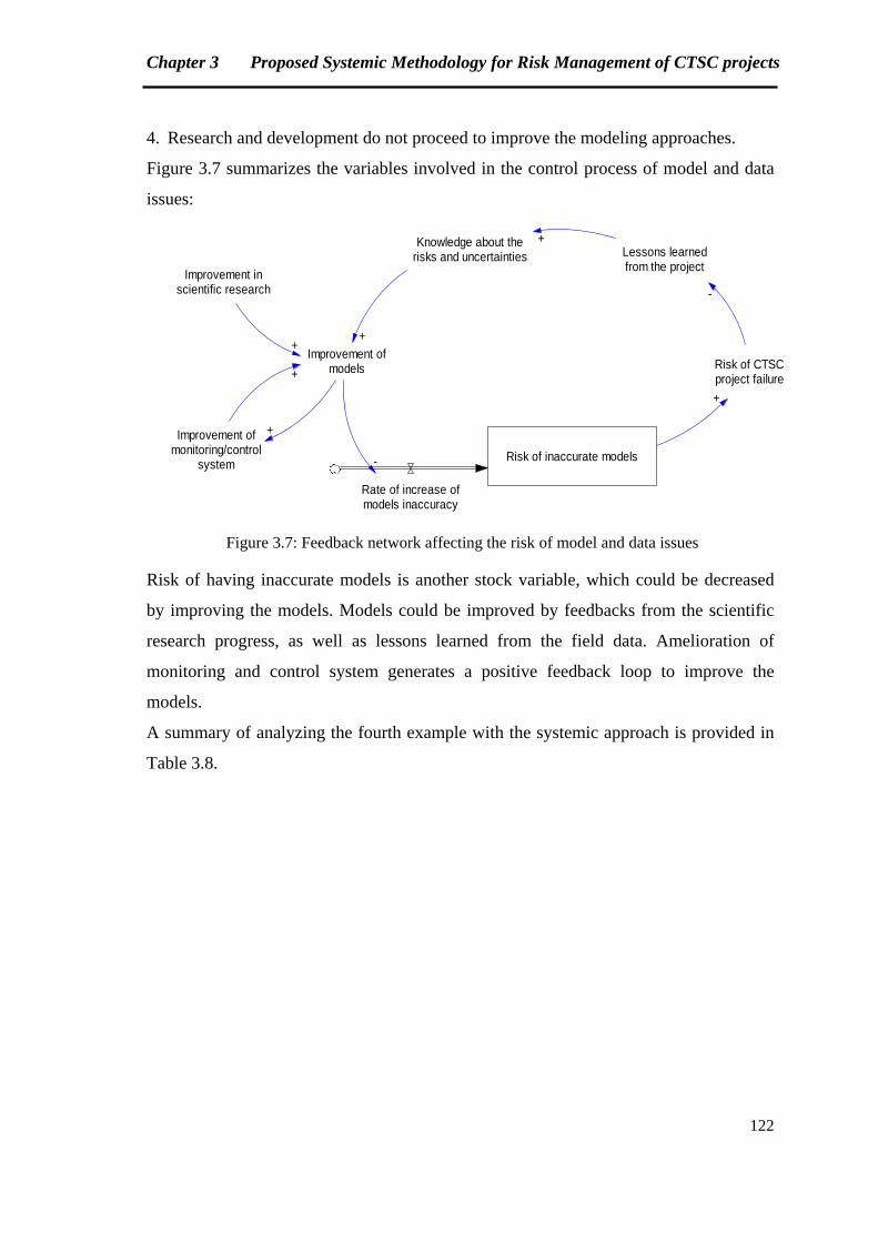
Chapter 3 Proposed Systemic Methodology for Risk Management of CTSC projects
122
4. Research and development do not proceed to improve the modeling approaches.
Figure 3.7 summarizes the variables involved in the control process of model and data
issues:
Risk of inaccurate models
Rate of increase ofmodels inaccuracy
Knowledge about therisks and uncertainties
Risk of CTSCproject failure
+
Improvement ofmodels
Improvement inscientific research
Improvement ofmonitoring/control
system
++
-
Lessons learnedfrom the project
-
+
+
+
Figure 3.7: Feedback network affecting the risk of model and data issues
Risk of having inaccurate models is another stock variable, which could be decreased
by improving the models. Models could be improved by feedbacks from the scientific
research progress, as well as lessons learned from the field data. Amelioration of
monitoring and control system generates a positive feedback loop to improve the
models.
A summary of analyzing the fourth example with the systemic approach is provided in
Table 3.8.
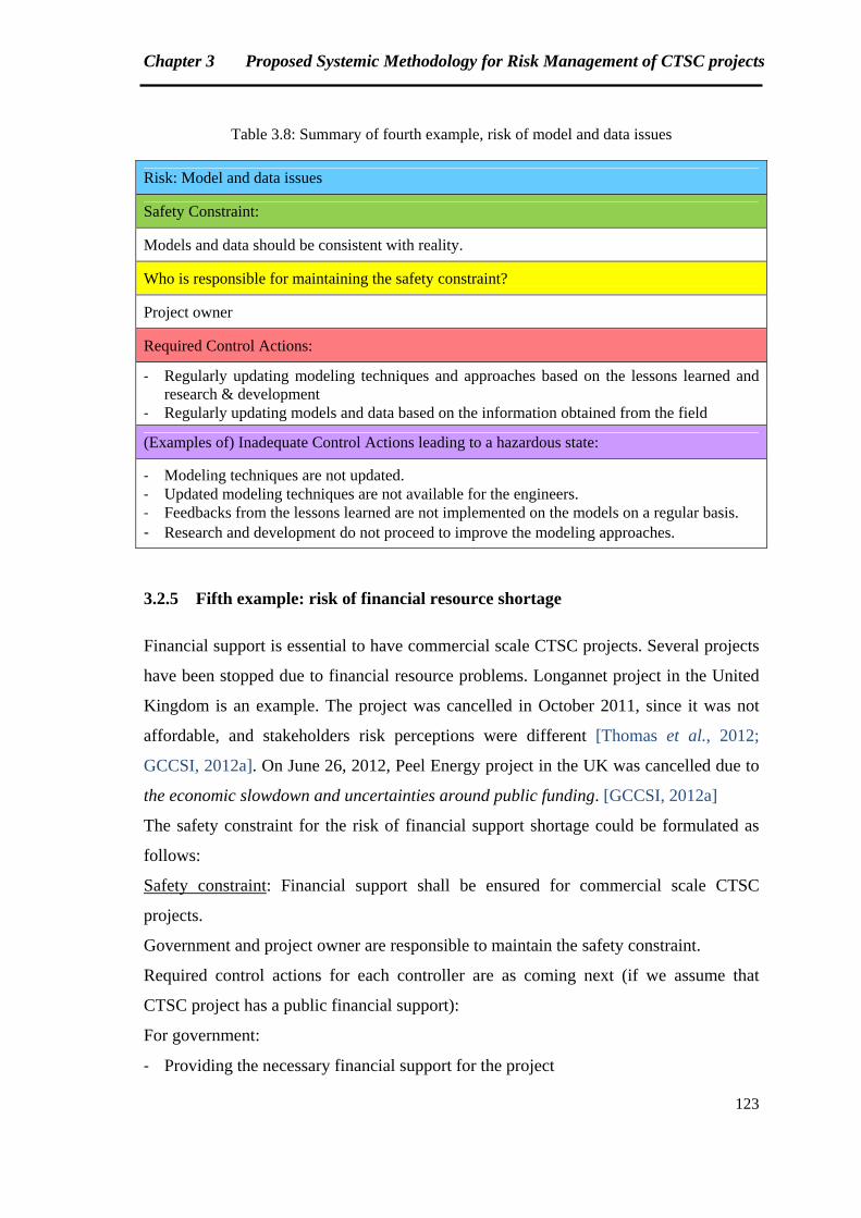
Chapter 3 Proposed Systemic Methodology for Risk Management of CTSC projects
123
Table 3.8: Summary of fourth example, risk of model and data issues
Risk: Model and data issues
Safety Constraint:
Models and data should be consistent with reality.
Who is responsible for maintaining the safety constraint?
Project owner
Required Control Actions:
‐ Regularly updating modeling techniques and approaches based on the lessons learned and research & development
‐ Regularly updating models and data based on the information obtained from the field
(Examples of) Inadequate Control Actions leading to a hazardous state:
‐ Modeling techniques are not updated. ‐ Updated modeling techniques are not available for the engineers. ‐ Feedbacks from the lessons learned are not implemented on the models on a regular basis. ‐ Research and development do not proceed to improve the modeling approaches.
3.2.5 Fifth example: risk of financial resource shortage
Financial support is essential to have commercial scale CTSC projects. Several projects
have been stopped due to financial resource problems. Longannet project in the United
Kingdom is an example. The project was cancelled in October 2011, since it was not
affordable, and stakeholders risk perceptions were different [Thomas et al., 2012;
GCCSI, 2012a]. On June 26, 2012, Peel Energy project in the UK was cancelled due to
the economic slowdown and uncertainties around public funding. [GCCSI, 2012a]
The safety constraint for the risk of financial support shortage could be formulated as
follows:
Safety constraint: Financial support shall be ensured for commercial scale CTSC
projects.
Government and project owner are responsible to maintain the safety constraint.
Required control actions for each controller are as coming next (if we assume that
CTSC project has a public financial support):
For government:
‐ Providing the necessary financial support for the project
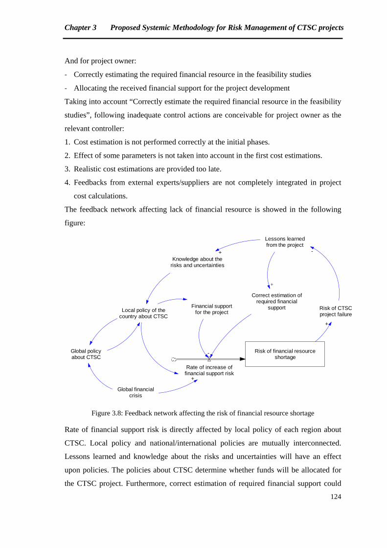
Chapter 3 Proposed Systemic Methodology for Risk Management of CTSC projects
124
And for project owner:
‐ Correctly estimating the required financial resource in the feasibility studies
‐ Allocating the received financial support for the project development
Taking into account “Correctly estimate the required financial resource in the feasibility
studies”, following inadequate control actions are conceivable for project owner as the
relevant controller:
1. Cost estimation is not performed correctly at the initial phases.
2. Effect of some parameters is not taken into account in the first cost estimations.
3. Realistic cost estimations are provided too late.
4. Feedbacks from external experts/suppliers are not completely integrated in project
cost calculations.
The feedback network affecting lack of financial resource is showed in the following
figure:
Risk of financial resourceshortage
Rate of increase offinancial support risk
Knowledge about therisks and uncertainties
Risk of CTSCproject failure
+
Local policy of thecountry about CTSC
Lessons learnedfrom the project
Global policyabout CTSC
-+
Global financialcrisis
+
Financial supportfor the project
Correct estimation ofrequired financial
support
+
-
Figure 3.8: Feedback network affecting the risk of financial resource shortage
Rate of financial support risk is directly affected by local policy of each region about
CTSC. Local policy and national/international policies are mutually interconnected.
Lessons learned and knowledge about the risks and uncertainties will have an effect
upon policies. The policies about CTSC determine whether funds will be allocated for
the CTSC project. Furthermore, correct estimation of required financial support could
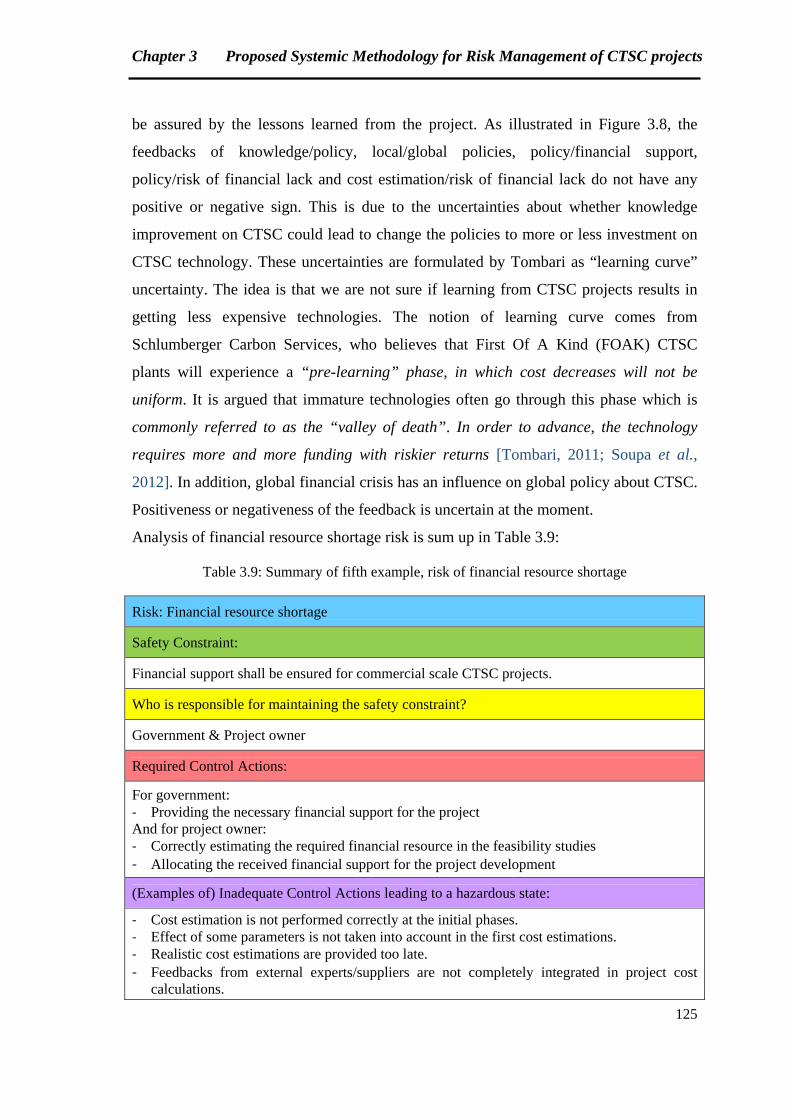
Chapter 3 Proposed Systemic Methodology for Risk Management of CTSC projects
125
be assured by the lessons learned from the project. As illustrated in Figure 3.8, the
feedbacks of knowledge/policy, local/global policies, policy/financial support,
policy/risk of financial lack and cost estimation/risk of financial lack do not have any
positive or negative sign. This is due to the uncertainties about whether knowledge
improvement on CTSC could lead to change the policies to more or less investment on
CTSC technology. These uncertainties are formulated by Tombari as “learning curve”
uncertainty. The idea is that we are not sure if learning from CTSC projects results in
getting less expensive technologies. The notion of learning curve comes from
Schlumberger Carbon Services, who believes that First Of A Kind (FOAK) CTSC
plants will experience a “pre-learning” phase, in which cost decreases will not be
uniform. It is argued that immature technologies often go through this phase which is
commonly referred to as the “valley of death”. In order to advance, the technology
requires more and more funding with riskier returns [Tombari, 2011; Soupa et al.,
2012]. In addition, global financial crisis has an influence on global policy about CTSC.
Positiveness or negativeness of the feedback is uncertain at the moment.
Analysis of financial resource shortage risk is sum up in Table 3.9:
Table 3.9: Summary of fifth example, risk of financial resource shortage
Risk: Financial resource shortage
Safety Constraint:
Financial support shall be ensured for commercial scale CTSC projects.
Who is responsible for maintaining the safety constraint?
Government & Project owner
Required Control Actions:
For government: ‐ Providing the necessary financial support for the project And for project owner: ‐ Correctly estimating the required financial resource in the feasibility studies ‐ Allocating the received financial support for the project development
(Examples of) Inadequate Control Actions leading to a hazardous state:
‐ Cost estimation is not performed correctly at the initial phases. ‐ Effect of some parameters is not taken into account in the first cost estimations. ‐ Realistic cost estimations are provided too late. ‐ Feedbacks from external experts/suppliers are not completely integrated in project cost
calculations.
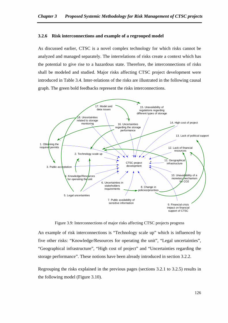
Chapter 3 Proposed Systemic Methodology for Risk Management of CTSC projects
126
3.2.6 Risk interconnections and example of a regrouped model
As discussed earlier, CTSC is a novel complex technology for which risks cannot be
analyzed and managed separately. The interrelations of risks create a context which has
the potential to give rise to a hazardous state. Therefore, the interconnections of risks
shall be modeled and studied. Major risks affecting CTSC project development were
introduced in Table 3.4. Inter-relations of the risks are illustrated in the following causal
graph. The green bold feedbacks represent the risks interconnections.
CTSC projectdevelopment
1. Obtaining therequired permits
+
2. Technology scale up
+
3. Public acceptation +
4. Knowledge/Resourcesfor operating the unit
+
5. Legal uncertainties
6. Uncertainties instakeholdersrequirements
7. Public availability ofsensitive information
8. Change inpolicies/priorities
9. Financial crisisimpact on financialsupport of CTSC
10. Unavailability of amonetary mechanism
for CO2
11. Geographicalinfrastructure
12. Lack of financialresources
13. Lack of political support
14. High cost of project
15. Unavailability ofregulations regarding
different types of storage
16. Uncertaintiesregarding the storage
performance
17. Model anddata issues
18. Uncertaintiesrelated to storage
monitoring
--
--
+
------- +
+
-
- +
+
-
--+
Figure 3.9: Interconnections of major risks affecting CTSC projects progress
An example of risk interconnections is “Technology scale up” which is influenced by
five other risks: “Knowledge/Resources for operating the unit”, “Legal uncertainties”,
“Geographical infrastructure”, “High cost of project” and “Uncertainties regarding the
storage performance”. These notions have been already introduced in section 3.2.2.
Regrouping the risks explained in the previous pages (sections 3.2.1 to 3.2.5) results in
the following model (Figure 3.10).
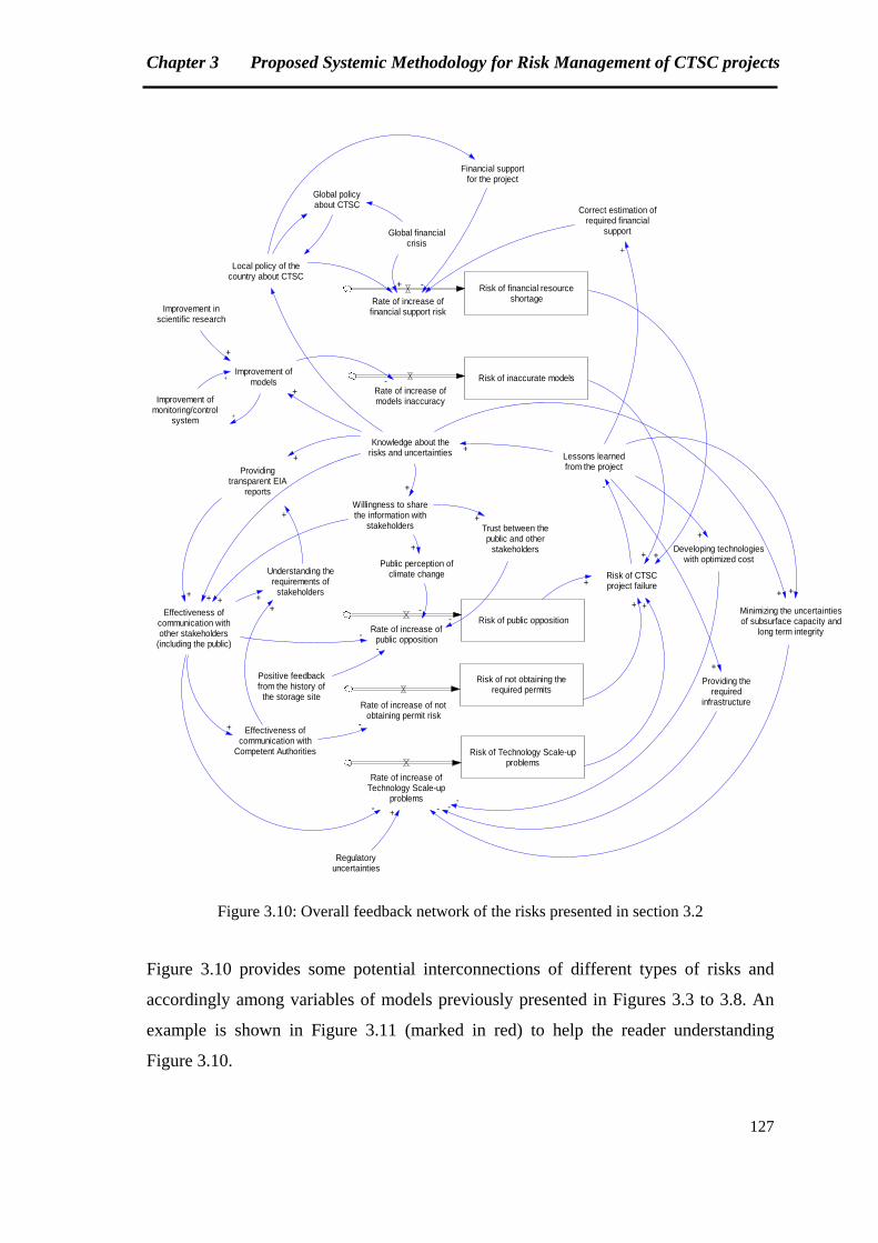
Chapter 3 Proposed Systemic Methodology for Risk Management of CTSC projects
127
Risk of not obtaining therequired permits
Rate of increase of notobtaining permit risk
Lessons learnedfrom the project
Knowledge about therisks and uncertainties
Effectiveness ofcommunication withother stakeholders
(including the public)
Effectiveness ofcommunication with
Competent Authorities
+
+ -
Risk of CTSCproject failure
+
-
Providingtransparent EIA
reports
Understanding therequirements of
stakeholders
+
+ ++
+
Risk of Technology Scale-upproblems
+
Rate of increase ofTechnology Scale-up
problems-
Regulatoryuncertainties
+
Developing technologieswith optimized cost
+
-
Minimizing the uncertaintiesof subsurface capacity and
long term integrity
++
-
Providing therequired
infrastructure
+
-
Risk of public oppositionRate of increase of
public opposition
+
Willingness to sharethe information with
stakeholders
+
+
-
Public perception ofclimate change
+
-
Trust between thepublic and other
stakeholders
+
-
Positive feedbackfrom the history of
the storage site
-
Risk of inaccurate modelsRate of increase ofmodels inaccuracy
+
Improvement ofmodels
+-
Improvement inscientific research
+
Improvement ofmonitoring/control
system
+
+
Risk of financial resourceshortageRate of increase of
financial support risk
+
Local policy of thecountry about CTSC
Global policyabout CTSC
Global financialcrisis
+
+
Correct estimation ofrequired financial
support
Financial supportfor the project
+
-
Figure 3.10: Overall feedback network of the risks presented in section 3.2
Figure 3.10 provides some potential interconnections of different types of risks and
accordingly among variables of models previously presented in Figures 3.3 to 3.8. An
example is shown in Figure 3.11 (marked in red) to help the reader understanding
Figure 3.10.
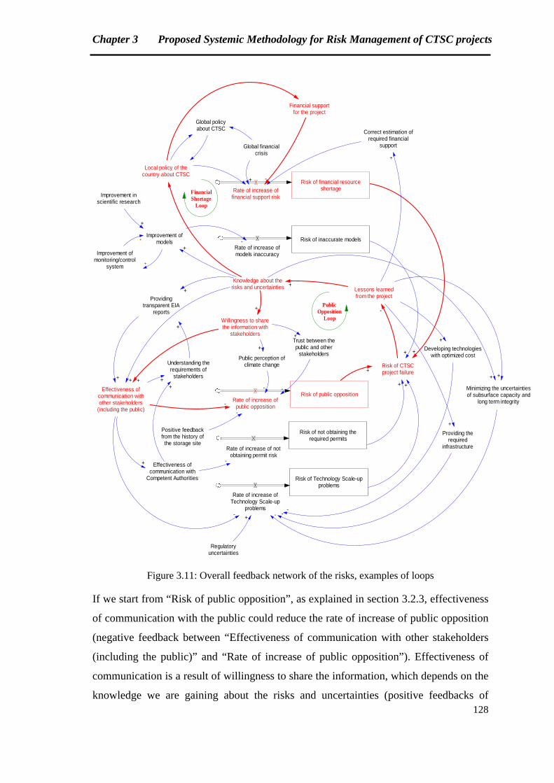
Chapter 3 Proposed Systemic Methodology for Risk Management of CTSC projects
128
Risk of not obtaining therequired permits
Rate of increase of notobtaining permit risk
Lessons learnedfrom the project
Knowledge about therisks and uncertainties
Effectiveness ofcommunication withother stakeholders
(including the public)
Effectiveness ofcommunication with
Competent Authorities
+
+ -
Risk of CTSCproject failure
+
-
Providingtransparent EIA
reports
Understanding therequirements of
stakeholders
+
+ ++
+
Risk of Technology Scale-upproblems
+
Rate of increase ofTechnology Scale-up
problems-
Regulatoryuncertainties
+
Developing technologieswith optimized cost
+
-
Minimizing the uncertaintiesof subsurface capacity and
long term integrity
++
-
Providing therequired
infrastructure
+
-
Risk of public oppositionRate of increase of
public opposition
+
Willingness to sharethe information with
stakeholders
+
+
-
Public perception ofclimate change
+
-
Trust between thepublic and other
stakeholders
+
-
Positive feedbackfrom the history of
the storage site
-
Risk of inaccurate modelsRate of increase ofmodels inaccuracy
+
Improvement ofmodels
+-
Improvement inscientific research
+
Improvement ofmonitoring/control
system
+
+
Risk of financial resourceshortageRate of increase of
financial support risk
+
Local policy of thecountry about CTSC
Global policyabout CTSC
Global financialcrisis
+
+
Correct estimation ofrequired financial
support
Financial supportfor the project
+
-
PublicOpposition
Loop
FinancialShortage
Loop
Figure 3.11: Overall feedback network of the risks, examples of loops
If we start from “Risk of public opposition”, as explained in section 3.2.3, effectiveness
of communication with the public could reduce the rate of increase of public opposition
(negative feedback between “Effectiveness of communication with other stakeholders
(including the public)” and “Rate of increase of public opposition”). Effectiveness of
communication is a result of willingness to share the information, which depends on the
knowledge we are gaining about the risks and uncertainties (positive feedbacks of
Chapter 3 Proposed Systemic Methodology for Risk Management of CTSC projects
129
“Knowledge about the risks and uncertainties”, “Willingness to share the information
with stakeholders” and “Effectiveness of communication with other stakeholders
(including the public)”). Knowledge about the risks and uncertainties will improve by
analyzing lessons learned from the project (positive feedback between “Lessons learned
from the project” and “Knowledge about the risks and uncertainties”). A loop is created
when the risk of public opposition leads to project failure, and therefore not obtaining
lessons learned from the project (negative feedback between “Risk of CTSC project
failure” and “Lessons learned from the project”). The loop is entitled “Public
Opposition Loop” in Figure 3.11. Knowledge about the risks and uncertainties will also
have impacts on CTSC local policy and providing funds for the project, which will
obviously reduce the rate of increase of financial support risk. Risk of financial resource
shortage will create another loop by affecting the risk of CTSC project failure (Financial
Shortage Loop in Figure 3.11). The two presented loops are interconnected.
Interrelations of risks illustrated in Figures 3.10 and 3.11 have to be read as explained in
previous paragraph by studying the feedback loops.
Some control variables of Figures 3.10 and 3.11 are in fact the stock variables with their
own specific flow variables, since they are the major risks of CTSC project
development. These variables are represented as auxiliary variables in order to avoid the
complexity of models. “Global financial crisis”, “Understanding the requirements of
stakeholders”, “Regulatory uncertainties” and “Providing the required infrastructure”
are some examples of the variables that could be considered as stock variables. CTSC
project failure is at the heart of the model. Major risks are the level variables which
have a cumulative effect on project failure.
Modeling major risks of CTSC projects with our systemic approach was presented in
this section. Safety control structures of different case studies will be presented and
discussed in the next chapter. The purpose is to find the elements leading to CTSC
projects success or failure in various contexts.
Chapter 3 Proposed Systemic Methodology for Risk Management of CTSC projects
130
Summary, Chapter 3
The systemic methodology which is proposed for risk management of CTSC projects
was introduced in this chapter. At the beginning, an overview of the methodology was
presented. The methodology is founded on the concepts of STAMP and system
dynamics. The objective is to model and analyze safety control structure involved in a
CTSC project. Safety control structure is the organizational structure of stakeholders
who are responsible for maintaining safety constraints. The goal of safety control
structure in this work is to prevent CTSC projects delay or failure. This goal was
rephrased as definition and treatment of significant risks that could avoid maintaining
safety constraints. Following the identification of risks associated to CTSC projects
progress, eighteen risks related to the phases prior to engineering were extracted. The
aim was to put emphasis on the risks involved in the first phases of project
development.
Risks with different natures were selected and modeled by the proposed methodology.
Stakeholders of CTSC projects are considered as the controllers. Required control
actions for each controller (and for each particular risk) were discussed. Subsequently,
inadequate control actions that could lead to a hazardous state were reviewed. System
dynamics models were presented to understand the feedback networks affecting the
amplification of each risk.
Chapter 3 Proposed Systemic Methodology for Risk Management of CTSC projects
131
Résumé (French Summary of Chapter 3)
Ce chapitre présente la méthodologie systémique proposée pour la gestion des risques
des projets de CTSC. Il aborde les grandes lignes de la méthodologie qui est fondée sur
les concepts de l’approche STAMP et de la dynamique des systèmes. L'objectif est de
modéliser et d'analyser la structure de contrôle de sécurité impliquée dans un projet de
CTSC. La structure de contrôle de sécurité est la structure organisationnelle des parties
prenantes qui doivent maintenir les contraintes de sécurité. L'objectif de la structure de
contrôle de sécurité dans cette thèse est d’éviter le retard de mis en œuvre ou l'échec des
projets de CTSC. Cet objectif a été reformulé comme étant la définition et le
management des risques majeurs qui pourraient affecter le maintien des contraintes de
sécurité. Suite à l'identification des risques des projets de CTSC, dix-huit risques liés
aux phases préalables de l'ingénierie ont été extraits. Le but était de mettre l'accent sur
les risques associés aux premières phases de développement du projet.
Des risques de natures différentes ont été sélectionnés et modélisés en utilisant la
méthodologie proposée. Les parties prenantes des projets de CTSC sont considérées
comme des contrôleurs. Les actions de contrôle de chaque contrôleur (pour chaque
risque) ont été examinées. Ensuite, les actions de contrôle inadéquates qui pourraient
mener à un état potentiellement dangereux ont été évaluées. Les modèles de la
dynamique des systèmes ont été présentés pour comprendre les réseaux de rétroactions
affectant la transmission et l'amplification de chaque risque.

132
[Page intentionally left blank]

133
Chapter 4: Application of the Methodology for Case Studies & Proposed Generic Safety Control Model
Chapter 4 Application of the Methodology for Case Studies & Proposed Generic Safety Control Model
134
In this chapter, application of the methodology for three case studies is explained and
discussed. The case studies are selected based on the level of project success.
The first example is Barendrecht, in the Netherlands, which was cancelled due to public
opposition and lack of local support.
The second example is Lacq, as the first CTSC pilot plant in France, in which CO2
injection is going on in spite of some technical challenges.
The third example is Weyburn, as a successful industrial scale EOR project in the North
America, which has to deal with some questions.
As noted in chapter 3, going through details of case studies is impossible because of
lack of information.
The chapter contains four sections. In the first section, the context of each case study is
introduced. Major risks and challenges related to each project are also reviewed. The
safety control structure of each project is presented subsequently. The aim is to study
how (potential) losses could be avoided by assuring that safety constraints are
maintained. The second section is devoted to the projects comparison in terms of
context. The risks associated to the case studies are reviewed and compared in the third
section. Discussions are provided in the last part in order to propose a generic safety
control structure for CTSC projects. SWOT (Strengths, Weaknesses, Opportunities &
Threats) analysis is selected to present an overview of positive and negative aspects of
each project.
4.1 Application of the methodology for case studies
The aim of this section is to analyze the context and safety control structure of different
projects to find the rules and elements leading to the progress of CTSC projects to
commercial scales.
4.1.1 First example: Barendrecht
Barendrecht was a CTSC integrated project, planned to inject 400,000 tonnes CO2 per
year. CO2 was produced in a hydrogen production plant and planned to be injected in
two depleted gas fields. The capture plant is located about 20 km from Barendrecht, a
town located in the west of the Netherlands (Figure 4.1). Barendrecht is situated at
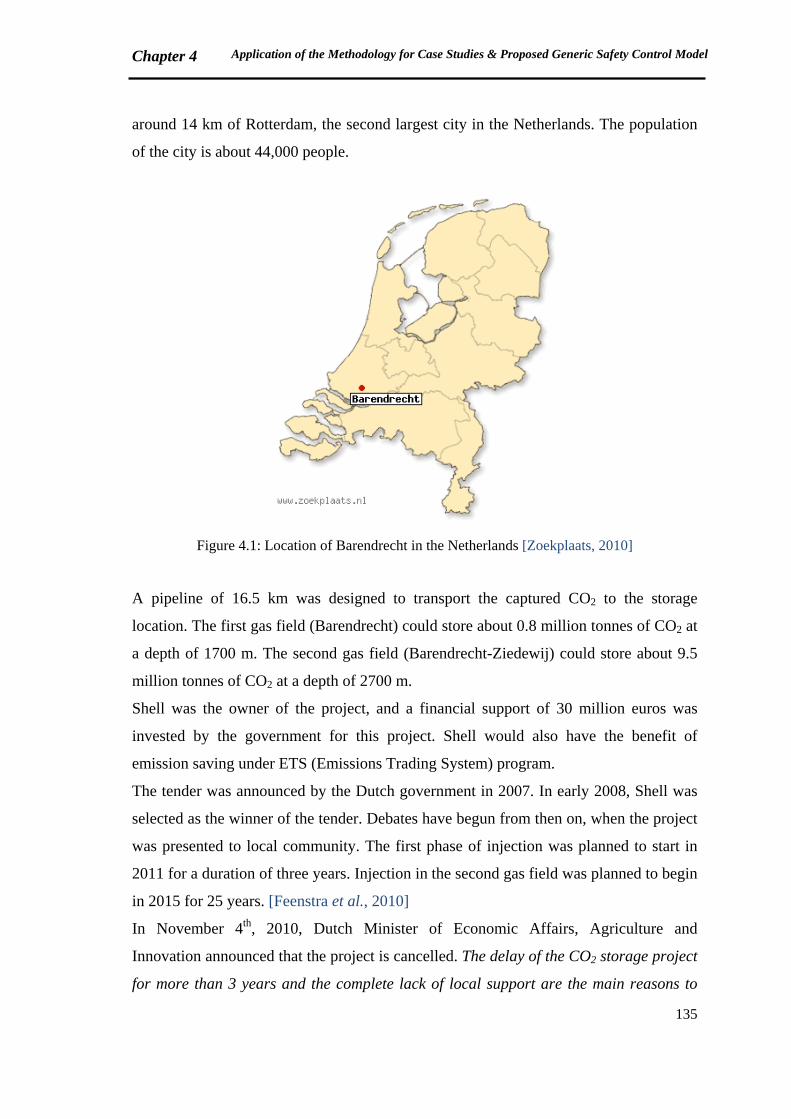
Chapter 4 Application of the Methodology for Case Studies & Proposed Generic Safety Control Model
135
around 14 km of Rotterdam, the second largest city in the Netherlands. The population
of the city is about 44,000 people.
Figure 4.1: Location of Barendrecht in the Netherlands [Zoekplaats, 2010]
A pipeline of 16.5 km was designed to transport the captured CO2 to the storage
location. The first gas field (Barendrecht) could store about 0.8 million tonnes of CO2 at
a depth of 1700 m. The second gas field (Barendrecht-Ziedewij) could store about 9.5
million tonnes of CO2 at a depth of 2700 m.
Shell was the owner of the project, and a financial support of 30 million euros was
invested by the government for this project. Shell would also have the benefit of
emission saving under ETS (Emissions Trading System) program.
The tender was announced by the Dutch government in 2007. In early 2008, Shell was
selected as the winner of the tender. Debates have begun from then on, when the project
was presented to local community. The first phase of injection was planned to start in
2011 for a duration of three years. Injection in the second gas field was planned to begin
in 2015 for 25 years. [Feenstra et al., 2010]
In November 4th, 2010, Dutch Minister of Economic Affairs, Agriculture and
Innovation announced that the project is cancelled. The delay of the CO2 storage project
for more than 3 years and the complete lack of local support are the main reasons to
Chapter 4 Application of the Methodology for Case Studies & Proposed Generic Safety Control Model
136
stop. However, the minister believes that Barendrecht experiences are valuable for
further development of CO2 storage in the Netherlands. So, Barendrecht cancellation
does not mean the end of CO2 storage in the Netherlands. [CCJ, 2010; Netherlands
Government, 2010]
In this section, we will discuss the application of the methodology for Barendrecht
project. The purpose is to understand the weaknesses of the project safety structure, and
the points that could be improved to avoid the delay and stop.
The first two steps of the approach presented in Figure 3.2 are the same as the ones
discussed earlier in section 3.1.2. Therefore, the central point of discussion in this part is
the actors who play a role in the progress of the project.
In the following paragraphs, the main stakeholders and their responsibilities are
summarized [Feenstra et al., 2010]:
‐ National government: was engaged via two ministers: Ministry of Economic Affairs
(EZ) and Ministry of Housing, Spatial Planning and Environment (VROM).
EZ established a group (Task force CCS), with representatives of industry, NGOs
and local governments, to support CTSC development in the Netherlands.
‐ Local governments: were involved at two levels: provincial and municipal.
The executive board of the provincial government was responsible for environmental
permitting procedures. An environmental protection agency (DCMR) was appointed
by the provincial deputy to execute the leadership of a consultation group (BCO2).
BCO2 was the administrative consultation group of Barandrecht project.
At the municipal level, governments of Barendrecht and Albrandswaard were
involved. Albrandswaard population did not raise many concerns about the project,
probably because a few numbers of their houses were located directly above the gas
fields. Barendrecht government was more actively involved.
‐ Project developers: Three companies were engaged. Shell was the initiator and
responsible for storage and monitoring. Two other companies were collaborating
with Shell for capture and transport. NAM (Netherlandse Aardolie Maatschappij
BV), the Netherlands biggest oil and natural gas producer, was responsible for
existing natural gas production from the gas fields in Barendrecht. OCAP (Organic
CO2 for Assimilation of Plants) was responsible for CO2 transport.
Chapter 4 Application of the Methodology for Case Studies & Proposed Generic Safety Control Model
137
‐ External experts, consultants and research organizations: Several external experts
were involved, mainly by project developers, for environmental studies of CO2
storage and to answer the questions from municipality in the public meetings.
‐ NGOs: Several NGOs were also active for or against the project. Greenpeace is
opposed to CTSC, at national and international scales. Uncertainties about
subsurface capacity to store CO2, energy waste, risk of CO2 leakage and
expensiveness are the principal concerns of Greenpeace regarding CTSC technology
[Rochon et al., 2008]. SNM, the Netherlands Society for Nature and Environment,
believes that CTSC is essential as an intermediate step towards clean energy.
‐ Local population: The people who live in the neighborhood of CO2 storage location
are significant stakeholders of CTSC projects. In Barendrecht case, they were
represented by the municipal government.
‐ Media: Local and national newspapers, as well as televisions, websites and
magazines were another actors who were involved in distributing information on the
project.
The organizational structure of Barendrecht project is illustrated in Figure 4.2.
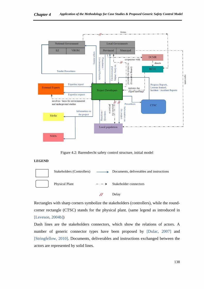
Chapter 4 Application of the Methodology for Case Studies & Proposed Generic Safety Control Model
138
Figure 4.2: Barendrecht safety control structure, initial model
LEGEND
Stakeholders (Controllers)
Documents, deliverables and instructions
Physical Plant
Stakeholder connectors
Delay
Rectangles with sharp corners symbolize the stakeholders (controllers), while the round-
corner rectangle (CTSC) stands for the physical plant. (same legend as introduced in
[Leveson, 2004b])
Dash lines are the stakeholders connectors, which show the relations of actors. A
number of generic connector types have been proposed by [Dulac, 2007] and
[Stringfellow, 2010]. Documents, deliverables and instructions exchanged between the
actors are represented by solid lines.
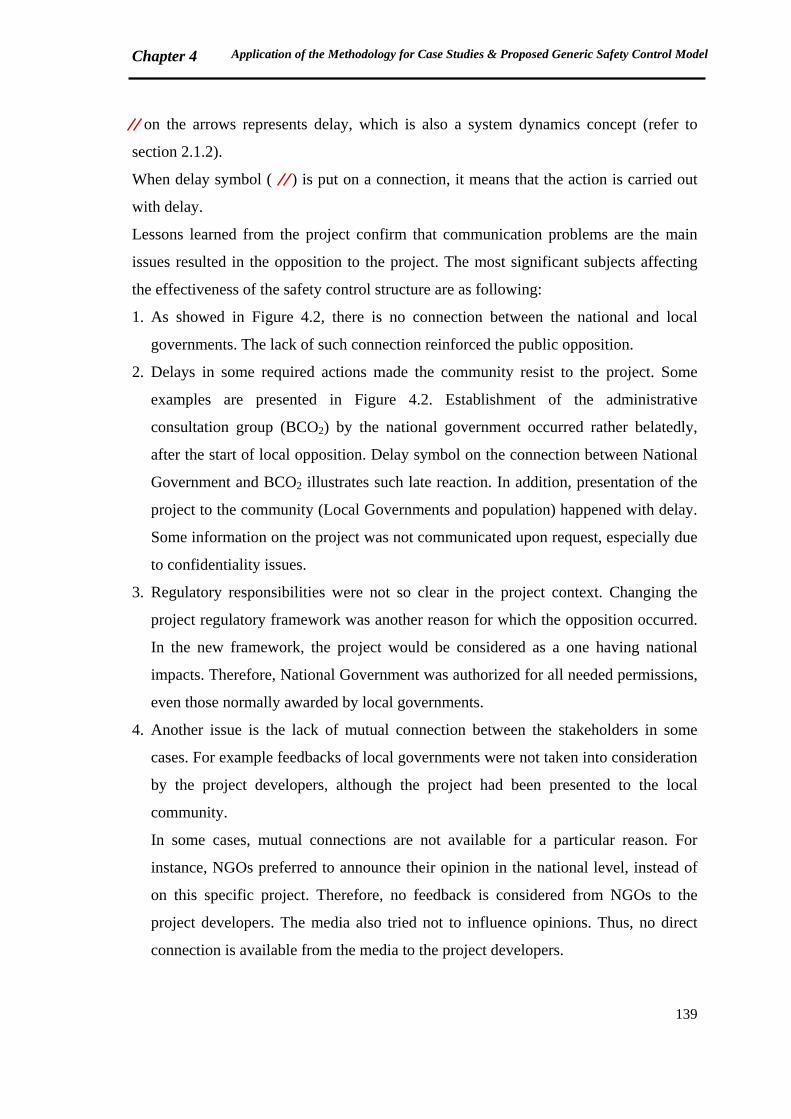
Chapter 4 Application of the Methodology for Case Studies & Proposed Generic Safety Control Model
139
on the arrows represents delay, which is also a system dynamics concept (refer to
section 2.1.2).
When delay symbol ( ) is put on a connection, it means that the action is carried out
with delay.
Lessons learned from the project confirm that communication problems are the main
issues resulted in the opposition to the project. The most significant subjects affecting
the effectiveness of the safety control structure are as following:
1. As showed in Figure 4.2, there is no connection between the national and local
governments. The lack of such connection reinforced the public opposition.
2. Delays in some required actions made the community resist to the project. Some
examples are presented in Figure 4.2. Establishment of the administrative
consultation group (BCO2) by the national government occurred rather belatedly,
after the start of local opposition. Delay symbol on the connection between National
Government and BCO2 illustrates such late reaction. In addition, presentation of the
project to the community (Local Governments and population) happened with delay.
Some information on the project was not communicated upon request, especially due
to confidentiality issues.
3. Regulatory responsibilities were not so clear in the project context. Changing the
project regulatory framework was another reason for which the opposition occurred.
In the new framework, the project would be considered as a one having national
impacts. Therefore, National Government was authorized for all needed permissions,
even those normally awarded by local governments.
4. Another issue is the lack of mutual connection between the stakeholders in some
cases. For example feedbacks of local governments were not taken into consideration
by the project developers, although the project had been presented to the local
community.
In some cases, mutual connections are not available for a particular reason. For
instance, NGOs preferred to announce their opinion in the national level, instead of
on this specific project. Therefore, no feedback is considered from NGOs to the
project developers. The media also tried not to influence opinions. Thus, no direct
connection is available from the media to the project developers.
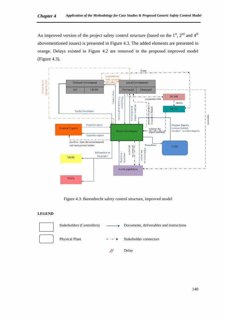
Chapter 4 Application of the Methodology for Case Studies & Proposed Generic Safety Control Model
140
An improved version of the project safety control structure (based on the 1st, 2nd and 4th
abovementioned issues) is presented in Figure 4.3. The added elements are presented in
orange. Delays existed in Figure 4.2 are removed in the proposed improved model
(Figure 4.3).
Figure 4.3: Barendrecht safety control structure, improved model
LEGEND
Stakeholders (Controllers)
Documents, deliverables and instructions
Physical Plant
Stakeholder connectors
Delay
Chapter 4 Application of the Methodology for Case Studies & Proposed Generic Safety Control Model
141
4.1.2 Second example: Lacq
Lacq is a CTSC integrated pilot project in France to inject 120,000 tonnes CO2 in a
depleted gas reservoir (at a depth of 4500 m) during two years. The storage site is
planned to be monitored during three years after the end of injection. Following the
monitoring phase, the responsibility will be transferred to the government. It means that
the project owner will not be responsible after these five years.
CO2 is produced in a natural gas production unit which is situated in Lacq, a city in the
South west of France in Pyrénées-Atlantiques region. An existing pipeline of 29 km
transports CO2 to the injection location, which is located in 3 km of Jurançon city.
Around 7,000 people live in Jurançon (7087 in 2004 [Mairie Jurançon, 2012]). The
Capture plant comes within ICPE regulation. The pipeline and the injection site come
under the mining code.
In February 8, 2007, Total (the project owner) announced the decision of performing
Lacq CTSC pilot plant in a news conference. From 6th to 30th of November 2007 a
public dialogue was taken place to inform the local stakeholders on the project and
understand their points of view and concerns. [C&S Conseils, 2008]
The regional government asked the project owner to conduct a public survey before
giving the permits for the project start-up. A public survey was conducted for 64 days,
from July 21, 2008 to September 22, 2008. A positive opinion on the project was given
by the survey committee (at the end of October 2008) following the results of the
survey.
On May 13, 2009, a decree was published by the regional prefecture to authorize the
start of the project.
The injection was started in January 8, 2010 and planned to be terminated on April
2012. On September 12, 2011, Total requested an extension of 18 months for the
injection, due to the technical problems of some equipment. In April 2011, 23,000
tonnes CO2 was injected into the reservoir, while the objective was to inject 75,000
tonnes CO2. [CLIS, 2011]
The major stakeholders of the project are as follows:
‐ Regional (Local) Government: Several representatives of the regional government
are involved, including the prefects and DRIRE (Direction Régionale de l’Industrie,
Chapter 4 Application of the Methodology for Case Studies & Proposed Generic Safety Control Model
142
de la Recherche et de l’Environnement). Mayors and deputy mayors of different
communities are also engaged.
DRIRE is a French governmental structure which is responsible for controlling the
regulative compliance of the installation in ICPE framework (for ICPE definition,
refer to section 1.6.1.1) [ICPE website 2]. Since January 2010, DRIRE has been
merged with two other structures, DIREN (Direction Régionale de l’Environnement)
and DRE (Direction Régionale de l’Equipement). These three merged structures
form DREAL (Direction Régionale de l’Environnement, de l’Aménagement et du
Logement). DREAL is conducted by the Ministry of Ecology, Energy and
Sustainable Development (MEEDDM: Ministère de l’Ecologie, de l’Energie, du
Développement Durable et de la Mer).
A local committee (CLIS: Commission Locale d’Information et de Suivi) has been
created by the regional prefecture to follow up the project progress. Regular meetings
have been held since June 2008, when CLIS was established.
‐ Project Owner: Total is the owner of the project. Some other companies cooperate
with Total, such as Air Liquide for the oxycombustion unit.
‐ External experts: from universities and research organizations have been requested to
verify whether there are significant environmental and health risks concerning the
project. If so, preventive and protective barriers for the potential risks were asked to
be identified. The experts also seek to improve their knowledge on the possibility of
commercial scale CTSC projects in France.
‐ NGOs: Several environmental NGOs have participated in the debates since the first
public presentation of the project. An external specialist was asked by one of the
NGOs to evaluate the project. Having one single private firm (Total) as the owner of
the project is a main issue raised by the expert. He believes that for such a project,
which has a life cycle much more than the company’s life cycle, organizations
working on long term monitoring and risk management have to contribute. [CLIS,
2008]
‐ Local population: is again a main stakeholder of the project.
‐ Media: Local and national newspapers and websites spread the information
concerning the project.
The organizational structure of Lacq project is illustrated in Figure 4.4.
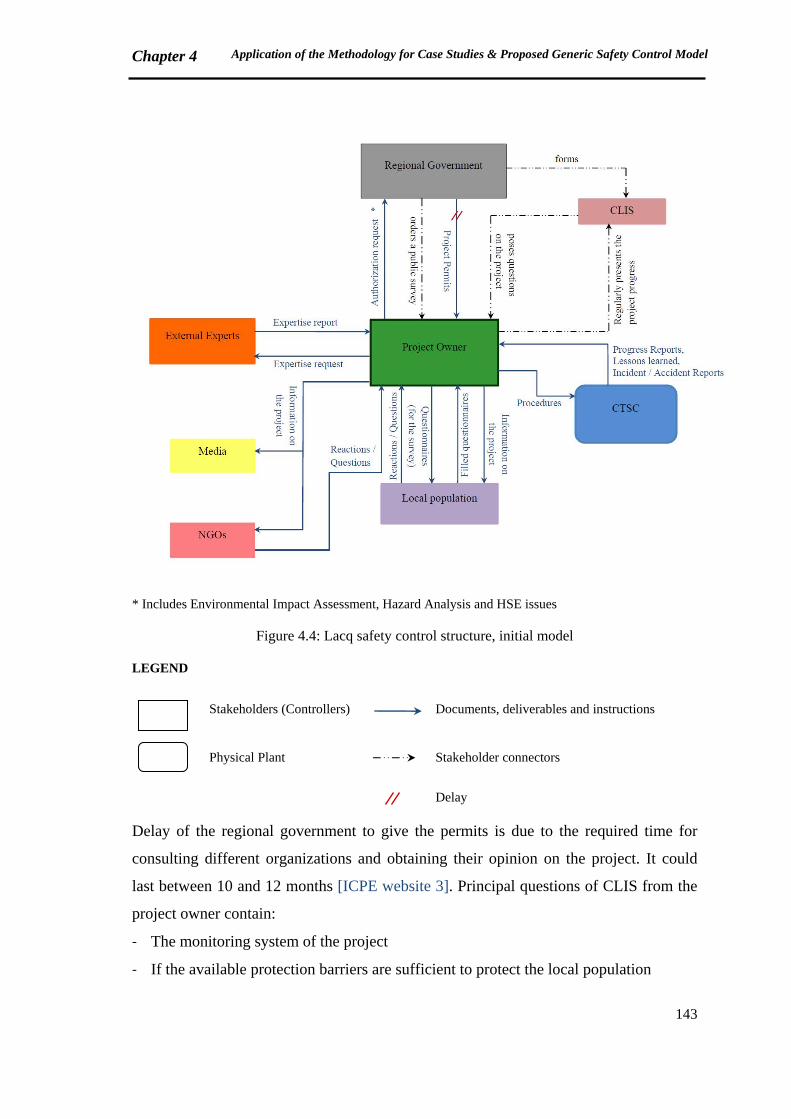
Chapter 4 Application of the Methodology for Case Studies & Proposed Generic Safety Control Model
143
* Includes Environmental Impact Assessment, Hazard Analysis and HSE issues
Figure 4.4: Lacq safety control structure, initial model
LEGEND
Stakeholders (Controllers)
Documents, deliverables and instructions
Physical Plant
Stakeholder connectors
Delay
Delay of the regional government to give the permits is due to the required time for
consulting different organizations and obtaining their opinion on the project. It could
last between 10 and 12 months [ICPE website 3]. Principal questions of CLIS from the
project owner contain:
‐ The monitoring system of the project
‐ If the available protection barriers are sufficient to protect the local population
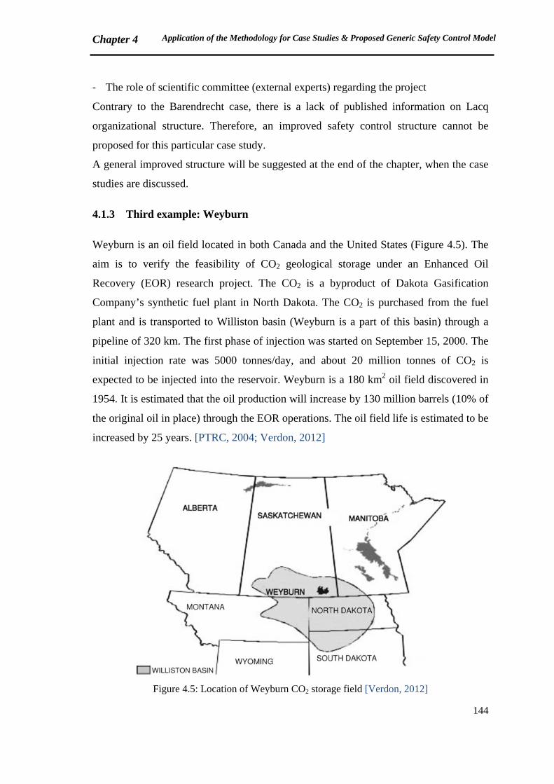
Chapter 4 Application of the Methodology for Case Studies & Proposed Generic Safety Control Model
144
‐ The role of scientific committee (external experts) regarding the project
Contrary to the Barendrecht case, there is a lack of published information on Lacq
organizational structure. Therefore, an improved safety control structure cannot be
proposed for this particular case study.
A general improved structure will be suggested at the end of the chapter, when the case
studies are discussed.
4.1.3 Third example: Weyburn
Weyburn is an oil field located in both Canada and the United States (Figure 4.5). The
aim is to verify the feasibility of CO2 geological storage under an Enhanced Oil
Recovery (EOR) research project. The CO2 is a byproduct of Dakota Gasification
Company’s synthetic fuel plant in North Dakota. The CO2 is purchased from the fuel
plant and is transported to Williston basin (Weyburn is a part of this basin) through a
pipeline of 320 km. The first phase of injection was started on September 15, 2000. The
initial injection rate was 5000 tonnes/day, and about 20 million tonnes of CO2 is
expected to be injected into the reservoir. Weyburn is a 180 km2 oil field discovered in
1954. It is estimated that the oil production will increase by 130 million barrels (10% of
the original oil in place) through the EOR operations. The oil field life is estimated to be
increased by 25 years. [PTRC, 2004; Verdon, 2012]
Figure 4.5: Location of Weyburn CO2 storage field [Verdon, 2012]
Chapter 4 Application of the Methodology for Case Studies & Proposed Generic Safety Control Model
145
The project was launched by PTRC (Petroleum Technology Research Center), in
Regina, Saskatchewan, in collaboration with Encana (now Cenovus) in Calgary,
Alberta. The fund is provided by several governments and industries of Canada, the
United States, Europe and Japan. [PTRC, 2004]
In January 2011, a farmer couple, having their land over the Weyburn CO2 storage site,
claimed that the injected CO2 has been leaked, killed animals and sent groundwater
foaming to the surface like shaken-up soda-pop. They asked a consultant (Petro-Find)
for a soil gas study. The results showed that the source of CO2 high concentrations in
the soil is the injected CO2 into the Weyburn reservoir. [CBC news, 2011]
PTRC and Cenovus, the project owners, called for an independent expertise. They
announced that no leakage has been identified in the Weyburn field, and the source of
CO2 claimed by the farmers is not the Weyburn reservoir [Whittaker, 2011]. However,
Ecojustice (a Canadian Environmental NGO) claims that there are important
unanswered questions in PTRC response to the soil gas studies [Ecojustice, 2011]. In
March 2011, Petro-Find performed another soil gas survey, and confirmed that the
source of CO2 found in the soil gas is the anthropogenic CO2 injected into the Weyburn
reservoir [Lafleur, 2011].
In spite of debates on the leakage, the project is still in operation [GCCSI website,
2012].
Details on Weyburn project stakeholders are not available. The following structure
(Figure 4.6) is prepared based on [CCP, 2012], which is an industry point of view of
stakeholders.
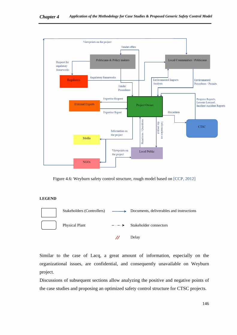
Chapter 4 Application of the Methodology for Case Studies & Proposed Generic Safety Control Model
146
Figure 4.6: Weyburn safety control structure, rough model based on [CCP, 2012]
LEGEND
Stakeholders (Controllers)
Documents, deliverables and instructions
Physical Plant
Stakeholder connectors
Delay
Similar to the case of Lacq, a great amount of information, especially on the
organizational issues, are confidential, and consequently unavailable on Weyburn
project.
Discussions of subsequent sections allow analyzing the positive and negative points of
the case studies and proposing an optimized safety control structure for CTSC projects.
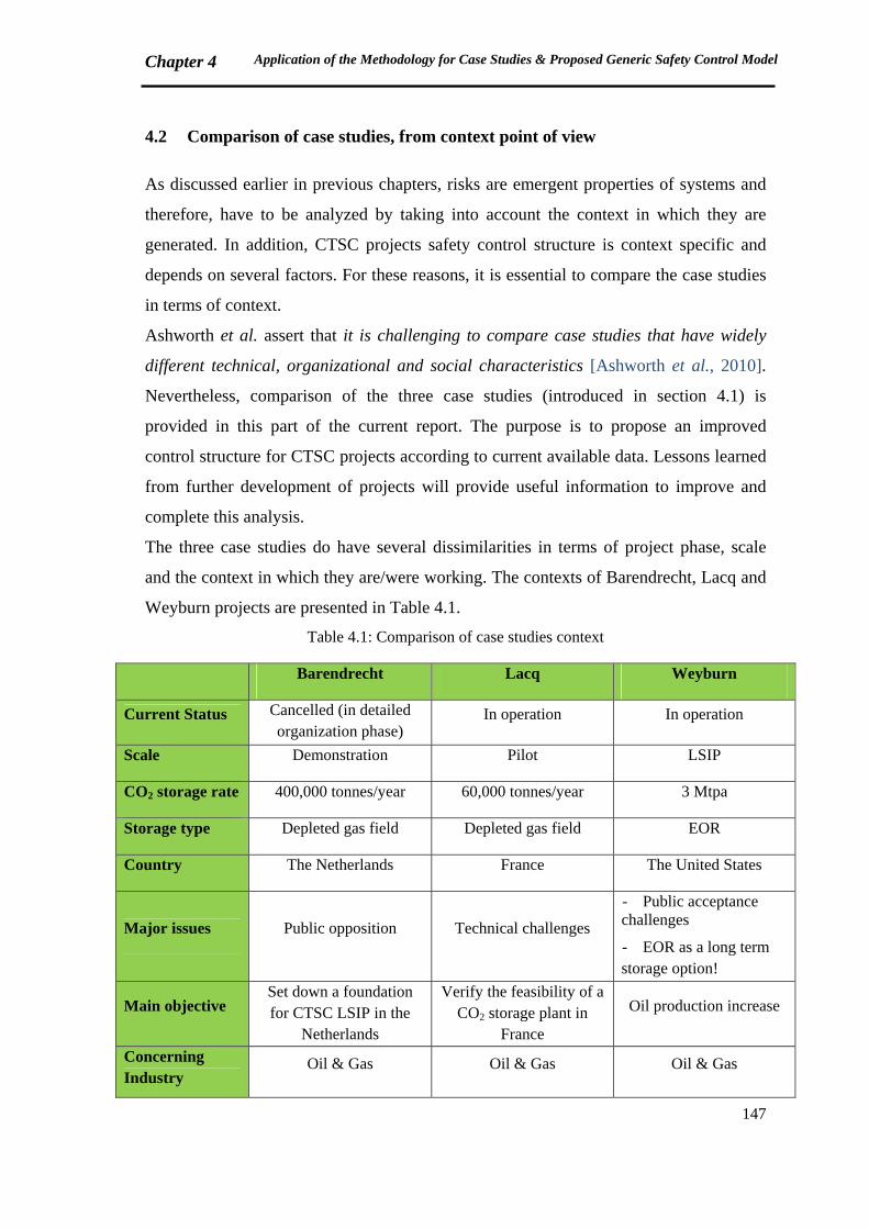
Chapter 4 Application of the Methodology for Case Studies & Proposed Generic Safety Control Model
147
4.2 Comparison of case studies, from context point of view
As discussed earlier in previous chapters, risks are emergent properties of systems and
therefore, have to be analyzed by taking into account the context in which they are
generated. In addition, CTSC projects safety control structure is context specific and
depends on several factors. For these reasons, it is essential to compare the case studies
in terms of context.
Ashworth et al. assert that it is challenging to compare case studies that have widely
different technical, organizational and social characteristics [Ashworth et al., 2010].
Nevertheless, comparison of the three case studies (introduced in section 4.1) is
provided in this part of the current report. The purpose is to propose an improved
control structure for CTSC projects according to current available data. Lessons learned
from further development of projects will provide useful information to improve and
complete this analysis.
The three case studies do have several dissimilarities in terms of project phase, scale
and the context in which they are/were working. The contexts of Barendrecht, Lacq and
Weyburn projects are presented in Table 4.1.
Table 4.1: Comparison of case studies context
Barendrecht Lacq Weyburn
Current Status Cancelled (in detailed organization phase)
In operation In operation
Scale Demonstration Pilot LSIP
CO2 storage rate 400,000 tonnes/year 60,000 tonnes/year 3 Mtpa
Storage type Depleted gas field Depleted gas field EOR
Country The Netherlands France The United States
Major issues Public opposition Technical challenges
- Public acceptance challenges
- EOR as a long term storage option!
Main objective Set down a foundation for CTSC LSIP in the
Netherlands
Verify the feasibility of a CO2 storage plant in
France
Oil production increase
Concerning Industry
Oil & Gas Oil & Gas Oil & Gas
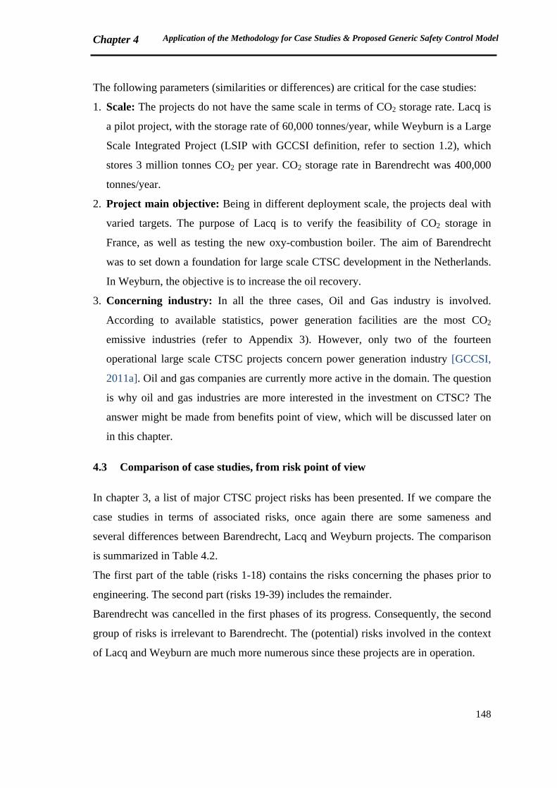
Chapter 4 Application of the Methodology for Case Studies & Proposed Generic Safety Control Model
148
The following parameters (similarities or differences) are critical for the case studies:
1. Scale: The projects do not have the same scale in terms of CO2 storage rate. Lacq is
a pilot project, with the storage rate of 60,000 tonnes/year, while Weyburn is a Large
Scale Integrated Project (LSIP with GCCSI definition, refer to section 1.2), which
stores 3 million tonnes CO2 per year. CO2 storage rate in Barendrecht was 400,000
tonnes/year.
2. Project main objective: Being in different deployment scale, the projects deal with
varied targets. The purpose of Lacq is to verify the feasibility of CO2 storage in
France, as well as testing the new oxy-combustion boiler. The aim of Barendrecht
was to set down a foundation for large scale CTSC development in the Netherlands.
In Weyburn, the objective is to increase the oil recovery.
3. Concerning industry: In all the three cases, Oil and Gas industry is involved.
According to available statistics, power generation facilities are the most CO2
emissive industries (refer to Appendix 3). However, only two of the fourteen
operational large scale CTSC projects concern power generation industry [GCCSI,
2011a]. Oil and gas companies are currently more active in the domain. The question
is why oil and gas industries are more interested in the investment on CTSC? The
answer might be made from benefits point of view, which will be discussed later on
in this chapter.
4.3 Comparison of case studies, from risk point of view
In chapter 3, a list of major CTSC project risks has been presented. If we compare the
case studies in terms of associated risks, once again there are some sameness and
several differences between Barendrecht, Lacq and Weyburn projects. The comparison
is summarized in Table 4.2.
The first part of the table (risks 1-18) contains the risks concerning the phases prior to
engineering. The second part (risks 19-39) includes the remainder.
Barendrecht was cancelled in the first phases of its progress. Consequently, the second
group of risks is irrelevant to Barendrecht. The (potential) risks involved in the context
of Lacq and Weyburn are much more numerous since these projects are in operation.
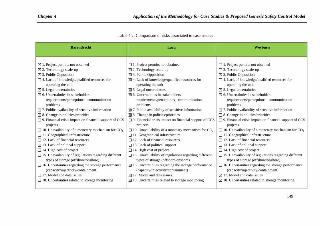
Chapter 4 Application of the Methodology for Case Studies & Proposed Generic Safety Control Model
149
Table 4.2: Comparison of risks associated to case studies
Barendrecht Lacq Weyburn
1. Project permits not obtained 2. Technology scale-up 3. Public Opposition 4. Lack of knowledge/qualified resources for
operating the unit 5. Legal uncertainties 6. Uncertainties in stakeholders
requirements/perceptions - communication problems
7. Public availability of sensitive information 8. Change in policies/priorities 9. Financial crisis impact on financial support of CCS
projects 10. Unavailability of a monetary mechanism for CO2 11. Geographical infrastructure 12. Lack of financial resources 13. Lack of political support 14. High cost of project 15. Unavailability of regulations regarding different
types of storage (offshore/onshore) 16. Uncertainties regarding the storage performance
(capacity/injectivity/containment) 17. Model and data issues 18. Uncertainties related to storage monitoring
Chapter 4 Application of the Methodology for Case Studies & Proposed Generic Safety Control Model
150
Table 4.2: Comparison of risks associated to case studies, continued
Barendrecht Lacq Weyburn
19. Corrosion 20. Using the existing facilities (specially pipelines) 21. CO2 out of specification 22. CO2 plumes exceed the safe zone 23. Safety related accident 24. Construction field conditions 25. Proximity to other industrial plants 26. Energy consumption 27. Maintenance and control procedures (including
ESD system) 28. BLEVE 29. Phase change & material problems 30. Lower Capture efficiency due to the upstream
plant flexible operation 31. CO2 leakage from compression unit 32. Pipeline construction 33. CO2 leakage from pipeline 34. Leakage through manmade pathways such as
abandoned wells 35. Well integrity 36. CO2 migration 37. Injectivity reduction over time 38. CO2 leakage from storage to the surface 39. Soil contamination
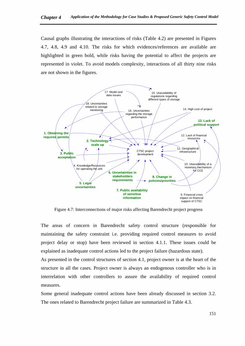
Chapter 4 Application of the Methodology for Case Studies & Proposed Generic Safety Control Model
151
Causal graphs illustrating the interactions of risks (Table 4.2) are presented in Figures
4.7, 4.8, 4.9 and 4.10. The risks for which evidences/references are available are
highlighted in green bold, while risks having the potential to affect the projects are
represented in violet. To avoid models complexity, interactions of all thirty nine risks
are not shown in the figures.
CTSC projectdevelopment
1. Obtaining therequired permits
+
2. Technologyscale up
+3. Public
acceptation+
4. Knowledge/Resourcesfor operating the unit
+
5. Legaluncertainties
6. Uncertainties instakeholdersrequirements
7. Public availabilityof sensitiveinformation
8. Change inpolicies/priorities
9. Financial crisisimpact on financialsupport of CTSC
10. Unavailability of amonetary mechanism
for CO2
11. Geographicalinfrastructure
12. Lack of financialresources
13. Lack ofpolitical support
14. High cost of project
15. Unavailability ofregulations regarding
different types of storage
16. Uncertaintiesregarding the storage
performance
17. Model anddata issues
18. Uncertaintiesrelated to storage
monitoring
--
--
+
------- +
+
-
- +
+
-
--
+
Figure 4.7: Interconnections of major risks affecting Barendrecht project progress
The areas of concern in Barendrecht safety control structure (responsible for
maintaining the safety constraint i.e. providing required control measures to avoid
project delay or stop) have been reviewed in section 4.1.1. These issues could be
explained as inadequate control actions led to the project failure (hazardous state).
As presented in the control structures of section 4.1, project owner is at the heart of the
structure in all the cases. Project owner is always an endogenous controller who is in
interrelation with other controllers to assure the availability of required control
measures.
Some general inadequate control actions have been already discussed in section 3.2.
The ones related to Barendrecht project failure are summarized in Table 4.3.
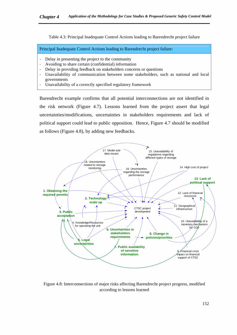
Chapter 4 Application of the Methodology for Case Studies & Proposed Generic Safety Control Model
152
Table 4.3: Principal Inadequate Control Actions leading to Barendrecht project failure
Principal Inadequate Control Actions leading to Barendrecht project failure:
‐ Delay in presenting the project to the community ‐ Avoiding to share certain (confidential) information ‐ Delay in providing feedback on stakeholders concerns or questions ‐ Unavailability of communication between some stakeholders, such as national and local
governments ‐ Unavailability of a correctly specified regulatory framework
Barendrecht example confirms that all potential interconnections are not identified in
the risk network (Figure 4.7). Lessons learned from the project assert that legal
uncertainties/modifications, uncertainties in stakeholders requirements and lack of
political support could lead to public opposition. Hence, Figure 4.7 should be modified
as follows (Figure 4.8), by adding new feedbacks.
CTSC projectdevelopment
1. Obtaining therequired permits
+
2. Technologyscale up
+
3. Publicacceptation
+
4. Knowledge/Resourcesfor operating the unit
+
5. Legaluncertainties
6. Uncertainties instakeholdersrequirements
7. Public availabilityof sensitiveinformation
8. Change inpolicies/priorities
9. Financial crisisimpact on financialsupport of CTSC
10. Unavailability of amonetary mechanism
for CO2
11. Geographicalinfrastructure
12. Lack of financialresources
13. Lack ofpolitical support
14. High cost of project
15. Unavailability ofregulations regarding
different types of storage
16. Uncertaintiesregarding the storage
performance
17. Model anddata issues
18. Uncertaintiesrelated to storage
monitoring
--
--
+
------- +
+
-
-+
+
-
--
+
- --
Figure 4.8: Interconnections of major risks affecting Barendrecht project progress, modified according to lessons learned
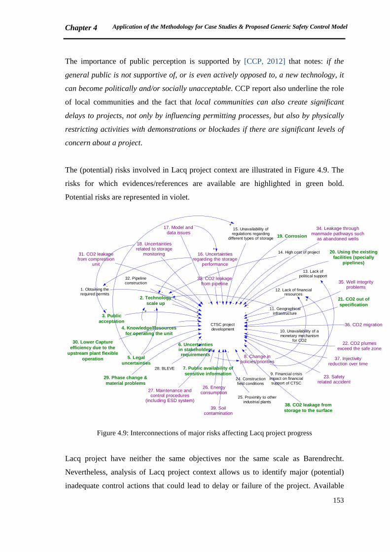
Chapter 4 Application of the Methodology for Case Studies & Proposed Generic Safety Control Model
153
The importance of public perception is supported by [CCP, 2012] that notes: if the
general public is not supportive of, or is even actively opposed to, a new technology, it
can become politically and/or socially unacceptable. CCP report also underline the role
of local communities and the fact that local communities can also create significant
delays to projects, not only by influencing permitting processes, but also by physically
restricting activities with demonstrations or blockades if there are significant levels of
concern about a project.
The (potential) risks involved in Lacq project context are illustrated in Figure 4.9. The
risks for which evidences/references are available are highlighted in green bold.
Potential risks are represented in violet.
CTSC projectdevelopment
1. Obtaining therequired permits
+
2. Technologyscale up
+3. Publicacceptation +
4. Knowledge/Resourcesfor operating the unit
+
5. Legaluncertainties
6. Uncertaintiesin stakeholdersrequirements
7. Public availability ofsensitive information
8. Change inpolicies/priorities
9. Financial crisisimpact on financialsupport of CTSC
10. Unavailability of amonetary mechanism
for CO2
11. Geographicalinfrastructure
12. Lack of financialresources
13. Lack ofpolitical support
14. High cost of project
15. Unavailability ofregulations regarding
different types of storage
16. Uncertaintiesregarding the storage
performance
17. Model anddata issues
18. Uncertaintiesrelated to storage
monitoring
-
--
-
+
--
-----+
+
-
- +
+
-
--
+
19. Corrosion
-
20. Using the existingfacilities (specially
pipelines)
-21. CO2 out ofspecification
-
22. CO2 plumesexceed the safe zone
-
23. Safetyrelated accident
-
24. Constructionfield conditions
25. Proximity to otherindustrial plants
-
26. Energyconsumption27. Maintenance and
control procedures(including ESD system)
28. BLEVE
-
29. Phase change &material problems
-30. Lower Capture
efficiency due to theupstream plant flexible
operation
-
31. CO2 leakagefrom compression
unit
-
32. Pipelineconstruction
33. CO2 leakagefrom pipeline
-
34. Leakage throughmanmade pathways such
as abandoned wells
-
35. Well integrityproblems
-36. CO2 migration-
37. Injectivityreduction over time
-
38. CO2 leakage fromstorage to the surface
-
39. Soilcontamination
-
Figure 4.9: Interconnections of major risks affecting Lacq project progress
Lacq project have neither the same objectives nor the same scale as Barendrecht.
Nevertheless, analysis of Lacq project context allows us to identify major (potential)
inadequate control actions that could lead to delay or failure of the project. Available
Chapter 4 Application of the Methodology for Case Studies & Proposed Generic Safety Control Model
154
information and lessons learned from the project provide us with some inadequate
control actions resulted in project delay. Some of the inadequate control actions might
be justified by the fact that the project is in pilot scale, and technical challenges are
indispensable for verifying CTSC feasibility in this scale. Since the project is not
terminated, potential inadequate control actions could be also envisaged (Table 4.4).
Table 4.4: Principal (Potential) Inadequate Control Actions leading to Lacq project delay or failure
Principal Inadequate Control Actions leading to Lacq project delay:
‐ Underestimation of feed impurities that could result in corrosion ‐ Using some existing facilities which are not appropriate for the current application ‐ Having to send forth the CO2 into the atmosphere as a result of technical problems
Principal Potential Inadequate Control Actions leading to Lacq project delay or failure:
‐ Avoiding to share certain (confidential) information ‐ Avoiding to take the effects of using existing facilities into consideration
Figure 4.10 illustrates the (potential) risks associated to Weyburn project. Same as the
previous cases, the risks for which evidences/references are available are highlighted in
green bold. Potential risks are represented in violet.
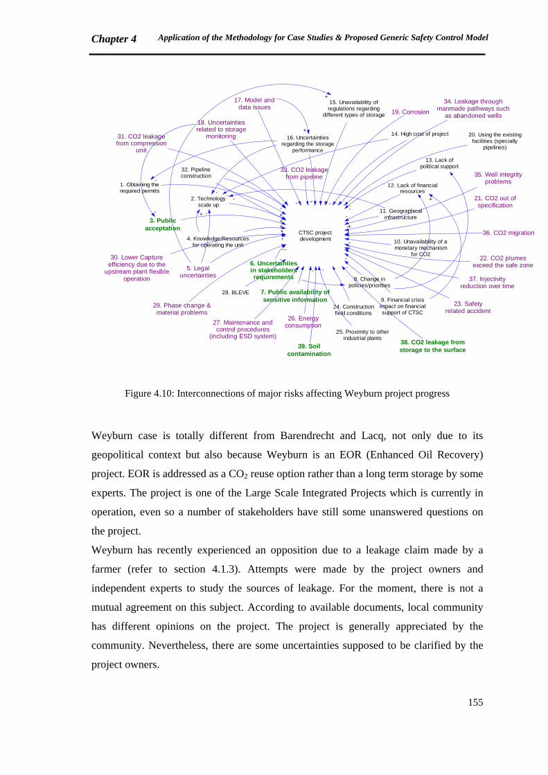
Chapter 4 Application of the Methodology for Case Studies & Proposed Generic Safety Control Model
155
CTSC projectdevelopment
1. Obtaining therequired permits
+
2. Technologyscale up
+3. Publicacceptation +
4. Knowledge/Resourcesfor operating the unit
+
5. Legaluncertainties
6. Uncertaintiesin stakeholdersrequirements
7. Public availability ofsensitive information
8. Change inpolicies/priorities
9. Financial crisisimpact on financialsupport of CTSC
10. Unavailability of amonetary mechanism
for CO2
11. Geographicalinfrastructure
12. Lack of financialresources
13. Lack ofpolitical support
14. High cost of project
15. Unavailability ofregulations regarding
different types of storage
16. Uncertaintiesregarding the storage
performance
17. Model anddata issues
18. Uncertaintiesrelated to storage
monitoring
-
-
-
-
+
--
-----+
+
-
- +
+
-
--
+
19. Corrosion
-
20. Using the existingfacilities (specially
pipelines)
-21. CO2 out ofspecification
-
22. CO2 plumesexceed the safe zone
-
23. Safetyrelated accident
-
24. Constructionfield conditions
25. Proximity to otherindustrial plants
-
26. Energyconsumption27. Maintenance and
control procedures(including ESD system)
28. BLEVE
-
29. Phase change &material problems
-
30. Lower Captureefficiency due to the
upstream plant flexibleoperation
-
31. CO2 leakagefrom compression
unit
-
32. Pipelineconstruction
33. CO2 leakagefrom pipeline
-
34. Leakage throughmanmade pathways such
as abandoned wells
-
35. Well integrityproblems
-36. CO2 migration-
37. Injectivityreduction over time
-
38. CO2 leakage fromstorage to the surface
-
39. Soilcontamination
-
Figure 4.10: Interconnections of major risks affecting Weyburn project progress
Weyburn case is totally different from Barendrecht and Lacq, not only due to its
geopolitical context but also because Weyburn is an EOR (Enhanced Oil Recovery)
project. EOR is addressed as a CO2 reuse option rather than a long term storage by some
experts. The project is one of the Large Scale Integrated Projects which is currently in
operation, even so a number of stakeholders have still some unanswered questions on
the project.
Weyburn has recently experienced an opposition due to a leakage claim made by a
farmer (refer to section 4.1.3). Attempts were made by the project owners and
independent experts to study the sources of leakage. For the moment, there is not a
mutual agreement on this subject. According to available documents, local community
has different opinions on the project. The project is generally appreciated by the
community. Nevertheless, there are some uncertainties supposed to be clarified by the
project owners.
Chapter 4 Application of the Methodology for Case Studies & Proposed Generic Safety Control Model
156
Mayor of Weyburn, who has a deep familial connection to the city, is a proponent of the
project. She considers Weyburn CTSC project as an opportunity for the community.
She defends her idea by highlighting employment opportunities and rise in real estate
business costs as positive effects of the project. The mayor believes that no safety risk is
probable in long term according to the researches. Natural resources (coal) and available
knowledge (on oil and gas industry) are additional points that make Weyburn an
appropriate location for CO2 storage experience [CCS101, 2009a].
On the other hand, the reeve of Weyburn rural municipality is cautiously optimistic
about the project. As well as the mayor, she has a farm family with an ancient familial
background in Weyburn area. In spite of being optimistic about the project, she is
cautious because she doesn’t feel that she knows a lot about the long term effects. There
are still some unknown factors. The reeve makes reference to a panel organized by
PTRC. She affirms that they maybe don’t have the answers that people want for those
questions on long term risks. Therefore, it is not currently obvious whether the gains
from the project are short term or long term. Even if some people will come to Weyburn
for working in the industry, others may leave the region because of the CO2 storage
project. The positive points are the economic drivers and benefits such as recovering oil
(which will lead to expand high additional employees), media attention and tourism
increase. Nevertheless, she (as both a local administration officer and a farmer) has
several personal concerns. She believes that Weyburn does rely on oil, although
agriculture is another important industry in Weyburn. Her concerns include:
‐ Impact of the storage on land values
‐ Impact of the storage on water systems
‐ Impact of the storage on live stock
‐ Impact of the storage on land production performance
And she doubts whether Weyburn project is a long term storage facility since oil is
recovered as a result. [CCS101, 2009b]
These expressions attest that each stakeholder is seeking for his own individual benefits
in CTSC project development. Searching for benefits (especially short-term benefits)
explain why oil and gas industry is currently investing more on CTSC technologies.
Being an EOR project is a critical factor of success for Weyburn. GCCSI confirms that
EOR is a significant CO2 reuse option which has a substantial contribution to CTSC
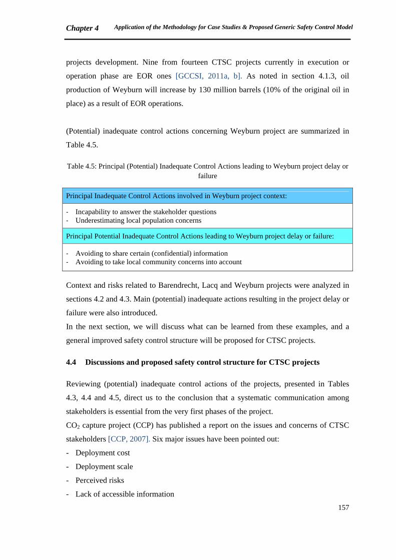
Chapter 4 Application of the Methodology for Case Studies & Proposed Generic Safety Control Model
157
projects development. Nine from fourteen CTSC projects currently in execution or
operation phase are EOR ones [GCCSI, 2011a, b]. As noted in section 4.1.3, oil
production of Weyburn will increase by 130 million barrels (10% of the original oil in
place) as a result of EOR operations.
(Potential) inadequate control actions concerning Weyburn project are summarized in
Table 4.5.
Table 4.5: Principal (Potential) Inadequate Control Actions leading to Weyburn project delay or failure
Principal Inadequate Control Actions involved in Weyburn project context:
‐ Incapability to answer the stakeholder questions ‐ Underestimating local population concerns
Principal Potential Inadequate Control Actions leading to Weyburn project delay or failure:
‐ Avoiding to share certain (confidential) information ‐ Avoiding to take local community concerns into account
Context and risks related to Barendrecht, Lacq and Weyburn projects were analyzed in
sections 4.2 and 4.3. Main (potential) inadequate actions resulting in the project delay or
failure were also introduced.
In the next section, we will discuss what can be learned from these examples, and a
general improved safety control structure will be proposed for CTSC projects.
4.4 Discussions and proposed safety control structure for CTSC projects
Reviewing (potential) inadequate control actions of the projects, presented in Tables
4.3, 4.4 and 4.5, direct us to the conclusion that a systematic communication among
stakeholders is essential from the very first phases of the project.
CO2 capture project (CCP) has published a report on the issues and concerns of CTSC
stakeholders [CCP, 2007]. Six major issues have been pointed out:
- Deployment cost
- Deployment scale
- Perceived risks
- Lack of accessible information
Chapter 4 Application of the Methodology for Case Studies & Proposed Generic Safety Control Model
158
- Supporting policies
- Adequacy of regulatory frameworks
Perceptions of several stakeholders from different geographical zones (Australia and
New Zealand, North America, Europe, Japan, China, India and South Africa) are
presented in this report. The stakeholders include:
- Research and Development organizations
- Industry
- Government
- NGOs
- General public
The results confirm that most of the stakeholders are worried about cost of deployment,
deployment scale, impact on drinking water, accessibility of information according to
the stakeholders requirements and adequacy of regulatory frameworks in North
America. However, concerns of stakeholders in Europe are much more less than the
North American ones. Regulatory issues are at the top of European stakeholders
considerations. Most of the concerns have been raised by NGOs, both in North America
and Europe.
The most challenging points on which there are strong difference of opinions within
stakeholder groups include:
- Stakeholder perceptions on CTSC as a bridging technology
- Impact of EOR on oil market extension
- Impact of CTSC on coal market extension
- Effect on investments on other energy sources such as renewables and nuclear
- Contribution of CTSC to CO2 emissions reduction in short term
- Inadequacy of efforts for communication
- Cost of deployment
These points have been mostly raised in North America. [CCP, 2007]
A report has been recently published by CO2 Capture Project (CCP). Different case
studies and publications have been reviewed in order to identify the concerns of
stakeholders. CCP mentions that most of CTSC case studies relate to oil and gas
industry rather than power generation. Therefore findings are based on oil and gas
sector stakeholder viewpoints. According to [CCP, 2012], policy makers, local
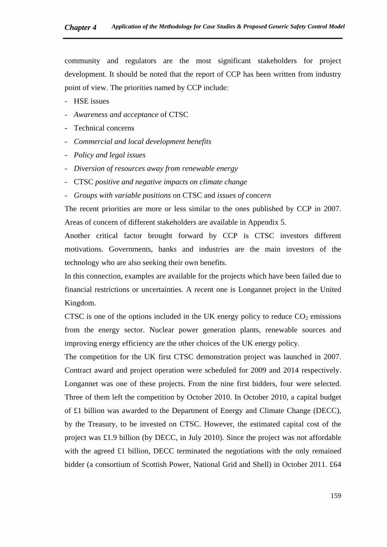
Chapter 4 Application of the Methodology for Case Studies & Proposed Generic Safety Control Model
159
community and regulators are the most significant stakeholders for project
development. It should be noted that the report of CCP has been written from industry
point of view. The priorities named by CCP include:
- HSE issues
- Awareness and acceptance of CTSC
- Technical concerns
- Commercial and local development benefits
- Policy and legal issues
- Diversion of resources away from renewable energy
- CTSC positive and negative impacts on climate change
- Groups with variable positions on CTSC and issues of concern
The recent priorities are more or less similar to the ones published by CCP in 2007.
Areas of concern of different stakeholders are available in Appendix 5.
Another critical factor brought forward by CCP is CTSC investors different
motivations. Governments, banks and industries are the main investors of the
technology who are also seeking their own benefits.
In this connection, examples are available for the projects which have been failed due to
financial restrictions or uncertainties. A recent one is Longannet project in the United
Kingdom.
CTSC is one of the options included in the UK energy policy to reduce CO2 emissions
from the energy sector. Nuclear power generation plants, renewable sources and
improving energy efficiency are the other choices of the UK energy policy.
The competition for the UK first CTSC demonstration project was launched in 2007.
Contract award and project operation were scheduled for 2009 and 2014 respectively.
Longannet was one of these projects. From the nine first bidders, four were selected.
Three of them left the competition by October 2010. In October 2010, a capital budget
of £1 billion was awarded to the Department of Energy and Climate Change (DECC),
by the Treasury, to be invested on CTSC. However, the estimated capital cost of the
project was £1.9 billion (by DECC, in July 2010). Since the project was not affordable
with the agreed £1 billion, DECC terminated the negotiations with the only remained
bidder (a consortium of Scottish Power, National Grid and Shell) in October 2011. £64
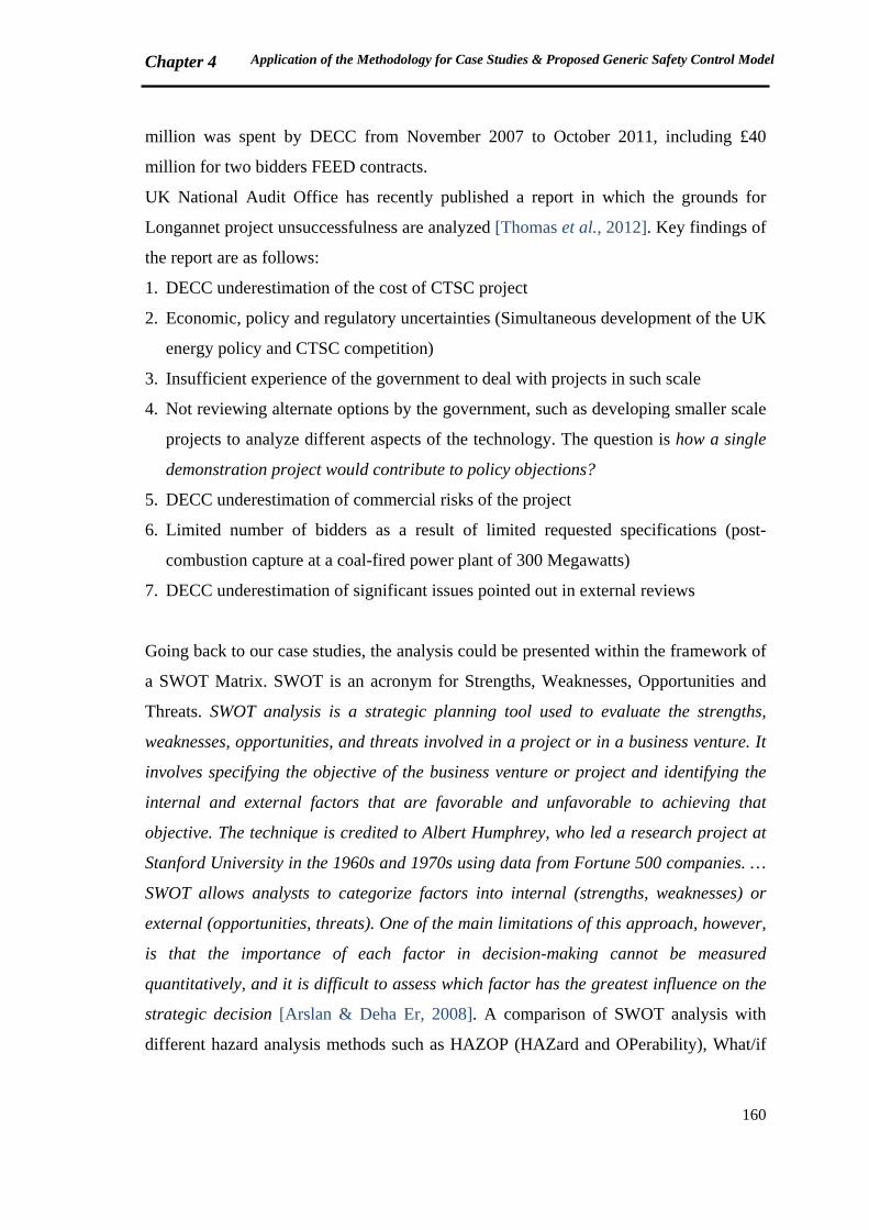
Chapter 4 Application of the Methodology for Case Studies & Proposed Generic Safety Control Model
160
million was spent by DECC from November 2007 to October 2011, including £40
million for two bidders FEED contracts.
UK National Audit Office has recently published a report in which the grounds for
Longannet project unsuccessfulness are analyzed [Thomas et al., 2012]. Key findings of
the report are as follows:
1. DECC underestimation of the cost of CTSC project
2. Economic, policy and regulatory uncertainties (Simultaneous development of the UK
energy policy and CTSC competition)
3. Insufficient experience of the government to deal with projects in such scale
4. Not reviewing alternate options by the government, such as developing smaller scale
projects to analyze different aspects of the technology. The question is how a single
demonstration project would contribute to policy objections?
5. DECC underestimation of commercial risks of the project
6. Limited number of bidders as a result of limited requested specifications (post-
combustion capture at a coal-fired power plant of 300 Megawatts)
7. DECC underestimation of significant issues pointed out in external reviews
Going back to our case studies, the analysis could be presented within the framework of
a SWOT Matrix. SWOT is an acronym for Strengths, Weaknesses, Opportunities and
Threats. SWOT analysis is a strategic planning tool used to evaluate the strengths,
weaknesses, opportunities, and threats involved in a project or in a business venture. It
involves specifying the objective of the business venture or project and identifying the
internal and external factors that are favorable and unfavorable to achieving that
objective. The technique is credited to Albert Humphrey, who led a research project at
Stanford University in the 1960s and 1970s using data from Fortune 500 companies. …
SWOT allows analysts to categorize factors into internal (strengths, weaknesses) or
external (opportunities, threats). One of the main limitations of this approach, however,
is that the importance of each factor in decision-making cannot be measured
quantitatively, and it is difficult to assess which factor has the greatest influence on the
strategic decision [Arslan & Deha Er, 2008]. A comparison of SWOT analysis with
different hazard analysis methods such as HAZOP (HAZard and OPerability), What/if

Chapter 4 Application of the Methodology for Case Studies & Proposed Generic Safety Control Model
161
Analysis, FMEA (Failure Modes and Effects Analysis), FTA (Fault Tree Analysis) and
ETA (Event Tree Analysis) is provided in [Arslan & Deha Er, 2008].
In the current work, SWOT matrices are another form of presenting inadequate control
actions. The questions that have to be answered to define the strengths, weaknesses,
opportunities and threats of each CTSC project are presented in Figure 4.11.
Figure 4.11: Model of a CTSC Project SWOT Analysis
SWOT matrices of the three case studies are illustrated in Figures 4.12, 4.13 and 4.14 in
order to provide more comprehensible information for some audience of the current
report. Opportunities and Threats are not mentioned for Barendrecht since the project
has been cancelled.
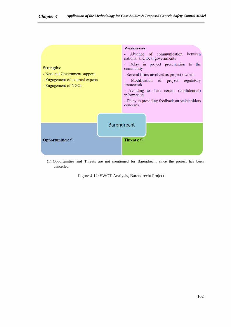
Chapter 4 Application of the Methodology for Case Studies & Proposed Generic Safety Control Model
162
(1) Opportunities and Threats are not mentioned for Barendrecht since the project has been
cancelled.
Figure 4.12: SWOT Analysis, Barendrecht Project
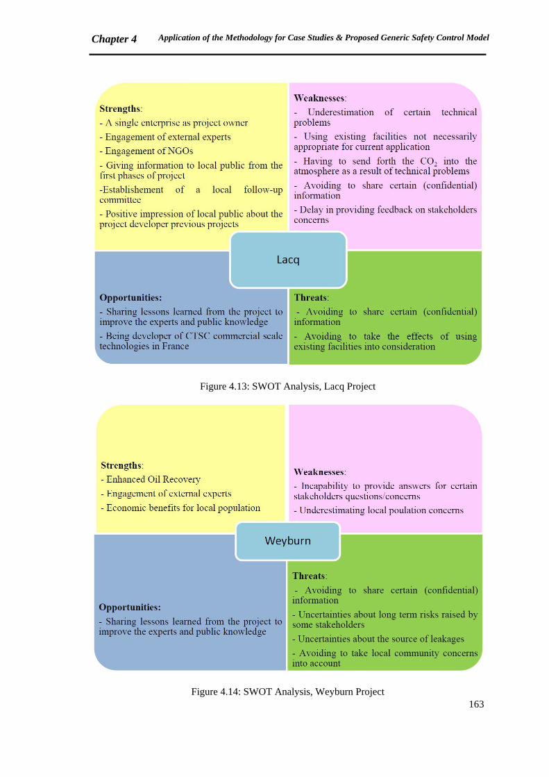
Chapter 4 Application of the Methodology for Case Studies & Proposed Generic Safety Control Model
163
Figure 4.13: SWOT Analysis, Lacq Project
Figure 4.14: SWOT Analysis, Weyburn Project
Chapter 4 Application of the Methodology for Case Studies & Proposed Generic Safety Control Model
164
Twelve factors have been recently proposed by IRGC, having the capacity to create an
appropriate context for emerging risks (already introduced in section 2.3.4).
“Conflicts about interests, values and science” is one of these factors. Authors of IRGC
report state that emerging risks may be intensified when opposition occurs on the
grounds of contested science or incompatible values. They argue that people have
subjective views about the science according to their own values. Hence, in case of
conflicts, interests and values of involved stakeholders should be clarified. Examples
are presented for both successful and failed attempts to block a technology or industrial
facility. The positive one is the conflicts on potential risks of LNG terminals, which are
managed successfully in the Netherlands through creative use of public participation
and local discussion. In the contrary, the US nuclear waste management is termed as a
failed example.
“Social dynamics” is another critical factor. Societies are continually evolving. As
complex systems, they may adapt to new or changing technologies … However, they
sometimes fail to adapt. It is reasoned that social dynamics are not directly controllable
but may be influenced in order to mitigate emerging risks. [IRGC, 2010]
Internal and external communication can also affect emerging risks intensification;
internal communication between the actors involved in risk management, and external
communication of these actors with the public. IRGC report underlines varied concerns
of people and scientists/regulators concerning CO2 Capture and Storage. Some people
are worried about safety risks and ground water contamination while others are more
concerned about the cost, the effect on their electric rates and property values [IRGC,
2010]. Communication allows improving risk management process by integrating all
stakeholder concerns.
When some stakeholders have got certain information about risks that is not available to
others, “information asymmetries” occur. In some cases, such as the ones related to
national security, information asymmetries are unavoidable. However, unavailability of
information for risk managers could lead to the negligence of prevention or protection
barriers in risk management process. Therefore, the identification and evaluation of
information asymmetries is important in the governance of emerging risks.
Communication is known as a key factor that could affect all other factors. [IRGC,
2010]
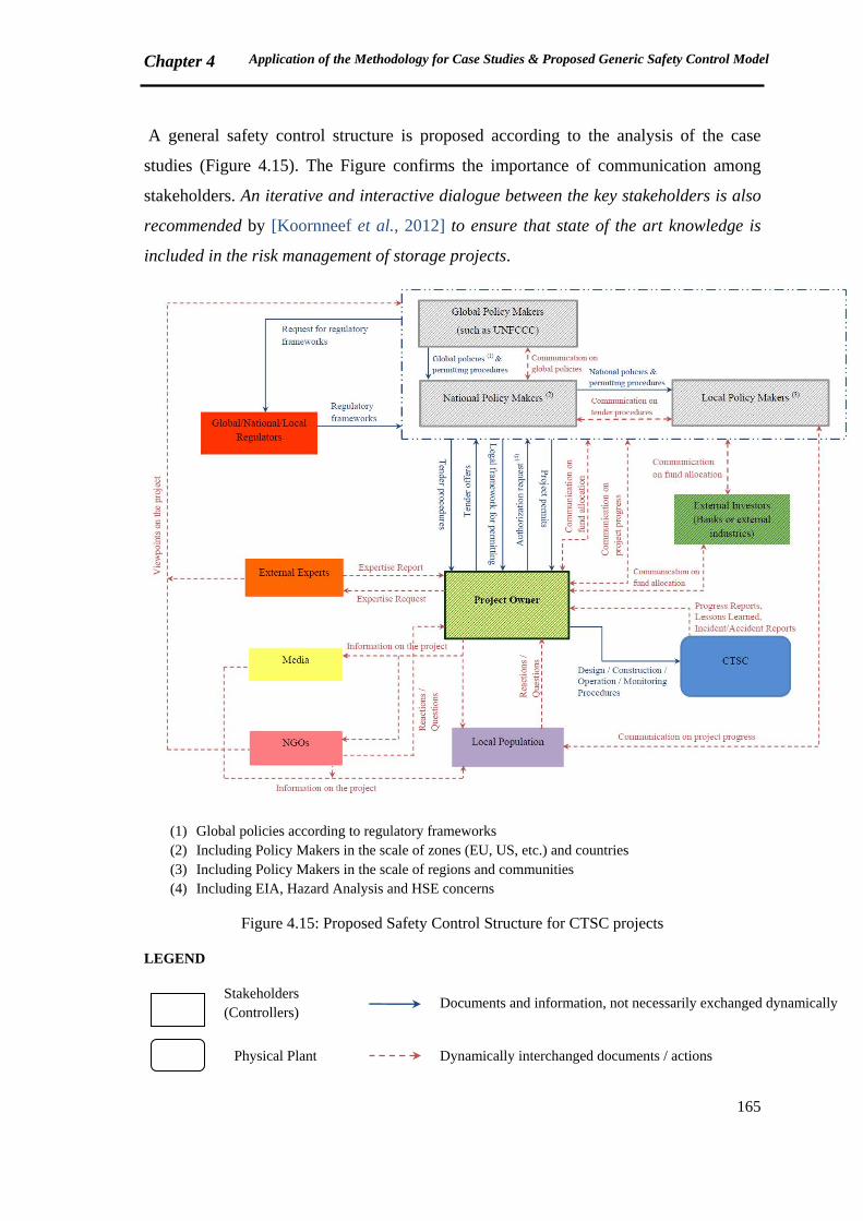
Chapter 4 Application of the Methodology for Case Studies & Proposed Generic Safety Control Model
165
A general safety control structure is proposed according to the analysis of the case
studies (Figure 4.15). The Figure confirms the importance of communication among
stakeholders. An iterative and interactive dialogue between the key stakeholders is also
recommended by [Koornneef et al., 2012] to ensure that state of the art knowledge is
included in the risk management of storage projects.
(1) Global policies according to regulatory frameworks (2) Including Policy Makers in the scale of zones (EU, US, etc.) and countries (3) Including Policy Makers in the scale of regions and communities (4) Including EIA, Hazard Analysis and HSE concerns
Figure 4.15: Proposed Safety Control Structure for CTSC projects
LEGEND
Stakeholders (Controllers)
Documents and information, not necessarily exchanged dynamically
Physical Plant
Dynamically interchanged documents / actions
Chapter 4 Application of the Methodology for Case Studies & Proposed Generic Safety Control Model
166
Potential Investors
In Figure 4.15, solid lines represent documents and information exchanged between the
stakeholders, not necessarily in a dynamic manner. Dash lines show the flow of
dynamic interchange, i.e. what should be maintained throughout the project life.
Global, National and Local Governments are regrouped in a box, since the relationship
of other stakeholders with the governments is varied in different regions.
Regulators are asked by Policy Makers for regulatory frameworks. Global policies and
permitting procedures are defined (by Global Policy Makers) for CTSC according to
regulatory frameworks and climate change policies. National policies and permitting
procedures are transposed to national contexts by National Policy Makers, who shall be
continuously in communication with Global and Local Policy Makers.
Tender procedures are sent to the Project Owner by the government. The Project Owner
returns the tender offers and if the offer is accepted, project permits will be provided in
reply to the authorization request of the Project Owner.
The hatched squares (including Governments, Project Owner and External Investors)
represent potential investors of the project who should intercommunicate on the funds
allocated for the project. There are still several uncertainties about the actors who have
to pay for developing CTSC technologies.
External Experts are always engaged to provide expertise usually on technical aspects
of the project.
Information on the project has to be shared dynamically with all stakeholders including
Local Population, NGOs and Media.
Communication is also essential between governments, NGOs and Local Population,
since local communities need to be assured of political support of their policy makers in
order to accept CTSC as a novel beneficial technology.
Delays, especially in communication, have to be minimized.
Figure 4.15 underlines the significance of information feedback loops within the safety
control structure of CTSC projects. As discussed previously in Chapter 2, information
feedbacks allow the actors to improve their mental models, decisions, strategies and
decision rules.
Chapter 4 Application of the Methodology for Case Studies & Proposed Generic Safety Control Model
167
Dulac asserts this opinion by remarking that improving mental models will consequently
improve the quality of safety-related decision-making … and the performance of
organizations and systems [Dulac, 2007]. As previously mentioned, risk acceptance and
risk communication are integrated in risk management process [Condor et al., 2011].
Risk communication involves providing information for stakeholders to improve their
understanding of the risks related to a phenomena or a technology. Mental models are
the schemas of human beings which help them make decisions. Investigating mental
models of both experts and lay people provide essential information for communication.
[Skarlatidou et al., 2012]
In the next chapter, principal features, advantages and limitations of the methodology
will be summarized and suggestions will be provided for further research.
Chapter 4 Application of the Methodology for Case Studies & Proposed Generic Safety Control Model
168
Summary, Chapter 4
In this chapter, application of the methodology for three case studies (Barendrecht, Lacq
and Weyburn) was explained. The case studies were selected based on the level of
project success. The context of each case study and major challenges related to each
project were presented. Safety control structures were developed for each example in
order to analyze the factors involved in the success or failure of projects.
Afterwards, the three projects were compared in terms of context and associated risks.
Reviewing the context in which these projects were/are working is important since
CTSC projects safety control structure is context specific. Furthermore, risks are
considered as emergent properties of systems in our approach, which need to be
analyzed in their particular context. Project scale, main objective and concerning
industry were mentioned as critical parameters that make the projects similar or
different. A section was devoted to studying the risks concerning the case studies.
Interconnections of the risks were presented in the form of causal graphs. Major
(potential) inadequate control actions having the potential to end or ended in delay or
failure of projects were discussed. The results were then illustrated in SWOT
(Strengths, Weaknesses, Opportunities and Threats) matrices. At the end of the chapter,
a generic safety control structure was proposed for CTSC projects, according to the
lessons learned from case studies analysis. Emphasis is placed on the importance of
information feedback loops and communication between stakeholders, which lead to
improve their mental models and decisions.
Chapter 4 Application of the Methodology for Case Studies & Proposed Generic Safety Control Model
169
Résumé (French Summary of Chapter 4)
Ce chapitre présente l’application de la méthodologie sur trois études de cas :
Barendrecht (Pay-Bas), Lacq (France) et Weyburn (US). Les études de cas ont été
sélectionnées selon le niveau de réussite des projets de CTSC. Le contexte de chaque
étude de cas et les défis majeurs liés à chaque projet ont été présentés. Les structures de
contrôle de sécurité ont été développées pour chaque exemple, afin d'analyser les
facteurs impliqués dans le succès ou l'échec des projets.
Ensuite, les trois projets ont été comparés selon leur contexte et les risques associés.
Examiner le contexte dans lequel ces projets ont été préparés et développés est
important puisque la structure de contrôle de sécurité des projets de CTSC est
spécifique au contexte. Par ailleurs, comme les risques sont considérés en tant que
propriétés émergentes des systèmes, il convient de les analyser selon leur propre
contexte. L’échelle du projet, son objectif principal et l'industrie concernée ont été
mentionnés en tant que paramètres critiques pour les comparer. Une partie de ce
chapitre a aussi été consacrée à l'étude des risques concernant ces études de cas. Les
interconnexions des risques ont été présentées sous forme des graphes causaux. Les
principales actions de contrôle inadéquates ayant entraînées ou ayant le potentiel
d’entraîner le retard ou l’échec des projets ont été examinées. Les résultats sont ensuite
illustrés sous forme des matrices SWOT (Strengths, Weaknesses, Opportunities and
Threats). À la fin du chapitre, une structure générique de contrôle de sécurité a été
proposée pour les projets de CTSC, selon les retours d’expérience issus de l’analyse des
études de cas. L'accent est mis sur l'importance des boucles de rétroaction d'information
et de la communication entre les parties prenantes, qui conduisent à améliorer leurs
modèles mentaux et leurs décisions en phase amont des projets de CTSC.

170
[Page intentionally left blank]

171
Chapter 5: Conclusions, Advantages & Limits of the Methodology and Suggestions for Further Studies
Chapter 5 Conclusions, Advantages & Limits of the Methodology and Suggestions for Further Studies
172
5.1 Proposed Methodology: Overview & Advantages
Capture, Transport and Storage of CO2 (CTSC) is considered as an essential technology
for climate change mitigation. However, risks and uncertainties related to long term
reliability of the technology have resulted in a kind of uncertain future for CTSC
projects development.
CTSC is claimed to play a new moderating role in opposition to coal [Stephens, 2012].
Such moderating role is extremely important in the current coal-dependent energy
policy. On the other hand, CTSC has been sometimes expressed as a technology that
leads to fossil-fuel lock-in [Unruh & Carrillo-Hermosilla, 2006; Vergragt et al., 2011]. It
is argued that CTSC will not help getting rid of fossil fuels. On the contrary, it could
amplify the dependence of energy market on fossil fuels. Stephens believes that CTSC
deals with a two-fold lock-in: technical and political. She argues that for those
governments and private companies that have already invested millions or billions of
dollars to advance CCS, ending their support for this technology may be difficult even if
perceptions of the relative challenges and potential of CCS continues to change over
time [Stephens, 2012].
Koornneef et al. have recently identified several knowledge gaps in the field of CTSC
environmental and risk assessment, which may have the potential to postpone the
implementation of CCS. They believe that uncertainties regarding risk assessment could
be a bottleneck for wide scale implementation of CCS if not properly addressed. In
terms of technical risk assessment, Capture and Transport are supposed to be
sufficiently understood, although further studies are required to identify potential failure
scenarios and their consequences. CO2 storage is known as a non-engineered part of the
chain for which quantitative risk assessment is currently impossible [Koornneef et al.,
2012]. EU commission has confirmed that uncertainty is a major barrier to invest on
low carbon energy systems [EU commission, 2011].
A systemic risk management framework for CTSC projects has been proposed in this
work. The approach is founded on the concepts of systems thinking, STAMP, STPA
and system dynamics. The objective is to provide a means of decision making for CTSC
projects development in the actual context where the future of the technology is
uncertain. Risk management is considered as a means of control that should be able to
Chapter 5 Conclusions, Advantages & Limits of the Methodology and Suggestions for Further Studies
173
propose a control structure for the whole system. Stakeholders are viewed as controllers
of the system. Four conditions are required for the controller [Leveson, 2009]:
- Having a goal
- Being able to affect the system
- Being or contain a model of the system
- Being able to observe the system
Eight Large Scale Integrated CTSC projects have been cancelled in 2011 and 2012 for
different reasons especially insufficient or uncertain financial resources, lack of political
support and regulatory issues. Projects were cancelled in different countries such as UK,
Germany, US, Canada and Australia, and at various stages of development [GCCSI,
2012b]. In 2009, global financial crisis had been identified as a key reason of CTSC
projects cancelling or delay [GCCSI, 2009b].
In the previous chapters, actual context of CTSC, theoretical basis of the approach and
details of methodology application have been discussed.
Major risks involved in CTSC projects progress have been categorized in eight groups
including Technical, HSE (Health, Safety and Environment), Policy/Strategy, Legal,
Organizational/Human, Financial/Economic, Social and risks concerning the Project.
Thirty nine risks have been identified according to literature review, available projects
information and discussions with experts. The risks have been classified for Capture,
Transport and Storage subsystems and for different phases of the project. Opportunity,
Definition and planning, Engineering, Construction, Operation (Injection of CO2) and
Post-injection (Monitoring) are the main project phases that have been taken into
account. In order to analyze the risks preventing project progress, the ones related to the
phases prior to engineering have been selected and modeled by the proposed
methodology. The aim was to study the feedback networks affecting the risks
amplification. The analysis has been started from stock / flow models of each risk.
Models have been subsequently grouped together in order to study interconnections of
risks and feedback loops result in project failure or success.
Safety control structures of three case studies have been reviewed to find a generic
structure that could work for CTSC projects. Inadequate control actions to maintain
safety constraints have been discussed. The idea comes from STAMP and STPA
approaches, developed at MIT. The proposed safety control structure has been presented

Chapter 5 Conclusions, Advantages & Limits of the Methodology and Suggestions for Further Studies
174
in chapter 4, following comparison of the case studies in terms of context and associated
risks. The purpose was to underline the significance of endogenous point of view in
analyzing the risks of CTSC projects. It has been argued that feedbacks and feedback
loops have to be understood and studied in the networks of risks and stakeholders.
Emphasis is placed on the importance of providing endogenous explanations for CTSC
actual development context. As discussed earlier in chapter 2, it is more favorable to
have endogenous perceptions about all phenomena.
CTSC risk management is context specific and depends on several factors such as
national and local circumstances. In spite of that, seeking for individual benefits is
indeed a major concern of all stakeholders. Oil and gas industry is currently more
involved in the field by investing on CTSC EOR projects. Oil recovery increase is the
main obvious advantage of EOR systems.
Lessons learned from the modeling process of this work show that dynamic information
sharing and communication are essential to support the contribution of CTSC
technologies in climate change mitigation.
The thesis contribution provides a decision making support for the progress of CTSC
projects. Systemic modeling of CTSC project risks can help the stakeholders to share
and improve their mental models and accordingly, their strategies and decisions.
In order to give a summary of the proposed methodology advantages, we have to go
back to available CTSC risk management approaches. As discussed in chapter 1, several
works have been already performed on risk management of CTSC. Most of these works
are focused on one part of the chain, i.e. Capture, Transport or Storage; and especially
on technical aspects of risk. However, in chapter 1 we introduced some integrated
approaches of CTSC risk management. INERIS, National Institute of Industrial
Environment and Risks in France, proposes a global risk analysis approach for CTSC
chain. They propose to integrate the notion of time to the classic concepts of probability
and severity for CTSC risk analysis. Three time scales are suggested: operation (max.
50 years), monitoring (max. 150-200 years) and long term (up to 1000 years). Different
aspects of risks are not included in the approach of INERIS. Their study is focused on
technical risk scenarios related to storage [Farret et al., 2009]. Therefore, in subsequent
paragraphs we will review the main characteristics of two available integrated
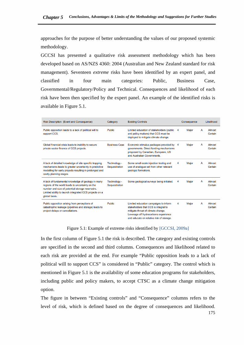
Chapter 5 Conclusions, Advantages & Limits of the Methodology and Suggestions for Further Studies
175
approaches for the purpose of better understanding the values of our proposed systemic
methodology.
GCCSI has presented a qualitative risk assessment methodology which has been
developed based on AS/NZS 4360: 2004 (Australian and New Zealand standard for risk
management). Seventeen extreme risks have been identified by an expert panel, and
classified in four main categories: Public, Business Case,
Governmental/Regulatory/Policy and Technical. Consequences and likelihood of each
risk have been then specified by the expert panel. An example of the identified risks is
available in Figure 5.1.
Figure 5.1: Example of extreme risks identified by [GCCSI, 2009a]
In the first column of Figure 5.1 the risk is described. The category and existing controls
are specified in the second and third columns. Consequences and likelihood related to
each risk are provided at the end. For example “Public opposition leads to a lack of
political will to support CCS” is considered in “Public” category. The control which is
mentioned in Figure 5.1 is the availability of some education programs for stakeholders,
including public and policy makers, to accept CTSC as a climate change mitigation
option.
The figure in between “Existing controls” and “Consequence” columns refers to the
level of risk, which is defined based on the degree of consequences and likelihood.
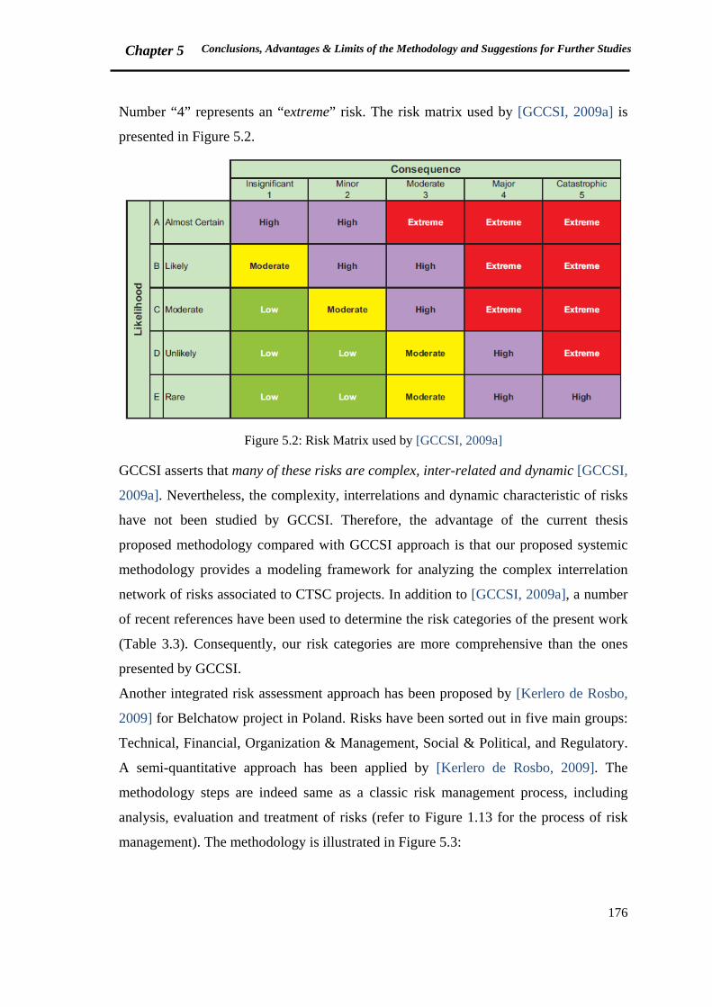
Chapter 5 Conclusions, Advantages & Limits of the Methodology and Suggestions for Further Studies
176
Number “4” represents an “extreme” risk. The risk matrix used by [GCCSI, 2009a] is
presented in Figure 5.2.
Figure 5.2: Risk Matrix used by [GCCSI, 2009a]
GCCSI asserts that many of these risks are complex, inter-related and dynamic [GCCSI,
2009a]. Nevertheless, the complexity, interrelations and dynamic characteristic of risks
have not been studied by GCCSI. Therefore, the advantage of the current thesis
proposed methodology compared with GCCSI approach is that our proposed systemic
methodology provides a modeling framework for analyzing the complex interrelation
network of risks associated to CTSC projects. In addition to [GCCSI, 2009a], a number
of recent references have been used to determine the risk categories of the present work
(Table 3.3). Consequently, our risk categories are more comprehensive than the ones
presented by GCCSI.
Another integrated risk assessment approach has been proposed by [Kerlero de Rosbo,
2009] for Belchatow project in Poland. Risks have been sorted out in five main groups:
Technical, Financial, Organization & Management, Social & Political, and Regulatory.
A semi-quantitative approach has been applied by [Kerlero de Rosbo, 2009]. The
methodology steps are indeed same as a classic risk management process, including
analysis, evaluation and treatment of risks (refer to Figure 1.13 for the process of risk
management). The methodology is illustrated in Figure 5.3:
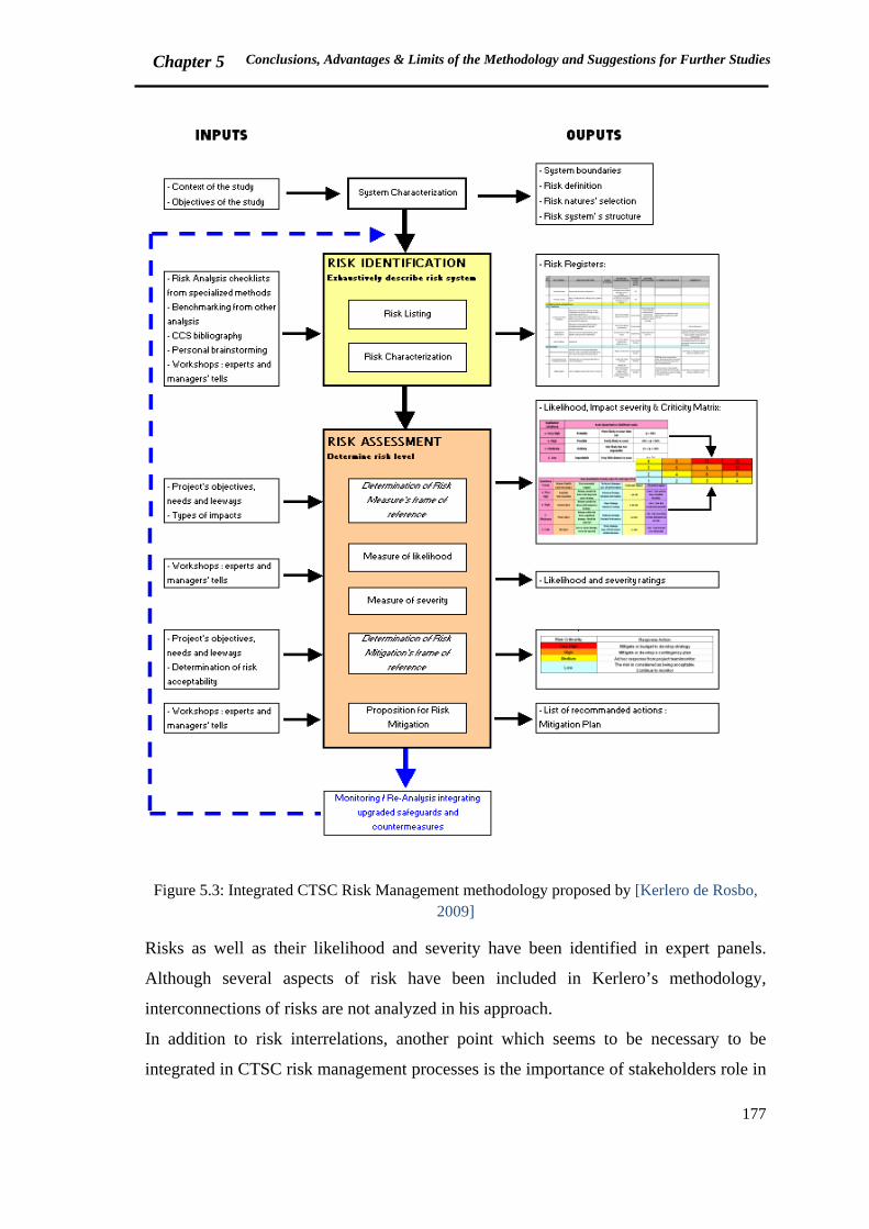
Chapter 5 Conclusions, Advantages & Limits of the Methodology and Suggestions for Further Studies
177
Figure 5.3: Integrated CTSC Risk Management methodology proposed by [Kerlero de Rosbo, 2009]
Risks as well as their likelihood and severity have been identified in expert panels.
Although several aspects of risk have been included in Kerlero’s methodology,
interconnections of risks are not analyzed in his approach.
In addition to risk interrelations, another point which seems to be necessary to be
integrated in CTSC risk management processes is the importance of stakeholders role in
Chapter 5 Conclusions, Advantages & Limits of the Methodology and Suggestions for Further Studies
178
the project success or failure. The significance of safety control structure (as defined in
chapter 3) has not been taken into account in the integrated methods of [GCCSI, 2009a]
and [Kerlero de Rosbo, 2009]. Responsibilities of different stakeholders of CTSC
project is what we have highlighted in our systemic approach. Each stakeholder is
considered as a controller who has to maintain specific safety constraints in order to
fulfill the objective of safety structure, i.e. preventing delay or failure of CTSC project.
In the current thesis, defects of safety control structure have been noted as major
potential cause of a CTSC project failure (refer to Barendrecht project analysis, section
4.1.1).
To sum up, three advantages can be listed for the systemic methodology which is
proposed in this thesis:
- Presenting more comprehensive list and categories of risks related to CTSC chain
- Taking into account the complex network of risk interconnections by proposing a
systemic modeling framework
- Underlining the significance of stakeholders role in the project success or failure, by
proposing a modeling approach for safety control structure of projects and analyzing
required and (potential) inadequate control actions of stakeholders in relation to each
risk
The systemic methodology proposed in this thesis has some limitations in spite of its
advantages and added values. Limitations are classified in three groups presented
hereafter.
5.2 (Potential) Limitations of the proposed methodology
5.2.1 Lack of information on CTSC
Refer to the discussions of chapter 3, CTSC integrated chain is an emerging technology
for which there is not a great amount of publicly available information [CCP, 2007].
Details of case studies are usually unavailable due to confidentiality issues.
Nevertheless, the methodology has been applied for three case studies on the basis of
accessible data in the literature, project reports and discussions with experts. The
analysis could be improved based upon lessons learned from further development of
projects.

Chapter 5 Conclusions, Advantages & Limits of the Methodology and Suggestions for Further Studies
179
5.2.2 Qualitative vs. quantitative approach
A qualitative approach was proposed in this thesis for risk management of CTSC. It
may be debated that quantitative methods are more practical or more comprehensible. In
this section, the notion of quantification is reviewed from three points of view: risk
quantification, quantification in STAMP approach, and system dynamics quantitative
modeling.
As mentioned earlier in chapter 1, operators and public organizations have initially
tried to quantify damages and consequences of potential accidents, before to
understand why and how they could occur [Tixier et al., 2002]. From another
standpoint, quantitative approaches are not necessarily the most adapted ones for
modern complex sociotechnical systems [Dulac, 2007, p.29]. Altenbach mentions ten
reasons for which risks should not be quantified. Controversiality, potential use of
numbers out of context, simplification of numbers for challenge and criticism, being
time consuming and costly, uncertainties, requirement of more training, data
requirement, being threatening and compelling, usefulness of qualitative results and
difficulty to communicate the concept of probability are noted as the reasons not to
quantify risks [Altenbach, 1995].
The proposed methodology is based on STAMP approach, which has been mostly used
as a qualitative tool to analyze accidents or risks. Dulac affirms that quantitative values
generated in the simulations are sometimes of secondary importance in comparison to
the qualitative learning opportunities presented by the model and the modeling process
[Dulac, 2007, p.213]. The significance of modeling process is also attested by [Durand,
2010].
From system dynamics point of view, qualitative or “soft” applications of stock-flow
and / or causal diagrams are recognized as useful as simulation applications. Qualitative
use allows developing feedback networks and understanding the system behavior
[Winch, 2000].
Hence, being qualitative is not a limitation of the proposed methodology. As Coyle
suggests, we should wonder how much value does quantified modeling in system
dynamics add to qualitative analysis [Coyle, 2000].
Chapter 5 Conclusions, Advantages & Limits of the Methodology and Suggestions for Further Studies
180
5.2.3 Subjectivity of modeling and risk assessment
Modeling, which is a simplification of reality, is made by an individual or a group of
individuals. As a result, modeling is always a subjective process, depending on the
reasoning of modeler(s). The models developed in this thesis are not an exception. They
have been created based on the mental models of the modeler, which are inevitably
restricted. According to Durand, modeling is an art and not an established technique
[Durand, 2010, p.68]. Models of the current thesis are made by only one modeler and
have not been verified by an expert panel. Group modeling provides different points of
view to improve the models.
In addition, risk assessment is a subjective process since expert judgment is an
indispensable characteristic of risk assessment process.
5.3 Suggestions for further studies
CTSC risk management deals with several gaps and issues, and therefore requires more
research. Further studies could be carried out on the subjects already introduced as
limitations of the methodology.
Development of CTSC projects will provide lessons learned for improving the models.
New information could be used to put figures on the variables of models in group
modeling panels. Figures help to make semi-quantitative analyses which may be more
understandable for some stakeholders. Effects of feedback loop networks on the
probability and intensity of risks could be studied in semi-quantitative approaches.
Financial/Economic aspects have to be developed in detail in further studies.
Significance of CO2 monetary systems such as EU ETS (European Union Emissions
Trading System) needs to be analyzed thoroughly.
Models and control structures of chapters 3 and 4 provide an appropriate basis for
stakeholder discussion panels. Different failure scenarios in the developed feedback
network models could be envisaged and studied in the discussion panels. Cumulative
effects of failures are recommended to be studied by thinking about cumulative
consequences of risks, as stock variables of the models. Modeling could be a learning
and communication tool for operators, managers and all the actors engaged in the
prevention and management of risk [Garbolino et al., 2010]. Copin confirms that
Chapter 5 Conclusions, Advantages & Limits of the Methodology and Suggestions for Further Studies
181
dynamic modeling could be a tool for training the actors in the organization, particularly
managers. Application of software, such as STELLA® or VENSIM®, makes it easier to
train the actors and help them to make required decisions [Copin, 2000].
The proposed modeling framework could be served to study the performance of CTSC
within a comprehensive framework. Current main aspects of CTSC performance
include:
- Economic performance:
Economic performance is an essential aspect of CTSC performance. As noted in
previous chapters, high cost of capture processes is a major concern. Capital cost of
the plant with and without CO2 capture and cost of electricity production with and
without CO2 capture are some of the critical economic performance indicators
[Rubin et al., 2007].
- Technical performance:
Technical performance of CTSC technologies has various facets including energetic
and environmental.
As discussed earlier and at the beginning of the current chapter, CTSC is still
principally dependent on fossil fuels while it is supposed to be a technological option
to reduce fossil fuel-based CO2 emissions. Hence, further studies are required on
energetic performance of CTSC.
CTSC environmental performance has to be analyzed according to CO2 emission
factors with and without capture process.
Details of technical performance indicators are not in the scope of this thesis. More
information is available in several references such as [Koornneef et al., 2012; Rubin
et al., 2007].
- Organizational performance:
As previously argued, CTSC is a complex sociotechnical system in which several
public and private organizations are engaged as stakeholders. Managing risks and
uncertainties needs an interactive communication of stakeholders. Organizational
performance plays a significant role in sustainability of CTSC projects
implementation.
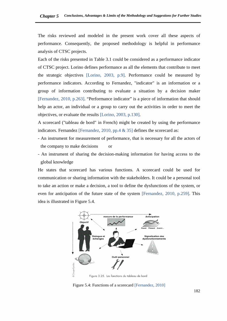
Chapter 5 Conclusions, Advantages & Limits of the Methodology and Suggestions for Further Studies
182
The risks reviewed and modeled in the present work cover all these aspects of
performance. Consequently, the proposed methodology is helpful in performance
analysis of CTSC projects.
Each of the risks presented in Table 3.1 could be considered as a performance indicator
of CTSC project. Lorino defines performance as all the elements that contribute to meet
the strategic objectives [Lorino, 2003, p.9]. Performance could be measured by
performance indicators. According to Fernandez, "indicator" is an information or a
group of information contributing to evaluate a situation by a decision maker
[Fernandez, 2010, p.263]. “Performance indicator” is a piece of information that should
help an actor, an individual or a group to carry out the activities in order to meet the
objectives, or evaluate the results [Lorino, 2003, p.130].
A scorecard ("tableau de bord" in French) might be created by using the performance
indicators. Fernandez [Fernandez, 2010, pp.4 & 35] defines the scorecard as:
- An instrument for measurement of performance, that is necessary for all the actors of
the company to make decisions or
- An instrument of sharing the decision-making information for having access to the
global knowledge
He states that scorecard has various functions. A scorecard could be used for
communication or sharing information with the stakeholders. It could be a personal tool
to take an action or make a decision, a tool to define the dysfunctions of the system, or
even for anticipation of the future state of the system [Fernandez, 2010, p.259]. This
idea is illustrated in Figure 5.4.
Figure 5.4: Functions of a scorecard [Fernandez, 2010]
Chapter 5 Conclusions, Advantages & Limits of the Methodology and Suggestions for Further Studies
183
The works of Kaplan and Norton might be helpful in terms of performance from
company manager’s point of view. They believe that executives want a balanced
presentation of measures that allow them to view the company from several
perspectives simultaneously. They have developed a new performance measurement
system, called "balanced scorecard", to give top managers a comprehensive view of the
business. The balanced scorecard covers not only financial measures but also three
groups of operational measures including customer satisfaction, internal processes, and
the organization's ability to learn and improve [Kaplan & Norton, 1992]. Each of the
risk categories previously presented for CTSC (Table 3.3) could be included in the first
or third operational measures of Kaplan and Norton (customer satisfaction or the
organization's ability to learn and improve). Technical, Project, HSE and
Organizational/Human risks are the most relevant issues that could be considered in
internal processes category of Kaplan and Norton measures.
The risks that have been presented in the current work could provide information for
creating a scorecard of control and monitoring CTSC project performance. As
previously discussed, one of the concerns is that most of the risks presented in Table 3.1
are complex issues which are still under study. Hence, acquiring information to quantify
performance indicators will be a challenge, which needs the contribution of experts
from different fields while CTSC projects are developing.
Another issue that needs to be improved is the concept of delay, already introduced and
reviewed in this work. Additional study on potential decision making delays and their
consequences on the project progress will be valuable.
The methodology and developed models could not be verified due to lack of time.
Further work is recommended to evaluate and enhance the models, with the assistance
of stakeholders, especially project owners. Participation of a group of CTSC and system
dynamics experts will be useful in the evaluation process. The methodology is
suggested to be applied for a CTSC project in feasibility study or definition phase.
Chapter 5 Conclusions, Advantages & Limits of the Methodology and Suggestions for Further Studies
184
Summary, Chapter 5
In chapter 5, the most significant points of the context and the proposed methodology
were wrapped up. It was discussed that CTSC deals with two kind of lock-ins: technical
and political. Technical lock-in involves the notion of fossil fuel lock-in, and the fact
that CTSC technologies extremely depend upon fossil fuel consumption. This situation
is claimed as being contrary to CTSC contribution in climate change mitigation. Such
ambiguous position along with uncertainties concerning risk assessment could be a
barrier for investing on large scale CTSC projects.
The methodology which is proposed in the current thesis provides a means of decision
making for CTSC projects development. The methodology was compared with two
available integrated CTSC risk management approaches. The major advantages include:
more comprehensive list and categories of risks, taking into account the complex
network of risk interconnections, and highlighting the significance of stakeholders role
in the project success or failure.
(Potential) Limitations of the methodology were presented in section 2. Lack of
information on CTSC, debate on the requirement of quantitative or qualitative risk
management approaches, and subjectivity of modeling and risk assessment are the most
important limitations of the current work. Some suggestions for future research were
provided at the final section. It was argued that the proposed methodology can be useful
in studying the general performance of CTSC from economic, technical and
organizational points of view. In addition, the presented risks could be considered as
performance indicators of CTSC projects, which could provide information for creating
a scorecard.
Chapter 5 Conclusions, Advantages & Limits of the Methodology and Suggestions for Further Studies
185
Résumé (French Summary of Chapter 5)
Le chapitre 5 résume les points les plus importants du contexte et de la méthodologie
proposée. La technologie de CTSC est enferrée dans un double contexte technique et
politique. Le blocage technique implique la dépendance du CTSC face à la
consommation de combustibles fossiles. Cette situation est considérée comme contraire
à la contribution du CTSC pour atténuer le changement climatique. Avec une telle
position ambiguë ainsi que des incertitudes concernant l'évaluation des risques, les
projets de CTSC à grande échelle rencontrent des difficultés pour leur développement.
La méthodologie qui est proposée dans cette thèse fournit un moyen de prise de
décision pour développement des projets de CTSC. La méthodologie a été comparée
avec deux approches intégrées qui sont disponibles pour le management des risques du
CTSC. Les avantages majeurs comprennent : une liste et des catégories plus complètes
des risques, la pris en compte de réseau complexe des interconnexions entre les
différents risques, et la mise en évidence de l’importance du rôle des parties prenantes
pour le succès ou l’échec du projet. Nous avons donc proposé que notre méthodologie
puisse être utile à l’étude de la performance générale du CTSC du point de vue
économique, technique et organisationnel.
Les Limites potentielles de la méthodologie ont été présentées dans la deuxième partie
du chapitre. Le manque d'informations sur le CSTC, le débat sur l'exigence des
approches quantitatives ou qualitatives de gestion des risques, et la subjectivité de la
modélisation et de l'évaluation des risques constituent les principales limites de ce
travail. Quelques suggestions ont été fournies dans la partie finale pour les perspectives
de recherches. Parmi elles, le recours à l’intégration d’indicateurs de performance en
risk management dans des tableaux de bord constituerait un moyen dédié aux parties
prenantes pour accompagner le développement et le suivi des projets de CTSC.
186
References
A
Altenbach, T.J. (1995), A Comparison of Risk Assessment Techniques from Qualitative to Quantitative, submitted to the ASME Pressure and Piping Conference, Honolulu, Hawaii, July 23-27, 1995
Arslan, O., Deha Er, I. (2008), SWOT analysis for safer carriage of bulk liquid chemicals in tankers, Journal of Hazardous Materials 154 (2008) 901–913, doi:10.1016/j.jhazmat.2007.10.113
Ashworth, P., Bradbury, J., Feenstra C.F.J., Greenberg, S., Hund, G., Mikunda, T., Wade, S. (2010), Communication, project planning and management for carbon capture and storage projects: An international comparison, CSIRO, Australia
B
BARPI (2012), Barpi: vingt ans d’accidents industriels, Bureau d’Analyse des Risques et Pollutions Industriels, Face au risque, n° 481, mars 2012, Accessed September 23, 2012 http://www.aria.developpement-durable.gouv.fr/ressources/em4_barpi_20_ans.pdf
Benson, S.M. (2002), Comparative Evaluation of Risk Assessment, Management and Mitigation Approaches for deep geological storage of CO2, Earth Sciences Division, E.O. Lawrence Berkeley National Laboratory
Benson, S.M. (2007), Overview of Geological Storage of CO2, Presentation in geological storage roundtable, Washington DC, May 31, 2007
Bertrane, M. (2011), L'évaluation des risques majeurs dans les projets de captage et transport de CO2, Presentation of Centre Technique Industrie, Bureau Veritas, Presented in the international seminar on Capture, Transport and Storage of CO2, Risk Management: Methods, Practical Experiences and Perspectives, April 7-8, 2011, Le Havre, France
Bouc, O., Audigane, P., Bellenfant, G., Fabriol, H., Gastine, M., Rohmer, J., Seyedi, D. (2009), Determining safety criteria for CO2 geological storage, Energy Procedia (1) 2439-2446
BRGM (2005), Stockage Géologique du CO2: analyses des risqué, surveillance et mesures. Rapport Final, septembre 2005
C
Cambon, J. (2007), Vers une nouvelle méthodologie de mesure de la performance des systèmes de management de la sante-sécurité au travail, Thèse pour obtenir le grade de docteur de l’Ecole des Mines de Paris, Spécialité : Sciences et Génie des Activités à Risques, novembre 2007
187
Carayon, P. (2006), Human factors of complex sociotechnical systems, Applied Ergonomics 37 (2006): 525-535, doi: 10.1016/j.apergo.2006.04.011
CBC news (2011), CO2 leaks worry Sask. Farmers, last updated: Tuesday, January 11, 2011, 8:49 PM, Accessed September 10, 2012, http://www.cbc.ca/news/business/story/2011/01/11/sk-carbon-complaint-1101.html,
CCJ (2010), Shell Barendrecht project cancelled, Carbon Capture Journal, November 5, 2010, Accessed June 22, 2012 http://www.carboncapturejournal.com/displaynews.php?NewsID=676 CCP (2007), Public Perception of Carbon Dioxide Capture and Storage: Prioritized Assessment of Issues and Concerns, Summary for Policy-Makers, CO2 Capture Project®, March 2007, Accessed July 20, 2012 http://ccs101.ca/assets/Documents/iea_public_perception_of_ccs.pdf
CCP (2010), Update on selected regulatory issues for CO2 Capture and Geological Storage, CO2 Capture Project®, Final Report, November 2010
CCP (2012), CCS stakeholder issues, Review and Analysis, CO2 Capture Project®, Final Report, February 2012
CCS101 (2009) a, Interview with Debra Button, Mayor of Weyburn, October 2009, The carbon capture and storage information source, Accessed September 26, 2012, http://ccs101.ca/ccs_communities
CCS101 (2009) b, Interview with Carmen Sterling, Reeve of the Rural Municipality of Weyburn, October 2009, The carbon capture and storage information source, Accessed September 26, 2012, http://ccs101.ca/ccs_communities
Chammas, R., Poupard, O. (2011), Risk Management in CCS Projects, Risk management framework in CCS projects –a key challenge for a sustainable project, Presentation of OXAND, Presented in the international seminar on Capture, Transport and Storage of CO2, Risk Management: Methods, Practical Experiences and Perspectives, April 7-8, 2011, Le Havre, France
CLIS (2008), CLIS (Commission Locale d’Information et de Suivi), Évaluation du projet de captage et stockage de CO2 à Rousse 1, Dossier présenté par Total, 29/09/2008, Accessed November 12, 2010 http://www.pyrenees-atlantiques.pref.gouv.fr/sections/actions_de_l_etat/environnement_et_dev/actualites/
CLIS (2011), CLIS (Commission Locale d’Information et de Suivi), Demande de prolongation de la phase d’injections, 12/09/2011, Accessed December 15, 2011 http://www.pyrenees-atlantiques.pref.gouv.fr/sections/actions_de_l_etat/environnement_et_dev/actualites/
188
Condor, J., Unatrakarn, D., Wilson, M., Asghari, K. (2011), A Comparative Analysis of Risk Assessment Methodologies for the Geologic Storage of Carbon Dioxide, Energy Procedia 4 (2011) 4036–4043, doi:10.1016/j.egypro.2011.02.345
Cooke, D.L., Rohdeler, T.R. (2006), Learning from incidents: from normal accidents to high reliability, System Dynamics Review, 22 (3) 213-239
Copin, S. (2000), Modélisation des processus qui sous-tendent la motivation d’un acteur au sein d’une organisation, Thèse, Université de Paris 1-Panthéon-Sorbonne, Octobre 2000
Coyle, G. (2000), Qualitative and quantitative modelling in system dynamics: some research questions, System Dynamics Review (16), No. 3: 225–244.
C&S Conseils (2008), Bilan de la concertation, Projet pilote de captage stockage de CO2 dans le bassin de Lacq, Janvier 2008, Accessed April 13, 2012 http://www.total.com/MEDIAS/MEDIAS_INFOS/2186/FR/
CTSC chair, http://www.chaire-ctsc.fr/home, Accessed October 26, 2012
D
De Coninck, H., Flach, T., Curnow, P., Richardson, P., Anderson, J., Shackley, S., Sigurthorsson, G., Reiner, D. (2009), The acceptability of CO2 capture and storage (CCS) in Europe: An assessment of the key determining factors, Part 1. Scientific, technical and economic dimensions, International journal of greenhouse gas control 3 (2009) 333–343, doi:10.1016/j.ijggc.2008.07.009
De Rosnay, J. (1975), Le macroscope, Paris, Le Seuill
Desroches, A., Leroy, A., Quaranta, J.F., Vallée, F. (2006), Dictionnaire d'analyse et de gestion des risques, Lavoisier, p.232
Desroches, A., Leroy, A., Vallée, F. (2007), La gestion des risques, Lavoisier, p.101
De Visser, E., Hendriks, Ch., Barrio, M., Mølnvik, M., De Koeijer, G., Liljemark, S., Le Gallo, Y. (2008), Dynamis CO2 quality recommendations, International Journal of greenhouse gas control 2 (2008) 478-484, doi:10.1016/j.ijggc.2008.04.006
DNV (2010), Design and operation of CO2 pipelines Recommended practice DNV-RP-J202, Det Norske Veritas, Norway, April 2010
Dulac, N. (2007), A framework of dynamic safety and risk management modeling in complex engineering systems, PhD thesis submitted to the department of aeronautical and astronautical engineering at MIT, February 2007
Dulac, N., Owens, B., Leveson, N., Barrett, B., Carroll, J., Cutcher-Gershenfeld, J., Friedenthal, S., Laracy, J., Sussman, J. (2007), Demonstration of a New Dynamic Approach to Risk Analysis for NASA’s Constellation Program, MIT CSRL Final Report to the NASA ESMD Associate Administrator, March 2007
189
Durand, D. (2010), La systémique, Presses Universitaires de France (PUF), 11th ed., January 2010
E
Ecojustice (2011), Ecojustice reply to PTRC response to soil gas studies, January 28, 2011, Accessed July 20, 2012, http://www.ipac-co2.com/uploads/File/PDFs/ecojustice%20response.pdf
Energy Institute (2010), Technical guidance on hazard analysis for onshore carbon installations and onshore pipelines, published by Energy Institute, London, 1st edition, September 2010
EPA (2000), Carbon Dioxide as a Fire Suppressant: Examining the Risks, United States Environmental Protection Agency, February 2000, Accessed June 19, 2012 http://www.epa.gov/Ozone/snap/fire/co2/co2report.pdf
EPA (2010), Human-Related Sources and Sinks of Carbon Dioxide, United States Environmental Protection Agency, Accessed August 2010 http://www.epa.gov/climatechange/emissions/co2_human.html#industrial
ESRL (2012), Earth System Research Laboratory, NOAA/ESRL, Accessed June 7, 2012 www.esrl.noaa.gov/gmd/ccgg/trends/global.html
EU commission (2011), Communication from the commission to the European parliament, the council, the European economic and social committee and the committee of the regions, Energy Roadmap 2050, European Commission, Accessed January 30, 2012 http://ec.europa.eu/energy/energy2020/roadmap/doc/com_2011_8852_en.pdf
EU Directive (2009), Directive 2009/31/EC of the European Parliament and of the Council of 23 April 2009, on the geological storage of carbon dioxide and amending Council Directive 85/337/EEC, European Parliament and Council Directives 2000/60/EC, 2001/80/EC, 2004/35/EC, 2006/12/EC, 2008/1/EC and Regulation (EC) No 1013/2006
Eurlex website, Official Journal of European Union, Official Journal L 010, 14/01/1997 P.0013 – 0033, Accessed June 12, 2012 http://eur-lex.europa.eu/LexUriServ/LexUriServ.do?uri=CELEX:31996L0082:EN:HTML
F
Fabriol, H. (2009), Risk management and uncertainties: ensuring CO2 storage safety, 3rd International Symposium: Capture and Geological Storage of CO2, 5-6 November 2009, Paris

190
Farret, R., Gombert, P., Lahaie, F., Roux, P. (2009), Vers une méthode d'analyse des risques globale de la filière CSC, intégrant plusieurs échelles de temps, Rapport Scientifique, INERIS, 2008-2009, pp 100-103
Feenstra, C.F.J., Mikunda, T., Brunsting S. (2010), What happened in Barendrecht?, Case study on the planned onshore carbon dioxide storage in Barendrecht, the Netherlands, ECN/CAESAR, November 3, 2010
Fernandez, A. (2010), Les nouveaux tableaux de bord des managers, 4e édition, EYROLLES, éditions d'Organisation
Forrester, J.W. (1968), Industrial Dynamics, The MIT press, 5th printing, May 1968
Forrester, J.W. (1991), System Dynamics and the Lessons of 35 years, Massachusetts Institute of Technology http://sysdyn.clexchange.org/people/jay-forrester.html
Forrester, J.W. (1996), The Beginning of System Dynamics, Massachusetts Institute of Technology http://sysdyn.clexchange.org/people/jay-forrester.html
Forrester, J.W. (2007), System dynamics-the next fifty years, System Dynamics Review, Vol.23, No. 2/3 (Summer/Fall 2007): 359-370, doi: 10.1002/sdr.381
Fuchs, H.U. (2006), System dynamics modeling in science and engineering, Invited talk at the system dynamics conference at the University of Puerto Rico, Resource center for science and engineering, Mayaguez, December 8-10, 2006
G
Gale, J., Davison, J. (2004), Transmission of CO2—safety and economic considerations, Energy 29 (2004) 1319–1328, doi:10.1016/j.energy.2004.03.090
Garbolino, E., Chéry, J.P., Guarnieri, F. (2009), Dynamic systems modelling to improve risk analysis in the context of Seveso industries, Chemical Engineering Transactions (17) 373-378
Garbolino, E., Chéry, J.P., Guarnieri, F. (2010), Modélisation dynamique des systèmes industriels à risques, Sciences du Risques et du Danger (SRD), Lavoisier
Garlick, A. (2007), Estimating Risk, A management approach, Gower Publishing Limited, England, pp 9-31
GCCSI (2009) a, Strategic Analysis of the Global Status of Carbon Capture and Storage, Report 5: Synthesis Report, Global CCS Institute, Canberra, Australia
GCCSI (2009) b, Strategic Analysis of the Global Status of Carbon Capture and Storage, Report 1: Status of Carbon Capture and Storage Projects Globally, Global CCS Institute 2009, Canberra, Australia

191
GCCSI (2011) a, The global status of CCS: 2011, Global CCS Institute 2011, Canberra, Australia, ISBN 978-0-9871863-0-0
GCCSI (2011) b, Accelerating the uptake of CCS: Industrial use of captured carbon dioxide, Global CCS Institute, March 2011
GCCSI (2012) a, Global status of large scale integrated CCS projects, June 2012 update
GCCSI (2012) b, The global status of CCS: 2012, Global CCS Institute 2012, Canberra, Australia, ISBN 978-0-9871863-1-7
GCCSI website (2012), Global CCS Institute, Projects status, Accessed September 10, 2012, http://www.globalccsinstitute.com/projects/12366
Gerstenberger, M., Nicol, A., Stenhouse, M., Berryman, K., Stirling, M., Webb, T., Smith, W. (2009), Modularised logic tree risk assessment method for carbon capture and storage projects, Energy Procedia (1) 2495-2502
Gharajedaghi, J. (2006), Systems Thinking, Managing Chaos and Complexity: A Platform for Designing Business Architecture, Butterworth-Heinemann
Groeneweg, J. (2002), Controlling the controllable, preventing business upsets, fifth edition. Den Haag: Global Safety Group
H
Hamblin, W.K., Christiansen E.H. (2004), Earth's dynamic systems, Prentice Hall, Pearson Education, Chapter 2, Geological systems
Hardy, K. (2010), Contribution à l’étude d’un modèle d’accident systémique, Le cas du modèle STAMP: Application et Pistes d’Amélioration, Thèse pour obtenir le grade de docteur de l’école nationale supérieure des mines de Paris, Spécialité : Sciences et Génie des Activités à Risques, décembre 2010
Heinrich, H.W. (1931), Industrial Accident Prevention, A safety management approach, McGraw Hill
Hellström, T. (2003), Systemic innovation and risk: technology assessment and the challenge of responsible innovation, Technology in Society 25 (2003) 369-384, doi:10.1016/S0160-791X(03)00041-1
Hellström, T. (2009), New vistas for technology and risk assessment? The OECD Programme on Emerging Systemic Risks and beyond, Technology in Society 31 (2009) 325-331, doi:10.1016/j.techsoc.2009.06.002
Herzog, H. (2009), Scaling-up CCS: From Megatonnes to Gigatonnes, Presentation in Copenhagen, March 11, 2009, Accessed July 8, 2012 http://www.ieaghg.org/docs/Copenhagen/11.%20Howard%20Herzog%20[Cop.CCS]%2011-03-2009.pdf
192
Hnottavange-Telleen, K., Krapac, I., Vivalda, C. (2009), Illinois Basin-Decateur Project: initial risk assessment results and framework for evaluating site performance, Energy Procedia 1 (2009) 2431-2438
Hollnagel, E. (1998), Cognitive reliability and error analysis method, CREAM, Elsivier Ltd.
Hollnagel, E. (2004), Barriers and accident prevention, Published by Ashgate publishing company, England, ISBN 0754643018
I
ICPE website 1, http://www.installationsclassees.developpementdurable.gouv.fr/Definition,14731.html Accessed June 12, 2012
ICPE website 2, http://www.installationsclassees.developpement-durable.gouv.fr/Qui-controle.html, Accessed September 5, 2012
ICPE website 3, http://www.installationsclassees.developpement-durable.gouv.fr/Quelle-procedure-suivra-la-demande.html, Accessed September 5, 2012
IEA (2010), Energy Technology Perspectives 2010, Scenarios and Strategies to 2050, International Energy Agency, OECD/IEA, Paris, France
IPCC (2000), Special Report on Emissions Scenarios, Intergovernmental Panel on Climate Change, Cambridge University Press
IPCC (2005), Special Report on Carbon Dioxide Capture and Storage, Intergovernmental Panel on Climate Change, London: Cambridge University Press
IPCC (2007), Climate Change Synthesis Report, Intergovernmental Panel on Climate Change
IRGC (2009), Power plant CO2 capture technologies, Risks and risk governance deficits, International Risk Governance Council, Geneva, ISBN 978-2-9700672-2-1
IRGC (2010), The Emergence of Risks: Contributing Factors, Report of International Risk Governance Council, Geneva, 2010, ISBN 978-2-9700672-7-6
ISO 31000 (2010), Risk management, Principles and guidelines, January 2010, NF ISO 31000:2010-01
J
Jallais, S. (2011), Risks associated to CO2 pipelines, Presentation of Air Liquide, Presented in the international seminar on Capture, Transport and Storage of CO2, Risk
193
Management: Methods, Practical Experiences and Perspectives, April 7-8, 2011, Le Havre, France
Johnsen, K., Holt, H., Helle, K., Sollie, O. K. (2009), Mapping of potential HSE issues related to large-scale capture, transport and storage of CO2, DNV Report for Petroleumstilsynet
K
Kaplan, R.S., Norton, D.P. (1992), The balanced scorecard-measures that drive performance, Harvard Business Review, Volume 70, Issue 1, January 1992, Pages 71-79
Kerlero de Rosbo, G. (2009), Integrated Risk Analysis for large-scale CCS projects implementation, Thèse professionnelle du Master Spécialisé en Ingénierie et gestion de l'Environnement (ISIGE)
Koivisto, R., Wessberga, N., Eerolaa, A., Ahlqvista, T., Kivisaaria, S., Myllyojaa, J., Halonena, M. (2009), Integrating future-oriented technology analysis and risk assessment methodologies, Technological Forecasting and Social Change (76) 1163-1176
Koornneef, J., Spruijt, M., Molag, M., Ramirez, A., Turkenburg, W., Faaij, A. (2010), Quantitative risk assessment of CO2 transport by pipelines—A review of uncertainties and their impacts, Journal of Hazardous Materials (177) 12-27
Koornneef, J., Ramirez, A., Turkenburg, W., Faaij, A. (2012), The environmental impact and risk assessment of CO2 capture, transport and storage - An evaluation of the knowledge base, Progress in Energy and Combustion Science 38 (2012) 62-86, doi:10.1016/j.pecs.2011.05.002
L
Lacq Project (2012), Documents concerning Lacq Project, available on the regional prefecture website, Accessed from November 2010 to October 2012 http://www.pyrenees-atlantiques.pref.gouv.fr/Politiques-publiques/Environnement-risques-naturels-et-technologiques/Pilote-d-injection-de-CO2/Projet-de-captage-CO2-de-Total/
Lafleur, P. (2011), Geochemical soil gas survey, A Site Investigation of SW30-5-13-W2M Weyburn Field, SASKATCHEWAN, Monitoring Project Number 2, Petro-Find Geochem Ltd, Submitted to: Cameron and Jane Kerr, March 16, 2011, Accessed July 20, 2012 http://www.ipac-co2.com/uploads/File/PDFs/PetroFind_Report_-_Kerr_-_Feb_2011_-_Final.pdf
Lecomte, F., Broutin, P., Lebas, E. (2010) Le Captage du CO2, Des technologies pour réduire les émissions de gaz à effet de serre, Editions Technip, 2010
194
Le Moigne, J.L. (2006), La théorie du système générale, Théorie de la modélisation, Collection Les Classiques du réseau intelligence de la complexité
Leveson, N. (2004) a, A New Accident Model for Engineering Safer Systems, Safety Science (42) 237-270
Leveson, N. (2004) b, Model-based analysis of socio-technical risk, Massachusetts Institute of Technology, Engineering Systems Division, Working Paper Series, ESD-WP-2004-08, December 2004
Leveson, N. (2009), Engineering a safer world, system safety for the 21st century, Massachusetts Institute of Technology, July 2009 (a draft book), Accessed December 1st, 2011 http://sunnyday.mit.edu/safer-world.pdf
Longannet (2011), FEED documents of Longannet project, published online http://www.decc.gov.uk/en/content/cms/emissions/ccs/demo_prog/feed/scottish_power/scottish_power.aspx, Accessed November 29, 2011
Lorino Ph. (2003), Méthodes et pratiques de la performance, 3e édition, Editions d'Organisations
Louisot, J.P. (2004), La gestion des risques dans les organisations applicable aux entreprises, aux collectivités territoriales & aux établissements de santé
Lyneis, J.M., Coopera, K.G., Els, Sh.A. (2001), Strategic management of Complex projects: a case study using system dynamics, System Dynamics Review Vol. 17, No. 3, (Fall 2001): 237–260, doi: 10.1002/sdr.213.
Lyneis, J.M., Ford, D.N. (2007), System dynamics applied to project management: a survey, assessment, and directions for future research, System Dynamics Review Vol. 23, No. 2/3, (Summer/Fall 2007): 157–189, doi: 10.1002/sdr.377
M
Magne, L., Vasseur, D. (2006), Risques Industriels, complexité, incertitude, et décision: une approche interdisciplinaire, Lavoisier, collection EDF R&D, p. 181
Mairie Jurançon (2012), http://www.annuaire-mairie.fr/statistique-jurancon.html, Accessed September 10, 2012
Mazouni, M.H. (2008), Pour une Meilleure Approche du Management des Risques : De la Modélisation Ontologique du Processus Accidentel au Système Interactif d’Aide à la Décision, Thèse, Doctorat de l’Institut National Polytechnique de Lorraine, Spécialité : Automatique, Traitement du Signal et Génie Informatique, Novembre 2008, pp. 39-42
Meadows, Do., Meadows, De., Randers, J., Behrens, W. (1972), The limits to growth, New York
Morin, E. (2005), Introduction à la pensée complexe, Editions du Seuile, avril 2005
195
N
Neele, F., Mikunda, T., Seebregts, A., Santen, S., Van der Burgt, A., Nestaas, O., Apeland, S., Stiff, S., Hustad, C. (2011), Developing a European CO2 transport infrastructure, WP 1.1 Needs for a future framework for CCS, Revision 19, TNO, Accessed June 12, 2012, http://www.co2europipe.eu/Publications/CO2Europipe%20-%20Executive%20Summary.pdf
NER300 (2010), European Commission decision of 3 November 2010, Official Journal of the European Union, 6.11.2010, Accessed June 17, 2012 http://eur-lex.europa.eu/LexUriServ/LexUriServ.do?uri=OJ:L:2010:290:0039:0048:en:PDF
Netherlands Government (2010), http://www.rijksoverheid.nl/nieuws/2010/11/04/co2-opslagproject-barendrecht-van-de-baan.html, Accessed August 9, 2012
O
OECD (2003), Emerging Risks in the 21st Century, An Agenda for Action, Organization for Economic Co-operation and Development, OECD Publications Service, France
Oldenburg, C.M., Bryant, S.L., Nicot, J.Ph. (2009), Certification Framework Based on Effective Trapping for Geologic Carbon Sequestration, International Journal of Greenhouse Gas Control 3 (2009) 444–457, doi:10.1016/j.ijggc.2009.02.009
Ouyang, Y. (2002), Phytoremediation: modelling plant uptake and contaminant transport in the soil-plantatmosphere continuum, Journal of Hydrology 266 (2002) 66-82
Ouyang, Y., Huang, H.C., Huang, Y.D., Lin, D., Cui, L. (2007), Simulating uptake and transport of NT by plants using STELLA, Chemosphere 69 (2007) 1247-1252
P
Pereira, S.J., Lee, G., Howard, J. (2006), A system-theoretic hazard analysis methodology for a non-advocate safety assessment of the Ballistic Missile Defense System, June 2006 http://sunnyday.mit.edu/papers/BMDS.pdf
Perry, K.F. (2005), Natural gas storage industry experience and technology: potential application to CO2 geological storage, Carbon dioxide capture for storage in deep geological formations, D.C. Thomas and S. M. Benson (Eds.), 2005 Elsevier Ltd.
Pierreval, H., Bruniaux, R., Caux, Ch. (2007), A continuous approach for supply chains in the automotive industry, Simulation Modelling Practice and Theory (15) 185-198
196
PMBOK (2008), A guide to the Project Management Body Of Knowledge (PMBOK® Guide), ISBN 978-1-933890- 51-7, 4th edition, Project Management Institute, USA
Poumadère, M., Bertoldo, R., Samadi, J. (2011), Public perceptions and governance of controversial technologies to tackle climate change: nuclear power, carbon capture and storage, wind and geoengineering, John Wiley & Sons, WIREs Climate Change 2011, doi: 10.1002/wcc.134
Powers, W.T. (1990), Control theory: a model of organisms, System Dynamics Review 6 (no.1, Winter 1990): 1-20, ISSN 0883-7066
PTRC (2004), IEA GHG Weyburn CO2 Monitoring & Storage Project: Summary Report 2000-2004, from the proceedings of the 7th international conference on greenhouse gas control technologies, September 5-9, 2004, Vancouver, Canada
R
Radzicki, M.J., Taylor, R.A. (1997), Introduction to System Dynamics, US Department of Energy http://www.systemdynamics.org/DL-IntroSysDyn/inside.htm Rasmussen, J. (1997), Risk management in a dynamic society: a modelling problem, Safety Science, Volume 27, No. 2/3 (1997): 183-213, doi: 10.1016/S0925-7535(97)00052-0
Rasmussen, J., Svedung, I. (2000), Proactive Risk Management in a Dynamic Society, Risk & Environmental Department, Swedish Rescue Services Agency, Karlstad, First edition, 2000, ISBN: 91-7253-084-7
Reap, J.J. (2004), Plants in the garden: an approach to modelling the impact of industrial activities in ecosystems, Thesis presented to the Georgian Institute of Technology
Reason, J. (2000), Human error: models and management, BMJ 2000, 320: 768–70
Richardson, G.P., Andersen, D.F. (2010), Stakeholder Dynamics, paper presented at the 28th international conference of the system dynamics society, Seoul, Korea, July 25-29, 2010, Accessed March 2012 http://www.systemdynamics.org/conferences/2010/proceed/index.html
Richardson, G.P. (2011), Reflections on the foundations of system dynamics, System Dynamics Review Vol. 27, No. 3 (July–September 2011): 219–243, doi: 10.1002/sdr.462.
Rochon, E., Kuper, J., Bjureby, E., Johnston, P., Oakley, R., Santillo, D., Schulz, N., Von Goerne, G. (2008), False Hope: Why carbon capture and storage won’t save the climate, Greenpeace, Published in May 2008 by Greenpeace International, Amsterdam, The Netherlands
197
Rodrigues, A.G. (2001), Managing and Modelling Project Risk Dynamics, A System Dynamics-based Framework, paper presented at the 4th European project management conference, PMI Europe 2001, London UK, June 6-7, 2001
Rubin, E.S., Chen, Ch., Rao A.B. (2007), Cost and performance of fossil fuel power plants with CO2 capture and storage, Energy Policy 35 (2007) 4444–4454, doi:10.1016/j.enpol.2007.03.009
S
Sadgrove, K. (2005), The complete guide to business risk management, 2nd edition, Gower Publishing Limited, England, pp 277-284
Samadi, J., Garbolino, E. (2011), A new dynamic risk analysis framework for CO2 Capture, Transport and Storage chain, 29th International conference of system dynamics society, July 24-28 2011, Washington DC
Santos-Reyes, J., Beard, A.N. (2001), A systemic approach to fire safety management, Fire Safety Journal 36 (2001) 359-390
Santos-Reyes, J., Beard A.N. (2008), A systemic approach managing safety, Journal of Loss Prevention in the process industries 21 (2008) 15-28
Savage, D., Maul, Ph.R., Benbow, S., Walke, R.C. (2004), A generic FEP database for the assessment of long-term performance and safety of the geological storage of CO2, Quintessa report, June 2004
Seiersten, M. (2001), Material selection for separation, transportation and disposal of CO2. In: Proceedings of the Corrosion 2001. National Association of Corrosion Engineers, paper 01042, Accessed June 15, 2012 http://www.onepetro.org/mslib/app/Preview.do?paperNumber=NACE-01042&societyCode=NACE Serpa, J., Morbee, J., Tzimas, E. (2011), Technical and Economic Characteristics of a CO2 Transmission Pipeline Infrastructure. JRC Report, European Union, EUR 24731 EN, ISBN 978-92-79-19425-2, ISNN 1018-5593, doi: 10.2790/30861, Accessed March 17, 2011 http://publications.jrc.ec.europa.eu/repository/bitstream/111111111/16038/1/reqno_jrc62502_aspublished.pdf
Shannon, C.E. (1948), A Mathematical Theory of Communication, The Bell System Technical Journal, Vol. 27, pp. 379–423, 623–656, July, October, 1948
Skarlatidou, A., Cheng, T., Haklay, M. (2012), What Do Lay PeopleWant to Know About the Disposal of Nuclear Waste? A Mental Model Approach to the Design and Development of an Online Risk Communication, Risk Analysis, Vol. 32, No. 9, 2012, doi: 10.1111/j.1539-6924.2011.01773.x
198
Soupa, O., Lajoie, B., Long, A., Alvarez, H. (2012), Leading the energy transition: Bringing Carbon Capture and Storage to market, Schlumberger and SBC Energy Institute, June 2012
Stave, K.A. (2002), Using system dynamics to improve public, participation in environmental decisions, System Dynamics Review Vol. 18, No. 2, (Summer 2002): 139-167, doi: 10.1002/sdr.237
Stephens, J.C. (2012), An Uncertain Future for Carbon Capture and Storage (CCS), Federation of American Scientists, June 28, 2012, Accessed August 02, 2012 http://www.fas.org/blog/pir/2012/06/28/an-uncertain-future-capture-and-storage-for-carbon-css/
Sterman, J.D. (2000), Business Dynamics, Systems thinking and modeling for a complex world, The McGraw-Hill, USA
Sterman, J.D., Sweeney, L.B. (2002), Cloudy skies: assessing public understanding of global warming, System Dynamics Review Vol. 18, No. 2, (Summer 2002): 207–240, doi: 10.1002/sdr.242
Stringfellow, M.V. (2010), Accident Analysis and hazard analysis for human and organization factors, PhD thesis submitted to Massachusetts Institute of Technology, department of aeronautical and astronautical engineering, October 2010
T
Thibeau, S., Mucha, V. (2011), Have We Overestimated Saline Aquifer CO2 Storage Capacities?, Oil & Gas Science and Technology, Rev. IFP Energies nouvelles, Vol. 66 (2011), No. 1, pp. 81-92, doi: 10.2516/ogst/2011004
Tixier, J., Dusserre, G., Salvi, O., Gaston, D. (2002), Review of 62 risk analysis methodologies of industrial plants, Journal of Loss Prevention in the Process Industries (15) 291-303
Thomas, N., Last, G., Robertson, A., Goldsmith, J. (2012), Carbon capture and storage: lessons from the competition for the first UK demonstration, National Audit Office, 16 March 2012, London, UK
Tombari, J. (2011), Ten uncertainties around CO2 storage costs, GCCSI blog, 05 April 2011, Accessed August 1st, 2012 http://www.globalccsinstitute.com/community/blogs/authors/tombari1/2011/04/05/ten-uncertainties-around-co2-storage-costs,
U
UNDP (2007), Human Development report 2007/2008, Fighting climate change: Human solidarity in a divided world, Published for the United Nations Development Programme (UNDP), USA, ISBN 978-0-230-54704-9
199
UNFCCC (2012), Report of the Conference of the Parties on its seventeenth session, held in Durban from 28 November to 11 December 2011, Addendum, Part Two: Action taken by the Conference of the Parties at its seventeenth session, Contents: Decisions adopted by the conference of the Parties, 15 March 2012, Accessed October 13, 2012 http://unfccc.int/resource/docs/2011/cop17/eng/09a01.pdf
Unruh, G.C., Carrillo-Hermosilla, J. (2006), Globalizing carbon lock-in, Energy Policy 34 (2006) 1185–1197, doi:10.1016/j.enpol.2004.10.013
V
Vensim Reference Manual (2010), Copyright 2010, Ventana Systems, Inc. Revision data August 22, 2010. Accessed February 2011 http://www.vensim.com/ Verdon, J.P. (2012), Microseismic Monitoring and Geomechanical Modelling of CO2 Storage in Subsurface Reservoirs, ISBN 978-3-642-25387-4, Springer Theses, Chapter 2, The Weyburn CO2 Injection Project, Accessed July 19, 2012 www.springer.com/.../9783642253874-c2.pdf?
Vergragt, Ph.J., Markusson, N., Karlsson, H. (2011), Carbon capture and storage, bio-energy with carbon capture and storage, and the escape from the fossil-fuel lock-in, Global Environmental Change 21 (2011) 282–292, doi:10.1016/j.gloenvcha.2011.01.020
W
WEF (2012), Global Risks 2012, Seventh Edition, World Economic Forum, Insight Report, ISBN: 92-95044-35-5, Switzerland Whittaker, S. (2011), PTRC response to a soil case study performed by petro-find Geochem LTD., submitted to the Ministry of Energy and Resources, Petroleum and Natural Gas Division, Regina, January 19, 2011, Accessed July 20, 2012 http://www.ipac-co2.com/uploads/File/PDFs/whittaker%20letter%20to%20danscok%2019jan2011%20with%20ptrc%20response.pdf
Wiener, N. (1948), Cybernetics: Or Control and Communication in the Animal and the Machine, MIT Press, ISBN 978-0-262-73009-9
Wilpert, B., Fahlbruch, B. (1998), Safety related interventions in inter-organisational fields, Chapter 14, pp. 235-248, In Hale & Baram, 1998, Safety Management, The challenge of change, Pergamon
Winch, G.W. (2000), System Dynamics: from Theory to Practice, 1st International Conference on Systems Thinking in Management

200
Wright, I. (2011), Geologic CO2 storage assurance at In Salah, JIP phase 1: Storage capacity assessment. Presented in: CSLF projects interactive workshop. 1-2 March 2011, Al Khobar, Saudi Arabia, Accessed June 18, 2012 www.cslforum.org/publications/documents/alkhobar2011/GeologicCO2StorageAssurance_InSalahAlgeria_Session1.pdf
Z
Zoekplaats (2010), Barendrecht Map, http://www.zoekplaats.nl/index.php?actie=plaats&zoek=Baren, Accessed August 10, 2012
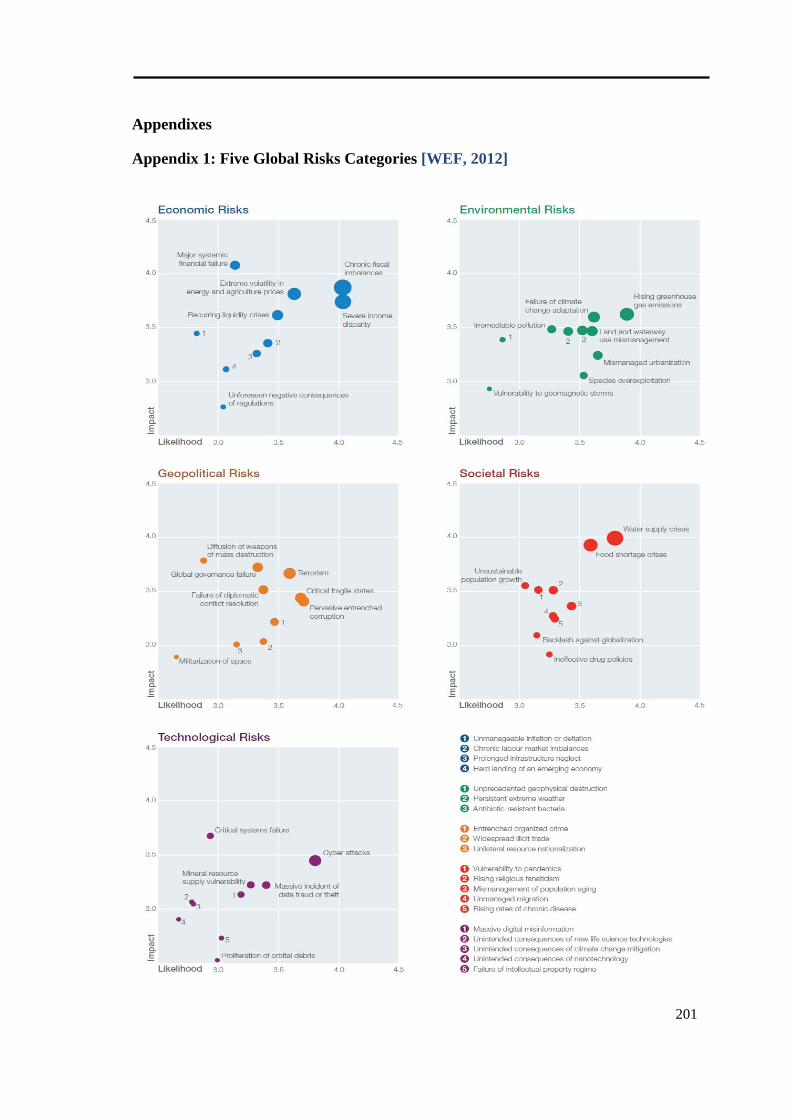
201
Appendixes
Appendix 1: Five Global Risks Categories [WEF, 2012]
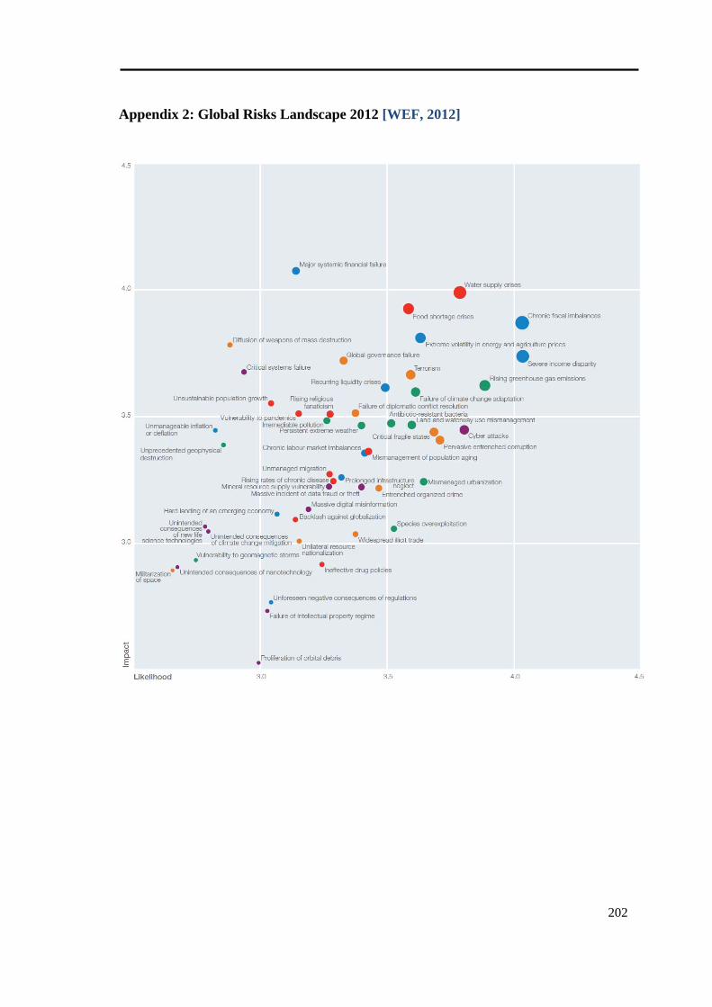
202
Appendix 2: Global Risks Landscape 2012 [WEF, 2012]
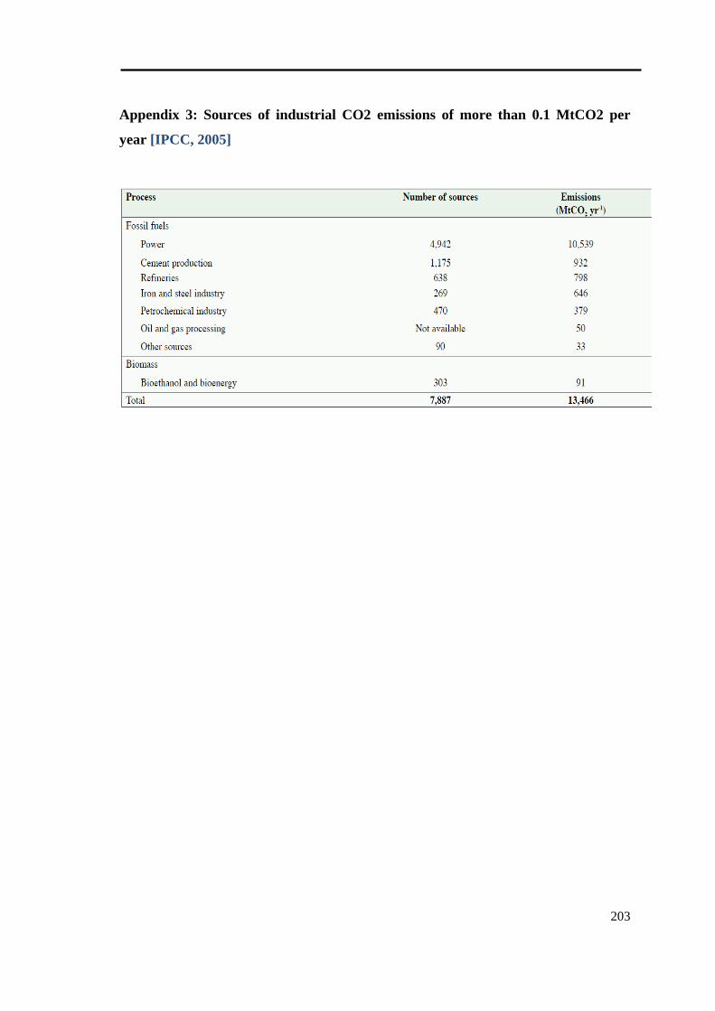
203
Appendix 3: Sources of industrial CO2 emissions of more than 0.1 MtCO2 per
year [IPCC, 2005]
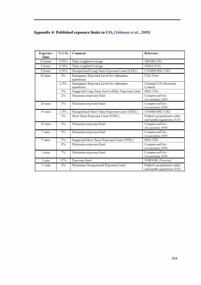
204
Appendix 4: Published exposure limits to CO2 [Johnsen et al., 2009]
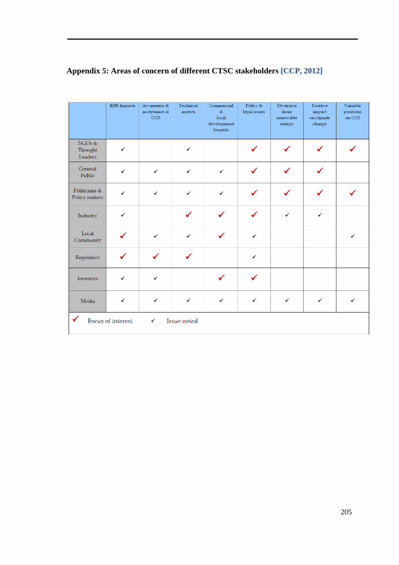
205
Appendix 5: Areas of concern of different CTSC stakeholders [CCP, 2012]
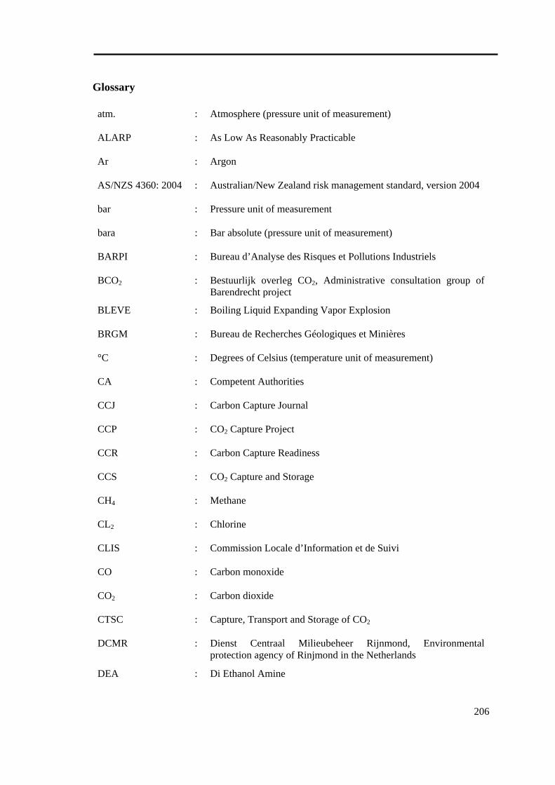
206
Glossary
atm. : Atmosphere (pressure unit of measurement)
ALARP : As Low As Reasonably Practicable
Ar : Argon
AS/NZS 4360: 2004 : Australian/New Zealand risk management standard, version 2004
bar : Pressure unit of measurement
bara : Bar absolute (pressure unit of measurement)
BARPI : Bureau d’Analyse des Risques et Pollutions Industriels
BCO2 : Bestuurlijk overleg CO2, Administrative consultation group of Barendrecht project
BLEVE : Boiling Liquid Expanding Vapor Explosion
BRGM : Bureau de Recherches Géologiques et Minières
°C : Degrees of Celsius (temperature unit of measurement)
CA : Competent Authorities
CCJ : Carbon Capture Journal
CCP : CO2 Capture Project
CCR : Carbon Capture Readiness
CCS : CO2 Capture and Storage
CH4 : Methane
CL2 : Chlorine
CLIS : Commission Locale d’Information et de Suivi
CO : Carbon monoxide
CO2 : Carbon dioxide
CTSC : Capture, Transport and Storage of CO2
DCMR : Dienst Centraal Milieubeheer Rijnmond, Environmental protection agency of Rinjmond in the Netherlands
DEA : Di Ethanol Amine
207
DECC : Department of Energy and Climate Change
DNV : Det Norske Veritas
DRIRE : Direction Régionale de l’Industrie, de la Recherche et de l’Environnement
ECBM : Enhanced Coal Bed Methane recovery
EIA : Environmental Impact Assessment
EOR : Enhanced Oil Recovery
ESD : Emergency Shut Down
EU : European Union
EZ : The Netherlands Ministry of Economic Affairs
FEED : Front End Engineering Design
FEP : Features, Events, Processes
FMEA : Failure Modes and Effect Analysis
FMECA : Failure Modes and Effect Criticality Analysis
FTA : Fault Tree Analysis
GCCSI : Global CO2 Capture and Storage Institute
GESIP : Groupe d’Etudes de Sécurité des Industries Pétroliers et chimiques
GHG : Green House Gas
Gt : Giga (1012) tonnes
H2 : Hydrogen
H2O : Water
H2S : Hydrogen Sulfide
HAZOP : HAZard and OPerability study
HSE : Health, Safety and Environment
ICPE : Installation Classée pour la Protection de l’Environnement
IEA : International Energy Agency
208
IEC 60300-3-9:1995 : International Electrotechnical Commission standard for risk management. Guide to risk analysis of technological systems, version 1995
INERIS : Institut National de l’Envi Ronnement Industriel et des RisqueS
IPCC : Intergovernmental Panel on Climate Change
IPPC : Integrated Pollution Prevention and Control
IRGC : International Risk Governance Council
ISO/IEC 73: 2002 : International standard for risk management – Vocabulary – Guidelines for use in standards, version 2002
km : Kilometer
km2 : Square kilometer
LNG : Liquified Natural Gas
LSIP : Large Scale Integrated Project
m : meter
max. : maximum
MDEA : Methyl Di Ethanol Amine
MEA : Mono Ethanol Amine
MIT : Massachusetts Institute of Technology
Mt : Million (106) tonnes
Mtpa : Million tonnes per annum
MW : Molecular Weight
N2 : Nitrogen
NAM : Netherlandse Aardolie Maatschappij BV, the Netherlands biggest oil and natural gas producer
NASA : US National Aeronautics and Space Administration
NGO : Non Governmental Organization
NO : Nitrogen mono-oxide
NO2 : Nitrogen di-oxide
NOx : Nitrogen Oxides (NO or NO2)
209
O2 : Oxygen
OCAP : Organic CO2 for Assimilation of Plants, Shell’s joint venture for CO2 transport in Barendrecht project
OECD : Organization for Economic Co-operation and Development
ppm : Parts per million
PRA : Probabilistic Risk Assessment
PTRC : Petroleum Technology Research Center
QRA : Quantitative Risk Assessment
R&D : Research & Development
SO2 : Sulfur dioxide
SO3 : Sulfur trioxide
SOx : Sulfur Oxides (SO2 or SO3)
STAMP : Systems-Theoretic Accident Model and Processes
STEL : Short Term Exposure Limit
STPA : Systems-Theoretic Process Analysis
SWOT : Strengths, Weaknesses, Opportunities and Threats
t : tonnes
UK : United Kingdom
UNFCCC : United Nations Framework Convention on Climate Change
US : United States of America
US$ : United States dolor
vol% : Volume percent
VROM : The Netherlands Ministry of Housing, Spatial Planning and Environment
WEF : World Economic Forum
Développement d’une approche systémique de management des risques pour les projets de CTSC
RESUME : Cette thèse concerne l’étude des risques associés aux projets de CTSC (Captage, Transport et Stockage de CO2) dont le développement est prévu à l’échelle industrielle. Les projets de CTSC sont des systèmes sociotechniques complexes pour lesquels une approche systémique de management des risques est nécessaire. L’approche doit couvrir les différents aspects du risque pour analyser l’influence de la dynamique des risques sur la dynamique des projets. Une méthodologie systémique de management des risques est proposée. Cette méthodologie est fondée sur les concepts de la pensée systémique, de l’approche STAMP (Systems-Theoretic Accident Model and Processes) développée au sein du Massachusetts Institute of Technology, et de la dynamique des systèmes. L'objectif est de modéliser et d'analyser la structure de contrôle de sécurité impliquée dans un projet de CTSC. La structure de contrôle de sécurité est la structure organisationnelle des parties prenantes (contrôleurs) qui sont responsables de maintenir les contraintes de la sécurité. L'objectif de cette structure de contrôle de sécurité dans cette thèse est d’éviter le retard ou l’échec des projets de CTSC. Cet objectif a été reformulé comme étant la définition et le management des risques majeurs qui pourraient empêcher ou limiter le maintien des contraintes de sécurité. Les risques ont été d’abord identifiés et classés selon huit catégories : Technique, SSE (Santé, Sécurité et Environnement), Politique/Stratégie, Réglementation, Organisationnel/Humain, Financier/Economique, Social et Projet. Les risques majeurs liés aux phases amont ont été extraits et modélisés en utilisant la méthodologie proposée. Les rétroactions affectant la propagation et l'amplification de chaque risque ont été étudiées. Les structures de contrôle de sécurité, le contexte et les risques associés des projets de Barendrecht, de Lacq et de Weyburn ont été analysés. L’application de la méthodologie sur ces trois retours d’expériences permet de proposer un modèle générique de contrôle de sécurité pour les projets de CTSC. L'accent est mis sur le rôle majeur des facteurs endogènes conduisant à l’échec des projets de CTSC. Ce modèle met en évidence les flux d'information et de communication entre les parties prenantes qui conduisent à améliorer leurs modèles mentaux et leurs décisions.
Mots clés : CTSC (Captage, Transport et Stockage de CO2), Management des Risques, Systémique, STAMP, Dynamique des Systèmes, Modélisation, Structure de Contrôle de Sécurité
Development of a Systemic Risk Management Approach for CTSC Projects
ABSTRACT: This thesis is concerned with understanding the risks associated with the development of CTSC (Capture, Transport & Storage of CO2) projects up to industrial scales. CTSC projects are complex sociotechnical systems for which a systemic risk management approach is required. The approach has to cover different aspects of risk in order to analyze how dynamics of risks affect dynamics of projects. A systemic risk management framework is proposed based on the concepts of systems thinking, STAMP (Systems-Theoretic Accident Model and Processes), developed at the Massachusetts Institute of Technology, and system dynamics. The objective is to model and analyze the safety control structure involved in a CTSC project. Safety control structure is the organizational structure of stakeholders (controllers) who are responsible for maintaining safety constraints. The goal of safety control structure in this work is to prevent CTSC project delay or failure. This goal has been rephrased as definition and treatment of major risks that could avoid maintaining safety constraints. The risks have been firstly identified and classified in eight main categories including Technical, HSE (Health, Safety and Environment), Policy/Strategy, Legal, Organizational/Human, Financial/Economic, Social and Project. The major risks related to the phases prior to engineering have been extracted and modeled by the proposed methodology. Feedback networks affecting the amplification of each risk have been studied. Safety control structures, context and associated risks of Barendrecht, Lacq and Weyburn projects have been analyzed in order to propose a generic safety control model for CTSC projects. Emphasis is placed on the significance of finding endogenous explanations for the failure of CTSC projects. The model highlights the flow of information and communication among stakeholders leading to improve their mental models and decisions.
Keywords: CTSC (Capture, Transport and Storage of CO2), Risk Management, Systemic, STAMP, System Dynamics, Modeling, Safety Control Structure