Embed Size (px)
Citation preview
Manufacturing for the Hydrogen Economy
Manufacturing Research & Development of PEM Fuel Cell Systems
for Transportation Applications
Background Material for the Manufacturing R&D Workshop to be held July 13-14, 2005
Washington, DC
July 7, 2005
Introduction In his 2003 State of the Union Address, President Bush announced a $1.2 billion Hydrogen Fuel Initiative to accelerate the development of the hydrogen and fuel cell technologies needed to move the United States toward a future hydrogen economy. While many scientific, technical, and institutional challenges must be overcome to realize the vision of a hydrogen energy economy, moving from today’s laboratory-scale fabrication technologies to high-volume commercial manufacturing has been identified as one potential roadblock to a future hydrogen economy.
The Workshop The Federal Interagency Working Group on Manufacturing for the Hydrogen Economy was established to coordinate and leverage the current federal efforts focused on manufacturability issues such as low-cost, high-volume manufacturing systems, advanced manufacturing technologies, manufacturing infrastructure, and measurements and standards. Participants in this working group include the Department of Energy (DOE -lead organization), Department of Agriculture, Department of Commerce/National Institute of Standards (NIST), Department of Defense, Department of Transportation, Environmental Protection Agency, National Aeronautics and Space Administration, National Science Foundation, Office of Management and Budget, and White House Office of Science and Technology Policy. Over the last year, this working group has been laying the groundwork for developing a roadmap to coordinate and guide research and development (R&D) efforts on manufacturing technologies critical to commercializing hydrogen and fuel cell technologies. The Roadmap Workshop on Manufacturing Technologies for the Hydrogen Economy is the next step in this process.
The purpose of the Manufacturing R&D workshop is to bring together industry, university and government representatives to discuss the key issues facing all aspects of manufacturing for hydrogen products including: (1) fuel cells that convert hydrogen into electric energy, (2) hydrogen storage systems, and (3) large-scale hydrogen production and delivery systems. The recommendations resulting from this workshop, which will outline the key technical problems facing the manufacture of hydrogen systems today and identify priorities for research and development on manufacturing during the transition to a hydrogen economy (e.g., 2005-2025), will be incorporated into the R&D Roadmap on Manufacturing Technologies for the Hydrogen Economy. This roadmap will be used to guide R&D on critical manufacturing technologies and technical standards required for high-volume production, and to direct future public-private partnerships that will facilitate transfer of technology to industry through cost-shared projects.
Purpose of This Document This document on manufacturing R&D for proton exchange membrane (PEM) fuel cell systems is one of three documents that have been prepared for the Workshop on Manufacturing R&D for the Hydrogen Economy. The other two documents cover manufacturing R&D for systems that store hydrogen and for systems that produce and distribute hydrogen.
This material is intended to provide information to workshop participants for their use prior to and during the workshop. This paper was written by the DOE roadmap team and NIST in consultation with industry participants.
The paper covers the following topics that will be addressed in the workshop:
• What hydrogen system components need to be manufactured to begin the transition from petroleum to hydrogen between now and 2025?
• What is the state of manufacturing technologies for these components and systems?
In addition, the workshop will identify and prioritize topics for public-private R&D on manufacturing of PEM fuel cells.
Fuel Cell System Components and Manufacturing Processes The PEM fuel cell powerplant is built from four main subsystems: (1) the cell stack, (2) the balance-of-plant, (3) power conditioning, and (4) system controls. Hydrogen storage is considered separately from the powerplant and, for the purposes of this document, represents a separate system that delivers “fuel cell quality” hydrogen to the powerplant. In this analysis, the air delivery system to the fuel cell is an integral part of the balance-of-plant.
Page 2 of 23
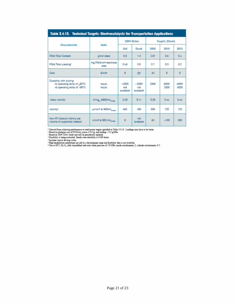
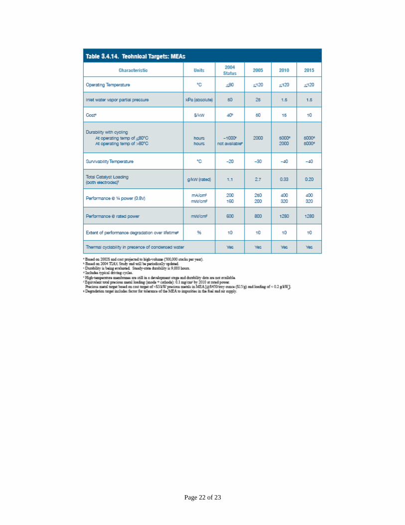
Cell Stack The cell stack has received the greatest amount of research and development attention because within the cell stack is the “heart” of the fuel cell; i.e., the electrochemical process. The technical targets for the cell stack are given in Attachment A.
Membrane Electrode Assembly The membrane electrode assembly (MEA) is a five-layer structure as shown in Figure 1. The inner structure consists of a membrane with each face covered by a catalyst layer and this layer is identified as a catalyst-coated membrane. In today’s technology, the membrane is Nafion® perfluorosulfonic acid, and the membrane thickness ranges from 25 to 50 micrometers. The catalyst-coated membrane is basically a thin film sandwich that could require thin film manufacturing processing; possibly roll-to-roll processing coupled with deposition processes such as ink jet printing.
The catalyst layers adjacent to each face of the membrane are platinum supported on carbon (~50 wt %) at a loading of equal to or less then 0.4 mg Pt/cm2. The thickness of the catalyst layer can approach 25 micrometers but is usually thinner. The outer two layers of the five-layer structure are the gas diffusion layers (GDLs), each adjacent to a catalyst layer. The GDLs are considerably thicker porous carbon layers with thickness in the range 300 micrometers per layer. Woven carbon/graphite cloths and carbon felts are promising technologies for manufacturing GDLs. The carbon felts are manufactured using paper processing techniques. For many fuel cells, the GDL is chemically treated to control its hydrophobic/hydrophilic properties. Thin film manufacturing processes such as vapor / physical deposition could be used to apply the hydrophobic/hydrophilic properties.
Membrane The Nafion® membrane is an expensive component for the fuel cell1. DuPont reports2 that improvements in the processing efficiencies and a potential reduction in materials cost will permit Nafion® to achieve the cost targets consistent with the hydrogen economy specifications. Arkema3, PolyFuel™4, and others propose alternative membrane materials to replace Nafion®. Reduced cost is the primary driver for alternative membrane manufacture, and the above researchers propose cost reductions by a factor of 4 to an order of magnitude compared to Nafion®. The alternative films have yet to be proven as replacements for Nafion® and until proven remain a development activity outside the scope of this manufacturing, fabrication, and assembly workshop.
Polymer processing research and development would help drive the cost of the Nafion® membrane to levels consistent with achieving the hydrogen economy goals. Roll-to-roll 1 E. Carlson, “Cost Analysis of Fuel Cell Stacks/Systems”, TIAX, LLC, 2003 Hydrogen and Fuel Cells Merit Review Meeting, Berkeley, CA, May 19-22 2 D. Lousenberg, T. Henry, D. Curtin, M. Tisack, P. Tangeman, “DIFFERIENTIATED MEMBRANES AND DISPERSIONS FOR COMMERCIAL PEM FUEL CELL AND ELECTROLYSIS SYSTEMS”, DuPont - Fayetteville Works, Fayetteville, NC, 2003 FUEL CELL SEMINAR ABSTRACTS 3 Gaboury, Scott, “”Development of a Low-Cost, Durable Membrane and MEA for Stationary and Mobile Fuel Cell Applications”, Atofina Chemicals, Inc. (Arkema Group), 2004 Annual Program Review Meeting May 24-27, 2004, Philadelphia, PA 4 http://www.polyfuel.com/technology/hydrogen.html
Page 3 of 23
processes are easily capable of handling multiple 25 micrometer films and this is another area that may provide a pathway to low cost membranes.
Catalyst and Catalyst Layers Cost drivers for the catalyst layer are materials (precious metal) costs, process cost to apply the catalyst to the carbon support, and process cost to deposit the carbon supported catalyst to the membrane. The latter identifies the importance of developing thin film manufacturing methods for fuel cells. For processing supported catalyst, the catalyst is typically applied to carbon using a batch, wet chemistry method. Alternative, high throughput methods to prepare supported catalyst would decrease the cost of supported catalyst manufacture. Deposition methods, such as ink jet printing, vapor deposition, physical deposition, and semiconductor processing technology, offer alternative manufacturing approaches that could drive down cost.
Seals There is approximately one mile of sealant in an 80 kW transportation fuel cell stack. Because of the large number of seals, the development of high-speed seal applications is necessary. Integrating the sealing process with the manufacturing of MEAs is an obvious, but possibly difficult method to develop. Thin film manufacturing processes, e.g., screen printing, and coating process such as spray coating or roll coating, may offer opportunities for low cost manufacture of seals for the MEAs.
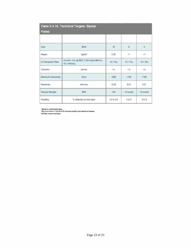
Bipolar Plates Both graphite and metal bipolar plates are proposed for PEM fuel cells and the technology has not progressed to the stage where the superior approach can be identified. There are some fundamental and common properties associated with all bipolar plates: flatness, parallelism of the faces, and uniformity of the flow fields.
The ability to manufacture plates without post machining or grinding to assure flatness and parallelism is a critical need. A 25 micrometer increase in thickness at one corner of a bipolar plate, when repeated in a cell stack, could result in a 10 cm tilt in an 80 kW stack (approximately 400 cells). Building a cell stack with such a repeatable, uncontrolled variation would obviously not be feasible. The importance of tolerance control is demonstrated. Lack of tolerance control in the manufacture of the flow fields can produce uneven distributions of the reactants5. Performance, durability, and life of the fuel cell will all be impacted by the uneven distribution of the reactants. Precise control of the dimensions of the flow fields is critical for the manufacture of bipolar plates.
The fuel cell R&D community has proposed rapid, high rate manufacture of metal and graphite bipolar plates. Stamping of the metal plates will require exacting control of the plate configuration and dimensions. Injection molding of carbon- and graphite-containing resins is an approach for high rate forming of graphitic bipolar plates. Fabrication research and development is important for establishing methods that can maintain the exacting dimensions and physical properties of bipolar plates.
5 Kelly, Kenneth J., et. al, “Application of Advanced CAE Methods for Quality and Durability of Fuel Cell Components” 2005 Annual Program Review Meeting May 23-26, 2005 in Arlington, Virginia
Page 4 of 23
For some bipolar plates, surface treatments are required to control corrosion and/or the hydrophobic/hydrophilic properties of bipolar plates. Physical and vapor deposition processes and heat treatment manufacturing approaches need to be established. These surface treatment methods must provide high rate delivery while maintaining the physical and chemical properties of the bipolar plates. Technology developed for photovoltaic processing and for the semiconductor industry may find application in the manufacture of bipolar plates.
Reactant Manifolds Two types of reactant manifolds are common for PEM fuel cell stacks: internal manifolds and external manifolds.
Internal Manifolds
• Fabrication of the reactant manifolds for internally sealed designs is a critical part of the manufacture of the bipolar plates, discussed above.
• Complex metal stampings methods will be necessary to fabricate the metal bipolar plate with internal manifolds and precise flow fields.
• Molding or pressing of graphite plates with complex geometries containing internal manifolds will be a requirement for PEM stacks with graphite bipolar plates.
• The application of seals is critical to the manufacturing process and must assure complete segregation of the reactants and prevent cooling liquids from contaminating the fuel cell.
External Manifolds
External reactant manifolds can be made from commercial-grade plastics using injection molding, thermoforming or alternative high-rate fabrication methods. Complex configurations may be required to assure the proper ducting of the reactants to the fuel cell stack. Sealing the reactant manifolds is critical to achieving the necessary performance. Integrating the sealing process with the manufacture of reactant manifolds is an obvious, but possibly difficult manufacturing method. Thin film manufacturing processing and coating processes may be required to achieve sealing quality for the reactant manifolds.
Cell Stack Assembly The construction of fuel cell stacks with multiple MEAs layered within the stack and under controlled stacking pressure demands exacting indexing of the MEAs, bipolar plates, and cooler plates. The applications of seals and spacers are an important but time-consuming process that assures indexing and alignment of the multilayered stack. The requirements of controlled stack load, i.e. uniform distribution of pressure between seals and adjacent active areas of MEAs, is decisive for optimum cell performance and eliminating reactant leaks. To achieve the controlled stack load, the height of the internal seals is controlled and matched to the electrode height and this provides a uniform flat/parallel face between cell components. Cell stacks with as many as four hundred
Page 5 of 23
individual cells (MEA with two bipolar plates) each separated by a cooler plate, are anticipated for the transportation applications.
Indexing the seals and adjacent cells prevents stresses that could fracture the carbon components or tear the fragile membrane. It will probably be necessary to control of the alignment to +/- 5 micrometers. Rapid assembly, while critical to low cost manufacture of stacks, is complicated by the indexing requirement.
Designs for manufacturing and assembly may provide pathways to high-rate construction of rugged fuel cell stack subsystems. Early application of design for manufacturability should shorten product development time and standardize tooling and components. Simplifying the design and development of standard manufacturing and repeatable processes is necessary to achieving cost reduction. Integrating functionality offers the prospect of additional production and assembly optimization. The integration could include the development of subsystems through a supplier network. The concept of establishing supply-based production is consistent with the principles of designs for manufacturability.
Quality Assurance Defining component, cell stack subsystems, and cell stack quality requirements together with the application of quality control practices will minimize, or possibly eliminate, the need for sampling and control testing of these components. Evaluating and incorporating manufacturing best practices, such as 5S, agile manufacturing, and six sigma / Statistical Process Control are necessary to the development of high rate manufacturing. A quality assurance program is vital for identifying methods that best use management by facts using six sigma, kaizen, and statistical analysis as applied to the cell stack and cell stack subsystems. Focusing on preventing defects in manufacturing processes would significantly advance cell stack fabrication and offer promise for anticipating and exceeding quality requirements while minimizing quality assurance costs.
Balance of Plant The balance-of-plant (BOP) has probably received the least amount of attention since a basic tenet of the of fuel cell manufacturers is that the assemblies within the balance-of-plant can be manufactured from existing technology. On the other hand, the balance-of-plant represents up to 50% of the overall cost of commercialized fuel cell powerplants. Ongoing research and development indicates a need for specialized BOP components, particularly in areas of compressors and expanders. The balance of plant specifically addresses supply and control of the reactants (air and hydrogen) and removal of the by-products (heat and water). Sensors to monitor and control the flow of reactants, the removal of by-products, temperature, and pressure are necessary components for the BOP.
Pre-treatment of the reactants could include filtering the air, pressurizing the air, controlling the flow rates of the reactants (utilization), and humidifying either or both of the reactants.
Page 6 of 23
By-product removal would include the following subsystems:
1. Heat (thermal management) including cell cooling (heating) subsystem and pre-heating of reactants.
2. Product water removal from cell, capture of the product water, and storage of the product water when necessary.
Reactant Delivery Subsystem Integrating the reactant delivery components into subsystems, air and hydrogen, or into a common subsystem that provides control and pretreatment separately to both reactants would greatly simplify the assembly of the PEM powerplant. Materials joining manufacturing methods and component integration to reduce the number of joining operations would greatly simplify the manufacture and assembly of the reactant delivery systems.
Development of rapid, low cost manufacturing methods for the physical sensors used in the air and hydrogen delivery systems will be required for PEM powerplants. Key factors measured by the advanced powerplant sensors include: humidity, pressure, temperature, and reactant flow. The application of MEMS to sensors will incorporate nanotechnology manufacturing. Semiconductor processing and photovoltaic fabrication methods can contribute to rapid, low cost manufacturing methods.
Air Delivery
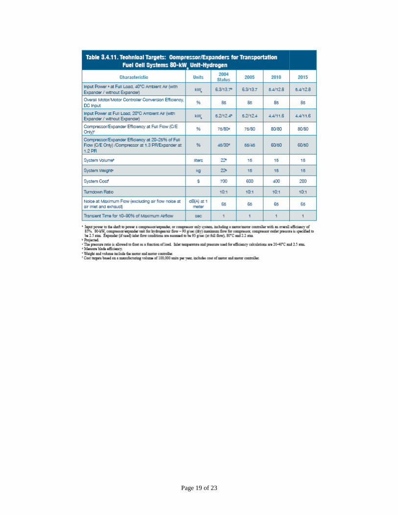
Current PEM powerplants often use off-the-shelf compressors or blowers that are not specifically designed for fuel cell applications, resulting in systems that are heavy, costly, and inefficient. Manufacturing research for low cost blowers, turbo-compressors, mass flow meters, pressure regulators, and humidification systems will be necessary to reduce the cost of these components. Technical targets for compressor/expanders are given in Attachment A.6
Rapid prototyping methods coupled with CAD processes could accelerate the development of designs for manufacturability of an air delivery system. Selective laser sintering and stereolithography could provide pathways to designs based on integration of components. Concepts such as indirect tooling provide reduced production cost for molding components. Sand casting, investment casting and vacuum casting offer promise for the indirect tooling to reduce component and subsystem cost.
Hydrogen Delivery
Manufacturing processes identified in the air delivery section offer benefits similar to the hydrogen delivery system. Hydrogen sensors and hydrogen recycle blowers are components requiring manufacturing development. Integrating the sensors into the cell stack components offers the opportunity to reduce assembly time. The use of rapid prototyping will benefit the development of these additional components.
6 The Hydrogen, Fuel Cells & Infrastructure Technologies Program Multi-Year Research, Development and Demonstration Plan, published in February 2005, http://www.eere.energy.gov/hydrogenandfuelcells/mypp/
Page 7 of 23
The development of recycle hydrogen blowers will require high quality, low-cost seals. The manufacture of zero-defect seals for the hydrogen delivery system in the PEM stack will be a target for PEM powerplants. The requirement of nanotechnology manufacturing methods for hydrogen sensors is consistent with needs of the physical sensors previously identified.
Thermal Management Subsystem Major components in the manufacture of the thermal management subsystem include the heat exchanger, cooling plates, energy management system (e.g. a contact cooler), and associated pumps and coolant follow controllers. Integrating these components into a subsystem and developing material joining methods and optimizing sealing systems could greatly enhance the manufacturability of the thermal management subsystem. Designs for manufacturability and assembly could simplify the manufacturing process and drive down manufacturing costs. Coupling rapid prototyping methods with CAD processes may provide a means to accelerate the development of low-cost manufacturing methods.
The manufacture of porous metal materials, metal foams, and microchannel components for heat exchangers is a potential area of interest. Applying selective laser sintering and stereolithography could provide pathways to design for manufacture concepts. Advanced manufacturing of 3-D-woven graphite fiber structures for heat exchanger applications is a fabrication method that needs to be proved.
By developing rapid methods for applying thermal insulation to fuel cell powerplants and components, manufacturers could lower assembly cost. Advanced manufacturing of thermal insulation systems integrated with the fabrication of components for the thermal management system offers a cost reduction approach.
Water Management Subsystems Water management is key technology for the PEM fuel cell. Reservoirs, accumulators, humidifiers, condensers, and associated pumps and controllers are the major components. Integrating the water management subsystem with the thermal management subsystem provides one avenue to simplify manufacturing and reduce cost.
Similar to the case of the thermal management subsystem, integrating the major components into a subsystem with minimal manufacturing efforts in the joining of components could lead to low-cost manufacture of the water management subsystem. Integrating the seal with subsystem design could permit us to rapidly assemble the many components in the water management subsystem. Low cost manufacturing methods for heat exchangers and condensers could build on the metal foam and graphite structures identified in the thermal management section.
Manufacturing wettable coatings that promote the transfer of water through bipolar plates and coolers and prevent the build up of liquid water barriers in the water management system could be approached using vapor deposition or physical deposition technologies.
Page 8 of 23
Power Conditioning The fuel cell power conditioning subsystem converts the low-voltage DC power produced by a fuel cell into high voltage power consistent with the transportation requirements. The first stage is the DC/DC boost that will increase the fuel cell stack voltage to a higher voltage. Energy storage to assist in responding to rapid transients would include batteries, super capacitors, or ultra capacitors. The final stage in the power conditioner is to develop regulated power, either through a DC/DC converter or a DC/AC converter7. The power conditioning unit also controls feedback into the fuel cell and maintains the harmonics at acceptable levels.
The manufacture of integrated power conditioning systems is a well established industry. Engaging the power conditioner industry into transportation fuel cell applications is a pathway for advancing fuel cell power conditioning.
System Controls System controls for the powerplant are built on computer interfacing between the vehicle and the powerplant to achieve optimum performance of the overall vehicle system. Developing integrated circuits dedicated to the operation and interfacing of the PEM powerplant offers us the opportunity for low-cost system controls. Remote monitoring of major subsystems and components using “Bluetooth-like” wireless communications offers the opportunity for low cost assembly of control systems in the powerplant and vehicle. These approaches to low cost system controls would build on existing and emerging technology for traditional ICE vehicles.
Cross Cutting Issues (prepared by NIST) As outlined in the previous section, manufacturing for the hydrogen economy covers a large spectrum of manufacturing technologies, from continuous chemical processes to discrete mechanical fabrication processes. As such, there are diverse issues and challenges associated with each of these manufacturing technologies. However, there are significant mutual influences among these technologies to affect the overall feasibility of the hydrogen economy. For example, while some continuous chemical process technologies rely on advances in discrete mechanical fabrication for cost reductions (e.g. fuel injectors used in gasifiers, feed systems) other discrete manufacturing technologies benefit from advances in continuous processes (e.g. gas purity, water management). Thus, the working group is able to identify a small set of challenges that are applicable to most of the manufacturing technologies. This section provides a preliminary summary of these cross cutting issues.
7 “In some fuel cell vehicle applications the fuel cell’s DC power is converted to alternating current (AC) to run AC induction motors, requiring the use of AC motor controllers. In other cases, DC motors are used, governed by DC motor control systems.” from Fuel Cell Power for Vehicles, U.S. Fuel Cell Council, Spring 2001, http://www.usfcc.com/USFCC-TransportationBrochure.pdf
Page 9 of 23
Metrology and Standards Metrology provides quantitative information about a manufacturing process and its output. Thus it is key to understanding and improving any manufacturing technology. The ability to reliably measure various process parameters and other critical manufacturing process outputs enables cost effective manufacturing. Specific metrology needs of manufacturing for the hydrogen economy include the areas of dimension and form of components, micro structures and surfaces, particle size and distribution, thin and thick film coatings, pressure, temperature, vacuum, gas flow, water transport, resistance, conductivity, and electrical power.
Related issues include the need for standard measurement methods and protocols for these properties. Such standards ensure quality in the supply chain, lower costs, enhance international trade, and improve the quality of the end products.
Modeling and Simulation Modeling and simulation can significantly advance the development and optimization of manufacturing processes, and thus are key elements in the development of a viable manufacturing for hydrogen economy.
Knowledge Bases To support modeling efforts, there is a need for information and knowledge about new materials and sealants, including their processibility, formability, machinability, and compatibility with other materials and gases. There is also a need for new process technologies, fundamental correlations between manufacturing parameters, and performance parameters. Creating pre-competitive, easily accessible, user-friendly knowledge bases for the use of the hydrogen industry will foster further innovation in this area.
Design for Manufacturing and Assembly In order to cost effectively move from existing small-batch production to high-volume production, design-for-manufacturing (DFM) methodologies have to be used at the earliest stages of product development. DFM principles that should be considered include component selection for reduced parts counts designs that can be produced consistently at both low and high volumes, and realistic tolerance analysis and specifications.
Sensing and Process Control Sensors and process control technologies are key enablers for increasing the reliability and quality of manufacturing processes while reducing cost. Low cost sensing and sensor fusion technologies with reliable sensor networks are therefore needed for in-process sensing of processes and in-operation sensing of product performance.
Page 10 of 23
State of Manufacturing Fuel cell stacks and their respective components are in the early stages of manufacturing. Fuel cells are now manufactured using laboratory fabrication methods that have been typically scaled up in size, but do not incorporate high volume manufacturing methods. As an example, for fuel cells based on PEM technology, the assembly of membrane electrode structures (including the gas diffusion layer)—a five-layer structure—is accomplished in five separate stages. The multi-layer structure is then hot pressed to bond the layers together. The bonding is affected by the edge seal material, which typically has thermal set or thermal plastic properties. The final product is called, depending on manufacturer, a unified electrode assembly or unified cell device, UCD. All of these steps are conducted as discrete operations with most of the actual labor done by hand; indexing the anode and cathode layers is, of course, very time intensive.
Precious metal catalysts contribute significantly to the overall cost of fuel cells. Recognized, reliable, and repeatable measurement technologies and methodologies that would allow catalyst application within fuel cell stacks to be optimized would greatly reduce fuel cell cost from both a materials and process perspective.
Assembling the fuel cell stack requires exacting control of the layout of the individual UCDs to ensure direct alignment of the electrodes in adjacent cells. Between the UCDs is the bipolar plate whose flow fields are again carefully indexed. For cells with internal manifolds, sealing the bipolar plate to the UCDs is critical to avoid mixing of reactant gases. An additional component for the stack is the cooler plate, which like the bipolar plate must maintain strict flatness and parallelism tolerances. Assembly requires that manufacturers repeatedly measure stack components and close tolerances for seal connections to assure quality and performance are maintained. Manufacturing ancillary equipment such as compressors, flow controllers, and converters must also be addressed.
As fuel cell manufacturing scales up, it is also imperative that we understand the relationships between fuel cell system performaparameters and variability. Such understanding major role in fuel cell design, tolerances, and spimplementing design for manufacturability. Modsignificant role in developing this understanding
Page 11 of
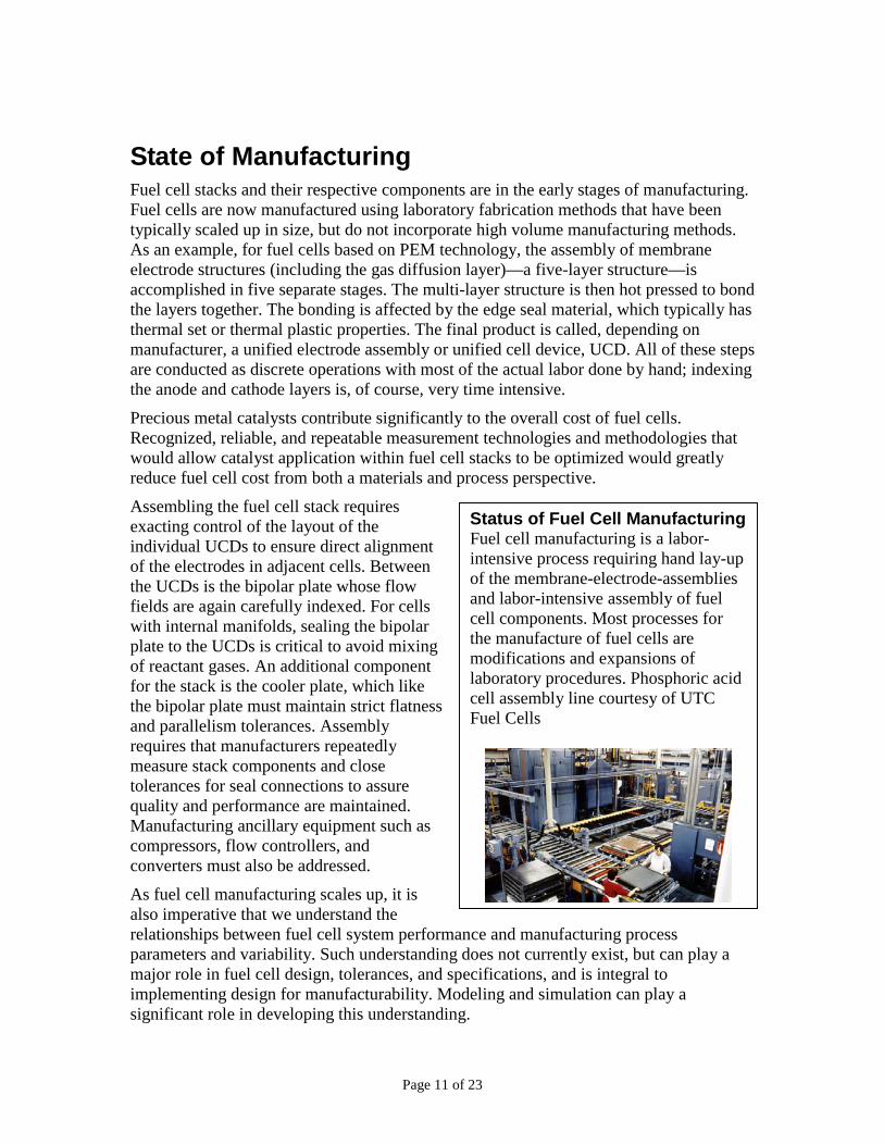
Status of Fuel Cell ManufacturingFuel cell manufacturing is a labor-intensive process requiring hand lay-up of the membrane-electrode-assemblies and labor-intensive assembly of fuel cell components. Most processes for the manufacture of fuel cells are modifications and expansions of laboratory procedures. Phosphoric acid cell assembly line courtesy of UTC Fuel Cells
nce and manufacturing process does not currently exist, but can play a ecifications, and is integral to eling and simulation can play a .
23
Major subsystem components such as the air delivery system and the cooling system are each individually assembled by joining components, e.g., connecting the heat exchangers to the coolant system or integrating the humidification system with the air blower. Construction of the power plant is usually done through the integration of subsystems; however each subsystem is assembled separately by a labor-intensive process. Gas, water, and coolant manifolds are constructed on-site. To weld and join components, each connector must be separately cut, prepared, and joined to the subsystem. Prefabrication of components and the molding of components are limited if used at all. A lack of component standardization is one reason for the limited manufacturing capability.
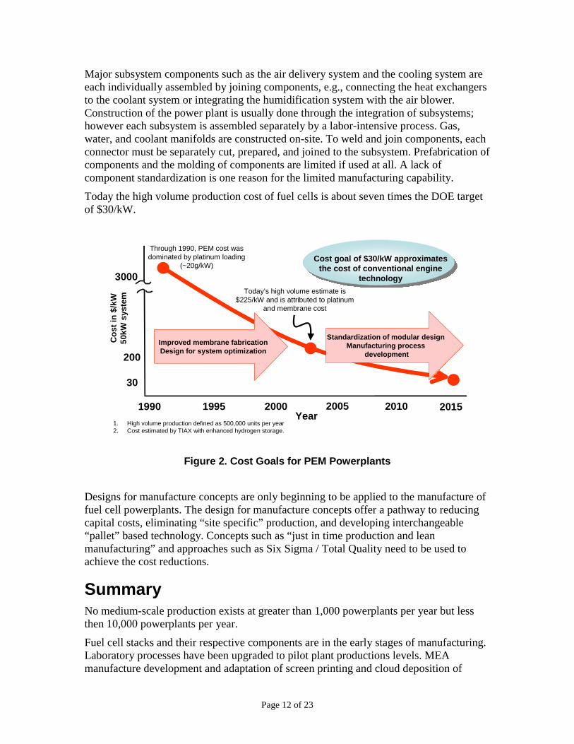
Today the high volume production cost of fuel cells is about seven times the DOE target of $30/kW.
1. High volume production defined as 500,000 units per year2. Cost estimated by TIAX with enhanced hydrogen storage.
20151990 2000Year
20051995 2010
30
200
3000
Cos
t in
$/kW
50kW
sys
tem
Through 1990, PEM cost was dominated by platinum loading
(~20g/kW)
Today’s high volume estimate is $225/kW and is attributed to platinum
and membrane cost
Improved membrane fabricationDesign for system optimization
Standardization of modular design Manufacturing process
development
Cost goal of $30/kW approximates the cost of conventional engine
technology
Figure 2. Cost Goals for PEM Powerplants
Designs for manufacture concepts are only beginning to be applied to the manufacture of fuel cell powerplants. The design for manufacture concepts offer a pathway to reducing capital costs, eliminating “site specific” production, and developing interchangeable “pallet” based technology. Concepts such as “just in time production and lean manufacturing” and approaches such as Six Sigma / Total Quality need to be used to achieve the cost reductions.
Summary No medium-scale production exists at greater than 1,000 powerplants per year but less then 10,000 powerplants per year.
Fuel cell stacks and their respective components are in the early stages of manufacturing. Laboratory processes have been upgraded to pilot plant productions levels. MEA manufacture development and adaptation of screen printing and cloud deposition of
Page 12 of 23
catalyst onto membranes or to roll-to-roll processing has not reached a mature stage. Robotic assembly and fabrication of stationary phosphoric acid powerplants have been successfully demonstrated but not at the high rates required for transportation applications.
Membrane production is dominated by the Chlor-Alkali industry that delivers a premium product at a premium cost. Nafion® for fuel cells remains a spin-off technology from this Chlor-Alkali manufacturing and scale-up of fuel cell grade Nafion® technology is not justified based on present fuel cell demand.
No medium scale production facilities capable of producing 1,000 powerplants per year exist. Investment in production facilities is only beginning to be acceptable based on the development status of fuel cell technologies for non-transportation applications.
The manufacturing technology most similar to fuel cell stacks is battery production, which already incorporates roll-to-roll processing. Photovoltaic and semiconductor device manufacturers have adapted thin film manufacturing to commercial processes; although their processing costs remain prohibitive compared to the targets for the transportation fuel cell.
Assembling fuel cell powerplants remains a labor intensive process. Current systems often use off-the-shelf components that are not specifically designed for fuel cell applications, resulting in systems that are heavy, costly, and inefficient.
The stationary powerplant producers are beginning to develop processes for manufacturing 1,000 to 10,000 powerplants per year. The stationary powerplant manufacturers provide a base for the transportation efforts; however these stationary efforts fall short of the one million or more powerplants per year necessary for transportation. Cost drivers for the stationary powerplants are approximately one order-of-magnitude higher than transportation cost targets; $500/kW compared to $30/kW.
Manufacturers anticipate building on the experience of the recording media, semiconductor industry, battery industry, and photovoltaic industry when developing manufacturing processes for PEM fuel cells. The development of supply networks within the North America can lead to the cost targets in Figure 2. A public-private partnership that includes industry, academia, and government provides the process for developing the PEM fuel cell transportation industry over the period 2006 through 2025. Generic, core process, metrology, and other critical manufacturing technologies and technical standards required for high-volume production, need to be developed by the federal government’s research institutions, and enabled by university research. To leverage government investment, cost-shared projects formed with the private sector would facilitate transfer of technology to industry.
Page 13 of 23
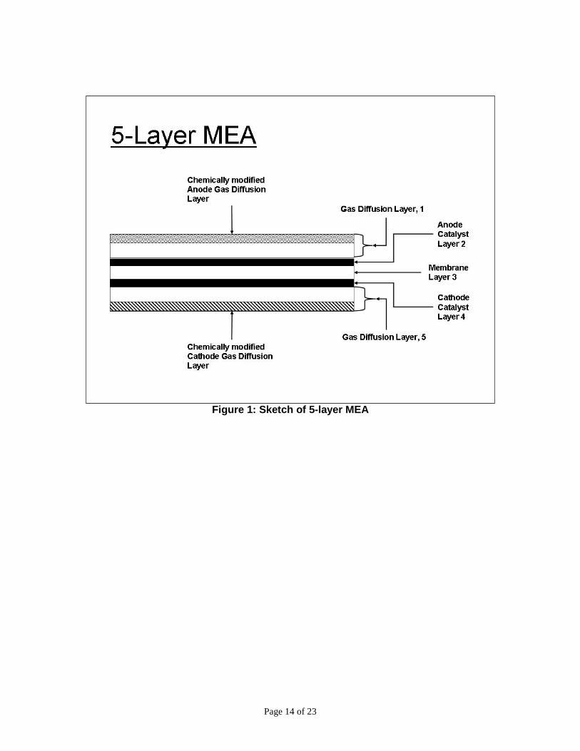
Figure 1: Sketch of 5-layer MEA
Page 14 of 23
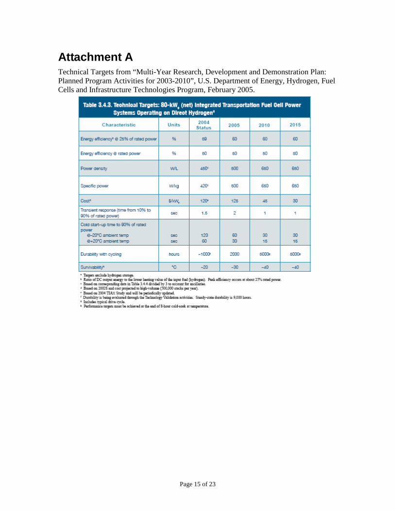
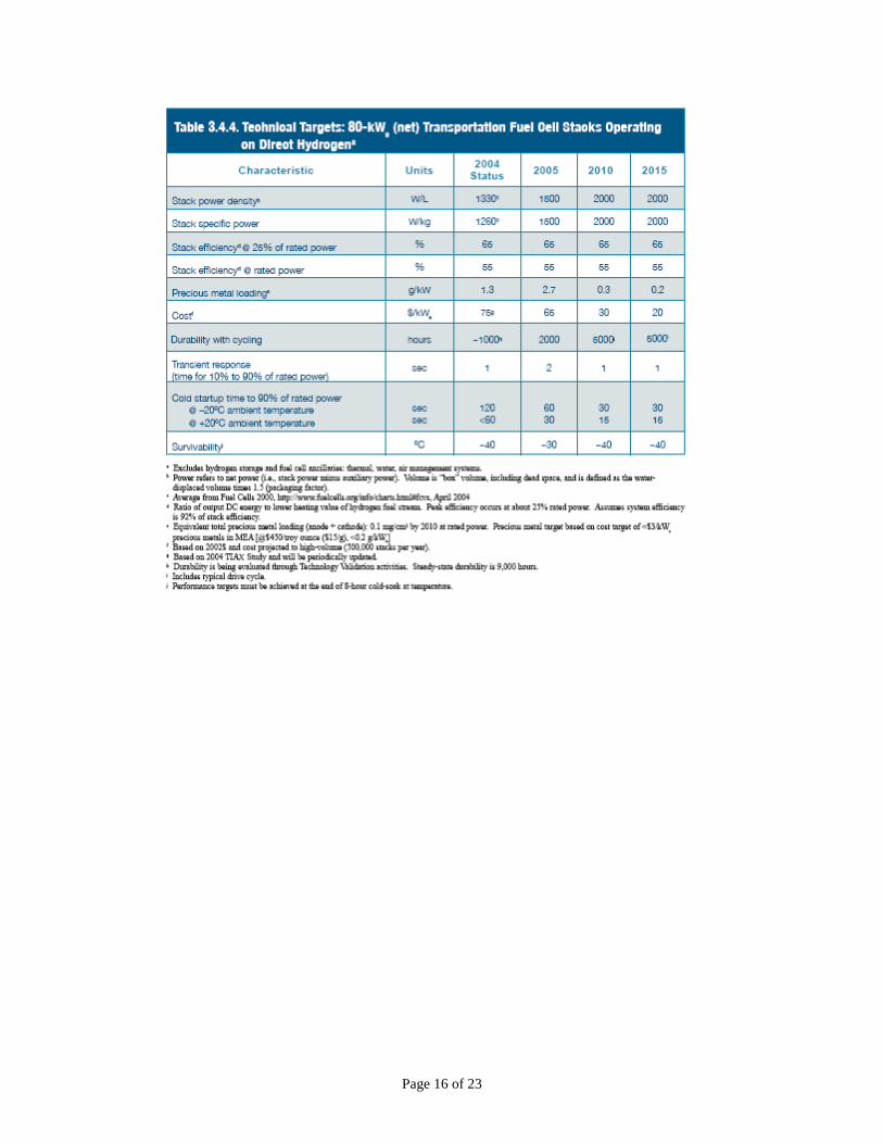
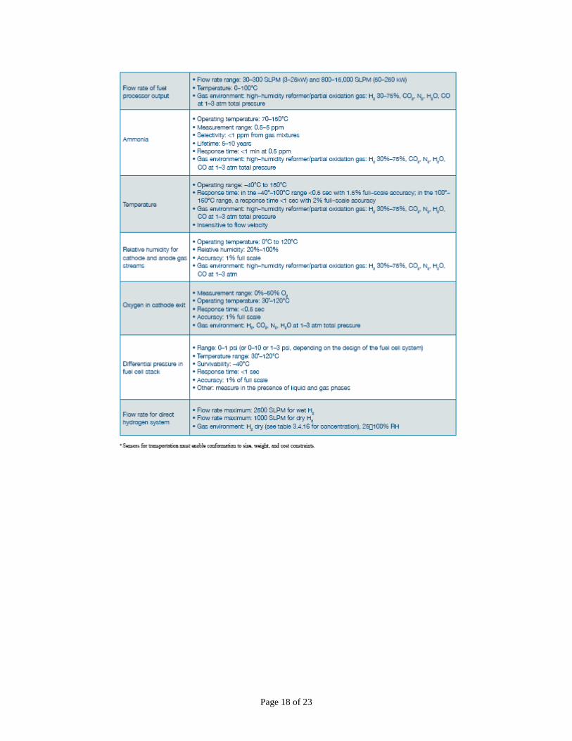
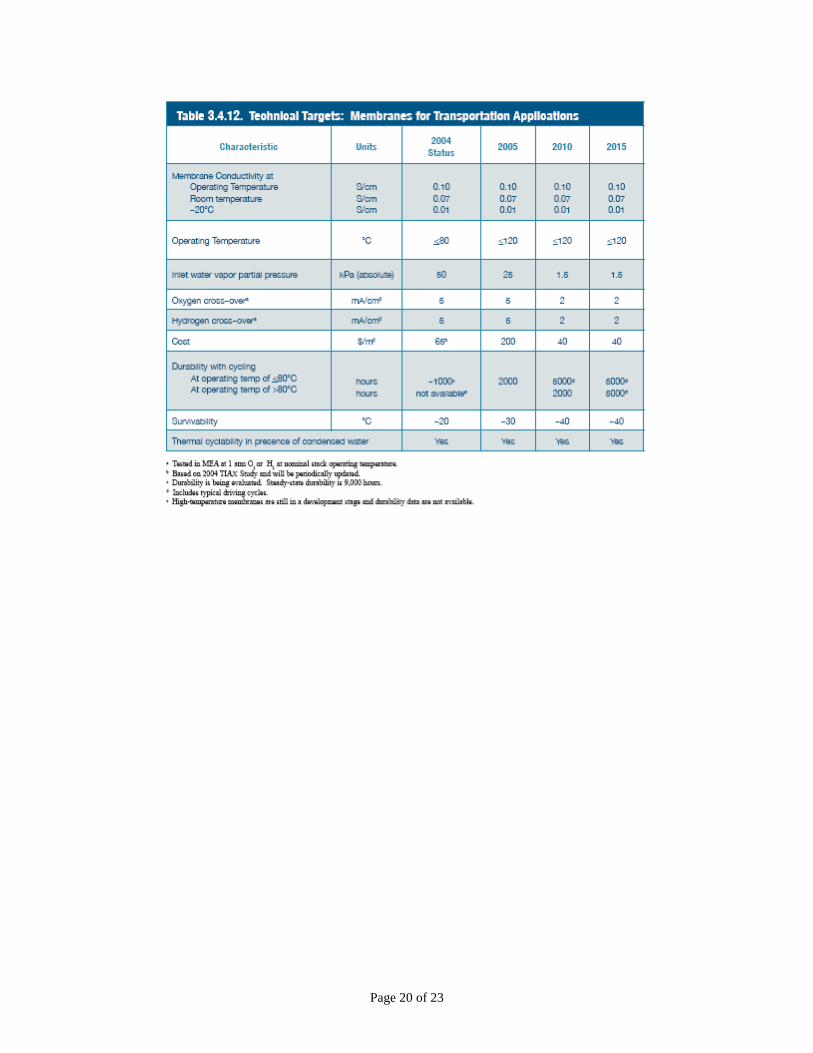
Attachment A Technical Targets from “Multi-Year Research, Development and Demonstration Plan: Planned Program Activities for 2003-2010”, U.S. Department of Energy, Hydrogen, Fuel Cells and Infrastructure Technologies Program, February 2005.
Page 15 of 23
Page 16 of 23
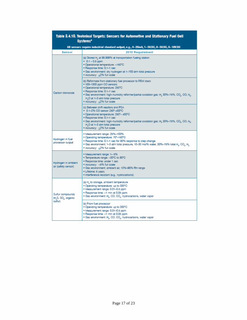
Page 17 of 23
Page 18 of 23
Page 19 of 23
Page 20 of 23
Page 21 of 23
Page 22 of 23
Page 23 of 23