Embed Size (px)
Citation preview
Printed by Jouve, 75001 PARIS (FR)
(19)EP
2 38
0 55
8B
2
(Cont. next page)
*EP002380558B2*(11) EP 2 380 558 B2
(12) NEW EUROPEAN PATENT SPECIFICATIONAfter opposition procedure
(45) Date of publication and mention of the opposition decision: 16.10.2019 Bulletin 2019/42
(45) Mention of the grant of the patent: 12.09.2012 Bulletin 2012/37
(21) Application number: 10252052.5
(22) Date of filing: 03.12.2010
(51) Int Cl.:A61K 9/107 (2006.01) A61K 39/39 (2006.01)
B01F 13/00 (2006.01) A61K 39/145 (2006.01)
B01F 3/08 (2006.01) B01F 5/06 (2006.01)
B01F 5/10 (2006.01) B01F 13/10 (2006.01)
A61K 9/00 (2006.01) B01F 7/00 (2006.01)
(54) Manufacturing of an emulsion under arrangement of interaction and back pressure chamber for microfluidization
Herstellung einer Emulsion unter Vorbereitung einer Interaktions- und Gegendruckkammer zur Mikroverflüssigung
Production d’une Emulsion par arrangement de chambres d’interaction et de contre pression pour la microfluidisation
(84) Designated Contracting States: AL AT BE BG CH CY CZ DE DK EE ES FI FR GB GR HR HU IE IS IT LI LT LU LV MC MK MT NL NO PL PT RO RS SE SI SK SM TR
(30) Priority: 03.12.2009 US 283548 P
(43) Date of publication of application: 26.10.2011 Bulletin 2011/43
(73) Proprietor: Novartis AG4056 Basel (CH)
(72) Inventors: • Rueckl, Harald
36304 Alsfeld (DE)• Scheffczik, Hanno
35039 Marburg (DE)
(74) Representative: Carpmaels & Ransford LLPOne Southampton RowLondon WC1B 5HA (GB)
(56) References cited: EP-A1- 0 770 422 EP-A2- 2 506 832WO-A1-90/14837 WO-A1-2009/132171WO-A2-2005/027872 WO-A2-2006/050837WO-A2-2008/051186 US-A1- 2004 258 701US-A1- 2004 258 701 US-A1- 2006 251 684
• PODDA, DEL GIUDICE: EXPERT REV VACCINES, vol. 2, 20 March 2001 (2001-03-20), pages 197-203, XP8099203,
• Microfluidics Corporation: "Innovation through Microfluidizer Processor Technology", Microfluidizer Processor User Guide, 1998,
• Microfluidics Corporation: "Innovation through Microfluidizer Processor Technology", Microfluidizer Processor User Guide, 2008,
• LIDGATE ET AL: Pharmaceutical Research, vol. 9, no. 7, 1992, pages 860-863,
• OTT ET AL: "MF59. DESIGN AND EVALUATION OF A SAFE AND POTENT ADJUVANT FOR HUMAN VACCINES", PHARMACEUTICAL BIOTECHNOLOGY, vol. 6, 1 January 1995 (1995-01-01), pages 277-296, XP001206665,
• OTT ET AL: "The Adjuvant MF59: A 10-Year Perspective", METHODS IN MOLECULAR MEDICINE. Humana Press, vol. 42, 15 April 2000 (2000-04-15), pages 211-228, XP002501687,
• Podda et al: "MF59 Adjuvant Emulsion. Chpt. 9. New Generation Vaccines.", , 2005,
• Avestin webpage: , Retrieved from the Internet: URL:www.avestin.com/English/staticvalvepag e.html
• Avestin webpage: , Retrieved from the Internet: URL:www.avestin.com/English/fx.html
• Information Disclosure Statement filed 8 November 2012 on US 12/928185
• JAFARI ET AL: food Hydrocolloids, vol. 22, 2008, pages 1191-1202,
• DRIESENS, J.: J. Clin. Microbiol., vol. 10975, no. 2,2 , pages 85-88,
• Information Disclosure Statement filed 8 February 2013 on US 12/928165
• ALLISON: Methods, vol. 19, 1999, pages 87-93,
2
EP 2 380 558 B2
• LITTLE ET AL: The Shorter Oxford English Dictionary. 3rd Edition, vol. 1073, no. 2 , page 1612,
• LITTLE ET AL: The Shorter Oxford English Dictionary. 3rd Edition, vol. 1073, no. 1 , page 751,
• LIDGATE D M et al: "DEVELOPMENT OF AN EMULSION-BASED MURAMYL DIPEPTIDE ADJUVANT FORMULATION FOR VACCINES", VACCINE DESIGN: THE SUBUNIT AND ADJUVANT APPROACH, 1 January 1995 (1995-01-01), pages 313-324, XP001248049,
• US provisional application 61/283,548 (priority document to EP2506822B)
• USPTO Patent assignment Abstract of Title relating to US 61/283,548
• Further submissions to USPTO by Novertis re addition of inventor and assignment of third inventor’s rights
• Declaration of Professor Robert J Fisher• BAUDNER, B. ET AL: Pharmaceutical Research,
vol. 26, no. 6, 2009, pages 1477-1485,• SEUBERT, A. ET AL: J. Immunol., vol. 180, no. 8,
2008, pages 5402-5412,• SCHULTZ, V. ET AL: VACCINE, vol. 26, 2008,
pages 3209-3222,• STREETER, V.L. ET AL: FLUID MECHANICS,
1975, McGraw-Hill• WHITE, F.M.: FLUID MECHANICS, 2008,
McGraw-Hill• KUNDU, P.K. ET AL: FLUID MECHANICS, 2007,
Burlington• POPE, S.B.: "TURBULENT FLOWS", Cambridge
University Press, 2000, Cambridge New York• Microfluidics International Annual Report, 2007• SANDERS, L.M. ET AL: "Protein Delivery:
Physical systems", 1997, Plenum Press, New York
• Declaration of Dr. Thomai Panagiotou• Annex P.1 to Panagiotou Declaration- Summery
of experimental results on oil in water emulsions (castor oil and squalene), detailing impact of Microfluidizer configuration on particle size reduction
• Annex P.2 to Panagiotou Declaration- Summery of experimental results on oil in water emulsions (squalene), detailing impact of Microfluidizer configuration on particle size reduction
• Annex P.3 to Panagiotou Declaration- Summery of further experiments on samples tested in Annexes P.1 and P.2
• Annex P.6 to Panagiotou Declaration- Written transcript of public Webinar delivered by Dr. Panagiotou on 18 June 2009
• Annex P.7 to Panagiotou Declaration- Copy of slides of public Webinar delivered to Dr. Panagiotou on 18 June 2009
• Annex P.8 to Panagiotou Declaration- Invitations to public Webinar delivered by Dr. Panagiotou on 18 June 2009
• Annex P.9 to Panagiotou Declaration- List of invitees to public Webinar delivered by Dr. Panagiotou on 18 June 2009
• Declaration of Harald Rueckl & Curriculum Vitae of Harald Rueckl
• Microfluidics Ships First of three Orders for Production Systems with Newly Introduced Constant Pressure Option. Business Wire. 13.June 2005
• Presentation ’Microfluidizer Processor Technology Laboratory to Full Production’ by Thomai Panagiotou
EP 2 380 558 B2
3
5
10
15
20
25
30
35
40
45
50
55
Description
TECHNICAL FIELD
[0001] This invention is in the field of manufacturing oil-in-water emulsion adjuvants for vaccines by microfluidization.
BACKGROUND ART
[0002] The vaccine adjuvant known as ’MF59’ [1-3] is a submicron oil-in-water emulsion of squalene, polysorbate 80(also known as Tween 80), and sorbitan trioleate (also known as Span 85). It may also include citrate ions e.g. 10mMsodium citrate buffer. The composition of the emulsion by volume can be about 5% squalene, about 0.5% Tween 80and about 0.5% Span 85. The adjuvant and its production are described in more detail in Chapter 10 of reference 4,chapter 12 of reference 5 and chapter 19 of reference 6.[0003] As described in reference 7, MF59 is manufactured on a commercial scale by dispersing Span 85 in the squalenephase and Tween 80 in the aqueous phase, followed by high-speed mixing to form a coarse emulsion. This coarseemulsion is then passed repeatedly through a microfluidizer to produce an emulsion having a uniform oil droplet size.As described in reference 6, the microfluidized emulsion is then filtered through a 0.22 mm membrane in order to removeany large oil droplets, and the mean droplet size of the resulting emulsion remains unchanged for at least 3 years at4°C. The squalene content of the final emulsion can be measured as described in reference 8. Reference 84 disclosesnanoemulsions obtained by several passes into interaction channels with Y or Z type microchannels.[0004] Oil-in-water emulsions contain oil droplets. The larger oil droplets contained in these emulsions may act asnucleation sites for aggregation, leading to emulsion degradation during storage.[0005] It is an object of the invention to provide further and improved methods for the production of microfluidized oil-in-water emulsions (such as MF59), in particular methods that are suitable for use on a commercial scale and whichprovide improved microfluidization to provide emulsions with fewer large particles.
DISCLOSURE OF THE INVENTION
[0006] The invention provides a method for the manufacture of an oil-in-water emulsion comprising: passing ≥50 litersof a first emulsion having a first average oil droplet size through a microfluidization device to form a second emulsionhaving a second average oil droplet size which is less than the first average oil droplet size: and filtration of the secondemulsion. The microfluidization device comprises an interaction chamber which comprises a plurality of Z-type channelsand an auxiliary processing module (back pressure chamber) comprising at least one channel, wherein the auxiliaryprocessing module is positioned downstream of the interaction chamber.[0007] The first emulsion may be introduced into the interaction chamber at a first pressure and the second emulsioncan exit the auxiliary processing module at a second pressure which is lower than the first pressure. In one embodiment,between 80 and 95 % of the pressure difference between the first and the second pressures is dropped across theinteraction chamber and 5 to 20 % of the pressure difference between the first and the second pressures is droppedacross the auxiliary processing module.[0008] The first emulsion may either (i) be introduced into the interaction chamber at a first pressure and the secondemulsion can exit the auxiliary processing module at a second pressure which is lower than the first pressure; or thefirst emulsion may (ii) be introduced into the auxiliary processing module at a first pressure and the second emulsioncan exit the interaction chamber at a second pressure which is lower than the first pressure. In one embodiment, between80 and 95 % of the pressure difference between the first and the second pressures is dropped across the interactionchamber and 5 to 20 % of the pressure difference between the first and the second pressures is dropped across theauxiliary processing module.[0009] As described in more detail below, the first emulsion may have an average oil droplet size of 5000nm or lesse.g. an average size between 300nm and 800nm. The number of oil droplets in the first emulsion with a size >1.2 mmmay be 5 x 10¹¹ /ml or less, as described below. Oil droplets with a size >1.2 mm are disadvantageous as they cancause instability of the emulsion due to agglomeration and coalescence of droplets [14].[0010] After formation, the first emulsion is then subjected to at least one pass of microfluidization to form the secondemulsion having a reduced average oil droplet size. As described below, the average oil droplet size of the secondemulsion is 500 nm or less. The number of oil droplets in the second emulsion having a size >1.2 mm may be 5 x 10¹⁰
/ml or less, as described below. To achieve these characteristics it may be necessary to pass the emulsion componentsthrough the microfluidization device a plurality of times, e.g. 2, 3, 4, 5, 6, 7 times.[0011] The second emulsion is filtered, e.g. through a hydrophilic polyethersulfone membrane, to give an oil-in-wateremulsion that may be suitable for use as a vaccine adjuvant. The average oil droplet size of the oil-in-water emulsionproduced after filtration may be 220 nm or less, e.g. between 135-175 nm, between 145-165 nm, or about 155 nm. The
EP 2 380 558 B2
4
5
10
15
20
25
30
35
40
45
50
55
number of oil droplets having a size >1.2 mm present in the oil-in-water emulsion produced after filtration may be 5 x10⁸ /ml or less, e.g. 5 x 10⁷ /ml or less, 5 x 10⁶ /ml or less, 2 x 10⁶ /ml or less or 5 x 10⁵ /ml or less.[0012] The final oil-in-water emulsion formed after filtration may have at least 102 times fewer oil droplets having asize >1.2 mm in comparison to the first emulsion, and ideally at least 103 times fewer (e.g. 104 times fewer).[0013] In some embodiments, more than one cycle of steps (i) and (ii) is used prior to step (iii). Similarly, multiplerepeats of individual steps (i) and (ii) may be used.[0014] In general, the method is performed between 20-60°C, and ideally at 4065°C. Although the first and secondemulsion components may be relatively stable even at higher temperatures, thermal breakdown of some componentscan still occur and so lower temperatures are preferred.
Emulsion components
[0015] The average oil droplet size (i.e. the number average diameter of the emulsion’s oil droplets) may be measuredusing a dynamic light scattering technique, as described in reference 13. An example of a dynamic light scatteringmeasurement machine is the Nicomp 380 Submicron Particle Size Analyzer (from Particle Sizing Systems).[0016] The number of particles having a size >1.2 mm may be measured using a particle counter such as the Accusizer™770 (from Particle Sizing Systems).[0017] Methods of the invention are used for the manufacture of oil-in-water emulsions. These emulsions include threecore ingredients: an oil; an aqueous component; and a surfactant.[0018] Because the emulsions are intended for pharmaceutical use then the oil will typically be biodegradable (me-tabolisable) and biocompatible.[0019] The oil used may comprise squalene, a shark liver oil which is a branched, unsaturated terpenoid (C30H50;[(CH3)2C[=CHCH2CH2C(CH3)]2=CHCH2-]2; 2,6,10,15,19,23-hexamethyl-2,6,10,14,18,22-tetracosahexaene; CAS RN7683-64-9). Squalene is particularly preferred for use in the present invention.[0020] The oil of the present invention may comprise a mixture (or combination) of oils e.g. comprising squalene andat least one further oil.[0021] Rather than (or on addition to) using squalene an emulsion can comprise oil(s) including those from, for example,an animal (such as fish) or a vegetable source. Sources for vegetable oils include nuts, seeds and grains. Peanut oil,soybean oil, coconut oil, and olive oil, the most commonly available, exemplify the nut oils. Jojoba oil can be used e.g.obtained from the jojoba bean. Seed oils include safflower oil, cottonseed oil, sunflower seed oil, sesame seed oil andthe like. In the grain group, corn oil is the most readily available, but the oil of other cereal grains such as wheat, oats,rye, rice, teff, triticale and the like may also be used. 6-10 carbon fatty acid esters of glycerol and 1,2-propanediol, whilenot occurring naturally in seed oils, may be prepared by hydrolysis, separation and esterification of the appropriatematerials starting from the nut and seed oils. Fats and oils from mammalian milk are metabolizable and so may be used.The procedures for separation, purification, saponification and other means necessary for obtaining pure oils from animalsources are well known in the art.[0022] Most fish contain metabolizable oils which may be readily recovered. For example, cod liver oil, shark liver oils,and whale oil such as spermaceti exemplify several of the fish oils which may be used herein. A number of branchedchain oils are synthesized biochemically in 5-carbon isoprene units and are generally referred to as terpenoids. Squalane,the saturated analog to squalene, can also be used. Fish oils, including squalene and squalane, are readily availablefrom commercial sources or may be obtained by methods known in the art.[0023] Other useful oils are the tocopherols, particularly in combination with squalene. Where the oil phase of anemulsion includes a tocopherol, any of the α, β, γ, δ, ε or ξ tocopherols can be used, but α-tocopherols are preferred.D-α-tocopherol and DL-α-tocopherol can both be used. A preferred α-tocopherol is DL-α-tocopherol. The tocopherolcan take several forms e.g. different salts and/or isomers. Salts include organic salts, such as succinate, acetate,nicotinate, etc. If a salt of this tocopherol is to be used, the preferred salt is the succinate. An oil combination comprisingsqualene and a tocopherol (e.g. DL-α-tocopherol) can be used.[0024] The aqueous component can be plain water (e.g. w.f.i.) or can include further components e.g. solutes. Forinstance, it may include salts to form a buffer e.g. citrate or phosphate salts, such as sodium salts. Typical buffers include:a phosphate buffer; a Tris buffer; a borate buffer; a succinate buffer; a histidine buffer; or a citrate buffer. Buffers willtypically be included in the 5-20mM range.[0025] The surfactant is preferably biodegradable (metabolisable) and biocompatible. Surfactants can be classifiedby their ’HLB’ (hydrophile/lipophile balance), where a HLB in the range 1-10 generally means that the surfactant is moresoluble in oil than in water, and a HLB in the range 10-20 are more soluble in water than in oil. Emulsions preferablycomprise at least one surfactant that has a HLB of at least 10 e.g. at least 15, or preferably at least 16.[0026] The invention can be used with surfactants including, but not limited to: the polyoxyethylene sorbitan esterssurfactants (commonly referred to as the Tweens), especially polysorbate 20 and polysorbate 80; copolymers of ethyleneoxide (EO), propylene oxide (PO), and/or butylene oxide (BO), sold under the DOWFAX™ tradename, such as linear
EP 2 380 558 B2
5
5
10
15
20
25
30
35
40
45
50
55
EO/PO block copolymers; octoxynols, which can vary in the number of repeating ethoxy (oxy-1,2-ethanediyl) groups,with octoxynol-9 (Triton X-100, or t-octylphenoxypolyethoxyethanol) being of particular interest; (octylphenoxy)poly-ethoxyethanol (IGEPAL CA-630/NP-40); phospholipids such as phosphatidylcholine (lecithin); polyoxyethylene fattyethers derived from lauryl, cetyl, stearyl and oleyl alcohols (known as Brij surfactants), such as triethyleneglycol mon-olauryl ether (Brij 30); polyoxyethylene-9-lauryl ether; and sorbitan esters (commonly known as the SPANs), such assorbitan trioleate (Span 85) and sorbitan monolaurate. Preferred surfactants for including in the emulsion are polysorbate80 (Tween 80; polyoxyethylene sorbitan monooleate), Span 85 (sorbitan trioleate), lecithin and Triton X-100.[0027] Mixtures of surfactants can be included in the emulsion e.g. Tween 80/Span 85 mixtures, or Tween 80/Triton-X100 mixtures. A combination of a polyoxyethylene sorbitan ester such as polyoxyethylene sorbitan monooleate (Tween80) and an octoxynol such as t-octylphenoxypolyethoxyethanol (Triton X-100) is also suitable. Another useful combinationcomprises laureth 9 plus a polyoxyethylene sorbitan ester and/or an octoxynol. Useful mixtures can comprise a surfactantwith a HLB value in the range of 10-20 (e.g. Tween 80, with a HLB of 15.0) and a surfactant with a HLB value in therange of 1-10 (e.g. Span 85, with a HLB of 1.8).
Formation of the first emulsion
[0028] Before the microfluidization step, emulsion components may be mixed to form a first emulsion.[0029] Oil droplets in the first emulsion may have an average size of 5000 nm or less e.g. 4000 nm or less, 3000nmor less, 2000nm or less, 1200nm or less, 1000nm or less, e.g. an average size between 800 and 1200 nm or between300nm and 800nm.[0030] In the first emulsion the number of oil droplets with a size >1.2 mm may be 5 x 10¹¹ /ml or less, e.g. 5 x 10¹⁰
/ml or less or 5 x 10⁹ /ml or less.[0031] The first emulsion is microfluidised to form a second emulsion having a lower average oil droplet size than thefirst emulsion.[0032] The average oil droplet size of the first emulsion can be achieved by mixing the first emulsion’s componentsin a homogenizer. For instance, as shown in Figure 1, they can be combined in a mixing vessel (12) and then thecombined components can be introduced (13) into a mechanical homogenizer, such as a rotor-stator homogenizer (1).[0033] Homogenizers can operate in a vertical and/or horizontal manner. For convenience in a commercial setting,in-line homogenizers are preferred.[0034] The components are introduced into a rotor-stator homogenizer and meet a rapidly rotating rotor containingslots or holes. The components are centrifugally thrown outwards in a pump like fashion and pass through the slots/holes.In some embodiments the homogenizer includes multiple combinations of rotors and stators e.g. a concentric arrange-ment of comb-teeth rings, as shown by features (3) & (4); (5) & (6) and (7) & (8) in Figure 1 and by Figure 2. The rotorsin useful large-scale homogenizers may have comb-teeth rings on the edge of a horizontally oriented multi-bladedimpeller (e.g feature (9) in Figure 1) aligned in close tolerance to matching teeth in a static liner. The first emulsion formsvia a combination of turbulence, cavitation and mechanical shearing occurring within the gap between rotor and stator.The components are usefully introduced in a direction parallel to the rotor’s axis.[0035] An important performance parameter in rotor-stator homogenizers is the tip speed of the rotor (peripheralvelocity). This parameter is a function both of rotation speed and of rotor diameter. A tip speed of at least 10 ms-1 isuseful, and ideally quicker e.g. ≥20 ms-1, ≥30 ms-1, ≥40 ms-1, etc. A tip speed of 40 ms-1 can be readily achieved at10,000 rpm with a small homogenizer or at lower rotation speeds (e.g. 2,000 rpm) with a larger homogenizer. Suitablehigh-shear homogenizers are commercially available.[0036] For commercial-scale manufacture the homogenizer should ideally have a flow rate of at least 300 L/hr e.g.≥400 L/hr, ≥500 L/hr, ≥600 L/hr, ≥700 L/hr, ≥800 L/hr, ≥900 L/hr, ≥1000 L/hr, ≥2000 L/hr, ≥5000 L/hr, or even ≥10000L/hr. Suitable high-capacity homogenizers are commercially available.[0037] A preferred homogenizer provides a shear rate of between 3x10⁵ and 1x10⁶ s-1, e.g. between 3x10⁵ and 7x10⁵
s-1, between 4x10⁵ and 6x10⁵ s-1, e.g. about 5x10⁵ s-1.[0038] Although rotor-stator homogenizers generate relatively little heat during operation, the homogenizer may becooled during use. Ideally, the temperature of the first emulsion is maintained below 60°C during homogenization, e.g.below 45°C.[0039] In some embodiments the first emulsion components may be homogenized multiple times (e.g. 2, 3, 4, 5, 6, 7,8, 9, 10, 20, 30, 40, 50 or more times). To avoid the need for a long string of containers and homogenizers the emulsioncomponents can instead be circulated (e.g. as shown by feature (11) in Figure 1). In particular, the first emulsion maybe formed by circulating the first emulsion components through a homogenizer a plurality of times (e.g. 2, 3, 4, 5, 6, 7,8, 9, 10, 20, 30, 40, 50, 100 etc times). However, too many cycles may be undesirable as it can produce re-coalescenceas described in reference 14. Thus the size of oil droplets may be monitored if homogenizer circulation is used to checkthat a desired droplet size is reached and/or that re-coalescence is not occurring.[0040] Circulation through the homogenizer is advantageous because it can reduce the average size of the oil droplets
EP 2 380 558 B2
6
5
10
15
20
25
30
35
40
45
50
55
in the first emulsion. Circulation is also advantageous because it can reduce the number of oil droplets having a size>1.2 mm in the first emulsion. These reductions in average droplet size and number of droplets >1.2 mm in the firstemulsion can provide advantages in downstream process(es). In particular, circulation of the first emulsion componentsthrough the homogenizer can lead to an improved microfluidization process which may then result in a reduced numberof oil droplets having a size >1.2 mm in the second emulsion, i.e. after microfluidization. This improvement in the secondemulsion parameters can provide improved filtration performance. Improved filtration performance may lead to lesscontent losses during filtration, e.g. losses of squalene, Tween 80 and Span 85 when the oil-in-water emulsion is MF59.[0041] Two particular types of circulation are referred to herein as "type I" and "type II". Type I circulation is illustratedin Figure 5, whereas type II circulation is illustrated in Figure 6.[0042] The circulation of the first emulsion components may comprise a type I circulation of transferring the firstemulsion components between a first premix container and a homogenizer. The first premix container may be from 50to 500 L in size, e.g. 100 to 400 L, 100 to 300 L, 200 to 300 L, 250 L or 280 L. The first premix container may bemanufactured from stainless steel. The type I circulation may be continued for 10 to 60 minutes, e.g. 10 to 40 minutesor 20 minutes.[0043] The circulation of the first emulsion components may comprise a type II circulation of transferring the firstemulsion components from a first premix container, through a first homogenizer to a second premix container (optionallyhaving the same properties as the first premix container), and then through a second homogenizer. The second homog-enizer will usually be the same as the first homogenizer, but in some arrangements the first and second homogenizersare different. Following the pass of the first emulsion components through the second homogenizer, the first emulsioncomponents may be transferred back to the first premix container, for example if the type II circulation process is to berepeated. Thus the emulsion components may travel in a figure of eight route between the first and second premixcontainers via a single homogenizer (see Figure 6). Type II circulation may be carried out a single time or a plurality oftimes, e.g. 2, 3, 4, 5 etc times.[0044] Type II circulation is advantageous, compared to type I circulation, because it can help to ensure that all of thecomponents of the first emulsion pass through the homogenizer. Emptying of the first premix container means that thecomplete emulsion contents have passed through the homogenizer, into the second premix container. Similarly, thecontents of the second premix container can be emptied, again ensuring that they all pass through the homogenizer.Thus the type II arrangement can conveniently ensure that all of the emulsion components are homogenized at leasttwice, which can reduce both the average size of the oil droplets and the number of oil droplets having a size >1.2 mmin the first emulsion. An ideal type II circulation thus involves emptying the first premix container and passing substantiallyall of its contents through the homogenizer into the second premix container, followed by emptying the second premixcontainer and re-passing substantially all of its contents through the homogenizer back into the first premix container.Thus all particles pass through the homogenizer at least twice, whereas this is difficult to achieve with type I circulation.[0045] In some embodiments a combination of type I and type II circulations is used, and this combination can providea first emulsion with good characteristics. In particular, this combination can greatly reduce of the number of oil dropletshaving a size >1.2 mm in the first emulsion. This combination can comprise any order of type I and II circulation, e.g.,type I followed by type II, type II followed by type I, type I followed by type II followed by type I again etc. In one embodiment,the combination comprises 20 minutes of type I circulation followed by a single type II circulation, i.e. transferring thecirculated first emulsion components from a first premix container, through a first homogenizer to a second premixcontainer, and then through a second homogenizer once.[0046] The first and second premix containers may be held under an inert gas, e.g. nitrogen, e.g. at up to 0.5 bar. Thiscan prevent the emulsion components from oxidizing, which is particularly advantageous if one of the emulsion compo-nents is squalene. This can provide an increase in the stability of the emulsion.[0047] As mentioned above, the initial input for the homogenizer may be a non-homogenized mixture of the firstemulsion components. This mixture may be prepared by mixing the individual first emulsion components individuallybut, in some embodiments, multiple components can be combined prior to this mixing. For instance, if the emulsionincludes a surfactant with a HLB below 10 then this surfactant may be combined with an oil prior to mixing. Similarly, ifthe emulsion includes a surfactant with a HLB above 10 then this surfactant may be combined with an aqueous componentprior to mixing. Buffer salts may be combined with an aqueous component prior to mixing, or may be added separately.[0048] After its formation, the first emulsion may be microfluidized, or may be stored to await microfluidization.[0049] In some embodiments, in particular those where multiple cycles of steps (i) and (ii) are used, the input for thehomogenizer will be the output of a microfluidizer, such that the first emulsion is microfluidized and then again subjectedto homogenization.
Microfluidization
[0050] After its formation the first emulsion is microfluidized in order to reduce its average oil droplet size.[0051] Microfluidization instruments reduce average oil droplet size by propelling streams of input components through
EP 2 380 558 B2
7
5
10
15
20
25
30
35
40
45
50
55
geometrically fixed channels at high pressure and high velocity. The pressure at the entrance to the interaction chamber(also called the "first pressure") may be substantially constant (i.e. 615%; e.g. 610%, 65%, 62%) for at least 85% ofthe time during which components are fed into the microfluidizer, e.g. at least 87%, at least 90%, at least 95%, at least99% or 100% of the time during which the emulsion is fed into the microfluidizer.[0052] In one embodiment, the first pressure is 1300 bar 6 15% (18 kPSI 6 15%), i.e. between 1100 bar and 1500bar (between 15 kPSI and 21 kPSI) for 85% of the time during which the emulsion is fed into the microfluidizer. Twosuitable pressure profiles are shown in Figure 3. In Figure 3A the pressure is substantially constant for at least 85% ofthe time, whereas in Figure 3B the pressure continuously remains substantially constant.[0053] A microfluidization apparatus typically comprises at least one intensifier pump (preferably two pumps, whichmay be synchronous) and an interaction chamber. The intensifier pump, which is ideally electric-hydraulic driven, provideshigh pressure (i.e. the first pressure) to force an emulsion into and through the interaction chamber. The synchronousnature of the intensifier pumps may be used to provide the substantially constant pressure of the emulsion discussedabove, which means that the emulsion droplets are all exposed to substantially the same level of shear forces duringmicrofluidization.[0054] One advantage of the use of a substantially constant pressure is that it can reduce fatigue failures in themicrofluidization device, which may lead to longer life of the device. A further advantage of the use of a substantiallyconstant pressure is that the parameters of the second emulsion can be improved. In particular, the number of oil dropletshaving a size >1.2 mm present in the second emulsion can be reduced. Furthermore, the average oil droplet size of thesecond emulsion can be reduced when a substantially constant pressure is used. The reduction in the average oil dropletsize and in the number of oil droplets having a size >1.2 mm in the second emulsion may provide improved filtrationperformance. Improved filtration performance may lead to less content losses during filtration, e.g. losses of squalene,Tween 80 and Span 85 when the emulsion is MF59.[0055] The interaction chamber contains a plurality, e.g. 2, 3, 4, 5, 6, 7, 8, 9, 10 etc, of fixed geometry Z-type channelsinto which the emulsion passes. The emulsion enters the interaction chamber through an input line which may have adiameter of between 200 to 250mm. The emulsion divides into streams as it enters the interaction chamber and, underhigh pressure, accelerates to high velocity. As it passes through the channels, forces produced by the high pressuremay act to reduce the emulsion’s oil droplet size and reduce the number of oil droplets having a size >1.2 mm. Theseforces can include: shear forces, through deformation of the emulsion stream occurring from contact with channel walls;impact forces, through collisions occurring when high velocity emulsion streams collide with each other; and cavitationforces, through formation and collapse of cavities within the stream. The interaction chamber usually includes no movingparts. It may include ceramic (e.g. alumina) or diamond (e.g. polycrystalline diamond) channel surfaces. Other surfacesmay be made of stainless steel.[0056] The fixed geometry of the plurality of channels in the interaction chamber is of "Z" type geometry.[0057] In a Z-type geometry interaction chamber the emulsion stream passes around a plurality (e.g. 2, 3, 4, 5, 6, 7,8, 9, 10 etc) of substantially right angled corners (i.e. 90 6 20°). Figure 4 illustrates an interaction chamber with Z-typegeometry and two right-angled corners in the direction of flow. During its passage around the corners, an input emulsionstream may be split into a plurality (e.g. 2, 3, 4, 5, 6, 7, 8, 9, 10 etc.) of sub-streams and then recombined into a singleoutput emulsion stream (e.g. as shown in Figure 4, with four sub-streams (32)). The split and then recombination (31)may occur at any point between input and output. The forces produced when the emulsion contacts the channel wallsas it passes around the corners may act to reduce the emulsion’s oil droplet size and reduce the number of oil dropletshaving a size >1.2 mm. An example of a Z-type interaction chamber is the E230Z interaction chamber from Microfluidics.[0058] In one embodiment, the emulsion stream passes around two substantially right angled corners. At the pointwhen the input emulsion stream passes around the first substantially right angled corner, it is split into five sub-streams.At the point when the sub-streams pass around the second substantially right angled corner, they are recombined intoa single output emulsion stream.[0059] In the prior art it has been usual to use Y-type interaction chambers for oil-in-water emulsions like those of thepresent invention. However, we have discovered that it is advantageous to use a Z-type channel geometry interactionchamber for oil-in-water emulsions because this can lead to a greater reduction in the number of oil droplets having asize of >1.2 mm present in the second emulsion compared to a Y-type geometry interaction chamber. The reduction innumber of oil droplets having a size >1.2 mm in the second emulsion can provide improved filtration performance.Improved filtration performance may lead to less content losses during filtration, e.g. losses of squalene, Tween 80 andSpan 85 when the emulsion is MF59.[0060] A preferred microfluidization apparatus operates at a pressure between 170 bar and 2750 bar (approximately2500 psi to 40000 psi) e.g. at about 345 bar, about 690 bar, about 1380 bar, about 2070 bar, etc.[0061] A preferred microfluidization apparatus operates at a flow rate of up to 20 L/min e.g. up to 14 L/min, up to 7L/min, up to 3.5 L/min, etc.[0062] A preferred microfluidization apparatus has an interaction chamber that provides a shear rate in excess of1x106 s-1 e.g. ≥2.5x10⁶ s-1, ≥5x10⁶ s-1, ≥107 s-1, etc.
EP 2 380 558 B2
8
5
10
15
20
25
30
35
40
45
50
55
[0063] A microfluidization apparatus can include multiple interaction chambers that are used in parallel e.g. 2, 3, 4, 5or more, but it is more useful to include a single interaction chamber.[0064] The microfluidization device comprises an auxiliary processing module (APM; also known in microfluidizers asa back pressure chamber - these terms are used interchangeably herein) comprising at least one channel. The APMcontributes to the reduction in the average size of the oil droplets in the emulsion being passed through the microfluidizationdevice, although the majority of the reduction occurs in the interaction chamber. As mentioned above, the emulsioncomponents are introduced to the interaction chamber by the intensifier pump(s) under a first pressure. The emulsioncomponents generally exit the APM at a second pressure which is lower than the first pressure (e.g. atmosphericpressure). In general, between 80 and 95% of the pressure difference between the first and the second pressures isdropped across the interaction chamber (e.g. from P1 to P2 in Figure 4) and 5 to 20% of the pressure difference betweenthe first and the second pressures is dropped across the auxiliary processing module, e.g. the interaction chamber mayprovide approximately 90% of the pressure drop while the APM may provide approximately 10% of the pressure drop.If the pressure dropped across the interaction chamber and the pressure dropped across the auxiliary processing moduledo not account for the whole of the pressure difference between the first and the second pressure, this can be due to afinite pressure drop across the connectors between the interaction chamber and the auxiliary processing module.[0065] The APM usually includes no moving parts. It may include ceramic (e.g. alumina) or diamond (e.g. polycrystallinediamond) channel surfaces. Other surfaces may be made of stainless steel.[0066] The APM is positioned downstream of the interaction chamber. In the prior art, APMs are generally positioneddownstream of interaction chambers comprising Y-type channels to suppress cavitation and thereby increase the flowratein the Y-type chamber by up to 30%. Furthermore, in the prior art APMs are generally positioned upstream of interactionchambers comprising Z-type channels to reduce the size of large agglomerates. In the latter case, the APM only decreasesthe flowrate in the Z-type chambers by up to 3%. However, it has been found that positioning the APM downstream ofan interaction chamber comprising a plurality of Z-type channels is advantageous in the present invention because itcan lead to a greater reduction in average oil droplet size and a greater reduction in the number of oil droplets havinga size of >1.2 mm present in the second emulsion. As discussed above, the reduction in number of oil droplets havinga size >1.2 mm in the second emulsion may provide improved filtration performance. Improved filtration performancemay lead to less content losses during filtration, e.g. losses of squalene, Tween 80 and Span 85 when the oil-in-wateremulsion is MF59. A further advantage of this positioning of a Z-type interaction chamber and a downstream APM isthat it can lead to a slower pressure decrease after the interaction chamber. The slower pressure decrease may leadto an increase in product stability because there is less gas enclosed in the emulsion.[0067] An APM contains at least one fixed geometry channel into which the emulsion passes. The APM may containa plurality e.g. 2, 3, 4, 5, 6, 7, 8, 9, 10 etc, of fixed geometry channels into which the emulsion passes. The channel orchannels of the APM may be linear or non-linear. Suitable non-linear channels are of "Z" type geometry or "Y" typegeometry, which are the same as those described above for the interaction chamber. In one embodiment, the channel,or channels, of the APM are of Z-type geometry. A plurality of Z-type channels divides the emulsion into streams as itenters the APM.[0068] In contrast to the manufacturer’s recommendations, the use of an APM comprising a plurality of fixed geometrychannels is advantageous compared to a single fixed geometry channel APM because it can lead to a greater reductionin the number of oil droplets having a size >1.2 mm present in the second emulsion. As discussed above, the reductionin the number of oil droplets having a size >1.2 mm in the second emulsion can provide improved filtration performance.Improved filtration performance may lead to less content losses during filtration, e.g. losses of squalene, Tween 80 andSpan 85 when the oil-in-water emulsion is MF59.[0069] A microfluidization apparatus generates heat during operation, which can raise an emulsion’s temperature by15-20°C relative to the first emulsion. Advantageously, therefore, the microfluidized emulsion is cooled as soon aspossible. The temperature of the second emulsion may be maintained below 60°C, e.g. below 45°C. Thus an interactionchamber’s output and/or an APM’s output may feed into a cooling mechanism, such as a heat exchanger or cooling coil.The distance between the output and the cooling mechanism should be kept as short as possible to shorten the overalltime by reducing cooling delays. In one embodiment, the distance between the output of the microfluidizer and thecooling mechanism is between 20-30cm. A cooling mechanism is particularly useful when an emulsion is subjected tomultiple microfluidization steps, to prevent over-heating of the emulsion.[0070] The result of microfluidization is an oil-in-water emulsion, the second emulsion, in which the average size ofthe oil droplets is 500 nm or less. This average size is particularly useful as it facilitates filter sterilization of the emulsion.Emulsions in which at least 80% by number of the oil droplets have an average size of 500 nm or less, e.g. 400 nm orless, 300 nm of less, 200 nm or less or 165 nm or less, are particularly useful. Furthermore, the number of oil dropletsin the second emulsion having a size >1.2 mm is 5 x 10¹⁰ /ml or less, e.g. 5 x 10⁹ /ml or less, 5 x 10⁸ /ml or less or 2 x10⁸ /ml or less.[0071] The initial input for the microfluidization may be the first emulsion. In some embodiments, however, the micro-fluidized emulsion is subjected to microfluidization again, such that multiple rounds of microfluidization occur. In particular,
EP 2 380 558 B2
9
5
10
15
20
25
30
35
40
45
50
55
the second emulsion may be formed by circulating the second emulsion components through a microfluidization devicea plurality of times, e.g. 2, 3, 4, 5, 6, 7, 8, 9, 10 etc times. The second emulsion may be formed by circulating the secondemulsion components through a microfluidization device 4 to 7 times.[0072] The circulation of the second emulsion components may comprise a type I circulation of transferring the secondemulsion components between a first emulsion container (optionally having the same properties as the first premixcontainer) and the microfluidization device.[0073] The circulation of the second emulsion components may comprise a type II circulation of transferring the secondemulsion components from a first emulsion container, through a first microfluidization device to a second emulsioncontainer (optionally having the same properties as the first premix container), and then through a second microfluidizationdevice.[0074] The second microfluidization device may be the same as the first microfluidization device. Alternatively, thesecond microfluidization device may be different to the first microfluidization device.[0075] The first emulsion container may be the same as the first premix container. Alternatively, the first emulsioncontainer may be the same as the second premix container.[0076] The second emulsion container may be the same as the first premix container. Alternatively, the second emulsioncontainer may be the same as the second premix container.[0077] The first emulsion container may be the same as the first premix container and the second emulsion containermay be the same as the second premix container. Alternatively, the first emulsion container may be the same as thesecond premix container and the second emulsion container may be the same as the first premix container.[0078] As an alternative, the first and second emulsion containers may be different to the first and second premixcontainers.[0079] Following the pass of the second emulsion components through the second microfluidization device, the secondemulsion components may be transferred back to the first emulsion container, for example if the type II circulation processis to be repeated. Type II circulation may be carried out a single time or a plurality of times, e.g. 2, 3, 4, 5 etc times.[0080] Type II circulation is advantageous as it ensures that all the second emulsion components have passed throughthe microfluidization device at least 2 times, which reduces the average size of the oil droplets and the number of oildroplets having a size >1.2 mm in the second emulsion.[0081] A combination of type I circulation and type II circulation may be used during microfluidization. This combinationcan comprise any order of type I and II circulation, e.g., type I followed by type II, type II followed by type I, type I followedby type II followed by type I again etc.[0082] The first and second emulsion containers may be held under an inert gas, e.g. up to 0.5 bar of nitrogen. Thisprevents the emulsion components oxidizing, which is particularly advantageous if one of the emulsion components issqualene. This leads to an increase in the stability of the emulsion.[0083] Methods of the invention are used at large scale and involve microfluidizing a volume ≥50 liters, ≥100 liters,≥250 liters, etc.
Filtration
[0084] After microfluidization, the second emulsion is filtered. This filtration removes any large oil droplets that havesurvived the homogenization and microfluidization procedures. Although small in number terms, these oil droplets canbe large in volume terms and they can act as nucleation sites for aggregation, leading to emulsion degradation duringstorage. Moreover, this filtration step can achieve filter sterilization.[0085] The particular filtration membrane suitable for filter sterilization depends on the fluid characteristics of thesecond emulsion and the degree of filtration required. A filter’s characteristics can affect its suitability for filtration of themicrofluidized emulsion. For example, its pore size and surface characteristics can be important, particularly whenfiltering a squalene-based emulsion.[0086] The pore size of membranes used with the invention should permit passage of the desired droplets whileretaining the unwanted droplets. For example, it should retain droplets that have a size of ≥1mm while permitting passageof droplets <200nm. A 0.2mm or 0.22mm filter is ideal, and can also achieve filter sterilization.[0087] The emulsion may be prefiltered e.g. through a 0.45mm filter. The prefiltration and filtration can be achieved inone step by the use of known double-layer filters that include a first membrane layer with larger pores and a secondmembrane layer with smaller pores. Double-layer filters are particularly useful with the invention. The first layer ideallyhas a pore size >0.3mm, such as between 0.3-2mm or between 0.3-1mm, or between 0.4-0.8mm, or between 0.5-0.7mm.A pore size of ≤0.75mm in the first layer is preferred. Thus the first layer may have a pore size of 0.6mm or 0.45mm, forexample. The second layer ideally has a pore size which is less than 75% of (and ideally less than half of) the first layer’spore size, such as between 25-70% or between 25-49% of the first layer’s pore size e.g. between 30-45%, such as 1/3or 4/9, of the first layer’s pore size. Thus the second layer may have a pore size <0.3mm, such as between 0.15-0.28mmor between 0.18-0.24mm e.g. a 0.2mm or 0.22mm pore size second layer. In one example, the first membrane layer with
EP 2 380 558 B2
10
5
10
15
20
25
30
35
40
45
50
55
larger pores provides a 0.45mm filter, while the second membrane layer with smaller pores provides a 0.22mm filter.[0088] The filtration membrane and/or the prefiltration membrane may be asymmetric. An asymmetric membrane isone in which the pore size varies from one side of the membrane to the other e.g. in which the pore size is larger at theentrance face than at the exit face. One side of the asymmetric membrane may be referred to as the "coarse poredsurface", while the other side of the asymmetric membrane may be referred to as the "fine pored surface". In a double-layer filter, one or (ideally) both layers may be asymmetric.[0089] The filtration membrane may be porous or homogeneous. A homogeneous membrane is usually a dense filmranging from 10 to 200 mm. A porous membrane has a porous structure. In one embodiment, the filtration membraneis porous. In a double-layer filter, both layers may be porous, both layers may be homogenous, or there may be oneporous and one homogenous layer. A preferred double-layer filter is one in which both layers are porous.[0090] In one embodiment, the second emulsion is prefiltered through an asymmetric, hydrophilic porous membraneand then filtered through another asymmetric hydrophilic porous membrane having smaller pores than the prefiltrationmembrane. This can use a double-layer filter.[0091] The filter membrane(s) may be autoclaved prior to use to ensure that it is sterile.[0092] Filtration membranes are typically made of polymeric support materials such as PTFE (polytetra-fluoro-ethyl-ene), PES (polyethersulfone), PVP (polyvinyl pyrrolidone), PVDF (polyvinylidene fluoride), nylons (polyamides), PP(polypropylene), celluloses (including cellulose esters), PEEK (polyetheretherketone), nitrocellulose, etc. These havevarying characteristics, with some supports being intrinsically hydrophobic (e.g. PTFE) and others being intrinsicallyhydrophilic (e.g. cellulose acetates). However, these intrinsic characteristics can be modified by treating the membranesurface. For instance, it is known to prepare hydrophilized or hydrophobized membranes by treating them with othermaterials (such as other polymers, graphite, silicone, etc.) to coat the membrane surface e.g. see section 2.1 of reference15. In a double-layer filter the two membranes can be made of different materials or (ideally) of the same material.[0093] An ideal filter for use with the invention has a hydrophilic surface, in contrast to the teaching of references 9-12that hydrophobic (polysulfone) filters should be used. Filters with hydrophilic surfaces can be formed from hydrophilicmaterials, or by hydrophilization of hydrophobic materials, and a preferred filter for use with the invention is a hydrophilicpolyethersulfone membrane. Several different methods are known to transform hydrophobic PES membranes into hy-drophilic PES membranes. Often it is achieved by coating the membrane with a hydrophilic polymer. To provide permanentattachment of the hydrophilic polymer to the PES a hydrophilic coating layer is usually subjected either to a cross-linkingreaction or to grafting. Reference 15 discloses a process for modifying the surface properties of a hydrophobic polymerhaving functionalizable chain ends, comprising contacting the polymer with a solution of a linker moiety to form a covalentlink, and then contacting the reacted hydrophobic polymer with a solution of a modifying agent. Reference 16 disclosesa method of PES membrane hydrophilization by direct membrane coating, involving pre-wetting with alcohol, and thensoaking in an aqueous solution containing a hydrophilic monomer, a polyfunctional monomer (cross-linker) and a po-lymerization initiator. The monomer and cross-linker are then polymerized using thermal- or UV-initiated polymerizationto form a coating of cross- linked hydrophilic polymer on the membrane surface. Similarly, references 17 and 18 disclosecoating a PES membrane by soaking it in an aqueous solution of hydrophilic polymer (polyalkylene oxide) and at leastone polyfunctional monomer (cross-linker), and then polymerizing a monomer to provide a non-extractable hydrophiliccoating. Reference 19 describes the hydrophilization of PES membrane by a grafting reaction in which a PES membraneis submitted to low-temperature helium plasma treatment followed by grafting of hydrophilic monomer N-vinyl-2-pyrro-lidone (NVP) onto the membrane surface. Further such processes are disclosed in references 20 to 26.[0094] In methods that do not rely on coating, PES can be dissolved in a solvent, blended with a soluble hydrophilicadditive, and then the blended solution is used for casting a hydrophilic membrane e.g. by precipitation or by initiatingco-polymerization. Such methods are disclosed in references 27 to 33. For example, reference 33 discloses a methodof preparing a hydrophilic charge-modified membrane that has low membrane extractables and allows fast recovery ofultrapure water resistivity, having a cross-linked inter-penetrating polymer network structure formed making a polymersolution of a blend of PES, PVP, polyethyleneimine, and aliphatic diglycidyl ether, forming a thin film of the solution, andprecipitating the film as a membrane. A similar process is disclosed in reference 34.[0095] Hybrid approaches can be used, in which hydrophilic additives are present during membrane formation andare also added later as a coating e.g. see reference 35.[0096] Hydrophilization of PES membrane can also be achieved by treatment with low temperature plasmas. Reference36 describes hydrophilic modification of PES membrane by treatment with low temperature CO2-plasma.[0097] Hydrophilization of PES membrane can also be achieved by oxidation, as described in reference 37. Thismethod involves pre-wetting a hydrophobic PES membrane in a liquid having a low surface tension, exposing the wetPES membrane to an aqueous solution of oxidizer, and then heating.[0098] Phase inversion can also be used, as described in reference 38.[0099] An ideal hydrophilic PES membrane can be obtained by treatment of PES (hydrophobic) with PVP (hydrophilic).Treatment with PEG (hydrophilic) instead of PVP has been found to give a hydrophilized PES membrane that is easilyfouled (particularly when using a squalene-containing emulsion) and also disadvantageously releases formaldehyde
EP 2 380 558 B2
11
5
10
15
20
25
30
35
40
45
50
55
during autoclaving.[0100] A preferred double-layer filter has a first hydrophilic PES membrane and a second hydrophilic PES membrane.[0101] Known hydrophilic membranes include Bioassure (from Cuno); EverLUX™ polyethersulfone; STyLUX™ pol-yethersulfone (both from Meissner); Millex GV, Millex HP, Millipak 60, Millipak 200 and Durapore CVGL01TP3 mem-branes (from Millipore); Fluorodyne™ EX EDF Membrane, Supor™ EAV; Supor™ EBV, Supor™ EKV (all from Pall);Sartopore™ (from Sartorius); Sterlitech’s hydrophilic PES membrane; and Wolftechnik’s WFPES PES membrane.[0102] During filtration, the emulsion may be maintained at a temperature of 40°C or less, e.g. 30°C or less, to facilitatesuccessful sterile filtration. Some emulsions may not pass through a sterile filter when they are at a temperature ofgreater than 40°C.[0103] It is advantageous to carry out the filtration step within 24 hours, e.g. within 18 hours, within 12 hours, within6 hours, within 2 hours, within 30 minutes, of producing the second emulsion because after this time it may not bepossible to pass the second emulsion through the sterile filter without clogging the filter, as discussed in reference 39.
The final emulsion
[0104] The result of microfluidization and filtration is an oil-in-water emulsion in which the average size of the oildroplets may be less than 220 nm, e.g. 155 6 20 nm, 155 6 10 nm or 155 6 5 nm, and in which the number of oildroplets having a size >1.2 mm may be 5 x 10⁸ /ml or less, e.g. 5 x 10⁷ /ml or less, 5 x 10⁶ /ml or less, 2 x 10⁶ /ml orless or 5 x 10⁵ /ml or less.[0105] The average oil droplet size of emulsions described herein (including the first and second emulsions) is generallynot less than 50 nm.[0106] Once the oil-in-water emulsion has been formed, it may be transferred into sterile glass bottles. The glassbottles may be 5 L, 8 L, or 10 L in size. Alternatively, the oil-in-water may be transferred into a sterile flexible bag (flexbag). The flex bag may be 50 L, 100 L or 250 L in size. In addition, the flex bag may be fitted with one or more sterileconnectors to connect the flex bag to the system. The use of a flex bag with a sterile connectors is advantageouscompared to glass bottles because the flex bag is larger then the glass bottles meaning that it may not be necessary tochange the flex bag to store all the emulsion manufactured in a single batch. This can provide a sterile closed systemfor the manufacture of the emulsion which may reduce the chance of impurities being present in the final emulsion. Thiscan be particularly important if the final emulsion is used for pharmaceutical purposes, e.g. if the final emulsion is theMF59 adjuvant.[0107] Preferred amounts of oil (% by volume) in the final emulsion are between 2-20% e.g. about 10%. A squalenecontent of about 5% or about 10% is particularly useful. A squalene content (w/v) of between 30-50mg/ml is useful e.g.between 35-45mg/ml, 36-42mg/ml, 38-40mg/ml, etc.[0108] Preferred amounts of surfactants (% by weight) in the final emulsion are: polyoxyethylene sorbitan esters (suchas Tween 80) 0.02 to 2%, in particular about 0.5% or about 1%; sorbitan esters (such as Span 85) 0.02 to 2%, in particularabout 0.5% or about 1%; octyl- or nonylphenoxy polyoxyethanols (such as Triton X-100) 0.001 to 0.1%, in particular0.005 to 0.02%; polyoxyethylene ethers (such as laureth 9) 0.1 to 20%, preferably 0.1 to 10% and in particular 0.1 to1% or about 0.5%. A polysorbate 80 content (w/v) of between 4-6mg/ml is useful e.g. between 4.1-5.3mg/ml. A sorbitantrioleate content (w/v) of between 4-6mg/ml is useful e.g. between 4.1-5.3mg/ml.[0109] The process is particularly useful for preparing any of the following oil-in-water emulsions:
• An emulsion comprising squalene, polysorbate 80 (Tween 80), and sorbitan trioleate (Span 85). The compositionof the emulsion by volume can be about 5% squalene, about 0.5% polysorbate 80 and about 0.5% sorbitan trioleate.In weight terms, these amounts become 4.3% squalene, 0.5% polysorbate 80 and 0.48% sorbitan trioleate. Thisadjuvant is known as ’MF59’. The MF59 emulsion advantageously includes citrate ions e.g. 10mM sodium citratebuffer.
• Emulsions comprising squalene, an α-tocopherol (ideally DL-α-tocopherol), and polysorbate 80. These emulsionsmay have (by weight) from 2 to 10% squalene, from 2 to 10% α-tocopherol and from 0.3 to 3% polysorbate 80 e.g.4.3% squalene, 4.7% α-tocopherol, 1.9% polysorbate 80. The weight ratio of squalene:tocopherol is preferably ≤1(e.g. 0.90) as this provides a more stable emulsion. Squalene and polysorbate 80 may be present volume ratio ofabout 5:2, or at a weight ratio of about 11:5. One such emulsion can be made by dissolving polysorbate 80 in PBSto give a 2% solution, then mixing 90ml of this solution with a mixture of (5g of DL-α-tocopherol and 5ml squalene),then microfluidizing the mixture. The resulting emulsion may have submicron oil droplets e.g. with a size between100 and 250nm, preferably about 180nm.
• An emulsion of squalene, a tocopherol, and a Triton detergent (e.g. Triton X-100). The emulsion may also includea 3-O-deacylated monophosphoryl lipid A (’3d-MPL’). The emulsion may contain a phosphate buffer.
EP 2 380 558 B2
12
5
10
15
20
25
30
35
40
45
50
55
• An emulsion comprising squalene, a polysorbate (e.g. polysorbate 80), a Triton detergent (e.g. Triton X-100) anda tocopherol (e.g. an α-tocopherol succinate). The emulsion may include these three components at a mass ratioof about 75:11:10 (e.g. 750mg/ml polysorbate 80, 110mg/ml Triton X-100 and 100mg/ml α-tocopherol succinate),and these concentrations should include any contribution of these components from antigens. The emulsion mayalso include a 3d-MPL. The emulsion may also include a saponin, such as QS21. The aqueous phase may containa phosphate buffer.
• An emulsion comprising squalene, an aqueous solvent, a polyoxyethylene alkyl ether hydrophilic nonionic surfactant(e.g. polyoxyethylene (12) cetostearyl ether) and a hydrophobic nonionic surfactant (e.g. a sorbitan ester or mannideester, such as sorbitan monoleate or ’Span 80’). The emulsion is preferably thermoreversible and/or has at least90% of the oil droplets (by volume) with a size less than 200 nm [40]. The emulsion may also include one or moreof: alditol; a cryoprotective agent (e.g. a sugar, such as dodecylmaltoside and/or sucrose); and/or an alkylpolygly-coside. It may also include a TLR4 agonist, such as one whose chemical structure does not include a sugar ring[41]. Such emulsions may be lyophilized.
[0110] The compositions of these emulsions, expressed above in percentage terms, may be modified by dilution orconcentration (e.g. by an integer, such as 2 or 3 or by a fraction, such as 2/3 or 3/4), in which their ratios stay the same.For instance, a 2-fold concentrated MF59 would have about 10% squalene, about 1% polysorbate 80 and about 1%sorbitan trioleate. Concentrated forms can be diluted (e.g. with an antigen solution) to give a desired final concentrationof emulsion.[0111] Emulsions of the invention are ideally stored at between 2°C and 8°C. They should not be frozen. They shouldideally be kept out of direct light. In particular, squalene-containing emulsions and vaccines of the invention should beprotected to avoid photochemical breakdown of squalene. If emulsions of the invention are stored then this is preferablyin an inert atmosphere e.g. N2 or argon.
Vaccines
[0112] Although it is possible to administer oil-in-water emulsion adjuvants on their own to patients (e.g. to provide anadjuvant effect for an antigen that has been separately administered to the patient), it is more usual to admix the adjuvantwith an antigen prior to administration, to form an immunogenic composition e.g. a vaccine. Mixing of emulsion andantigen may take place extemporaneously, at the time of use, or can take place during vaccine manufacture, prior tofilling. The methods of the invention can be applied in both situations.[0113] Thus a method of the invention may include a further process step of admixing the emulsion with an antigencomponent. As an alternative, it may include a further step of packaging the adjuvant into a kit as a kit componenttogether with an antigen component.[0114] Overall, therefore, the invention can be used when preparing mixed vaccines or when preparing kits includingantigen and adjuvant ready for mixing. Where mixing takes place during manufacture then the volumes of bulk antigenand emulsion that are mixed will typically be greater than 1 liter e.g. ≥5 liters, ≥10 liters, ≥20 liters, ≥50 liters, ≥100 liters,≥250 liters, etc. Where mixing takes place at the point of use then the volumes that are mixed will typically be smallerthan 1 milliliter e.g. ≤0.6ml, ≤0.5ml, ≤0.4ml, ≤0.3ml, ≤0.2ml, etc. In both cases it is usual for substantially equal volumesof emulsion and antigen solution to be mixed i.e. substantially 1:1 (e.g. between 1.1:1 and 1:1.1, preferably between1.05:1 and 1:1.05, and more preferably between 1.025:1 and 1:1.025). In some embodiments, however, an excess ofemulsion or an excess of antigen may be used [42]. Where an excess volume of one component is used, the excesswill generally be at least 1.5:1 e.g. ≥2:1, ≥2.5:1, ≥3:1, ≥4:1, ≥5:1, etc.[0115] Where antigen and adjuvant are presented as separate components within a kit, they are physically separatefrom each other within the kit, and this separation can be achieved in various ways. For instance, the components maybe in separate containers, such as vials. The contents of two vials can then be mixed when needed e.g. by removingthe contents of one vial and adding them to the other vial, or by separately removing the contents of both vials andmixing them in a third container.[0116] In another arrangement, one of the kit components is in a syringe and the other is in a container such as a vial.The syringe can be used (e.g. with a needle) to insert its contents into the vial for mixing, and the mixture can then bewithdrawn into the syringe. The mixed contents of the syringe can then be administered to a patient, typically througha new sterile needle. Packing one component in a syringe eliminates the need for using a separate syringe for patientadministration.[0117] In another preferred arrangement, the two kit components are held together but separately in the same syringee.g. a dual-chamber syringe, such as those disclosed in references 43-50 etc. When the syringe is actuated (e.g. duringadministration to a patient) then the contents of the two chambers are mixed. This arrangement avoids the need for aseparate mixing step at time of use.
EP 2 380 558 B2
13
5
10
15
20
25
30
35
40
45
50
55
[0118] The contents of the various kit components will generally all be in liquid form. In some arrangements, a com-ponent (typically the antigen component rather than the emulsion component) is in dry form (e.g. in a lyophilized form),with the other component being in liquid form. The two components can be mixed in order to reactivate the dry componentand give a liquid composition for administration to a patient. A lyophilized component will typically be located within avial rather than a syringe. Dried components may include stabilizers such as lactose, sucrose or mannitol, as well asmixtures thereof e.g. lactose/sucrose mixtures, sucrose/mannitol mixtures, etc. One possible arrangement uses a liquidemulsion component in a pre-filled syringe and a lyophilized antigen component in a vial.[0119] If vaccines contain components in addition to emulsion and antigen then these further components may beincluded in one these two kit components, or may be part of a third kit component.[0120] Suitable containers for mixed vaccines of the invention, or for individual kit components, include vials anddisposable syringes. These containers should be sterile.[0121] Where a composition/component is located in a vial, the vial is preferably made of a glass or plastic material.The vial is preferably sterilized before the composition is added to it. To avoid problems with latex-sensitive patients,vials are preferably sealed with a latex-free stopper, and the absence of latex in all packaging material is preferred. Inone embodiment, a vial has a butyl rubber stopper. The vial may include a single dose of vaccine/component, or it mayinclude more than one dose (a ’multidose’ vial) e.g. 10 doses. In one embodiment, a vial includes 10 x 0.25 ml dosesof emulsion. Preferred vials are made of colorless glass.[0122] A vial can have a cap (e.g. a Luer lock) adapted such that a pre-filled syringe can be inserted into the cap, thecontents of the syringe can be expelled into the vial (e.g. to reconstitute lyophilized material therein), and the contentsof the vial can be removed back into the syringe. After removal of the syringe from the vial, a needle can then be attachedand the composition can be administered to a patient. The cap is preferably located inside a seal or cover, such that theseal or cover has to be removed before the cap can be accessed.[0123] Where a composition/component is packaged into a syringe, the syringe will not normally have a needle attachedto it, although a separate needle may be supplied with the syringe for assembly and use. Safety needles are preferred.1-inch 23-gauge, 1-inch 25-gauge and 5/8-inch 25-gauge needles are typical. Syringes may be provided with peel-offlabels on which the lot number, influenza season and expiration date of the contents may be printed, to facilitate recordkeeping. The plunger in the syringe preferably has a stopper to prevent the plunger from being accidentally removedduring aspiration. The syringes may have a latex rubber cap and/or plunger. Disposable syringes contain a single doseof vaccine. The syringe will generally have a tip cap to seal the tip prior to attachment of a needle, and the tip cap ispreferably made of a butyl rubber. If the syringe and needle are packaged separately then the needle is preferably fittedwith a butyl rubber shield.[0124] The emulsion may be diluted with a buffer prior to packaging into a vial or a syringe. Typical buffers include: aphosphate buffer; a Tris buffer; a borate buffer; a succinate buffer; a histidine buffer; or a citrate buffer. Dilution canreduce the concentration of the adjuvant’s components while retaining their relative proportions e.g. to provide a "half-strength" adjuvant.[0125] Containers may be marked to show a half-dose volume e.g. to facilitate delivery to children. For instance, asyringe containing a 0.5ml dose may have a mark showing a 0.25ml volume.[0126] Where a glass container (e.g. a syringe or a vial) is used, then it is preferred to use a container made from aborosilicate glass rather than from a soda lime glass.[0127] Various antigens can be used with oil-in-water emulsions, including but not limited to: viral antigens, such asviral surface proteins; bacterial antigens, such as protein and/or saccharide antigens; fungal antigens; parasite antigens;and tumor antigens. The invention is particularly useful for vaccines against influenza virus, HIV, hookworm, hepatitisB virus, herpes simplex virus, rabies, respiratory syncytial virus, cytomegalovirus, Staphylococcus aureus, chlamydia,SARS coronavirus, varicella zoster virus, Streptococcus pneumoniae, Neisseria meningitidis, Mycobacterium tubercu-losis, Bacillus anthracis, Epstein Barr virus, human papillomavirus, etc. For example:
• Influenza virus antigens. These may take the form of a live virus or an inactivated virus. Where an inactivated virusis used, the vaccine may comprise whole virion, split virion, or purified surface antigens (including hemagglutininand, usually, also including neuraminidase). Influenza antigens can also be presented in the form of virosomes. Theantigens may have any hemagglutinin subtype, selected from H1, H2, H3, H4, H5, H6, H7, H8, H9, H10, H11, H12,H13, H14, H15 and/or H16. Vaccine may include antigen(s) from one or more (e.g. 1, 2, 3, 4 or more) influenzavirus strains, including influenza A virus and/or influenza B virus, e.g. a monovalent A/H5N1 or A/H1N1 vaccine, ora trivalent A/H1N1 + A/H3N2 + B vaccine. The influenza virus may be a reassortant strain, and may have beenobtained by reverse genetics techniques [e.g. 51-55]. Thus the virus may include one or more RNA segments froma A/PR/8/34 virus (typically 6 segments from A/PR/8/34, with the HA and N segments being from a vaccine strain,i.e. a 6:2 reassortant). The viruses used as the source of the antigens can be grown either on eggs (e.g. embryonatedhen eggs) or on cell culture. Where cell culture is used, the cell substrate will typically be a mammalian cell line,such as MDCK; CHO; 293T; BHK; Vero; MRC-5; PER.C6; WI-38; etc.. Preferred mammalian cell lines for growing
EP 2 380 558 B2
14
5
10
15
20
25
30
35
40
45
50
55
influenza viruses include: MDCK cells [56-59], derived from Madin Darby canine kidney; Vero cells [60-62], derivedfrom African green monkey kidney; or PER.C6 cells [63], derived from human embryonic retinoblasts. Where virushas been grown on a mammalian cell line then the composition will advantageously be free from egg proteins (e.g.ovalbumin and ovomucoid) and from chicken DNA, thereby reducing allergenicity. Unit doses of vaccine are typicallystandardized by reference to hemagglutinin (HA) content, typically measured by SRID. Existing vaccines typicallycontain about 15mg of HA per strain, although lower doses can be used, particularly when using an adjuvant.Fractional doses such as © (i.e. 7.5mg HA per strain), ¨ and á have been used [64,65], as have higher doses (e.g.3x or 9x doses [66,67]). Thus vaccines may include between 0.1 and 150mg of HA per influenza strain, preferablybetween 0.1 and 50mg e.g. 0.1-20mg, 0.1-15mg, 0.1-10mg, 0.1-7.5mg, 0.5-5mg, etc. Particular doses include e.g.about 15, about 10, about 7.5, about 5, about 3.8, about 3.75, about 1.9, about 1.5, etc. per strain.
• Human immunodeficiency virus, including HIV-1 and HIV-2. The antigen will typically be an envelope antigen.
• Hepatitis B virus surface antigens. This antigen is preferably obtained by recombinant DNA methods e.g. afterexpression in a Saccharomyces cerevisiae yeast. Unlike native viral HBsAg, the recombinant yeast-expressedantigen is non-glycosylated. It can be in the form of substantially-spherical particles (average diameter of about20nm), including a lipid matrix comprising phospholipids. Unlike native HBsAg particles, the yeast-expressed par-ticles may include phosphatidylinositol. The HBsAg may be from any of subtypes ayw1, ayw2, ayw3, ayw4, ayr,adw2, adw4, adrq- and adrq+.
• Hookworm, particularly as seen in canines (Ancylostoma caninum). This antigen may be recombinant Ac-MTP-1(astacin-like metalloprotease) and/or an aspartic hemoglobinase (Ac-APR-1), which may be expressed in a bacu-lovirus/insect cell system as a secreted protein [68,69].
• Herpes simplex virus antigens (HSV). A preferred HSV antigen for use with the invention is membrane glycoproteingD. It is preferred to use gD from a HSV-2 strain (’gD2’ antigen). The composition can use a form of gD in whichthe C-terminal membrane anchor region has been deleted [70] e.g. a truncated gD comprising amino acids 1-306of the natural protein with the addition of aparagine and glutamine at the C-terminus. This form of the protein includesthe signal peptide which is cleaved to yield a mature 283 amino acid protein. Deletion of the anchor allows theprotein to be prepared in soluble form.
• Human papillomavirus antigens (HPV). Preferred HPV antigens for use with the invention are L1 capsid proteins,which can assemble to form structures known as virus-like particles (VLPs). The VLPs can be produced by recom-binant expression of L1 in yeast cells (e.g. in S.cerevisiae) or in insect cells (e.g. in Spodoptera cells, such asS.frugiperda, or in Drosophila cells). For yeast cells, plasmid vectors can carry the L1 gene(s); for insect cells,baculovirus vectors can carry the L1 gene(s). More preferably, the composition includes L1 VLPs from both HPV-16 and HPV-18 strains. This bivalent combination has been shown to be highly effective [71]. In addition to HPV-16 and HPV-18 strains, it is also possible to include L1 VLPs from HPV-6 and HPV-11 strains. The use of oncogenicHPV strains is also possible. A vaccine may include between 20-60mg/ml (e.g. about 40mg/ml) of L1 per HPV strain.
• Anthrax antigens. Anthrax is caused by Bacillus anthracis. Suitable B.anthracis antigens include A-components(lethal factor (LF) and edema factor (EF)), both of which can share a common B-component known as protectiveantigen (PA). The antigens may optionally be detoxified. Further details can be found in references [72 to 74].
• S.aureus antigens. A variety of S.aureus antigens are known. Suitable antigens include capsular saccharides (e.g.from a type 5 and/or type 8 strain) and proteins (e.g. IsdB, Hla, etc.). Capsular saccharide antigens are ideallyconjugated to a carrier protein.
• S.pneumoniae antigens. A variety of S.pneumoniae antigens are known. Suitable antigens include capsular sac-charides (e.g. from one or more of serotypes 1, 4, 5, 6B, 7F, 9V, 14, 18C, 19F, and/or 23F) and proteins (e.g.pneumolysin, detoxified pneumolysin, polyhistidine triad protein D (PhtD), etc.). Capsular saccharide antigens areideally conjugated to a carrier protein.
• Cancer antigens. A variety of tumour-specific antigens are known. The invention may be used with antigens thatelicit an immunotherapeutic response against lung cancer, melanoma, breast cancer, prostate cancer, etc.
[0128] A solution of the antigen will normally be mixed with the emulsion e.g. at a 1:1 volume ratio. This mixing caneither be performed by a vaccine manufacturer, prior to filling, or can be performed at the point of use, by a healthcare
EP 2 380 558 B2
15
5
10
15
20
25
30
35
40
45
50
55
worker.
Pharmaceutical compositions
[0129] Compositions made using the methods of the invention are pharmaceutically acceptable. They may includecomponents in addition to the emulsion and the optional antigen.[0130] The composition may include a preservative such as thiomersal or 2-phenoxyethanol. It is preferred, however,that the vaccine should be substantially free from (i.e. less than 5mg/ml) mercurial material e.g. thiomersal-free [75,76].Vaccines and components containing no mercury are more preferred.[0131] The pH of a composition will generally be between 5.0 and 8.1, and more typically between 6.0 and 8.0 e.g.between 6.5 and 7.5. A process of the invention may therefore include a step of adjusting the pH of the vaccine prior topackaging.[0132] The composition is preferably sterile. The composition is preferably non-pyrogenic e.g. containing <1 EU (en-dotoxin unit, a standard measure) per dose, and preferably <0.1 EU per dose. The composition is preferably gluten free.[0133] The composition may include material for a single immunization, or may include material for multiple immuni-zations (i.e. a ’multidose’ kit). The inclusion of a preservative is preferred in multidose arrangements.[0134] Vaccines are typically administered in a dosage volume of about 0.5ml, although a half dose (i.e. about 0.25ml)may be administered to children.
Methods of treatment, and administration of the vaccine
[0135] Kits and compositions can be prepared using the methods of the invention. The compositions prepared accordingto the methods of the invention are suitable for administration to human patients, and the invention provides a methodof raising an immune response in a patient, comprising the step of administering such a composition to the patient.[0136] The kits and compositions may be used as medicaments.[0137] The immune response raised by these methods and uses will generally include an antibody response, preferablya protective antibody response.[0138] The compositions can be administered in various ways. The most preferred immunization route is by intramus-cular injection (e.g. into the arm or leg), but other available routes include subcutaneous injection, intranasal [77-79],oral [80], intradermal [81,82], transcutaneous, transdermal [83], etc.[0139] Vaccines prepared according to the invention may be used to treat both children and adults. The patient maybe less than 1 year old, 1-5 years old, 5-15 years old, 15-55 years old, or at least 55 years old. The patient may beelderly (e.g. ≥50 years old, preferably ≥65 years), the young (e.g. ≤5 years old), hospitalized patients, healthcare workers,armed service and military personnel, pregnant women, the chronically ill, immunodeficient patients, and people travellingabroad. The vaccines are not suitable solely for these groups, however, and may be used more generally in a population.[0140] Vaccines may be administered to patients at substantially the same time as (e.g. during the same medicalconsultation or visit to a healthcare professional) other vaccines.
General
[0141] The term "comprising" encompasses "including" as well as "consisting" e.g. a composition "comprising" X mayconsist exclusively of X or may include something additional e.g. X + Y.[0142] The word "substantially" does not exclude "completely" e.g. a composition which is "substantially free" from Ymay be completely free from Y. Where necessary, the word "substantially" may be omitted from the definition of theinvention.[0143] The term "about" in relation to a numerical value x is optional and means, for example, x610%.[0144] Unless specifically stated, a process comprising a step of mixing two or more components does not requireany specific order of mixing. Thus components can be mixed in any order. Where there are three components then twocomponents can be combined with each other, and then the combination may be combined with the third component, etc.[0145] Where animal (and particularly bovine) materials are used in the culture of cells, they should be obtained fromsources that are free from transmissible spongiform encaphalopathies (TSEs), and in particular free from bovine spong-iform encephalopathy (BSE). Overall, it is preferred to culture cells in the total absence of animal-derived materials.
BRIEF DESCRIPTION OF DRAWINGS
[0146]
Figure 1 shows a specific example of a homogenizer that can be used to form a first emulsion.
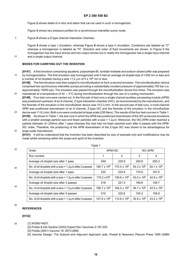
EP 2 380 558 B2
16
5
10
15
20
25
30
35
40
45
50
55
Figure 2 shows detail of a rotor and stator that can be used in such a homogenizer.
Figure 3 shows two pressure profiles for a synchronous intensifier pump mode.
Figure 4 shows a Z-type channel interaction chamber.
Figure 5 shows a type I circulation, whereas Figure 6 shows a type II circulation. Containers are labeled as "C"whereas a homogenizer is labeled as "H". Direction and order of fluid movements are shown. In Figure 6 thehomogenizer has two input arrows and two output arrows but in reality the homogenizer has a single input channeland a single output channel.
MODES FOR CARRYING OUT THE INVENTION
[0147] A first emulsion comprising squalene, polysorbate 80, sorbitan trioleate and sodium citrate buffer was preparedby homogenization. The first emulsion was homogenized until it had an average oil droplet size of 1200 nm or less anda number of oil droplets having a size >1.2 mm of 5 x 10⁹ /ml or less.[0148] The first emulsion was then subject to microfluidization to form a second emulsion. The microfluidization devicecomprised two synchronous intensifier pumps providing a substantially constant pressure of approximately 700 bar (i.e.approximately 10000 psi). The emulsion was passed through the microfluidization device five times. The emulsion wasmaintained at a temperature of 40 6 5°C during microfluidization through the use of a cooling mechanism.[0149] Four test runs were carried out. In the first pair of test runs a single channel auxiliary processing module (APM)was positioned upstream of an 8 channel, Z-type interaction chamber (IXC), as recommended by the manufacturer, andthe flowrate of the emulsion in the microfluidizer device was 10.2 L/min. In the second pair of test runs, a multi-channelAPM was positioned downstream of an 8 channel, Z-type IXC and the flowrate of the emulsion in the microfluidizerdevice was 11.6 L/min. Both runs were conducted at large scale (250 liters). The results of the four test runs are in Table 1.[0150] As shown in Table 1, the test runs in which the APM was positioned downstream of the IXC produced emulsionswith a smaller average particle size and fewer particles with a size > 1.2mm. Moreover, the IXC-APM order reached aparticle diameter of ≤200nm after 1 pass whereas this size had not been reached even after 4 passes with the APM-IXC order. Therefore, the positioning of the APM downstream of the Z-type IXC was shown to be advantageous forlarge-scale manufacture.[0151] It will be understood that the invention has been described by way of example only and modifications may bemade whilst remaining within the scope and spirit of the invention.
REFERENCES
[0152]
[1] WO90/14837.[2] Podda & Del Giudice (2003) Expert Rev Vaccines 2:197-203.[3] Podda (2001) Vaccine 19: 2673-2680.[4] Vaccine Design: The Subunit and Adjuvant Approach (eds. Powell & Newman) Plenum Press 1995 (ISBN
Table 1
Order APM-IXC IXC-APM
Run number 1 2 3 4
Average oil droplet size after 1 pass 249 220.9 200.8 200.3
No. of oil droplets with a size > 1.2mm after 2 passes 180.7 x 10⁶ 175.4 x 10⁶ 54.3 x 10⁶ 62,1 x 10⁶
Average oil droplet size after 1 pass 230 224.9 170.9 167.5
No. of oil droplets with a size > 1.2mm after 2 passes 170.2 x10⁶ 139.6 x 10⁶ 43.0 x 10⁶ 42.8 x 10⁶
Average oil droplet size after 3 passes 218 221.5 166.8 156.7
No. of oil droplets with a size > 1.2mm after 3 passes 166.7 x 10⁶ 164.3 x 10⁶ 36.7 x 10⁶ 42.5 x 10⁶
Average oil droplet size after 4 passes 215 222.6 154.3 156.8
No. of oil droplets with a size > 1.2mm after 4 passes 127.6 x 10⁶ 115.6 x 10⁶ 35.9 x 10⁶ 43.2 x 10⁶
EP 2 380 558 B2
17
5
10
15
20
25
30
35
40
45
50
55
0-306-44867-X).[5] Vaccine Adjuvants: Preparation Methods and Research Protocols (Volume 42 of Methods in Molecular Medicineseries). ISBN: 1-59259-083-7. Ed. O’Hagan.[6] New Generation Vaccines (eds. Levine et al.). 3rd edition, 2004. ISBN 0-8247-4071-8.[7] O’Hagan (2007) Expert Rev Vaccines 6(5):699-710.[8] EP-B-2029170[9] Baudner et al. (2009) Pharm Res. 26(6):1477-85.[10] Dupuis et al. (1999) Vaccine 18:434-9.[11] Dupuis et al. (2001) Eur J Immunol 31:2910-8.[12] Burke et al. (1994) J Infect Dis 170:1110-9.[13] Light Scattering from Polymer Solutions and Nanoparticle Dispersions (W. Schartl), 2007. ISBN:978-3-540-71950-2.[14] Jafari et al (2008) Food Hydrocolloids 22:1191-1202[15] WO90/04609.[16] US-4,618,533[17] US-6,193,077[18] US-6,495,050[19] Chen et al. (1999) Journal of Applied Polymer Science, 72:1699-1711.[20] US-4,413,074[21] US-4,432,875[22] US-4,340,482[23] US-4,473,474[24] US-4,473,475[25] US-4,673,504[26] EP-A-0221046.[27] US-4,943,374[28] US-6,071,406[29] US-4,705,753[30] US-5,178,765[31] US-6,495,043[32] US-6,039,872[33] US-5,277,812[34] US-5,531,893.[35] US-4,964,990[36] Wavhal & Fisher (2002) Journal of Polymer Science Part B: Polymer Physics 40:2473-88.[37] WO2006/044463.[38] Espinoza-Gómez et al. (2003) Revista de la Sociedad Quimica de México 47:53-57.[39] Lidgate et al (1992) Pharmaceutical Research 9(7):860-863.[40] US-2007/0014805.[41] WO2007/080308.[42] WO2007/052155.[43] WO2005/089837.[44] US 6,692,468.[45] WO00/07647.[46] WO99/17820.[47] US 5,971,953.[48] US 4,060,082.[49] EP-A-0520618.[50] WO98/01174.[51] Hoffmann et al. (2002) Vaccine 20:3165-3170.[52] Subbarao et al. (2003) Virology 305:192-200.[53] Liu et al. (2003) Virology 314:580-590.[54] Ozaki et al. (2004) J. Virol. 78:1851-1857.[55] Webby et al. (2004) Lancet 363:1099-1103.[56] WO97/37000.[57] Brands et al. (1999) Dev Biol Stand 98:93-100.[58] Halperin et al. (2002) Vaccine 20:1240-7.[59] Tree et al. (2001) Vaccine 19:3444-50.
EP 2 380 558 B2
18
5
10
15
20
25
30
35
40
45
50
55
[60] Kistner et al. (1998) Vaccine 16:960-8.[61] Kistner et al. (1999) Dev Biol Stand 98:101-110.[62] Bruhl et al. (2000) Vaccine 19:1149-58.[63] Pau et al. (2001) Vaccine 19:2716-21.[64] WO01/22992.[65] Hehme et al. (2004) Virus Res. 103(1-2):163-71.[66] Treanor et al. (1996) J Infect Dis 173:1467-70.[67] Keitel et al. (1996) Clin Diagn Lab Immunol 3:507-10.[68] Williamson et al. (2006) Infection and Immunity 74: 961-7.[69] Loukas et al. (2005) PLoS Med 2(10): e295.[70] EP-A-0139417.[71] Harper et al. (2004) Lancet 364(9447):1757-65.[72] J Toxicol Clin Toxicol (2001) 39:85-100.[73] Demicheli et al. (1998) Vaccine 16:880-884.[74] Stepanov et al. (1996) J Biotechnol 44:155-160.[75] Banzhoff (2000) Immunology Letters 71 :91-96.[76] WO02/097072.[77] Greenbaum et al. (2004) Vaccine 22:2566-77.[78] Zurbriggen et al. (2003) Expert Rev Vaccines 2:295-304.[79] Piascik (2003) J Am Pharm Assoc (Wash DC). 43:728-30.[80] Mann et al. (2004) Vaccine 22:2425-9.[81] Halperin et al. (1979) Am J Public Health 69:1247-50.[82] Herbert et al. (1979) J Infect Dis 140:234-8.[83] Chen et al. (2003) Vaccine 21:2830-6.[84] US 2006/251684.
Claims
1. A method for the manufacture of an oil-in-water emulsion comprising:
passing ≥ 50 liters of a first emulsion having a first average oil droplet size through a microfluidization deviceto form a second emulsion having a second average oil droplet size which is less than the first average oildroplet size; andfiltration of the second emulsion;wherein the microfluidization device comprises an interaction chamber which comprises a plurality of Z-typechannels and a back pressure chamber comprising at least one channel; andwherein the back pressure chamber is positioned downstream of the interaction chamber.
2. The method of claim 1, wherein the first emulsion is introduced into the interaction chamber at a first pressure andthe second emulsion exits the back pressure chamber at a second pressure which is lower than the first pressure;and wherein between 80 and 95 % of the pressure difference between the first and the second pressures is droppedacross the interaction chamber and 5 to 20 % of the pressure difference between the first and the second pressuresis dropped across the back pressure chamber.
3. The method of any one of the preceding claims, wherein the back pressure chamber comprises a plurality of channels.
4. The method of any one of the preceding claims, wherein the channel or channels of the back pressure chamberare Z-type channels.
5. The method of any of the preceding claims, comprising the step of formation of the first emulsion using a homogenizer.
6. The method of any one of the preceding claims, wherein the first average oil droplet size is 5000 nm or less.
7. The method according to any one of the preceding claims, wherein the number of oil droplets having a size of > 1.2mm in the first emulsion is 5 x 10¹¹ /ml or less.
8. The method of any one of the preceding claims, wherein the second average oil droplet size is 500 nm or less.
EP 2 380 558 B2
19
5
10
15
20
25
30
35
40
45
50
55
9. The method according to any one of the preceding claims, wherein the number of oil droplets having a size of > 1.2mm in the second emulsion is 5 x 10¹⁰ /ml or less.
10. A method for preparing a vaccine composition, comprising preparing an emulsion according to any one of claims 1to 9 and combining the emulsion with an antigen.
11. A method for preparing a vaccine kit comprising preparing an emulsion according to any one of claims 1 to 9 andpackaging the emulsion into a kit as a kit component together with an antigen component.
12. The method of claim 11, wherein the kit components are in separate vials; for example, wherein the vials are madefrom borosilicate glass.
13. The method of any of claims 10 to 12, wherein the emulsion is a bulk adjuvant and the method comprises extractingunit doses from the bulk adjuvant for packaging as kit components.
14. The method of any one of claims 10 to 13, wherein the antigen is an influenza virus antigen; for example, whereinthe combination of the emulsion and the antigen forms a vaccine composition and wherein the vaccine compositionincludes about 15mg, about 10mg, about 7.5mg, about 5mg, about 3.8mg, about 1,9mg, about 1.5mg of hemagglutininper influenza virus strain.
15. The method of any preceding claim, wherein: the interaction chamber has a plurality of fixed geometry channelsinto which the emulsion passes and in which the emulsion is accelerated under pressure to reduce the emulsion’soil droplet size and reduce the number of oil droplets having a size >1.2 mm; wherein channels in the interactionchamber include a plurality of substantially right-angled corners; and wherein the back pressure chamber has atleast one fixed geometry channel into which the emulsion passes.
Patentansprüche
1. Verfahren zum Herstellen einer Öl-in-Wasser-Emulsion, umfassend:
Passieren von ≥ 50 Litern einer ersten Emulsion, die eine erste mittlere Öltröpfchengröße aufweist, durch eineMikrofluidisierungsvorrichtung, um eine zweite Emulsion zu bilden, die eine zweite mittlere Öltröpfchengrößeaufweist, die kleiner als die erste mittlere Öltröpfchengröße ist; undFiltrieren der zweiten Emulsion;wobei die Mikrofluidisierungsvorrichtung eine Wechselwirkungskammer umfasst, die eine Vielzahl von Kanälenvom Z-Typ und eine Gegendruckkammer, umfassend wenigstens einen Kanal, umfasst; undwobei die Gegendruckkammer der Wechselwirkungskammer nachgeschaltet angeordnet ist.
2. Verfahren gemäß Anspruch 1, wobei die erste Emulsion mit einem ersten Druck in die Wechselwirkungskammereingeführt wird und die zweite Emulsion mit einem zweiten Druck, der kleiner als der erste Druck ist, aus derGegendruckkammer austritt; und wobei zwischen 80 und 95 % des Druckunterschieds zwischen dem ersten unddem zweiten Druck über die Wechselwirkungskammer abfallen und 5 bis 20 % des Druckunterschieds zwischendem ersten und dem zweiten Druck über die Gegendruckkammer abfallen.
3. Verfahren gemäß einem der vorstehenden Ansprüche, wobei die Gegendruckkammer eine Vielzahl von Kanälenumfasst.
4. Verfahren gemäß einem der vorstehenden Ansprüche, wobei der Kanal oder die Kanäle der GegendruckkammerKanäle vom Z-Typ sind.
5. Verfahren gemäß einem der vorstehenden Ansprüche, umfassend den Schritt der Herstellung der ersten Emulsionunter Verwendung eines Homogenisators.
6. Verfahren gemäß einem der vorstehenden Ansprüche, wobei die erste mittlere Öltröpfchengröße 5000 nm oderweniger beträgt.
7. Verfahren gemäß einem der vorstehenden Ansprüche, wobei die Anzahl der Öltröpfchen mit einer Größe von > 1,2
EP 2 380 558 B2
20
5
10
15
20
25
30
35
40
45
50
55
mm in der ersten Emulsion 5 x 10¹¹/ml oder weniger beträgt.
8. Verfahren gemäß einem der vorstehenden Ansprüche, wobei die zweite mittlere Öltröpfchengröße 500 nm oderweniger beträgt.
9. Verfahren gemäß einem der vorstehenden Ansprüche, wobei die Anzahl der Öltröpfchen mit einer Größe von > 1,2mm in der zweiten Emulsion 5 x 10¹⁰/ml oder weniger beträgt.
10. Verfahren zum Herstellen einer Impfstoffzusammensetzung, umfassend das Herstellen einer Emulsion gemäß ei-nem der Ansprüche 1 bis 9 und Kombinieren der Emulsion mit einem Antigen.
11. Verfahren zum Herstellen eines Impfstoff-Kits, umfassend das Herstellen einer Emulsion gemäß einem der Ansprü-che 1 bis 9 und Verpacken der Emulsion in ein Kit als Kit-Komponente zusammen mit einer Antigen-Komponente.
12. Verfahren gemäß Anspruch 11, wobei sich die Kit-Komponenten in getrennten Fläschchen befinden; beispielsweisewobei die Fläschchen aus Borsilicatglas hergestellt sind.
13. Verfahren gemäß einem der Ansprüche 10 bis 12, wobei die Emulsion ein Masse-Hilfsstoff ist und das Verfahrendas Extrahieren von Einheitsdosen aus dem Masse-Hilfsstoff zum Verpacken als Kit-Komponenten umfasst.
14. Verfahren gemäß einem der Ansprüche 10 bis 13, wobei das Antigen ein Influenzavirus-Antigen ist; beispielsweisewobei die Kombination der Emulsion und des Antigens eine Impfstoff-Zusammensetzung bildet und wobei dieImpfstoff-Zusammensetzung etwa 15 mg, etwa 10 mg, etwa 7,5 mg, etwa 5 mg, etwa 3,8 mg, etwa 1,9 mg, etwa 1,5mg an Hämagglutinin pro Influenzavirus-Stamm enthält.
15. Verfahren gemäß einem der vorstehenden Ansprüche, wobei die Wechselwirkungskammer eine Vielzahl von Ka-nälen mit unveränderlicher Geometrie aufweist, in welchen die Emulsion passiert und worin die Emulsion unterDruck beschleunigt wird, um die Öltröpfchengröße der Emulsion zu verringern und die Anzahl der Öltröpfchen miteiner Größe von > 1,2 mm zu verringern; wobei Kanäle in der Wechselwirkungskammer eine Vielzahl von im We-sentlichen rechtwinkligen Ecken umfassen; und wobei die Gegendruckkammer wenigstens einen Kanal mit unver-änderlicher Geometrie aufweist, in dem die Emulsion passiert.
Revendications
1. Procédé pour la fabrication d’une émulsion d’huile dans l’eau comprenant :
le passage de ≥ 50 litres d’une première émulsion ayant une première taille de gouttelette d’huile moyenne àtravers un dispositif de microfluidisation pour former une deuxième émulsion ayant une deuxième taille degouttelette d’huile moyenne qui est inférieure à la première taille de gouttelette d’huile moyenne ; etla filtration de la deuxième émulsion ;le dispositif de microfluidisation comprenant une chambre d’interaction qui comprend une pluralité de canauxde type Z et une chambre de contre-pression comprenant au moins un canal ; etla chambre de contre-pression étant positionnée en aval de la chambre d’interaction.
2. Procédé de la revendication 1, dans lequel la première émulsion est introduite dans la chambre d’interaction à unepremière pression et la deuxième émulsion sort de la chambre de contre-pression à une deuxième pression qui estinférieure à la première pression ; et dans lequel entre 80 et 95 % de la différence de pression entre les premièreet deuxième pressions est perdue à travers la chambre d’interaction et 5 à 20 % de la différence de pression entreles première et deuxième pressions est perdue à travers la chambre de contre-pression.
3. Procédé de l’une quelconque des revendications précédentes, dans lequel la chambre de contre-pression comprendune pluralité de canaux.
4. Procédé de l’une quelconque des revendications précédentes, dans lequel le canal ou les canaux de la chambrede contre-pression sont des canaux de type Z.
5. Procédé de l’une quelconque des revendications précédentes, comprenant l’étape de formation de la première
EP 2 380 558 B2
21
5
10
15
20
25
30
35
40
45
50
55
émulsion en utilisant un homogénéisateur.
6. Procédé de l’une quelconque des revendications précédentes, dans lequel la première taille de gouttelette d’huilemoyenne est de 5000 nm ou moins.
7. Procédé selon l’une quelconque des revendications précédentes , dans lequel le nombre de gouttelettes d’huileayant une taille > 1,2 mm dans la première émulsion est de 5 x 10¹¹/ml ou moins.
8. Procédé de l’une quelconque des revendications précédentes, dans lequel la deuxième taille de gouttelette d’huilemoyenne est de 500 nm ou moins.
9. Procédé selon l’une quelconque des revendications précédentes, dans lequel le nombre de gouttelettes d’huileayant une taille > 1,2 mm dans la deuxième émulsion est de 5 x 10¹⁰/ml ou moins.
10. Procédé pour préparer une composition de vaccin, comprenant la préparation d’une émulsion selon l’une quelconquedes revendications 1 à 9 et la combinaison de l’émulsion avec un antigène.
11. Procédé pour préparer un kit de vaccination comprenant la préparation d’une émulsion selon l’une quelconque desrevendications 1 à 9 et l’emballage de l’émulsion dans un kit en tant que composant de kit conjointement avec uncomposant d’antigène.
12. Procédé de la revendication 11, dans lequel les composants du kit sont dans des flacons séparés ; par exemple,dans lequel les flacons sont constitués de verre borosilicaté.
13. Procédé de l’une quelconque des revendications 10 à 12, dans lequel l’émulsion est un adjuvant en vrac et leprocédé comprend l’extraction de doses unitaires à partir de l’adjuvant en vrac pour conditionnement en tant quecomposants de kit.
14. Procédé de l’une quelconque des revendications 10 à 13, dans lequel l’antigène est un antigène du virus de lagrippe ; par exemple, dans lequel la combinaison de l’émulsion et de l’antigène forme une composition de vaccinet dans lequel la composition de vaccin comprend environ 15 mg, environ 10 mg, environ 7,5 mg, environ 5 mg,environ 3,8 mg, environ 1,9 mg, environ 1,5 mg d’hémagglutinine par souche de virus de la grippe.
15. Procédé de l’une quelconque des revendications précédentes, dans lequel : la chambre d’interaction a une pluralitéde canaux à géométrie fixe dans lesquels l’émulsion passe et dans lesquels l’émulsion est accélérée sous pressionpour réduire la taille de gouttelettes d’huile de l’émulsion et réduire le nombre de gouttelettes d’huile ayant une taille> 1,2 mm ; les canaux dans la chambre d’interaction comprenant une pluralité de coins sensiblement à angle droit ;et la chambre de contre-pression ayant au moins un canal à géométrie fixe dans lequel l’émulsion passe.
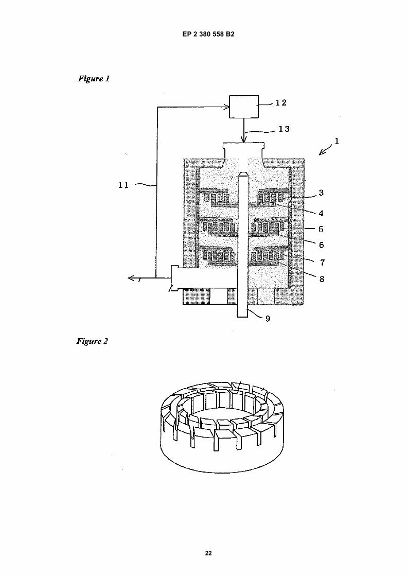
EP 2 380 558 B2
22
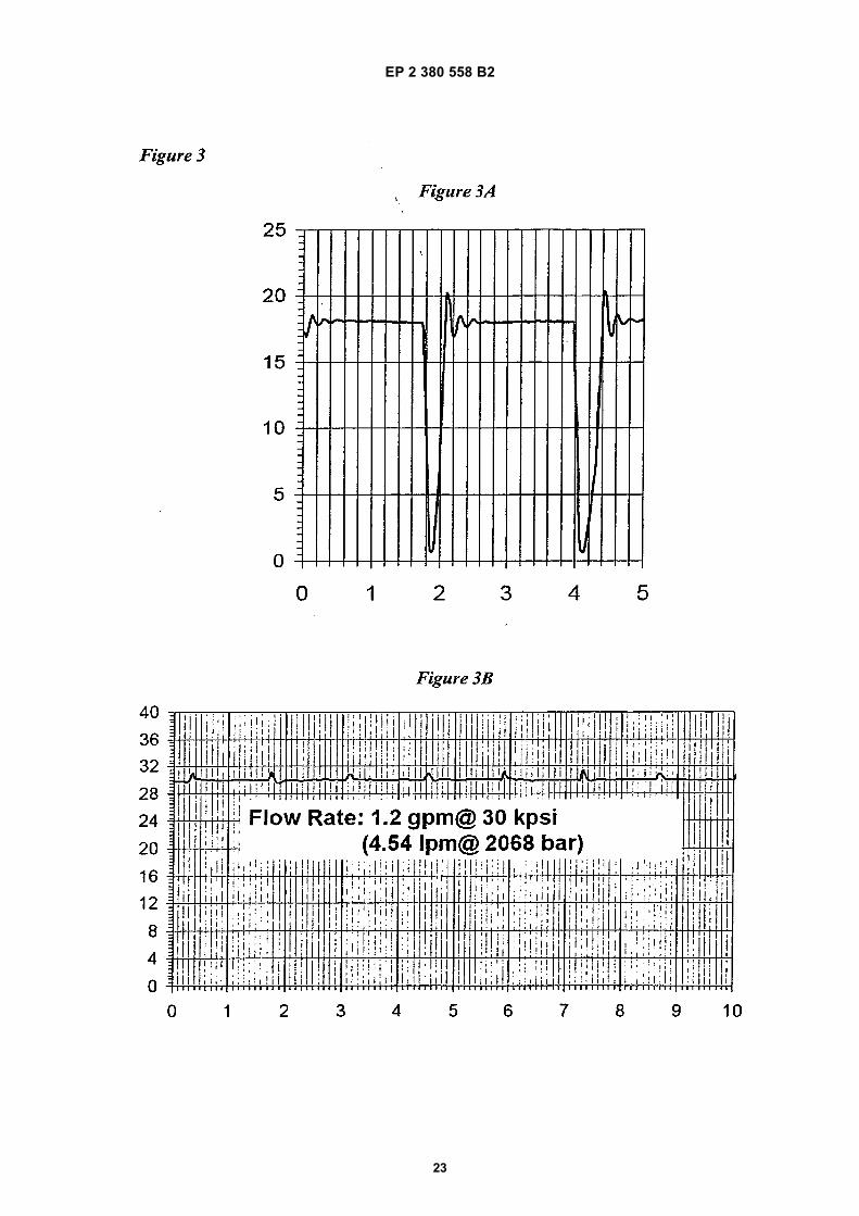
EP 2 380 558 B2
23
EP 2 380 558 B2
24
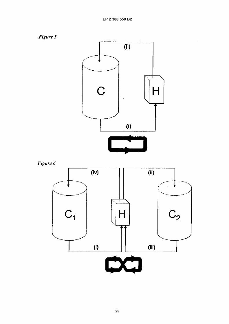
EP 2 380 558 B2
25
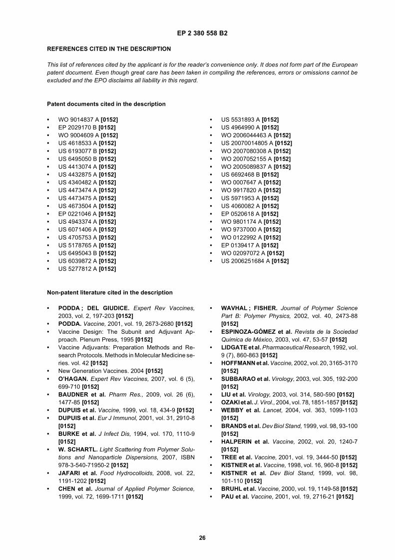
EP 2 380 558 B2
26
REFERENCES CITED IN THE DESCRIPTION
This list of references cited by the applicant is for the reader’s convenience only. It does not form part of the Europeanpatent document. Even though great care has been taken in compiling the references, errors or omissions cannot beexcluded and the EPO disclaims all liability in this regard.
Patent documents cited in the description
• WO 9014837 A [0152]• EP 2029170 B [0152]• WO 9004609 A [0152]• US 4618533 A [0152]• US 6193077 B [0152]• US 6495050 B [0152]• US 4413074 A [0152]• US 4432875 A [0152]• US 4340482 A [0152]• US 4473474 A [0152]• US 4473475 A [0152]• US 4673504 A [0152]• EP 0221046 A [0152]• US 4943374 A [0152]• US 6071406 A [0152]• US 4705753 A [0152]• US 5178765 A [0152]• US 6495043 B [0152]• US 6039872 A [0152]• US 5277812 A [0152]
• US 5531893 A [0152]• US 4964990 A [0152]• WO 2006044463 A [0152]• US 20070014805 A [0152]• WO 2007080308 A [0152]• WO 2007052155 A [0152]• WO 2005089837 A [0152]• US 6692468 B [0152]• WO 0007647 A [0152]• WO 9917820 A [0152]• US 5971953 A [0152]• US 4060082 A [0152]• EP 0520618 A [0152]• WO 9801174 A [0152]• WO 9737000 A [0152]• WO 0122992 A [0152]• EP 0139417 A [0152]• WO 02097072 A [0152]• US 2006251684 A [0152]
Non-patent literature cited in the description
• PODDA ; DEL GIUDICE. Expert Rev Vaccines,2003, vol. 2, 197-203 [0152]
• PODDA. Vaccine, 2001, vol. 19, 2673-2680 [0152]• Vaccine Design: The Subunit and Adjuvant Ap-
proach. Plenum Press, 1995 [0152]• Vaccine Adjuvants: Preparation Methods and Re-
search Protocols. Methods in Molecular Medicine se-ries. vol. 42 [0152]
• New Generation Vaccines. 2004 [0152]• O’HAGAN. Expert Rev Vaccines, 2007, vol. 6 (5),
699-710 [0152]• BAUDNER et al. Pharm Res., 2009, vol. 26 (6),
1477-85 [0152]• DUPUIS et al. Vaccine, 1999, vol. 18, 434-9 [0152]• DUPUIS et al. Eur J Immunol, 2001, vol. 31, 2910-8
[0152]• BURKE et al. J Infect Dis, 1994, vol. 170, 1110-9
[0152]• W. SCHARTL. Light Scattering from Polymer Solu-
tions and Nanoparticle Dispersions, 2007, ISBN978-3-540-71950-2 [0152]
• JAFARI et al. Food Hydrocolloids, 2008, vol. 22,1191-1202 [0152]
• CHEN et al. Journal of Applied Polymer Science,1999, vol. 72, 1699-1711 [0152]
• WAVHAL ; FISHER. Journal of Polymer SciencePart B: Polymer Physics, 2002, vol. 40, 2473-88[0152]
• ESPINOZA-GÓMEZ et al. Revista de la SociedadQuimica de México, 2003, vol. 47, 53-57 [0152]
• LIDGATE et al. Pharmaceutical Research, 1992, vol.9 (7), 860-863 [0152]
• HOFFMANN et al. Vaccine, 2002, vol. 20, 3165-3170[0152]
• SUBBARAO et al. Virology, 2003, vol. 305, 192-200[0152]
• LIU et al. Virology, 2003, vol. 314, 580-590 [0152]• OZAKI et al. J. Virol., 2004, vol. 78, 1851-1857 [0152]• WEBBY et al. Lancet, 2004, vol. 363, 1099-1103
[0152]• BRANDS et al. Dev Biol Stand, 1999, vol. 98, 93-100
[0152]• HALPERIN et al. Vaccine, 2002, vol. 20, 1240-7
[0152]• TREE et al. Vaccine, 2001, vol. 19, 3444-50 [0152]• KISTNER et al. Vaccine, 1998, vol. 16, 960-8 [0152]• KISTNER et al. Dev Biol Stand, 1999, vol. 98,
101-110 [0152]• BRUHL et al. Vaccine, 2000, vol. 19, 1149-58 [0152]• PAU et al. Vaccine, 2001, vol. 19, 2716-21 [0152]
EP 2 380 558 B2
27
• HEHME et al. Virus Res., 2004, vol. 103 (1-2), 163-71[0152]
• TREANOR et al. J Infect Dis, 1996, vol. 173, 1467-70[0152]
• KEITEL et al. Clin Diagn Lab Immunol, 1996, vol. 3,507-10 [0152]
• WILLIAMSON et al. Infection and Immunity, 2006,vol. 74, 961-7 [0152]
• LOUKAS et al. PLoS Med, 2005, vol. 2 (10), e295[0152]
• HARPER et al. Lancet, 2004, vol. 364 (9447),1757-65 [0152]
• J Toxicol Clin Toxicol, 2001, vol. 39, 85-100 [0152]• DEMICHELI et al. Vaccine, 1998, vol. 16, 880-884
[0152]
• STEPANOV et al. J Biotechnol, 1996, vol. 44,155-160 [0152]
• BANZHOFF. Immunology Letters, 2000, vol. 71,91-96 [0152]
• GREENBAUM et al. Vaccine, 2004, vol. 22, 2566-77[0152]
• ZURBRIGGEN et al. Expert Rev Vaccines, 2003, vol.2, 295-304 [0152]
• PIASCIK. J Am Pharm Assoc (Wash DC), 2003, vol.43, 728-30 [0152]
• MANN et al. Vaccine, 2004, vol. 22, 2425-9 [0152]• HALPERIN et al. Am J Public Health, 1979, vol. 69,
1247-50 [0152]• HERBERT et al. J Infect Dis, 1979, vol. 140, 234-8
[0152]• CHEN et al. Vaccine, 2003, vol. 21, 2830-6 [0152]