Embed Size (px)
DESCRIPTION
This project report is very valuable in learning the manufacturing process of a GT compressor blade on a 5-axis milling machine.
Citation preview

A PROJECT REPORT ON
MANUFACTURING OF A GT COMPRESSOR BLADE USING
5-AXIS MILLING METHOD AND COMPARISION OF THE
RESULTS WITH 3-AXIS MILLING METHOD
A report submitted for partial fulfillment of the B.Tech Degree in
Mechanical Engineering
Submitted by
G.Keerthana (10011P0305)
M.Vivekanand (10011P0311)
Rabbani Kausar (10011P0314)
Azaldeen Eltaher Mohamed (10011P0319)
Under the esteemed guidance of
Dr. M. Sreenivasa Rao
Professor
DEPARTMENT OF MECHANICAL ENGINEERING
JAWAHARLAL NEHRU TECHNOLOGICAL UNIVERSITY
KUKATPALLY, HYDERABAD – 500 085 (A.P.)
APRIL-2014
DEPARTMENT OF MECHANICAL ENGINEERING
JAWAHARLAL NEHRU TECHNOLOGICAL UNIVERSITY
COLLEGE OF ENGINEERING, HYDERABAD-500085

DEPARTMENT OF MECHANICAL ENGINEERING
JAWAHARLAL NEHRU TECHNOLOGICAL UNIVERSITY
COLLEGE OF ENGINEERING, HYDERABAD-500085
CERTIFICATE
This is to certify that the project report entitled “MANUFACTURING OF A GT
COMPRESSOR BLADE USING 5-AXIS MILLING METHOD AND
COMPARISION OF THE RESULTS WITH 3-AXIS MILLING METHOD”, has been
submitted by G.Keerthana (10011P0305), M.Vivekanand (10011P0311), Rabbani Kausar
(10011P0314), Azaldeen Eltaher Mohamed (10011P0319) in partial fulfillment of the
requirements for the award of degree of “BACHELOR OF TECHNOLOGY IN
MECHANICAL ENGINEERING” to the JNTUH COLLEGE OF ENGINEERING
HYDERABAD. This is a record of bonafide work carried out by them. The results of
investigations enclosed in this report have been verified and found to be satisfactory.
The results embodied in this report have not been submitted to any other university for
the award of any Degree or Diploma.
PROJECT GUIDE: HEAD OF THE DEPARTMENT:
Dr.M. Sreenivasa Rao Dr.B. Sudheer Prem Kumar
Professor (M.Tech., Ph.D. F.I.E (I))
Dept. of Mechanical Engineering Professor and Head
JNTUH College of Engineering Dept. of Mechanical Engineering
Hyderabad. JNTUH College of Engineering
Hyderabad.


i | P a g e
ACKNOWLEDGEMENT
This is an acknowledgement of the intensive drive and technical competence of many
individuals who have contributed to the success of our project.
I am immensely thankful to Mr. G. Madhavulu, Additional General Manager, TDL,
BHEL R&D, HYD for providing me the opportunity to carry out this project in such a reputed
organization.
I am very grateful to Mr. S. Srinu, Sr. Engineer, TDL, BHEL R&D, HYD for his
sagacious guidance and valuable suggestions during the course of our project.
My sincere thanks to Dr. B. Sudheer Prem Kumar, Head of Mechanical Engineering
Department, JNTUHCEH, Hyderabad, for granting us permission to carry out this project in
BHEL R&D, Hyderabad.
I would like to thank my internal guide Dr. M. Sreenivasa Rao, Professor, JNTUHCEH,
Hyderabad, for his encouragement and cooperation and all other staff members for the support
and motivation provided.
I like to extend my thanks to Mr. S. Biswas, General Manager, TDL, and members of
HRD for granting me permission for practical training through development of this project in
BHEL R&D, Hyderabad.
I like to express my gratitude to all members of TDL Dept. who were friendly and co-
operative
ii | P a g e
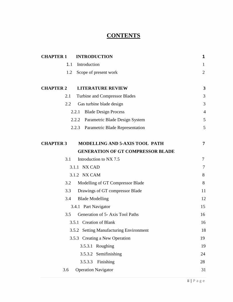
CONTENTS
CHAPTER 1 INTRODUCTION 1
1.1 Introduction 1
1.2 Scope of present work 2
CHAPTER 2 LITERATURE REVIEW 3
2.1 Turbine and Compressor Blades 3
2.2 Gas turbine blade design 3
2.2.1 Blade Design Process 4
2.2.2 Parametric Blade Design System 5
2.2.3 Parametric Blade Representation 5
CHAPTER 3 MODELLING AND 5-AXIS TOOL PATH 7
GENERATION OF GT COMPRESSOR BLADE
3.1 Introduction to NX 7.5 7
3.1.1 NX CAD 7
3.1.2 NX CAM 8
3.2 Modelling of GT Compressor Blade 8
3.3 Drawings of GT compressor Blade 11
3.4 Blade Modelling 12
3.4.1 Part Navigator 15
3.5 Generation of 5- Axis Tool Paths 16
3.5.1 Creation of Blank 16
3.5.2 Setting Manufacturing Environment 18
3.5.3 Creating a New Operation 19
3.5.3.1 Roughing 19
3.5.3.2 Semifinishing 24
3.5.3.3 Finishing 28
3.6 Operation Navigator 31

iii | P a g e
3.7 Simulation Compressor of Tool paths 31
3.7.1 Verify 31
CHAPTER 4 MANUFACTURING OF GT COMPRESSOR 34
BLADE
4.1 Blade Machining 34
4.2 Sturz milling method 34
4.2.1 Advantages of sturz milling 34
4.3 Machining the blade body 37
4.3.1 Roughing the Rombus 37
4.3.2 Semi finishing the blade 39
4.3.3 Finishing the blade 40
4.4 Post Processing 41
4.4.1 Post-processing sequence 42
4.4.1.1 NC Program 44
4.4.2 Post builder 46
4.5 Chiron 5-axis machine 47
4.5.1 Specifications 47
4.5.2 Components 48
4.5.3 Steps involved in machining the blade 49
CHAPTER 5 INSPECTION OF GT COMPRESSOR BLADE 53
USING 3D CMM
5.1 CMM Overview 53
5.1.1 Specifications 54
5.2 Camio V4.4 55
5.3 Inspection Procedure 56
5.3.1 Creating a Part Pragram 56
5.4 Inspection 57
5.5.1 Reporting 58
iv | P a g e
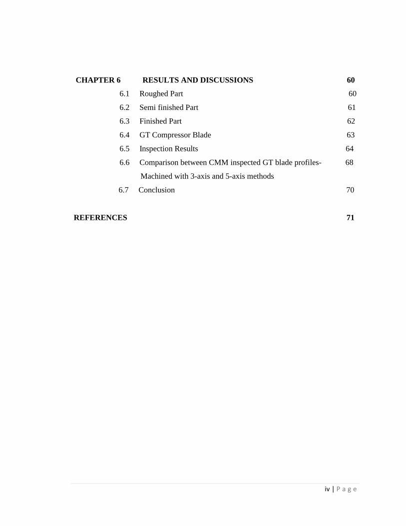
CHAPTER 6 RESULTS AND DISCUSSIONS 60
6.1 Roughed Part 60
6.2 Semi finished Part 61
6.3 Finished Part 62
6.4 GT Compressor Blade 63
6.5 Inspection Results 64
6.6 Comparison between CMM inspected GT blade profiles- 68
Machined with 3-axis and 5-axis methods
6.7 Conclusion 70
REFERENCES 71
REFERENCES 64
v | P a g e
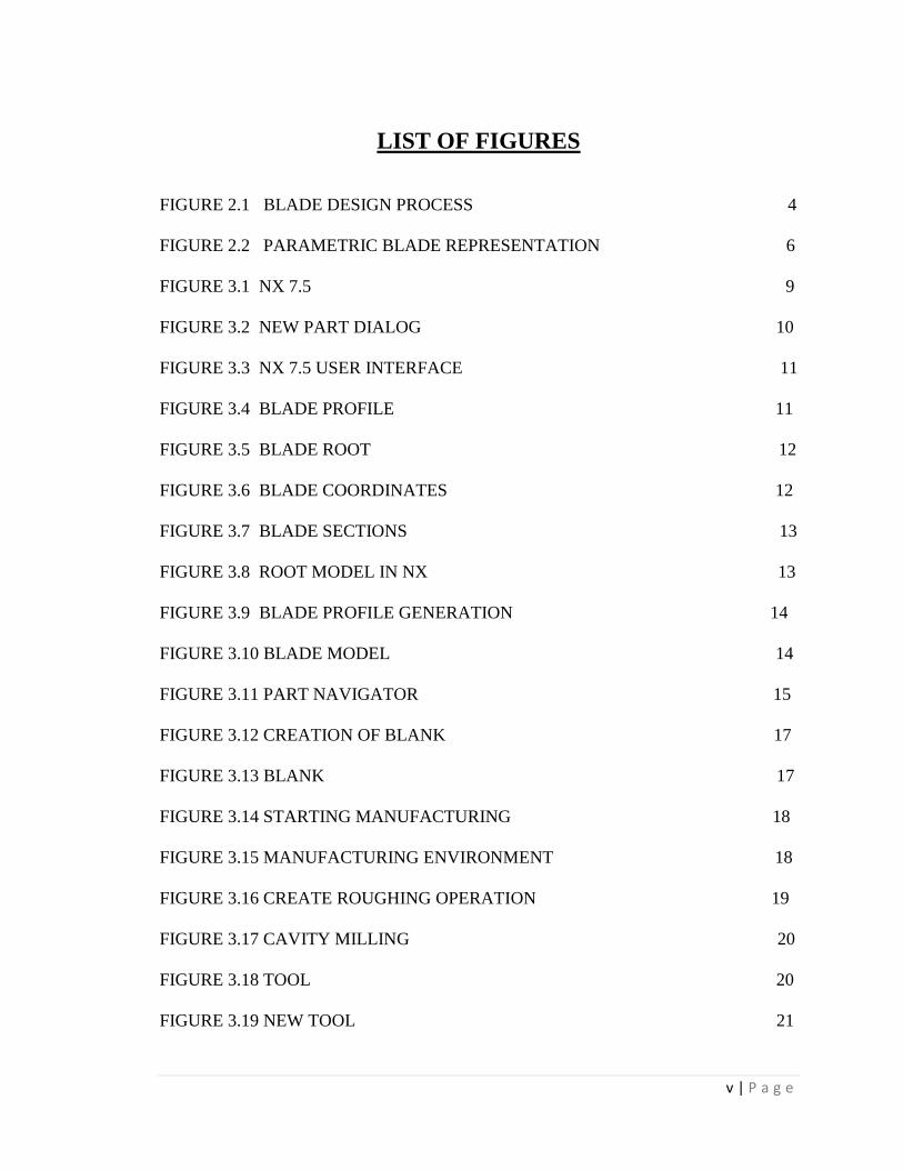
LIST OF FIGURES
FIGURE 2.1 BLADE DESIGN PROCESS 4
FIGURE 2.2 PARAMETRIC BLADE REPRESENTATION 6
FIGURE 3.1 NX 7.5 9
FIGURE 3.2 NEW PART DIALOG 10
FIGURE 3.3 NX 7.5 USER INTERFACE 11
FIGURE 3.4 BLADE PROFILE 11
FIGURE 3.5 BLADE ROOT 12
FIGURE 3.6 BLADE COORDINATES 12
FIGURE 3.7 BLADE SECTIONS 13
FIGURE 3.8 ROOT MODEL IN NX 13
FIGURE 3.9 BLADE PROFILE GENERATION 14
FIGURE 3.10 BLADE MODEL 14
FIGURE 3.11 PART NAVIGATOR 15
FIGURE 3.12 CREATION OF BLANK 17
FIGURE 3.13 BLANK 17
FIGURE 3.14 STARTING MANUFACTURING 18
FIGURE 3.15 MANUFACTURING ENVIRONMENT 18
FIGURE 3.16 CREATE ROUGHING OPERATION 19
FIGURE 3.17 CAVITY MILLING 20
FIGURE 3.18 TOOL 20
FIGURE 3.19 NEW TOOL 21

vi | P a g e
FIGURE 3.20 MILLING TOOL 5-PARAMETERS 21
FIGURE 3.21 PATH SETTINGS 22
FIGURE 3.22 GENERATING PROGRAM 22
FIGURE 3.23 TOOL PATH ON PRESSURE SIDE 23
FIGURE 3.24 TOOL PATH ON SUCTION SIDE 23
FIGURE 3.25 CREATE SEMI FINISHING OPERATION 24
FIGURE 3.26 FIXED CONTOUR 24
FIGURE 3.27 FLAT END MILL 25
FIGURE 3.28 TOOL PATH GENERATION 25
FIGURE 3.29 SEMI FINISHING TOOL PATH WITH BLANK 26
FIGURE 3.30 SEMI FINISHING TOOL PATH WITHOUT BLANK 26
FIGURE 3.31 SEMI FINISHING TOOL PATH ON SUCTION SIDE 27
FIGURE 3.32 SEMI FINISHING TOOL PATH ON SUCTION SIDE 27
WITHOUT BLANK
FIGURE 3.33 CREATING FINISHING OPERATION 28
FIGURE 3.34 FIXED CONTOUR 28
FIGURE 3.35 SURFACE AREA DRIVE METHOD 29
FIGURE 3.36 GENERATE FINISHING TOOL PATH 29
FIGURE 3.37 FINISHING TOOL PATH ON PRESSURE SIDE 30
FIGURE 3.39 FINISHING TOOL PATH ON SUCTION SIDE 30
FIGURE 3.39 OPERATION NAVIGATOR 31
FIGURE 3.40 VERIFY TOOL PATH 32
FIGURE 3.41 ROUGHING TOOL PATH VERIFICATION 32

vii | P a g e
FIGURE 3.42 SEMI FINISHING TOOL PATH VERIFICATION 33
FIGURE 3.43 FINISHING TOOL PATH VERIFICATION 33
FIGURE 4.1 COMPARISION OF STURZ 35
AND BALL END MILLING
FIGURE 4.2 ROUGHING THE RHOMBUS 37
FIGURE 4.3 MILLING STRATEGY 38
FIGURE 4.4 FEED DIRECTION 38
FIGURE 4.5 CUTTING PATHS 39
FIGURE 4.6 SEMI FINISHING THE BLADE 40
FIGURE 4.7 FINISHING THE BLADE 41
FIGURE 4.8 POST PROCESS 42
FIGURE 4.9 POST PROCESSED CODES 43
FIGURE 4.9 POST PROCESSOR 43
FIGURE 4.10 POST BUILDER 46
FIGURE 4.11 CHIRON 5-AXIS MACHINING CENTRE 47
FIGURE 4.12 MEASURING MCS BY OPTICAL EDGE FINDER 49
FIGURE 4.13 MACHINING PRESSURE SIDE 49
FIGURE 4.14 MACHINING SUCTION SIDE 50
FIGURE 4.15 SEMIFINISHING ON PRESSURE SIDE 51
FIGURE 4.16 SEMI FINISHING ON SUCTION SIDE 51
FIGURE 4.17 FINISHING ON PRESSURE SIDE 52
FIGURE 4.18 FINISHING ON SUCTION SIDE 52
FIGURE 5.1 LK ASCENT 3D COORDINATE MEASURING MACHINE 54

viii | P a g e
FIGURE 5.2 CAMIO STUDIO 55
FIGURE 5.3 OPEN INSPECION BOX 56
FIGURE 5.4 INSPECTION USING 3D CMM 57
FIGURE 5.5 SLICE SELECTION ON PROFILE 58
FIGURE 5.6 TOLERANCE SPECIFIED 59
FIGURE 5.7 DIGIGRAPH VLAUES AT 100MM DISTANCE 59
FROM OF PLANE BOTTOM
FIGURE 6.1 ROUGHED MACHINING ON PRESSURE SIDE 60
FIGURE 6.2 ROUGHED MACHINING ON SUCTION SIDE 61
FIGURE 6.3 SEMI FINISHED ON PRESSURE SIDE 61
FIGURE 6.4 SEMI FINISHED ON SUCTION SIDE 62
FIGURE 6.5 FINISHED ON PRESSURE SIDE 62
FIGURE 6.6 FINISHED BLADE 63
FIGURE 6.7 GT COMPRESSOR BLADE FRONT VIEW 63
FIGURE 6.8 GT COMPRESSOR BLADE 64
ix | P a g e
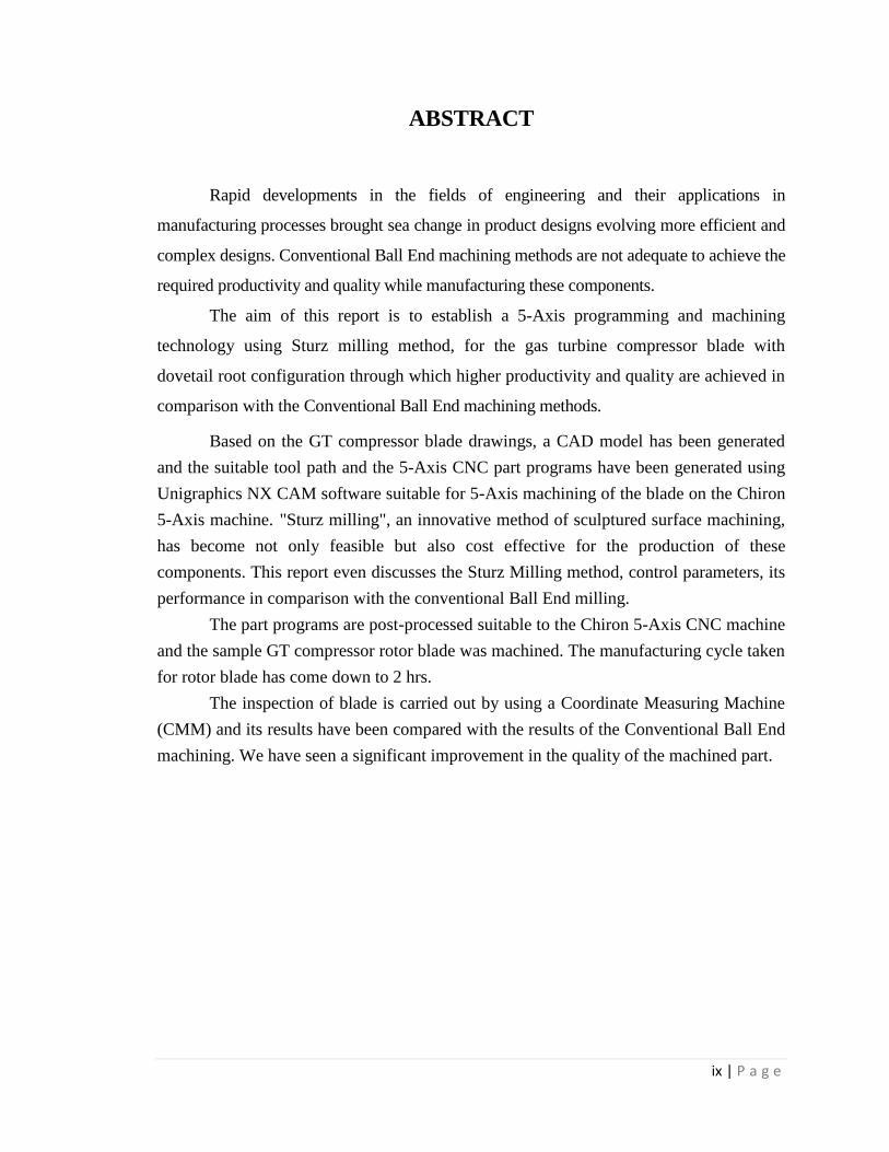
ABSTRACT
Rapid developments in the fields of engineering and their applications in
manufacturing processes brought sea change in product designs evolving more efficient and
complex designs. Conventional Ball End machining methods are not adequate to achieve the
required productivity and quality while manufacturing these components.
The aim of this report is to establish a 5-Axis programming and machining
technology using Sturz milling method, for the gas turbine compressor blade with
dovetail root configuration through which higher productivity and quality are achieved in
comparison with the Conventional Ball End machining methods.
Based on the GT compressor blade drawings, a CAD model has been generated
and the suitable tool path and the 5-Axis CNC part programs have been generated using
Unigraphics NX CAM software suitable for 5-Axis machining of the blade on the Chiron
5-Axis machine. "Sturz milling", an innovative method of sculptured surface machining,
has become not only feasible but also cost effective for the production of these
components. This report even discusses the Sturz Milling method, control parameters, its
performance in comparison with the conventional Ball End milling.
The part programs are post-processed suitable to the Chiron 5-Axis CNC machine
and the sample GT compressor rotor blade was machined. The manufacturing cycle taken
for rotor blade has come down to 2 hrs.
The inspection of blade is carried out by using a Coordinate Measuring Machine
(CMM) and its results have been compared with the results of the Conventional Ball End
machining. We have seen a significant improvement in the quality of the machined part.

1 | P a g e
CHAPTER 1
INTRODUCTION
1.1 Introduction
Traditionally, Turbo Machinery components, such as Compressor & Turbine
blades for steam & Gas Turbines, are machined in a series of different set-ups on CNC
Machines & copy milling machines. For CNC machining of these sculptured surfaces on
3-Axes CNC machines, Ball End Mill Cutters are inevitable for facilitating each
individually conceivable point to be machined, for desired accuracy.
While copy milling process becomes difficult to maintain, because of specific
requirements of copying masters, special fixtures and tooling for each type of component
separately, the conventional CNC machining with ball end cutters proves uneconomical
due to poor machining characteristics resulting from rubbing phenomenon. The use of
CNC Machines for turbine blade machining, thus, has been very poor so far, due to non-
availability of Multi Axes CNC machines and cost effective CNC programming
techniques for sculptured surfaces. However, with the right combination of Multi Spindle
5-Axes CNC Machining Centres, 5-Axes CNC programming capabilities and suitable
machining methods, the production cost and related lead times are significantly reduced.
Compared to 3-axis machining, 5-axis machining offers many advantages,
including the ability to manufacture complex parts with free form surface, better
material-removal rates, improved surface finish, reduced number of set-ups and thus
increased productivity .
The advantages of five-axis machining are significant, and include saving time
and money, among other things. But first, it’s important to know the design of a five-axis
machine and how it works.
There are two general application categories for five-axis machining: machining
complex 3D shapes and conventional machining of tilted surfaces. In both cases, the
difficulties related to creating five-axis programs have been simplified over the years.
Like any CNC machining center, a five-axis machine has three linear axes. The
layout for these axes will be the same as any three-axis VMC or HMC. For a vertical
viewed from the front, left/right is X, fore/aft is Y and up/down is Z.

2 | P a g e
Unlike three-axis machining centers, five-axis machining centers have two
additional rotary axes. For a VMC, the A axis is the rotary axis with a center line parallel
to the X axis. The rotary axis parallel to the Y axis is the B axis. (This is the most
common configuration for a vertical.)
Rotary axes can take one of two basic forms. One style incorporates rotary tables.
The first rotary table is mounted to the machine table and the second is mounted to the
first. The workpiece can be tilted in two directions.
With the second style of five-axis machining center, the rotary axes are
incorporated into the machine’s headstock and spindle. The spindle and cutting tool can
be tilted in each rotary axis. This method enables the workpiece to remain stationary,
which is beneficial for machining large parts. With either style, the axis conventions
remain the same. When viewing a vertical machine from the front (while X/Y is
left/right), workpiece/cutting tool tilt clockwise/counter clockwise is the B axis. When
the machine is veiwed from right side, workpiece/cutting tool tilt clockwise/counter
clockwise is the A axis.
1.2 Scope of present work
The manufacturing practices vary with different manufacturers mainly due to
The type of machine tools available.
The capability of programming the machines.
The complications in the design of the product like sharp corners , inaccessible
locations etc .
In the present work the blade of the first stage of a gas turbine compressor of 60 MV
capacity gas turbine is taken up for detailed CAM programming to enable reduced
manufacturing cycle time. The program is then loaded on a 5-Axis Chiron CNC machine
and used for producing a test blade to check and verify the correctness of the program.
The blade is then dimensionally checked down a CMM for dimensionally validity. The
CMM results are compared with that of the results when 3-Axis machining methods are
used.

3 | P a g e
CHAPTER 2
LITERATURE REVIEW
Prior to a discussion of the earlier literature, it is worthwhile to discuss briefly the
background information
2.1 TURBINE AND COMPRESSOR BLADES
The gas turbine is an internal combustion engine that uses air as the working
fluid. The engine extracts chemical energy from fuel and converts it to mechanical energy
using the gaseous energy of the working fluid (air) to drive the engine and propeller,
which, in turn, propel the airplane Gas turbine engines are, theoretically, extremely
simple. They have three parts
Compressor - Compresses the incoming air to high pressure
Combustion area - Burns the fuel and produces high-pressure, high -velocity gas
Turbine - Extracts the energy from the high-pressure, high -velocity gas flowing
from the combustion chamber
Turbine blades and compressor blades in flight and industrial turbine engines
require complicated, tight-tolerance "root form' profiles. Many types of blades also have
additional complex geometry like Z-notch forms, seals, platforms, and locking grooves.
These complex, tight-tolerance geometries are typically machined on blades by grinding.
All design properties both for the quasi-2-D profiles and the 3-D stacking line are
parameterized in a problem-adapted way to support the understanding of the aerodynamic
engineer. These parameters are then transformed into a fully CAD-compatible B-spline
representation. The geometry engine is completed with CFD-code integration, a blade
profile optimizing package, a parametric database and a correlation utility to find good
starting solutions for new design tasks based on existing proven technology.
2.2 GAS TURBINE BLADE DESIGN
The design process is fundamentally driven by physical properties of the
components, it’s weight, performance, stress behavior and life. All these properties are
estimated by various numerical simulation methods such as FEM, CFD and crack
propagation calculations. On the design side engineers are using more and more
advanced CAD system features. Originally the CAD was just a replacement of the
drawing board to get 2-D sketches out rapidly and with the chance to correct without
starting from scratch. Then the 3-D CAD systems came up where designers could create
and combine standard geometric entities such as cylinders, cubes, tetrahedral, sphere and
free-form surfaces. Then more and more emphasis was put onto processing the
4 | P a g e
topological information of a part or assembly. People started generating watertight solid
models in CAD
In order to process iterative changes and adjustments of a given part without
changing topology parametric CAD systems were developed. The idea of introducing
parametric into CAD revolutionized the design work and a new level of efficiency in
CAD work could be reached. Now with parametric 3-D solids as a standard, the original
work of step-by-step developing the CAD part and creating sketches, drawings and views
is more and more loosing its importance in the whole development cycle. Parameters of a
topological „master model“ can be treated outside the CAD world and can be subject to
optimizing processes or application of artificial intelligence, Neuronal networks, expert
and decision support systems. After a final optimized parametric configuration has been
detected, the parameter set is passed to the CAD and replaces the generic parameters of
the master model to create the final model.
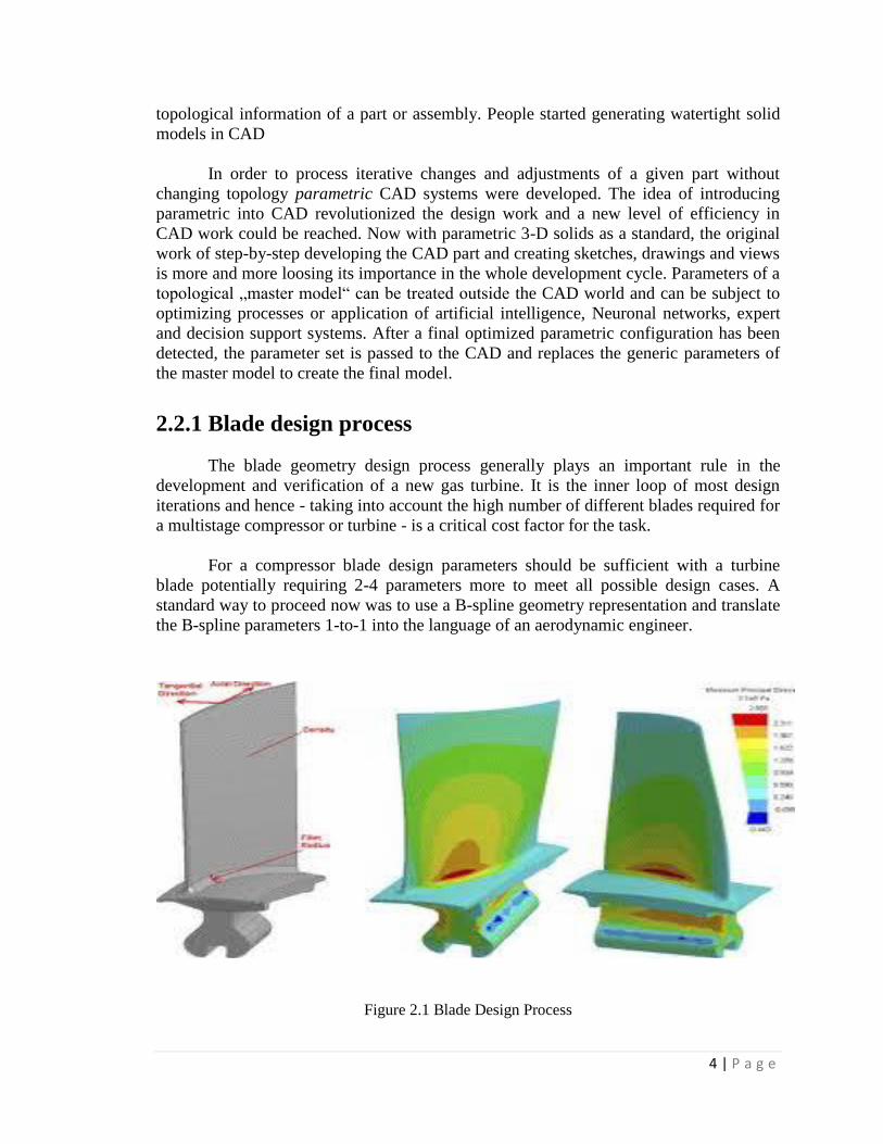
2.2.1 Blade design process
The blade geometry design process generally plays an important rule in the
development and verification of a new gas turbine. It is the inner loop of most design
iterations and hence - taking into account the high number of different blades required for
a multistage compressor or turbine - is a critical cost factor for the task.
For a compressor blade design parameters should be sufficient with a turbine
blade potentially requiring 2-4 parameters more to meet all possible design cases. A
standard way to proceed now was to use a B-spline geometry representation and translate
the B-spline parameters 1-to-1 into the language of an aerodynamic engineer.
Figure 2.1 Blade Design Process

5 | P a g e
Now, B-splines is the dialect that most CAD systems can understand. The only
task in-between is to transfer the parameters without loss into the 3-D solid CAD world.
Some extra work is required to do that, especially when the design works on real stream-
surfaces with varying radial height along the axis. The local coordinate systems on these
stream surfaces can be extremely dangerous, since they are not angle- or distance –
preserving. Depending on how you define them. So some integration and approximation
is necessary in the general case for the data exchange between CAD and aerodynamic
design system.
2.2.2 Parametric blade design system
The parametric blade design system is an engineering software package
designed at BRR to make the complex compressor & turbine geometry design process
better
faster
more reliable
Standardized.
The introduction of the parametric blade design system will influence other related
processes, such as FEM- and CFD-analysis and CAD-design. This has the potential to
simplify and improve the whole 3-D blade design process. The system consists of several
modules:
Auto Blading
Blade Profile Optimization
parametric Blade stacking
radial Blade smoothing and interpolation
parametric CAD interface
Parametric database.
2.2.3 Parametric blade representation
The blade profile parameters are the basis of the system. The blade
representation consists of two independent patches of higher order Bézier curves plus
leading & trailing edge geometry. Special attention is to be paid to the treatment of the
leading edge region. Currently both a circular leading edge and an elliptical leading edge
definition are used. Slope continuity is always maintained at the joint points.

6 | P a g e
Figure 2.2 Parametric blade representations

7 | P a g e
CHAPTER 3
MODELLING AND 5-AXIS TOOL PATH
GENERATION OF GAS TURBINE COMPRESSOR
BLADE
3.1 INTRODUCTION TO NX-7.5
NX is a premier 3D computer aided design suite. It allows you to model solid
components and assemblies, to perform engineering analyses such as mechanism
simulation and stress analysis, to create tool paths for computer-based manufacturing
processes and to perform numerous other engineering design activities in a single
software environment. Software suites like NX are referred to as product lifecycle
management (PLM) tools since they are generally integrated in the product design
process from start to finish.
Design Productivity - NX redefines CAD productivity with unique High
Definition 3D (HD3D)
CAE Productivity - NX redefines CAE productivity by integrating leading
geometry tools with powerful new analysis technology.
Manufacturing Productivity - NX redefines part manufacturing with new tools
that boost productivity including the introduction of two new applications that put
you in the context of a specific programming task. NX Turbo machinery Milling,
for programming complex blisks and impellers, produces expert results in half the
time.
NX CMM Inspection Programming – NX assists you by working automatically
off the intuitively presented PMI (Product and Manufacturing Information) model
data.
3.1.1 NX CAD
NX provides the freedom and accuracy designers need to explore shapes and
what-if styling in the modeling phase. By seamlessly combining surface and solid
modeling, as well as giving the designer access to traditional CAD tools, NX provides a
completely new kind of industrial design and styling solution. At the same time, the easy-
to-use toolbox promotes creativity and fosters innovation. These flexible tools, from
drag-and-drop templates to dynamic construction, enable fast, easy creation and
evaluation of design alternatives while providing real-time visual feedback. And there’s
no worry about changes or iterations. Associatively ensures that the design intent is
preserved every time a change occurs, without getting in the way of the designer.

8 | P a g e
NX is not like any of the traditional systems on the market. NX promotes the
philosophy that one modeling approach is not enough when it comes to complex design
tasks. For example, the designer may begin modeling by using standard parametric
design techniques that employ curve-driven geometry. Then, when creating contours and
integrating ergonomics, the designer can use free form techniques. Or the designer could
begin modeling without precise definitions, adding geometric constraints later.
Construction geometry and style details can be rapidly generated by the dynamic
mapping of 3D curves onto free form shapes. Or surfaces can be constructed using pre-
set combinations of section and guide curves, with the designer monitoring impact as it
occurs.
3.1.2 NX CAM
NX provides complete computer-aided manufacturing (CAM) software solutions
for machine tool programming, post processing and machining simulation. NX CAM’s
advanced functions in each of its modules can maximize returns on your investments in
the latest machine tool technology. Adopted across many industries, NX delivers proven
capabilities for manufacturing in the aerospace, automotive, medical device, mold and
die, and machinery industries.
NX CAM software provides a wide range of functionality, from simple NC
programming to high-speed and multi-axis machining, enabling you to address many
tasks with one system. The flexibility of NX CAM means that you can easily complete
the most demanding jobs.
3.2 MODELLING OF GT COMPRESSOR BLADE
To start NX, use the NX 7.5 shortcut under Start (or Windows button) → (All)
Programs →UGS NX 7.5. It may take a minute or so for NX to start the first time. Once
opened, you will be presented with the window shown in Figure below.

9 | P a g e
Figure 3.1 NX 7.5
To start modeling, you must first create a part file. NX part files use the extension
.prt for both components and assemblies of components. To create a new part, click the
New button to open the New dialog (Figure 2). For now, stay in the Model tab. Select
Model from the Templates list (the default) and set the Folder to a location on your S:
drive or desktop. The default location may be stored locally on the lab computer you are
using and might not be in your roaming profile (it might not be accessible on a different
computer). Once a folder has been selected, set the name of the part file. Click OK to
start modeling.

10 | P a g e
Figure 3.2 New part dialogs
Once the new file has been created, the NX modeling interface will open (Figure
3). Like most modern PLM tools, the interface for NX contains numerous icons, lists, text
prompts and other features that can be incredibly overwhelming. For now, we will focus
on the sketching tools, part navigator, viewer and menu.

11 | P a g e
Figure 3.3 NX 7.5 User Interface
3.3 DRAWINGS OF GT COMPRESSOR BLADES
Figure 3.4 Blade profile
12 | P a g e
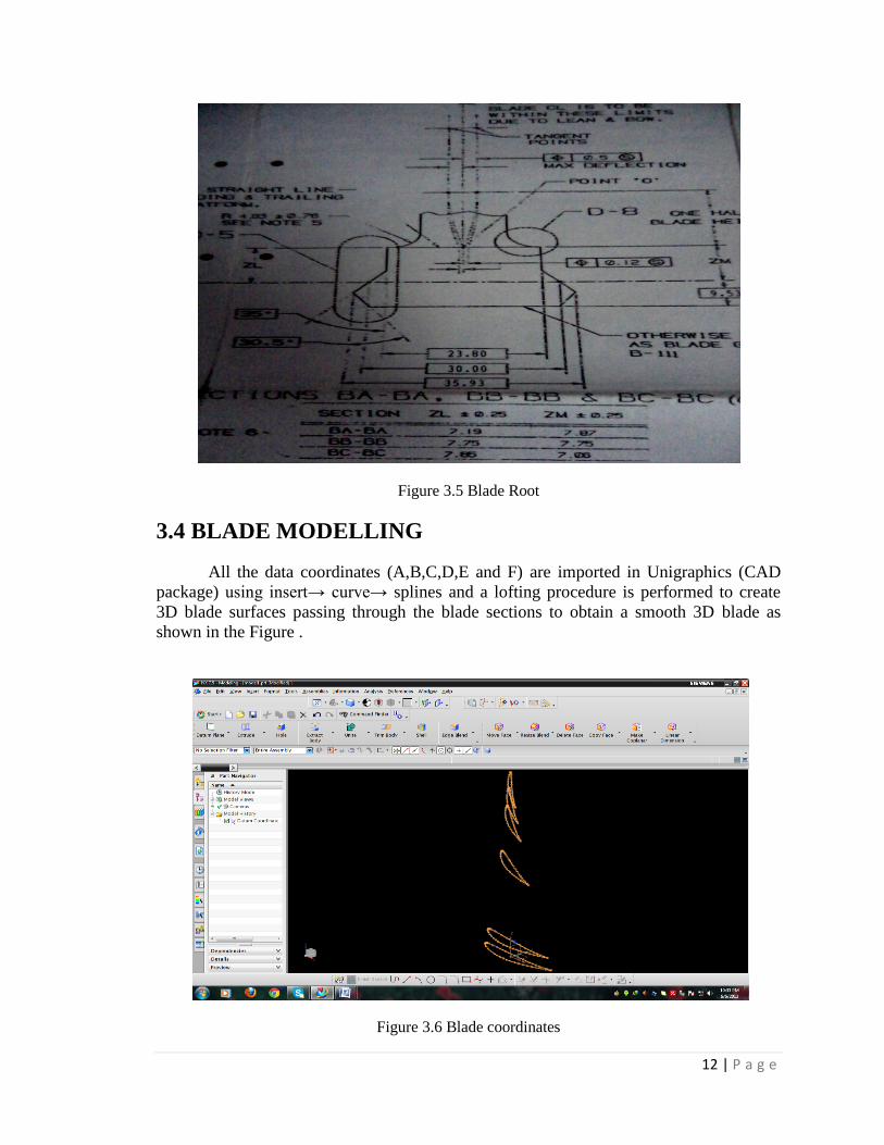
Figure 3.5 Blade Root
3.4 BLADE MODELLING
All the data coordinates (A,B,C,D,E and F) are imported in Unigraphics (CAD
package) using insert→ curve→ splines and a lofting procedure is performed to create
3D blade surfaces passing through the blade sections to obtain a smooth 3D blade as
shown in the Figure .
Figure 3.6 Blade coordinates

13 | P a g e
Figure 3.7 Blade Sections
Figure 3.8 Root model in NX
Using through curves profile of the blade will be generated using surfaces> through
curves. And root of the blade is modeled using blade root diagram and extruded.

14 | P a g e
Figure 3.9 Blade profile generation
Figure 3.10 Blade model

15 | P a g e
3.4.1 Part Navigator
Click on the Part Navigator icon, the second icon from the top on the Resource bar
The Part Navigator provides a visual representation of the parent-child
relationships of features in the work part in a separate window in a tree type format. It
shows all the primitives, entities used during modeling. It allows you to perform various
editing actions on those features. For example, you can use the Part Navigator to suppress
or unsuppressed the features or change their parameters or positioning dimensions.
Removing the green tick mark will ‘Suppress’ the feature. The software will give a
warning if the parent child relationship is broken by suppressing any particular feature.
The Part Navigator is available for all NX applications and not just for modeling.
However, you can only perform feature-editing operations when you are in the Modeling
module. Editing a feature in the Part Navigator will automatically update the model.
Figure 3.11 Part navigator

16 | P a g e
3.5 GENERATION OF 5-AXIS TOOL PATHS
NX-CAM offers a wide range of strategies to make efficient 5 axis programming
and include wide and flexible range of tool path generation strategies and post
processing tools to support the full range of 5-axis machine tools.
It supports a range of methods for defining precisely controlled tool paths on
complex surfaces, with effective collision and gouge checking.
It enables fast, accurate roughing and finishing of complex parts in turbo
machinery industry.
Curvature matching is new technology that constantly varies the tool angle
relative to the stock surface to maximize the tool contact area. This allows you to
remove more material with fewer passes for a given tool diameter.
Templates allow to customize the user interface and specify machining Setups
which can include machine tools, cutting tools, machining methods, shared
geometry, and sequences of operations.
The Operation Navigator allows to view and manage relationships between
operations, geometry, machining methods, and tools
NX CAM machine tool simulation provides 5-axis programmers with the
essential tools for proving out their machine motion. It offers full 3D motion of
the machine tool within its limits, driven by the post processed G-code.
3.5.1 Creation of a Blank
After completing the modeling, you should decide upon the raw material shape
and size that needs to be loaded on the machine for the actual machining. This data has to
be input in NX-7.5. This can be achieved in two ways. The first method is by creating or
importing the model of the raw material as a separate solid in the same file and assigning
that solid as the Blank. The second method is by letting the software decide the extreme
dimensions of the designed part and some offset values if wanted. The later method
allows a quick way of assigning the raw size details but it can only be used for prismatic
shapes.
Open the file ‘blade-model’
Click on START → MODELING
Create a block covering the blade as shown below

17 | P a g e
Figure 3.12 Creation of blank
Figure 3.13 Blank

18 | P a g e
3.5.2 Setting Machining Environment
Now we are set to get into the Manufacturing module.
Select START → MANUFACTURING
A window will pop up asking for the Machining Environment Setup. There are
many different customized CAM sessions available for different machining operations.
Here, we are only interested in the Milling operation.
Figure 3.14 Starting Manufacturing
For CAM Session Configuration, select cam_general and for CAM Setup, select
mill_contour. This window pops up when you start the Manufacturing Application
Click INITIALIZE.
Figure 3.15 Manufacturing Environment

19 | P a g e
3.5.3 Creating a new operation
The Manufacturing setup is now ready for us to work further with Programming
Strategies. There are many different strategies involved in programming and it takes
practice to know which one is the most efficient. Here, the basic guidelines are given for
the most widely and frequently used strategies. The chapter will also cover important
parameters that are to be set for the programs to function properly.
3.5.3.1 Roughing
First Roughing will be on pressure side
Click on the Create Operation icon in the toolbar as shown
The Create Operation window will pop up.
Make sure the Type of Operation is mill_contour.
Click on the CAVITY_MILL icon at the top left as shown in the figure.
Figure 3.16 Create roughing operation
The program parameters window with CAVITY_MILL in the title bar will pop
up. On this window, you can set all the parameters for the program. A brief introduction
on every important parameter and terminology will be given as we go through the
sequence.
20 | P a g e
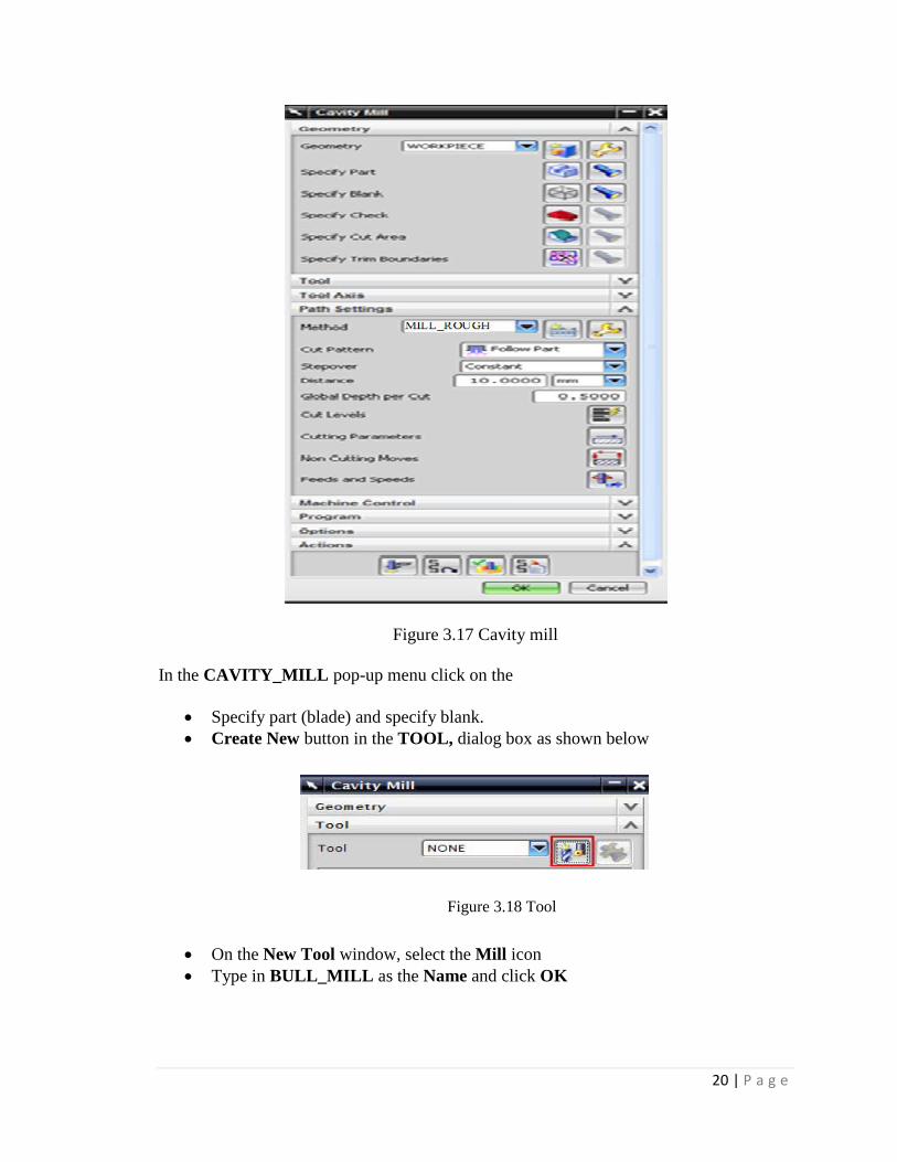
Figure 3.17 Cavity mill
In the CAVITY_MILL pop-up menu click on the
Specify part (blade) and specify blank.
Create New button in the TOOL, dialog box as shown below
Figure 3.18 Tool
On the New Tool window, select the Mill icon
Type in BULL_MILL as the Name and click OK

21 | P a g e
Figure 3.19 New tool
Change diameter to 20 and Lower radius to 6.
Specify vector for tool axis
Click Ok
Figure 3.20 Milling Tool-5 Parameters

22 | P a g e
There are different options in which the tool can move. The following is a description of
each.
Figure 3.21 Path settings
Now we are done entering all the parameters required for the roughing program. It is time
to generate the program.
Click on the Generate icon at the bottom of the window.
Figure 3.22 Generating program
You can now observe the software slicing the model into depths of cuts and creating tool-
path at every level. You can find on the model cyan, blue, red and yellow lines as shown
in the figure.

23 | P a g e
Figure 3.23 Tool path on pressure side
For roughing on suction side repeat the same procedure just change the vector axis
Figure 3.24 Tool path on suction side
24 | P a g e
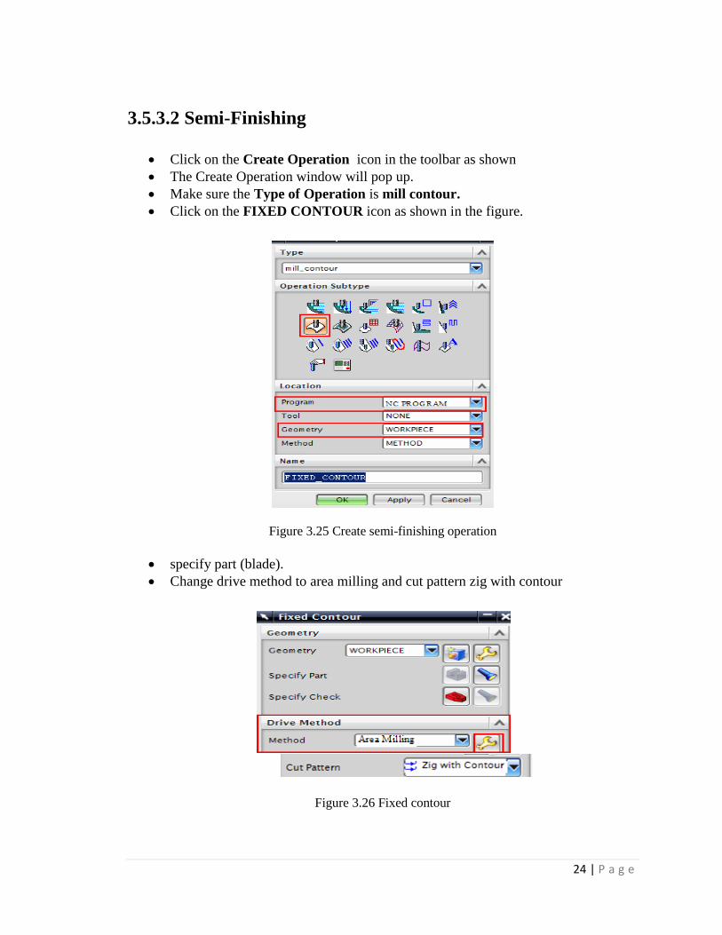
3.5.3.2 Semi-Finishing
Click on the Create Operation icon in the toolbar as shown
The Create Operation window will pop up.
Make sure the Type of Operation is mill contour.
Click on the FIXED CONTOUR icon as shown in the figure.
Figure 3.25 Create semi-finishing operation
specify part (blade).
Change drive method to area milling and cut pattern zig with contour
Figure 3.26 Fixed contour

25 | P a g e
Create New button in the TOOL, dialog box
On the New Tool window, select the Mill icon
Type in FLAT_END_MILL as the Name and click OK
Figure 3.27 Flat end mill
Change diameter to 12.
Specify vector for tool axis
Click Ok
In path settings method to Mill_ Semi_finishing..
click generate icon as shown below.
Figure 3.28 tool path generation
26 | P a g e
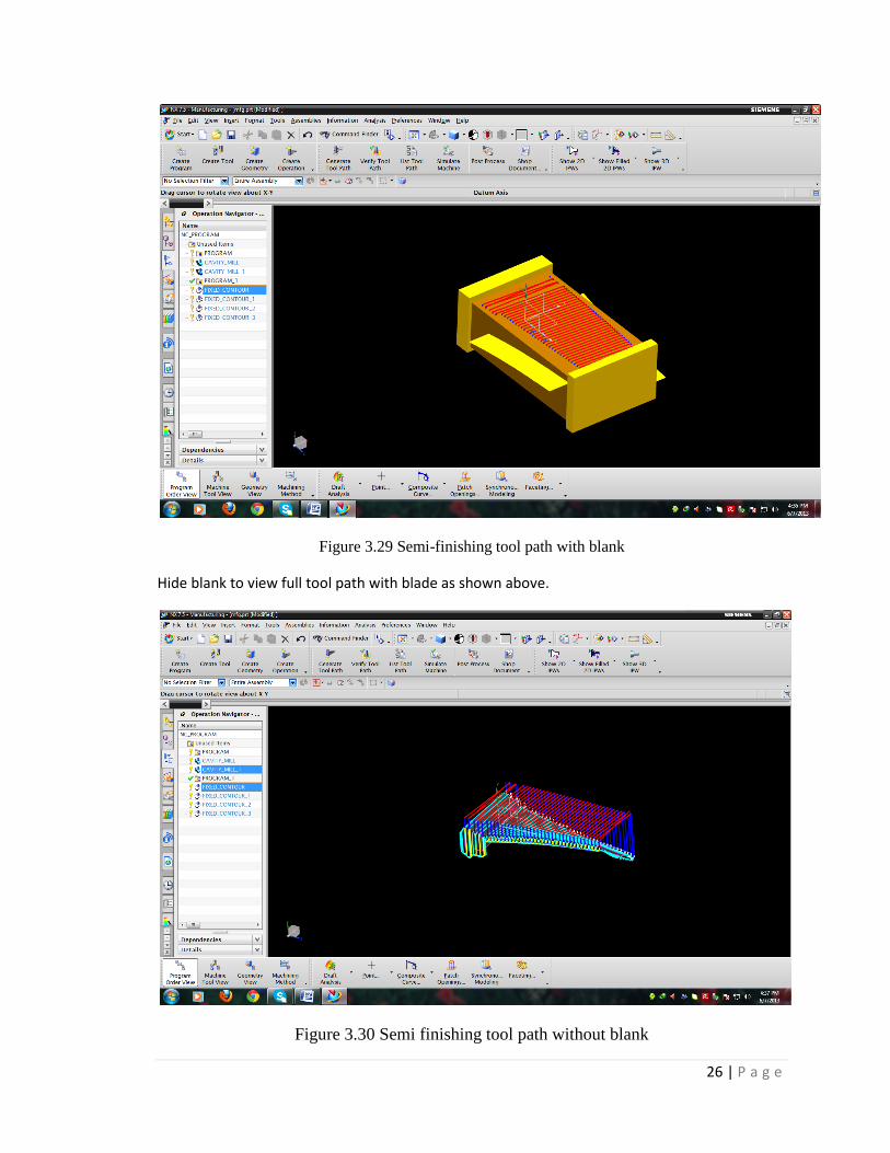
Figure 3.29 Semi-finishing tool path with blank
Hide blank to view full tool path with blade as shown above.
Figure 3.30 Semi finishing tool path without blank

27 | P a g e
Figure 3.31 Semi finishing tool path on suction side
Figure 3.32 Semi finishing tool path on suction side without blank
28 | P a g e
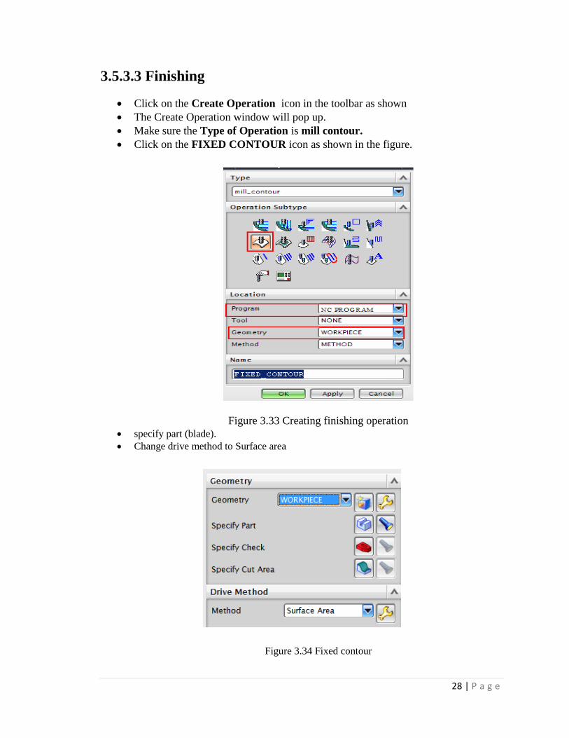
3.5.3.3 Finishing
Click on the Create Operation icon in the toolbar as shown
The Create Operation window will pop up.
Make sure the Type of Operation is mill contour.
Click on the FIXED CONTOUR icon as shown in the figure.
Figure 3.33 Creating finishing operation
specify part (blade).
Change drive method to Surface area
Figure 3.34 Fixed contour

29 | P a g e
Specify drive geometry and other parameters as shown in figure below.
Figure 3.35 Surface area drive method
Create New button in the TOOL, dialog box
On the New Tool window, select the Mill icon
Type in BALL_MILL as the Name and click OK.
select tool diameter to 12 and specify vector for tool axis.
In path settings method to Mill_ finish.
click generate icon as shown below.
Figure 3.36 Generate finishing tool path

30 | P a g e
Figure 3.37 Finishing tool path on pressure side
Figure 3.38 Finishing tool path on suction side

31 | P a g e
3.6 OPERATION NAVIGATOR
As soon as you get into the Manufacturing environment, you will notice many
changes in the main screen such as new icons that are displayed.
Click on the OPERATION NAVIGATOR tab on the right on the RESOURCE BAR.
The Operation Navigator gives information about the programs created and
corresponding information about the cutters, methods, and strategies.
Figure 3.39 Operation navigator
3.7 SIMULATION COMPRESSOR OF TOOL PATHS
It is very important to check the programs you have created. This prevents any
improper and dangerous motions from being made in the cutting path. It is possible that
wrong parameters and settings will be given that cause costly damages to the work piece.
To avoid such mistakes, NX7.5 and other CAM software provide Tool-path verification
and a simulation.
3.7.1 Verify:
The Tool-Path verification can be used to view the cutter motion in the entire
program. You can observe how the tool is engaged and how it retracts after cutting. It
also shows the actual material being removed through graphical simulation. You can also
view the specific zone of interest by moving the line of the program.
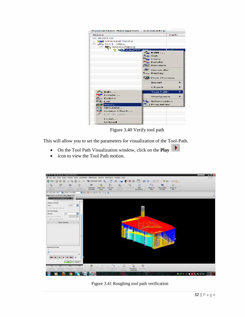
Right-click on the program in the Operation Navigator and choose TOOL
PATH →VERIFY or click on the Verify Tool Path button in the toolbar
32 | P a g e
Figure 3.40 Verify tool path
This will allow you to set the parameters for visualization of the Tool-Path.
On the Tool Path Visualization window, click on the Play
icon to view the Tool Path motion.
Figure 3.41 Roughing tool path verification
33 | P a g e
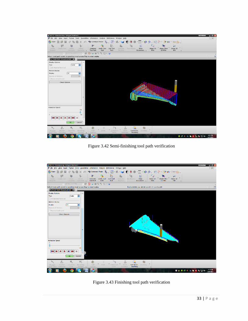
Figure 3.42 Semi-finishing tool path verification
Figure 3.43 Finishing tool path verification

34 | P a g e
CHAPTER 4
MANUFACTURING OF GT COMPRESSOR BLADE
4.1 BLADE MACHINING
Blades of many different sizes and geometries are utilized in gas turbines, and can
perform different functions within the turbine. Some are stationary blades, while others
are rotating, and it is usually the rotating blades which present the greater machining
challenges due to their tougher materials and more complex designs. The stationary
blades, also called vanes, have simpler designs and are primarily used to direct the
airflow. Hence they are usually regarded as being easier to machine than rotating blades,
although the quality of their manufacture is still critical for turbine efficiency.
4.2 STURZ MILLING METHOD:
The key to the cost effectiveness of 5-axis CNC Machining for turbine blades, is
“Sturz” milling. “Sturz” is a German term, which refers to a milling path, where the flat end
mill cutter is inclined in the forward direction of motion. Under this method the contact
point of tool & job surface lies at the periphery unlike at the dead centre in case of
conventional ball end machining. This ensures better metal cutting performance because of
the larger effective radius and constant cutting speeds.
Though, "Sturz" milling technique, is not very new to manufacturing field, it's
application in CNC machining of turbine blades opens a new chapter in turbo machinery
manufacturing industry.
4.2.1 ADVANTAGES OF "STURZ" MILLING
The use of "Sturz" milling offers a set of distinct advantages solving many problems
faced in the traditional Ball End Milling and Disk Cutter Copy Machining of Turbine
blades.
Small scallop heights with large Cross feed: The furrow produced by “Sturz" milling
path has a wide shallow elliptical cross-sectional form instead if a semi-circle in the case
of Ball end Milling. At any given cross feed, these paths overlap and produce scallop
heights much smaller than those of disk-form cutters or ball end mill cutters of suitable
sizes. This means for a given scallop height, a blade can be machined in less number of
passes, which results in reduced machining time.

35 | P a g e
Improved Tool Life and better Surface Finish: In the Ball end Milling method, The
cutting speed at the cutter centre (dead centre) is zero while, it is maximum at the
periphery. This leads to a dominant rubbing action resulting lesser tool life and poor
surface finish. The constant cutting speed at the periphery of the tool, in case of Sturz
milling, improves the tool life and surface finish dramatically.
The use of standard Flat End milling cutters: In contrast to ball end cutters, which are
special formed cutters, the use of off-the-shelf standard flat end mill cutters as in case of
Sturz milling is highly economical. In case of flat end mill cutters the re-grinding costs
and the use of carbide inserts further improves the economic gains.
Reduced vibration and deflection problems: Unlike ball end milling, Sturz milling
results in reduced vibration and deflection because of the fact that the forces induced are
less in magnitude and not directed towards the job surface. This allows larger feed rates
and metals removal rates yielding higher productivity.
Figure 4.1 Comparison of sturz and ball end milling

36 | P a g e
Figure 4.1 Comparison of sturz and ball end milling
37 | P a g e
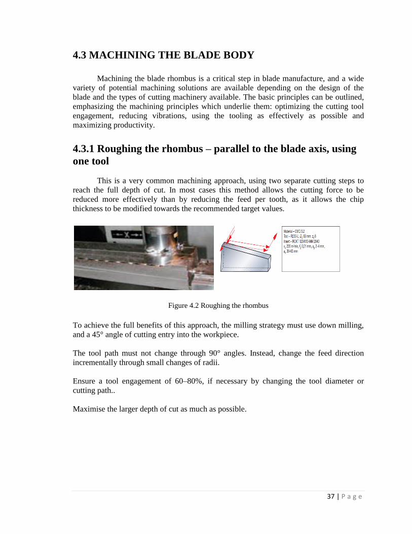
4.3 MACHINING THE BLADE BODY
Machining the blade rhombus is a critical step in blade manufacture, and a wide
variety of potential machining solutions are available depending on the design of the
blade and the types of cutting machinery available. The basic principles can be outlined,
emphasizing the machining principles which underlie them: optimizing the cutting tool
engagement, reducing vibrations, using the tooling as effectively as possible and
maximizing productivity.
4.3.1 Roughing the rhombus – parallel to the blade axis, using
one tool
This is a very common machining approach, using two separate cutting steps to
reach the full depth of cut. In most cases this method allows the cutting force to be
reduced more effectively than by reducing the feed per tooth, as it allows the chip
thickness to be modified towards the recommended target values.
Figure 4.2 Roughing the rhombus
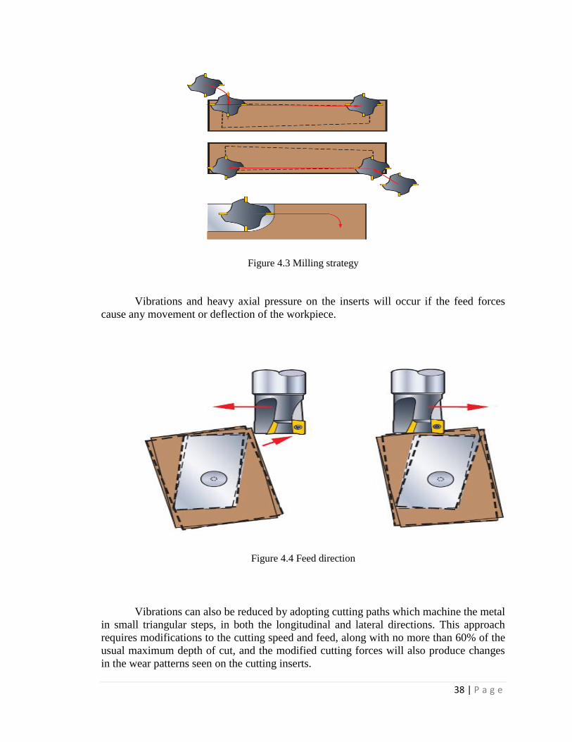
To achieve the full benefits of this approach, the milling strategy must use down milling,
and a 45° angle of cutting entry into the workpiece.
The tool path must not change through 90° angles. Instead, change the feed direction
incrementally through small changes of radii.
Ensure a tool engagement of 60–80%, if necessary by changing the tool diameter or
cutting path..
Maximise the larger depth of cut as much as possible.
38 | P a g e
Figure 4.3 Milling strategy
Vibrations and heavy axial pressure on the inserts will occur if the feed forces
cause any movement or deflection of the workpiece.
Figure 4.4 Feed direction
Vibrations can also be reduced by adopting cutting paths which machine the metal
in small triangular steps, in both the longitudinal and lateral directions. This approach
requires modifications to the cutting speed and feed, along with no more than 60% of the
usual maximum depth of cut, and the modified cutting forces will also produce changes
in the wear patterns seen on the cutting inserts.

39 | P a g e
Figure 4.5 Cutting paths
4.3.2 Semi-finishing the blade
The semi finishing operation requires a 5-axis milling operation, and will directly
influence the surface quality of the final finished blade. Therefore the aim should always
be to achieve a very regular, uniform level of residual material if necessary, through two
separate semi finishing operations. Normally this operation is done by turn milling.
The recommended tool is an end mill with indexable inserts, such as the CoroMill
390, or a round insert milling cutter such as CoroMill 300. The choice of tool will depend
on the profile of the blade and its size.
A variety of tool paths can be employed. One common technique, especially when
machining large cast blades, is to use a feed direction along the blade length, but other
possibilities are shown in the diagram. For example, the blade can be shaped by milling
across the blade, either using several passes in one direction with a rapid return
movement between passes, or in a single continuous helical cut around the blade.

40 | P a g e
Figure 4.6 Semi finishing the blade
4.3.3 Finishing the blade
Finishing the blade is probably the most difficult 5-axis machining operation, but
its success will greatly depend on the quality of the other machining steps carried out
previously.
The most suitable tool depends on the type and size of the blade, and also on the
spindle speed and the feed available in the machining centre. The capabilities of the
machines employed can often be the limiting
factors.
In general, it is possible to use solid carbide endmills like CoroMill Plura 216.24,
or endmills with indexable inserts, such as the CoroMill 390 with inserts R390 11T3
31EPM 1025).
The tool diameters vary, e.g. between 10–20 mm.
The principal problems when finishing are vibrations, and the quality of the pre-
finished surfaces. Using tools with a smaller radius, r, or using a different number of
inserts in the cutting head can help combat vibrations, in line with the recommendations
given in Coromant publications During the cutting process the tool follows a helical path
around the blade, a path controlled by a specialised CAD-CAM system.To achieve the

41 | P a g e
best surface quality and structure, the tool has to maintain a constant normangle at each
point on the surface, and always in a downmilling manner.
Figure 4.7 Finishing the blade
4.4 POST PROCESSING
The primary use of the Manufacturing application is to generate tool paths in
order to manufacture parts. Generally, we cannot just send an unmodified tool path file to
a machine and start cutting because there are many different types of machines. Each
type of machine has unique hardware capabilities, requirements and control systems. For
instance, it can have a vertical or a horizontal spindle; it can cut while moving several
axes simultaneously, etc. The controller accepts a tool path file and directs tool motion
and other machine activity (such as turning the coolant or air on and off).
Naturally, just as each type of machine has unique hardware characteristics;
controllers also differ in software characteristics. For instance, most controllers require
that the instruction for turning the coolant on be given in a particular code. Some
controllers also restrict the number of M codes that are allowed in one line of output. This
information is not in the initial NX7.5 NX tool path.
`Therefore, the tool path must be modified to suit the unique parameters of each
different machine/controller combination. The modification is called post processing. The
result is a post processed tool path.
Tool paths consist of GOTO points and other information that controls the
movement of a tool with respect to the part. This unmodified tool path usually needs to
be specifically formatted for a particular machine tool/controller combination.
Differences are based on character formats, tool change requirements, type of machine,
number of controlled axis of motion, etc.
The tool path must be formatted to match the unique characteristics of the
machine tool/controller combination. The procedure of modifying this generic tool path

42 | P a g e
to a form that can be understood and used by the machine tool controller is called post
processing.
Two elements are required for post processing. They are:
• Tool path - A NX internal tool path
• Post processor - this is a program that reads, converts and reformats tool path
information for a particular machine tool/controller combination.
4.4.1 Post-Processing sequence
Click on a program in the Operation Navigator that you want to post process.
Click TOOLS → OPERATION NAVIGATOR → OUTPUT → NX
POSTPROCESSING
Select the MILL_5_AXIS machine and enter a location for the file
Select OK
This will create the post-processed file for the desired machine. It can be seen that the
block numbers with G and M codes concerning the Machine controller type.
Figure 4.8 post process

43 | P a g e
Figure 4.9 Post processed codes
5-axis machining requires machine-control (NC) post processing to convert the
cutter-location (CL) data that define the tool path data with a CAM system into the NC
data that the machine can read.
NC Post processing is the process of translating machining instructions from a
CAM system into NC program code for a unique machine.
The tool path data is reformatted by the postprocessor for the machine.
Figure 4.10 postprocessor

44 | P a g e
4.4.1.1 NC PROGRAM
============================================================
Information listing created by: CIMAR07
Date : 7/4/2014 3:41:35 PM
Current work part : C:\Documents and Settings\cimar07\Desktop\mech
project\fr6-rot02.prt
Node name : cimar07
============================================================
%
N0010 G40 G17 G94 G90 G70
N0020 G91 G28 Z0.0
:0030 T00 M06
N0040 G0 G90 X3.4646 Y-2.9724 A270. B0.0 S0 M03
N0050 G43 Z1.8765 H00
N0060 Z1.3915
N0070 G1 Z1.2734 F9.8 M08
N0080 X2.874
N0090 Y-7.5
N0100 G2 X2.6772 Y-7.6969 I-.1969 J0.0
N0110 G1 X-2.6772
N0120 G2 X-2.874 Y-7.5 I0.0 J.1969
N0130 G1 Y1.5551
N0140 G2 X-2.6772 Y1.752 I.1969 J0.0
N0150 G1 X2.6772
N0160 G2 X2.874 Y1.5551 I0.0 J-.1969

45 | P a g e
N0170 G1 Y-2.9724
N0180 X2.6772
N0190 Y-7.5
N0200 X-2.6772
N0210 Y1.5551
N0220 X2.6772
N0230 Y-2.9724
N0240 X2.4803
N0250 Y-7.3031
N0260 X-2.4803
N0270 Y1.3583
N0280 X2.4803
N0290 Y-2.9724
N0300 X2.2835
N0310 Y-7.1063
N0320 X-2.2835
N0330 Y1.1614
N0340 X2.2835
N0350 Y-2.9724
N0360 X2.0866
N0370 Y-6.9094
N0380 X-2.0866
N0390 Y.9646
N0400 X2.0866
N0410 Y-2.9724
46 | P a g e
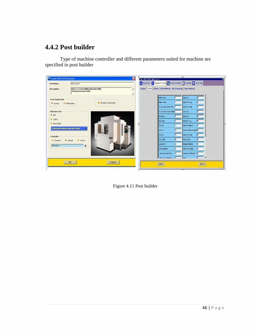
4.4.2 Post builder
Type of machine controller and different parameters suited for machine are
specified in post builder
Figure 4.11 Post builder

47 | P a g e
4.5 CHIRON 5-AXIS MACHINE
Figure 4.12 chiron 5-axis machining centre
4.5.1 SPECIFICATIONS
MANUFACTURER: Chiron, Germany
Controller : Sinumeric 840D
Travel:
X-axis 800 mm
Y-axis 630 mm
Z-axis 550 mm
Spindle AC-motor17,0 kW at 100 % 47,2 kW at 5 % for mainspindle
Spindle speed range: 20 - 12.000 rpm - max.180 Nm
COLUMN MOVING MACHINING CENTRE with swing setup Linear-guide ways
with long-term grease lubrication
Digital direct drives AC-servo motors for x-, y- and z-axes with
direct absolute path Glass scales measuring system over pressured in all axes rapid
traverse in all axes 60 m/min. acceleration 0.5 m/s2
210 bar Hydraulic unit incl. valves for supply and clamping circuit for clamping of
faceplate and counter bearing complete with hydraulic connection
48 | P a g e
Scratch Band Chip conveyor and PF 50 / KFA 900 Coolant Equipment: tank
capacity 900 l, pump capacity from 100 l/min at 2,1 bar up to 250 l/min at 1,8 bar high
pressure pump capacity 20 l/min at 30 bar high pressure circuit with filtration via paper
bond filter, filtration
50 Rm nominal. Twin filter in the high pressure circuit for the protection of the machine.
No of tools : 24
No of axes: 5 axes continuous.
Max job weight: 300Kg.
4.5.2 COMPONENTS
NC swivel head
The NC swivel head with hydraulic clamping and water-cooled motor spindle has a
swivelling range of ± 110° and distinguishes itself by its exceptionally high rigidity,
overload capacity and speed.
CNC CONTROL
The MILL series can be delivered with a Siemens, Fanuc or Heidenhain CNC
control. A CNC machine controller runs G-code and M code programs and provides the
user interface between the machine and the operator. The controller is capable of full 5-
axes simultaneous motion.
AUTOMATIC TOOL CHANGE USING THE PICK-UP METHOD,
Starting from 1.5 s (24 / 40 / 60 tool places) The tool changing system is a quick,
failure-proof pick-up system. It takes only 1.5 s to change tools. The chain magazine with
24 (optionally 40) tool places is designed for tool holders with ISO 40 or HSK-A 63 and
separated from the working area. Tools with a diameter of up to 125 mm and length of up
to 280 mm can be used.
TOOL MAGAZINE
Tools are made available from the background magazine (92 or 165 ISO / CAT
40 or HSK-A 63 tool places) during machining. The intelligent tool management chain
serves as storage for frequently used tools. If more tools are required, a background
magazine can also be used during the machining operation. A total of 92 tools can be
used. These tools are assigned to specific magazine places with fixed codes and
are immediately brought back to their respective places after use.

49 | P a g e
4.5.3 STEPS INVOLVED IN MACHINING THE BLADE
Blank Selection and Measuring MCS by Optical Edge Finder
Figure 4.13 Measuring MCS by optical edge finder
Machining of Pressure Side using bull nose cutter of diameter 20mm and lower radius 6
mm
Figure 4.14 Machining pressure side

50 | P a g e
Machining of Suction Side using bull nose cutter of diameter 20mm and lower radius 6
mm
Figure 4.15 Machining suction side
Semi finishing operation done by flat end mill cutter of diameter 12mm on pressure side

51 | P a g e
Figure 4.16 Semi finishing on pressure side
Semi finish operation done by flat end mill cutter of diameter 12mm on suction side
Figure 4.17 Semi finish on suction side
The finishing of blade on pressure and also chamfer of the root is done by ball nose cutter
of 12mm dia.
52 | P a g e
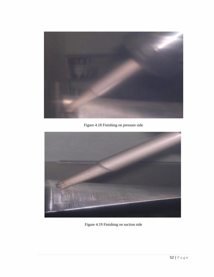
Figure 4.18 Finishing on pressure side
Figure 4.19 Finishing on suction side

53 | P a g e
CHAPTER 5
INSPECTION OF GT COMPRESSOR BLADE USING
3D-CMM
5.1 CMM OVERVIEW
LK CMMs are available in various configurations based on overhead beam or
horizontal spindle designs. The CMM axes move on a cushion of air supplied by air
bearings and are assembled around a granite work surface. The granite work surface has a
number of drilled and tapped holes to allow for part location. The axes of the CMM allow
measurements to be made on a part or work piece in a Cartesian co-ordinate system.
Points are taken with a probe mounted on the Z axis spindle. The axes can be moved
manually with the joysticks on the hand box, or through CNC to facilitate probing and the
taking of points. Point data is supplied to a computer via the reading of digital encoders
on optical scales. There is one optical scale for each axis of the CMM. During correct
operation the CMM ‘knows’ the precise location of the probe as points are taken. The
axes are driven by motors acting either via belts or on drive bars. The CMM is connected
through an electronic control unit to a computer workstation. Output devices for the
computer comprise a VDU and printer and provision is also made for connection to a
network.

54 | P a g e
Figure 5.1 LK Ascent – 3D Coordinate Measuring Machine
5.1.1 Specifications
Name: 3D CNC CMM
Manufacturer: LK (Metris), UK
Model: Ascent
Type: Bridge
Range: 8.7.6
Controller: ACT
Application Software: Camio 4.4
55 | P a g e
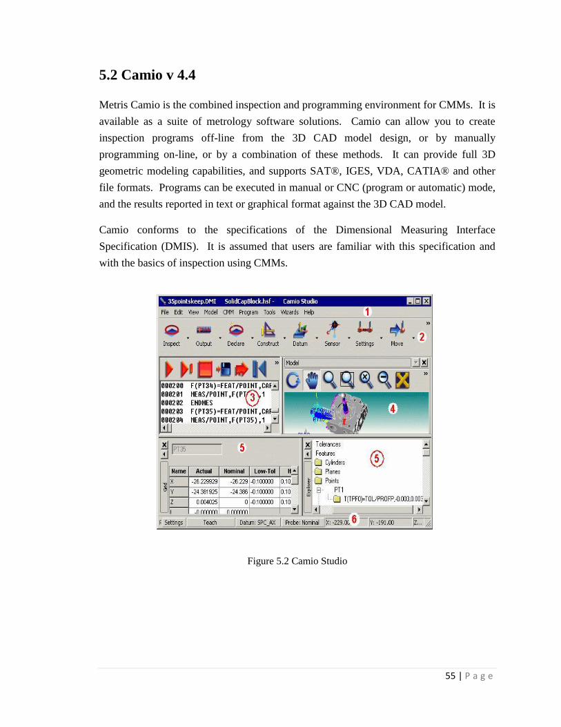
5.2 Camio v 4.4
Metris Camio is the combined inspection and programming environment for CMMs. It is
available as a suite of metrology software solutions. Camio can allow you to create
inspection programs off-line from the 3D CAD model design, or by manually
programming on-line, or by a combination of these methods. It can provide full 3D
geometric modeling capabilities, and supports SAT®, IGES, VDA, CATIA® and other
file formats. Programs can be executed in manual or CNC (program or automatic) mode,
and the results reported in text or graphical format against the 3D CAD model.
Camio conforms to the specifications of the Dimensional Measuring Interface
Specification (DMIS). It is assumed that users are familiar with this specification and
with the basics of inspection using CMMs.
Figure 5.2 Camio Studio

56 | P a g e
5.3 INSPECTION PROCEDURE
The manufactured test blade and the heat treated test blades are inspected for
deviations using the 3D Coordinate Measuring Machine.
5.3.1 Creating a Part Program
When you create a new program, a template of DMIS commands is inserted in
your program. If Camio cannot find the DMIS template file that contains these
commands, it will create one for you.
To create a new part program, select New Program from the File menu. If you
wish to use any default tolerances you have previously defined using the Tolerance
dialog box, check the Use default tolerances box in the New Inspection dialog box (click
the Advanced button). Otherwise, any required tolerances must be defined in the part
program.
Check input, output, DTA, XML files in Output options.
Open the iges model file in Model options.
Check the CSV option in Reporting option.
Figure 5.3 Open Inspection Box
57 | P a g e
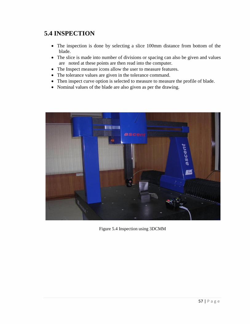
5.4 INSPECTION
The inspection is done by selecting a slice 100mm distance from bottom of the
blade.
The slice is made into number of divisions or spacing can also be given and values
are noted at these points are then read into the computer.
The Inspect measure icons allow the user to measure features.
The tolerance values are given in the tolerance command.
Then inspect curve option is selected to measure to measure the profile of blade.
Nominal values of the blade are also given as per the drawing.
Figure 5.4 Inspection using 3DCMM

58 | P a g e
Figure 5.5 Slice selection on profile
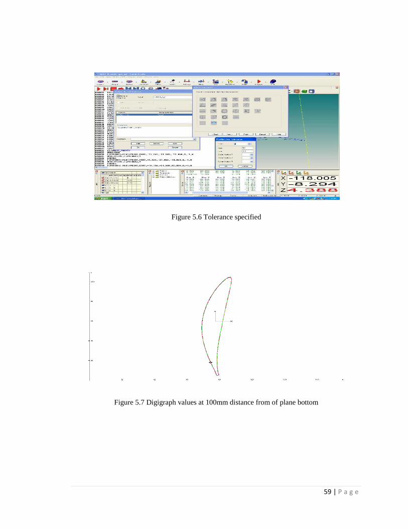
5.4.1 Reporting
LK Studio Reporting allows to output text and graphics reports from inspection
data. A report will be created by selecting LK Studio Reporting option.
The report can be obtained either in notepad or in excel sheets. Graphical reporting
can be obtained using digigraph.
The results give the deviations in blade by considering the actual, nominal and
tolerance values.
59 | P a g e
Figure 5.6 Tolerance specified
Figure 5.7 Digigraph values at 100mm distance from of plane bottom
60 | P a g e
CHAPTER 6
RESULTS AND DISCUSSIONS
The results of machining at different stages, like Roughing, semi finishing, and
finishing are discussed below. Also discussed are the results of inspection of specimen
blade.
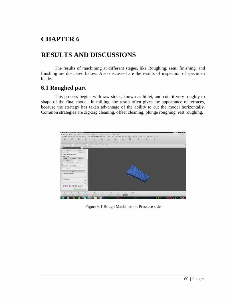
6.1 Roughed part
This process begins with raw stock, known as billet, and cuts it very roughly to
shape of the final model. In milling, the result often gives the appearance of terraces,
because the strategy has taken advantage of the ability to cut the model horizontally.
Common strategies are zig-zag cleaning, offset cleaning, plunge roughing, rest roughing.
Figure 6.1 Rough Machined on Pressure side

61 | P a g e
Figure 6.2 Rough Machined on suction side
6.2 Semi-finished part
This process begins with a roughed part that unevenly approximates the model
and cuts to within a fixed offset distance from the model. The semi-finishing pass must
leave a small amount of material so the tool can cut accurately while finishing, but not so
little that the tool and material deflect instead of shearing.
Figure 6.3 Semi finished on pressure side
62 | P a g e
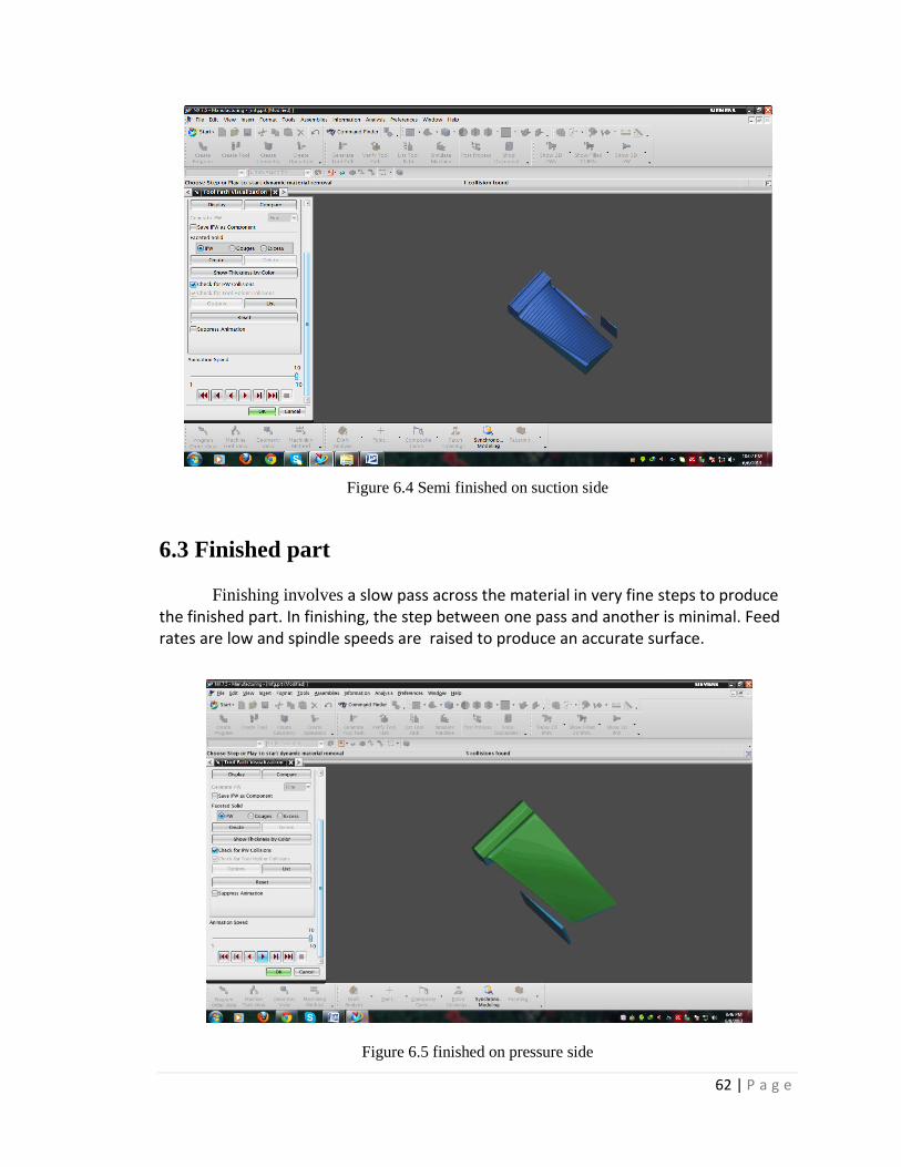
Figure 6.4 Semi finished on suction side
6.3 Finished part
Finishing involves a slow pass across the material in very fine steps to produce the finished part. In finishing, the step between one pass and another is minimal. Feed rates are low and spindle speeds are raised to produce an accurate surface.
Figure 6.5 finished on pressure side
63 | P a g e
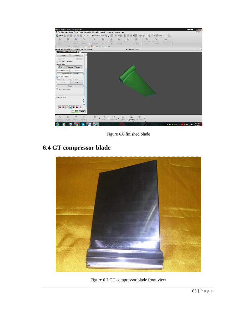
Figure 6.6 finished blade
6.4 GT compressor blade
Figure 6.7 GT compressor blade front view

64 | P a g e
Figure 6.8 GT compressor blade
6.5 INSPECTION RESULTS
--------------------------------------------------------------------------------
15-APRIL-2014 12:09 Start Template Page 1
--------------------------------------------------------------------------------
(mm) ACTUAL NOMINAL LO-TOL HI-TOL DEVIATION GRAPHIC
ERROR
--------------------------------------------------------------------------------
Temperature Compensation: OFF
Point:POINT1--Point:POINT2
Length 29.9921 23.0000 -0.1000 +0.1000 6.9921 ---+--> 6.8921
--------------------------------------------------------------------------------
Point:POINT1--Point:POINT2
Length 29.9921 30.0000 -0.1000 +0.1000 -0.0079 ---*---
--------------------------------------------------------------------------------
Point:PNT001
X-axis -12.4830 -12.3818 -0.0300 +0.0300 -0.1012 <--+--- -0.0712
Y-axis -13.1401 -13.0010 -0.0300 +0.0300 -0.1391 <--+--- -0.1091
Z-axis -10.0176 -10.0182 -0.0300 +0.0300 0.0006 ---*---
--------------------------------------------------------------------------------
Point:PNT002
X-axis -9.5722 -9.4692 -0.0300 +0.0300 -0.1030 <--+--- -0.0730
Y-axis -15.1805 -15.0404 -0.0300 +0.0300 -0.1401 <--+--- -0.1101

65 | P a g e
Z-axis -9.9816 -9.9820 -0.0300 +0.0300 0.0004 ---*---
--------------------------------------------------------------------------------
Point:PNT003
X-axis -6.5189 -6.4190 -0.0300 +0.0300 -0.0999 <--+--- -0.0699
Y-axis -17.3199 -17.1761 -0.0300 +0.0300 -0.1438 <--+--- -0.1138
Z-axis -9.9881 -9.9886 -0.0300 +0.0300 0.0005 ---*---
--------------------------------------------------------------------------------
Point:PNT011
X-axis -12.5390 -12.4308 -0.0300 +0.0300 -0.1082 <--+--- -0.0782
Y-axis 13.1171 12.9666 -0.0300 +0.0300 0.1505 ---+--> 0.1205
Z-axis -10.0069 -10.0075 -0.0300 +0.0300 0.0006 ---*---
--------------------------------------------------------------------------------
Point:PNT012
X-axis -9.5260 -9.4228 -0.0300 +0.0300 -0.1032 <--+--- -0.0732
Y-axis 15.2258 15.0729 -0.0300 +0.0300 0.1529 ---+--> 0.1229
Z-axis -9.9969 -9.9983 -0.0300 +0.0300 0.0014 ---*---
--------------------------------------------------------------------------------
Point:PNT013
X-axis -6.8092 -6.7058 -0.0300 +0.0300 -0.1034 <--+--- -0.0734
Y-axis 17.1271 16.9753 -0.0300 +0.0300 0.1518 ---+--> 0.1218
Z-axis -10.0060 -10.0073 -0.0300 +0.0300 0.0013 ---*---
--------------------------------------------------------------------------------
Point:PNT004
X-axis -12.2900 -12.1943 -0.0300 +0.0300 -0.0957 <--+--- -0.0657
Y-axis -13.2624 -13.1322 -0.0300 +0.0300 -0.1302 <--+--- -0.1002
Z-axis -94.9907 -94.9914 -0.0300 +0.0300 0.0007 ---*---
--------------------------------------------------------------------------------
Point:PNT005
X-axis -9.4002 -9.3049 -0.0300 +0.0300 -0.0953 <--+--- -0.0653
Y-axis -15.2882 -15.1554 -0.0300 +0.0300 -0.1328 <--+--- -0.1028
Z-axis -95.0013 -95.0025 -0.0300 +0.0300 0.0012 ---*---
--------------------------------------------------------------------------------
Point:PNT006
X-axis -6.7887 -6.6950 -0.0300 +0.0300 -0.0937 <--+--- -0.0637
Y-axis -17.1194 -16.9829 -0.0300 +0.0300 -0.1365 <--+--- -0.1065
Z-axis -94.9916 -94.9921 -0.0300 +0.0300 0.0005 ---*---
--------------------------------------------------------------------------------
Point:PNT014
X-axis -12.2901 -12.2038 -0.0300 +0.0300 -0.0863 <--+--- -0.0563
===============================================================
=================

66 | P a g e
15-APRIL-2014 12:09 Start Template Page 2
--------------------------------------------------------------------------------
(mm) ACTUAL NOMINAL LO-TOL HI-TOL DEVIATION GRAPHIC
ERROR
--------------------------------------------------------------------------------
Y-axis 13.2435 13.1255 -0.0300 +0.0300 0.1180 ---+--> 0.0880
Z-axis -95.0111 -95.0121 -0.0300 +0.0300 0.0010 ---*---
--------------------------------------------------------------------------------
Point:PNT015
X-axis -9.5297 -9.4525 -0.0300 +0.0300 -0.0772 <--+--- -0.0472
Y-axis 15.1758 15.0521 -0.0300 +0.0300 0.1237 ---+--> 0.0937
Z-axis -95.0132 -95.0142 -0.0300 +0.0300 0.0010 ---*---
--------------------------------------------------------------------------------
Point:PNT016
X-axis -7.1900 -7.1085 -0.0300 +0.0300 -0.0815 <--+--- -0.0515
Y-axis 16.8143 16.6933 -0.0300 +0.0300 0.1210 ---+--> 0.0910
Z-axis -95.0350 -95.0361 -0.0300 +0.0300 0.0011 ---*---
--------------------------------------------------------------------------------
Point:PNT009
X-axis -4.3095 -4.2438 -0.2000 +0.2000 -0.0657 --*+---
Y-axis -17.2432 -17.3473 -0.2000 +0.2000 0.1041 ---+-*-
Z-axis -10.0029 -10.0040 -0.2000 +0.2000 0.0011 ---*---
--------------------------------------------------------------------------------
Point:PNT010
X-axis -1.5744 -1.5120 -0.2000 +0.2000 -0.0624 --*+---
Y-axis -15.6324 -15.7382 -0.2000 +0.2000 0.1058 ---+-*-
Z-axis -10.0290 -10.0293 -0.2000 +0.2000 0.0003 ---*---
--------------------------------------------------------------------------------
Point:PNT019
X-axis -1.2959 -1.2375 -0.2000 +0.2000 -0.0584 --*+---
Y-axis 15.4808 15.5765 -0.2000 +0.2000 -0.0957 --*+---
Z-axis -10.0012 -10.0031 -0.2000 +0.2000 0.0019 ---*---
--------------------------------------------------------------------------------
Point:PNT020
X-axis -4.3593 -4.3022 -0.2000 +0.2000 -0.0571 --*+---
Y-axis 17.2882 17.3818 -0.2000 +0.2000 -0.0936 --*+---
Z-axis -9.9847 -9.9857 -0.2000 +0.2000 0.0010 ---*---
--------------------------------------------------------------------------------
Point:PNT007
X-axis -4.2809 -4.2388 -0.2000 +0.2000 -0.0421 --*+---
Y-axis -17.2789 -17.3444 -0.2000 +0.2000 0.0655 ---+*--
Z-axis -95.0162 -95.0167 -0.2000 +0.2000 0.0005 ---*---
--------------------------------------------------------------------------------
Point:PNT008
X-axis -1.2622 -1.2253 -0.2000 +0.2000 -0.0369 --*+---
Y-axis -15.5018 -15.5693 -0.2000 +0.2000 0.0675 ---+*--

67 | P a g e
Z-axis -94.9986 -94.9991 -0.2000 +0.2000 0.0005 ---*---
--------------------------------------------------------------------------------
Point:PNT017
X-axis -4.1095 -4.0569 -0.2000 +0.2000 -0.0526 --*+---
Y-axis 17.1505 17.2373 -0.2000 +0.2000 -0.0868 --*+---
Z-axis -94.9903 -94.9914 -0.2000 +0.2000 0.0011 ---*---
--------------------------------------------------------------------------------
Point:PNT018
X-axis -1.1281 -1.0741 -0.2000 +0.2000 -0.0540 --*+---
Y-axis 15.3916 15.4803 -0.2000 +0.2000 -0.0887 --*+---
Z-axis -95.0094 -95.0106 -0.2000 +0.2000 0.0012 ---*---
--------------------------------------------------------------------------------
Plane:PLN001--Plane:PLN002
===============================================================
=================
--------------------------------------------------------------------------------
15-APRIL-2014 12:09 Start Template Page 3
--------------------------------------------------------------------------------
(mm) ACTUAL NOMINAL LO-TOL HI-TOL DEVIATION GRAPHIC
ERROR
--------------------------------------------------------------------------------
Angle-XY 70.0201 70.0000 -0.1000 +0.1000 0.0201 ---+*--
--------------------------------------------------------------------------------
Plane:PLN003--Plane:PLN004
Angle-XY -61.0297 0.0000 -0.1000 +0.1000 -61.0297 <--+--- -60.9297
--------------------------------------------------------------------------------
Plane:PLN003--Plane:PLN004
Angle-XY 61.0297 61.0000 -0.1000 +0.1000 0.0297 ---+*--
--------------------------------------------------------------------------------
68 | P a g e
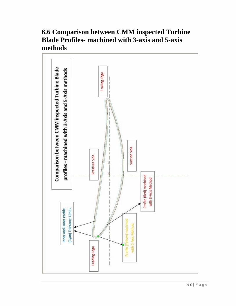
6.6 Comparison between CMM inspected Turbine
Blade Profiles- machined with 3-axis and 5-axis
methods
69 | P a g e
The comparison of the turbine blade profiles machined with 3-axis and 5-axis
methods can be carried out by overlapping the output digigraphs from the CMM of both
the methods. See the above figure.
Inner and Outer Profile (Cyan) Tolerance Limits are +/- 100μ.
When machined with 3-axis method,
The pressure and suction sides are undercut, due to the curvatures.
The trailing and the leading edges are overcut due to run away and the
vibrations in the machine.
When machined with 5-axis method,
The blade profile machined is neither undercut nor overcut as the machining is
not affected by the vibrations of the machine.
Thus the accuracy of the machined blade in 5-axis method is higher than that of the
3-axis method thus increasing the quality of the machining.
70 | P a g e
6.7 CONCLUSION
Modeling, manufacturing and inspection procedure of the GT compressor blade
has been discussed in the report. The type of milling technique used is Sturz Milling,
which may not be a new technique in manufacturing, but it's application in CNC
machining of turbine blades opens a new chapter in turbo machinery manufacturing
industry.
5-axis machining is observed to be more productive over conventional 3-axis
machining. The machining time has been reduced to 2hrs, with a higher surface finish in
single setup.
Thus 5-axis machining using Struz milling techniques for the manufacturing of GT
compressor turbine blades gives a superior quality.

71 | P a g e
REFERENCES
1. "An Integrated Turbine Blade Manufacturing System" by Randy Schmid,
Published in AUTOFACT 6, 1984.
2. Unigraphics V10.4.1 CAD/CAM software manuals.
3. C.G. Jensen, W.E. Red, J. Pi (2002), “Tool selection for five-axis curvature
matched machining ”, Computer Aided Design vol. 34, pp. 251-266
4. NX Manufacturing Fundamentals, Student Guide, April 2007, Publication Number
MT11021 — NX 5
5. Dunham, J. A parametric method of Turbine Blade Profile design, ASME Paper
74-GT-119, 1974
6. Korakianitis, T. and Pantazoupulos, G.I.: Improved Turbine-Blade Design
techniques
7. using 4th order paramertic spline segments, Computer Aided design, Vol. 25,
No.5, pp.289-299,1993.