Embed Size (px)
Citation preview
HYBRID (HHP) HEAT PUMPS
INSTALLATION - OPERATION - MAINTENANCE
omegaheatpumps.com | T. 905.670.3200 | F. 905.670.3822
MANUFACTURERS OF ULTRA-QUIET
OMEGA | HYBRID HEAT PUMPS
2 www.omega-heatpumps.com
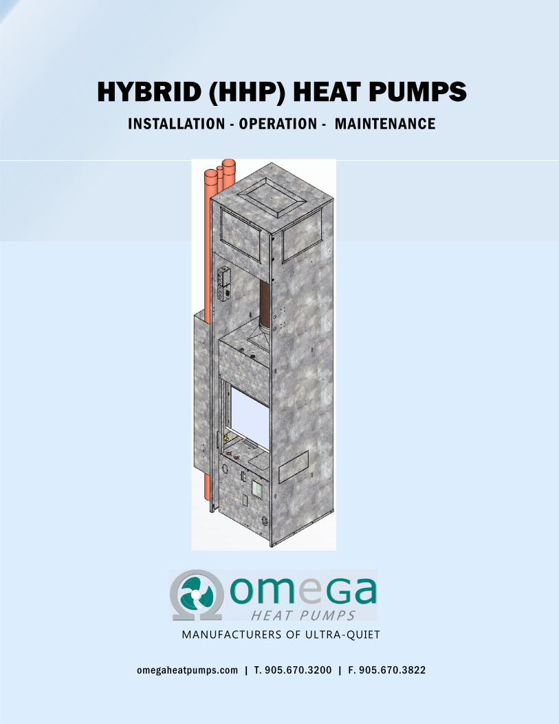
SAFETY
WARNING
This informa on is intended for use only by qualified
personnel with background of Electrical and Mechanical
experience. Installa on or Servicing the equipment may
result in personal injury and/or property damage. Manu-
facturer cannot be responsible or liable for any scenario.
WARNING Unit Contains R-410A Refrigerant. R-410A opera ng
pressure are greater than R22. Proper service equip-
ment is required for installa on/Service. Failure to use R-
410A compa ble tools may result in equipment damage
and Personal Injury
WARNING The Unit contains live electrical components. Qualified
personnel must follow all electrical safety precau ons
during installa on, tes ng, servicing and troubleshoo ng
of this product. Failure to follow these safety precau ons
may result in serious injuries or death.
WATER SOURCE HEAT PU MPS | OMEGA
www.omega-heatpumps.com 3
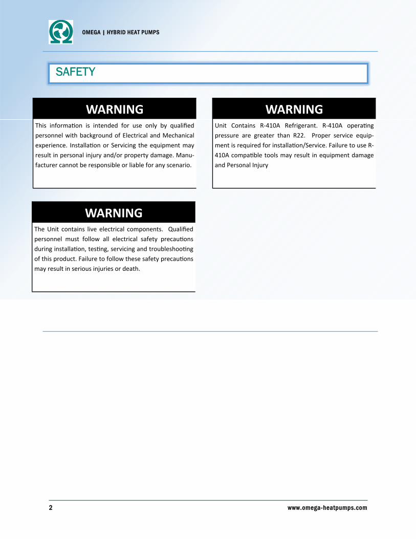
TABLE OF CONTENTS
1. PRODUCT OVERVIEW ..................................................... 4 1.1 Key Features ............................................................ 5
2. TRANSPORTATION AND STORAGE ......................... 6
3. MODEL NOMENCLATURE ........................................... 7
4. INSTALLATION ................................................................ 8
5. START-UP PROCEDURE .................................................. 9
6. OPERATION LIMITS AND ELECTRICAL DATA ...... 10
7. ELECTRICAL CONTROLS ............................................. 11 7.1 Wiring Diagram ..................................................... 11
7.2 Fan Motor Control and Connec ons ..................... 14
7.3 Sequence of Opera ons ........................................ 15
7.3 Alarms .................................................................... 17
8. MAINTENANCE ................................................................ 19
9. WARRANTY ........................................................................ 18

OMEGA | HYBRID HEAT PUMPS
4 www.omega-heatpumps.com
The entire Omega HHP (Hybrid Heat Pump) product line is engineered to provide the quietest vertical stacking water-source hybrid heat pump in the indus-try—and thousands of installed units have proven this in the field. Properly applied and installed, all our units easily meet NC 36 - 40 within the suite.
Dependable
Our Water-source Hybrid Heat Pump systems provide easy and reliable year round heating and cooling to the occupants of your Apartments and Condomini-ums. Simply set the desired temperature and the hybrid heat pump will maintain it.
Energy Efficient
Unlike Fan Coil systems, the Hybrid (HHP) system can transfer energy from one zone to another. During moderate weather, the sunny side of a building may require cooling while the shady side requires heating. In addition, Hybrid Heat Pump system is designed to use compressor (Refrigerant Circuit) only for Cooling purposes. Therefore, unit saves additional energy by running as conventional Fan Coil unit for Heating.
Serviceability
Each HHP unit has its own compressor and fan which are easily accessible through the Return air panel. If repairs are required, a spare chassis can be inserted into the unit, allowing it to continuously operate while the damaged chassis is repaired offsite.
Customizable
Omega Heat Pump units can be easily customized to meet the specific requirements of any project. Some options include: choice of supply air discharge loca-tions and sizes, ultra quiet Acoustic Return Air Panel, and remote Thermostat control.
Elegant phased installation
The equipment is shipped to the site in two stages to integrate nicely with the phases of construction. This reduces on-site damage and allow mechanical units to be installed indoors, out of the weather.
During the initial stages of construction, the outer casing and plenum are installed. As construction pro-gresses, these become part of the interior wall struc-ture. The final chassis is delivered for installation af-ter the majority of construction is complete and be-comes fully integrated into the interior of the unit.
Testing & quality
To maintain the highest level of quality control, each unit is checked in our state-of-the-art test facility be-fore being shipped to the job site. Large scale produc-tion accommodates short lead-times and economies of scale enable low costs without sacrificing quality.
State-of-the-art manufacturing and rigorous quality control systems guarantees every HHP is manufac-tured with the highest degree of reliability and con-sistency. In the chassis production line, a 6-station QC system ensures that every stage of chassis pro-duction is tested and re-tested, and that each unit complies with ARI published guidelines. Lean Six Sig-ma procedures result in efficient and cost effective manufacturing that drives a high quality—and highly competitive—product.
1. PRODUCT OVERVIEW
WATER SOURCE HEAT PU MPS | OMEGA
www.omega-heatpumps.com 5
1. PRODUCT OVERVIEW
1.1 Key Features
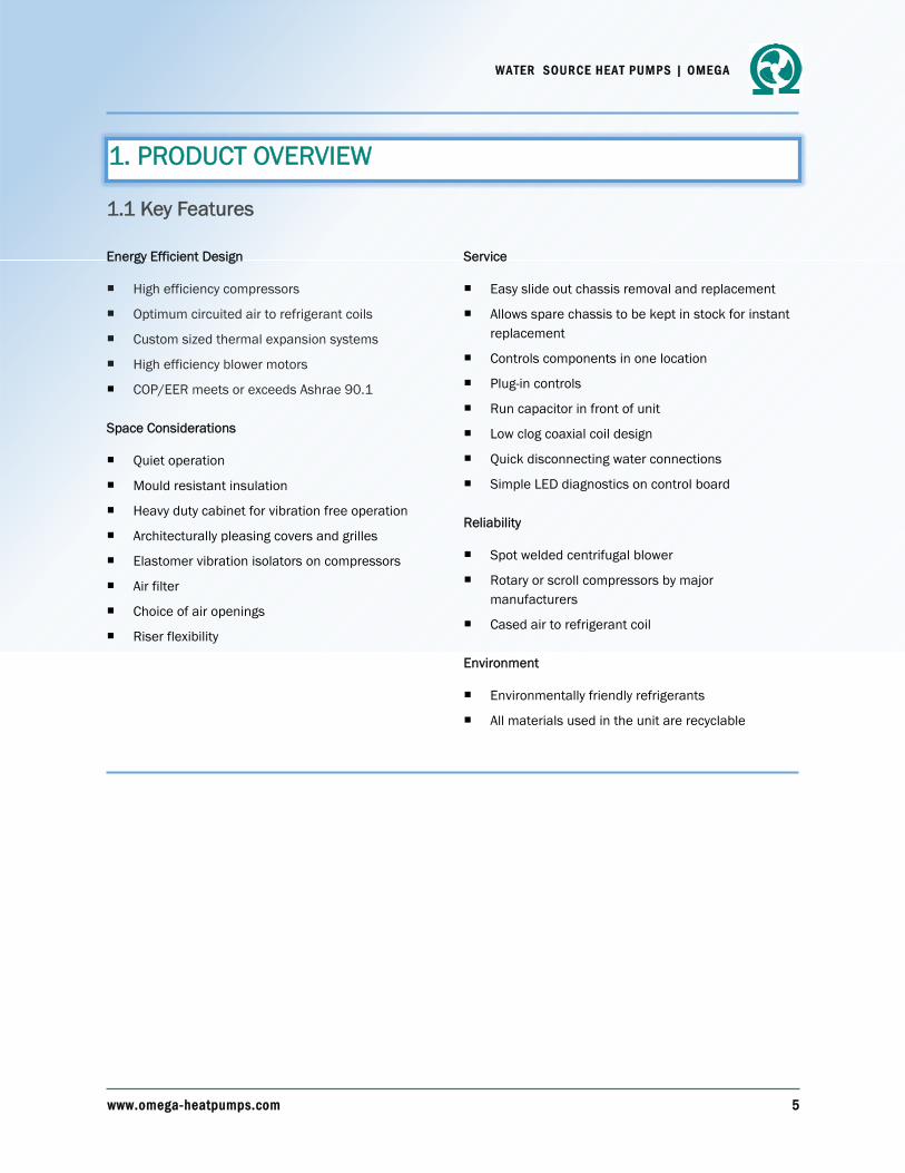
Energy Efficient Design
High efficiency compressors
Optimum circuited air to refrigerant coils
Custom sized thermal expansion systems
High efficiency blower motors
COP/EER meets or exceeds Ashrae 90.1
Space Considerations
Quiet operation
Mould resistant insulation
Heavy duty cabinet for vibration free operation
Architecturally pleasing covers and grilles
Elastomer vibration isolators on compressors
Air filter
Choice of air openings
Riser flexibility
Service
Easy slide out chassis removal and replacement
Allows spare chassis to be kept in stock for instant replacement
Controls components in one location
Plug-in controls
Run capacitor in front of unit
Low clog coaxial coil design
Quick disconnecting water connections
Simple LED diagnostics on control board
Reliability
Spot welded centrifugal blower
Rotary or scroll compressors by major manufacturers
Cased air to refrigerant coil
Environment
Environmentally friendly refrigerants
All materials used in the unit are recyclable
OMEGA | HYBRID HEAT PUMPS
6 www.omega-heatpumps.com
2. TRANSPORTATION AND STORAGE
Each Omega Heat Pump unit is checked in our state-of-the-art test facility before being shipped to the job site. For ease of transportation and safety of equipment, Units are shipped in secured packaging. Nevertheless, Units must be handled by care to avoid any damage.
Upon receipt of the equipment, check packaging for visible damage and notify Shipper about any such damages before signing delivery ticket. If there is any evidence of rough handling, immediately open the cartons to check for hidden damage. In case of dam-aged equipment, it is receiver’s responsibility to notify the carrier within 48 hours to es-tablish claim and request their inspection and report. Contact Omega’s Warranty Claims Department only after notifying carrier.
All cartons should be transported and stored in their upright position. If it is necessary to place units in other than their upright position for on-site transfer, the units must be placed in their normal upright position for at least 24 hours before attempting to start them.
All Omega Heat pump units must be stored indoor in non-corrosive environment where it is completely sheltered from rain, snow, etc. Excessively high or low temperatures and humidity may deteriorate certain unit components causing permanent damage. It is rec-ommended to place chassis in room conditions before installation.

WATER SOURCE HEAT PU MPS | OMEGA
www.omega-heatpumps.com 7
HHP‐30
3. MODEL NOMENCLATURE
Unit Size Tonnage CFM
HHP-20 1/2 Ton 230
HHP-30 3/4 Ton 300
HHP-40 1 1/4 Tons 400
HHP-50 1 3/4 Tons 500
HHP-60 1 1/2 Tons 600
HHP-80 2 Tons 800
HHP-100 2 1/2 Tons 1000
HHP-120 3 Tons 1200
Type: Hybrid Heat Pump Unit Size
OMEGA | HYBRID HEAT PUMPS
8 www.omega-heatpumps.com
4. INSTALLATION
General
1. To prevent damage this equipment should not be operated for supplementary heating and cool-ing during the construction period.
2. Inspect the cartons and pallets for any specific tagging numbers indicated by Omega per request from the installing contractor. At this time the voltage, phase and capacity should be checked against the plans.
3. Check tagging numbers against the plans to ensure unit installation in the correct location.
4. The installing contractor will find it beneficial to confer with piping, sheet metal, ceiling and elec-trical foremen, together, before installing any conditioners.
Chassis
1. Remove chassis from its carton. Connect supply and return water hoses to the ball valves on heat pump. Connect supply and return water hoses to the chassis. Observe industry standard for tightening of flare fittings. (See Start up Procedure for further detail)
2. Connect electrical quick connect plug to matching receptacle on the cabinet mounted control box.
3. Slide the chassis into the cabinet until the outside flanges are flush with the front. Install the coil block off panel
Return Air 1. Screw architectural acoustical front panel to the dry wall furring as per detail in shop drawings.

WATER SOURCE HEAT PU MPS | OMEGA
www.omega-heatpumps.com 9
5. START-UP PROCEDURE
The following is designed to guide you through the process of flushing the HHP system. Failure to per-
form any of the steps below will result in the termina on of the manufacture’s warranty.
Prior to first opera on of any HHP unit the water circula ng system must be cleaned and flushed of
all construc on dirt and debris. The chassis cannot be connected to system when flushing is being
conducted. Supply and return pipes must be interconnected with factory supplied hoses to proper-
ly flush system. This will prevent the introduc on of dirt into the chassis.
Before filling installer should ensure all flare fi ng connec ons to the heat pumps meet industry
standards. (Finger ght plus 1/4 turn with wrench.)
Fill system at city water makeup connec on with all air vents open. A er filling close all air vents
assure that boiler and heat rejecter are off but flow is allowed through each. The installer/
contractor should start main circula ng pump with pressure reducing makeup valve open. Check
vents in sequence to bleed off any trapped air, assuring circula on through all components of the
system.
Shut off circula ng pump and open all drains and vents to completely drain the system. Short cir-
cuited supply and return runouts should now be connected to the HHP unit with factory supplied
supply and return hoses. Teflon tape is recommended instead of pipe dope for pipe thread connec-
ons. Use no sealers at the swivel flare connec ons of hoses.
Trisodium phosphate is recommended as a cleaning agent during flushing. However, many locali-
es prohibit the introduc on of phosphates into their sewage systems. The current recommenda-
on is to contact your local water treatment specialist.
Refill the system with clean water. Test with litmus paper for acidity, and treat as required to leave
the water slightly alkaline (pH 7.5 to 8.5). The specified percentage of an freeze may also be added
at this me. Use commercial grade an freeze designed for HVAC systems only. Do not use automo-
ve grade an freeze.
Installing contractor to provide wri en confirma on that the system was properly flushed and bal-
anced. An independent flushing & balancing agency must be used. Once this is complete a proper
start can be completed by HHP start-up contractor by a aching other chassis to the system.
Set the system heat add set point and the heat rejec on set point as required. Supply power to all
motors and start the circula ng pumps. A er full flow has been established through all compo-
nents including the heat rejector (regardless of season) and air vented and loop temperatures sta-
bilized, each of the HHP units will be ready for check, test and start-up and for air and water bal-
ancing.

OMEGA | HYBRID HEAT PUMPS
10 www.omega-heatpumps.com
6. OPERATION LIMITS AND ELECTRICAL DATA
This equipment is designed for indoor installation only. Sheltered locations such as attics, garages, etc., generally will not provide sufficient protection against extremes in temperature and/or humidi-ty, and equipment performance, reliability, and service life may be adversely affected.
4.1 Water Temperature
Standard Entering Air Dry Bulb Temperature: 80°F for Cooling and 68°F for Heating
Standard Entering Air Wet Bulb Temperature: 67°F for Cooling and 59°F for Heating
Minimum Ambient Air: 50°F for Cooling and Heating
Maximum Ambient Air: 110°F for Cooling and 85°F for Heating
4.2 Air Temperature
Recommended Water loop SUPPLY temperature:
For Heating: 90°F to 110°F
For Cooling:: 86°F to 105°F
4.3 ELECTRICAL DATA
Unit Size Volts/Phase/Cycle Breaker (Amps)
HHP‐30 208/1/60 15A
HHP‐40 208/1/60 15A
HHP‐60 208/1/60 20A
HHP‐80 208/1/60 25A
HHP‐100 208/1/60 30A
HHP‐120 208/1/60 35A

WATER SOURCE HEAT PU MPS | OMEGA
www.omega-heatpumps.com 11
7. ELECTRICAL CONTROLS

OMEGA | HYBRID HEAT PUMPS
12 www.omega-heatpumps.com
7. ELECTRICAL CONTROLS

WATER SOURCE HEAT PU MPS | OMEGA
www.omega-heatpumps.com 13
7. ELECTRICAL CONTROLS

OMEGA | HYBRID HEAT PUMPS
14 www.omega-heatpumps.com
7. ELECTRICAL CONTROLS
7.2.1 STANDARD HYBRID HEAT PUMP DIP SWITCH CONFIGURATION
Fan Control of PSC Motors
Omega utilizes standard 3 speed PSC motors across its entire product line. The PSC Fan Relay Pack is utilized to enable individual fan motor speeds. See diagram.
Fan Control of ECM EON42 Motors
Omega utilizes the EON 42 ECM motor for its smaller sized heat pumps. The EON 42 ECM motor uses DISCRETE speed mode. In DISCRETE mode, the EON-42 motor is factory programmed with a specific speed for each of its 3 taps. EON-42 taps are selected by applying 208VAC on the required TAP. The EON 42 ECM motor utilizes the Fan Relay Pack for discrete mode. See diagram.
7.2.2 FAN MOTOR CONTROL AND CONNECTIONS
Following are the Configurations available for DIP SWITCHES on Hybrid Heat Pump Control Boards.
Unless specified by Customer, the “DEFAULT” Dip Switch setting shown in above table will be set on Control Boards for Hybrid Heat Pumps
Thermostat Type
Heat Pump Type
Flow Type Coax Valve Control Action
Heat Coil Valve Control
Action DIP1-1 DIP1-2 DIP1-3 DIP1-4 DIP1-5
Heat Pump Thermostat
DIP1-1=ON
DEFAULT
Standard HP
DIP1-2=ON
Constant Flow
DIP1-3=ON
NC Valve
DIP1-4=ON
DEFAULT
NC Valve
DIP1-5=ON
DEFAULT
Conventional Heat/Cool
Thermostat
DIP1-1=OFF
Hybrid HP
DIP1-2=OFF
DEFAULT
Variable Flow
DIP1-3=OFF
DEFAULT
NO Valve
DIP1-4=ON
NO Valve
DIP1-5=ON
Fan Mode
DIP1-6 Automatic Fan speed control
using Thermostat
DIP1-6=ON
Manual Fan Speed control through Switch
DIP1-6= OFF
DEFAULT

WATER SOURCE HEAT PU MPS | OMEGA
www.omega-heatpumps.com 15
7. ELECTRICAL CONTROLS
7.3 SEQUENCE OF OPERATION
Fan Control
In AUTO fan control mode (DIP1-6 = ON), thermostat inputs G1, G2 and G3 control fan speeds Low, Medium and High speed.
In Manual fan control mode (DIP1-6 = OFF), any single thermostat input on G1, G2 or G3 directly enables a fan request. When a fan request is made, the fan speed is determined by input of 3 posi-tion switch, which is mapped to – low, medium or high speed.
Special Considerations
All G inputs are software debounced for 1 second before registering a change of state.
It is possible to have all inputs G1, G2 and G3 OFF when switching between Fan speeds. To eliminate nuisance cycling of these fan inputs, all G inputs must be OFF for 3 seconds before a fan request of OFF is registered
Calls for Heating and Cooling
Calls for Heating and Cooling are initiated by the thermostat.
If a HEAT PUMP thermostat is used, then DIP1-1 should be set to ON.
Y Terminal Closed = call for compressor.
O/B Terminal Open = reversing valve de-energized = call for HEATING.
O/B Terminal Closed = reversing valve energized = call for COOLING.
If a HEAT/COOL thermostat is used, then DIP1-1 should be set to OFF.
Y Terminal Closed = call for COOLING.
W Terminal Closed = call for HEATING.
Note: If both Y and O are closed, a call for HEATING is assumed.

OMEGA | HYBRID HEAT PUMPS
16 www.omega-heatpumps.com
7. ELECTRICAL CONTROLS
7.3 SEQUENCE OF OPERATION
Call for Cooling: For Hybrid Heat Pumps when there is call from T-STAT for “Cooling” , request for Compressor is Made. Request for Compressor
When a compressor request is made, the COAX Flow valve will be opened (if not already open). The compressor contractor will then be energized if the following conditions are met:
Water flow through the coax exists for a minimum of 3 minutes (adjustable). (INTERLOCK)
The fan has been running a minimum of 3 minutes (adjustable). (INTERLOCK)
No High Pressure Alarm (HP_ALARM)
No Low Pressure Alarm (LP_ALARM)
No Condensate Over Flow Alarm (CO_ALARM)
The Compressor Anti-Recycle Timer of 7 minutes (adjustable) has expired. (ARTIMER)
The Water Loop Temperature is within design range
Greater than 115 DegF (adjustable) on Water Supply WLST (In to Coax)
Greater than 127 DegF (adjustable) on Water Discharge WLDT (Out of Coax)
When a compressor request is terminated, the COAX will be flushed for 3 minutes (adjustable) and the fan will remain on for 3 minutes (adjustable) to flush the air coil. Call for Heating: When there is call from T-STAT for “Heating”, the Heating Coil Valve will be Opened. When request is met, fan will remain on for 3 minutes (adjustable) to flush the air coil. Constant Flow vs Variable Flow Constant Flow: For a hybrid heat pump with Constant flow, the flow is directed to COAX when the compressor is called ON or there is no call for heating or cooling. If there is a call for heating, the flow is directed through the heating coil. Variable Flow: For hybrid heat pumps with Variable flow, flow is directed to the COAX on a call for cooling, to the heating coils on a call for heating. If there is no call for heating or cooling, flow is disabled.

WATER SOURCE HEAT PU MPS | OMEGA
www.omega-heatpumps.com 17
7. ELECTRICAL CONTROLS
7.4 ALARMS
HP Alarm – High Pressure (Latching Alarm) (NC-opens on fault)
A high pressure alarm will occur when the HP Switch opens
The red HP_LED will be illuminated SOLID when a HP Alarm occurs.
This is a latching alarm that will clear only if power is cycled to the unit
LP Alarm – Low Pressure (Latching Alarm) (NC-opens on fault)
LP ByPass Mode
If the LP switch is open and the compressor is running for less than 3 minutes (adjustable), a Low Pressure ByPass warning will be activated. If the LP Switch closes before 3 minutes (adjustable) expires, the ByPass timer will be reset.
The red LP_LED on will set BLINKING when in LP ByPass mode.
LP Alarm Mode
A low pressure alarm will occur when the compressor is running and the LP Switch is open for 3 continuous minutes (adjustable).
The red LP_LED will be illuminated SOLID when a LP Alarm occurs.
This is a latching alarm that will clear only if power is cycled to the unit
Notes:
1. If the LP Switch is open on unit power up, a LP Alarm is triggered IMMEDIATELY ( no 3 minute wait).
CO Alarm – Condensate Over Flow (Latching Alarm)
A condensate over flow alarm will occur if the water sensor input is less than 900 (adjustable) for 30 (adjustable) continuous seconds.
This is a latching alarm.

OMEGA | HYBRID HEAT PUMPS
18 www.omega-heatpumps.com
7. ELECTRICAL CONTROLS
7.4 ALARMS
To protect the Refrigerant Circuit from high water loop temperatures during “Cooling” mode, following alarms are included :
WLST Alarm - Water Loop Discharge Temperature (NON-Latching Alarm)
The water loop SUPPLY temperature is ONLY tested when the COAX Flow Valve is open.
A water loop SUPPLY temperature greater than 115°F (Cut Out) will trip a WLST Alarm and temper-ature of 110°F (Cut In) or less will reset the WLST Alarm.
The WLST LED will be illuminated SOLID on a WLST Alarm.
This is a NON-LATCHING ALARM, it will lock out compressor operation until the water supply goes below the 110°F (Cut In temperature).
Notes:
If the WLST Sensor is sensed open (missing) or closed (shorted), a WLST ALARM is triggered.
The red WLST_LED will be set blinking.
WLDT Alarm - Water Loop Discharge Temperature (NON-Latching Alarm)
The water loop DISCHARGE temperature is ONLY tested when the COAX Flow Valve is open.
A water loop DISCHARGE temperature greater than 127°F (Cut Out) will trip a WLDT Alarm.
A water loop DISCHARGE temperature of less than 122°F (Cut In) will reset the WLDT Alarm.
The WLDT LED will be illuminated SOLID on a WLDT Alarm.
This is a NON-LATCHING ALARM, it will lock out compressor operation until the water supply goes below the 122°F (Cut In temperature).
Notes:
If the WLDT Sensor is sensed open (missing) or closed (shorted), a WLDT ALARM is triggered.
The red WLDT_LED will be set blinking for this type of alarm.
RST Alarm – Refrigerant Suction Temperature (NON-Latching Alarm)
RST temperature is simply monitored for logging and display purposes. It is not actively used in con-trol.
If the RST Sensor is sensed open (missing) or closed (shorted), a RST ALARM is triggered.
The red RST_LED will be set blinking for this type of alarm.
This is a NON-LATCHING ALARM and not used in any control.

WATER SOURCE HEAT PU MPS | OMEGA
www.omega-heatpumps.com 19
8. MAINTENANCE
Omega’s water source heat pump has minimum maintenance requirements that should be fol-lowed to fully ensure efficient, and proper operation. The following maintenance activities should be timely performed on the specified time intervals.
Important Note: Disconnect Power to the unit before removing Inner Panel to access the Coil.
Standard Maintenance (Every 60 days)
1. Check and inspect the filter for dirt and clogging, and replace when necessary.
2. Vacuum dust from the unit and air grilles
Bi-annual Maintenance (Every 6 months)
1. Clean the unit drain pan with a household anti-bacterial detergent.
2. Spray the unit air coil with a household anti-odour spray.
Annual Maintenance (Once a year)
1. Completely clean the interior of the unit
2. Spray the air coil with a household anti-odour spray.
3. Check the thermostat for proper operation.
4. The condensate drain pan should be checked annually and cleaned and flushed as re-quired.
5. If the unit was equipped with a humidifier, inspect and clean the unit.
6. Thoroughly wash the air coil.

OMEGA HEAT PUMP INC.
Omega Heat Pumps ‐ 3325A Orlando Drive ‐ Mississauga, ON, Canada ‐ L4V 1C5 ‐ (905) 670‐2269 ‐ omega@omega‐heatpump.com
GENERAL This limited warranty is applicable to the HRP/HHP series Water Source Heat Pumps manufactured by Omega Heat Pump Inc. and
used in RESIDENTIAL installations.
LIMITED WARRANTY ON PARTS Omega Heat Pumps warrants all parts of the HRP/HHP water source heat pump used in Residential applications to be free from defects in workmanship and materials for normal use for the time periods set forth herein. Any part or portion thereof (except air filters) which becomes defective under normal use during the period of this warranty will be repaired or replaced provided the Company’s examination shall prove to its satisfaction that the part was or became defective under normal use.
However, Labour charges, shipping charges for replacement parts, replacement of refrigerant or filters and any other service repairs are not covered by this Limited Warranty. It also does not cover any portion or component of the system that is not supplied by Omega Heat Pumps, regardless of the cause of failure of such portion or component.
PERIOD OF COVERAGE
This limited warranty applies for one year from the date of initial operation or 18 months from the date of shipment, whichever is the
first to occur, to all parts and components in the Omega Heat Pumps product identified herein, except air filters which are not included
in any part of this limited warranty.
OMEGA HEAT PUMP MODEL NUMBER: _____________________
OMEGA HEAT PUMP SERIAL NUMBER: _____________________
DATE OF INITIAL OPERATION: _____________________________
LIMITED PARTS WARRANTY