Embed Size (px)
Citation preview
Manufacturer Specific Considerations for CT
AccreditationMelissa C. Martin, M.S., FAAPM, FACR
AAPM Spring Clinical Meeting March 20, 2012 Dallas, TX

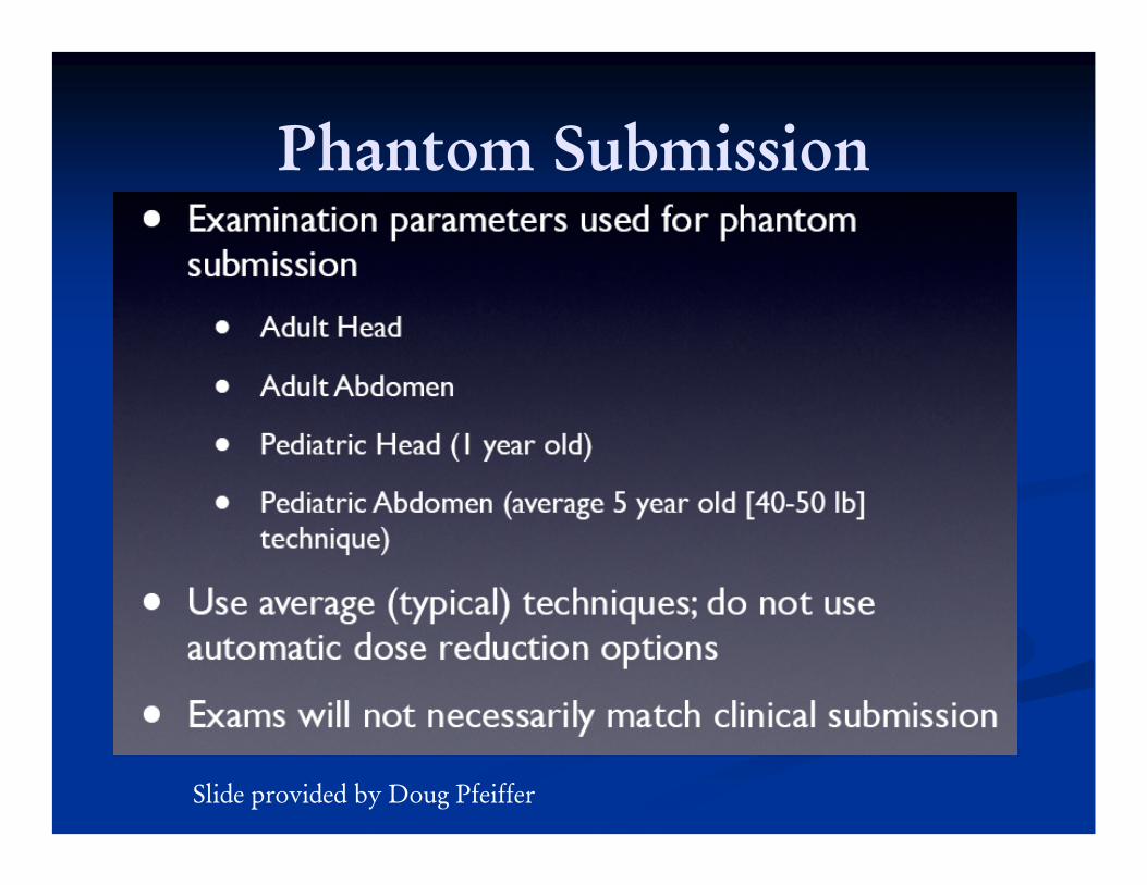
Phantom Submission
Slide provided by Doug Pfeiffer

Phantom Submission
Slide provided by Doug Pfeiffer
Phantom Submission
Slide provided by Doug Pfeiffer

Phantom Site Scanning Form -Page 1
Slide provided by Doug Pfeiffer

Phantom Site Scanning Data Form - Page 2
Slide provided by Doug Pfeiffer

Phantom Images
Slide provided by Doug Pfeiffer

Phantom Images
Slide provided by Doug Pfeiffer

Phantom Images
Slide provided by Doug Pfeiffer

Phantom Scoring
Slide provided by Doug Pfeiffer
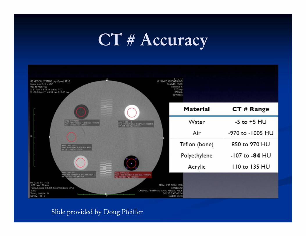
CT # Accuracy
Slide provided by Doug Pfeiffer

Contrast-Noise Ratio
Slide provided by Doug Pfeiffer

Contrast-Noise Ratio
Slide provided by Doug Pfeiffer

CT # Uniformity
Slide provided by Doug Pfeiffer

Dosimetry
Table 1 - Common MistakesFor mA row – entering mAs, effective mAs or mAs/sliceHelp site understand difference between these
And that they are not all equivalentmA ≠ mAsmAs ≠ eff. mAsmAs≠ mAs/slice

DosimetrySiemens – eff. mAs (effective mAs)
Philips – mAs/Slice (similar definition to eff. mAs)
Toshiba and GE use mA, time , Pitch as separate values
PitchtimerotmAmAsEff _*_. = timerot
PitchmAsEffmA_
*_.=
PitchtimerotmAslicemAs _*/ = timerot
PitchSlicemAsmA_
*)/(=

Dosimetry
Common Mistakes include:Reporting mAs or eff. mAs or mAs/slice in Table
1Then using mAs or eff. mAs when performing CTDI measurements
Example: 200 eff. mAs, pitch .9, rot. time = 0.5 secIn this case, mA = 360 Should perform CTDI measurement with 180 mAsSpreadsheet will use pitch 0.9 and correct for values of effective mAs

Dosimetry
Common Mistakes include:If site does this incorrectly, spreadsheet will have
incorrect valuesIf they perform acquisition with 200 mAsAnd then use N,T and I such that a pitch of 0.9 results, then CTDIvol reported will be too high
If Pitch < 1, CTDIvol reported will be too highIf Pitch > 1, CTDIvol reported will be too low
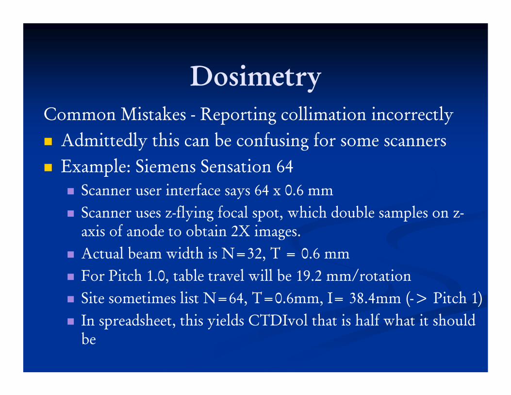
DosimetryCommon Mistakes - Reporting collimation incorrectly
Admittedly this can be confusing for some scannersExample: Siemens Sensation 64
Scanner user interface says 64 x 0.6 mmScanner uses z-flying focal spot, which double samples on z-axis of anode to obtain 2X images. Actual beam width is N=32, T = 0.6 mmFor Pitch 1.0, table travel will be 19.2 mm/rotationSite sometimes list N=64, T=0.6mm, I= 38.4mm (-> Pitch 1)In spreadsheet, this yields CTDIvol that is half what it should be

Dosimetry
Common Mistakes - Reporting collimation incorrectlyConsult ACR CT Accreditation website for FAQs and clarificationshttp://www.acr.org/accreditation/computed/ct_faq.aspx

Dosimetry
Slide provided by Doug Pfeiffer

Dosimetry
Slide provided by Doug Pfeiffer

Dosimetry
Slide provided by Doug Pfeiffer

Dosimetry
Slide provided by Doug Pfeiffer

Dose Levels
Slide provided by Doug Pfeiffer

Dosimetry
Slide provided by Doug Pfeiffer

Dosimetry
Slide provided by Doug Pfeiffer
Dosimetry
Slide provided by Doug Pfeiffer

Pass/Fail Criteria
Slide provided by Doug Pfeiffer
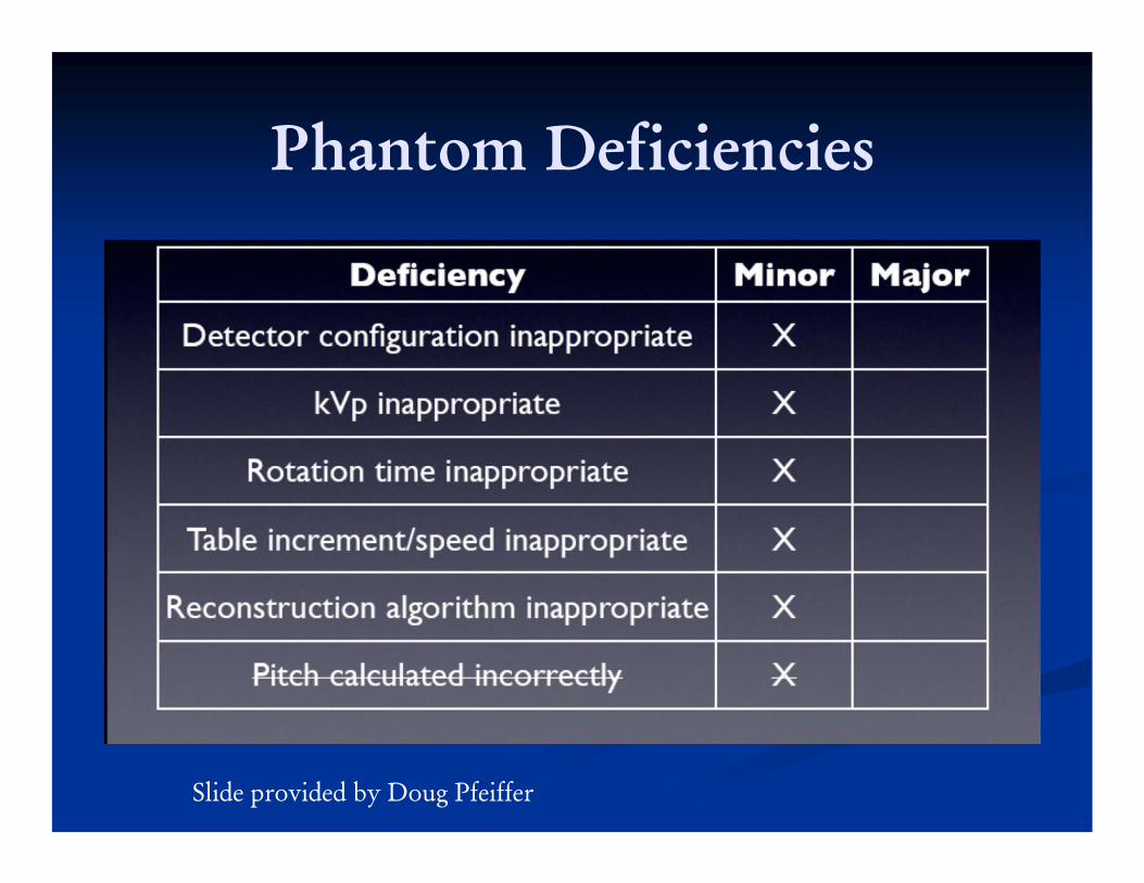
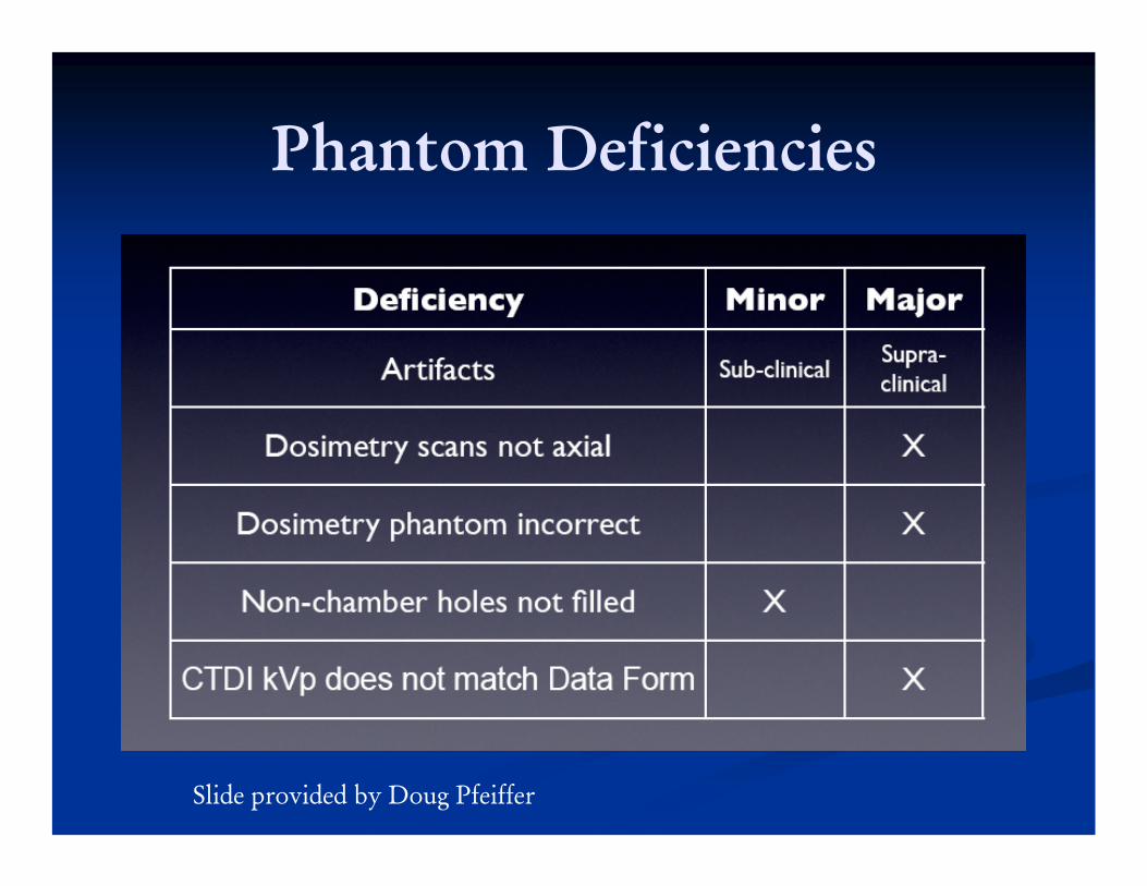
Phantom Deficiencies
Slide provided by Doug Pfeiffer

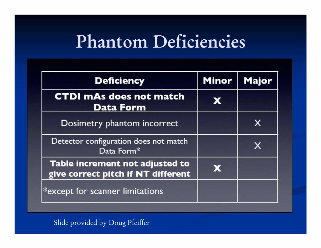
Phantom Deficiencies
Slide provided by Doug Pfeiffer
Phantom Deficiencies
Slide provided by Doug Pfeiffer
Phantom Deficiencies
Slide provided by Doug Pfeiffer

Slide provided by Doug Pfeiffer

Toshiba CT Scanners
Aquilion Scanners (32, 64 or 320)
Slide provided by Erin Angel, Toshiba Medical Systems

Toshiba Aquilion 32 or 64 slice CT Scanners
The maximum number of axial images able to be acquired simultaneously in a single rotation (Nmax) is 4.The minimum rotation time for a full 360rotation can be found in the product data sheet or via loading any helical protocol and choosing the lowest available 360 rotation time (note: grayed-out times are not available).
Slide provided by Erin Angel, Toshiba Medical Systems

Toshiba Aquilion 32 or 64 slice CT Scanners
Slice thicknesses available in helical mode include:0.5mm, 1.0mm, 2.0mm, 3.0mm, 5.0mm, 7.0mm,
and 10.0mm.Slice thicknesses available in axial mode include:
0.5mm, 1.0mm, 2.0mm, 3.0mm, 4.0mm, 6.0mm, 8.0mm, 12mm (16mm, 24mm, and 32mm are also available for non-clinical applications).
Available beam energies* are80 kVp, 100 kVp, 120 kVp, and 135 kVp
Slide provided by Erin Angel, Toshiba Medical Systems

Toshiba Aquilion 16 slice CT Scanners
The maximum number of axial images able to be acquired simultaneously in a single rotation (Nmax) is 4.The minimum rotation time for a full 360rotation can be found in the product data sheet or via loading any helical protocol and choosing the lowest available 360 rotation time (note: grayed-out times are not available).
Slide provided by Erin Angel, Toshiba Medical Systems
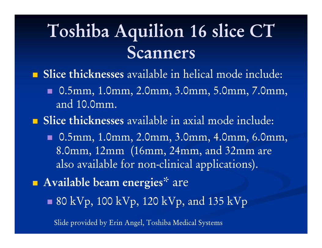
Toshiba Aquilion 16 slice CT Scanners
Slice thicknesses available in helical mode include:0.5mm, 1.0mm, 2.0mm, 3.0mm, 5.0mm, 7.0mm,
and 10.0mm.Slice thicknesses available in axial mode include:
0.5mm, 1.0mm, 2.0mm, 3.0mm, 4.0mm, 6.0mm, 8.0mm, 12mm (16mm, 24mm, and 32mm are also available for non-clinical applications).
Available beam energies* are80 kVp, 100 kVp, 120 kVp, and 135 kVp
Slide provided by Erin Angel, Toshiba Medical Systems

Toshiba Scanners - Location of Technical Parameters

Toshiba Scanners - Scan Detail Tab
Slide provided by Erin Angel, Toshiba Medical Systems

Slide provided by Erin Angel, Toshiba Medical Systems

Scan Details for Axial Scanning
Slide provided by Erin Angel, Toshiba Medical Systems

Recon Details Tab
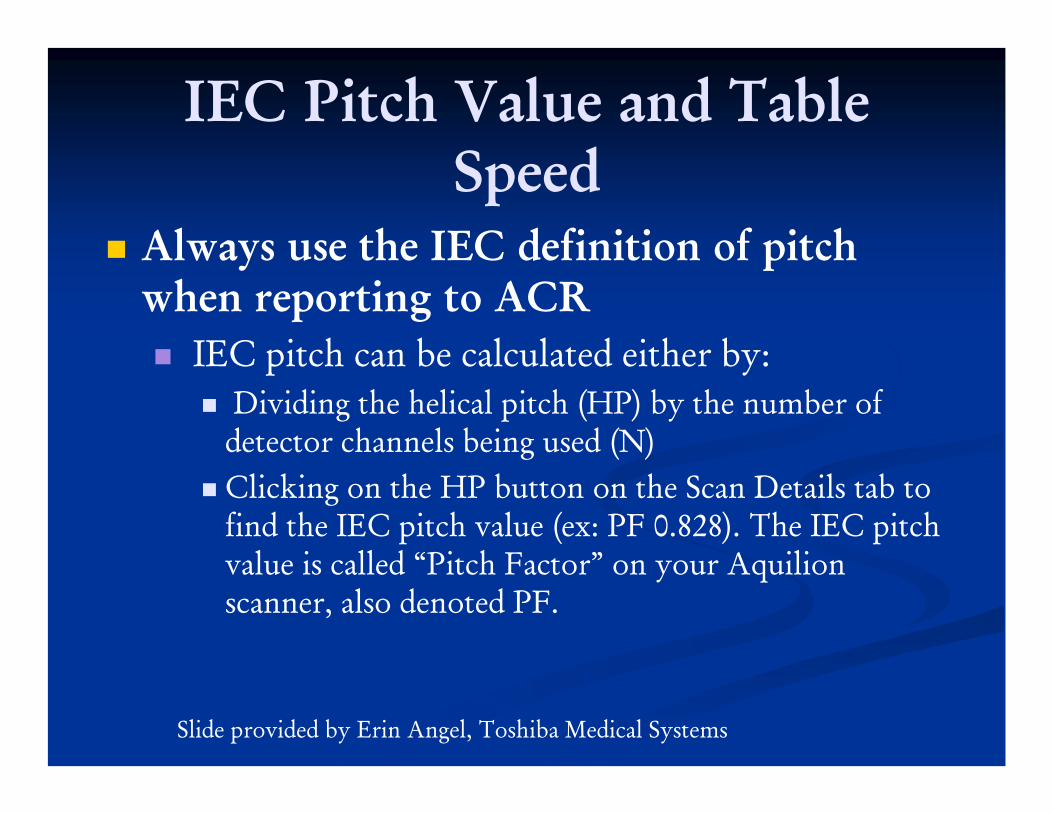
IEC Pitch Value and Table Speed
Always use the IEC definition of pitch when reporting to ACR
IEC pitch can be calculated either by:Dividing the helical pitch (HP) by the number of
detector channels being used (N)Clicking on the HP button on the Scan Details tab to find the IEC pitch value (ex: PF 0.828). The IEC pitch value is called “Pitch Factor” on your Aquilion scanner, also denoted PF.
Slide provided by Erin Angel, Toshiba Medical Systems

IEC Pitch Value and Table Speed
Slide provided by Erin Angel, Toshiba Medical Systems

IEC Pitch Values and Table Speed
Detailed PitchRow Helical Pitch (HP) IEC Pitch Factor16 11 0.688 32 21 0.656 64 41 0.641
Slide provided by Erin Angel, Toshiba Medical Systems

IEC Pitch Values and Table Speed
Standard PitchRow Helical Pitch (HP) IEC Pitch Factor16 15 0.9375 32 27 0.84375 64 53 0.828
Fast PitchRowHelical Pitch (HP)IEC Pitch Factor (PF)16231.437532451.4062564951.484
Slide provided by Erin Angel, Toshiba Medical Systems

IEC Pitch Values and Table Speed
Fast PitchRow Helical Pitch (HP) IEC Pitch Factor16 23 1.4375 32 45 1.40625 64 95 1.484
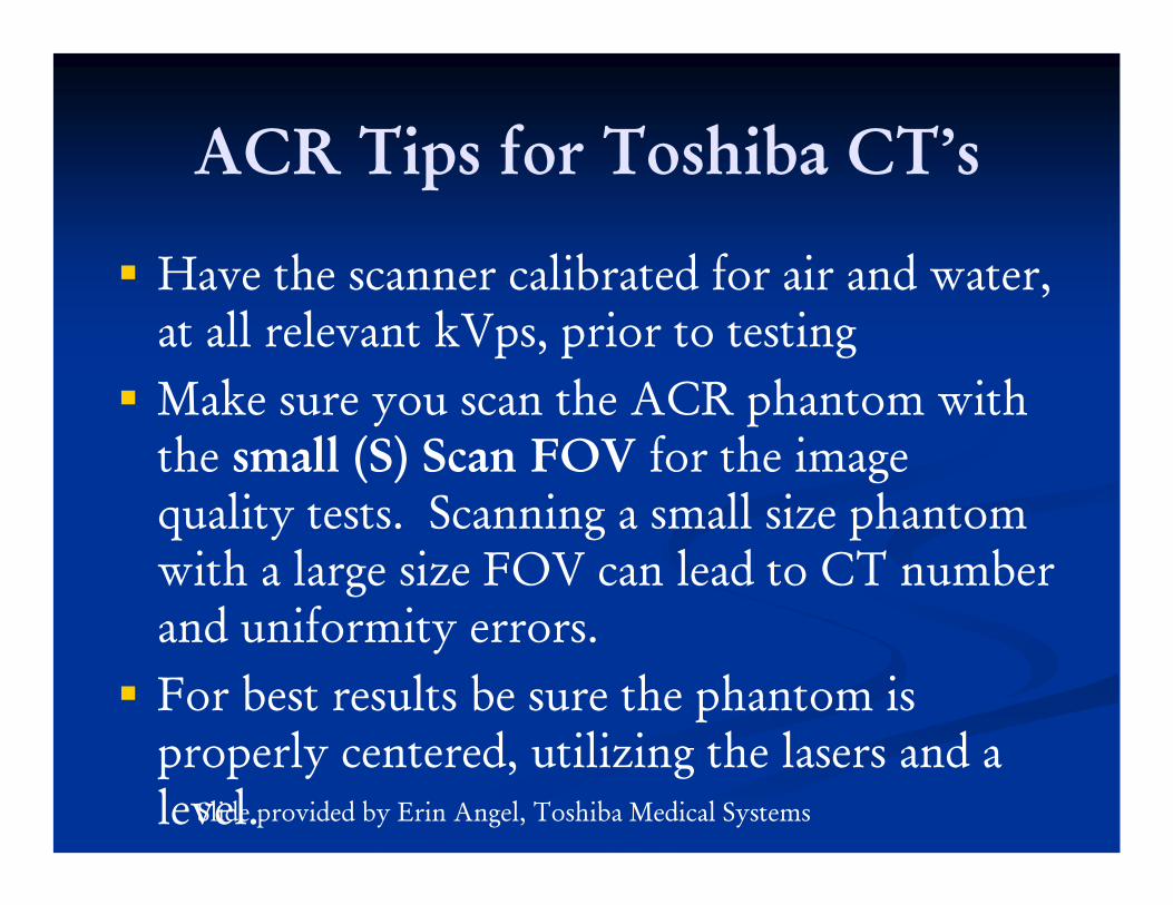
ACR Tips for Toshiba CT’s
Have the scanner calibrated for air and water, at all relevant kVps, prior to testing Make sure you scan the ACR phantom with the small (S) Scan FOV for the image quality tests. Scanning a small size phantom with a large size FOV can lead to CT number and uniformity errors.For best results be sure the phantom is properly centered, utilizing the lasers and a level.Slide provided by Erin Angel, Toshiba Medical Systems

ACR Tips for Toshiba CT’s
Have your “Average Clinical Parameters” chart filled out in advance and be certain to scan the phantom with the corresponding parameters. Before proceeding with phantom image quality testing, ensure your protocols are optimized for dose while obtaining adequate image quality and that radiation doses do not exceed ACR guidelines.For proper landmarking, note where the center of the slice will be when you prescribe a scan in axial or helical mode
Slide provided by Erin Angel, Toshiba Medical Systems

Finding the Center Slice LocationAxial Mode: If a scan is prescribed, for example,
from 24mm to 26mm in 4 x 0.5mm axial mode, the center slice location will be as follows:
Slide provided by Erin Angel, Toshiba Medical Systems
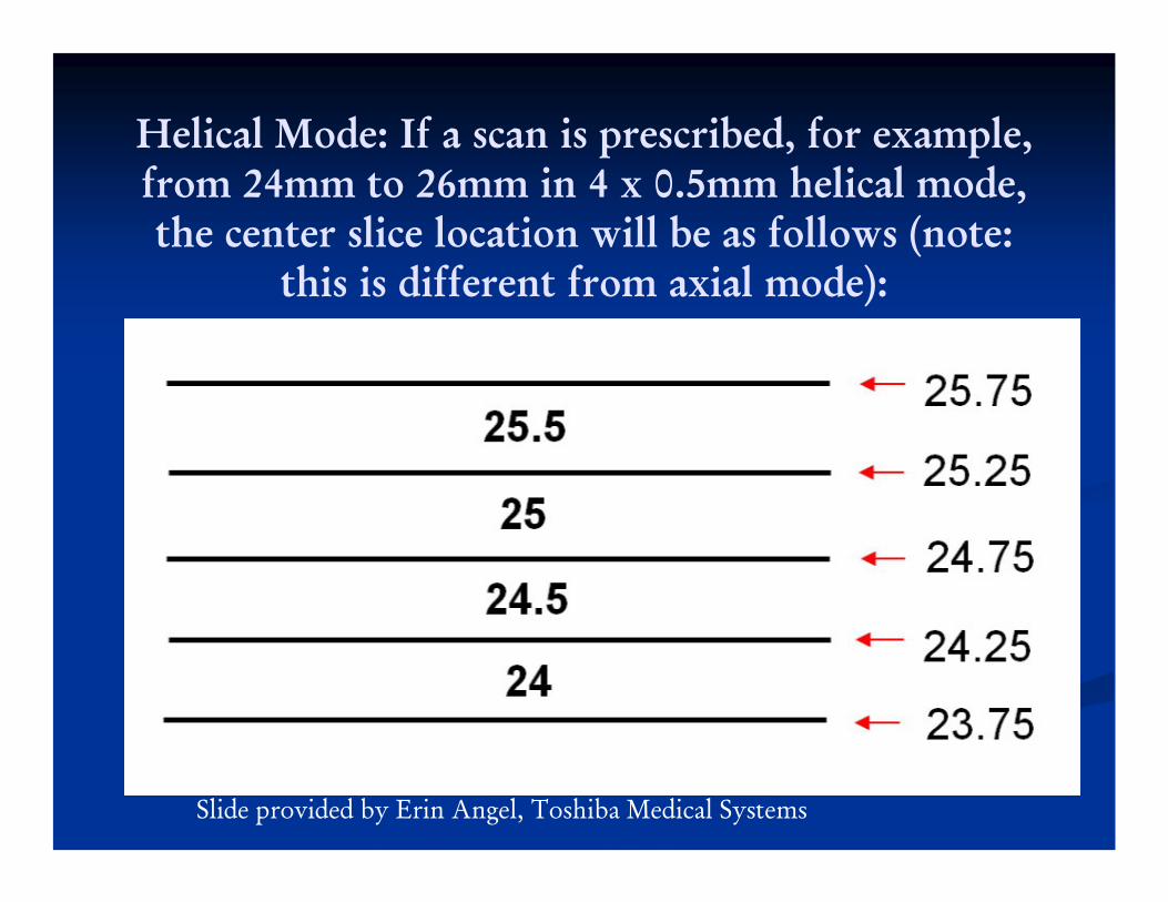
Helical Mode: If a scan is prescribed, for example, from 24mm to 26mm in 4 x 0.5mm helical mode, the center slice location will be as follows (note:
this is different from axial mode):
Slide provided by Erin Angel, Toshiba Medical Systems


Objectives


CONCLUSIONSFor all scanners, make sure that the facility has had service perform preventive maintenance recently.
Review the protocols used with the technologist prior to performing phantom scans and dosimetry.
Contact the vendor help desk for further clarification on a particular scanner.
If at all possible, burn the CD’s for ACR Submission prior to leaving the facility. Do not depend on staff at the facility to correctly burn the CD’s.

Contact Information:
Melissa C. Martin, M.S., FACR, FAAPMTherapy Physics Inc.879 West 190th St., Ste 400Gardena, CA 90248
e-mail: [email protected]: www.TherapyPhysics.com
Phone: 310-612-8127