Embed Size (px)
Citation preview
CES AND GENERAL INFORMATION (Continued) 4
PAMPHLET 5 "Manufacturing Processes Effects on Surface IntegrityN-G. Bellows, D.N. Tishler-GE Co. pamphlet TM70-976, Oct. 1970.
'Surface Integrity Processing Guide Linesv-G. Bellows, D.N. Tishler -GE Go. pamphlet TM70-977, Oct. 1970.
'"elation of Surface Integrity to Cost & Reliability of Structural Components"-W.P. Koster, J.B. Kohls-SME paper 1072-207, April 1972.
"Acceptability Limits for Surface Integrityu-GE Co. Specification P29TF2561, April 14, 1972.
"Electrochemical Machiningr'-J.R. Cross, et al, AFML-TR-72-- September 1972. Contt-act no. F33615-71 -C-1149.
'% Review of Measuring Methods for Surface Integrityu--M. Field, J. Kahles, J. Carnmert-CI RIP presentation, Sept. 1972.
"GI RP Journal" -- Vol. 2012 - page 161, 1971.
'Wachining Data Handbookr'-1972; Machinability Data Center, Metcut Research Assoe.
FURTHER INFORMATION
1. Machinabiliry Data Center (MDC), 3980 Rosslyn Dr., Cincinnati, Ohio 45209. Phone (513) 271-9510, Supervisor technical inquiries.
2. Guy Bellows; Sr. Mfg. Engr. Mfg. Technology Lab, Evendale Plant, Mail Drop N146, GE Co., Cincinnati, Ohio 45215. Phone (513) 243-4976 or dial comm. 8-332-4976.
3. Allan F. Anderson; Mgr., Materials Testing-Materials & Processes Technology Lab, Evendale Plant, Mail Drop M87, GE Co., Cincin- nati, Ohio 45215. Phone (513) 243-4507 or dial comm. 8-332-4507.
4. Dr. Wm. P. Ksster; Vice President, Metcut Research Assoc., Inc., 3980 Rosslyn Dr., Cincinnati, Ohio 45209. Phone (513) 271-5100.
5. B.O. Anderson; Group Supervisor, Mfg. R&D; Commercial Airplane Div.-The Boeing Co., Seattle, Washington, 98124. Phone (513) 931 -2028.
Guy Bellows - Senior Manudacturtaz General Electric Company
Dr. William O. Koster - Vice President Metcut Research Associates
July 1972
AIRCRAFT ENGINE GROUP - GENERAL ELECTRIC COMPANY CINCINNATI, OHIO 4
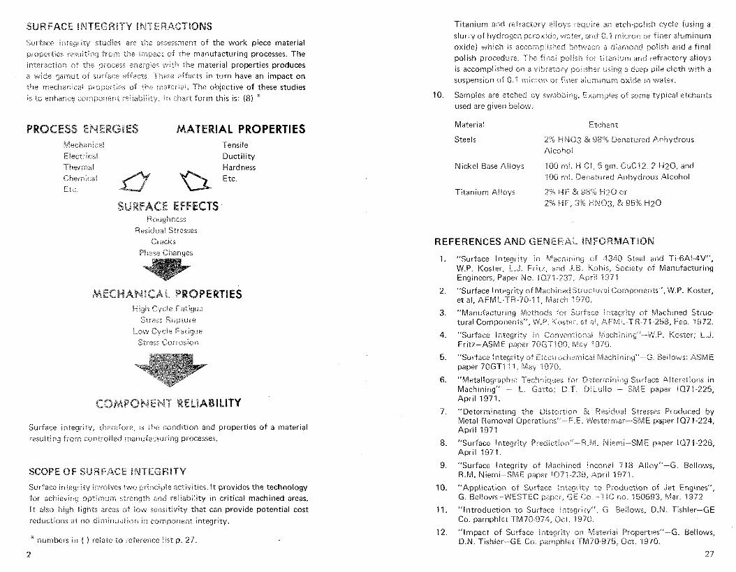
Surface inhegrhy sttrdies are the asssssrnent of the work piece material properties resui7ing -from !he impact of rhe manufacturing processes. The interaction of rhe process ensrgies $with rhe material properties produces a wide gamut of surface e-lf'~cis. These effects in turn have an impact on the meckanicai properties GF the maleria!. The objective of these studies i s to enhance mrnponent :eIEabilEty. in chart form this is: (8) *
IAL PROPERTIES Mechan~cai Tensile Elecrvca! Ductility Thermal Hardness Chemicai Etc. Etc.
E Roughness
Resrdual Stresses Crac~s
Phase Chanaes
High Cycle Fatigue Stress Rupture
Low Cyde Fatigue Stress Cor ro~ io r r
Surface integrity, therefore, is rhe condition and properties of a material resulting from coniiolied rnanufacturlng processes.
Surface integrity involves two principle activities. It provides the technology for achieving optimum strength and rekiabihity in critical machined areas. It also high iights areas of low sensitivity that can provide potential cost reductions at no diminuaiion in component integrity.
* numbers in ( ) relate to reference l i s t p. 27.
2
Titanium and refractory aiioys require an etch-polish cycle (using a
slurry of hydrogen peroxide, water, and 0.1 micron or .finer ali~minum oxide) which is accornpilsked be"v?iem a dlammd poikh and a final polish procedul-e. The final poilsh .For titanium and refractory alioys is accomplished an a vibratory poiisher using a deep pile cloth with a
suspension of 0.1 microrr or finer aitirnincirn oxide i n water.
10. Samples are etched by swabbing. Examp!es of some typical etchants used are given below:
Material Etchsnt
Steels 2% HN03 & 98% Denatured Anhydrous Alcohol
Nickel Base Alloys 100 mi, H GI, 5 gm. CuC12.2 H 2 0 , and 100 ml. Denatured Anhydrous Alcohol
Titanium A!loys 2% HF & 98% )-120 or 2% HF, 3% H N O j , & 95%
REFERENCES ARB
"Surface Integrity in Machining of 4340 Steel and Ti-6AI-4V", W.P. Koster, L.J. Fritz, and J.B. Kohis, Society of Manufacturing Engineers, Paper i2o. i Q71-237, April 1971.
"Surface Integrity of Machined Structural Components", W.P. Koster, e t al, AFM k-TR-78-11, March 1970.
"Manufacturing Methods for Surface ictegrity of hlachined Struc- tural Components", W.P. Koster, et a!, AFIML-TR-71-158, Feb. 1972.
"Surface Integrity in Conventional iliiachiniivf-W.P. Koster; L.J. Fritz-ASME paper 7062-1 68, Ma)i 1978.
"Surface i nkgi-ity of Electrochemica! Machining'"-G, BeBIows: ASM E paper 7CiGT'i 1 1, May 197721.
"Metal!ographic Techr?Iqsses Car Ce;ermlning Surface Alterations in Machining" - L. Gatto; D.T. DieuiEo - SME paper 1671-225, April 197 1.
"Determinating the Distcsriion & Residual Stresses Produced by Metal Removal Operationsw-KE. iliesterman-SME paper 1071-224, April 1971.
"Surface integrity Predictionu-R.itji. Niemi-SME paper 19271-226, April 1971.
"Surface integrity of Machined lrrconel '718 Alloyu-6. Bellows, R.M. Niemi-SME paper 1031-239, Aprii 1971.
"Application of Surface integrity to Production of Jet Engines", G. Bellows-WESTEC paper, GE Co.-TIC no. 150593, Mar. 1972.
"Introduction to Surface lnteyri ty", 6. Reilows, D.N. 'bishler-GE Co. pamphlet TM7O-974, Oct. 9970.
"Impact of Surface lntegriw on Materia: Propertiesu-6. Bellows, D.N. Tishler-GE Co. pamphlet TM70-975, Gct. 1970.
27

APPENDIX TABLE IV BENEFITS OF SURFAC
Mounting Technique and Metallographic Preparation for Edge Retention The desciplined use of surface integrity practices only on those highly stressed or otherwise critical surfaces can yield significant benefits. Among
1. Samples are sectioned from the workpiece in a manner which leads these are:
to the least possible distortion or burring. Bandsawing or hack- sawing is preferred. A minimum of .030 in. is then removed from the cut surface using a 120 grit silicon carbide paper on a low speed polisher.
2. Copper molds (or tubes), 1-1/4 in. inside diameter by 2-314 in. high,
are placed on a pallet approximately 5 in. in diameter. The inner surface of the molds and surface of the pallet are previously sprayed with a silicone releasing agent.
3. After placing a metallurgical specimen in a mold, a mixture of epoxy resin, hardener, and pelletized aluminum oxide, sufficient to produce a layer of 1/4 to 3/13 in. in dep-th, is poured over the specimen. The ratio of resin to hardener is 4 to I . The amount of pellets added is in the range of 10-15 grams. The hardness or abrasive level of the pelletized material used (low, medium, or high fired) i s strictly a function of the alloy to be prepared and its hardness characteristics.
4= I!ne pallet containing the molds is placed in a vacuum chamber (at a vacuum of 4 x 10⁻² to 1 x 10⁻³ torr) in order to degas the mixture, thereby improving the adherence of the epoxy and pellets to the surface of the specimen. When vigorous bubbling of the mixture decreases after vacuum impregnation, sufficient resin and hardener (4 to 1 ratio) is added to produce a mount approximately 1 in. high.
5. The mounts are cured at a temperature not greater than 7 0 ' ~ for approximately 10 hours. Casting of the mounts is accomplished during the latter portion of the laboratory workday, so that curing occurs over night.
6. After curing, they are placed in an oven at a temperature of 1 5 0 ' ~ for a period of one hour, after which they are removed from the molds.
7. Approximately .020 in. of stock i s then removed from the as- mounted metal surface on a positive positioning automatic polishing unit, using the side of a 1 in. by 1 in, by 13 in. aluminum oxide 320 grit grinding wheel as the grinding medium. Water is used as a coolant.
8. Subsequent rough grinding is performed wet on silicon carbide papers or equivalent ranging from 240 to 600 grit.
9. For steels, and nickel and cobalt base superalloys, the intermediate polish is performed on an automatic polisher using a polishing cloth with a soft nap texture and 6 micron diamond paste. The final polish i s achieved using deep nap or pile cloth similar to billiard cloth with a suspension of 0.1 micron or finer aluminum oxide in water.
2 6
Enchanced component integrity.
Cost reduction by use on critical surfaces and relaxation elsewhere
Reduced rework and scrap.
Improved quality assurance.
Enhanced producibiiity data.
Strengthened value analysis.
Defined manufacturing leeways.
Improved understanding of processes and the contra! limits.
Disciplined process selection.
A quick first impression can leave a reaction that the application of
surface integrity will have an adverse affect on production cost. The data coilected to date does indicate that slower, n70i.e gentle process para- meters are essential for the hest surfaces. However, when surface integrity is applied only to those surfaces rhat need extra care, i t h igh i igh i s the possibilities for more re!axed requirements an the remaining surface of a component. The net affect is frequentiy a cost rductior; but in even? case an improvement in product reliability. The potentia! For solving or process failure analysis i s also high. A pair of examples follows. First, a grinding problem:
in the grinding of nickel base alloys, three turbine engine manufacturers have experienced very similar probkms. The first of the group was having difficulty grinding a relatively' small turbine blade from a cast nickel base alloy. The rejection rate clue to mvgio indications after grinding was approximately 60%. Following a subseql~ent five-hour green run of the assembled engine, two-thirds of those blades which had been previously accepted were found to be cracked, again as judged by zygfo inspection. This made for a gross scrap rejection rate of approximateiy 90%, when comparing the numbers of castings going into the machining processes with the number. of blade castings which were acceptabie after engine green run. In examining the blades metaliograpkicai!)i and also From reviewing the grinding processes used, i t was evidenced that the grinding process used was abusive to this particular alloy, although it was quite conventional insofar as standard grinding of medium?-hard materials i s concerned. Limitations to the production equipment would not pecmit a complete conversion to nominai gentie grinding conditions. A corn- promise se t of grinding parameters was developed based on surface
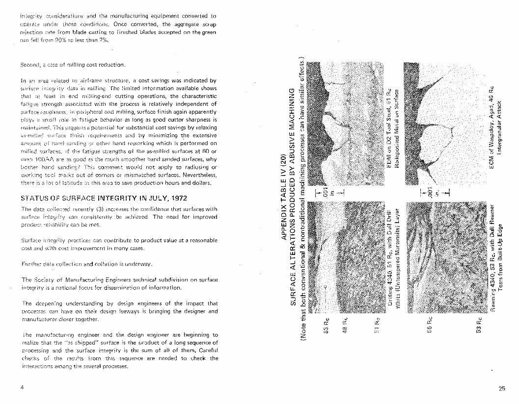
iP*eg~lty cowderatrons and the imanufacturang equipment converted to
oxrate under those conditions. Once converled, the aggregate scrap 5ejec:ron rate from blade castrng to Pinched blades accepted on the green rut? % e l & from 90% to less than 2%
Second, a case of milling cost reduction:
In an area relared to airframe structure, a cost savings was indicated by surface integrity data in miliing. The limited information available shows that 31; least in end rniliing-end cutting operations, the characteristic Fatigue strength associated with the brocess is relatively independent of snriace roughness. In peripheral end milling, surface finish again apparently piays a sn-ail role in fatigue behavior as long as good cutter sharpness i s maintained. This suggests a potential for substantial cost savings by relaxing as-rniiled surface finish requirements and by minimizing the extensive amount of hand sanding or other hand reworking which is performed on rriiiled surfaces. Sf t h e fatigue strengths of rhe as-milled surfaces at 60 or ewers lOOAA are as good as the much sntoother hand sanded surfaces, why bother hand sanding? This comment would not apply to radiusing or !working iooi :marks out of corners or mismatched surfaces. Nevertheless, there is a ?m of iariiude in this area to save production hours and dollars.
STATUS OF
The dara cuilected recently (3 ) increases the confidence that surfaces with swfacr: integrity can consistently be achieved. The need for improved product ~eliabiiity can be met.
Surface 'i.;egrrty practices can contribute to product value at a reasonable cast and w~rh cost Improverrrent in many cases.
Further &la collection and collation is underway.
The Society of Manufacturing Engineers technical subdivision on surface integrity is a .sation& focus for dissemination of information.
The deepe~ing understanding by design engineers of the impact that processes can have on their deskgn iceways 1s bringing the designer and rna~ufacturer closer together.
The manufacturing engineer and the design engineer are beginning to rea!ire that the "as shipped" surface is the product of a long sequence of processing and t he surface integrity is the sum of all of them. Careful checks of the restilts from *.lais sequence are needed to check the interactions among the several processes.
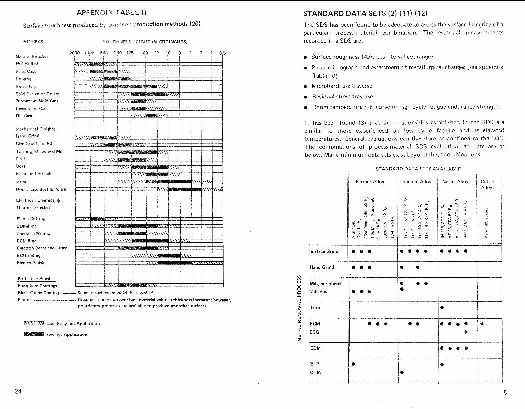
ATA SETS (2) (1 1) (12)
The SDS has been found to be adequate to assess the surface integrity of a particular process-material combination. The essential measui-ements recorded in a SDS are: PROCESS
e Surface roughness (AA, peak to valiey, range)
o Photomicrograph and assessment of rnetallurgicai changes (see appendix
Table IV)
e Microhardness traverse
e Residual stress traverse
e Room temperature S-N curve or high cycle fatigue endurance ztrreng-th.
It has been found (3) that the relationships established in rhe SDS are similar to those experienced on !ow cycle fatigue and a t elevated temperatures. General evaluations can therefore he confined to the SDS, The combinations of wrocess-material SDS eva8~1a.tions to date are as
Mechanical Finishes
Hand Grind
Disc Grind arid File
below. Many minimum data sets exist beyond these combinations
STANDARD DATA SETS AVAILABLE
Il Ferrous Alloys htanium Alloys Nickel Alloys
0 CC ..
Hone, Lap, Buff & Polish
Electrical, Chemical & - Thermal Finishes
Flame CWting
EDMilting
Chsmicai Miiiing
ECMiiEing
Electron Bean and Laser
ECGrinding
Elec?lro Polish Hand Grind I / * @
I1 Mill, peripheral
Mill, end
Pro.tectwe Fmshes
Phosphate Coatings
Black Oxide Coatings - Same as surface on which it is applied.
Plating - Roughness increases over base materia! value as thickness increases; however, prcprietary processes are available to produce smoother surfaces. Turn i I
Less Frequent Application
Average Application
EDM I
ELP
CHM
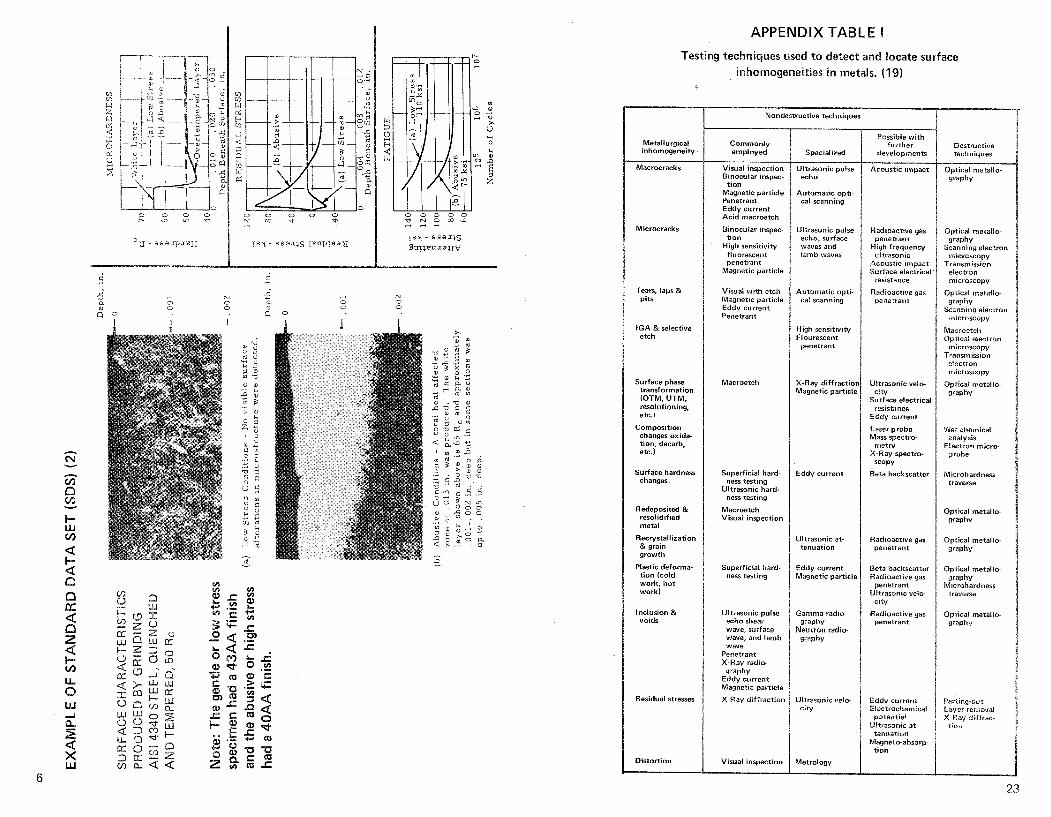
APPENDIX TABLE I
Testing techniques used t o detect and h a t e surface inhomogeneities i n metals. (19)
Metallurgical inhomogeneity
Macrocracks
Microcracks
Tears. laps & pits
I G A & selective etch
Surface phase transformation (OTM, UTM, resolutioniny. etc.)
Composition changes o x i d b tion, decarb, etc.)
Surface hardness changes
Redeposited & resolidified metal
Recrystallization & grain growth
Plastic deforma- t ion (cold work. h o t work)
Inclusion & voids
Residual stresses
Distort ion
Nondestructive technisues
Commonly employed
Visual inspection Binocular inspec-
t i on Magnetic particle Penetrant Eddy current Ac id macroetch
Binocular inspec- t i on
High sensitivity fluorescent penetrant
Magnetic particle
Visual w i th etch Magnetic particle Eddy current Penetrant
Macroetch
Superficial hard- ness testing
Ultrasonic hard- ness testing
Macroetch Visual inspection
Superficial hard- ness testing
Ultvasonic pulse echo shear wave, surface wave, and lamb wave
Penetrant X-Ray radio-
graphy Eddy current Magnetic particle
X-Ray dif fract ion
Visual inspection
Specialized
Ultrasonic pulse echo
Automatic opti- cal scanning
UI:rasonic pulse echo, surface waves iamb waves and
Automatic opti- cal scanning
High sensitivity Flourescent
wenetrant
X-Ray dif fract io Magnetic particlm
Eddv current
Ultrasonic at- tenuation
Eddy current Magnetic par t ic l~
Gamma radio- graphy
Neutron radio- graphy
Uitrasonic velo- c i ty
Metrology
Possible wi th further
developments
Acoustic imwact
Radioactive gas penetrant
High frequency ultrasonic
Acoustic impact Surface elecllricai
resistance
Radioactive gas penetran*
Ultrasonic veic- c i ty
Surface electrical resistance
Eddy current
Laser probe Mass spectro
metry X-Ray spectro-
SCOPV
Beta backscatter
Radioactive gas penetrant
Beta backscatter Radioactive gas
penetrant Ultrasonic velo-
c i ty
Radioactive gas oenetrant
Eddy current Electrochemical
potential Ultrasonic at-
tenuation Magnetc-absorp-
t i on
Destructive techniques
Optical metallo- v p h v
Opticai metallo- g r a p h
Scanning electron microscopy
Transmission electron
microscopy
Optical rnetallo- grapnv
Scertnmg electron rfticroscopy
Macroetch Optical electron
microscopy Transmission electron
microscopy
Optical metallo graphv
Wet analysis chemical
Electron micro- probe
Microhardness traverse
Optical metallo- yraphy
Optical metallo graphy
Optical metal lo w p h v
Microhardness traverse
Optical metallo- w p h v
Parting-cut Layer reinoval X-Ray Iton diffrac-
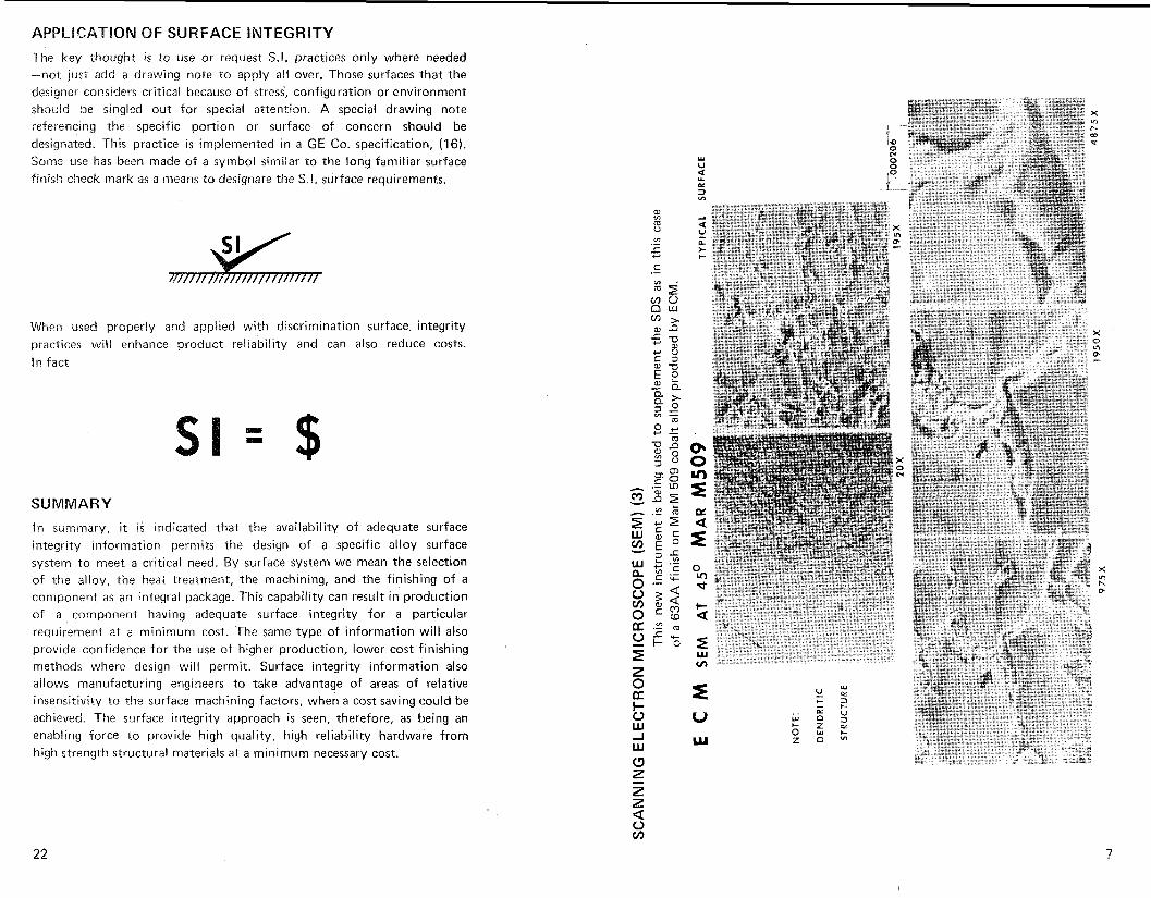
APPLlCAGION QF SURFACE INTEGRITY
The key thought is to use or request S.I. practices only where needed -not just add a drawing note to apply all over. Those surfaces that the designer considers critical because of stress, configuration or environment should be singled out far special attention. A special drawing note referencing the specific portion or surface of concern should be designated. This practice is implemented in a GE Co. specification, (16). Some use has been made of a symbol similar to the long familiar surface finish check mark as a means to designate the S.I. surface requirements.
When used properly and applied with discrimination surface integrity practices will enhance product reliability and can also reduce costs.
In fact
SUMMARY
In summary, it i s indicated that the availability of adequate surface integrity information permits the design of a specific alloy surface system to meet a critical need. By surface system we mean the selection of the alloy, the heat treatment, the machining, and the finishing of a component as an integral package. This capability can result in production of a component having adequate surface integrity for a particular requirement at a minimum cost. The same type of information will also provide confidence for the use of higher production, lower cost finishing methods where design will permit. Surface integrity information also allows manufacturing engineers to take advantage of areas of relative insensitivity to the surface machining factors, when a cost saving could be achieved. The surface integrity approach i s seen, therefore, as being an enabling force to provide high quality, high reliability hardware from high strength structural materials at a minimum necessary cost.
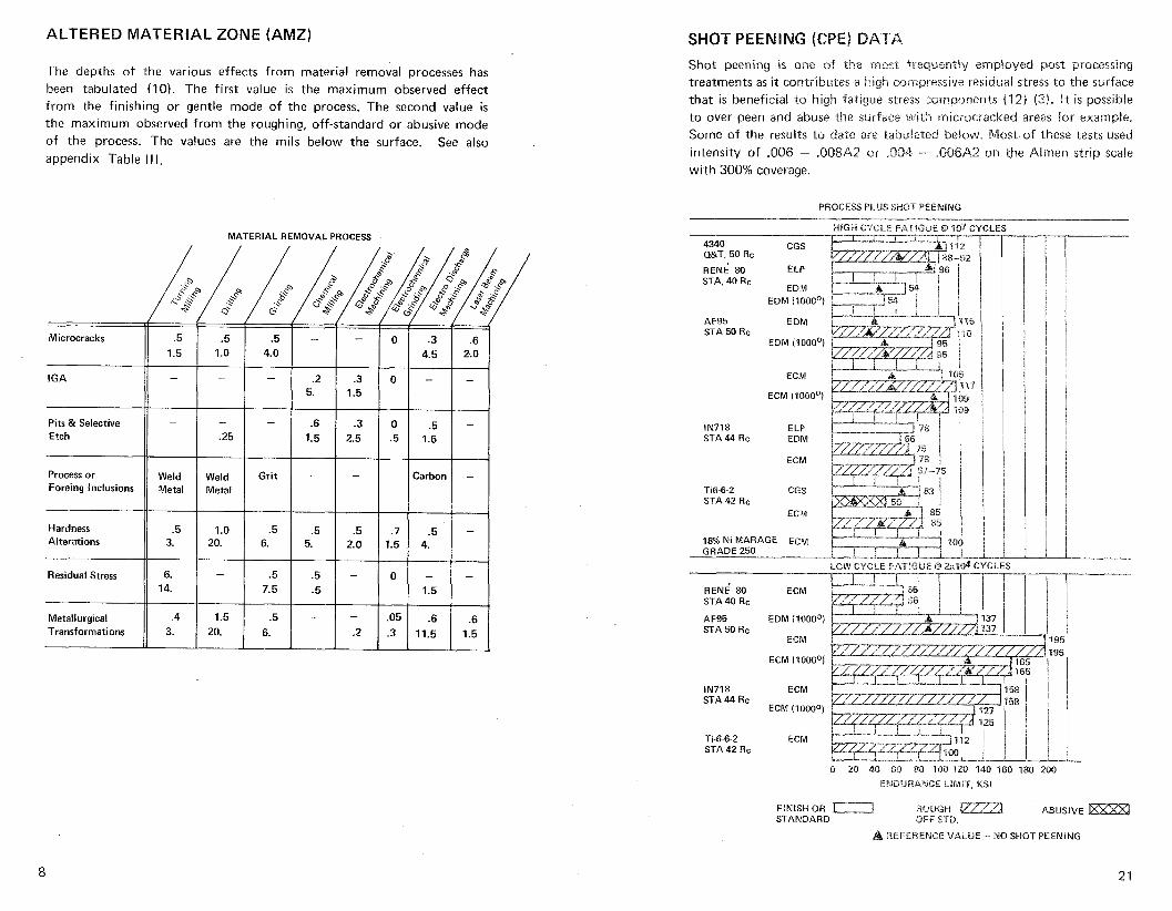
ALTERED MATERIAL ZONE (AMZ) SHOT PEENING (CP
Shot peentng IS one of the rrinsr fteqwen~iy ernpioyed post processing treatments as it contributes a high compressive residual stress to the surface that is beneficial to h ~ g h fatigue stress components (12) 13). It IS poss:ble to over peen and abuse ?-he surface with m~c~ooacked areas for example. Some of the results to date are tabulaxed below. Most of these tests used intensity of ,006 - .8[38A2 or .OD4 - 00QA2 on the Almen strip scale w ~ t h 300% coverage
The depths of the various effects from material removal processes has been tabulated (10). The first value is the maximum observed effect from the finishing or gentle mode of the process. The second value is the maximum observed from the roughing, off-standard or abusive mode of the process. The values are the mils below the surface. See also appendix Table Ill.
PROCESS PLUS SHOT PEEN!NG -
HIGH CYCLE FATdGUE Q 307 CYC MATERIAL REMOVAL PROCESS
Pits & Selective
Process or )( Weld 1 Weld 1 Grit I - 1 - 1 Foreing Inclusions Metal Metal
RENE 80 ELP 96 STA, 40 Rc
EDM EOM (1000°1
AF95 EDM STA 50 Rc
EDM (1000°)
ECM
ECM (1U0O0!
IN718 ELP STA 44 Rc EDM
ECM
Carbon I - Tie-6-2 CGS STA 42 Rc
ECM
Hardness Alterations 18% Ni MARAGE ECM
GRADE 250
, 100 1
LOW CYCLE FATIGUE Q 2x10⁴ 34( Residual Stress
Metallurgical 1.5 Transformations 20.
ECM RENE' 80 STA 40 Rc
AF95 STA 50 Rc
EDM (1000°)
ECiVl
ECM (1000°)
IN718 STA 44 Rc
ECM
ECM (70000)
Ti-6-6-2 STA 42 Rc
ECM
0 20 414 60 80 133 120 140 160 180 200
E M D ~ R A I Y C E IIMr'F, KSI
FINISH OR 1-2 ROUGH ABUSIVE STANDARD OFF STD.
A REFERENCE VALUE - 1\18 SHOT PEENING
TREATMENTS ALTERED MATERIAL ZONE (AMZ) A finishing operation is frequently used to improve or remove the surface layers .from prior processing. While shot peening has been the most exteiisiieiy used post treatment consideration should be given to all var- le tks to achieve the desired effects at the least cost. Some of them are:
AFiM Abrasive Flow Machining CGW Hand Grinding GBN Rolkr Burnishing LSG Low Stress Grinding CBS Beit Sanding HDM Hydrodynamic Machining C!!N Hcr-aing VSR Vibration Stress Relief
CPG happing USP Ultrasonic Peening C P i Shot Peening USC Ultrasonic Cleaning
CPG Elass Eead Peening CWM Chemical Machining
GPO Buffing ELP Electropolish
Ct8 Abrasive Tumbling ECD Electrochemical deburr HT Heat Treatment
No sijigle instrument will measure the relative surface integrity of a surface. Nondes.tructi\~e testing methods currently available have a limited range. The i i s t below are some of those now in use. However, some reliance must be placed on coupon tests and a prime reliance must be placed on carefuily documented process operating parameters and relentless auditing to see that they are maintained. See appendix Table I.
COUPON TESTS
Visual & binocular Optical metallography Sty !us measure of roughness Scanning Electron Microscope Penetrants for macrocracks Microhardness Stain etchants Residual stress distortion X-ray diffraction Magnetic particle Eddy current Uitrasonic Superficial hardness Comparison charts
IBNAL VS. NONTRADITIONAL PROCESSES The original surface integrity investigations concentrated heavily on the suspects - nontraditional material removal processes like EDM and ECM. More recently the older, conventional generally mechanical material removal processes have been shown to have an equal range of S.I. effects. It is vitally important that the application of S.I. practices include an assessmen-t of every process that effects the final, "as shipped" surface.
An AMZ is that zone (s) of a material at the surface and extending inward that has been affected by the processing (1 1). The following definitions were used during the measurements in the preceeding table. For example, the depth of effect from residual stress was taken from the residual stress traverse at the point where the stress had declined to and remained below 20 ksi.
Cracks - a separation, fissure or rupture altering the continuity of a surface, usually narrow or tight and characterized by sharp edges or sharp changes in direction with a depth to width ratio of 4: 1 or greater.
Hardness Alterations - Changes in hardness of a surface layer as a result of heat, plastic deformation or chemical change during processing. (Alterations greater than 2 points Rockwell C (or equivalent) from the bulk of the material were considered significant).
Inclusions - Foreign particles in the material not normal to i t s composition.
Intergranular Attack (IGA) - A form of corrosion or attack in which preferential reactions are concentrated at the surface grain boundaries. These effects are often supplemented by intergranular oxidation (IGO) derived from exposure to elevated temperatures or intergranular corrosion
(IGO) from exposure to active chemical solutions.
Lap, Fold or Seam - A defect from continued plastic working of over- lapping surfaces which do not weld together.
Low Stress Surface - A surface containing a residual stress less than 20 ksi (138 MPa) at depths greater than .001 in. (.026 mm) below the surface. Sometimes called a stress free surface.
Pit - A shallow depression resembling a small crater with rounded edges and less than 4:l depth to width ratio. A specialized form of localized or selective etching or corrosion resulting in holes, or the pockets left by the mechanical removal of small particles from the surface, or the dents from the impingement of foreign particles against the surface.
Plastic Deformation - Microstructure changes due to exceeding the yield point of the material (generally an elongation of grain structure with an increase in hardness).
Redeposited Material - That material, which in the metal removal process, i s removed from the surface in a molten state, and then prior to solidifi- cation is reattached to the surface. (Sometimes called splattered metal).
Remelted or Resolidified Material - That portion of the surface which
during the metal removal process becomes molten, but is not removed from the surface prior to resolidification. (Sometimes called recast).
Selective Etch - A form of in-process corrosion or attack in which preferential reactions are concentrated within and through the grains or concentrated on certain constituents in the base metal.
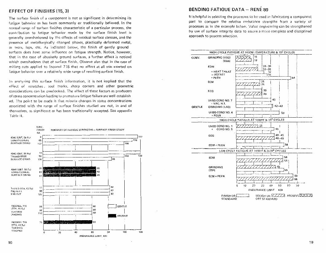
CB OF FINISHES (15,3) It is helpful in selecting the processes to be used in fabricating a component part to compare the relative endurance strengths from a variety of processes as in the example below. Value engineering can be strengthened by use of surface integrity data to assure a more cornpiete and disciplined approach to process selection.
The surface finish of a component i s not as significant in determining i t s fatigue behavior as has been commonly or traditionally believed. In the normal range of surface finishes characteristic of a particular process, the contribution to fatigue behavior made by the surface finish level i s
generally overshadowed by the effects of residual surface stresses, and the presence of metallurgically changed phases, plastically deformed metal, as tears, laps, e.tc. As indicated below, the finish of gently ground surfaces does have some infiuence on fatigue strength. Notice, however, that in the case of abusiveiy ground surfaces, a further effect i s noticed which overshadows that of surface finish. Observe also that in the case of rniiling cuts applied to Bnconel 748 that no effect at all was exerted on fatigue behavior over a relatively wide range of resulting surface finish.
HLGH CYCLE FATIGUE AT ROOM TEMPERATURE & 107 CYCLES
EDM
+ HEAT TREAT - RECAST +PEEN
ECM In analyzing this surface finish information, i t is not implied that the effect of scratches, roo! marks, sharp corners and other geometric considerations can be overlooked. The effect of these factors as producers of stress concentration leading .to premature fatigue failure are well establish- ed. The point to be made is that minute changes in stress concentrations associated with the range of surface finishes studied are not, in and of themselves, as significant as has been traditionally accepted. See appendix
ECG
UHSG-COND NO. 7 + VAC. H.T.
GENTLE GRINDING (LSG)
HIGH CYCLE F4TlGUE AT l20OQF & 107CYCLES I I I r I I I I
Table II.
UHSG-COND NO. 1 + -CONDNO. 5
I I I I
SURF. FINISH SUMMARY OF FATIGUE STRENGTHS -SURFACE FINISH STUDY A A
8 [ 1117 ECG 40-45 4,145 I 1 1 4340 !O&1,55 Rcl
LONGITUDINAL SURFACE GR1ND
EDM + PEEN
LOW CYCLE FATIGUE AT 14000F & 2x10⁴CYCLES - 4340 (Q&T, 50 Rcl TRANSVERSE SURFACE GRlND
GRINDING (750) 55 4340 !Q&T, 50 Rcl
ILONGITUDINAL SURFACE GRIND
ENDtiRANCE LBMK - KSI END MlLL m w CUT
INCONEL 778 (STA, 44 Hc) TURNING (FACING1
INCONEL 718 ISIA. 44 Re) TURNING (FACING)
FINISH OR ROUGH OR ABUSIVE STANDARD OFF STANDARD
25 60 GENT;£
58 60 1 18 60 I I m ABUSIVE
ENDURANCE LIMIT, KSI
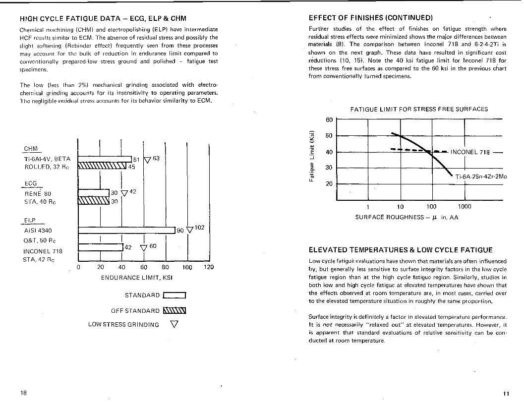
HIGH CYCLE FATIGUE DATA - ECG, ELP & CHM EFFECT OF FINISHES (CONTINUED)
Chemical machining (CHM) and electropolishing (ELP) have intermediate HCF results similar to ECM. The absence of residual stress and possibly the slight softening (Rebinder effect) frequently seen from these processes may account for the bulk of reduction in endurance limit compared to conventionally prepared-low stress ground and polished - fatigue test specimens.
The low (less than 2%) mechanical grinding associated with electro- chemical grinding accounts for i t s insensitivity to operating parameters. The negligible residual stress accounts for i t s behavior similarity to ECM.
CHM
Ti-6AI-4V, BETA ROLLED, 32 Rc
ECG
R E N ~ 80 STA, 40 Rc
INCONEL 718 STA, 42 Rc
0 20 40 60 80 100 120
ENDURANCE LIMIT, KSI
STANDARD L-l
OFF STANDARD b m \ 9 LOW STRESS GRINDING V
Further studies of the effect of finishes on fatigue strength where residual stress effects were minimized shows the major differences between materials (8). The comparison between lnconel 718 and 6-2-4-2Ti i s
shown on the next graph. These data have resulted in significant cost reductions (10, 15). Note the 40 ksi fatigue limit for lnconel 718 for these stress free surfaces as compared to the 60 ksi in the previous chart from conventionally turned specimens.
FATIGUE LIMIT FOR STRESS FREE SURFACES
SURFACE ROUGHNESS - p in. AA
ELEVATED TEMPERATURES & LOW CYCLE FATIGUE
Low cycle fatigue evaluations have shown that materials are often influenced by, but generally less sensitive to surface integrity factors in the low cycle fatigue region than at the high cycle fatigue region. Similarly, studies in both low and high cycle fatigue at elevated temperatures have shown that the effects observed at room temperature are, in most cases, carried over to the elevated temperature situation in roughly the same proportion.
Surface integrity i s definitely a factor in elevated temperature performance. It i s not necessarily "relaxed out" at elevated temperatures. However, it i s apparent that standard evaluations of relative sensitivity can be con- ducted at room temperature.
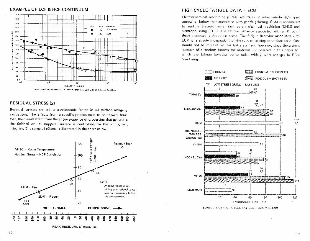
EXAMPLE OF LCF & HCF CONTINUUM 300
280
260
240 LCF HCF Condition
0 EDM & Peen -;; 220
0 EDM h zoo
f 180
q 160 0.
2 140 L
120
: loo 5 E 80
I 60 s 40
20
0
CYCLES TO FAILURE
AF95 - l00O0F Comparison of LCF and HCF Behavior for EDM and EDM & Peened Conditions
RESIDUAL STRESS (2)
Residual stresses are still a considerable factor in all surface integrity evaluations. The effects from a specific process need to be known, how- ever, the overall effect from the entire sequence of processing that generates the finished or "as shipped" surface i s controlling for the component integrity. The range of effects i s illustrated in the chart below.
a m
+-120 Peened (Est.)
I L L .- 0 AF 95 - Room Temperature m Y
Residual Stress - HCF Correlation
,0' / SG
NOTE: On s o m e n icke l a l loys
mi l l ing p e a k residual stress
does n o t necessarily f o l l o w
th is same pat tern .
+ TENSILE I COMPRESSIVE -+
HIGH CYCLE FATIGUE Electrochemica! machining (ECIt'l), resiilts In an intermediate HCF level somewhat below thai associated wi.th gentie grinding. ECM is considered to result in a stress free surface, as are chemical machining (CHLVI) and electropolishing (ELP). The -Fatigue behavior associated with all three of these processes is about the same. The fatigue behavior associated with ECM is relativeiy independent of the rype of cutting corditions used. Qne should not be mislead by this ias t statement, however, sir!ce there are a number of situations known for material not covered in this paper for which the farigue behavior varies auite widely with changes in ECN! processing.
FRONTAL a FRONTAL + SHOT PEEN
SIDE CUT +SHOT PEEN
Ti-6AI-4V
MARASE 100 GRADE 250
MAR M509
SUMMARY OF H1SH CYCLE FATIGUE RESPONSE: ECM
PEAK RESIDUAL STRESS - ksi
LE FAYBGUE DATA - EDM
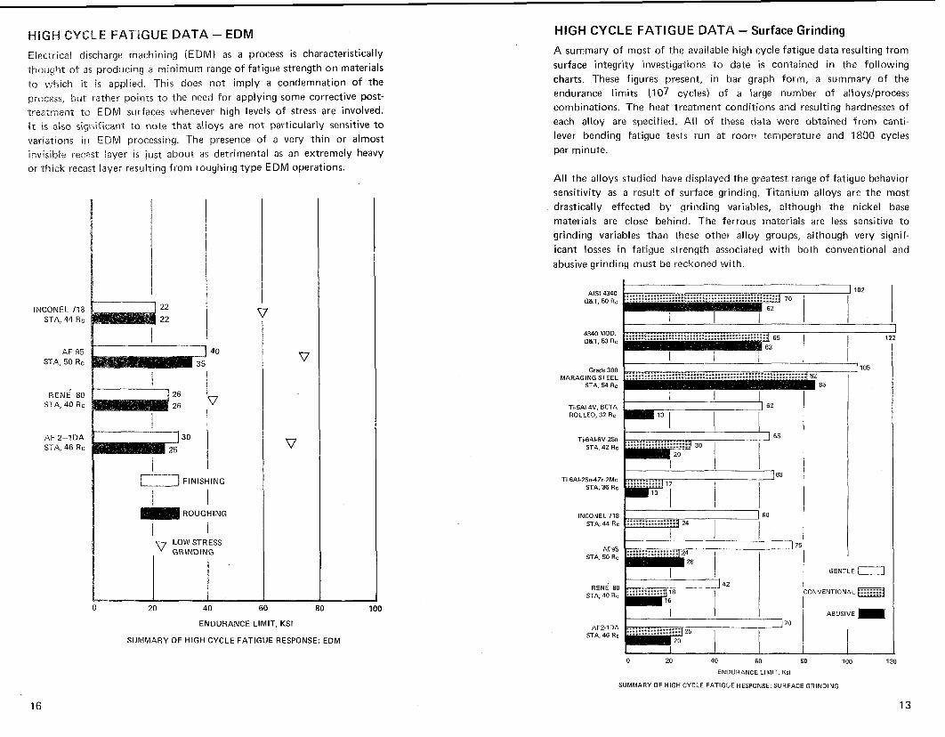
Electrical discharge machining (EDM) as a process is characteristically thought of as producing a minimum range of fatigue strength on materials to which it i s applied. This does not imply a condemnation of the process, but rather points to the need for applying some corrective post- treatment to EDM surfaces whenever high levels of stress are involved. It i s also significant to note that alloys are not particularly sensitive to variations in EDM processing. The presence of a very thin or almost invisible rec;?st layer i s just about as detrimental as an extremely heavy or thick recast layer resulting from roughing type EDM operations.
INCONEL 71E STA, 4 4 Rc
AF 95 STA, 50 Rc
RENE 80 STA, 40 Rc
AF 2-1 DA STA, 46 Rc
b__J FINISHING
ROUGHING
I 1 LOW STRESS
ENDURANCE LIMIT. KSI
SUMMARY OF HlGH CYCLE FATIGUE RESPONSE: €DM
HlGH CYCLE FATIGUE DATA - Surface Grinding
A summary of most of the available high cycle fatigue data resulting from surface integrity investigations to date i s contained in the following charts. These figures present, in bar graph form, a summary of the endurance limits (107 cycles) of a large number of alloys/process combinations. The heat treatment conditions and resulting hardnesses of each alloy are specified. All of these data were obtained from canti- lever bending fatigue tests run at room temperature and 1800 cycles per minute.
All the alloys studied have displayed the greatest range of fatigue behavior sensitivity as a result of surface grinding. Titanium alloys are the most drastically effected by grinding variables, although the nickel base materials are close behind. The ferrous materials are less sensitive to grinding variables than these other alloy groups, although very signif- icant losses in fatigue strength associated with both conventional and abusive grinding must be reckoned with.
Ti-5AI-4V. BETA 62 ROLLED. 32 Rc
Ti-6AI-6V-2Sn 65
STA, 42 Rc
INCONEL 718 STA 44 Rc
AF95 13
STA. 50 Rc I GENTLE
AFZ-IDA STA. 46 Rc ' " I I
0 20 40 60 80 100 120
ENDURANCE LIMIT, Ksi
SUMMARY OF HIGH CYCLE FATIGUE RESPONSE: SURFACE GRINDING
CYCLE FA"TIGLI1 DATA - Hand Grinding
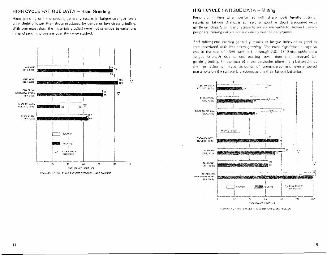
Hand grinding or hand sanding generally results in fatigue strength levels o d y slightly lower than those produced by gentle or low stress grinding. With one exception, the rnateriak studied were not sensitive to variations in hand sanding processes over the range studied.
4340 MOD. 105 r n T , 53 Rc '05
1 GRADE 300 1 I
MARAGING STEEL STA. 54 Rc
Ti-6AI-4V. BETA ROLLED, 32 Rc P
a GENTLE
1 I I
ABUSIVE
I LOWSTRESS GRINDING
j 0 20 40 60 80 100 120
ENDURANCE LIMIT, KSI
SUMMARY OF HIGH CYCLE FATIGUE RESPONSE: HAND SANDING
HIGH CYCLE FATIGUE
Peripheral milling when performed with sharp tools (gentle curring) results in fatigue strengths ar least as good as those associated with gentle grinding. Significant fatigue losses ace eiccauntered, however, when peripheral milling cutters are aIlo\rued to lase their sharpness.
End miiiing-end crj~iing geneiaiay resuirs in fatigue behavior as good as that associated with low stress grinding. The most significant exception was in the case of 4340 modified, al$l-tsugh AISB 4340 aiso exkbited a fatigue strength due :a end cut f tng iower -than that observed for gentle grinding. in the s a s s of rhese par-cisnta: alloys, i t is believed that the formation of trace arnoljnts of unternpered and overtempered martensite on the surface is predominant in their fatigue behavior
TI-6AI 4V. BETA I
ROLLED, 32 Rc 64 i 1 I I
Ti-6AI-GV-2Sn STA, 42 Rc
I i I Ti-6Al-2Sn-4Zr-2Mo 82
STA, 36 8 c
Ti-681-4V. BETA i ROLLED, 32 Rc 77
k 4340 MOD. 63 i Q&T. 50 Rc
63 I 1
MARAGING STEEL
I I ABiiSiVE LOWSTRESS i
t GRlNDIRiG ! 1 I
-A 3 23 40 6L1 83 i 50 r ao
ENDUR?.NCE LiMIT, MSI
SUMMARY OF HIGH CYCLE FATIGUE RESPONSE: END MILLING