Embed Size (px)
Citation preview
21 - 34
TRANSMISSION AND TRANSFER CASE
MANUAL TRANSMISSION
GENERAL INFORMATIONAX15 MANUAL TRANSMISSION . . . . . . . . . . . . . 34TRANSMISSION ASSEMBLY INFORMATION . . . 35TRANSMISSION GEAR RATIOS . . . . . . . . . . . . . 35TRANSMISSION IDENTIFICATION . . . . . . . . . . . 34TRANSMISSION LUBRICANT . . . . . . . . . . . . . . . 35TRANSMISSION SHIFT PATTERN . . . . . . . . . . . 35TRANSMISSION SWITCH AND PLUGLOCATIONS . . . . . . . . . . . . . . . . . . . . . . . . . . 35
DIAGNOSIS AND TESTINGHARD SHIFTING . . . . . . . . . . . . . . . . . . . . . . . . 36LOW LUBRICANT LEVEL . . . . . . . . . . . . . . . . . . 36TRANSMISSION NOISE . . . . . . . . . . . . . . . . . . . 36
REMOVAL AND INSTALLATIONTRANSMISSION . . . . . . . . . . . . . . . . . . . . . . . . . 36
GENERAL INFORMATION
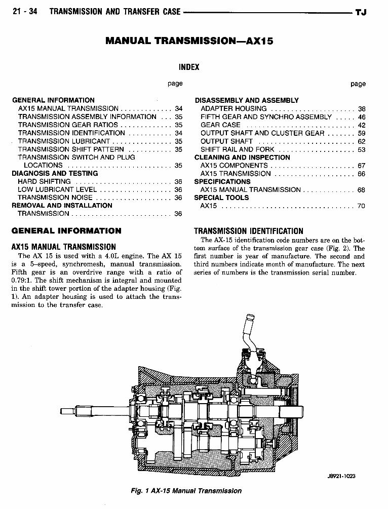
AX15 MANUAL TRANSMISSIONThe AX 15 is used with a 4.OL engine . The AX 15
is a 5-speed, synchromesh, manual transmission .Fifth gear is an overdrive range with a ratio of0 .79:1 . The shift mechanism is integral and mountedin the shift tower portion of the adapter housing (Fig .1) . An adapter housing is used to attach the trans-mission to the transfer case .
INDEX
page
Fig. 1 AX-15 Manual Transmission
AX15
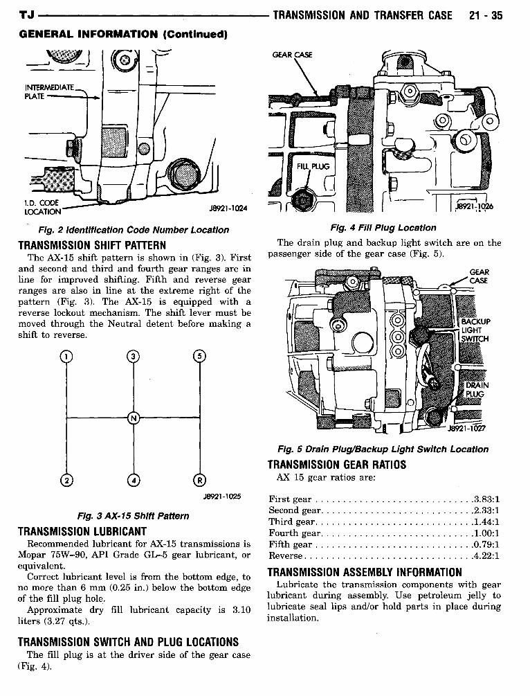
TRANSMISSION IDENTIFICATIONThe AX-15 identification code numbers are on the bot-
tom surface of the transmission gear case (Fig. 2) . Thefirst number is year of manufacture. The second andthird numbers indicate month of manufacture. The nextseries of numbers is the transmission serial number.
J8921-1023
TJ
page
DISASSEMBLY AND ASSEMBLYADAPTER HOUSING . . . . . . . . . . . . . . . . . . . . . 38FIFTH GEAR AND SYNCHRO ASSEMBLY . . . . . 46GEAR CASE . . . . . . . . . . . . . . . . . . . . . . . . . . . 42OUTPUT SHAFT AND CLUSTER GEAR . . . . . . . 59OUTPUT SHAFT
. . . . . . . . . . . . . . . . . . . . . . . . 62SHIFT RAIL AND FORK
. . . . . . . . . . . . . . . . . . . 53CLEANING AND INSPECTIONAX15 COMPONENTS . . . . . . . . . . . . . . . . . . . . . 67AX15 TRANSMISSION . . . . . . . . . . . . . . . . . . . . 66
SPECIFICATIONSAX15 MANUAL TRANSMISSION . . . . . . . . . . . . . 68
SPECIAL TOOLSAX15 . . . . . . . . . . . . . . . . . . . . . . . . . . . . . . . . . 70
TJ
GENERAL INFORMATION (Continued)
Fig. 2 Identification Code Number Location
TRANSMISSION SHIFT PATTERNThe AX-15 shift pattern is shown in (Fig. 3) . First
and second and third and fourth gear ranges are inline for improved shifting. Fifth and reverse gearranges are also in line at the extreme right of thepattern (Fig. 3) . The AX-15 is equipped with areverse lockout mechanism. The shift lever must bemoved through the Neutral detent before making ashift to reverse .
Fig. 3 AX-15 Shift Pattern
J8921-1025
TRANSMISSION LUBRICANTRecommended lubricant for AX-15 transmissions is
Mopar 75W-90, API Grade GL--5 gear lubricant, orequivalent .
Correct lubricant level is from the bottom edge, tono more than 6 mm (0.25 in.) below the bottom edgeof the fill plug hole.Approximate dry fill lubricant capacity is 3.10
liters (3:27 qts .) .
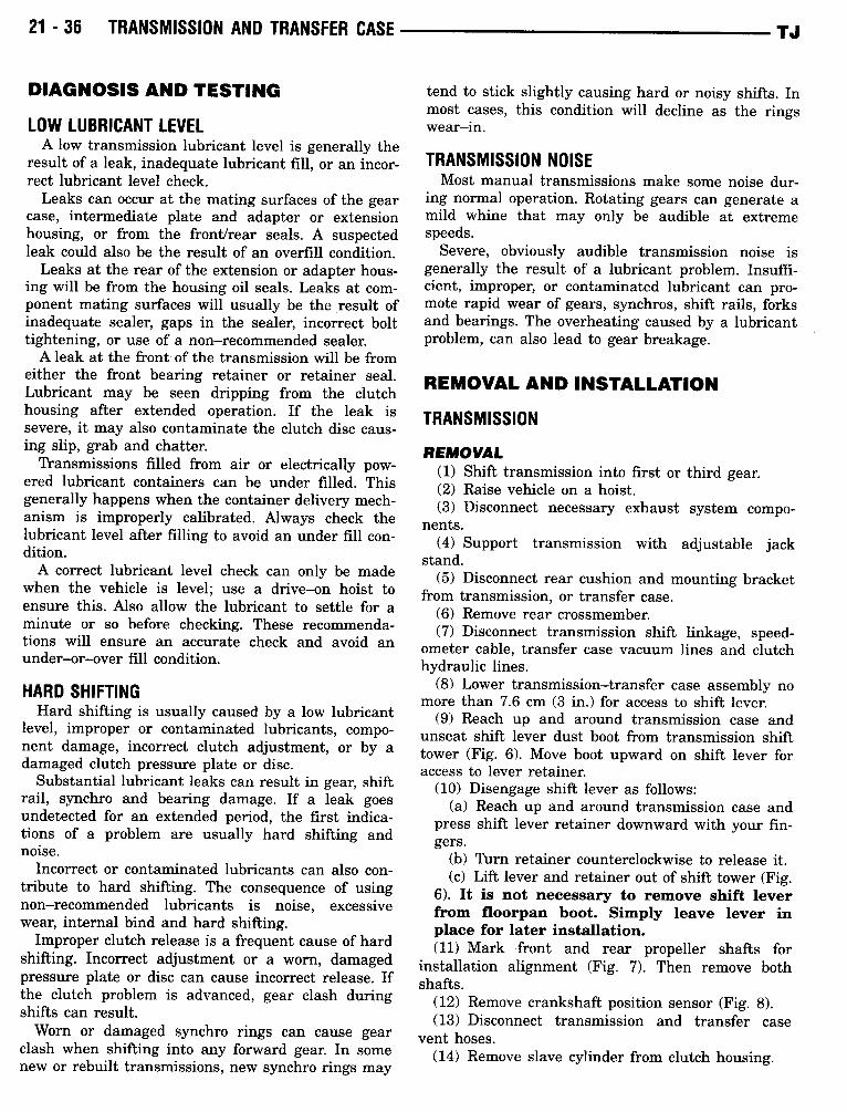
TRANSMISSION SWITCH AND PLUG LOCATIONSThe fill plug is at the driver side of the gear case
(Fig . 4) .
TRANSMISSION AND TRANSFER CASE
21 - 35
GEAR CASE
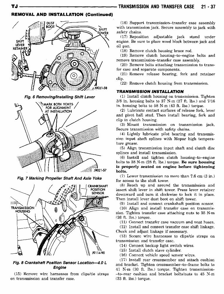
Fig. 4 Fill Plug LocationThe drain plug and backup light switch are on the
passenger side of the gear case (Fig. 5) .
Fig. 5 Drain PluglBackup Light Switch Location
TRANSMISSION GEAR RATIOSAX 15 gear ratios are :
First gear . . . . . . . . . . . . . . . . . . . . . . . . . . . . .3.83:1Second gear . . . . . . . . . . . . . . . . . . . . . . . . . . . .2.33:1Third gear . . . . . . . . . . . . . . . . . . . . . . . . . . . . . 1 .44:1Fourth gear . . . . . . . . . . . . . . . . . . . . . . . . . . . . 1.00:1Fifth gear . . . . . . . . . . . . . . . . . . . . . . . . . . . . .0.79:1Reverse . . . . . . . . . . . . . . . . . . . . . . . . . . . . . . . 4.22:1
TRANSMISSION ASSEMBLY INFORMATIONLubricate the transmission components with gear
lubricant during assembly. Use petroleum jelly tolubricate seal lips and/or hold parts in place duringinstallation .
21 - 36
TRANSMISSION AND TRANSFER CASE
DIAGNOSIS AND TESTING
LOW LUBRICANT LEVELA low transmission lubricant level is generally the
result of a leak, inadequate lubricant fill, or an incor-rect lubricant level check.Leaks can occur at the mating surfaces of the gear
case, intermediate plate and adapter or extensionhousing, or from the front/rear seals . A suspectedleak could also be the result of an overfill condition .Leaks at the rear of the extension or adapter hous-
ing will be from the housing oil seals . Leaks at com-ponent mating surfaces will usually be the result ofinadequate sealer, gaps in the sealer, incorrect bolttightening, or use of a non-recommended sealer.A leak at the front of the transmission will be from
either the front bearing retainer or retainer seal .Lubricant may be seen dripping from the clutchhousing after extended operation . If the leak issevere, it may also contaminate the clutch disc caus-ing slip, grab and chatter.Transmissions filled from air or electrically pow-
ered lubricant containers can be under filled . Thisgenerally happens when the container delivery mech-anism is improperly calibrated . Always check thelubricant level after filling to avoid an under fill con-dition .A correct lubricant level check can only be made
when the vehicle is level ; use a drive-on hoist toensure this . Also allow the lubricant to settle for aminute or so before checking . These recommenda-tions will ensure an accurate check and avoid anunder-or-over fill condition.
HARD SHIFTINGHard shifting is usually caused by a low lubricant
level, improper or contaminated lubricants, compo-nent damage, incorrect clutch adjustment, or by adamaged clutch pressure plate or disc .
Substantial lubricant leaks can result in gear, shiftrail, synchro and bearing damage. If a leak goesundetected for an extended period, the first indica-tions of a problem are usually hard shifting andnoise .
Incorrect or contaminated lubricants can also con-tribute to hard shifting. The consequence of usingnon-recommended lubricants is noise, excessivewear, internal bind and hard shifting.
Improper clutch release is a frequent cause of hardshifting . Incorrect adjustment or a worn, damagedpressure plate or disc can cause incorrect release . Ifthe clutch problem is advanced, gear clash duringshifts can result.Worn or damaged synchro rings can cause gear
clash when shifting into any forward gear. In somenew or rebuilt transmissions, new synchro rings may
TJ
tend to stick slightly causing hard or noisy shifts . Inmost cases, this condition will decline as the ringswear-in .
TRANSMISSION NOISEMost manual transmissions make some noise dur-
ing normal operation. Rotating gears can generate amild whine that may only be audible at extremespeeds .
Severe, obviously audible transmission noise isgenerally the result of a lubricant problem . Insuffi-cient, improper, or contaminated lubricant can pro-mote rapid wear of gears, synchros, shift rails, forksand bearings . The overheating caused by a lubricantproblem, can also lead to gear breakage .
REMOVAL AND INSTALLATION
TRANSMISSION
REMOVAL(1) Shift transmission into first or third gear.(2) Raise vehicle on a hoist .(3) Disconnect necessary exhaust system compo-
nents .(4) Support transmission with adjustable jack
stand .(5) Disconnect rear cushion and mounting bracket
from transmission, or transfer case .(6) Remove rear crossmember.(7) Disconnect transmission shift linkage, speed-
ometer cable, transfer case vacuum lines and clutchhydraulic lines .
(8) Lower transmission-transfer case assembly nomore than 7.6 cm (3 in.) for access to shift lever.
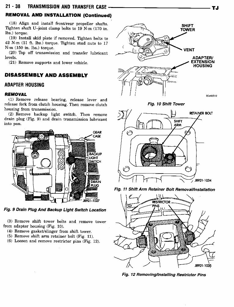
(9) Reach up and around transmission case andunseat shift lever dust boot from transmission shifttower (Fig . 6) . Move boot upward on shift lever foraccess to lever retainer.(10) Disengage shift lever as follows :
(a) Reach up and around transmission case andpress shift lever retainer downward with your fin-gers .
(b) Turn retainer counterclockwise to release it .(c) Lift lever and retainer out of shift tower (Fig .
6) . It is not necessary to remove shift leverfrom floorpan boot. Simply leave lever inplace for later installation.(11) Mark front and rear propeller shafts for
installation alignment (Fig. 7) . Then remove bothshafts .(12) Remove crankshaft position sensor (Fig . 8) .(13) Disconnect transmission and transfer case
vent hoses .(14) Remove slave cylinder from clutch housing .
TJ
REMOVAL AND INSTALLATION (Continued)
Fig. 6 Removing4nstalling Shift Lever
1 MARK BOTH YOKES/\ FOR ALIGNMENT
AT INSTALLATION
TRANSMISSIONHOUSING
19021-57
Fig. 7 Marking Propeller ShaftAnd Axle Yoke
CRANKSHAFTPOSITIONSENSOR
Fig. 8 Crankshaft Position Sensor Location-4.0 LEngine
(15) Remove wire harnesses from clips/tie strapson transmission and transfer case .
TRANSMISSION AND TRANSFER CASE
21 - 37
(16) Support transmission-transfer case assemblywith transmission jack . Secure assembly to jack withsafety chains .
(17) Reposition adjustable jack stand underengine . Be sure to place wood block between jack andoil pan .(18) Remove clutch housing brace rod .(19) Remove clutch housing-to-engine bolts and
remove transmission-transfer case assembly.(20) Remove bolts attaching transmission to trans-
fer case and separate components.(21) Remove release bearing, fork and retainer
clip .(22) Remove clutch housing from transmission .
TRANSMISSION INSTALLATION(1) Install clutch housing on transmission . Tighten
3/8 in . housing bolts to 37 N-m (27 ft. lbs .) and 7/16in. housing bolts to 58 N-m (43 ft. lbs .) torque .
(2) Lubricate contact surfaces of release fork, leverand pivot ball stud. Then install bearing, fork andclip in clutch housing.
(3) Mount transmission on transmission jack .Secure transmission with safety chains .
(4) Lightly lubricate pilot bearing and transmis-sion input shaft splines with Mopar high tempera-ture grease .
(5) Align transmission input shaft and clutch discsplines and install transmission .
(6) Install and tighten clutch housing-to-enginebolts to 38 N-m (28 ft . lbs.) torque . Be sure housingis properly seated on engine before tighteningbolts.
(7) Lower transmission no more than 7 .6 cm (3 in.)for access to the shift tower.
(8) Reach up and around the transmission andinsert shift lever in shift tower. Press lever retainerdownward and turn it clockwise to lock it in place .Then install lever dust boot on shift tower.
(9) Install and connect crankshaft position sensor.(10) Align and install transfer case on transmis-
sion . Tighten transfer case attaching nuts to 35 N-m(26 ft. lbs .) torque .
(11) Connect transfer case vacuum and vent hoses.(12) Install and connect transfer case shift linkage .
Check and adjust linkage if necessary.(13) Secure wire harnesses to clips/tie straps on
transmission and transfer case .(14) Connect backup light switch wires .(15) Install clutch slave cylinder.(16) Connect vehicle speed sensor wires .(17) Install rear crossmember and attach cushion
and bracket . Tighten crossmember-to-frame bolts to41 N-m (30 ft . lbs .) torque . Tighten transmission--to-rear cushion and bracket bolts/nuts to 45 N-m(33 ft . lbs .) torque .
21 -38
TRANSMISSION AND TRANSFER CASE -
REMOVAL AND INSTALLATION (Continued)(18) Align and install front/rear propeller shafts .
Tighten shaft U-joint clamp bolts to 19 N-m (170 in .lbs.) torque .
(19) Install skid plate if removed . Tighten bolts to42 N-m (31 ft . lbs .) torque . Tighten stud nuts to 17N-m (150 in . lbs .) torque .
(20) Top off transmission and transfer lubricantlevels .
(21) Remove supports and lower vehicle .
DISASSEMBLY AND ASSEMBLY
ADAPTER HOUSING
REMOVAL(1) Remove release bearing, release lever and
release fork from clutch housing . Then remove clutchhousing from transmission .
(2) Remove backup light switch . Then removedrain plug (Fig . 9) and drain transmission lubricantinto pan.
Fig. 9 Drain Plug And Backup Light Switch Location
(3) Remove shift tower bolts and remove towerfrom adapter housing (Fig . 10) .
(4) Remove gasket/slinger from shift tower.(5) Remove shift arm retainer bolt (Fig . 11).(6) Loosen and remove restrictor pins (Fig. 12) .
Fig. 10 Shift Tower
SHIFTTOWER
ADAPTER/EXTENSIONHOUSING
60a4d312
Fig. 11 Shift Arm Retainer Bolt RemovallInstallation
Fig. 12 Removingllnstalling Restrictor Pins
TJ
TJ
DISASSEMBLY AND ASSEMBLY (Continued)
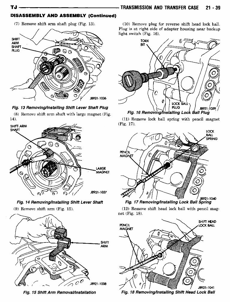
(7) Remove shift arm shaft plug (Fig . 13) .
Fig . 13 Removinglinstalling Shift Lever Shaft Plug
(8) Remove shift arm shaft with large magnet (Fig .14) .
Fig. 14 Removinglnstalling Shift Lever Shaft
(9) Remove shift arm (Fig. 15) .
Fig. 15 Shift Arm Removalllnstallation
TRANSMISSION AND TRANSFER CASE
21-39
(10) Remove plug for reverse shift head lock ball .Plug is at right side of adapter housing near backuplight switch (Fig. 16) .
`
~ LOCK BALLPLUG
) J J8921-1039fFi . 16 Removin
nstallin
Lock Ball Plu9
9
9(11) Remove lock ball spring with pencil magnet
(Fig . 17) .
J8921-1040Fig. 17 Removing4nstalling Lock Ball Spring
(12) Remove shift head lock ball with pencil mag-net (Fig. 18) .
J8921-1041
Fig. 18 Removinglinstalling Shift Head Lock Ball
21 -40
TRANSMISSION AND TRANSFER CASE
TJDISASSEMBLY AND ASSEMBLY (Continued)
ADAPTER/EX'HOUSING BOLTS(RIGHT SIDE)
ADAPTER/EXTENSIONHOUSING BOLTS(LEFT SIDE)
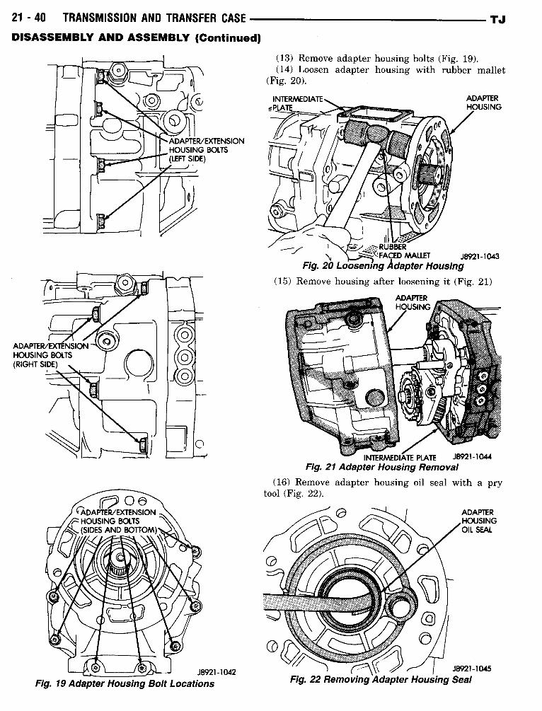
J8921-1042Fig. 19 Adapter Housing Bolt Locations
(13) Remove adapter housing bolts (Fig . 19) .(14) Loosen adapter housing with rubber mallet
(Fig . 20) .
'< cdi
RUBBER~
'-FACED MALLET
J8921-1043Fig. 20 LooseningAdapter Housing
(15) Remove housing after loosening it (Fig . 21)
ADAPTERHOUSING
INTERMEDIATE PLATE
J8921-1044Fig. 21 Adapter Housing Removal
(16) Remove adapter housing oil seal with atool (Fig. 22) .
pry
ADAPTERHOUSINGOIL SEAL
J8921-1045Fig. 22 Removing Adapter Housing Seal
TJ
DISASSEMBLY AND ASSEMBLY (Continued)
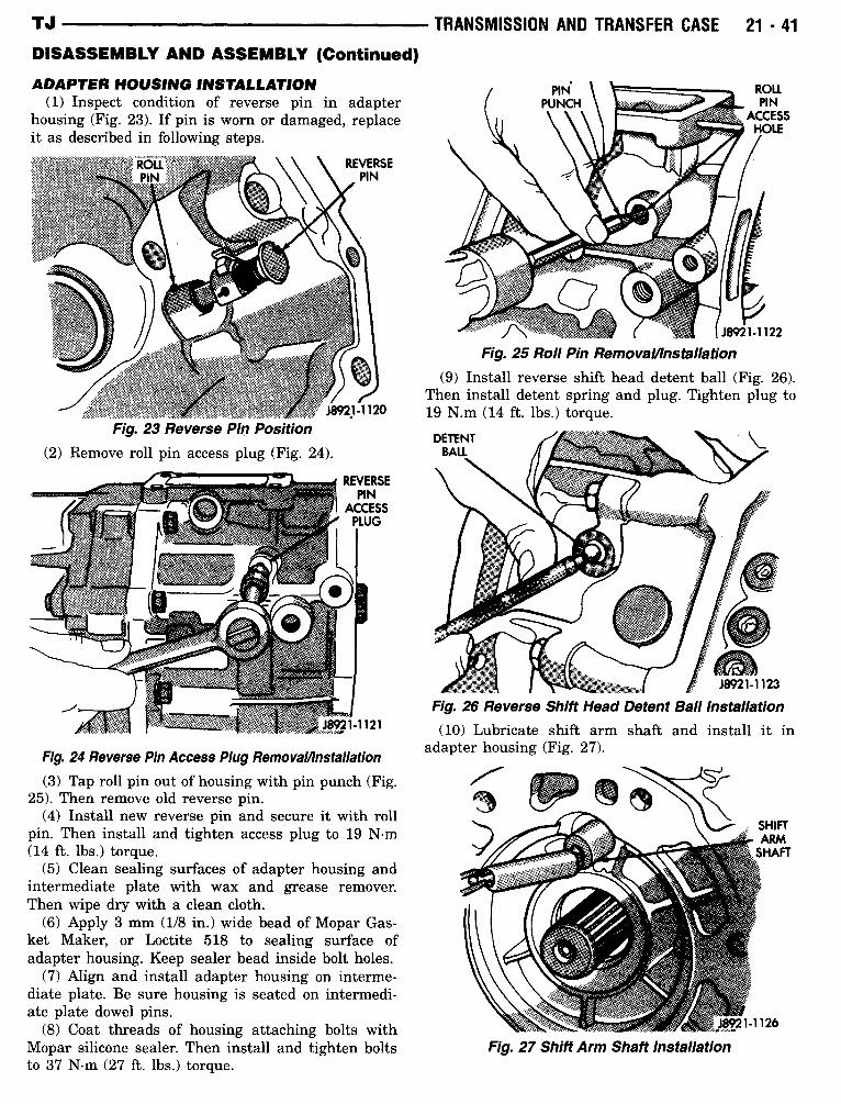
ADAPTER HOUSING INSTALLATION(1) Inspect condition of reverse pin in adapter
housing (Fig . 23) . If pin is worn or damaged, replaceit as described in following steps .
Fig. 23 Reverse Pin Position(2) Remove roll pin access plug (Fig. 24) .
REVERSEPIN
ACCESSPLUG
Fig. 24 Reverse Pin Access Plug RemovaOnstallation(3) Tap roll pin out of housing with pin punch (Fig .
25) . Then remove old reverse pin.(4) Install new reverse pin and secure it with roll
pin. Then install and tighten access plug to 19 N-m(14 ft . lbs .) torque .
(5) Clean sealing surfaces of adapter housing andintermediate plate with wax and grease remover.Then wipe dry with a clean cloth .
(6) Apply 3 mm (1/8 in.) wide bead of Mopar Gas-ket Maker, or Loctite 518 to sealing surface ofadapter housing . Keep sealer bead inside bolt holes .
(7) Align and install adapter housing on interme-diate plate . Be sure housing is seated on intermedi-ate plate dowel pins .
(8) Coat threads of housing attaching bolts withMopar silicone sealer. Then install and tighten boltsto 37 N-m (27 ft . lbs .) torque .
TRANSMISSION AND TRANSFER CASE
21-41
Fig. 25 Roll Pin Removalllnstallation
19 N.m (14 ft . lbs .) torque .
DETENTBALL
Fig. 27 Shift Arm Shaft Installation
(9) Install reverse shift head detent ball (Fig . 26) .Then install detent spring and plug . Tighten plug to
J8921-1123Fig. 26 Reverse Shift Head Detent Ball Installation(10) Lubricate shift arm shaft and install it in
adapter housing (Fig. 27) .
21 -42
TRANSMISSION AND TRANSFER CASEDISASSEMBLY AND ASSEMBLY (Continued)
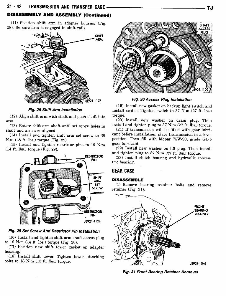
(11) Position shift arm in adapter housing (Fig.28) . Be sure arm is engaged in shift rails .
Fig. 28 Shift Arm Installation(12) Align shift arm with shaft and push shaft into
arm.(13) Rotate shift arm shaft until set screw holes in
shaft and arm are aligned .(14) Install and tighten shift arm set screw to 38
N-m (28 ft . lbs .) torque (Fig. 29) .(15) Install and tighten restrictor pins to 19 N-m
(14 ft . lbs .) torque (Fig. 29).
Fig. 29 Set Screw And Restrictor Pin Installation(16) Install and tighten shift arm shaft access plug
to 19 N-m (14 ft . lbs .) torque (Fig. 30) .(17) Position new shift tower gasket on adapter
housing .(18) Install shift tower. Tighten tower attaching
bolts to 18 N-m (13 ft . lbs.) torque .
(19) Install new gasket on backup light switch andinstall switch . Tighten switch to 37 N-m (27 ft. lbs .)torque .
(20) Install new washer on drain plug. Theninstall and tighten plug to 37 N-m (27 ft. lbs .) torque .
(21) If transmission will be filled with gear lubri-cant before installation, place transmission in a levelposition . Then fill with Mopar 75W-90, grade GL-5gear lubricant .
(22) Install new washer on fill plug. Then installand tighten plug to 37 N-m (27 ft. lbs .) torque .
(23) Install clutch housing and hydraulic concen-tric bearing .
GEAR CASE
Fig. 30 Access Plug Installation
DISASSEMBLE(1) Remove bearing retainer bolts and remove
retainer (Fig. 31) .
Fig . 31 Front Bearing Retainer Removal
TJ
TJ
TRANSMISSION AND TRANSFER CASE
21 -43DISASSEMBLY AND ASSEMBLY (Continued)
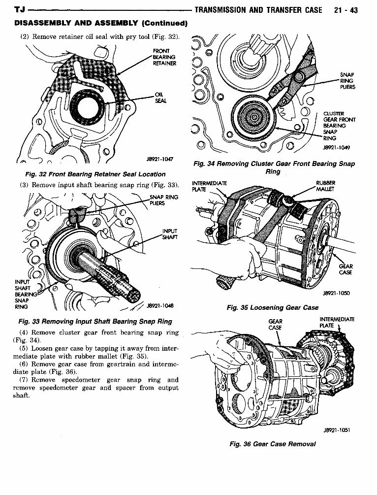
(2) Remove retainer oil seal with pry tool (Fig. 32) .
Fig. 32 Front Bearing Retainer Seal Location(3) Remove input shaft bearing snap ring (Fig . 33) .
i 1
(4) Remove cluster gear front bearing snap ring(Fig . 34) .
(5) Loosen gear case by tapping it away from inter-mediate plate with rubber mallet (Fig. 35) .
(6) Remove gear case from geartrain and interme-diate plate (Fig . 36) .
(7) Remove speedometer gear snap ring andremove speedometer gear and spacer from outputshaft.
Fig. 34 Removing Cluster Gear Front Bearing SnapRing
Fig. 35 Loosening Gear Case
Fig. 33 Removing Input Shaft Bearing Snap Ring
GEAR
INTERMEDIATEd ATV
Fig. 36 Gear Case Removal
J8921-1050
21 -44
TRANSMISSION AND TRANSFER CASEDISASSEMBLY AND ASSEMBLY (Continued)GEAR CASE ASSEMBLE
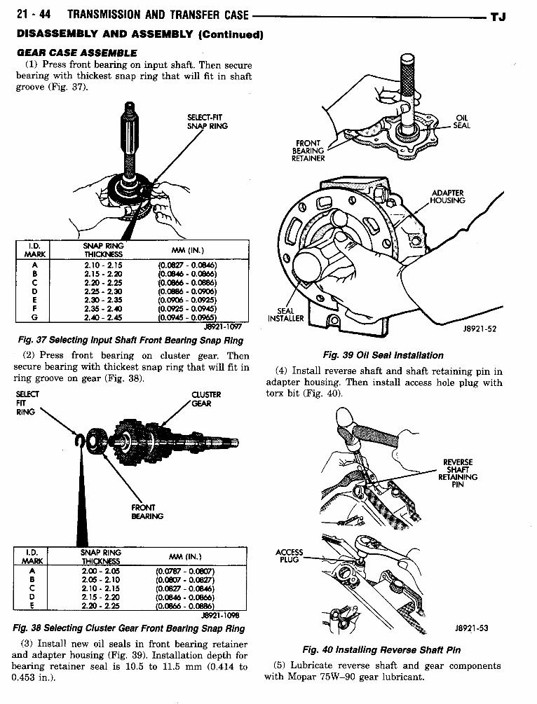
(1) Press front bearing on input shaft . Then securebearing with thickest snap ring that will fit in shaftgroove (Fig . 37) .
J8921-1097
Fig. 37 Selecting Input Shaft Front Bearing Snap Ring
(2) Press front bearing on cluster gear. Thensecure bearing with thickest snap ring that will fit inring groove on gear (Fig. 38) .
J8921-1098
Fig. 38 Selecting Cluster Gear Front Bearing Snap Ring
(3) Install new oil seals in front bearing retainerand adapter housing (Fig . 39) . Installation depth forbearing retainer seal is 10.5 to 11.5 mm (0 .414 to0.453 in.) .
ACCESSPLUG
Fig. 39 Oil Seal Installation
Fig. 40 Installing Reverse Shaft Pin
OILSEAL
REVERSESHAFT
RETAININGPIN
J8921-53
TJ
(4) Install reverse shaft and shaft retaining pin inadapter housing. Then install access hole plug withtorx bit (Fig . 40) .
(5) Lubricate reverse shaft and gear componentswith Mopar 75W-90 gear lubricant .
I .D.MARK
SNAP RINGTHICKNESS MM (IN .)
A 2.10-2.15 (0.0827 - 0.0846)B 2.15-2.20 (0.0846 - 0.0866)C 2.20-2.25 (0.0866 - 0.0886)D 2.25-2.30 (0.0886 - 0.0906)E 2.30- .2 .35 (0.0906 - 0.0925)F 2.35-2.40 (0.0925 - 0.0945)G 2.40-2.45 0.0945 - 0.0965
I.D.MARK
SNAP RINGTHICKNESS MM (IN.)
A 2.00-2.05 (0.0787 - 0.0807)B 2.05-2.10 (0.0807 - 0.0827)C 2.10-2.15 (0.0827 - 0.0846)D 2.15-2.20 (0.0846 - 0.0866)E 2.20-2.25 0.0866 - 0.0886
TJ
DISASSEMBLY AND ASSEMBLY (Continued)
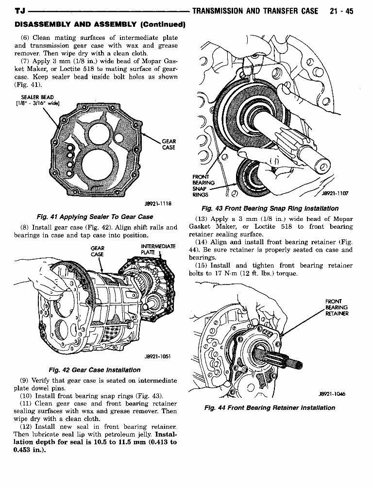
(6) Clean mating surfaces of intermediate plateand transmission gear case with wax and greaseremover. Then wipe dry with a clean cloth .
(7) Apply 3 mm (1/8 in.) wide bead of Mopar Gas-ket Maker, or Loctite 518 to mating surface of gear-case . Keep sealer bead inside bolt holes as shown(Fig. 41) .
Fig. 41 Applying Sealer To Gear Case
GEARCASE
J8921-1118
(8) Install gear case (Fig . 42) . Align shift rails andbearings in case and tap case into position .
Fig. 42 Gear Case Installation(9) Verify that gear case is seated on intermediate
plate dowel pins.(10) Install front bearing snap rings (Fig . 43) .(11) Clean gear case and front bearing retainer
sealing surfaces with wax and grease remover. Thenwipe dry with a clean cloth .
(12) Install new seal in front bearing retainer.Then lubricate seal lip with petroleum jelly. Instal-lation depth for seal is 10.5 to 11.5 mm (0.413 to0.453 in.) .
TRANSMISSION AND TRANSFER CASE
21 -45
Fig. 43 Front Bearing Snap Ring Installation(13) Apply a 3 mm (1/8 in.) wide bead of Mopar
Gasket Maker, or Loctite 518 to front bearingretainer sealing surface .
(14) Align and install front bearing retainer (Fig .44) . Be sure retainer is properly seated on case andbearings .
(15) Install and tighten front bearing retainerbolts to 17 N-m (12 ft. lbs .) torque .
Fig. 44 Front Bearing Retainer Installation
21 -46
TRANSMISSION AND TRANSFER CASE -
DISASSEMBLY AND ASSEMBLY (Continued)
VISEJAWS
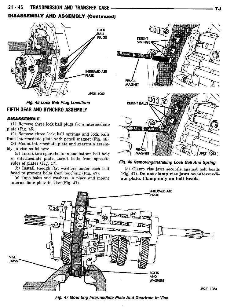
Fig. 45 Lock Ball Plug Locations
FIFTH GEAR AND SYNCHRO ASSEMBLY
DISASSEMBLE(1) Remove three lock ball plugs from intermediate
plate (Fig . 45) .(2) Remove three lock ball springs and lock balls
from intermediate plate with pencil magnet (Fig. 46) .(3) Mount intermediate plate and geartrain assem-
bly in vise as follows :(a) Insert two spare bolts in one bottom bolt hole
in intermediate plate . Insert bolts from oppositesides of plates (Fig . 47) .
(b) Install enough flat washers under each bolthead to prevent bolts from touching (Fig . 47) .
(c) Tape bolts and washers in place and mountintermediate plate in vise (Fig . 47) .
Fig. 46 Removingllnstalling Lock Ball And Spring(d) Clamp vise jaws securely against bolt heads
(Fig. 47) . Do not clamp vise jaws on intermedi-ate plate. Clamp only on bolt heads.
Fig. 47 Mounting Intermediate Plate And Geartrain In Vise
TJ
TJ
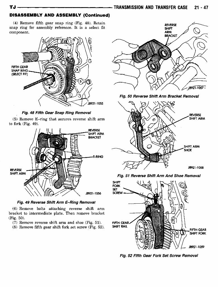
DISASSEMBLY AND ASSEMBLY (Continued)(4) Remove fifth gear snap ring (Fig. 48) . Retain
snap ring for assembly reference . It is a select fitcomponent.
Fig. 48 Fifth Gear Snap Ring Removal
(5) Remove E-ring that secures reverse shift armto fork (Fig. 49) .
Fig. 49 Reverse Shift Arm E-Ring Removal
(6) Remove bolts attaching reverse shift armbracket to intermediate plate . Then remove bracket(Fig . 50) .
(7) Remove reverse shift arm and shoe (Fig . 51) .(8) Remove fifth gear shift fork set screw (Fig. 52) .
TRANSMISSION AND TRANSFER CASE
21 -47
J8921-1057-
Fig. 50 Reverse Shift Arm Bracket Removal
Fig. 51 Reverse ShiftArm And Shoe Removal
Fig. 52 Fifth Gear Fork Set Screw- Removal
21 -48
TRANSMISSION AND TRANSFER CASE -DISASSEMBLY AND ASSEMBLY (Continued)
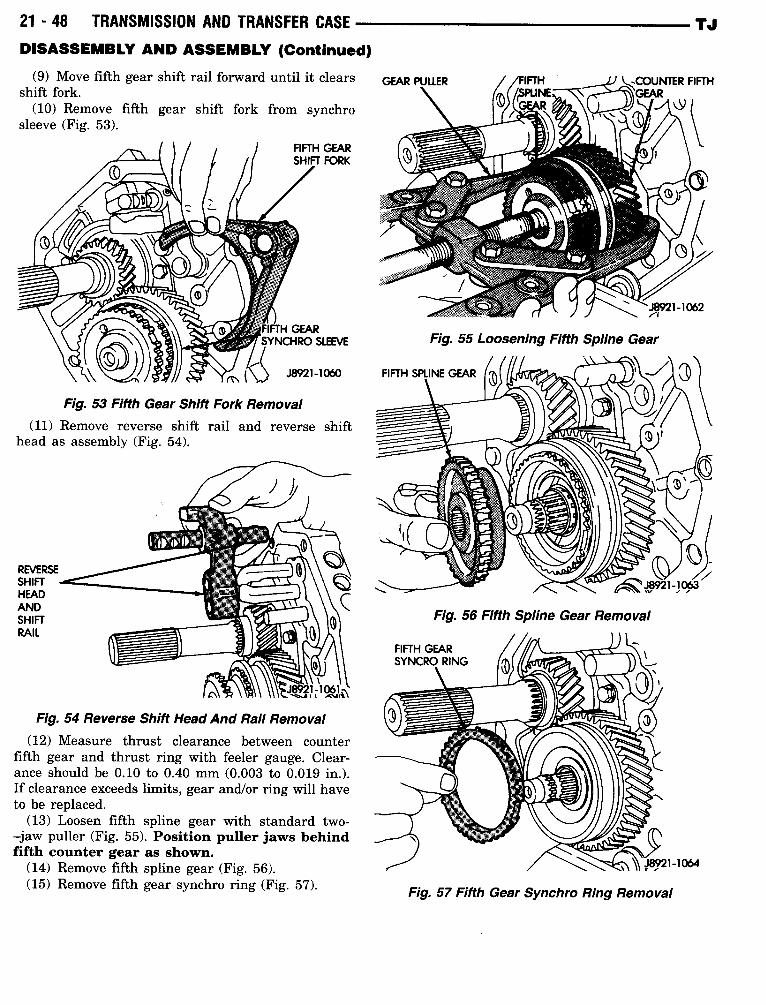
(9) Move fifth gear shift rail forward until it clearsshift fork .
(10) Remove fifth gear shift fork from synchrosleeve (Fig. 53) .
REVERSESHIFTHEADANDSHIFTRAIL
Fig. 53 Fifth Gear Shift Fork Removal(11) Remove reverse shift rail and reverse shift
head as assembly (Fig . 54) .
Fig. 54 Reverse Shift Head And Rail Removal(12) Measure thrust clearance between counter
fifth gear and thrust ring with feeler gauge . Clear-ance should be 0.10 to 0.40 mm (0.003 to 0.019 in.) .If clearance exceeds limits, gear and/or ring will haveto be replaced .
(13) Loosen fifth spline gear with standard two-jaw puller (Fig . 55) . Position puller jaws behindfifth counter gear as shown.
(14) Remove fifth spline gear (Fig. 56) .(15) Remove fifth gear synchro ring (Fig. 57) .
TJ
Fig. 55 Loosening Fifth Spline Gear
FIFTH GEARSYNCRO RING
Fig. 56 Fifth Spline Gear Removal
wFig. 57 Fifth Gear Synchro Ring Removal
TJ
DISASSEMBLY AND ASSEMBLY (Continued)
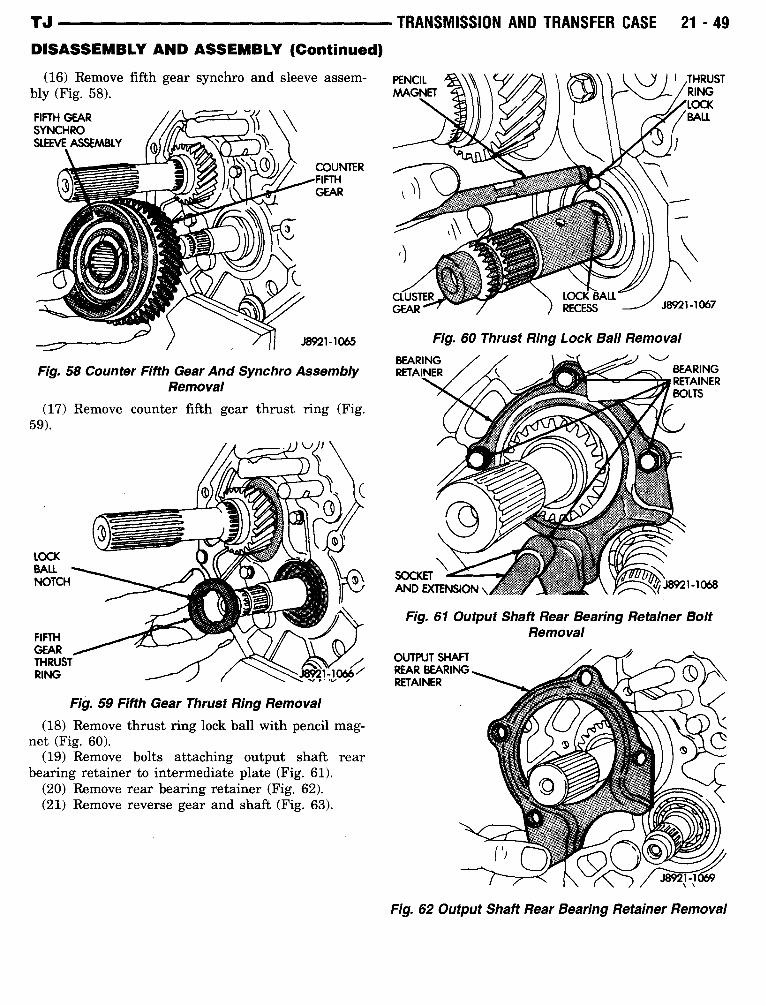
(16) Remove fifth gear synchro and sleeve assem-bly (Fig . 58) .
Fig. 59 Fifth Gear Thrust Ring Removal
Fig. 58 Counter Fifth Gear And Synchro AssemblyRemoval
(17) Remove counter fifth gear thrust ring (Fig.59) .
(18) Remove thrust ring lock ball with pencil mag-net (Fig . 60) .
(19) Remove bolts attaching output shaft rearbearing retainer to intermediate plate (Fig . 61) .
(20) Remove rear bearing retainer (Fig . 62) .(21) Remove reverse gear and shaft (Fig . 63) .
TRANSMISSION AND TRANSFER CASE
21 -49
Fig. 60 Thrust Ring Lock Ball Removal
OUTPUT SHAFTREAR BEARINGRETAINER
Fig. 61 Output Shaft Rear Bearing Retainer BoltRemoval
Fig. 62 Output Shaft Rear Bearing Retainer Removal
21 -50
TRANSMISSION AND TRANSFER CASE -DISASSEMBLY AND ASSEMBLY (Continued)
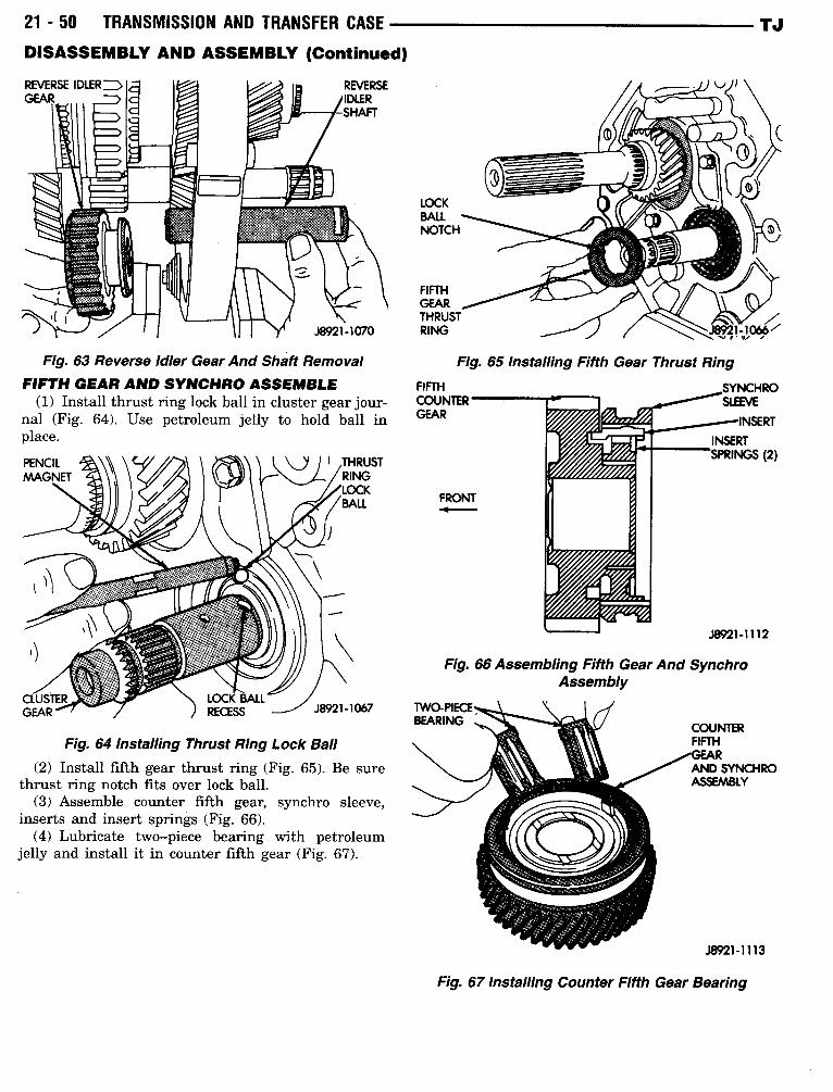
Fig. 63 Reverse Idler Gear And Shaft RemovalFIFTH GEAR AND SYNCHRO ASSEMBLE
(1) Install thrust ring lock ball in cluster gear jour-nal (Fig . 64) . Use petroleum jelly to hold ball inplace .
Fig. 64 Installing Thrust Ring Lock Ball(2) Install fifth gear thrust ring (Fig . 65). Be sure
thrust ring notch fits over lock ball .(3) Assemble counter fifth gear, synchro sleeve,
inserts and insert springs (Fig . 66) .(4) Lubricate two-piece bearing with petroleum
jelly and install it in counter fifth gear (Fig . 67) .
LOCKBALLNOTCH
FRONT
Fig. 65 Installing Fifth Gear Thrust Ring
TJ
FIFTHGEARTHRUSTRING
J8921 lam
-066
FIFTH
SYNCHROCOUNTER
-SLEEVEGEAR
INSERT
INSERTSPRINGS (2)
J8921-1112
Fig. 66 Assembling Fifth Gear And SynchroAssembly
Fig. 67 Installing Counter Fifth Gear Bearing
TJ
DISASSEMBLY AND ASSEMBLY (Continued)
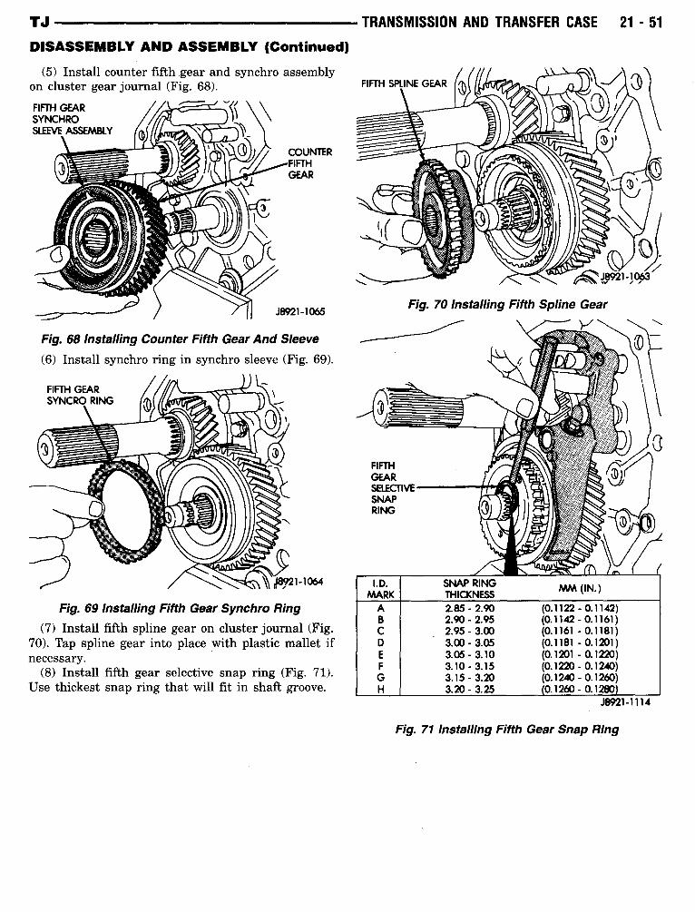
(5) Install counter fifth gear and synchro assemblyon cluster gear journal (Fig . 68) .
Fig. 69 Installing Fifth Gear Synchro Ring
Fig. 68 Installing Counter Fifth Gear And Sleeve
(6) Install synchro ring in synchro sleeve (Fig. 69) .
(7) Install fifth spline gear on cluster journal (Fig .70) . Tap spline gear into place with plastic mallet ifnecessary .
(8) Install fifth gear selective snap ring (Fig . 71) .Use thickest snap ring that will fit in shaft groove .
TRANSMISSION AND TRANSFER CASE
21 -51
J8921-1063
Fig. 70 Installing Fifth Spline Gear
J8921-1114
Fig. 71 Installing Fifth Gear Snap Ring
I .D.MARK
SNAP RINGTHICKNESS MM (IN.)
A 2.85-2.90 (0.1122 - 0.1142)B 2.90-2.95 (0.1142-0.1161)C 2.95-3.00 (0.1161 -0.1181)D 3.00-3.05 (0.1181 - 0.1201)E 3.05-3.10 (0.1201 - 0.1220)F 3.10-3.15 (0.1220 - 0.1240)G 3.15-3.20 (0.1240 - 0.1260)H 3.20-3.25 0.1260 - 0.1280
21 -52
TRANSMISSION AND TRANSFER CASE
TJDISASSEMBLY AND ASSEMBLY (Continued)
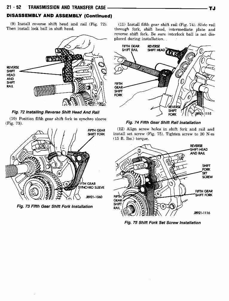
(9) Install reverse shift head and rail (Fig. 72) .
(11) Install fifth gear shift rail (Fig. 74) . SlideThen install lock ball in shift head .
through fork, shift head, intermediate platereverse shift fork . Be sure interlock ball is notplaced during installation.
REVERSESHIFTHEADANDSHIFTRAIL
11
Fig. 72 Installing Reverse ShiftHead And Rail(10) Position fifth gear shift fork in synchro sleeve
(Fig . 73) .
J8921-1060
Fig. 73 Fifth Gear Shift Fork Installation
FIFTH GEARSHIFT FORK
railanddis-
FIFTH GEAR
REVERSESHIFT RAIL
SHIFT HEAD
Fig. 74 Fifth Gear Shift Rail Installation(12) Align screw holes in shift fork and rail and
install set screw (Fig . 75) . Tighten screw to 20 N-m(15 ft . lbs.) torque .
Fig. 75 Shift Fork Set Screw Installation
TJ
DISASSEMBLY AND ASSEMBLY (Continued)
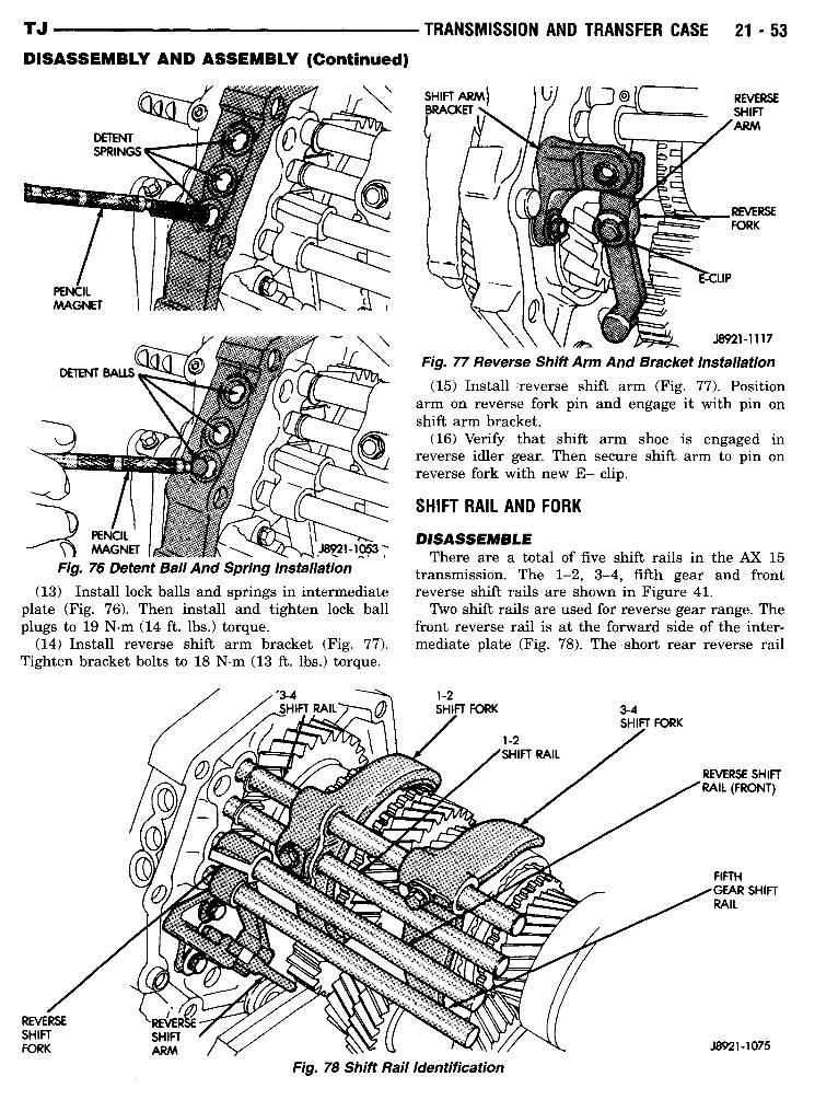
Fig. 76 Detent Ball And Spring Installation(13) Install lock balls and springs in intermediate
plate (Fig . 76) . Then install and tighten lock ballplugs to 19 N-m (14 ft . lbs .) torque .
(14) Install reverse shift arm bracket (Fig. 77) .Tighten bracket bolts to 18 N-m (13 ft . lbs .) torque .
TRANSMISSION AND TRANSFER CASE
21 -53
\\ \I;
J892i-1117
Fig. 77 Reverse Shift Arm And Bracket Installation(15) Install reverse shift arm (Fig . 77) . Position
arm on reverse fork pin and engage it with pin onshift arm bracket .
(16) Verify that shift arm shoe is engaged inreverse idler gear. Then secure shift arm to pin onreverse fork with new E- clip .
SHIFT RAIL AND FORK
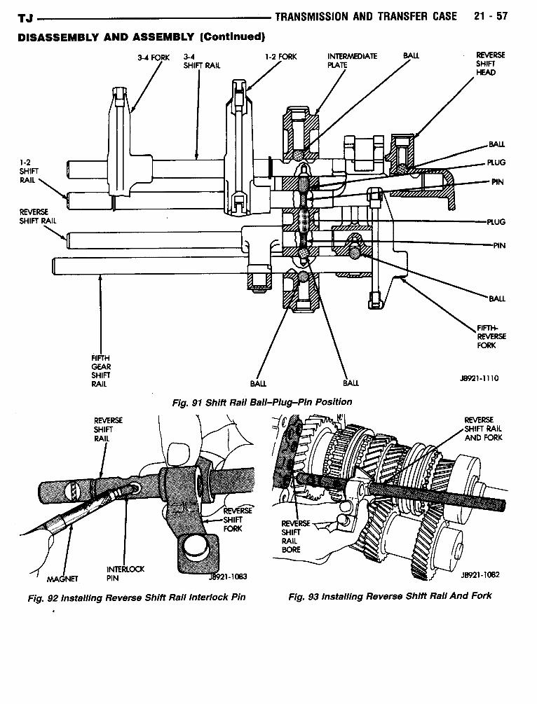
DISASSEMBLEThere are a total of five shift rails in the AX 15
transmission . The 1-2, 3-4, fifth gear and frontreverse shift rails are shown in Figure 41 .Two shift rails are used for reverse gear range . The
front reverse rail is at the forward side of the inter-mediate plate (Fig . 78) . The short rear reverse rail
Fig. 78 Shift Rail Identification
21 -54
TRANSMISSION AND TRANSFER CASEDISASSEMBLY AND ASSEMBLY (Continued)
and reverse shift head are at the rear side of theintermediate plate .
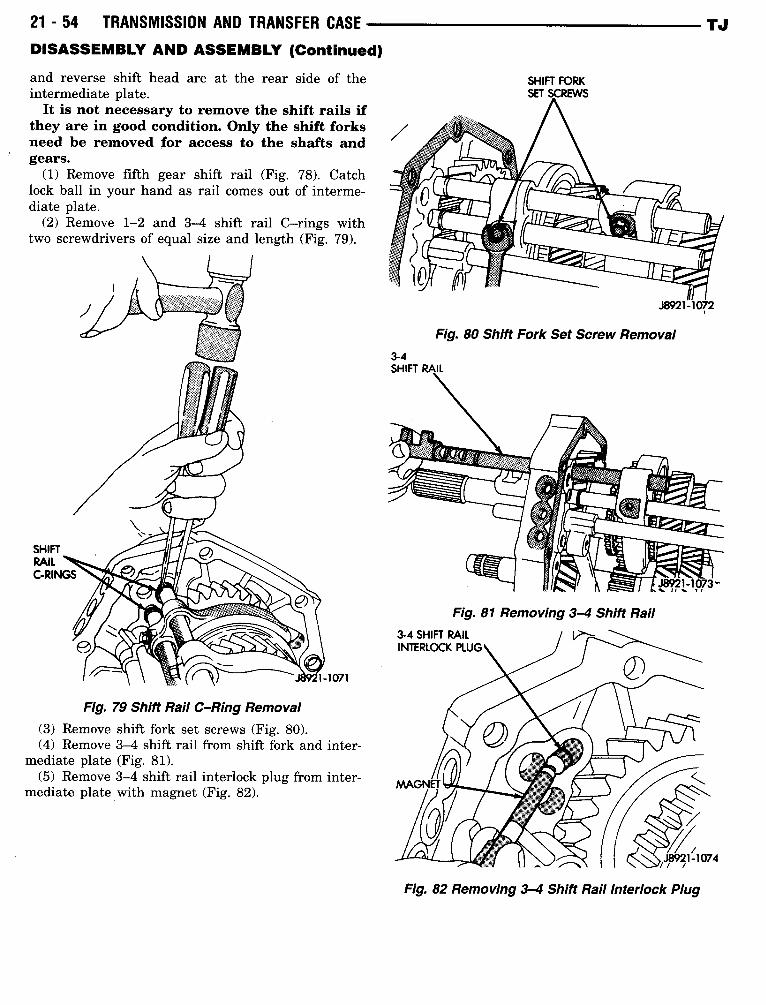
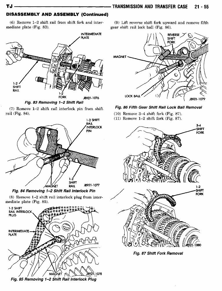
It is not necessary to remove the shift rails ifthey are in good condition . Only the shift forksneed be removed for access to the shafts andgears.
(1) Remove fifth gear shift rail (Fig . 78) . Catchlock ball in your hand as rail comes out of interme-diate plate .
(2) Remove 1-2 and 3-4 shift rail C-rings withtwo screwdrivers of equal size and length (Fig. 79) .
Fig. 79 Shift Rail C-Ring Removal(3) Remove shift fork set screws (Fig . 80) .(4) Remove 3-4 shift rail from shift fork and
mediate plate (Fig . 81) .(5) Remove 3-4 shift rail interlock plug from
mediate plate with magnet (Fig . 82).
inter-
inter-
3-4SHIFT RAIL
SHIFT FORKSET SCREWS
Fig. 80 Shift Fork Set Screw Removal
Fig. 81 Removing 3-4 Shift Rail
J8921-1072
Fig. 82 Removing 3-4 Shift Rail Interlock Plug
TJ
TJ
TRANSMISSION AND TRANSFER CASE
21 -55DISASSEMBLY AND ASSEMBLY (Continued)
(6) Remove 1-2 shift rail from shift fork and inter-
(9) Lift reverse shift fork upward and remove fifthmediate plate (Fig. 83) .
gear shift rail lock ball (Fig . 86) .
1-2FORK ,)8921-1076
Fig. 83 Removing 1-2 Shift Rail
(7) Remove 1-2 shift rail interlock pin from shiftrail (Fig . 84) .
(10) Remove 3-4 shift fork (Fig. 87) .
mediate plate (Fig. 85) .
1-2SHIFT
MAGNET RAIL J8921-1077
Fig. 84 Removing 1-2 Shift Rail Interlock Pin
(8) Remove 1-2 shift rail interlock plug from inter-
MAGNET 13921-1078..1 1
. . .
Fig. 85 Removing 12 Shift Rail Interlock Plug
Fig. 86 Fifth Gear Shift Rail Lock Ball Removal
1-2 SHIFT
(11) Remove 1-2 shift fork (Fig . 87) .
Fig. 87 Shift Fork Removal
21 - 56
TRANSMISSION AND TRANSFER CASE
DISASSEMBLY AND ASSEMBLY (Continued)
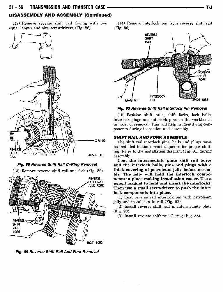
(12) Remove reverse shift rail C-ring with two
(14) Removeequal length and size screwdrivers (Fig . 88) .
(Fig. 90) .
Fig. 88 Reverse Shift Rail C-Ring Removal
(13) Remove reverse shift rail and fork (Fig . 89) .c
Fig. 89 Reverse Shift Rail And Fork Removal
TJ
interlock pin from reverse shift rail
Fig. 90 Reverse Shift Rail Interlock Pin Removal
(15) Position shift rails, shift forks, lock balls,interlock plugs and interlock pins on the workbenchin order of removal . This will help in identifying com-ponents during inspection and assembly.
SHIFT RAIL ANDFORK ASSEMBLEThe shift rail interlock pins, balls and plugs must
be installed in the correct sequence for proper shift-ing. Refer to the installation diagram (Fig . 91) duringassembly .Coat the intermediate plate shift rail bores
and the interlock balls, pins and plugs with athick covering of petroleum jelly before assem-bly. The jelly will hold the interlock compo-nents in place making installation easier. Use apencil magnet to hold and insert the interlocks.Then use a small screwdriver to push the inter-lock components into place.
(1) Coat reverse rail interlock pin with petroleumjelly and install pin in rail (Fig . 92) .
(2) Install reverse shift rail in intermediate plate(Fig. 93) .
(3) Install reverse shift rail C-ring (Fig. 88) .
TJ
DISASSEMBLY AND ASSEMBLY (Continued)
1-2SHIFTRAIL
REVERSESHIFT RAIL
-~ire.
or i`
1~I11111111I
vii
i
FIFTHGEARSHIFTRAIL
REVERSESHIFTRAIL
3-4 FORK
3-4SHIFT RAIL
Fig. 91 Shift Rail Ball-Plug-Pin Positionc
TRANSMISSION AND TRANSFER CASE
21 -57
1-2 FORK INTERMEDIATE BALL REVERSESHIFTHEAD
PLATE
BALL
MAGNET
Fig. 92 Installing Reverse Shift Rail Interlock Pin
Fig, 93 Installing Reverse Shift Rail And Fork
BALL
PLUG
PIN
PLUG
FIFTH-REVERSEFORK
Jm1-1110
PIN
21 -58
TRANSMISSION AND TRANSFER CASEDISASSEMBLY AND ASSEMBLY (Continued)
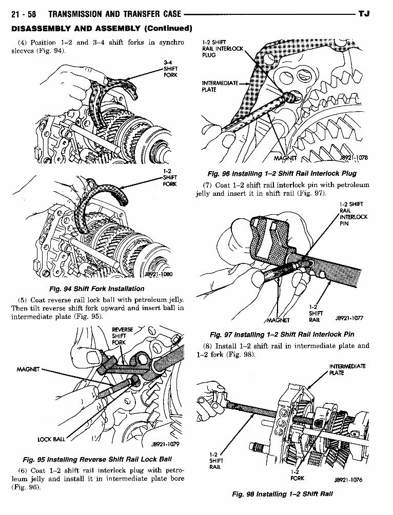
(4) Position 1-2 and 3-4 shift forks in synchrosleeves (Fig. 94) .
Fig. 94 Shift Fork Installation(5) Coat reverse rail lock ball with petroleum jelly.
Then tilt reverse shift fork upward and insert ball inintermediate plate (Fig. 95) .
Fig. 95 Installing Reverse Shift Rail Lock Ball
(6) Coat 1-2 shift rail interlock plug with petro-leum jelly and install it in intermediate plate bore(Fig . 96) .
TJ
Fig. 96 Installing 1-2 Shift Rail Interlock Plug
(7) Coat 1-2 shift rail interlock pin with petroleumjelly and insert it in shift rail (Fig . 97) .
1-2FORK
Fig. 98 Installing 12 Shift Rail
Fig. 97 Installing 12 Shift Rail Interlock Pin
(8) Install 1-2 shift rail in intermediate plate and1-2 fork (Fig . 98) .
J8921-1076
TJ
DISASSEMBLY AND ASSEMBLY (Continued)
(9) Coat 3-4 shift rail interlock plug with petro-leum jelly and install plug in intermediate plate (Fig .99) .
Fig. 100 Installing 3-4 Shift Rail
OUTPUT SHAFT AND CLUSTER GEAR
Fig. 99 Installing 3-4 Shift Rail Interlock Plug
(10) Install 3-4 shift rail in intermediate plate andin both shift forks (Fig . 100) .
(11) Verify that none of the interlock balls, plugs,or pins were displaced during shift rail installation .
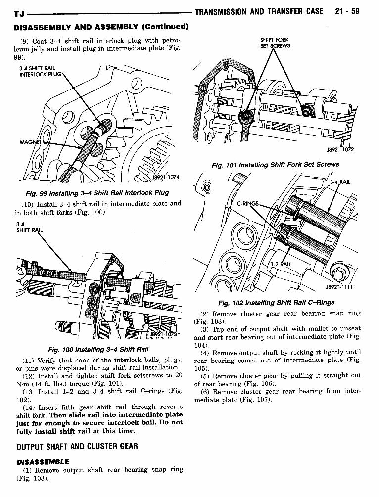
(12) Install and tighten shift fork setscrews to 20N-m (14 ft . lbs .) torque (Fig. 101) .
(13) Install 1-2 and 3-4 shift rail C-rings (Fig .102) .
(14) Insert fifth gear shift rail through reverseshift fork. Then slide rail into intermediate platejust far enough to secure interlock ball. Do notfully install shift rail at this time.
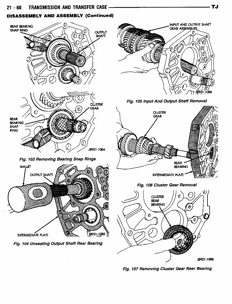
DISASSEMBLE(1) Remove output shaft rear bearing snap ring
(Fig. 103) .
TRANSMISSION AND TRANSFER CASE
21 -59
Fig . 101 Installing Shift Fork Set Screws
Fig. 102 Installing Shift Rail C-Rings
J8921-1072
J8921-1111 -
(2) Remove cluster gear rear bearing snap ring(Fig . 103) .
(3) Tap end of output shaft with mallet to unseatand start rear bearing out of intermediate plate (Fig .104) .
(4) Remove output shaft by rocking it lightly untilrear bearing comes out of intermediate plate (Fig.105) .
(5) Remove cluster gear by pulling it straight outof rear bearing (Fig . 106) .
(6) Remove cluster gear rear bearing from inter-mediate plate (Fig . 107) .
21 - 60
TRANSMISSION AND TRANSFER CASE
TJ
DISASSEMBLY AND ASSEMBLY (Continued)
Fig. 103 Removing Bearing Snap Rings
MALLET
OUTPUT SHAFT
8921,-1085-M_"
Fig. 104 Unseating Output Shaft Rear Bearing
INTERMEDIATE PLATE
F
Fig. 105 Input And Output Shaft Removal
Fig. 106 Cluster Gear Removal
.18921-1088
Fig . 107 Removing Cluster Gear Rear Bearing
TJ
DISASSEMBLY AND ASSEMBLY (Continued)
Fig. 108 Input Shaft Removal
J8921-1089
OUTPUT SHAFT
/
INPUT SHAFT
PILOT BEARING
,ASSEMBLY
VISEJAWS
J8921-1090Fig. 109 Input Shaft Pilot Bearing Removal
TRANSMISSION AND TRANSFER CASE
21 -61
Fig. 111 Mounting Intermediate Plate And Geartrain In Vise
Fig. 110 Input Shaft Components
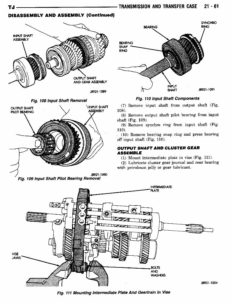
(7) Remove input shaft from output shaft (Fig .108) .
(8) Remove output shaft pilot bearing from inputshaft (Fig. 109) .
(9) Remove synchro ring from input shaft (Fig .110) .
(10) Remove bearing snap ring and press bearingoff input shaft (Fig . 110) .
OUTPUT SHAFT AND CLUSTER GEARASSEMBLE
(1) Mount intermediate plate in vise (Fig . 111) .(2) Lubricate cluster gear journal and rear bearing
with petroleum jelly or gear lubricant .
21 -62
TRANSMISSION AND TRANSFER CASE -
DISASSEMBLY AND ASSEMBLY (Continued)
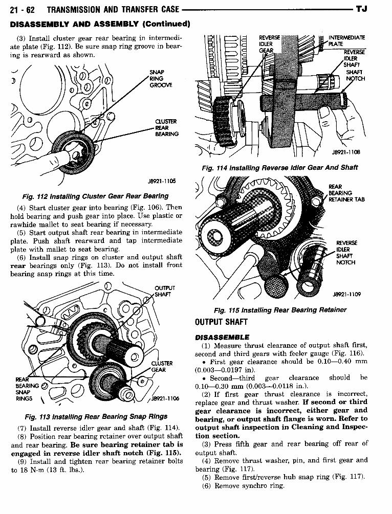
(3) Install cluster gear rear bearing in intermedi-ate plate (Fig. 112) . Be sure snap ring groove in bear-ing is rearward as shown.
Fig. 112 Installing Cluster Gear Rear Bearing
(4) Start cluster gear into bearing (Fig . 106) . Thenhold bearing and push gear into place . Use plastic orrawhide mallet to seat bearing if necessary.
(5) Start output shaft rear bearing in intermediateplate . Push shaft rearward and tap intermediateplate with mallet to seat bearing .
(6) Install snap rings on cluster and output shaftrear bearings only (Fig. 113) . Do not install frontbearing snap rings at this time .
Fig. 113 Installing Rear Bearing Snap Rings
(7) Install reverse idler gear and shaft (Fig. 114) .(8) Position rear bearing retainer over output shaft
and rear bearing . Be sure bearing retainer tab isengaged in reverse idler shaft notch (Fig. 115).
(9) Install and tighten rear bearing retainer boltsto 18 N-m (13 ft . lbs .) .
OUTPUT SHAFT
Fig. 114 Installing Reverse Idler Gear And Shaft
Fig. 115 Installing Rear Bearing Retainer
TJ
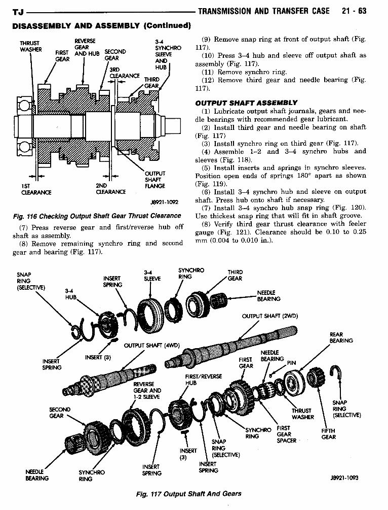
DISASSEMBLE(1) Measure thrust clearance of output shaft first,
second and third gears with feeler gauge (Fig. 116) ." First gear clearance should be 0.10-0.40 mm
(0 .003-0.0197 in) ." Second-third gear clearance should be
0.10-0.30 mm (0.003-0.0118 in.).(2) If first gear thrust clearance is incorrect,
replace gear and thrust washer. If second or thirdgear clearance is incorrect, either gear andbearing, or output shaft flange is worn. Refer tooutput shaft inspection in Cleaning and Inspec-tion section.
(3) Press fifth gear and rear bearing off rear ofoutput shaft .
(4) Remove thrust washer, pin, and first gear andbearing (Fig . 117) .
(5) Remove first/reverse hub snap ring (Fig. 117) .(6) Remove synchro ring .
TJ
DISASSEMBLY AND ASSEMBLY (Continued)
THRUSTWASHER
SNAPRING(SELECTIVE)
I/I~11/I"IIII~
1STCLEARANCE
J8921-1092
Fig. 116 Checking Output Shaft Gear Thrust Clearance
(7) Press reverse gear and first/reverse hub offshaft as assembly.
(8) Remove remaining synchro ring and secondgear and bearing (Fig. 117) .
INSERTSPRING
TRANSMISSION AND TRANSFER CASE
21 -63
OUTPUT SHAFTASSEMBLY(1) Lubricate output shaft journals, gears and nee-
dle bearings with recommended gear lubricant .(2) Install third gear and needle bearing on shaft
(Fig. 117)(3) Install synchro ring on third gear (Fig. 117) .(4) Assemble 1-2 and 3-4 synchro hubs and
shaft . Press hub onto shaft if necessary.(7) Install 3-4 synchro hub snap ring (Fig . 120) .
Use thickest snap ring that will fit in shaft groove.(8) Verify third gear thrust clearance with feeler
gauge (Fig . 121) . Clearance should be 0.10 to 0.25mm (0.004 to 0.010 in.) .
SYNCHRO FIRST
RING GEARSNAP SPACER
INSERT RING
(3)
I (SELECTIVE)
INSERTSPRING
Fig. 117 Output Shaft And Gears
REARBEARING
J8921-1093
REVERSE 3-4 (9) Remove snap ring at front of output shaft (Fig.
FIRSTGEARAND HUB SECOND
SYNCHROSLEEVE
117) .(10) Press 3-4 hub and sleeve off output shaft as
GEAR GEAR AND assembly (Fig . 117) .3RD HUB
(11) Remove synchro ring .CLEARANCE
THIRD (12) Remove third gear and needle bearing (Fig .GEAR 117) .
sleeves (Fig . 118) .(5) Install inserts and springs in synchro sleeves .
OUTPUT Position open ends of springs 180° apart as shown2ND
SHAFTFLANGE (Fig. 119) .
CLEARANCE (6) Install 3-4 synchro hub and sleeve on output
21 -64
TRANSMISSION AND TRANSFER CASE --DISASSEMBLY AND ASSEMBLY (Continued)
3-4 SLEEVEAND HUB ti
SLEEVE
FRONT
"\N-
F7,711F7,7111!1111
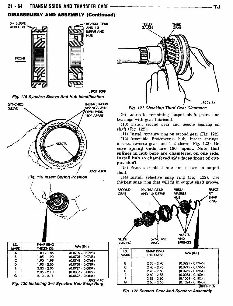
J8921-1099Fig. 118 Synchro Sleeve And Hub Identification
SYNCHRO
INSTALL INSERTSPRINGS WITHOPEN ENDS180° APART
Fig. 119 Insert Spring Position
REVERSE GEARAND 1-2SLEEVE ANDHUB
J8921-1100
J8921-1101Fig- 120 Installing 3-4 Synchro Hub Snap Ring
FEELER THIRDGAUGE GEAR
J8921-56Fig. 121 Checking Third Gear Clearance
TJ
(9) Lubricate remaining output shaft gears andbearings with gear lubricant .
(10) Install second gear and needle bearing onshaft (Fig . 122) .
(11) Install synchro ring on second gear (Fig . 122) .(12) Assemble first/reverse hub, insert springs,
inserts, reverse gear and 1-2 sleeve (Fig. 122) . Besure spring ends are 180° apart. Note thatsplines in hub bore are chamfered on one side .Install hub so chamfered side faces front of out-put shaft.
(13) Press assembled hub and sleeve on outputshaft.
(14) Install selective snap ring (Fig. 122) . Usethickest snap ring that will fit in output shaft groove .
SECOND
REVERSE GEAR
FIRST/
SELECTGEAR
AND 1-2 SLEEVE
REVERSE
FITHUB /SNAP
RING
INSERTSNEEDLE SYNCHRO ANDBEARING RING SPRINGS
.18921-1102Fig. 122 Second Gear And Synchro Assembly
I .D.MARK
SNAP RINGTHICKNESS MM (IN.)
A 1 .80-1 .85 (0.0709 - 0.0728)B 1 .85-1 .90 (0.0728 - 0.0748)C 1 .90-1 .95 (0.0748 - 0.0768)D 1 .95-2.00 (0.0768 - 0.0787)E 2.00-2.05 (0.0787 - 0.0807)F 2.05-2.10 (0.0807 - 0.0827)G 2.10-2.15 0.0827 - 0.0846
I .D .MARK
SNAP RINGTHICKNESS MM (IN .)
B 2.35-2.40 (0.0925 - 0.0945)C 2.40-2.45 (0.0945 - 0.0965)D 2.45-2.50 (0.0965 - 0.0984)E 2.50-2.55 (0.0984 - 0 .1 OD4)F 2.55-2.60 (0.1004 - 0.1024)G 2.60-2.65 0.1024 - 0.1043
TJ
DISASSEMBLY AND ASSEMBLY (Continued)
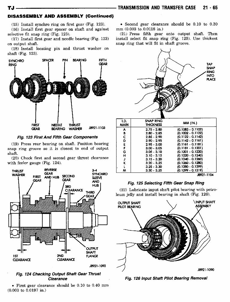
(15) Install synchro ring on first gear (Fig . 123) .(16) Install first gear spacer on shaft and against
selective fit snap ring (Fig . 123) .(17) Install first gear and needle bearing (Fig. 123)
on output shaft .(18) Install locating pin and thrust washer on
shaft (Fig . 123) .
FIRST NEEDLE THRUSTGEAR
BEARING WASHER J8921-1103
Fig. 123 FirstAnd Fifth Gear Components(19) Press rear bearing on shaft. Position bearing
snap ring groove so it is closest to end of outputshaft .
(20) Check first and second gear thrust clearancewith feeler gauge (Fig . 124) .
THRUSTWASHER
:10m,""-IPIN@!IM1101
I 1j:E
GEAR
OUTPUTSHAFT
1ST
2ND
FLANGECLEARANCE CLEARANCE
J8921-1092
Fig. 124 Checking Output Shaft Gear ThrustClearance
" First gear clearance should be 0.10 to 0.40 mm(0.003 to 0.0197 in.)
TRANSMISSION AND TRANSFER CASE
21 - 65
" Second gear clearance should be 0.10 to 0.30mm (0.003 to 0.0118 in.)
(21) Press fifth gear onto output shaft . Theninstall select fit snap ring (Fig . 125) . Use thickestsnap ring that will fit in shaft groove.
Fig. 125 Selecting Fifth Gear Snap Ring
Fig. 126 Input Shaft Pilot Bearing Removal
TAPSNAPRINGINTOPLACE
J8921-1104
(22) Lubricate input shaft pilot bearing with petro-leum jelly and install bearing in shaft (Fig . 126) .
OUTPUT SHAFT
/
INPUT SHAFTPILOT BEARING
ASSEMBLY
J8921-1090
I .D.MARK
SNAP RINGTHICKNESS MM (IN.)
A 2.75-2.80 (0.1083 - 0.1102)B 2.80-2.85 (0.1002 - 0.1122)C 2.85-2.90 (0.1122 - 0.1142)D 2.90-2.95 (0.1142-0.1161)E 2.95-3.00 (0.1161 -0.1181)F 3.00-3.05 (0.1181 - 0.1201)G 3.05-3.10 (0.1201 - 0.1220)H 3.10-3.15 (0.1220 - 0.1240)J 3.15-3.20 (0.1240 - 0.1260)K 3.20-3.25 (0.1260 - 0.1280)
_ L 3.25-3.30 (0.1280 - 0.1299)M 3.30-3.35 0.1299 - 0.1319REVERSE 3-4
GEAR SYNCHROFIRST AND HUB SECOND SLEEVEGEAR I GEAR AND
3RD HUBCLEARANCE THIRD

21 - 66
TRANSMISSION AND TRANSFER CASE -
DISASSEMBLY AND ASSEMBLY (Continued)
(23) Install input shaft on output shaft (Fig. 127) .Be sure output shaft hub is fully seated in pilot bear-ing .
CLEANING AND INSPECTION
AX15 TRANSMISSIONClean the transmission components in solvent .
Then dry the cases, gears, shift mechanism andshafts with compressed air. Dry the bearings withclean, dry shop towels only. Never use com-pressed air on the bearings . This could damagethe bearing rollers .Replace components that are obviously worn,
cracked, chipped or damaged.
THRUSTWASHER
Fig. 127 Input Shaft Removal
REVERSEGEAR
FIRST AND HUB SECONDGEAR I GEAR
J8921-1089
OUTPUTSHAFTFLANGE1ST
2NDCLEARANCE CLEARANCE
JM1-1092
Fig. 128 Checking Output Shaft Gear Thrust Clearance
Inspect the transmission case . Replace the case ifcracked or porous or if any of the bearing and gearbores are damaged.
OUTPUT SHAFT INSPECTIONMeasure thickness of the output shaft flange with
a micrometer (Fig. 129) . Minimum allowable flangethickness is 4.70 mm (0.185 in) .
If shaft flange thickness is OK but previouslymeasured second/third gear thrust clearancewas incorrect (Fig. 128), replace the necessarygear and needle bearing as an assembly.Check diameter of the first, second and third gear
bearing surfaces of the output shaft (Fig . 129) . Mini-mum allowable diameters are :
" 38.86 mm (1.529 in.) for first gear surface" 46.86 mm (1 .844 in.) for second gear surface" 37.86 mm (1 .490 in.) for third gear surface
FIRSTGEARSURFACE
V-BLOCKS
POSITION
TJ
SHAFTFLANGE
THIRDGEARSURFACE
DIALINDICATOR HERETO CHECK RUNOUT
J8921-1094
Fig. 129 Checking Output Shaft Tolerances
TJ
CLEANING AND INSPECTION (Continued)
Check output shaft runout with V-blocks and adial indicator (Fig. 129) . Maximum allowable runoutis 0.06 mm (0.0024 in.) .Replace the output shaft if any surface measured
fails to meet stated tolerance .
CLUSTER GEAR INSPECTIONInspect the cluster gear teeth . Replace the gear if
any teeth are worn or damaged or if the bearing sur-faces are damaged .Check diameter of the cluster gear journal with a
micrometer (Fig. 130) . Minimum allowable diameteris 27.860 mm (1 .096 in.) .
Fig. 130 Checking Cluster Gear Journal Diameter
Check condition of the cluster gear front bearing .Replace the bearing if worn, noisy, or damaged.
AX15 COMPONENTS
GEARTRAIN ANDSYNCNROInstall the synchro rings on their respective gears .
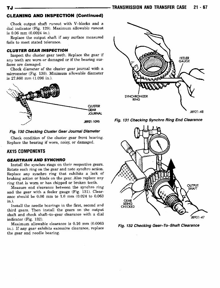
Rotate each ring on the gear and note synchro action .Replace any synchro ring that exhibits a lack ofbraking action or binds on the gear. Also replace anyring that is worn or has chipped or broken teeth.Measure end clearance between the synchro ring
and the gear with a feeler gauge (Fig . 131) . Clear-ance should be 0.06 mm to 1.6 mm (0.024 to 0.063in.) .
Install the needle bearings in the first, second andthird gears . Then install the gears on the outputshaft and check shaft-to-gear clearance with a dialindicator (Fig. 132) .Maximum allowable clearance is 0.16 mm (0.0063
in.) . If any gear exhibits excessive clearance, replacethe gear and needle bearing.
TRANSMISSION AND TRANSFER CASE
21 - 67
SYNCHRONIZERRING
FEELERGAUGE
J8921-48
Fig. 131 Checking Synchro Ring End Clearance
Fig. 132 Checking Gear-To-Shaft Clearance
21 -68
TRANSMISSION AND TRANSFER CASE
CLEANING AND INSPECTION (Continued)
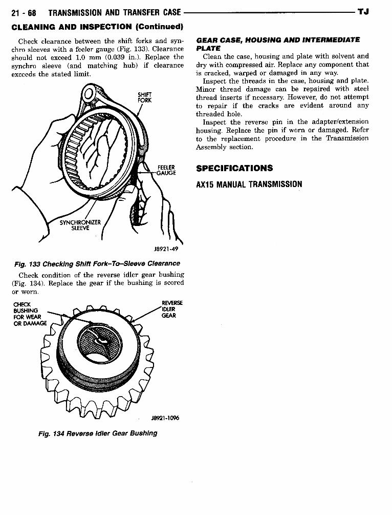
Check clearance between the shift forks and syn-chro sleeves with a feeler gauge (Fig . 133) . Clearanceshould not exceed 1.0 mm (0.039 in.). Replace thesynchro sleeve (and matching hub) if clearanceexceeds the stated limit.
Fig. 134 Reverse Idler Gear Bushing
Fig. 133 Checking Shift Fork-To-Sleeve ClearanceCheck condition of the reverse idler gear bushing
(Fig. 134) . Replace the gear if the bushing is scoredor worn.
TJ
GEAR CASE, HOUSING AND INTERMEDIATEPLATEClean the case, housing and plate with solvent and
dry with compressed air. Replace any component thatis cracked, warped or damaged in any way.
Inspect the threads in the case, housing and plate .Minor thread damage can be repaired with steelthread inserts if necessary. However, do not attemptto repair if the cracks are evident around anythreaded hole .
Inspect the reverse pin in the adapter/extensionhousing . Replace the pin if worn or damaged. Referto the replacement procedure in the T~-ansmissionAssembly section .
SPECIFICATIONS
AX15 MANUAL TRANSMISSION
TJ
TRANSMISSION AND TRANSFER CASE
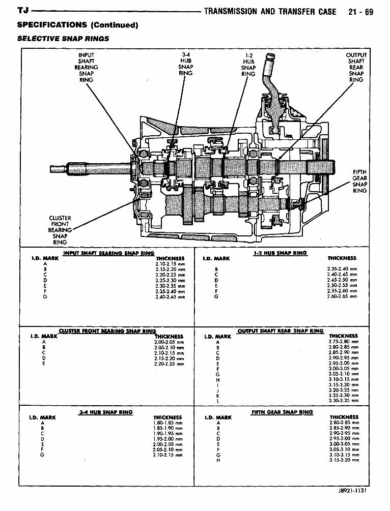
21 - 69SPECIFICATIONS (Continued)SELECTIVE SNAP RINGS
J8921-1131
INPUT 3-4 1-2 OUTPUTSHAFT HUB HUB SHAFT
BEARING SNAP SNAP REARSNAP RING RING SNAPRING - RING
FIFTH~ 7I T':I !~
~t I~~
GEARSNAP.
E RING
CLUSTERFRONT
I1..BEARINGSNAPRING
INPUT SHAFT BEARING SNAP RING 1.2 NUB SNAP RINGI.D . MARK THICKNESS I.D . MARK THICKNESS
A 2.10-2.15 mmB 2,15-2 .20 mm B 2.35-2.40 mmC 2.20-2.25 mm C 2.40-2.45 mmD 2.25-2.30 mm D 2.45-2.50 mmE 2.30-2.35 mm E 2.50-2.55 mmF 2.35-2.40 mm F 2.55-2.60 mmG 2.40-2.45 mm G 2.60-2.65 mm
CLUSTER FRONT BEARING SNAP RING OUTPUT SHAFT REAR SNAP RINGI.D . MARK THICKNESS I.D. MARK THICKNESS
A 2.00-2.05 mm A 2.75-2.80 mmB 2.05-2.10 mm B 2.80-2.85 mmC 2.10-2.15 mm C 2.85-2.90 mmD 2.15-2.20 mm D 2.90-2.95 mmE 2.20-2.25 mm E 2.95-3.00 mm
F 3.00-3.05 mmG 3.05-3.10 mmH 3.10-3.15 mm
3.15-3.20 mm3.20-3.25 mm
K 3.25-3.30 mm3.30-3.35 mm
3-4 HUBSNAP RING FIFTH GEAR SNAP RINGI.D . MARK THICKNESS I.D. MARK THICKNESS
A 1 .80-1.85 mm A 2.80-2.85 mmB 1 .85-1.90 mm B 2.85-2.90 mmC 1 .90-1.95 mm C 2.90-2.95 mmD 1 .95-2.00 mm D 2.95-3.00 mmE 2.00-2.05 mm E 3.00-3.05 mmF 2.05-2.10 mm F 3.05-3.10 mmG 2.10-2.15 mm G 3.10-3.15 mm
` H 3.15-3.20 mm
21 -70
TRANSMISSION AND TRANSFER CASE
TJ
SPECIFICATIONS (Continued)
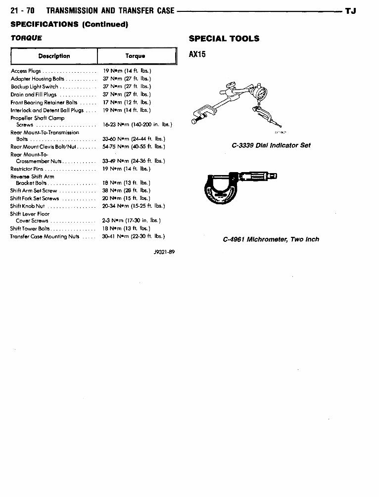
TORQUE
SPECIAL TOOLS
Description
Torque
J9321-89
AX15
Access Plugs . . . . . . . . . . . . . . . . . . .
19 Nom (14 ft. lbs . )Adapter Housing Bolts . . . . . . . . . . .
37 Nom (27 ft. lbs .)Backup Light Switch . . . . . . . . . . . . .
37 Nom (27 ft. lbs .)Drain and Fill Plugs . . . . . . . . . . . . .
37 Nom (27 ft . lbs.)Front Bearing Retainer Bolts . . . . . .
17 Nom (12 ft . lbs. )Interlock and Detent Ball Plugs . . . .
19 Nem (14 ft. lbs. )Propeller Shaft Clamp
Screws . . . . . . . . . . . . . . . . . . . . .
16-23 Nom (140-200 in . lbs .)Rear Mount-To-Transmission
Bolts . . . . . . . . . . . . . . . . . . . . . . .
33-60 Nom (24-44 ft. lbs. )Rear Mount Clevis Bolt/Nut . . . . . . .
5475 Nom (40-55 ft. lbs.)
C-3339 Dial Indicator SetRear Mount-To-Crossmember Nuts . . . . . . . . . . . .
33-49 Nom (2436 ft. lbs.)Restrictor Pins . . . . . . . . . . . . . . . . . .
19 Nom (114 ft. lbs .)Reverse Shift Arm
Bracket Bolts . . . . . . . . . . . . . . . . .
18 Nem (13 ft .
lbs. )Shift Arm Set Screw . . . . . . . . . . . . .
38 Nom (28 ft. lbs .)Shift Fork Set Screws . . . . . . . . . . . .
20 Nom (15 ft . lbs .)Shift Knob Nut . . . . . . . . . . . . . . . . .
20-34 Nom (1525 ft. lbs. )Shift Lever Floor
Cover Screws . . . . . . . . . . . . . . . .
2-3 Nam (17-30 in. lbs.)Shift Tower Bolts . . . . . . . . . . . . . . . .
18 Nom (13 ft. lbs.)Transfer Case Mounting Nuts . . . . .
30-41 K10- (22-30 ft . lbs . ) C-4961 Michrometer, Two Inch