Embed Size (px)
Citation preview
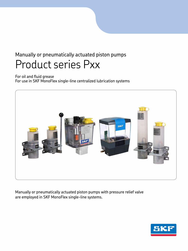
Manually or pneumatically actuated piston pumps with pressure relief valve are employed in SKF MonoFlex single-line systems.
Manually or pneumatically actuated piston pumps
Product series PxxFor oil and fluid grease For use in SKF MonoFlex single-line centralized lubrication systems
PU
B L
S/P
2 1
12
18
EN
· 1
-11
10
-EN
CAD models for products shown in
this brochure can be downloaded at:
skf-lubrication.partcommunity.com
!Important information on product usageSKF and Lincoln lubrication systems or their components are not
approved for use with gases, liquefied gases, pressurized gases in solution and fluids with a vapor pressure exceeding normal atmospheric pressure (1 013 mbar) by more than 0,5 bar at their maximum permissible temperature.
2
PU
B L
S/P
2 1
12
18
EN
· 1
-11
10
-EN
General Information
SKF MonoFlex piston pumps have a limited
displacement per stroke, which limits the
metered quantity and expansion of a system.
These pumps are equipped with a relief
device necessary for operation of the piston
distributors.
When the pump piston returns to the
normal position, the main line is also
relieved via the pressure relief valve.
The connected load of the system must
be considered when planning the system.
To ensure the reserves required for
pressure build-up, the displacement of the
piston pump should be at least 1.5 times the
connected load.
When planning fluid grease systems, the
compressibility of the grease (approx. 1%)
must also be taken into consideration when
determining the connected load.
The connected load consists of:
a) The sum of all volumes metered by
system distributors
b) + 25% of this value (safety margin)
c) + 1 cm3/m of main line (expansion loss)
d) Compressibility loss with fluid greases
† Table 2
SKF specialists can provide you with
additional information.
CommissioningTo commission the product, fill the reservoir
with lubricant and actuate the pump at
intervals of 5 – 10 seconds until lubricant
discharges at all lubrication points.
The venting process is facilitated by:
• Opening the ends of the main lines until
bubble-free oil or fluid grease discharges
from the ends.
• Filling long lubrication point lines,
especially for distributor ports with low
metering volumes, before connecting to
the lubrication points.
Maintenance1 Check the fill level and fill the reservoir in
time. Use the lubricant in accordance with
the information provided by the manufac-
turer. Always use a screen filter when re-
filling oil.
2 After using the machine for an extended
period of time, inspect all pipe connec-
tions for leakage and actuate the piston
pump to check whether lubricant
discharges at all lubrication points.
Only use original SKF spare parts.
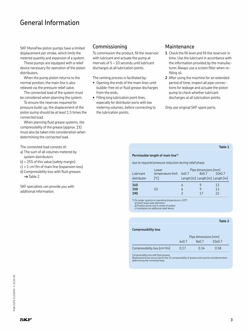
Table 1
Permissible length of main line*)
due to required pressure reduction during relief phase
Lower Pipe dimensions (mm)Lubricant temperature limit 6x0.7 8x0.7 10x0.7
distributor [°C] Length [m] Length [m] Length [m]
34010
6 9 13
350 6 9 13
390 2 17 22
*) On longer systems or operating temperatures <10°C a) Select larger pipe diameters b) Position pump unit in center of system c) Installation an additional relief device
Table 2
Compressibility loss
Pipe dimensions (mm)
6x0.7 8x0.7 10x0.7
Compressibility loss [cm³/m] 0.17 0.34 0.58
Compressibility loss with fluid greases Displacement loss occurs due to the 1% compressibility of grease and must be considered when determining the connected load.
3
PU
B L
S/P
2 1
12
18
EN
· 1
-11
10
-EN
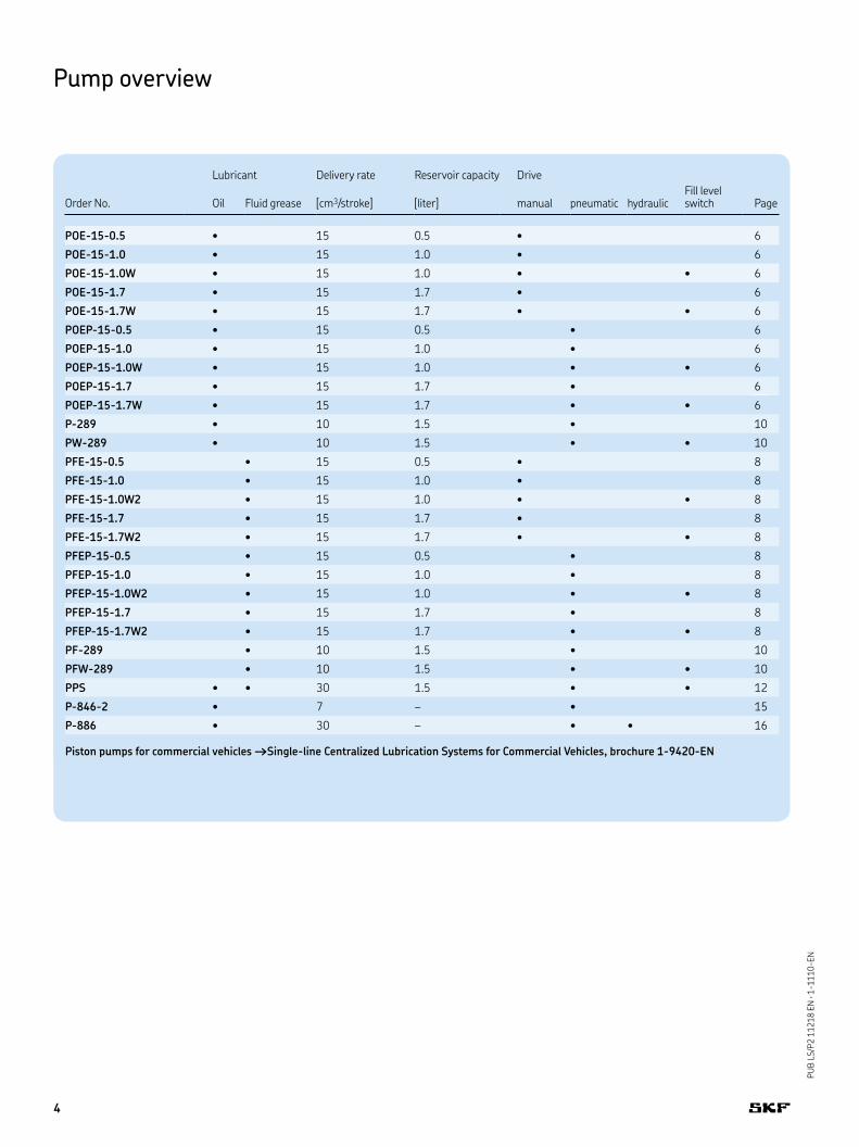
Lubricant Delivery rate Reservoir capacity Drive
Order No. Oil Fluid grease [cm3/stroke] [liter] manual pneumatic hydraulicFill level switch Page
POE-15-0.5 • 15 0.5 • 6
POE-15-1.0 • 15 1.0 • 6
POE-15-1.0W • 15 1.0 • • 6
POE-15-1.7 • 15 1.7 • 6
POE-15-1.7W • 15 1.7 • • 6
POEP-15-0.5 • 15 0.5 • 6
POEP-15-1.0 • 15 1.0 • 6
POEP-15-1.0W • 15 1.0 • • 6
POEP-15-1.7 • 15 1.7 • 6
POEP-15-1.7W • 15 1.7 • • 6
P-289 • 10 1.5 • 10
PW-289 • 10 1.5 • • 10
PFE-15-0.5 • 15 0.5 • 8
PFE-15-1.0 • 15 1.0 • 8
PFE-15-1.0W2 • 15 1.0 • • 8
PFE-15-1.7 • 15 1.7 • 8
PFE-15-1.7W2 • 15 1.7 • • 8
PFEP-15-0.5 • 15 0.5 • 8
PFEP-15-1.0 • 15 1.0 • 8
PFEP-15-1.0W2 • 15 1.0 • • 8
PFEP-15-1.7 • 15 1.7 • 8
PFEP-15-1.7W2 • 15 1.7 • • 8
PF-289 • 10 1.5 • 10
PFW-289 • 10 1.5 • • 10
PPS • • 30 1.5 • • 12
P-846-2 • 7 – • 15
P-886 • 30 – • • 16
Piston pumps for commercial vehicles †Single-line Centralized Lubrication Systems for Commercial Vehicles, brochure 1-9420-EN
Pump overview
4
PU
B L
S/P
2 1
12
18
EN
· 1
-11
10
-EN
Pump overview
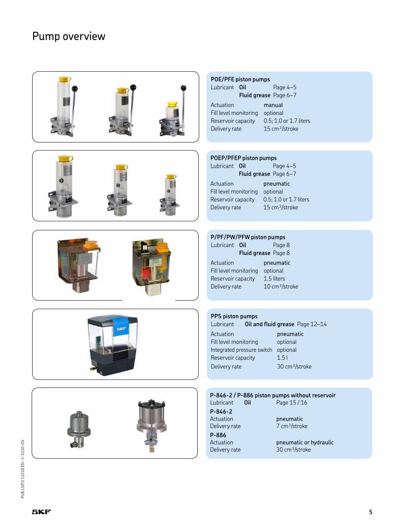
PPS piston pumps
Lubricant Oil and fluid grease Page 12–14
Actuation pneumatic
Fill level monitoring optional
Integrated pressure switch optional
Reservoir capacity 1.5 l
Delivery rate 30 cm³/stroke
POE/PFE piston pumps
Lubricant Oil Page 4–5
Fluid grease Page 6–7
Actuation manual
Fill level monitoring optional
Reservoir capacity 0.5; 1.0 or 1.7 liters
Delivery rate 15 cm³/stroke
POEP/PFEP piston pumps
Lubricant Oil Page 4–5
Fluid grease Page 6–7
Actuation pneumatic
Fill level monitoring optional
Reservoir capacity 0.5; 1.0 or 1.7 liters
Delivery rate 15 cm³/stroke
P/PF/PW/PFW piston pumps
Lubricant Oil Page 8
Fluid grease Page 8
Actuation pneumatic
Fill level monitoring optional
Reservoir capacity 1.5 liters
Delivery rate 10 cm³/stroke
P-846-2 / P-886 piston pumps without reservoirLubricant Oil Page 15 / 16
P-846-2 Actuation pneumatic Delivery rate 7 cm³/stroke
P-886 Actuation pneumatic or hydraulic Delivery rate 30 cm³/stroke
5
PU
B L
S/P
2 1
12
18
EN
· 1
-11
10
-EN
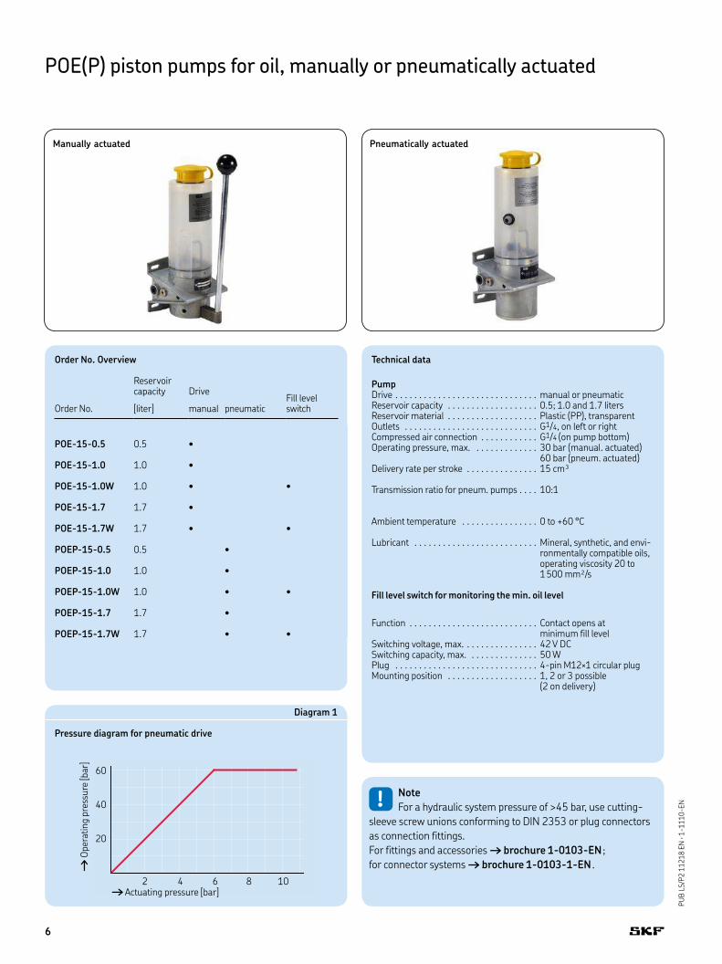
POE(P) piston pumps for oil, manually or pneumatically actuated
Technical data
PumpDrive . . . . . . . . . . . . . . . . . . . . . . . . . . . . . . manual or pneumaticReservoir capacity . . . . . . . . . . . . . . . . . . . 0.5; 1.0 and 1.7 litersReservoir material . . . . . . . . . . . . . . . . . . . Plastic (PP), transparentOutlets . . . . . . . . . . . . . . . . . . . . . . . . . . . . G1/4, on left or rightCompressed air connection . . . . . . . . . . . . G1/4 (on pump bottom)Operating pressure, max. . . . . . . . . . . . . . 30 bar (manual. actuated)
60 bar (pneum. actuated)Delivery rate per stroke . . . . . . . . . . . . . . . 15 cm³
Transmission ratio for pneum. pumps . . . . 10:1
Ambient temperature . . . . . . . . . . . . . . . . 0 to +60 °C
Lubricant . . . . . . . . . . . . . . . . . . . . . . . . . . Mineral, synthetic, and envi-ronmentally compatible oils, operating viscosity 20 to 1500 mm²/s
Fill level switch for monitoring the min. oil level
Function . . . . . . . . . . . . . . . . . . . . . . . . . . . Contact opens at minimum fill level
Switching voltage, max. . . . . . . . . . . . . . . . 42 V DCSwitching capacity, max. . . . . . . . . . . . . . . 50 WPlug . . . . . . . . . . . . . . . . . . . . . . . . . . . . . . 4-pin M12×1 circular plugMounting position . . . . . . . . . . . . . . . . . . . 1, 2 or 3 possible
(2 on delivery)
Diagram 1
Pressure diagram for pneumatic drive
60
40
20
2 4 6 8 10† Actuating pressure [bar]
† Op
erat
ing
pre
ssu
re [b
ar]
Order No. Overview
Reservoir capacity
Drive
Fill level switchOrder No. [liter] manual pneumatic
POE-15-0.5 0.5 •
POE-15-1.0 1.0 •
POE-15-1.0W 1.0 • •
POE-15-1.7 1.7 •
POE-15-1.7W 1.7 • •
POEP-15-0.5 0.5 •
POEP-15-1.0 1.0 •
POEP-15-1.0W 1.0 • •
POEP-15-1.7 1.7 •
POEP-15-1.7W 1.7 • •
!Note
For a hydraulic system pressure of >45 bar, use cutting-
sleeve screw unions conforming to DIN 2353 or plug connectors
as connection fittings.
For fittings and accessories † brochure 1-0103-EN;
for connector systems † brochure 1-0103-1-EN.
Pneumatically actuatedManually actuated
6
PU
B L
S/P
2 1
12
18
EN
· 1
-11
10
-EN
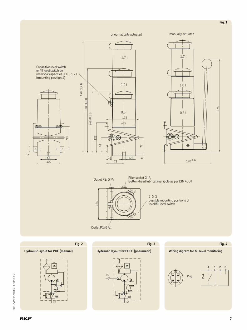
9
68100
90
G1/4
7323
ø95
133
7261
122
248
(0,5
l)33
8 (1
,0 l)
448
(1,7
l)
1,7 l
1,0 l
0,5 l
1,7 l
1,0 l
0,5 l
190
375
± 10
3
2
1
124
6
Filler socket G 1/4 Button-head lubricating nipple as per DIN 4304
Outlet P1: G 1/4
Outlet P2: G 1/4
Capacitive level switch or fill level switch on reservoir capacities: 1.0 l, 1.7 l (mounting position 1)
1 2 3 possible mounting positions of level/fill level switch
P2
Fig. 2
Hydraulic layout for POE (manual)
Fig. 4
Wiring digram for fill level monitoring
Fig. 1
pneumatically actuated manually actuated
P2
P1
Fig. 3
Hydraulic layout for POEP (pneumatic)
Plug
7
PU
B L
S/P
2 1
12
18
EN
· 1
-11
10
-EN
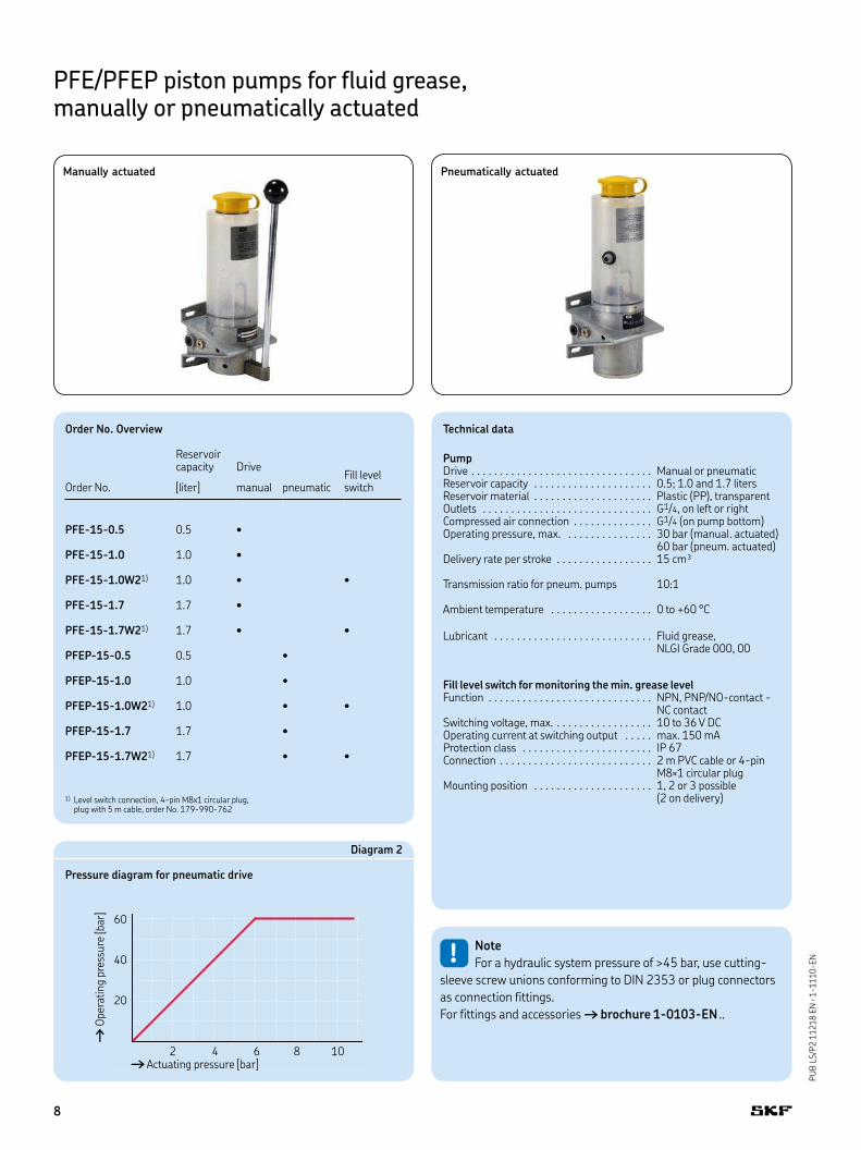
PFE/PFEP piston pumps for fluid grease, manually or pneumatically actuated
Technical data
PumpDrive . . . . . . . . . . . . . . . . . . . . . . . . . . . . . . . . Manual or pneumaticReservoir capacity . . . . . . . . . . . . . . . . . . . . . 0.5; 1.0 and 1.7 litersReservoir material . . . . . . . . . . . . . . . . . . . . . Plastic (PP), transparentOutlets . . . . . . . . . . . . . . . . . . . . . . . . . . . . . . G1/4, on left or rightCompressed air connection . . . . . . . . . . . . . . G1/4 (on pump bottom)Operating pressure, max. . . . . . . . . . . . . . . . 30 bar (manual. actuated)
60 bar (pneum. actuated)Delivery rate per stroke . . . . . . . . . . . . . . . . . 15 cm³
Transmission ratio for pneum. pumps 10:1
Ambient temperature . . . . . . . . . . . . . . . . . . 0 to +60 °C
Lubricant . . . . . . . . . . . . . . . . . . . . . . . . . . . . Fluid grease, NLGI Grade 000, 00
Fill level switch for monitoring the min. grease levelFunction . . . . . . . . . . . . . . . . . . . . . . . . . . . . . NPN, PNP/NO-contact -
NC contactSwitching voltage, max. . . . . . . . . . . . . . . . . . 10 to 36 V DCOperating current at switching output . . . . . max. 150 mAProtection class . . . . . . . . . . . . . . . . . . . . . . . IP 67Connection . . . . . . . . . . . . . . . . . . . . . . . . . . . 2 m PVC cable or 4-pin
M8×1 circular plugMounting position . . . . . . . . . . . . . . . . . . . . . 1, 2 or 3 possible
(2 on delivery)
Order No. Overview
Reservoir capacity Drive
Fill level switchOrder No. [liter] manual pneumatic
PFE-15-0.5 0.5 •
PFE-15-1.0 1.0 •
PFE-15-1.0W21) 1.0 • •
PFE-15-1.7 1.7 •
PFE-15-1.7W21) 1.7 • •
PFEP-15-0.5 0.5 •
PFEP-15-1.0 1.0 •
PFEP-15-1.0W21) 1.0 • •
PFEP-15-1.7 1.7 •
PFEP-15-1.7W21) 1.7 • •
1) Level switch connection, 4-pin M8x1 circular plug, plug with 5 m cable, order No. 179-990-762
Pneumatically actuatedManually actuated
Diagram 2
Pressure diagram for pneumatic drive
60
40
20
2 4 6 8 10† Actuating pressure [bar]
† Op
erat
ing
pre
ssu
re [b
ar]
!Note
For a hydraulic system pressure of >45 bar, use cutting-
sleeve screw unions conforming to DIN 2353 or plug connectors
as connection fittings.
For fittings and accessories † brochure 1-0103-EN..
8
PU
B L
S/P
2 1
12
18
EN
· 1
-11
10
-EN
68
1,7 l
1,0 l
0,5 l
9.
190G1/4
ø95
133
73
23100
124
375
7261
1222
48 (0,5 l)
338 (1,0 l)
448 (1,7 l)
90
± 10
1,7 l
1,0 l
0,5 l
3
2
1
6
P2
P1
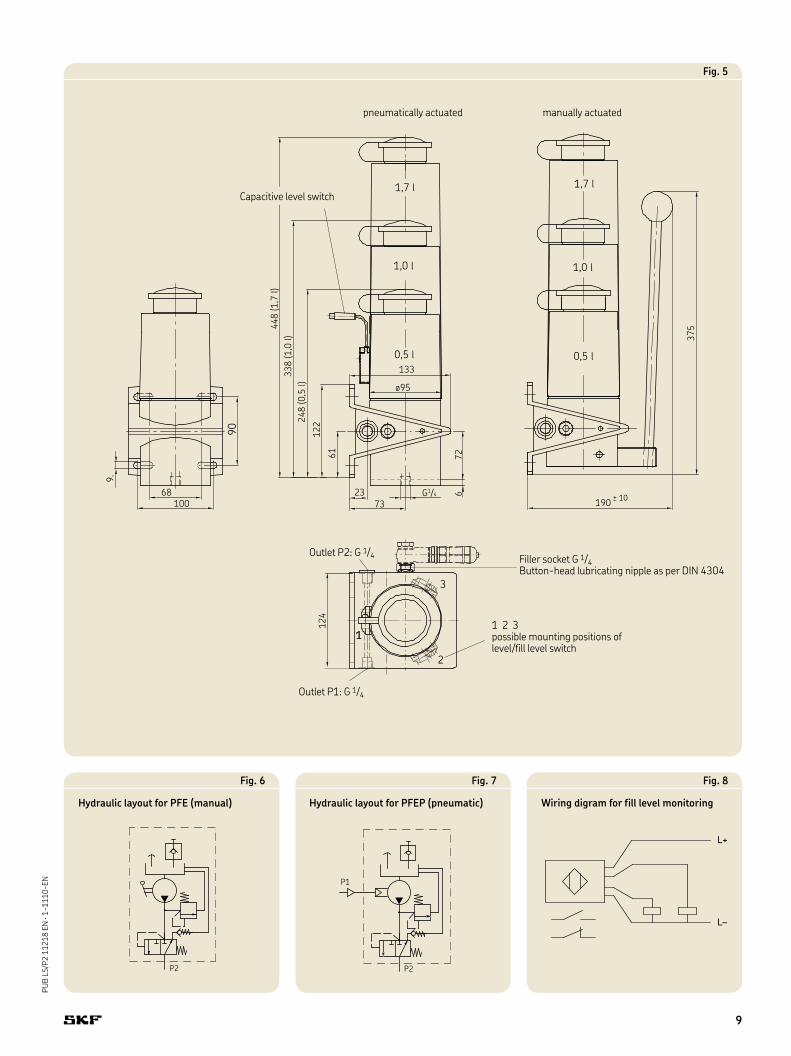
Fig. 7
Hydraulic layout for PFEP (pneumatic)
P2
Fig. 6
Hydraulic layout for PFE (manual)
L+
L–
Fig. 8
Wiring digram for fill level monitoring
Fig. 5
Filler socket G 1/4 Button-head lubricating nipple as per DIN 4304
Outlet P1: G 1/4
Outlet P2: G 1/4
Capacitive level switch
1 2 3 possible mounting positions of level/fill level switch
pneumatically actuated manually actuated
9
PU
B L
S/P
2 1
12
18
EN
· 1
-11
10
-EN
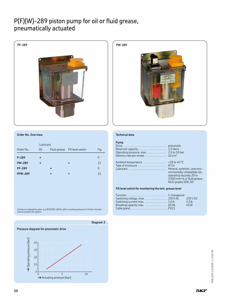
P(F)(W)-289 piston pump for oil or fluid grease, pneumatically actuated
PF-289 PW-289
Diagram 3
Pressure diagram for pneumatic drive
40
30
20
10
00 5 10† Actuating pressure [bar]
† Op
erat
ing
pre
ssu
re [b
ar]
Order No. Overview
Lubricant
Order No. Oil Fluid grease Fill level switch Fig.
P-289 • 9
PW-289 • • 11
PF-289 • 9
PFW-289 • • 11
A pressure regulating valve, e.g. WVN200-6B40, with a cracking pressure of 40 bar must be used to protect the system.
Technical data
PumpDrive . . . . . . . . . . . . . . . . . . . . . . . . . . . . . pneumaticReservoir capacity . . . . . . . . . . . . . . . . . . 1.5 litersOperating pressure, max. . . . . . . . . . . . . 3.5 to 10 barDelivery rate per stroke . . . . . . . . . . . . . . 10 cm³
Ambient temperature . . . . . . . . . . . . . . . +10 to 40 °CType of enclosure . . . . . . . . . . . . . . . . . . . IP 54Lubricant . . . . . . . . . . . . . . . . . . . . . . . . . Mineral, synthetic, and envi-
ronmentally compatible oils, operating viscosity 20 to 1000 mm²/s or fluid grease, NLGI grades 000, 00
Fill level switch for monitoring the min. grease level
Function . . . . . . . . . . . . . . . . . . . . . . . . . . . 1 changeoverSwitching voltage, max. . . . . . . . . . . . . . . . 230 V AC 230 V DCSwitching surrent max. . . . . . . . . . . . . . . . 1.0 A 1.0 ABreaking capacity max. . . . . . . . . . . . . . . . 60 VA 40 WCable gland . . . . . . . . . . . . . . . . . . . . . . . . . PG11
10
PU
B L
S/P
2 1
12
18
EN
· 1
-11
10
-EN
170
216
163
153
0
25
32
67.5
52
5835
G 1/4
M10×11)
7
7.5
3
128155
f. Rohr ø6
P1
P2
P2
P1
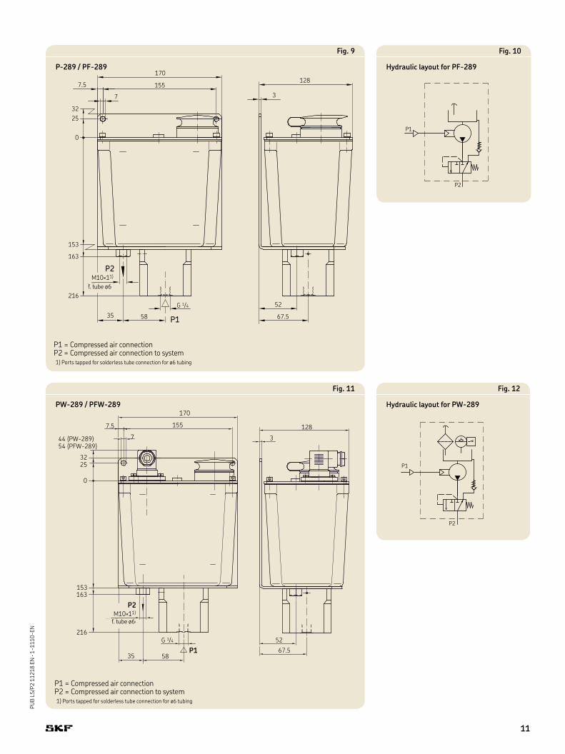
Fig. 12
Hydraulic layout for PW-289
Fig. 9
P-289 / PF-289
P2
P1
Fig. 10
Hydraulic layout for PF-289
P1 = Compressed air connectionP2 = Compressed air connection to system1) Ports tapped for solderless tube connection for ø6 tubing
f. tube ø6
67.5
52
3
170
1557.5
44 (PW-289)54 (PFW-289)
3225
153163
216
35 58
G 1/4
M10×11)
für Rohr ø6
P2
P1
128
0
7
P1 = Compressed air connectionP2 = Compressed air connection to system1) Ports tapped for solderless tube connection for ø6 tubing
Fig. 11
PW-289 / PFW-289
f. tube ø6
11
PU
B L
S/P
2 1
12
18
EN
· 1
-11
10
-EN
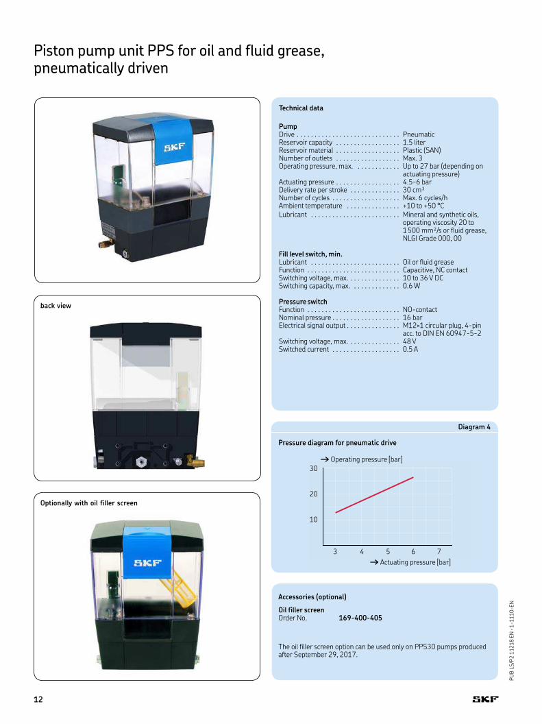
Piston pump unit PPS for oil and fluid grease, pneumatically driven
Diagram 4
Pressure diagram for pneumatic drive
30
20
10
3 4 5 6 7
† Actuating pressure [bar]
† Operating pressure [bar]
Technical data
PumpDrive . . . . . . . . . . . . . . . . . . . . . . . . . . . . . PneumaticReservoir capacity . . . . . . . . . . . . . . . . . . 1.5 literReservoir material . . . . . . . . . . . . . . . . . . Plastic (SAN)Number of outlets . . . . . . . . . . . . . . . . . . Max. 3Operating pressure, max. . . . . . . . . . . . . Up to 27 bar (depending on
actuating pressure)Actuating pressure . . . . . . . . . . . . . . . . . . 4.5-6 barDelivery rate per stroke . . . . . . . . . . . . . . 30 cm³Number of cycles . . . . . . . . . . . . . . . . . . . Max. 6 cycles/hAmbient temperature . . . . . . . . . . . . . . . +10 to +50 °CLubricant . . . . . . . . . . . . . . . . . . . . . . . . . Mineral and synthetic oils,
operating viscosity 20 to 1500 mm²/s or fluid grease, NLGI Grade 000, 00
Fill level switch, min.Lubricant . . . . . . . . . . . . . . . . . . . . . . . . . Oil or fluid greaseFunction . . . . . . . . . . . . . . . . . . . . . . . . . . Capacitive, NC contactSwitching voltage, max. . . . . . . . . . . . . . . 10 to 36 V DCSwitching capacity, max. . . . . . . . . . . . . . 0.6 W
Pressure switchFunction . . . . . . . . . . . . . . . . . . . . . . . . . . NO-contactNominal pressure . . . . . . . . . . . . . . . . . . . 16 barElectrical signal output . . . . . . . . . . . . . . . M12×1 circular plug, 4-pin
acc. to DIN EN 60947-5-2Switching voltage, max. . . . . . . . . . . . . . . 48 VSwitched current . . . . . . . . . . . . . . . . . . . 0.5 A
back view
Optionally with oil filler screen
Accessories (optional)
Oil filler screenOrder No. 169-400-405
The oil filler screen option can be used only on PPS30 pumps produced after September 29, 2017.
12
PU
B L
S/P
2 1
12
18
EN
· 1
-11
10
-EN
11.5
90.5
128.5
27
16
245.5
220
187
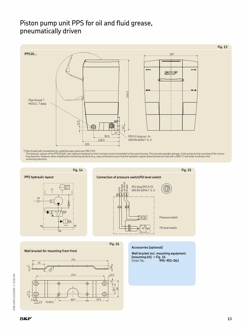
Fig. 13
PPS30...
214
35
193±2
80±0.1 59.5
10.5
10
930
±0.1
48
4x ø6.62.52.5
9+0.1
2
135°
Fig. 16
Wall bracket for mounting from frontAccessories (optional)
Wall bracket incl. mounting equipment (mounting kit) → Fig. 16Order No. 995-901-061
Pipe thread *) M10×1, 7 deep
P N P
WS
DS
BKBUBN
BU
BK
BN
WH
3 4 1 2XS2
0V DC
WS signa
l
+10–3
6V DC
DS signa
l
4
21
3
P
Fig. 15
Connection of pressure switch/fill level switch
P1
P2
P2
P216 bar
Fig. 14
PPS hydraulic layout
Piston pump unit PPS for oil and fluid grease, pneumatically driven
XS2 plug (M12×1): DIN EN 60947-5-2
Pressure switch
Fill level switch
M12×1 plug acc. to DIN EN 60947-5-2
*) Pipe thread with counterbore for solderless pipe unions per DIN 2353 The hydraulic outputs of the PPS30 (left, rear, right) are designed so that no torque can be transmitted to the pump housing. This prevents possible damage to the pump during mounting of the connec-ting elements. However, when installing the connecting elements (e.g., plug connector) ensure that the hydraulic outputs (external hex) are held with a WAF 17 tool while screwing in the connecting elements.
13
PU
B L
S/P
2 1
12
18
EN
· 1
-11
10
-EN
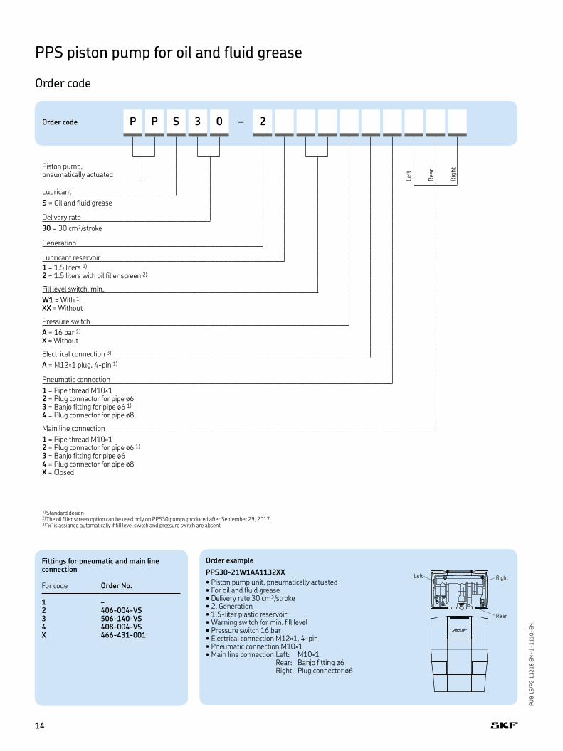
Order code P P S 3 0 – 2
Piston pump, pneumatically actuated
Lubricant
S = Oil and fluid grease
Delivery rate
30 = 30 cm³/stroke
Generation
Lubricant reservoir
1 = 1.5 liters 1)
2 = 1.5 liters with oil filler screen 2)
Fill level switch, min.
W1 = With 1) XX = Without
Pressure switch
A = 16 bar 1) X = Without
Electrical connection 3)
A = M12×1 plug, 4-pin 1)
Pneumatic connection
1 = Pipe thread M10×1 2 = Plug connector for pipe ø6 3 = Banjo fitting for pipe ø6 1) 4 = Plug connector for pipe ø8
Main line connection
1 = Pipe thread M10×1 2 = Plug connector for pipe ø6 1) 3 = Banjo fitting for pipe ø6 4 = Plug connector for pipe ø8 X = Closed
1) Standard design2) The oil filler screen option can be used only on PPS30 pumps produced after September 29, 2017. 3) “x” is assigned automatically if fill level switch and pressure switch are absent.
Left
Rig
ht
Rea
r
Order example
PPS30-21W1AA1132XX
• Piston pump unit, pneumatically actuated• For oil and fluid grease• Delivery rate 30 cm³/stroke• 2. Generation• 1.5-liter plastic reservoir• Warning switch for min. fill level• Pressure switch 16 bar• Electrical connection M12×1, 4-pin• Pneumatic connection M10×1• Main line connection Left: M10×1
Rear: Banjo fitting ø6 Right: Plug connector ø6
Fittings for pneumatic and main line connection
For code Order No.
1 –2 406-004-VS3 506-140-VS4 408-004-VSX 466-431-001
Left Right
Rear
PPS piston pump for oil and fluid grease
Order code
14
PU
B L
S/P
2 1
12
18
EN
· 1
-11
10
-EN
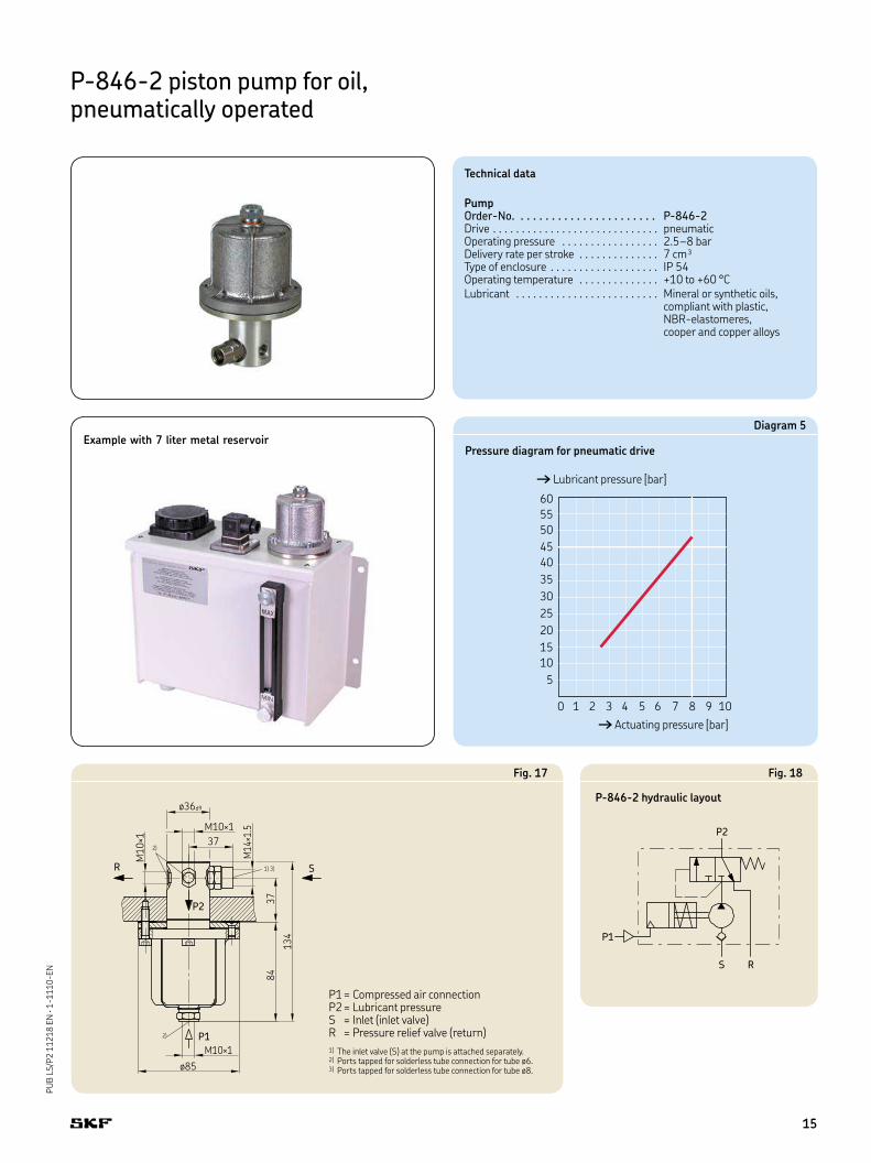
P-846-2 piston pump for oil, pneumatically operated
Technical data
PumpOrder-No. . . . . . . . . . . . . . . . . . . . . . . P-846-2Drive . . . . . . . . . . . . . . . . . . . . . . . . . . . . . pneumaticOperating pressure . . . . . . . . . . . . . . . . . 2.5–8 barDelivery rate per stroke . . . . . . . . . . . . . . 7 cm³Type of enclosure . . . . . . . . . . . . . . . . . . . IP 54Operating temperature . . . . . . . . . . . . . . +10 to +60 °CLubricant . . . . . . . . . . . . . . . . . . . . . . . . . Mineral or synthetic oils,
compliant with plastic, NBR-elastomeres, cooper and copper alloys
Diagram 5
Pressure diagram for pneumatic drive
60
55
50
45
40
35
30
25
20
15
10
5
0 1 2 3 4 5 6 7 8 9 10
† Actuating pressure [bar]
† Lubricant pressure [bar]
Example with 7 liter metal reservoir
ø36d9
M10×1
37
M10×1
M10×1
ø85
37
84
134
M14×1.5
1) 3)
2)
2)
R S
P1
P2
Fig. 17
P2
P1
S R
Fig. 18
P-846-2 hydraulic layout
P1 = Compressed air connectionP2 = Lubricant pressure S = Inlet (inlet valve) R = Pressure relief valve (return)
1) The inlet valve (S) at the pump is attached separately.2) Ports tapped for solderless tube connection for tube ø6.3) Ports tapped for solderless tube connection for tube ø8.
15
PU
B L
S/P
2 1
12
18
EN
· 1
-11
10
-EN
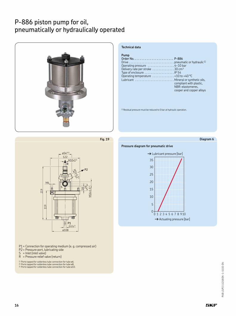
P-886 piston pump for oil, pneumatically or hydraulically operated
Technical data
PumpOrder No. . . . . . . . . . . . . . . . . . . . . . . . P-886Drive . . . . . . . . . . . . . . . . . . . . . . . . . . . . . pneumatic or hydraulic1)
Operating pressure . . . . . . . . . . . . . . . . . 4–10 barDelivery rate per stroke . . . . . . . . . . . . . . 30 cm³Type of enclosure . . . . . . . . . . . . . . . . . . . IP 54Operating temperature . . . . . . . . . . . . . . +10 to +40 °CLubricant . . . . . . . . . . . . . . . . . . . . . . . . . Mineral or synthetic oils,
compliant with plastic, NBR-elastomeres, cooper and copper alloys
1) Residual pressure must be reduced to 0 bar at hydraulic operation.
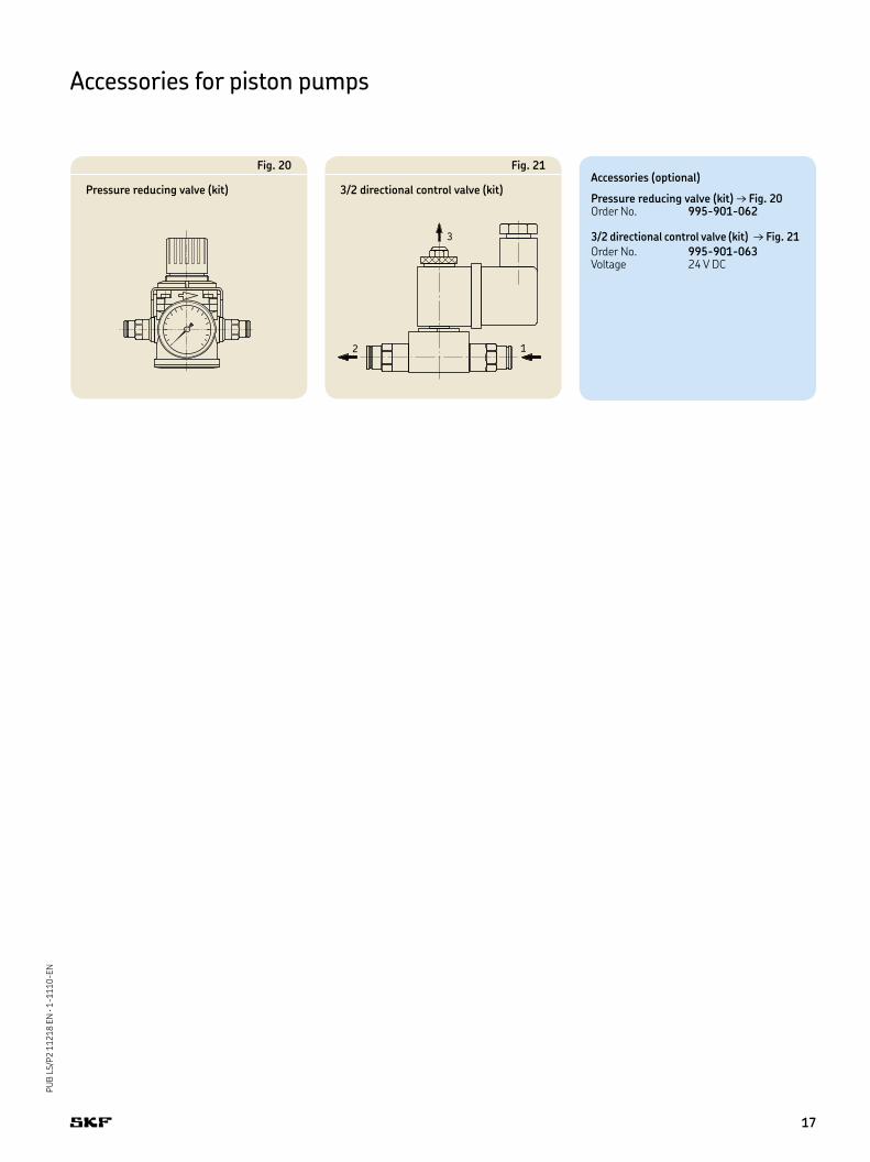
Diagram 6
Pressure diagram for pneumatic drive
0 1 2 3 4 5 6 7 8 9 10
35
30
25
20
15
10
5
0
† Actuating pressure [bar]
† Lubricant pressure [bar]
R
P1
P2
ø54H11
122M10×11)
M14×1.5
2)
ø108
G1/42)
M16×1.5
3)
18 29
M6
219
119
S
Fig. 19
P1 = Connection for operating medium (e. g. compressed air)P2 = Pressure port, lubricating side S = Inlet (inlet valve) R = Pressure relief valve (return)
1) Ports tapped for solderless tube connection for tube ø6.2) Ports tapped for solderless tube connection for tube ø8.3) Ports tapped for solderless tube connection for tube ø10.
16
PU
B L
S/P
2 1
12
18
EN
· 1
-11
10
-EN
Accessories (optional)
Pressure reducing valve (kit) → Fig. 20Order No. 995-901-062
3/2 directional control valve (kit) → Fig. 21
Order No. 995-901-063Voltage 24 V DC
Fig. 20
Pressure reducing valve (kit)
3
2 1
Fig. 21
3/2 directional control valve (kit)
Accessories for piston pumps
17
PU
B L
S/P
2 1
12
18
EN
· 1
-11
10
-EN
Notes
18

PU
B L
S/P
2 1
12
18
EN
· 1
-11
10
-EN
19
This brochure was presented by:
® SKF is a registered trademark of the SKF Group.
© SKF Group 2018The contents of this publication are the copyright of the publisher and may not be reproduced (even extracts) unless prior written permis-sion is granted. Every care has been taken to ensure the accuracy of the information contained in this publication but no liability can be accepted for any loss or damage whether direct, indirect or consequential arising out of the use of the information contained herein.
PUB LS/P2 11218 EN · January 2018 · 1-1110-EN
This publication supersedes publication 1-0015-EN · 1-1111-EN
SKF Lubrication Systems Germany GmbH
Motzener Strasse 35/37
12277 Berlin · Germany
PO Box 970444 · 12704 Berlin · Germany
Tel. +49 (0)30 72002-0
Fax +49 (0)30 72002-111
Further brochures
1-0103-EN Fittings and Accessories
1-1701-EN Pressure switches DSA, DSB, DSC, DSD
1-1702-EN Fill level switch WSx
1-1730-EN Electrical plug and socket connectors
1-5001-EN Lubricant distributors
1-9201-EN Transport of Lubricants in Centralized Lubrication Systems
skf.com/lubrication


![Type 231, 232, 233 Pneumatically Actuated Ball Valve...Type 233 Pneumatically Actuated Ball Valve With manual override With solvent cement sockets/threaded NPT Inch Cv-value [gal/min]](https://img.pdfslide.us/doc/110x75/5f8932caaaacc31e734d8cd7/type-231-232-233-pneumatically-actuated-ball-valve-type-233-pneumatically.jpg)