Embed Size (px)
Citation preview

1
9 LD 561-29 LD 561-2/L9 LD 625-2
WORK SHOPMANUAL
9 LD series Engine, code 1-5302-286
2nd edition
COMPILER TECO/ATL REG. CODE
1-5302-286
MODEL N°
50494
DATE OF ISSUE
06-88REVISION 01
ENDORSEDDATE
30.03.2003

PREFACE
Every attempt has been made to present within this service manual, accurate and up to date technical information.However, development on the Lombardini series is continuos. Therefore, the information within this manual is subjectto change without notice and without obligation.
The information contained within this service manual is the sole property of Lombardini. As such, no reproduction orreplication in whole or part is allowed without the express written permission of Lombardini.
Information presented within this manual assumes the following:
1- The person or persons performing service work on Lombardini series engines is properly trained and equipped tosafely and professionally perform the subject operation;
2- The person or persons performing service work on Lombardini series engines possesses adequate hand andLombardini special tools to safely and professionally perform the subject service operation;
3- The person or persons performing service work on Lombardini series engines has read the pertinent informationregarding the subject service operations and fully understands the operation at hand.
GENERAL SERVICE MANUAL NOTES:
1- Use only genuine Lombardini repair parts. Failure to use genuine Lombardini parts could result in sub-standardperformance and low longevity.
2- All data presented are in metric format. That is, dimensions are presented in millimeters (mm), torque is presentedin Newton-meters (Nm), weight is presented in kilograms (Kg), volume is presented in liters or cubic centimeters(cc) and pressure is presented in barometric units (bar).
3COMPILER TECO/ATL REG. CODE
1-5302-286
MODEL N°
50494
DATE OF ISSUE
06-88REVISION 01
ENDORSEDDATE
30.03.2003
WARRANTY CERTIFICATE
The products manufactured by Lombardini Srl are warranted to be free from conformity defects for a periodof 24 months from the date of delivery to the first end user.For engines fitted to stationary equipment, working at constant load and at constant and/or slightly variablespeed within the setting limits, the warranty covers a period up to a limit of 2000 working hours, if the abovementioned period (24 months) is not expired.If no hour-meter is fitted , 12 working hours per calendar day will be considered.For what concerns the parts subject to wear and deterioration (injection/feeding system, electrical system,cooling system, sealing parts, non-metallic pipes, belts) warranty covers a maximum limit of 2000 workinghours, if the above mentioned period (24 months) is not expired.For correct maintenance and replacement of these parts, it is necessary to follow the instructions reportedin the documentation supplied with each engine.To ensure the engine warranty is valid, the engine installation, considering the product technical features,must be carried out by qualified personnel only.The list of the Lombardini authorized dealers is reported in the “Service” booklet, supplied with each engine.Special applications involving considerable modifications to the cooling/lubricating system (for ex.: dry oilsump), filtering system, turbo-charged models, will require special written warranty agreements.Within the above stated periods Lombardini Srl directly or through its authorized network will repair and/orreplace free of charge any own part or component that, upon examination by Lombardini or by an authorizedLombardini agent, is found to be defective in conformity, workmanship or materials.Any other responsibility/obligation for different expenses, damages and direct/indirect losses deriving fromthe engine use or from both the total or partial impossibility of use, is excluded.The repair or replacement of any component will not extend or renew the warranty period.
Lombardini warranty obligations here above described will be cancelled if:
- Lombardini engines are not correctly installed and as a consequence the correct functional parametersare not respected and altered.
- Lombardini engines are not used according to the instructions reported in the “Use and Maintenance”booklet supplied with each engine.
- Any seal affixed to the engine by Lombardini has been tampered with or removed.- Spare parts used are not original Lombardini.- Feeding and injection systems are damaged by unauthorized or poor quality fuel types.- Electrical system failure is due to components, connected to this system, which are not supplied or
installed by Lombardini.- Engines have been disassembled, repaired or altered by any part other than an authorized Lombardini
agent.
Following expiration of the above stated warranty periods and working hours, Lombardini will have no furtherresponsibility for warranty and will consider its here above mentioned obligations for warranty complete.Any warranty request related to a non-conformity of the product must be addressed to the Lombardini Srlservice agents.
WARRANTY CERTIFICATE

4COMPILER TECO/ATL REG. CODE
1-5302-286
MODEL N°
50494
DATE OF ISSUE
06-88REVISION 01
ENDORSEDDATE
30.03.2003
TABLE OF CONTENTS
I TROUBLESHOOTING
II SAFETY DECALS - SAFETY INSTRUCTIONS
III MODEL NUMBER AND IDENTIFICATION
IV TECHNICAL DATA
V CHARACTERISTIC CURVES
VI OVERALL DIMENSIONS
VII MAINTENANCE- RECOMMENDED OIL TYPE - REFILLING
VIII DISASSEMBLY / REASSEMBLY
0il vapour separator0il-bath air cleanerAlternatorCAMSHAFTCamshaft end playCamshaft timingChecking main journals and crank pinsChecks and cylinder roughnessClearance between main journals/crank pins and connecting rod bearings (mm)Clogging indicatorCompression release (optional)CONNECTING RODConnecting rod alignmentConnecting rod big end bearingConnecting rod small end bushingConnecting rod weightCooling fanCRANKSHAFTCrankshaft center main bearing supportCrankshaft end playCrankshaft journal radiiCrankshaft lubrication ductsCrankshaft removalCrankshaft timing gearCYLINDERCYLINDER HEADDimensions and clearance between guides and valves (mm)Dimensions of camshaft journals and housings (mm)Dry air cleanerELECTRONIC SPEED GOVERNORElectronic speed governorElectronic speed governor control boxElectronic speed governor layoutEngine running with electronic speed governorExhaust manifoldFlywheelGovernor springs with rocker arm
Pag. 9
" 10-11
" 12
" 13
" 15
" 16-17
" 18-19
" 21-45
22212439404036303722253233333233233535383636353430262839214444454445232543
○ ○ ○ ○ ○ ○ ○ ○ ○ ○ ○ ○ ○ ○ ○ ○ ○ ○ ○ ○ ○ ○ ○ ○ ○ ○ ○ ○ ○ ○ ○ ○ ○ ○ ○ ○ ○ ○ ○ ○ ○ ○ ○ ○ ○ ○ ○ ○
○ ○ ○ ○ ○ ○ ○ ○ ○ ○ ○ ○ ○ ○ ○ ○ ○ ○ ○ ○ ○ ○ ○ ○ ○ ○ ○ ○ ○ ○ ○ ○ ○ ○ ○ ○ ○ ○ ○ ○ ○ ○ ○ ○ ○ ○ ○ ○ ○
○ ○ ○ ○ ○ ○ ○ ○ ○ ○ ○ ○ ○ ○ ○ ○ ○ ○ ○ ○ ○ ○ ○ ○ ○ ○ ○ ○ ○ ○ ○ ○ ○ ○ ○ ○ ○ ○ ○ ○ ○ ○ ○ ○ ○ ○ ○ ○ ○ ○ ○ ○ ○ ○
○ ○ ○ ○ ○ ○ ○ ○ ○ ○ ○ ○ ○ ○ ○ ○ ○ ○ ○ ○ ○ ○ ○ ○ ○ ○ ○ ○ ○ ○ ○ ○ ○ ○ ○ ○ ○ ○ ○ ○ ○ ○ ○ ○ ○ ○ ○ ○ ○ ○ ○ ○
○ ○ ○ ○ ○ ○ ○ ○ ○ ○ ○ ○ ○ ○ ○ ○ ○ ○ ○ ○ ○ ○ ○ ○ ○ ○ ○ ○ ○ ○ ○ ○ ○ ○ ○ ○ ○ ○ ○ ○ ○ ○ ○ ○ ○ ○ ○ ○
○ ○ ○ ○ ○ ○ ○ ○ ○ ○ ○ ○ ○ ○ ○ ○ ○ ○ ○ ○ ○ ○ ○ ○ ○ ○ ○ ○ ○ ○ ○ ○ ○ ○ ○ ○ ○ ○ ○ ○ ○ ○ ○ ○ ○ ○ ○ ○ ○ ○
○ ○ ○ ○ ○ ○ ○ ○ ○ ○ ○ ○ ○ ○ ○ ○ ○ ○ ○ ○ ○ ○ ○ ○ ○ ○ ○ ○ ○ ○ ○ ○ ○ ○ ○ ○ ○ ○ ○ ○ ○ ○
○ ○ ○ ○ ○ ○ ○ ○ ○ ○ ○ ○ ○ ○ ○ ○ ○ ○ ○ ○ ○ ○ ○ ○ ○ ○ ○ ○ ○ ○ ○ ○ ○ ○ ○ ○ ○ ○ ○ ○ ○ ○ ○ ○ ○ ○ ○
○ ○ ○ ○ ○ ○ ○ ○ ○ ○ ○ ○ ○ ○ ○ ○ ○ ○ ○ ○ ○ ○ ○ ○ ○ ○ ○ ○ ○ ○ ○ ○ ○ ○ ○ ○ ○ ○ ○ ○ ○ ○ ○ ○ ○ ○ ○ ○ ○ ○ ○ ○
○ ○ ○ ○ ○ ○ ○ ○ ○ ○ ○ ○ ○ ○ ○ ○ ○ ○ ○ ○ ○ ○ ○ ○ ○ ○ ○ ○ ○ ○ ○ ○ ○ ○ ○ ○ ○ ○ ○ ○ ○ ○ ○ ○ ○ ○ ○ ○ ○ ○ ○
○ ○ ○ ○ ○ ○ ○ ○ ○ ○ ○ ○ ○ ○ ○ ○ ○ ○ ○ ○ ○ ○ ○ ○ ○ ○ ○ ○ ○ ○ ○ ○ ○ ○ ○ ○ ○
○ ○ ○ ○ ○ ○ ○ ○ ○ ○ ○ ○ ○ ○ ○ ○ ○ ○ ○ ○ ○ ○ ○ ○ ○ ○ ○ ○ ○ ○ ○ ○ ○ ○ ○ ○ ○ ○ ○ ○ ○ ○ ○ ○ ○ ○ ○ ○
○ ○ ○ ○ ○ ○ ○ ○ ○ ○ ○ ○ ○ ○ ○ ○ ○ ○ ○ ○ ○ ○ ○ ○ ○ ○ ○ ○ ○ ○ ○ ○ ○ ○ ○ ○ ○ ○ ○ ○ ○ ○ ○ ○ ○ ○
○ ○ ○ ○ ○ ○ ○ ○ ○ ○ ○ ○ ○ ○ ○ ○ ○ ○ ○ ○ ○ ○ ○ ○ ○ ○ ○ ○ ○ ○ ○ ○ ○ ○ ○ ○ ○ ○ ○ ○ ○ ○ ○ ○
○ ○ ○ ○ ○ ○ ○ ○ ○ ○ ○ ○ ○ ○ ○ ○ ○ ○ ○ ○ ○ ○ ○ ○ ○ ○ ○ ○ ○ ○ ○ ○ ○ ○ ○ ○ ○ ○ ○ ○ ○ ○ ○ ○ ○ ○ ○ ○ ○ ○ ○ ○ ○
○ ○ ○ ○ ○ ○ ○ ○ ○ ○ ○ ○ ○ ○ ○ ○ ○ ○ ○ ○ ○ ○ ○ ○ ○ ○ ○ ○ ○ ○ ○ ○ ○ ○ ○ ○ ○ ○ ○ ○ ○ ○ ○ ○ ○ ○ ○ ○
○ ○ ○ ○ ○ ○ ○ ○ ○ ○ ○ ○ ○ ○ ○ ○ ○ ○ ○ ○ ○ ○ ○ ○ ○ ○ ○ ○ ○ ○ ○ ○ ○ ○ ○ ○ ○ ○ ○ ○ ○ ○ ○ ○ ○ ○ ○ ○ ○ ○
○ ○ ○ ○ ○ ○ ○ ○ ○ ○ ○ ○ ○ ○ ○ ○ ○ ○ ○ ○ ○ ○ ○ ○ ○ ○ ○
○ ○ ○ ○ ○ ○ ○ ○ ○ ○ ○ ○ ○ ○ ○ ○ ○ ○ ○ ○ ○ ○ ○ ○ ○ ○ ○ ○ ○ ○
○ ○ ○ ○ ○ ○ ○ ○ ○ ○ ○ ○ ○ ○ ○ ○ ○ ○ ○ ○ ○ ○ ○ ○ ○ ○ ○ ○ ○ ○ ○ ○ ○ ○ ○ ○ ○ ○ ○ ○ ○ ○ ○ ○ ○ ○ ○ ○ ○ ○ ○
○ ○ ○ ○ ○ ○ ○ ○ ○ ○ ○ ○ ○ ○ ○ ○ ○ ○ ○ ○ ○ ○ ○ ○ ○ ○ ○ ○ ○ ○ ○ ○ ○ ○ ○ ○ ○ ○ ○
○ ○ ○ ○ ○ ○ ○ ○ ○ ○ ○ ○ ○ ○ ○ ○ ○ ○ ○ ○ ○ ○ ○ ○ ○ ○ ○ ○ ○ ○ ○ ○ ○ ○ ○ ○ ○ ○ ○ ○ ○ ○ ○ ○ ○
○ ○ ○ ○ ○ ○ ○ ○ ○ ○ ○ ○ ○ ○ ○ ○ ○ ○ ○ ○ ○ ○ ○ ○ ○ ○ ○ ○ ○ ○ ○ ○ ○ ○ ○ ○ ○ ○ ○ ○
○ ○ ○ ○ ○ ○ ○ ○ ○ ○ ○ ○ ○ ○ ○ ○ ○ ○ ○ ○ ○ ○ ○ ○ ○ ○ ○ ○ ○ ○ ○ ○ ○ ○ ○ ○ ○ ○ ○ ○ ○
○ ○ ○ ○ ○ ○ ○ ○ ○ ○ ○ ○ ○ ○ ○ ○ ○ ○ ○ ○ ○ ○ ○ ○ ○ ○ ○ ○ ○ ○ ○ ○ ○ ○
○ ○ ○ ○ ○ ○ ○ ○ ○ ○ ○ ○ ○ ○ ○ ○ ○ ○ ○ ○ ○ ○ ○ ○ ○ ○ ○ ○ ○ ○ ○ ○ ○ ○ ○ ○ ○ ○ ○ ○ ○ ○ ○ ○ ○ ○ ○ ○ ○ ○
○ ○ ○ ○ ○ ○ ○ ○ ○ ○ ○ ○ ○ ○ ○ ○ ○ ○ ○ ○ ○ ○ ○ ○ ○ ○ ○ ○ ○ ○ ○ ○ ○ ○ ○ ○ ○ ○ ○ ○ ○ ○ ○ ○ ○ ○ ○ ○ ○ ○ ○ ○ ○ ○
○ ○ ○ ○ ○ ○ ○ ○ ○ ○ ○ ○ ○ ○ ○ ○ ○ ○ ○ ○ ○ ○ ○ ○ ○ ○ ○ ○ ○ ○ ○ ○ ○ ○ ○ ○ ○ ○ ○ ○ ○
○ ○ ○ ○ ○ ○ ○ ○ ○ ○ ○ ○ ○ ○ ○ ○ ○ ○ ○ ○ ○ ○ ○ ○ ○ ○ ○ ○ ○ ○ ○ ○ ○ ○ ○ ○ ○ ○ ○ ○ ○ ○ ○ ○ ○ ○ ○
○ ○ ○ ○ ○ ○ ○ ○ ○ ○ ○ ○ ○ ○ ○ ○ ○ ○ ○ ○ ○ ○ ○ ○ ○ ○ ○ ○ ○ ○ ○ ○ ○ ○ ○ ○ ○ ○ ○ ○
○ ○ ○ ○ ○ ○ ○ ○ ○ ○ ○ ○ ○ ○ ○ ○ ○ ○ ○ ○ ○ ○ ○ ○ ○ ○ ○ ○ ○ ○ ○ ○ ○ ○ ○ ○ ○ ○ ○ ○ ○ ○ ○ ○ ○
○ ○ ○ ○ ○ ○ ○ ○ ○ ○ ○ ○ ○ ○ ○ ○ ○ ○ ○ ○ ○ ○ ○ ○ ○ ○ ○ ○ ○ ○ ○ ○ ○ ○ ○ ○ ○ ○ ○ ○ ○ ○ ○ ○ ○ ○ ○ ○
○ ○ ○ ○ ○ ○ ○ ○ ○ ○ ○ ○ ○ ○ ○ ○ ○ ○ ○ ○ ○ ○ ○ ○ ○ ○ ○ ○ ○ ○ ○ ○ ○ ○ ○ ○ ○ ○ ○ ○ ○ ○
○ ○ ○ ○ ○ ○ ○ ○ ○ ○ ○ ○ ○ ○ ○ ○ ○ ○ ○ ○ ○ ○ ○ ○ ○ ○ ○ ○ ○ ○ ○ ○ ○ ○ ○ ○ ○ ○ ○ ○ ○ ○ ○ ○ ○ ○ ○ ○ ○
○ ○ ○ ○ ○ ○ ○ ○ ○ ○ ○ ○ ○ ○ ○ ○ ○
○ ○ ○ ○ ○ ○ ○ ○ ○ ○ ○ ○ ○ ○ ○ ○ ○ ○ ○ ○ ○ ○ ○ ○ ○ ○ ○ ○ ○ ○ ○ ○ ○ ○ ○ ○ ○ ○ ○ ○ ○ ○
○ ○ ○ ○ ○ ○ ○ ○ ○ ○ ○ ○ ○ ○ ○ ○ ○ ○ ○ ○ ○ ○ ○ ○ ○ ○ ○ ○ ○ ○ ○ ○ ○ ○ ○ ○ ○ ○
This manual contains pertinent information regarding the repair of LOMBARDINI air-cooled, directinjection Diesel engines type 9 LD 561-2, 9 LD 561-2/L, 9 LD 625-2: updated March 30, 2003.
INTRODUCTION
5COMPILER TECO/ATL REG. CODE
1-5302-286
MODEL N°
50494
DATE OF ISSUE
06-88REVISION 01
ENDORSEDDATE
30.03.2003
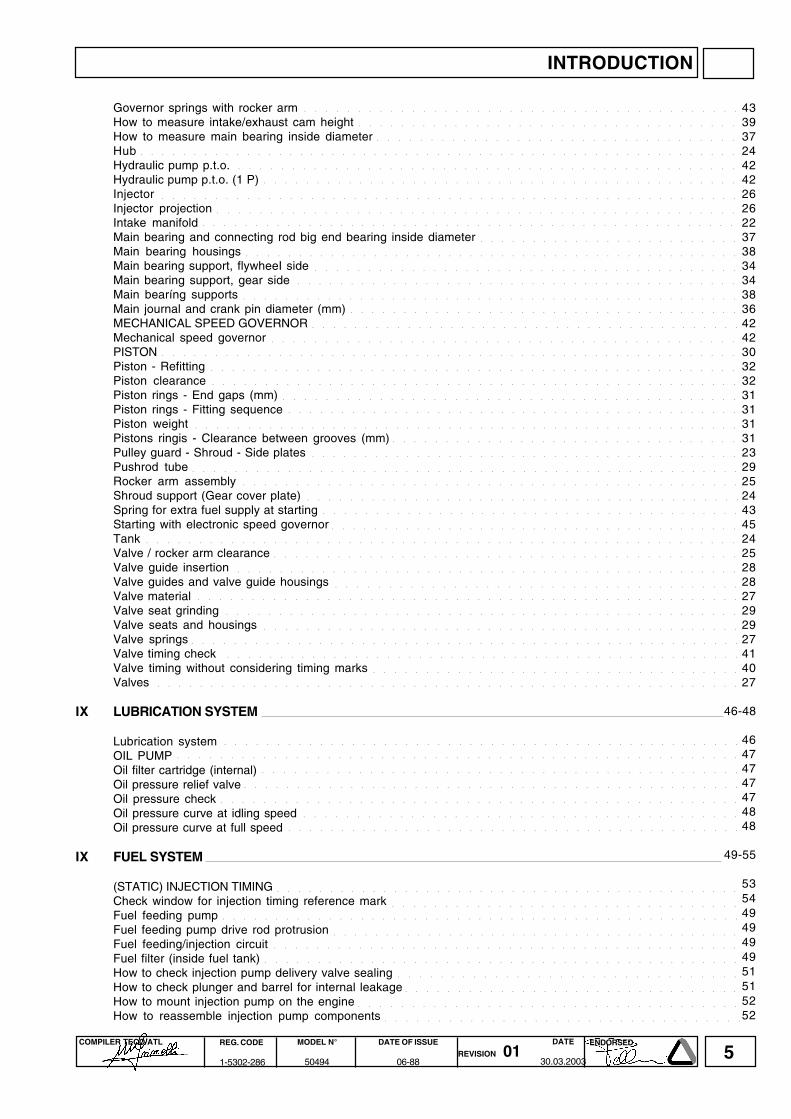
Governor springs with rocker armHow to measure intake/exhaust cam heightHow to measure main bearing inside diameterHubHydraulic pump p.t.o.Hydraulic pump p.t.o. (1 P)InjectorInjector projectionIntake manifoldMain bearing and connecting rod big end bearing inside diameterMain bearing housingsMain bearing support, flywheeI sideMain bearing support, gear sideMain bearíng supportsMain journal and crank pin diameter (mm)MECHANICAL SPEED GOVERNORMechanical speed governorPISTONPiston - RefittingPiston clearancePiston rings - End gaps (mm)Piston rings - Fitting sequencePiston weightPistons ringis - Clearance between grooves (mm)Pulley guard - Shroud - Side platesPushrod tubeRocker arm assemblyShroud support (Gear cover plate)Spring for extra fuel supply at startingStarting with electronic speed governorTankValve / rocker arm clearanceValve guide insertionValve guides and valve guide housingsValve materialValve seat grindingValve seats and housingsValve springsValve timing checkValve timing without considering timing marksValves
IX LUBRICATION SYSTEM
Lubrication systemOIL PUMPOil filter cartridge (internal)Oil pressure relief valveOil pressure checkOil pressure curve at idling speedOil pressure curve at full speed
IX FUEL SYSTEM
(STATIC) INJECTION TIMINGCheck window for injection timing reference markFuel feeding pumpFuel feeding pump drive rod protrusionFuel feeding/injection circuitFuel filter (inside fuel tank)How to check injection pump delivery valve sealingHow to check plunger and barrel for internal leakageHow to mount injection pump on the engineHow to reassemble injection pump components
4339372442422626223738343438364242303232313131312329252443452425282827292927414027
46-48
46474747474848
49-55
53544949494951515252
○ ○ ○ ○ ○ ○ ○ ○ ○ ○ ○ ○ ○ ○ ○ ○ ○ ○ ○ ○ ○ ○ ○ ○ ○ ○ ○ ○ ○ ○ ○ ○ ○ ○ ○ ○ ○ ○ ○ ○ ○
○ ○ ○ ○ ○ ○ ○ ○ ○ ○ ○ ○ ○ ○ ○ ○ ○ ○ ○ ○ ○ ○ ○ ○ ○ ○ ○ ○ ○ ○ ○ ○ ○ ○ ○ ○
○ ○ ○ ○ ○ ○ ○ ○ ○ ○ ○ ○ ○ ○ ○ ○ ○ ○ ○ ○ ○ ○ ○ ○ ○ ○ ○ ○ ○ ○ ○ ○ ○ ○
○ ○ ○ ○ ○ ○ ○ ○ ○ ○ ○ ○ ○ ○ ○ ○ ○ ○ ○ ○ ○ ○ ○ ○ ○ ○ ○ ○ ○ ○ ○ ○ ○ ○ ○ ○ ○ ○ ○ ○ ○ ○ ○ ○ ○ ○ ○ ○ ○ ○ ○ ○ ○ ○ ○ ○ ○
○ ○ ○ ○ ○ ○ ○ ○ ○ ○ ○ ○ ○ ○ ○ ○ ○ ○ ○ ○ ○ ○ ○ ○ ○ ○ ○ ○ ○ ○ ○ ○ ○ ○ ○ ○ ○ ○ ○ ○ ○ ○ ○ ○ ○ ○ ○
○ ○ ○ ○ ○ ○ ○ ○ ○ ○ ○ ○ ○ ○ ○ ○ ○ ○ ○ ○ ○ ○ ○ ○ ○ ○ ○ ○ ○ ○ ○ ○ ○ ○ ○ ○ ○ ○ ○ ○ ○ ○ ○ ○ ○
○ ○ ○ ○ ○ ○ ○ ○ ○ ○ ○ ○ ○ ○ ○ ○ ○ ○ ○ ○ ○ ○ ○ ○ ○ ○ ○ ○ ○ ○ ○ ○ ○ ○ ○ ○ ○ ○ ○ ○ ○ ○ ○ ○ ○ ○ ○ ○ ○ ○ ○ ○ ○ ○ ○
○ ○ ○ ○ ○ ○ ○ ○ ○ ○ ○ ○ ○ ○ ○ ○ ○ ○ ○ ○ ○ ○ ○ ○ ○ ○ ○ ○ ○ ○ ○ ○ ○ ○ ○ ○ ○ ○ ○ ○ ○ ○ ○ ○ ○ ○ ○ ○ ○
○ ○ ○ ○ ○ ○ ○ ○ ○ ○ ○ ○ ○ ○ ○ ○ ○ ○ ○ ○ ○ ○ ○ ○ ○ ○ ○ ○ ○ ○ ○ ○ ○ ○ ○ ○ ○ ○ ○ ○ ○ ○ ○ ○ ○ ○ ○ ○ ○ ○ ○
○ ○ ○ ○ ○ ○ ○ ○ ○ ○ ○ ○ ○ ○ ○ ○ ○ ○ ○ ○ ○ ○ ○ ○ ○
○ ○ ○ ○ ○ ○ ○ ○ ○ ○ ○ ○ ○ ○ ○ ○ ○ ○ ○ ○ ○ ○ ○ ○ ○ ○ ○ ○ ○ ○ ○ ○ ○ ○ ○ ○ ○ ○ ○ ○ ○ ○ ○ ○ ○ ○ ○
○ ○ ○ ○ ○ ○ ○ ○ ○ ○ ○ ○ ○ ○ ○ ○ ○ ○ ○ ○ ○ ○ ○ ○ ○ ○ ○ ○ ○ ○ ○ ○ ○ ○ ○ ○ ○ ○ ○ ○
○ ○ ○ ○ ○ ○ ○ ○ ○ ○ ○ ○ ○ ○ ○ ○ ○ ○ ○ ○ ○ ○ ○ ○ ○ ○ ○ ○ ○ ○ ○ ○ ○ ○ ○ ○ ○ ○ ○ ○ ○ ○
○ ○ ○ ○ ○ ○ ○ ○ ○ ○ ○ ○ ○ ○ ○ ○ ○ ○ ○ ○ ○ ○ ○ ○ ○ ○ ○ ○ ○ ○ ○ ○ ○ ○ ○ ○ ○ ○ ○ ○ ○ ○ ○ ○ ○ ○ ○
○ ○ ○ ○ ○ ○ ○ ○ ○ ○ ○ ○ ○ ○ ○ ○ ○ ○ ○ ○ ○ ○ ○ ○ ○ ○ ○ ○ ○ ○ ○ ○ ○ ○ ○ ○ ○
○ ○ ○ ○ ○ ○ ○ ○ ○ ○ ○ ○ ○ ○ ○ ○ ○ ○ ○ ○ ○ ○ ○ ○ ○ ○ ○ ○ ○ ○ ○ ○ ○ ○ ○ ○ ○ ○ ○ ○ ○
○ ○ ○ ○ ○ ○ ○ ○ ○ ○ ○ ○ ○ ○ ○ ○ ○ ○ ○ ○ ○ ○ ○ ○ ○ ○ ○ ○ ○ ○ ○ ○ ○ ○ ○ ○ ○ ○ ○ ○ ○ ○ ○ ○
○ ○ ○ ○ ○ ○ ○ ○ ○ ○ ○ ○ ○ ○ ○ ○ ○ ○ ○ ○ ○ ○ ○ ○ ○ ○ ○ ○ ○ ○ ○ ○ ○ ○ ○ ○ ○ ○ ○ ○ ○ ○ ○ ○ ○ ○ ○ ○ ○ ○ ○ ○ ○ ○ ○
○ ○ ○ ○ ○ ○ ○ ○ ○ ○ ○ ○ ○ ○ ○ ○ ○ ○ ○ ○ ○ ○ ○ ○ ○ ○ ○ ○ ○ ○ ○ ○ ○ ○ ○ ○ ○ ○ ○ ○ ○ ○ ○ ○ ○ ○ ○ ○ ○ ○
○ ○ ○ ○ ○ ○ ○ ○ ○ ○ ○ ○ ○ ○ ○ ○ ○ ○ ○ ○ ○ ○ ○ ○ ○ ○ ○ ○ ○ ○ ○ ○ ○ ○ ○ ○ ○ ○ ○ ○ ○ ○ ○
○ ○ ○ ○ ○ ○ ○ ○ ○ ○ ○ ○ ○ ○ ○ ○ ○ ○ ○ ○ ○ ○ ○ ○ ○ ○ ○ ○ ○ ○ ○ ○ ○ ○ ○ ○ ○ ○ ○ ○ ○ ○ ○
○ ○ ○ ○ ○ ○ ○ ○ ○ ○ ○ ○ ○ ○ ○ ○ ○ ○ ○ ○ ○ ○ ○ ○ ○ ○ ○ ○ ○ ○ ○ ○ ○ ○ ○ ○ ○ ○ ○ ○ ○ ○ ○ ○ ○ ○ ○ ○ ○ ○
○ ○ ○ ○ ○ ○ ○ ○ ○ ○ ○ ○ ○ ○ ○ ○ ○ ○ ○ ○ ○ ○ ○ ○ ○ ○ ○ ○ ○ ○ ○ ○ ○ ○ ○ ○ ○ ○ ○ ○ ○ ○ ○ ○ ○ ○ ○ ○ ○ ○ ○ ○
○ ○ ○ ○ ○ ○ ○ ○ ○ ○ ○ ○ ○ ○ ○ ○ ○ ○ ○ ○ ○ ○ ○ ○ ○ ○ ○ ○ ○ ○ ○ ○ ○
○ ○ ○ ○ ○ ○ ○ ○ ○ ○ ○ ○ ○ ○ ○ ○ ○ ○ ○ ○ ○ ○ ○ ○ ○ ○ ○ ○ ○ ○ ○ ○ ○ ○ ○ ○ ○ ○ ○ ○ ○
○ ○ ○ ○ ○ ○ ○ ○ ○ ○ ○ ○ ○ ○ ○ ○ ○ ○ ○ ○ ○ ○ ○ ○ ○ ○ ○ ○ ○ ○ ○ ○ ○ ○ ○ ○ ○ ○ ○ ○ ○ ○ ○ ○ ○ ○ ○ ○ ○ ○ ○ ○
○ ○ ○ ○ ○ ○ ○ ○ ○ ○ ○ ○ ○ ○ ○ ○ ○ ○ ○ ○ ○ ○ ○ ○ ○ ○ ○ ○ ○ ○ ○ ○ ○ ○ ○ ○ ○ ○ ○ ○ ○ ○ ○ ○ ○ ○ ○
○ ○ ○ ○ ○ ○ ○ ○ ○ ○ ○ ○ ○ ○ ○ ○ ○ ○ ○ ○ ○ ○ ○ ○ ○ ○ ○ ○ ○ ○ ○ ○ ○ ○ ○ ○ ○ ○ ○ ○ ○
○ ○ ○ ○ ○ ○ ○ ○ ○ ○ ○ ○ ○ ○ ○ ○ ○ ○ ○ ○ ○ ○ ○ ○ ○ ○ ○ ○ ○ ○ ○ ○ ○ ○ ○ ○ ○ ○ ○ ○
○ ○ ○ ○ ○ ○ ○ ○ ○ ○ ○ ○ ○ ○ ○ ○ ○ ○ ○ ○ ○ ○ ○ ○ ○ ○ ○ ○ ○ ○ ○ ○ ○ ○ ○ ○ ○ ○ ○
○ ○ ○ ○ ○ ○ ○ ○ ○ ○ ○ ○ ○ ○ ○ ○ ○ ○ ○ ○ ○ ○ ○ ○ ○ ○ ○ ○ ○ ○ ○ ○ ○ ○ ○ ○ ○ ○ ○ ○ ○ ○ ○ ○ ○ ○ ○ ○ ○ ○ ○ ○ ○ ○ ○ ○
○ ○ ○ ○ ○ ○ ○ ○ ○ ○ ○ ○ ○ ○ ○ ○ ○ ○ ○ ○ ○ ○ ○ ○ ○ ○ ○ ○ ○ ○ ○ ○ ○ ○ ○ ○ ○ ○ ○ ○ ○ ○ ○ ○
○ ○ ○ ○ ○ ○ ○ ○ ○ ○ ○ ○ ○ ○ ○ ○ ○ ○ ○ ○ ○ ○ ○ ○ ○ ○ ○ ○ ○ ○ ○ ○ ○ ○ ○ ○ ○ ○ ○ ○ ○ ○ ○ ○ ○ ○ ○ ○
○ ○ ○ ○ ○ ○ ○ ○ ○ ○ ○ ○ ○ ○ ○ ○ ○ ○ ○ ○ ○ ○ ○ ○ ○ ○ ○ ○ ○ ○ ○ ○ ○ ○ ○ ○ ○ ○
○ ○ ○ ○ ○ ○ ○ ○ ○ ○ ○ ○ ○ ○ ○ ○ ○ ○ ○ ○ ○ ○ ○ ○ ○ ○ ○ ○ ○ ○ ○ ○ ○ ○ ○ ○ ○ ○ ○ ○ ○ ○ ○ ○ ○ ○ ○ ○ ○ ○ ○
○ ○ ○ ○ ○ ○ ○ ○ ○ ○ ○ ○ ○ ○ ○ ○ ○ ○ ○ ○ ○ ○ ○ ○ ○ ○ ○ ○ ○ ○ ○ ○ ○ ○ ○ ○ ○ ○ ○ ○ ○ ○ ○ ○ ○ ○ ○ ○ ○
○ ○ ○ ○ ○ ○ ○ ○ ○ ○ ○ ○ ○ ○ ○ ○ ○ ○ ○ ○ ○ ○ ○ ○ ○ ○ ○ ○ ○ ○ ○ ○ ○ ○ ○ ○ ○ ○ ○ ○ ○ ○ ○ ○ ○
○ ○ ○ ○ ○ ○ ○ ○ ○ ○ ○ ○ ○ ○ ○ ○ ○ ○ ○ ○ ○ ○ ○ ○ ○ ○ ○ ○ ○ ○ ○ ○ ○ ○ ○ ○ ○ ○ ○ ○ ○ ○ ○ ○ ○ ○ ○ ○ ○ ○ ○ ○
○ ○ ○ ○ ○ ○ ○ ○ ○ ○ ○ ○ ○ ○ ○ ○ ○ ○ ○ ○ ○ ○ ○ ○ ○ ○ ○ ○ ○ ○ ○ ○ ○ ○ ○ ○ ○ ○ ○ ○ ○ ○ ○ ○ ○ ○ ○ ○ ○
○ ○ ○ ○ ○ ○ ○ ○ ○ ○ ○ ○ ○ ○ ○ ○ ○ ○ ○ ○ ○ ○ ○ ○ ○ ○ ○ ○ ○ ○ ○ ○ ○ ○ ○
○ ○ ○ ○ ○ ○ ○ ○ ○ ○ ○ ○ ○ ○ ○ ○ ○ ○ ○ ○ ○ ○ ○ ○ ○ ○ ○ ○ ○ ○ ○ ○ ○ ○ ○ ○ ○ ○ ○ ○ ○ ○ ○ ○ ○ ○ ○ ○ ○ ○ ○ ○ ○ ○ ○
○ ○ ○ ○ ○ ○ ○ ○ ○ ○ ○ ○ ○ ○ ○ ○ ○ ○ ○ ○ ○ ○ ○ ○ ○ ○ ○ ○ ○ ○ ○ ○ ○ ○ ○ ○ ○ ○ ○ ○ ○ ○ ○ ○ ○ ○ ○ ○ ○
○ ○ ○ ○ ○ ○ ○ ○ ○ ○ ○ ○ ○ ○ ○ ○ ○ ○ ○ ○ ○ ○ ○ ○ ○ ○ ○ ○ ○ ○ ○ ○ ○ ○ ○ ○ ○ ○ ○ ○ ○ ○ ○ ○ ○ ○ ○ ○ ○ ○ ○ ○ ○
○ ○ ○ ○ ○ ○ ○ ○ ○ ○ ○ ○ ○ ○ ○ ○ ○ ○ ○ ○ ○ ○ ○ ○ ○ ○ ○ ○ ○ ○ ○ ○ ○ ○ ○ ○ ○ ○ ○ ○ ○ ○ ○ ○ ○
○ ○ ○ ○ ○ ○ ○ ○ ○ ○ ○ ○ ○ ○ ○ ○ ○ ○ ○ ○ ○ ○ ○ ○ ○ ○ ○ ○ ○ ○ ○ ○ ○ ○ ○ ○ ○ ○ ○ ○ ○ ○ ○ ○ ○ ○ ○
○ ○ ○ ○ ○ ○ ○ ○ ○ ○ ○ ○ ○ ○ ○ ○ ○ ○ ○ ○ ○ ○ ○ ○ ○ ○ ○ ○ ○ ○ ○ ○ ○ ○ ○ ○ ○ ○ ○ ○ ○ ○ ○ ○ ○ ○ ○ ○ ○
○ ○ ○ ○ ○ ○ ○ ○ ○ ○ ○ ○ ○ ○ ○ ○ ○ ○ ○ ○ ○ ○ ○ ○ ○ ○ ○ ○ ○ ○ ○ ○ ○ ○ ○ ○ ○ ○ ○ ○ ○
○ ○ ○ ○ ○ ○ ○ ○ ○ ○ ○ ○ ○ ○ ○ ○ ○ ○ ○ ○ ○ ○ ○ ○ ○ ○ ○ ○ ○ ○ ○ ○ ○ ○ ○ ○ ○ ○ ○ ○ ○ ○ ○
○ ○ ○ ○ ○ ○ ○ ○ ○ ○ ○ ○ ○ ○ ○ ○ ○ ○ ○ ○ ○ ○ ○ ○ ○ ○ ○ ○ ○ ○ ○ ○ ○ ○ ○ ○ ○ ○ ○ ○ ○ ○ ○ ○
○ ○ ○ ○ ○ ○ ○ ○ ○ ○ ○ ○ ○ ○ ○ ○ ○ ○ ○ ○ ○ ○ ○ ○ ○ ○ ○ ○ ○ ○ ○ ○ ○ ○ ○ ○ ○ ○ ○
○ ○ ○ ○ ○ ○ ○ ○ ○ ○ ○ ○ ○ ○ ○ ○ ○ ○ ○ ○ ○ ○ ○ ○ ○ ○ ○ ○ ○ ○ ○ ○ ○ ○ ○ ○ ○ ○ ○ ○ ○ ○ ○ ○ ○ ○ ○ ○ ○
○ ○ ○ ○ ○ ○ ○ ○ ○ ○ ○ ○ ○ ○ ○ ○ ○ ○ ○ ○ ○ ○ ○ ○ ○ ○ ○ ○ ○ ○ ○ ○ ○ ○ ○ ○ ○ ○ ○ ○ ○ ○ ○ ○ ○
○ ○ ○ ○ ○ ○ ○ ○ ○ ○ ○ ○ ○ ○ ○ ○ ○ ○ ○ ○ ○ ○ ○ ○ ○ ○ ○ ○ ○ ○ ○ ○
○ ○ ○ ○ ○ ○ ○ ○ ○ ○ ○ ○ ○ ○ ○ ○ ○ ○ ○ ○ ○ ○ ○ ○ ○ ○ ○ ○ ○ ○ ○ ○
○ ○ ○ ○ ○ ○ ○ ○ ○ ○ ○ ○ ○ ○ ○ ○ ○ ○ ○ ○ ○ ○ ○ ○ ○ ○ ○ ○ ○ ○ ○ ○ ○ ○ ○ ○ ○ ○ ○ ○ ○ ○ ○ ○
○ ○ ○ ○ ○ ○ ○ ○ ○ ○ ○ ○ ○ ○ ○ ○ ○ ○ ○ ○ ○ ○ ○ ○ ○ ○ ○ ○ ○ ○ ○ ○ ○
○ ○ ○ ○ ○ ○ ○ ○ ○ ○ ○ ○ ○ ○ ○ ○ ○ ○ ○ ○ ○ ○ ○ ○ ○ ○ ○ ○ ○ ○ ○ ○ ○ ○ ○ ○
○ ○ ○ ○ ○ ○ ○ ○ ○ ○ ○ ○ ○ ○ ○ ○ ○ ○ ○ ○ ○ ○ ○ ○ ○ ○ ○ ○ ○ ○ ○ ○ ○ ○
INTRODUCTION
6COMPILER TECO/ATL REG. CODE
1-5302-286
MODEL N°
50494
DATE OF ISSUE
06-88REVISION 01
ENDORSEDDATE
30.03.2003
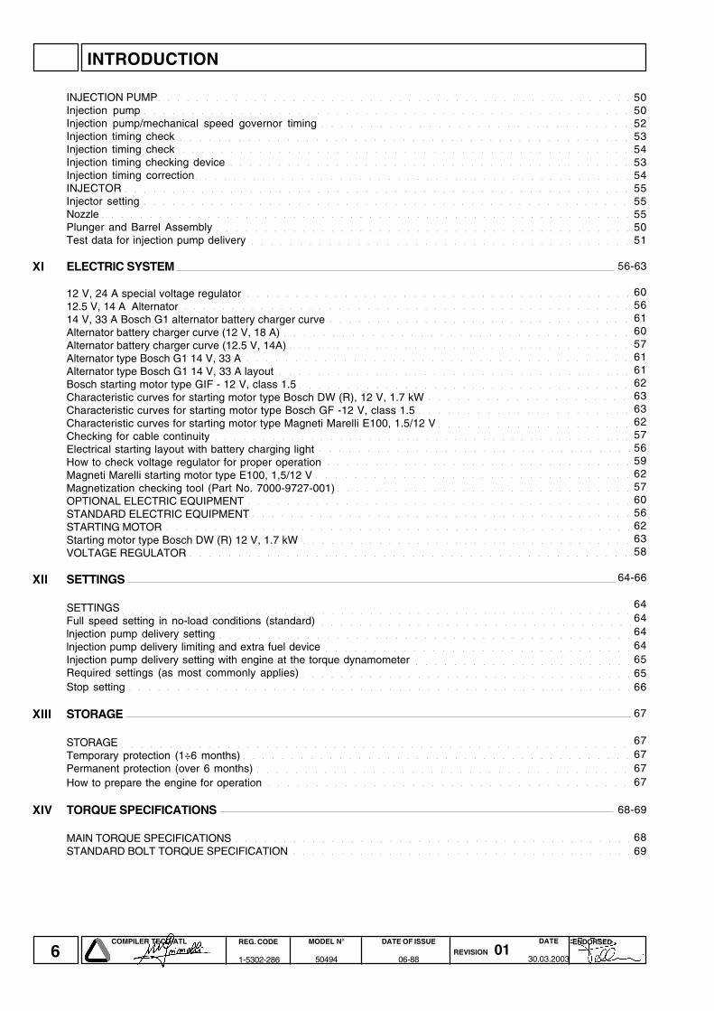
INJECTION PUMPInjection pumpInjection pump/mechanical speed governor timingInjection timing checkInjection timing checkInjection timing checking deviceInjection timing correctionINJECTORInjector settingNozzlePlunger and Barrel AssemblyTest data for injection pump delivery
XI ELECTRIC SYSTEM
12 V, 24 A special voltage regulator12.5 V, 14 A Alternator14 V, 33 A Bosch G1 alternator battery charger curveAlternator battery charger curve (12 V, 18 A)Alternator battery charger curve (12.5 V, 14A)Alternator type Bosch G1 14 V, 33 AAlternator type Bosch G1 14 V, 33 A layoutBosch starting motor type GIF - 12 V, class 1.5Characteristic curves for starting motor type Bosch DW (R), 12 V, 1.7 kWCharacteristic curves for starting motor type Bosch GF -12 V, class 1.5Characteristic curves for starting motor type Magneti Marelli E100, 1.5/12 VChecking for cable continuityElectrical starting layout with battery charging lightHow to check voltage regulator for proper operationMagneti Marelli starting motor type E100, 1,5/12 VMagnetization checking tool (Part No. 7000-9727-001)OPTIONAL ELECTRIC EQUIPMENTSTANDARD ELECTRIC EQUIPMENTSTARTING MOTORStarting motor type Bosch DW (R) 12 V, 1.7 kWVOLTAGE REGULATOR
XII SETTINGS
SETTINGSFull speed setting in no-load conditions (standard)lnjection pump delivery settinglnjection pump delivery limiting and extra fuel deviceInjection pump delivery setting with engine at the torque dynamometerRequired settings (as most commonly applies)Stop setting
XIII STORAGE
STORAGETemporary protection (1÷6 months)Permanent protection (over 6 months)How to prepare the engine for operation
XIV TORQUE SPECIFICATIONS
MAIN TORQUE SPECIFICATIONSSTANDARD BOLT TORQUE SPECIFICATION
505052535453545555555051
56-63
605661605761616263636257565962576056626358
64-66
64646464656566
67
67676767
68-69
6869
○ ○ ○ ○ ○ ○ ○ ○ ○ ○ ○ ○ ○ ○ ○ ○ ○ ○ ○ ○ ○ ○ ○ ○ ○ ○ ○ ○ ○ ○ ○ ○ ○ ○ ○ ○ ○ ○ ○ ○ ○ ○ ○ ○ ○ ○ ○ ○ ○ ○
○ ○ ○ ○ ○ ○ ○ ○ ○ ○ ○ ○ ○ ○ ○ ○ ○ ○ ○ ○ ○ ○ ○ ○ ○ ○ ○ ○ ○ ○ ○ ○ ○ ○ ○ ○ ○ ○ ○ ○ ○ ○ ○ ○ ○ ○ ○ ○ ○ ○ ○
○ ○ ○ ○ ○ ○ ○ ○ ○ ○ ○ ○ ○ ○ ○ ○ ○ ○ ○ ○ ○ ○ ○ ○ ○ ○ ○ ○ ○ ○ ○ ○
○ ○ ○ ○ ○ ○ ○ ○ ○ ○ ○ ○ ○ ○ ○ ○ ○ ○ ○ ○ ○ ○ ○ ○ ○ ○ ○ ○ ○ ○ ○ ○ ○ ○ ○ ○ ○ ○ ○ ○ ○ ○ ○ ○ ○ ○ ○
○ ○ ○ ○ ○ ○ ○ ○ ○ ○ ○ ○ ○ ○ ○ ○ ○ ○ ○ ○ ○ ○ ○ ○ ○ ○ ○ ○ ○ ○ ○ ○ ○ ○ ○ ○ ○ ○ ○ ○ ○ ○ ○ ○ ○ ○ ○
○ ○ ○ ○ ○ ○ ○ ○ ○ ○ ○ ○ ○ ○ ○ ○ ○ ○ ○ ○ ○ ○ ○ ○ ○ ○ ○ ○ ○ ○ ○ ○ ○ ○ ○ ○ ○ ○ ○ ○ ○ ○
○ ○ ○ ○ ○ ○ ○ ○ ○ ○ ○ ○ ○ ○ ○ ○ ○ ○ ○ ○ ○ ○ ○ ○ ○ ○ ○ ○ ○ ○ ○ ○ ○ ○ ○ ○ ○ ○ ○ ○ ○ ○ ○ ○ ○ ○
○ ○ ○ ○ ○ ○ ○ ○ ○ ○ ○ ○ ○ ○ ○ ○ ○ ○ ○ ○ ○ ○ ○ ○ ○ ○ ○ ○ ○ ○ ○ ○ ○ ○ ○ ○ ○ ○ ○ ○ ○ ○ ○ ○ ○ ○ ○ ○ ○ ○ ○ ○ ○
○ ○ ○ ○ ○ ○ ○ ○ ○ ○ ○ ○ ○ ○ ○ ○ ○ ○ ○ ○ ○ ○ ○ ○ ○ ○ ○ ○ ○ ○ ○ ○ ○ ○ ○ ○ ○ ○ ○ ○ ○ ○ ○ ○ ○ ○ ○ ○ ○ ○ ○
○ ○ ○ ○ ○ ○ ○ ○ ○ ○ ○ ○ ○ ○ ○ ○ ○ ○ ○ ○ ○ ○ ○ ○ ○ ○ ○ ○ ○ ○ ○ ○ ○ ○ ○ ○ ○ ○ ○ ○ ○ ○ ○ ○ ○ ○ ○ ○ ○ ○ ○ ○ ○ ○ ○ ○
○ ○ ○ ○ ○ ○ ○ ○ ○ ○ ○ ○ ○ ○ ○ ○ ○ ○ ○ ○ ○ ○ ○ ○ ○ ○ ○ ○ ○ ○ ○ ○ ○ ○ ○ ○ ○ ○ ○ ○ ○ ○ ○ ○
○ ○ ○ ○ ○ ○ ○ ○ ○ ○ ○ ○ ○ ○ ○ ○ ○ ○ ○ ○ ○ ○ ○ ○ ○ ○ ○ ○ ○ ○ ○ ○ ○ ○ ○ ○ ○ ○ ○ ○
○ ○ ○ ○ ○ ○ ○ ○ ○ ○ ○ ○ ○ ○ ○ ○ ○ ○ ○ ○ ○ ○ ○ ○ ○ ○ ○ ○ ○ ○ ○ ○ ○ ○ ○ ○ ○ ○ ○ ○
○ ○ ○ ○ ○ ○ ○ ○ ○ ○ ○ ○ ○ ○ ○ ○ ○ ○ ○ ○ ○ ○ ○ ○ ○ ○ ○ ○ ○ ○ ○ ○ ○ ○ ○ ○ ○ ○ ○ ○ ○ ○ ○ ○ ○ ○ ○
○ ○ ○ ○ ○ ○ ○ ○ ○ ○ ○ ○ ○ ○ ○ ○ ○ ○ ○ ○ ○ ○ ○ ○ ○ ○ ○ ○ ○ ○ ○ ○
○ ○ ○ ○ ○ ○ ○ ○ ○ ○ ○ ○ ○ ○ ○ ○ ○ ○ ○ ○ ○ ○ ○ ○ ○ ○ ○ ○ ○ ○ ○ ○ ○ ○ ○ ○
○ ○ ○ ○ ○ ○ ○ ○ ○ ○ ○ ○ ○ ○ ○ ○ ○ ○ ○ ○ ○ ○ ○ ○ ○ ○ ○ ○ ○ ○ ○ ○ ○ ○ ○ ○
○ ○ ○ ○ ○ ○ ○ ○ ○ ○ ○ ○ ○ ○ ○ ○ ○ ○ ○ ○ ○ ○ ○ ○ ○ ○ ○ ○ ○ ○ ○ ○ ○ ○ ○ ○ ○ ○ ○ ○
○ ○ ○ ○ ○ ○ ○ ○ ○ ○ ○ ○ ○ ○ ○ ○ ○ ○ ○ ○ ○ ○ ○ ○ ○ ○ ○ ○ ○ ○ ○ ○ ○ ○ ○ ○ ○
○ ○ ○ ○ ○ ○ ○ ○ ○ ○ ○ ○ ○ ○ ○ ○ ○ ○ ○ ○ ○ ○ ○ ○ ○ ○ ○ ○ ○ ○ ○ ○ ○ ○ ○
○ ○ ○ ○ ○ ○ ○ ○ ○ ○ ○ ○ ○ ○ ○ ○ ○ ○ ○ ○ ○
○ ○ ○ ○ ○ ○ ○ ○ ○ ○ ○ ○ ○ ○ ○ ○ ○ ○ ○ ○ ○ ○
○ ○ ○ ○ ○ ○ ○ ○ ○ ○ ○ ○ ○ ○ ○ ○ ○ ○ ○ ○
○ ○ ○ ○ ○ ○ ○ ○ ○ ○ ○ ○ ○ ○ ○ ○ ○ ○ ○ ○ ○ ○ ○ ○ ○ ○ ○ ○ ○ ○ ○ ○ ○ ○ ○ ○ ○ ○ ○ ○ ○ ○ ○ ○
○ ○ ○ ○ ○ ○ ○ ○ ○ ○ ○ ○ ○ ○ ○ ○ ○ ○ ○ ○ ○ ○ ○ ○ ○ ○ ○ ○ ○ ○ ○ ○ ○
○ ○ ○ ○ ○ ○ ○ ○ ○ ○ ○ ○ ○ ○ ○ ○ ○ ○ ○ ○ ○ ○ ○ ○ ○ ○ ○ ○ ○ ○ ○ ○
○ ○ ○ ○ ○ ○ ○ ○ ○ ○ ○ ○ ○ ○ ○ ○ ○ ○ ○ ○ ○ ○ ○ ○ ○ ○ ○ ○ ○ ○ ○ ○ ○
○ ○ ○ ○ ○ ○ ○ ○ ○ ○ ○ ○ ○ ○ ○ ○ ○ ○ ○ ○ ○ ○ ○ ○ ○ ○ ○ ○ ○ ○ ○
○ ○ ○ ○ ○ ○ ○ ○ ○ ○ ○ ○ ○ ○ ○ ○ ○ ○ ○ ○ ○ ○ ○ ○ ○ ○ ○ ○ ○ ○ ○ ○ ○ ○ ○ ○ ○ ○ ○ ○
○ ○ ○ ○ ○ ○ ○ ○ ○ ○ ○ ○ ○ ○ ○ ○ ○ ○ ○ ○ ○ ○ ○ ○ ○ ○ ○ ○ ○ ○ ○ ○ ○ ○ ○ ○ ○ ○ ○ ○
○ ○ ○ ○ ○ ○ ○ ○ ○ ○ ○ ○ ○ ○ ○ ○ ○ ○ ○ ○ ○ ○ ○ ○ ○ ○ ○ ○ ○ ○ ○ ○ ○ ○ ○ ○ ○ ○ ○ ○ ○ ○ ○ ○ ○ ○ ○ ○ ○
○ ○ ○ ○ ○ ○ ○ ○ ○ ○ ○ ○ ○ ○ ○ ○ ○ ○ ○ ○ ○ ○ ○ ○ ○ ○ ○ ○ ○ ○ ○ ○ ○ ○ ○
○ ○ ○ ○ ○ ○ ○ ○ ○ ○ ○ ○ ○ ○ ○ ○ ○ ○ ○ ○ ○ ○ ○ ○ ○ ○ ○ ○ ○ ○ ○ ○ ○ ○ ○ ○ ○ ○ ○ ○ ○ ○ ○ ○ ○ ○
○ ○ ○ ○ ○ ○ ○ ○ ○ ○ ○ ○ ○ ○ ○ ○ ○ ○ ○ ○ ○ ○ ○ ○ ○ ○ ○ ○ ○ ○ ○ ○ ○ ○ ○ ○ ○ ○ ○ ○ ○ ○ ○ ○ ○ ○ ○ ○ ○ ○ ○ ○ ○ ○
○ ○ ○ ○ ○ ○ ○ ○ ○ ○ ○ ○ ○ ○ ○ ○ ○ ○ ○ ○ ○ ○ ○ ○ ○ ○ ○ ○ ○ ○ ○ ○ ○
○ ○ ○ ○ ○ ○ ○ ○ ○ ○ ○ ○ ○ ○ ○ ○ ○ ○ ○ ○ ○ ○ ○ ○ ○ ○ ○ ○ ○ ○ ○ ○ ○ ○ ○ ○ ○ ○ ○ ○ ○ ○ ○
○ ○ ○ ○ ○ ○ ○ ○ ○ ○ ○ ○ ○ ○ ○ ○ ○ ○ ○ ○ ○ ○ ○ ○ ○ ○ ○ ○ ○ ○ ○ ○
○ ○ ○ ○ ○ ○ ○ ○ ○ ○ ○ ○ ○ ○ ○ ○ ○ ○ ○ ○ ○ ○ ○
○ ○ ○ ○ ○ ○ ○ ○ ○ ○ ○ ○ ○ ○ ○ ○ ○ ○ ○ ○ ○ ○ ○ ○ ○ ○ ○ ○ ○ ○ ○ ○ ○ ○ ○
○ ○ ○ ○ ○ ○ ○ ○ ○ ○ ○ ○ ○ ○ ○ ○ ○ ○ ○ ○ ○ ○ ○ ○ ○ ○ ○ ○ ○ ○ ○ ○ ○ ○ ○ ○ ○ ○ ○ ○ ○ ○ ○ ○ ○ ○ ○ ○ ○ ○ ○ ○ ○
○ ○ ○ ○ ○ ○ ○ ○ ○ ○ ○ ○ ○ ○ ○ ○ ○ ○ ○ ○ ○ ○ ○ ○ ○ ○ ○ ○ ○ ○ ○ ○ ○ ○ ○ ○ ○ ○ ○ ○ ○ ○ ○ ○ ○ ○ ○ ○ ○ ○ ○ ○ ○
○ ○ ○ ○ ○ ○ ○ ○ ○ ○ ○ ○ ○ ○ ○ ○ ○ ○ ○ ○ ○ ○ ○ ○ ○ ○ ○ ○ ○ ○ ○ ○ ○ ○ ○ ○ ○ ○ ○ ○ ○
○ ○ ○ ○ ○ ○ ○ ○ ○ ○ ○ ○ ○ ○ ○ ○ ○ ○ ○ ○ ○ ○ ○ ○ ○ ○ ○ ○ ○ ○ ○ ○ ○ ○ ○ ○ ○ ○ ○
○ ○ ○ ○ ○ ○ ○ ○ ○ ○ ○ ○ ○ ○ ○ ○ ○ ○ ○ ○ ○ ○ ○ ○ ○ ○ ○ ○ ○ ○ ○ ○ ○ ○ ○ ○ ○ ○
○ ○ ○ ○ ○ ○ ○ ○ ○ ○ ○ ○ ○ ○ ○ ○ ○ ○ ○ ○ ○ ○ ○ ○ ○ ○ ○ ○ ○ ○ ○ ○ ○ ○ ○ ○ ○ ○ ○ ○ ○ ○
○ ○ ○ ○ ○ ○ ○ ○ ○ ○ ○ ○ ○ ○ ○ ○ ○ ○ ○ ○ ○ ○ ○ ○ ○ ○ ○ ○ ○ ○ ○ ○ ○ ○ ○ ○
INTRODUCTION

7COMPILER TECO/ATL REG. CODE
1-5302-286
MODEL N°
50494
DATE OF ISSUE
06-88REVISION 01
ENDORSEDDATE
30.03.2003
NOTE

8COMPILER TECO/ATL REG. CODE
1-5302-286
MODEL N°
50494
DATE OF ISSUE
06-88REVISION 01
ENDORSEDDATE
30.03.2003
NOTE

9COMPILER TECO/ATL REG. CODE
1-5302-286
MODEL N°
50494
DATE OF ISSUE
06-88REVISION 01
ENDORSEDDATE
30.03.2003
I
The following table contains the possible cause of some failures which may occur during operation. Alwaysperform the simplest checks before removing or replacing any part.
POSSIBLE CAUSE
Too
low
oil
pres
sure
With
e sm
oke
Bla
ck s
mok
e
Non
uni
form
spe
ed
No
acce
lera
tion
Eng
ine
star
tsbu
t st
ops
Eng
ine
does
not
star
t
Clogged pipingsClogged fuel filterAir inside fuel circuitClogged tank breatherFaulty feed pumpStuck injectorStuck injection pump valveWrong injector settingSticking injection pump rackWrong injection pump setting
Too high oil levelStuck pressure relief valveIncorrect relief valve settingWorn-oil pumpAir inside oil suction pipeFaulty pressure gauge or switchClogged oil suction pipeBattery dis-chargedWrong or inefficient cable connectionDefective starter switchDefective starter
Clogged air filterExcessive idle operationIncomplete running-inEngine overloaded
Advanced injectionRetarded injectionIncorrect governor linkage adjustmentBroken or loose governor springToo low idle-speedWorn-out or stuck piston ringsWorn-out cylindersSticking valvesWorn-out bearingsGovernor linkage not freely operatingCrankshaft not turning freely
TROUBLE
POSSIBLE CAUSES AND TROUBLE SHOOTING
SE
TTIN
GS
/RE
PA
IRS
ELE
CTR
ICS
YS
TEM
LUB
RIC
ATI
ON
FUE
L C
IRC
UIT
MA
INTE
-N
AN
CE
POSSIBLE CAUSES AND TROUBLE SHOOTING

10COMPILER TECO/ATL REG. CODE
1-5302-286
MODEL N°
50494
DATE OF ISSUE
06-88REVISION 01
ENDORSEDDATE
30.03.2003
II
Failure to comply with theinstructions could result indamage to persons andproperty
Failure to comply with theinstructions could lead totechnical damage to themachine and/or system
DANGER
SAFETY AND WARNING DECALS
CAUTION
SAFETY INSTRUCTIONS
• Lombardini Engines are built to supply their performances in a safe and long-lasting way. To obtain these results, itis essential for users to comply with the servicing instructions given in the relative manual along with the safetyrecommendations listed below.
• The engine has been made according to a machine manufacturer's specifications and all actions required to meet theessential safety and health safeguarding requisites have been taken, as prescribed by the current laws in merit. Alluses of the engine beyond those specifically established cannot therefore be considered as conforming to the usedefined by Lombardini which thus declines all liability for any accidents deriving from such operations.
• The following indications are dedicated to the user of the machine in order to reduce or eliminate risks concerning engineoperation in particular, along with the relative routine maintenance work.
• The user must read these instructions carefully and become familiar with the operations described. Failure to do thiscould lead to serious danger for his personal safety and health and that of any persons who may be in the vicinity ofthe machine.
• The engine may only be used or assembled on a machine by technicians who are adequately trained about its operationand the deriving dangers. This condition is also essential when it comes to routine and, above all, extraordinarymaintenance operations which, in the latter case, must only be carried out by persons specifically trained by Lombardiniand who work in compliance with the existing documentation.
• Variations to the functional parameters of the engine, adjustments to the fuel flow rate and rotation speed, removal ofseals, demounting and refitting of parts not described in the operation and maintenance manual by unauthorizedpersonnel shall relieve Lombardini from all and every liability for deriving accidents or for failure to comply with the lawsin merit.
• On starting, make sure that the engine is as horizontal as possible, unless the machine specifications differ. In thecase of manual start-ups, make sure that the relative actions can take place without the risk of hitting walls or dangerousobjects, also considering the movements made by the operator. Pull-starting with a free cord (thus excluding self-winding starting only), is not permitted even in an emergency.
• Make sure that the machine is stable to prevent the risk of overturning.• Become familiar with how to adjust the rotation speed and stop the engine.• Never start the engine in a closed place or where there is insufficient ventilation. Combustion creates carbon monoxide,
an odourless and highly poisonous gas. Lengthy stays in places where the engine freely exhausts this gas can leadto unconsciousness and death.
SAFETY AND WARNING DECALS - SAFETY INSTRUCTIONS
11COMPILER TECO/ATL REG. CODE
1-5302-286
MODEL N°
50494
DATE OF ISSUE
06-88REVISION 01
ENDORSEDDATE
30.03.2003
II
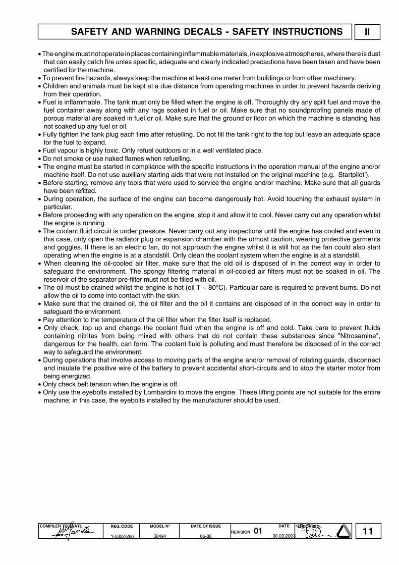
• The engine must not operate in places containing inflammable materials, in explosive atmospheres, where there is dustthat can easily catch fire unles specific, adequate and clearly indicated precautions have been taken and have beencertified for the machine.
• To prevent fire hazards, always keep the machine at least one meter from buildings or from other machinery.• Children and animals must be kept at a due distance from operating machines in order to prevent hazards deriving
from their operation.• Fuel is inflammable. The tank must only be filled when the engine is off. Thoroughly dry any spilt fuel and move the
fuel container away along with any rags soaked in fuel or oil. Make sure that no soundproofing panels made ofporous material are soaked in fuel or oil. Make sure that the ground or floor on which the machine is standing hasnot soaked up any fuel or oil.
• Fully tighten the tank plug each time after refuelling. Do not fill the tank right to the top but leave an adequate spacefor the fuel to expand.
• Fuel vapour is highly toxic. Only refuel outdoors or in a well ventilated place.• Do not smoke or use naked flames when refuelling.• The engine must be started in compliance with the specific instructions in the operation manual of the engine and/or
machine itself. Do not use auxiliary starting aids that were not installed on the original machine (e.g. Startpilot’).• Before starting, remove any tools that were used to service the engine and/or machine. Make sure that all guards
have been refitted.• During operation, the surface of the engine can become dangerously hot. Avoid touching the exhaust system in
particular.• Before proceeding with any operation on the engine, stop it and allow it to cool. Never carry out any operation whilst
the engine is running.• The coolant fluid circuit is under pressure. Never carry out any inspections until the engine has cooled and even in
this case, only open the radiator plug or expansion chamber with the utmost caution, wearing protective garmentsand goggles. If there is an electric fan, do not approach the engine whilst it is still hot as the fan could also startoperating when the engine is at a standstill. Only clean the coolant system when the engine is at a standstill.
• When cleaning the oil-cooled air filter, make sure that the old oil is disposed of in the correct way in order tosafeguard the environment. The spongy filtering material in oil-cooled air filters must not be soaked in oil. Thereservoir of the separator pre-filter must not be filled with oil.
• The oil must be drained whilst the engine is hot (oil T ~ 80°C). Particular care is required to prevent burns. Do notallow the oil to come into contact with the skin.
• Make sure that the drained oil, the oil filter and the oil it contains are disposed of in the correct way in order tosafeguard the environment.
• Pay attention to the temperature of the oil filter when the filter itself is replaced.• Only check, top up and change the coolant fluid when the engine is off and cold. Take care to prevent fluids
containing nitrites from being mixed with others that do not contain these substances since "Nitrosamine",dangerous for the health, can form. The coolant fluid is polluting and must therefore be disposed of in the correctway to safeguard the environment.
• During operations that involve access to moving parts of the engine and/or removal of rotating guards, disconnectand insulate the positive wire of the battery to prevent accidental short-circuits and to stop the starter motor frombeing energized.
• Only check belt tension when the engine is off.• Only use the eyebolts installed by Lombardini to move the engine. These lifting points are not suitable for the entire
machine; in this case, the eyebolts installed by the manufacturer should be used.
SAFETY AND WARNING DECALS - SAFETY INSTRUCTIONS

12COMPILER TECO/ATL REG. CODE
1-5302-286
MODEL N°
50494
DATE OF ISSUE
06-88REVISION 01
ENDORSEDDATE
30.03.2003
III
Codice clienteCode clientCustomer code (‘K’ No.)KundennummerCódigo cliente
Tipo motoreType moteurEngine typeMotortypeTipo motor
Matricola identificazione motoreMatricule d’identification moteurSerial numberMotornummerMatricula identificación motor
MODEL NUMBER AND IDENTIFICATION

13COMPILER TECO/ATL REG. CODE
1-5302-286
MODEL N°
50494
DATE OF ISSUE
06-88REVISION 01
ENDORSEDDATE
30.03.2003
IV
N°
mm
mm
Cm³
Kgm
Kgm
g/h
l.
Kg/h
l.
kg.
l./1'
l./1'
Kg.
ααααααααααααααα
9 LD
561-2
2
90
88
1120
17.5:1
3000
19.0/25.8
16.9/23.0
15.4/21.0
6.55
@ 2200
3.0
198
10
0.050
3.0
110
1440
24000
300
35°
25°
***
9 LD
561-2/L
2
90
88
1120
17.5:1
2200
-----
13.30/18.0
12.00/16.3
6.0
@ 2000
3.0
179
10
0.050
3.0
110
1056 **
17600**
300
35°
25°
***
9 LD
625-2
2
95
88
1248
17.5:1
3000
21/28.5
19.2/26.0
17.7/24.0
7.5
@ 2200
3.0
186
10
0.058
3.0
110
1500
26300
300
35°
25°
***
Number of cylinders
Bore
Stroke
Displacement
Compression ratio
R.P.M.
N DIN 70020
Power KW/CV NB DIN 6270
NA DIN 6270
Max. torque *
Max. torque at 3rd p.t.o.
Specific fuel consumption*
Tank capacity
Oil consumption ***
Oil sump capacity
Dry weight
Combustion air volume at 3000 r.p.m.
Cooling air volume at 3000 r.p.m.
Max. permissible driving shaft axial load in both directions
momentary
Max. inclination lasting up to 1 h.
permanent
* Referred to max. NB power** At 2200 r.p.m.*** Depending on the application
Note: For engines type 9LD560-2, currently out of production, follow the same repair instructions listed above.
ENGINE TYPE
CHARACTERISTICS 9 LD 561-2 / 9 ld 561-2/L / 9 LD 625-2
TECHNICAL DATA

14COMPILER TECO/ATL REG. CODE
1-5302-286
MODEL N°
50494
DATE OF ISSUE
06-88REVISION 01
ENDORSEDDATE
30.03.2003
NOTE

15COMPILER TECO/ATL REG. CODE
1-5302-286
MODEL N°
50494
DATE OF ISSUE
06-88REVISION 01
ENDORSEDDATE
30.03.2003
V
N (DIN 70020)Automotive rating, intermittent operation with variable speed and variable load.NB (DIN 6270)Rating with no overload capability, continuous light duty operation with constant speed and variable load.NA (DIN 6270)Continuous rating with overload capability, continuous heavy duty with constant speed and constant load..
C (NB) : Specific fuel consumption at NB powerMt : Torque at N (at NB power for 9LD561-2/L).a : Range of application for continuous operation. In case of application outside this range please contact LOMBARDINI.
The above power values refer to an engine fitted with air cleaner and standard muffler, after testing and at the environmental conditionsof 20°C and 1 bar.Max. power tolerance is 5%.Power decreases by approximately 1% every 100 m di altitude and by 2% every 5°C above 25°C.
Note: Consult LOMBARDINI for power, torque curves and specific consumptions at rates differing from those given above.
CHARACTERISTIC POWER, TORQUE AND SPECIFIC CONSUMPTION CURVES
CHARACTERISTIC POWER, TORQUE AND SPECIFIC CONSUMPTION CURVES

16COMPILER TECO/ATL REG. CODE
1-5302-286
MODEL N°
50494
DATE OF ISSUE
06-88REVISION 01
ENDORSEDDATE
30.03.2003
VI
9 LD 561-2 , 9 LD 561-2/L
OVERALL DIMENSION

17COMPILER TECO/ATL REG. CODE
1-5302-286
MODEL N°
50494
DATE OF ISSUE
06-88REVISION 01
ENDORSEDDATE
30.03.2003
VI
9 LD 625-2
OVERALL DIMENSION

18COMPILER TECO/ATL REG. CODE
1-5302-286
MODEL N°
50494
DATE OF ISSUE
06-88REVISION 01
ENDORSEDDATE
30.03.2003
VII
8 100 300 2500 5000OPERATION COMPONENT
(OIL BATH) AIR CLEANER (*) FEED PUMP FILTER
HEAD AND CYLINDER FINS (*)FUEL TANKINJECTORSINTERNAL OIL FILTER
AIR CLEANER OILLEVEL CRANKCASE OIL
BATTERY FLUIDDELIVERY VALVE TIGHTNESSVALVE AND ROCKER ARM CLEARANCEINJECTOR SPRAY PATTERN
AIR CLEANER (**) (***)OIL CRANKCASE (***)OIL FILTER CARTRIDGEFUEL FILTER CARTRIDGEDRY AIR CLEANER CARTRIDGE (O)PARTIAL (****)COMPLETE
ENGINE MAINTENANCE 9 LD 561-2 / 561-2/L - 625-2
CLEANING
CHECK
REPLACEMENT
OVERHAULINSPECTION
CAPACITIES ( liters)
Standard fuel tank 10,0
(*) Under special working conditions clean daily.(**) Under extremely dusty conditions clean every 4-5 hours.(***) See reccomended oil type.(****) Includes checking cylinders, piston rings, guides, springs, grinding valve seats, scaling heads and cylinders as well
as checking injection pump and injectors.(O) When clogging indicator shows the need for replacement.
INTERVAL (HOURS)
MAINTENANCE - RECOMMENDED OIL TYPE - REFILLING
Failure to carry out the operations described in the table may lead to technical damage to the machineand/or system

19COMPILER TECO/ATL REG. CODE
1-5302-286
MODEL N°
50494
DATE OF ISSUE
06-88REVISION 01
ENDORSEDDATE
30.03.2003
-30
-25
-20
-15
-10
-5 0
+5
+10
+15
+20
+25
+30
+35
+40
+45
SAE 20W
SAE 10W
+50
SAE 30
SAE 40
SAE 10W-30
SAE 10W-40
SAE 10W-60
SAE 15W-40 base minerale
SAE 15W-40 base semi-sintetica
SAE 20W-60 base semi-sintetica
SAE 5W-30 base sintetica
VII
SAE 0W-30 base sintetica
SAE 5W-40 base sintetica
-35
-40
CCMC G- 2
CF CE CD CC CB CA SA SB SC SD SE SF SG
DIESELBENZINA - ESSENCE - PETROL
BENZIN - GASOLINA
CCMC G- 3 G- 5CCMC PD - 1 / PD - 2
CCMC D- 2D- 4CCMC D- 3D- 5
MIL - L - 2104 DMIL - L - 2104 E
MIL - L -46152 CMIL - L- 46152 D/E
MB 226.1 MB 226.5MB 227.1 MB 227.5
228.3 MB 228.1
VW 501.01VW 500.00
SHAPIG- 4
SJ
VOLVO VDS
MAN QC 13-017
VW 505.00
GRADERECOMMENDED OIL
AGIP SUPERDIESEL MULTIGRADE 15W40 specifications API CF-4/SG ACEA E2,B2 MIL-L-46152 D/E.In the countries where AGIP products are not available, use oil APISJ/CF for Diesel engines or oil corresponding to the militaryspecification MIL-L-46152 D/E.
OIL SUPPLY ( liters ) 9 LD 561-2 / 561-2/L / 625-2
filter included 3.3filter escluded 3.0
Air cleaner oil tank 0.3
ACEA SEQUENCES
A = Gasoline (Petrol)B = Light Diesel fuelsE = Heavy Diesel fuels
Required levels :
A1-96A2-96A3-96
B1-96B2-96B3-96
E1-96E2-96E3-96
The engine could be damaged if allowed to operate with insufficient oil. It is also dangerous to add too much oil as itscombustion could sharply increase the rotation speed.Use a suitable oil in order to protect the engine.The lubrication oil influences the performances and life of the engine in an incredible way.The risk of piston seizure, jammed piston rings and rapid wear of the cylinder liner, the bearings and all moving partsincreases if oil whose characteristics differ from the recommended type is used, or if the oil is not regularly changed. Allthis notably reduces engine life.Oil viscosity must suit the ambient temperature in which the engine operates.
Old oil can cause skin cancer if repeatedly left in contact with the skin and for long periods of time. If contact with the oil isinevitable, you are advised to thoroughly wash your hands with soap and water as soon as possible.Appropriate protective gloves etc should be wore during this operation.Old oil is highly polluting and must be disposed of in the correct way. Do not litter.
MAINTENANCE - RECOMMENDED OIL TYPE - REFILLING

20COMPILER TECO/ATL REG. CODE
1-5302-286
MODEL N°
50494
DATE OF ISSUE
06-88REVISION 01
ENDORSEDDATE
30.03.2003
NOTE

21COMPILER TECO/ATL REG. CODE
1-5302-286
MODEL N°
50494
DATE OF ISSUE
06-88REVISION 01
ENDORSEDDATE
30.03.2003
VIII
1
2
3
DISASSEMBLY AND REASSEMBLY
Besides disassembly and reassembly operations this chapter alsoincludes checking and setting specifications, dimensions, repair andoperating instructions. Always use original LOMBARDINI spare partsfor proper repair operations.
0il-bath air cleaner
Check gaskets and replace if necessary.Check that flange weld is free of porosity or defective spots.Carefully clean bowl and filtering element with Diesel oil and blowthrough with compressed air.Top up with engine oil to the mark. When refitting tighten nuts at 2.5Kgm.See page 18 for periodic maintenance details.
Components:
1 Bowl2 Oil level mark3 Filtering element4 Seal ring5 Internal seal ring6 Cover7 Clamp8 Prefilter
Dry air cleaner(optional for models 9LD561 and 9LD561-2/L)
1 Hand wheel2 Cover3 Cartridge4 Seal ring5 Bracket6 Clogging indicator
Note: Replace cartridge immediately when indicator shows that isclogged.
WARNINGS!During repair operations, whenusing compressed air, wear eyeprotection.
DISASSEMBLY/REASSEMBLY

22COMPILER TECO/ATL REG. CODE
1-5302-286
MODEL N°
50494
DATE OF ISSUE
06-88REVISION 01
ENDORSEDDATE
30.03.2003
5 6
4
7
VIII
Clogging indicator
Components:1 Reset button2 Transparent indicator
Note: Indicator is calibrated at 600÷650 mm. column of water.
Oil vapour separator
Fitted to engines with dry air cleaner.Screw it out of the shroud bracket, carefully wash with gasoline insideand blow out with compressed air.When refitting connect with intake manifold by means of the specialrubber hose.
Intake manifold
Check flange surface for warpage and correct if necessary. Beforerefitting check that heads are in line. Replace gaskets. Tighten nuts at2.5 Kgm.
Note: In case of low temperature starting we can supply a manifoldwith possibility of fitting a glow plug with air preheating.
DISASSEMBLY/REASSEMBLY

23COMPILER TECO/ATL REG. CODE
1-5302-286
MODEL N°
50494
DATE OF ISSUE
06-88REVISION 01
ENDORSEDDATE
30.03.2003
VIII
9
8
10
Exhaust manifold
Check that the inside is clean.To avoid flange breakage check that heads are in line before tighteningnuts. Replace gaskets.Tighten nuts at 2 Kgm.
Pulley guard - Shroud - Side plates
Components:1 Pulley guard2 Shroud3 Side plates
The pulley guard is made of sound deadening material: it reduces thenoise that both the pulley and the fan tend to amplify.Shroud and side plates are made of ANTIFON, an elastic Iayer whichabsorbs the noise caused by the plate vibrations.
Cooling fan
Carefully clean and check all blades: if any are damaged, replace thewhole fan.See page 13 for cooling air volume.
DISASSEMBLY/REASSEMBLY

24COMPILER TECO/ATL REG. CODE
1-5302-286
MODEL N°
50494
DATE OF ISSUE
06-88REVISION 01
ENDORSEDDATE
30.03.2003
VIII
17
16
18
19
Hub
Components:1 Hub2 Alternator rotor3 Fan4 Bolt
The hub holds the alternator rotor and the cooling fan.Unscrew the bolt clockwise and tighten at 16 Kgm when refitting.
Alternator
Remove stator and place it inside the rotor to prevent metal particlesfrom being attracted by the magnets.When refitting tighten rotor screws and stator bolts at 1 Kgm.See page 56-57 for alternator characteristics.
Shroud support (Gear cover plate)
Loosen screws and remove shroud support very carefully to avoid da-mage to the oil seal ring.When refitting check that gaskets A and oil seal ring B are well insidetheir housings.Tighten screws at 2.5 Kgm.
Tank
Remove fuel filter and loosen clamp screws.Completely empty the tank and check that no impurities are foundinside.Check that cap breather hole is not clogged.When refitting tighten bracket screws at 4 Kgm.See page 49 for refitting fuel filter.
DISASSEMBLY/REASSEMBLY

25COMPILER TECO/ATL REG. CODE
1-5302-286
MODEL N°
50494
DATE OF ISSUE
06-88REVISION 01
ENDORSEDDATE
30.03.2003
VIII
16 17
15
18
19 20
Flywheel
Remove flywhee] with puller 1 (part No. 7271-3595-048).Check starter ring gear and tapered crankshaft mating surfaces.When refitting tighten bolt al 30 Kgm.
Note: To replace starter ring gear heat it up lo 200÷250°C and rapidlydrive it onto the flywheel.
Valve / rocker arm clearance
Remove rocker arm cover and check gaskets for breakage.Setting should be performed when the engine is cold: bring eachcylinder piston to top dead center on the compression stroke and setclearance A al 0.15÷0.20 mm.When refitting tighten cover screws by 2 Kgm.
Compression release (optional)
Bring piston to top dead center on the compression stroke.Unscrew rocker arm cover side plug and measure clearance A. Itmust be 0.30÷0.40 mm.For setting purposes remove rocker arm cover, unscrew lock nut andset clearance A, by adding or removing shims under steeI plate (pointB).
Rocker arm assembly
Components:1 Bore2 Lubrication tube
Dimensions (mm):A = 18.032÷18.050B = 17.989÷18.000If clearance (A-B) exceeds 0. 135 mm. replace shaft and rocker arms.When retitting check that lubrication tube perfectly matches with thejournal bore.Tighten screws al 2.5 Kgm.
DISASSEMBLY/REASSEMBLY

26COMPILER TECO/ATL REG. CODE
1-5302-286
MODEL N°
50494
DATE OF ISSUE
06-88REVISION 01
ENDORSEDDATE
30.03.2003
VIII
22
21
23
Injector
Clean injector and cheek calibrated pressure as indicated on page 55.When refitting cheek that it correctly protrudes from the cylinder headplane.Tighten the fixing nuts at 1 Kgm.
Injector projection
The end of nozzle A should project 3.0÷3.5 mm. from the cylinder headplane.Adjust injector projection by means of copper shims B measuring 0.5and 1.00 mm. in thickness.
CYLINDER HEAD
Do not remove it when hot to avoid deformation. lf cylinder head isdeformed level it off by removing a maximum of 0.3 mm.When refitting tighten only if sure that rocker arm lubrication tube is wellinside its holes and that both heads are well in line.Always replace copper head gasket: see page 32 for choosing theright thickness.Progressively tighten nuts in the 1, 2, 3, 4 sequence at 5.5 Kgm.
DISASSEMBLY/REASSEMBLY

27COMPILER TECO/ATL REG. CODE
1-5302-286
MODEL N°
50494
DATE OF ISSUE
06-88REVISION 01
ENDORSEDDATE
30.03.2003
VIII
24 25
26
27 28
Valves
Components:1 Intake valve2 Spring seat3 Valve stem oil seal4 Spring5 Retainer6 Half colletsTo remove half collets firmly press down as shown in the figure.
Note: Valve stem oil seal, 3 must be fitted to the intake valve only.
Valve springs
Measure free length with a gauge.Using a dynamometer check that the spring length under two dìfferentloads corresponds to the values below:
Engine type 9LD561-2Free length A = 52 mmLength B compressed by a 21 Kg weight = 34.8 mmLength C compressed by a 32 Kg weight = 25.8 mmEngine type 9LD625-2Free length A = 47 mmLength B compressed by a 20.6 Kg weight = 36.4 mmLength C compressed by a 40.6 Kg weight = 26.1 mmReplace spring if length is 1 mm or more below the stated values.
Valve material
Intake valves AMaterial: X 45 Cr Si 8 UNI 39921 Chromium-plated portiona 45°15'÷45°25'
Exhaust valve BShaft and head are made of 2 different materials.2 Welded portion3 Chromium-plated portion4 Portion made of X 45 Cr Si 8 UNI 39925 Portion made of X 70 Cr Mn Ni N 216 UNI 3992a 45°15'÷45°25'
DISASSEMBLY/REASSEMBLY

28COMPILER TECO/ATL REG. CODE
1-5302-286
MODEL N°
50494
DATE OF ISSUE
06-88REVISION 01
ENDORSEDDATE
30.03.2003
VIII
30
29
31
Valve guides and valve guide housings
Starting from engine No. 2883619 intake and exhaust valve guidesare both made of phosphoric cast iron.Components:1 = Exhaust valve guide2 = Intake valve guideDimensions (mm):A = 42,0B ={48,5 (for 9LD561-2 and 9LD561-2/L)
53,5 (for 9LD625-2)C = 14,000÷14,018D = 14,050÷14,060Valve guides with outside diameter increased by 0.5 mm. are alsoavailable;in such cases valve guide bore C shouid also be increasedby 0.5 mm.
Valve guide insertion
Heat cylinder head up to 160÷180°CPress guides considering the A and B distances from the head plane.Dimensions (mm):A = 30.80÷31.20B = 24.80÷25.20 (for 9LD561-2 and 9LD561-2/L)C = 20.3÷20.7 (for 9LD625-2)
Note: lf guides are seated with stop ring C, first locate the ring in placeand then position guides without considering A and B.
Dimensions and clearance between guides and valves (mm)
A = 8.030÷8.045B = 7.985÷8.000(A-B) = 0.030÷0.060(A-B)limit value = 0.15
DISASSEMBLY/REASSEMBLY
29COMPILER TECO/ATL REG. CODE
1-5302-286
MODEL N°
50494
DATE OF ISSUE
06-88REVISION 01
ENDORSEDDATE
30.03.2003
VIII
33 34
32
35
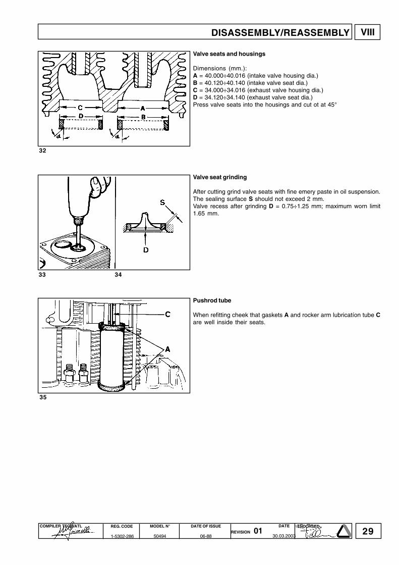
Valve seats and housings
Dimensions (mm.):A = 40.000÷40.016 (intake valve housing dia.)B = 40.120÷40.140 (intake valve seat dia.)C = 34.000÷34.016 (exhaust valve housing dia.)D = 34.120÷34.140 (exhaust valve seat dia.)Press valve seats into the housings and cut ot at 45°
Valve seat grinding
After cutting grind valve seats with fine emery paste in oil suspension.The sealing surface S should not exceed 2 mm.Valve recess after grinding D = 0.75÷1.25 mm; maximum worn limit1.65 mm.
Pushrod tube
When refitting cheek that gaskets A and rocker arm lubricatíon tube Care well inside their seats.
DISASSEMBLY/REASSEMBLY

30COMPILER TECO/ATL REG. CODE
1-5302-286
MODEL N°
50494
DATE OF ISSUE
06-88REVISION 01
ENDORSEDDATE
30.03.2003
VIII
38
36 37
39 40
CYLINDER
Measure diameter size between two diametrically opposed points atthree different heights.For 9LD561-2 and 9LD561-2/L Ø = 90.00 ÷ 90.02 mmFor 9LD625-2 Ø = 95.00 ÷ 95.02 mm.In case wear exceeds 0.10 mm, bore the cylinder and fit oversizepiston and rings.In case of less wear replace piston rings only.
Checks and cylinder roughness
The cylinder should show no blowholes or porosities.Seal both ends of cylinder and pressurize with compressed air at 4Bar for 30 secs. Immerse in water and check for leakage.Fins must be intact.Cross hatch pattern must range between 115°÷140°: they must beuniform and clear in both directions.Average roughness should range between 0.5 and 1 µ.
PISTON
Remove circlips and remove piston pin.Remove piston rings and clean grooves.Measure diameter at 2 mm from the bottom of skirt.For 9LD561-2 and 9LD561-2/L Ø = 89.90 ÷ 89.92 mmFor 9LD625-2 Ø = 94.93 ÷ 94.95 mmIn case of diameter wear above 0.05 mm replace piston and pistonrings.
Note: Oversize pistons of 0.5 and 1 .0 mm are available.
DISASSEMBLY/REASSEMBLY

31COMPILER TECO/ATL REG. CODE
1-5302-286
MODEL N°
50494
DATE OF ISSUE
06-88REVISION 01
ENDORSEDDATE
30.03.2003
VIII
42
41
43 44
45
Piston weight
Weigh pistons when replacing them in order to avoid unbalance. Thedifference in weight should not exceed 6 g.
Piston rings - End gaps (mm)
Place piston rings squarely into the unworn part of the lower cylinderand measure the end gap.
For 9LD561-2 and 9LD561-2/L1° Chromium-plated ring A = 0.40÷0.652° Torsional (internal tapered) ring A = 0.40÷0.653° Oil control ring A = 0.25÷0.40
For 9LD625-21° Chromium-plated ring A = 0.40÷0.652° Torsional (internal tapered) ring A = 0.40÷0.653° Oil control ring A = 0.30÷0.60
Pistons ringis - Clearance between grooves (mm)
For 9LD561-2 and 9LD561-2/LA = 0.11÷0.15; limit value = 0.25B = 0.06÷0.10; limit value = 0.18C = 0.05÷0.10; limit value = 0.18
For 9LD625-2A = 0.07÷0.11; limit value = 0.20B = 0.05÷0.09; limit value = 0.16C = 0.04÷0.08; limit value = 0.15
Piston rings - Fitting sequence
A = 1° Chromium-plated ringB = 2° Torsional (internal tapered) ringC = 3° oil control ring
Note: Before fitting the piston into the cylinder stagger the ring gaps at120°.
DISASSEMBLY/REASSEMBLY

32COMPILER TECO/ATL REG. CODE
1-5302-286
MODEL N°
50494
DATE OF ISSUE
06-88REVISION 01
ENDORSEDDATE
30.03.2003
VIII
48 49
46 47
50 51
52
Piston - Refitting
Connect piston to connecting rod in a way that the combustion chambercentre b is at right angle under nozzle tip a.Lubricate piston pin and introduce it into the piston by exerting pressurewith your thumb.Check that both circlips are well inside their seats.
Piston clearance
A = Piston clearanceB = Copper head gasket
A (0.65÷0.7 mm) is determined by placing the piston at top dead centerand measuring with a feeler gauge and straight edge, the distance thepiston is below or above the cylinder face. A copper gasket (availablein various thicknesses) is them selected to ensure the clearance iscorrect.Gaskets are available in the following thicknesses 0.45, 0.5, 0.55, 0.6,0.65, 0.7, 0.75, 0.8, 0.85, 0.9, 0.95, 1.00 mm.
CONNECTING ROD
Remove oil pan.Remove connecting rods and check as follows.Both connecting rod/piston units should be fitted back into thecorresponding cylinders; mark them to avoid mistakes.See page 33 for specifications as to the tightening of the connectingrod big end bearing.
Connecting rod small end bushing
Dimensions and clearance (mm):C = 25.020÷25.030 (with machined bushing in place)D = 24.995÷25.000(C-D) = 0.020÷0.035(C-D) maximum worn limit = 0.070
DISASSEMBLY/REASSEMBLY

33COMPILER TECO/ATL REG. CODE
1-5302-286
MODEL N°
50494
DATE OF ISSUE
06-88REVISION 01
ENDORSEDDATE
30.03.2003
VIII
54
53
55 56
Connecting rod alignment
Check alignment of small end and big end bearing bores using fittedmandrels; axial mis-alignment A = 0.02 mm; maximum limit = 0.05mm Moderate warpage may be corrected by gradually working with apress.
Connecting rod weight
Weigh connecting rods when replacing them in order to avoidunbalance.The difference in weight should not exceed 10 g.
Connecting rod big end bearing
Both centering notches A and B must be on the same side whenrefitting. Tighten bolts at 4 Kgm.See page 32 for dimensions.
DISASSEMBLY/REASSEMBLY

34COMPILER TECO/ATL REG. CODE
1-5302-286
MODEL N°
50494
DATE OF ISSUE
06-88REVISION 01
ENDORSEDDATE
30.03.2003
VIII
58
57
59
Crankshaft timing gear
Use tool 1 (Part No. 7560-4000-052) and puller 2 (Part No. 7271-3595-048) to remove the gear.
Main bearing support, gear side
Remove main bearing by means of two M8x1.25 screws with fullythreaded length of 40 mm or a puller (Part No. 7271-3595-048).
Note: To avoid deformation it is not recomended to replace the bearingbushing, complete assembly's of bushing and support are availablein standard, 0.25 mm and 0.50 mm undersize configurations as spareparts.See page 32 for dimensions.
Main bearing support, flywheeI side
Remove it by means of two M8x1.25 screws with fully threaded lengthof 40 mm.Check oil seal ring and replace if warped, hardened or worn-out. Whenrefitting, tighten nuts at 2.5 Kgm.See end float on page 31 for gasket replacement detaiis.See page 31 for dimensions.
DISASSEMBLY/REASSEMBLY

35COMPILER TECO/ATL REG. CODE
1-5302-286
MODEL N°
50494
DATE OF ISSUE
06-88REVISION 01
ENDORSEDDATE
30.03.2003
VIII
61
60
62
CRANKSHAFT
Center main bearing support, locating bolt.Straighten plate 1 and unscrew bolt 2 before removing crankshaft.
Crankshaft removal
To pull out the crankshaft tap lightfy on the timing side end using acopper-headed hammer.When refitting align center main bearing support so that the locatingbolt hole coincides with the crankcase hole.
Crankshaft center main bearing support
When refitting, both centering notches A and B must be located on thesame side.Tighten screws at 2.5 Kgm.See page 31 for dimensions.
DISASSEMBLY/REASSEMBLY

36COMPILER TECO/ATL REG. CODE
1-5302-286
MODEL N°
50494
DATE OF ISSUE
06-88REVISION 01
ENDORSEDDATE
30.03.2003
VIII
63 64
65
66
67
Crankshaft lubrication ducts
Remove plugs, clean duct A with a pointed tool and blow in compressedair.Screw plugs again and check for sealing.
Crankshaft journal radiusThe radius R connecting journals to shoulders is 2.8÷3.2 mm.
Note: When grinding main journals or crank pins restore the R value tooriginal specification.
Checking main journals and crank pins
Use an outside micrometer gauge.
Main journal and crank pin diameter (mm)
A = 71.981÷72.000B = 45.500÷45.516C = 55.331÷55.350D = 54.931÷54.950
DISASSEMBLY/REASSEMBLY

37COMPILER TECO/ATL REG. CODE
1-5302-286
MODEL N°
50494
DATE OF ISSUE
06-88REVISION 01
ENDORSEDDATE
30.03.2003
VIII
68
69
70
How to measure main bearing inside diameter
Use an inside micrometer gauge.
Main bearing and connecting rod big end bearing inside diameter
Dimensions (mm):E = 72.070÷72.090F = 45.548÷45.578G = 55.404÷55.435H = 55.000÷55.020The above dimensions refer to driven in or tightened bearings.
Note: Both main bearings and connecting rod big end bearings areavailable with inside diameter size measuring 0.25 and 0.50 mm lessthan the standard version.
Clearance between main journals/crank pins and connecting rodbearings (mm)
(E-A) = 0.070÷0.109; limit value = 0.195(F-B) = 0.032÷0.078; limit value = 0.150(G-C) = 0.054÷0.104;limit value = 0.190(H-D) = 0,050÷0.089;limit value = 0.180
DISASSEMBLY/REASSEMBLY

38COMPILER TECO/ATL REG. CODE
1-5302-286
MODEL N°
50494
DATE OF ISSUE
06-88REVISION 01
ENDORSEDDATE
30.03.2003
VIII
71
72
73
Main bearíng supports
1 Flywheel side2 Central3 Gear side
Dimensions (mm):I = 149. 000÷149.020L = 76.980÷77.020M =147. 010÷147.020N = 59.074÷59.0920 = 75.990÷76.010P =60.000÷60.020
Main bearing housings
Dimensions (mm):A = 149.000÷149.020B = 147.000÷147.020C = 76.000÷76.020
Crankshaft end play
When refitting crankshaft check end play by means of a thicknessgauge; this value should be 0.08÷ 0.38 mm and can be set by changingthe thickness of gasket A which is located on the flywheel-side mainbearings.Gaskets with thickness of 0.10, 0.20 and 0.4 mm can be supplied.
DISASSEMBLY/REASSEMBLY

39COMPILER TECO/ATL REG. CODE
1-5302-286
MODEL N°
50494
DATE OF ISSUE
06-88REVISION 01
ENDORSEDDATE
30.03.2003
76
74 75
77 78
VIII
CAMSHAFT
How to measure camshaft journals and housingsUse an inside micrometer gauge for housings and an outsidemicrometer gauge for journals.
Dimensions of camshaft journals and housings (mm)
A = 41.940÷41.960B = 27.940÷27.960C = 42.000÷42.025D = 28.000÷28.020
Clearance (mm)(C-A) = 0.040÷0.085;(C-A) limit value = 0.160(D-B) = 0.040÷0.080;(D-B) limit value = 0.150
How to measure intake/exhaust cam height
A1 = 1 st cylinder intake camS1 = 1 st cylinder exhaust camA2 = 2nd cylinder intake camS2 = 2nd cylinder exhaust camExhaust and intake cams feature the same height H.For 9LD561-2 and 9LD561-21L, H = 33.95÷34-05 mmFor 9LD625-2, H = 33.55÷33.65 mmReplace camshaft if H is 0.1 mm below the given value.
DISASSEMBLY/REASSEMBLY

40COMPILER TECO/ATL REG. CODE
1-5302-286
MODEL N°
50494
DATE OF ISSUE
06-88REVISION 01
ENDORSEDDATE
30.03.2003
79
VIII
80
81
Camshaft end play
End play should be 0.10÷0.26 mm; check by means of a dial gaugepushing or pulling camshaft as required.
Camshaft timing
Fit camshaft gear by making timing mark 1 coincide with timing -mark2 on the crankshaft timing gear.Tighten camshaft boll at 6 Kgm.
Valve timing without considering timing marks
Locate piston 1 (on flywheel side) at the top dead centre.Position two small cylinders A of the same height onto the tappets.Rotate camshaft stopping when cylinder 1 tappets are in overlapposition (intake open, exhaust closed).By means of ruler B check that tappets are at the same height.Engage camshaft gear with crankshaft gear.
DISASSEMBLY/REASSEMBLY

41COMPILER TECO/ATL REG. CODE
1-5302-286
MODEL N°
50494
DATE OF ISSUE
06-88REVISION 01
ENDORSEDDATE
30.03.2003
82
VIII
83
9LD561-2 α α α α α = 2°β β β β β = 34°γ γ γ γ γ = 34°δ δ δ δ δ = 2°
9LD625-2 α α α α α = 1°β β β β β = 21°γ γ γ γ γ = 23°δ δ δ δ δ = 1°
Valve timing check
Check valve timing at the crankshaft.The values shown are checked at the flywheel circumference (withflywheel of 291 mm. diameter each degree corresponds to 2.5 mm).Set valve clearance at 0.65÷0.70 mm (after checking restore the valueat 0. 15÷0.20 mm). Set dial gauge on intake valve to a zero value; byrotating the driving shaft according to its direction of rotation you canmeasure a (intake valve opening advance referred to top dead centreS) and ß (intake valve closing delay referred to bottom (I) dead centre).Follow the same procedure for exhaust valves checking y (exhaustvalve opening advance) and 6 (exhaust valve closing delay): in thecase of 9LD625-2 6 is advanced by 1° compared to S.
DISASSEMBLY/REASSEMBLY

42COMPILER TECO/ATL REG. CODE
1-5302-286
MODEL N°
50494
DATE OF ISSUE
06-88REVISION 01
ENDORSEDDATE
30.03.2003
VIII
84
85
86
87
Hydraulic pump p.t.o.
A hydraulic pump of group 1 (1 P) or 2 (2P) can be installed on the gearside, 3rd p.t.o.
Hydraulic pump p.t.o. (1 P)
Components: 1 Seal ring 2 Centering ring 3 Coupling 4 Half coupling 5 Flange 6 Gear 7 Bracket 8 Thrust washer 9 Stop ring10 CoverThe maximum total torque is thus 3 Kgm corresponding to 12.5 HP at3000 r.p.m. Reduction ratio 1:1
MECHANICAL SPEED GOVERNOR
Weight-type governor housed inside the camshaft drive gear.
Mechanical speed governor
Components:1 Gear 2 Weight3 Mobile bell 4 Stop ring5 Thrust washer 6 Yoke7 Lever 8 Drive rod9 Governor spring 10 Rack control lever
Weights are moved to the periphery by the centrifugal force and thusaxially shift a mobile bell connected to the injection pump rack controllever by a linkage. A spring placed under tension by the acceleratorcontrol offset the weight centrifugal force. Balance between the twoforces keeps speed at an almost constant level in spite of loadvariations. See page 44 for timing.
DISASSEMBLY/REASSEMBLY

43COMPILER TECO/ATL REG. CODE
1-5302-286
MODEL N°
50494
DATE OF ISSUE
06-88REVISION 01
ENDORSEDDATE
30.03.2003
89
88
90
VIII
Governor springs with rocker arm
The system features two springs anchored to a rocker arm and allowsfor minimal r.p.m. changes at low speed levels.
Governor springs with rocker arm
Components:1 Rocker arm for spring anchoring2 Governor springs3 Plate4 Link5 Lever
Spring for extra fuel supply at starting
Components:1 Extra fuel spring2 lnjection pump control yoke3 Governor spring.
The device is operated automatically: when the engine is stoppedspring 1 acts on injection pump control yoke 2 providing maximumfuel delivery, until the engine starts and the governor controls the iniectionpump rack.
DISASSEMBLY/REASSEMBLY

44COMPILER TECO/ATL REG. CODE
1-5302-286
MODEL N°
50494
DATE OF ISSUE
06-88REVISION 01
ENDORSEDDATE
30.03.2003
91
VIII
92
93
ELECTRONIC SPEED GOVERNOR(optional)
A = ActuatorS = r.p.m. sensor
An electronic speed governor can be fitted upon request to engineswith serial number greater than 2907859. The crankcase features ahole for sensor S introduction.
Electronic speed governor
Components:1 Injection pump2 Delivery control lever3 Actuator A mounting flange4 Mobile retainer5 Actuator magnet6 Stator coils7 Stator8 Cable ends for connection to control box E9 Electromagnet
Electronic speed governor layout
Components: A = actuator; C = key; P = potentiometer; T=electromagnet; S = sensorThe device consists of an actuator A controlling injection pump rack,an r.p.m. sensor S and an electromagnet T controlling fuel deliveryand supplying extra fuel at starting. Control box E (see page 35)controls fuel delivery as a function of the load and of the speed setthrough potentiometer P.The potentiometer can be fìtted on the control box or on the controlpanel P1 (see page 35).The whole system makes it possible to keep the engine speedconstant independently of the load conditions. It detects speed throughthe r.p.m. sensor mounted on the crankcase at the ring gear level. Asthe number of revolutions changes the device immediately performsthe required corrections by means of the actuator acting on the injectionpump. Electromagnet T responds to max. fuel delivery (fuel flow setting)and (when energized) enables the injection pump rack rod to reach itsmaximum stroke (extra fuel supplied at starting).
DISASSEMBLY/REASSEMBLY

45COMPILER TECO/ATL REG. CODE
1-5302-286
MODEL N°
50494
DATE OF ISSUE
06-88REVISION 01
ENDORSEDDATE
30.03.2003
VIII
94
95
96
Starting with electronic speed governor(see lay-out on page 44)
In position O the engine is not working and no part is energized. Therack rod is in stop position (retained by two springs 10 inside actuatorA). By rotating key C to position 2 the electromagnet with drawsallowing the rack rod to reach its highest delivery being connected tothe actuator at its max. level of energization. When the engine,immediately after starting, reaches 1000 r.p.m. the controller reducesthe actuator position, after 1 second swìtches off the electromagnet Tand after more 0.5 seconds returns at his normal position with theengine speed set as per position of potentiometer P1.
Engine running with electronic speed governor
The engine starts running at the pre-set speed.Potentiometer P is located either inside the control box E or on controlpanel P1.In case of an external potentiometer P1 the engine speed can be set atany point between the idling and full speed in on-load conditions(setting performed on the control box in the test room).The electronic control box E controls actuator A (by sending or cuttingoff the power supply) to keep the speed set through P1 constantindependently of the absorbed load.Control box E prevents the engine from starting (or stops it) in case ofno power supply or in case connection with r.p.m. sensor S is broken(or short-circuited).
Electronic speed governor control box
Control box E features four setscrews which must be positioned onthe test bed (torque dynamometer) along with the engine.a) Setscrew for speed control (r.p.m.)b) Setscrew for sensitivity adjustment when the engine is runningat full speed.c) Setscrew for sensitivity adjustment at low speed.d) Setscrew for extra fuel release; once correctly positioned, thisset-screw is generally sealed.
DISASSEMBLY/REASSEMBLY

46COMPILER TECO/ATL REG. CODE
1-5302-286
MODEL N°
50494
DATE OF ISSUE
06-88REVISION 01
ENDORSEDDATE
30.03.2003
97
IX
Components:
1) Oil pressure switch - 2) Breather - 3) Connecting rod big end bearing - 4) Crankshaft main bearing on gear side - 5) Oílpressure relief valve - 6) Fitting tor pressure gauge connecl:Ion - 7) Cartridge filter , 8) Oil pump - 9) Oil fill plug - 10)Rocker arm shafts 11) Pushrod protection tube - 12) Hydraulic pump gear - 13) Camshaft joumal on fiywheel side - 1,~)Oìl dipstick - 15) Drain plug . 16) Internal filter
LUBRICATION SYSTEM
LUBRICATION SYSTEM AND BREATHER RECIRCULATION SYSTEM
The engine can be damaged if allowed to operate with insufficient oil. It is also dangerous to add too much oil becauseits combustion may lead to a sharp increase in the rotation speed.Use suitable oil in order to protect the engine.Nothing more than lubrication oil can influence the performances and life of an engine.Use of an inferior quality oil or failure to regularly change the oil will increase the risk of piston seizure, will cause thepiston rings to jam and will lead to rapid wear on the cylinder liner, the bearings and all other moving parts. Engine life willalso be notably reduced.The oil viscosity must suit the ambient temperature in which the engine operates.
Old engine oil can cause skin cancer if repeatedly left in contact with the skin and for long periods of time. Wear protectivegloves to avoid touching used oil. If contact with the oil is unavoidable, you are advised to wash your hands with soap andwater as soon as possible. Dispose of old oil in the correct way as it is highly polluting.

47COMPILER TECO/ATL REG. CODE
1-5302-286
MODEL N°
50494
DATE OF ISSUE
06-88REVISION 01
ENDORSEDDATE
30.03.2003
IX
98 99
100
101 102
103
OIL PUMP
Check that gear teeth are intact and that clearance between gear edgeand pump body does not exceed 0.15 mm.Further more check that control shaft is free to rotate with end float notexceeding 0.15 mm.Oil pump delivery al 3000 r.p.m. is 9 liters/min.
Oil filter cartridge (internal)
Components:1 Plug2 Seal ring3 Spring4 CartridgeFeatures:Type of filtration: 70 µBy-pass valve opening pressure: 0.60÷0.75 bar.Max. working pressure: 4.5 bar.
Oil pressure relief valve
Components:1 Plug2 Gasket3 Spring4 ValveA = 37 mmCarefully clean all components and check spring A length.
Oil pressure check
Once the engine is fitted fill with oil and fuel; connect a 10 bar pressuregauge to the oil filter fitting.Start the engine and check pressure as a function of the oil temperature(see page 48)
LUBRICATION SYSTEM

48COMPILER TECO/ATL REG. CODE
1-5302-286
MODEL N°
50494
DATE OF ISSUE
06-88REVISION 01
ENDORSEDDATE
30.03.2003
IX
105
104
Oil pressure curve at idling speed
The curve is obtained at the oil filter lever with constant engine speedof 1200 r.p.m. in no-load conditions and at a room temperature of +25°C.Pressure is given in bar and temperature in centigrades.
Oil pressure curve at full speed
The curve is obtained at the oil filter level with engine working at 3000r.p.m. and 25.84 HP at + 25°C room temperature.Pressure is given in bar and temperature in centigrades.
LUBRICATION SYSTEM

49COMPILER TECO/ATL REG. CODE
1-5302-286
MODEL N°
50494
DATE OF ISSUE
06-88REVISION 01
ENDORSEDDATE
30.03.2003
X
106
107
108
109
Fuel feeding/injection circuit
Components:1 Tank2 Filter3 Fuel feeding tube4 Fuel feeding pump5 lnjection pump6 Injection line7 Injector8 Injector leak off line and self bleeding system
Fuel filter (inside fuel tank)
Components:1 Spring2 Disc3 Ring4 Cartridge5 Gasket6 Gasket7 Cap8 Ring9 Bolt
Fuel feeding pump
The fuel feeding pump is of the diaphgragm type operated by acamshaft eccentric through a drive rod. It features an external lever formanual operation.Characteristics: when the control eccentric rotates at 1500 r.p.m.rninimum delivery is 64 l/h while self-regulation pressure is 4÷5 mwater column.
Fuel feeding pump drive rod protrusion
Components:1 Drive rod2 Gasket3 Camshaft eccentricDrive rod A protrudes 0.8-1.2 mm from the crankcase; it can be adjustedby means of gaskets.Gaskets are supplied in the following thicknesses: 0.50, 0.80 and 1.0mm.
Note: This setting is performed when the rod is on the base of the camlobe (i.e. minimum protrusion).
FUEL SYSTEM

50COMPILER TECO/ATL REG. CODE
1-5302-286
MODEL N°
50494
DATE OF ISSUE
06-88REVISION 01
ENDORSEDDATE
30.03.2003
110
111
112
X
INJECTION PUMP
The Bosch injection system consists of a single-body pump withplungers featuring constant stroke and feeding one cylinder each. Thepump, mounted on the crankcase is directly operated by the camshaft.Speed governor, extra fuel and stop device are separate from the pump(see page 42, 43 and 66).
Injection pump
Components: 1 Pump body 2 Fitting 3 Seal ring 4 Filter 5 Shim 6 Spring 7 Delivery valve 8 Seat 9 Gasket 10 Plunger11 Barrel 12 Rack rod13 Sector gear 14 Spring15 Upper retainer 16 Lower retainer17 Tappet 18 Tappet roller
Plunger and Barrel Assembly
1 Barrel2 Fuel feeding port3 Control helix4 Plunger5 Retardation notch (only for 9LD625-2)Plunger diameter is 7 mm for 9LD561-2 and 9LD561-2/L and 7.5 mm for 9LD625-2.
Note: Every plunger matches with its own barrel. For this reason theyare not interchangeable.
FUEL SYSTEM

51COMPILER TECO/ATL REG. CODE
1-5302-286
MODEL N°
50494
DATE OF ISSUE
06-88REVISION 01
ENDORSEDDATE
30.03.2003
113
X
114 115
116
How to check plunger and barrel for internal leakage
This operation is only indicative since pressure changes dependingon the pumping speed.Connect the delivery union with a 600 bar pressure gauge with safetyvalve. Adjust rack rod at half-stroke. Turn flywheel according to itsdirection of rotation so that the plunger puts the circuit under pressure.Replace plunger if the displayed pressure is below 300 bar. Repeatthe same operation for the other plunger.
How to check injection pump delivery valve sealing
Components:1 Valves2 SeatAdjust pump rack at half-stroke. Turn flywheel according to its directionof rotation so that the plunger puts the circuit under pressure.During this operation the displayed pressure will gradually reach apeak followed by a sudden drop which corresponds to valve closing.Pressure drop should be 30÷50 bar. Replace the valve if pressuredrop is below this value.Repeat the same operation for the other plunger.
Test data for injection pump delivery
For 9LD561-2 and 9LD561-2/L
Check only maximum plunger difference by positioning rack rodaccording to the indicated delivery value.
For 9LD625-2
FUEL SYSTEM
Control rodmax. force
Rod strokefrom maxdeliv. point
R.P.M. dELIVERYMax. plunger
difference
Newton mm mm3/stroke mm3/stroke
0,50
10 1500 27÷37 4
0 150 75÷90 -------
---- * 500 10 4
Control rodmax. force
Rod strokefrom maxdeliv. point
R.P.M. DeliveryMax. plunger
difference
Newton mm mm3/stroke mm3/stroke
0,50
10 1500 34÷37 3
13 500 7÷11 3
0 150 70÷78 --------
10 500 22÷26 3

52COMPILER TECO/ATL REG. CODE
1-5302-286
MODEL N°
50494
DATE OF ISSUE
06-88REVISION 01
ENDORSEDDATE
30.03.2003
X
117
118
119
How to reassemble injection pump components
After replacing the worn-out components, reassemble the pump asfollows:Introduce sector gears into the pump body by making reference pointsC match with the B points on the rack.Fix barrels with the eccentric screws F on the pump body.Fit valves with seats, springs, fillers and delivery unions tighteningthem at 3.5÷4 Kgm.Fit plungers by making reference points E match with the sector gearD points.Fix retainers and springs; lock tappet with special stop.Check that both plungers have the same delivery by performing thenecessary measurements at the test bed; if delivery is not the sameset screw F.
How to mount injection pump on the engine
Tighten screws at 2.5 KgmCheck that rack rod slides smoothly: if not, the engine may fail to startor hunt.
Injection pump/mechanical speed governor timing
Loosen screw 1Move injection pump lever 2 to maximum delivery (to the right).Check that drive rod 3 closes the speed governor; keeping lever 2pressed to the right the drive rod should have no clearance.Tighten screw 1.
FUEL SYSTEM
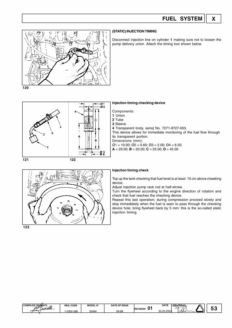
53COMPILER TECO/ATL REG. CODE
1-5302-286
MODEL N°
50494
DATE OF ISSUE
06-88REVISION 01
ENDORSEDDATE
30.03.2003
X
120
121 122
123
(STATIC) INJECTION TIMING
Disconnect injection line on cylinder 1 making sure not to loosen thepump delivery union. Attach the timing tool shown below.
Injection timing checking device
Components:1 Union2 Tube3 Sleeve4 Transparent body, seria] No. 7271-9727-003.This device allows for immediate monitoring of the fuel flow throughits transparent portion.Dimensìons (mm):Ø1 = 10.00; Ø2 = 0.60; Ø3 = 2.00; Ø4 = 6.50.A = 29.00; B = 20.00; C = 25.00; D = 45.00
Injection timing check
Top up the tank checking that fuel level is at least 10 cm above cheekingdevice.Adjust injection pump rack rod at half-stroke.Turn the flywheel according to the engine direction of rotation andcheck that fuel reaches the checking device.Repeat this last operation; during compression proceed slowly andstop immediately when the fuel is seen to pass through the checkingdevice hole; bring flywheel back by 5 mm: this is the so-called staticinjection timing.
FUEL SYSTEM

54COMPILER TECO/ATL REG. CODE
1-5302-286
MODEL N°
50494
DATE OF ISSUE
06-88REVISION 01
ENDORSEDDATE
30.03.2003
X
124
125
126 127
Injection timing reference marks on crankcase and flywheeI
A = Piston reference mark at the top dead centreB = Injection timing reference mark compared to AA ÷ B = Distance in mm.C = Piston reference mark in injection timing position.a = Reference angle in degrees.
Engine type (A-B) mm ci9LD561-2 61÷ 66 24°÷ 26°9LD561-2/L 56÷61 22°÷24°9LD625-2 63,5 ÷68,5 25°÷ 27°
Check window for injection timing reference mark
Components:1) Window2) Injection timing reference markA window is provided to identify the reference mark corresponding tothe above mark C.
Injection timing correction
lf reference mark C does not match with B follow examples 1 and 2.1) Example of late injection timing: remove shims under the pump tomake C match with B.2) Example of early injection timing add shim under the pump to makeC match with B.
Note: By adding or removing a 0.1 mm shim under the pump C isdelayed or advanced by approximately 3 mm.
FUEL SYSTEM

55COMPILER TECO/ATL REG. CODE
1-5302-286
MODEL N°
50494
DATE OF ISSUE
06-88REVISION 01
ENDORSEDDATE
30.03.2003
128
129
130
X
INJECTOR
Components: 1 Intake fitting 2 Nozzle holder 3 Shim 4 Spring 5 Pressure rod 6 Intermediate flange 7 Nozzle 8 Needle valve 9 Fixing flange10 Taper pin11 Gasket12 System duct13 Sump
Nozzle
Features:Hole number and diameter 4x0.28 mm.Jet angles = 160°.Needle valve elevation = 0.20 ÷ 0.22 mmHole length = 0.7 mmSump diameter and length = 1x1.5 mm
Injector setting
Conect injector to a hand pump and cheek that setting pressure is 210÷220 bar; make the required adjustments, if any, by changing the shimover the spring.When replacing the spring, setting should be performed at a 10 bargreater pressure (220÷230 bar) to allow for bedding during operation.Check needle valve sealing by slowly moving hand pump untilapproximately 180 bar.Replace nozzle in case of dripping.
FUEL SYSTEM

56COMPILER TECO/ATL REG. CODE
1-5302-286
MODEL N°
50494
DATE OF ISSUE
06-88REVISION 01
ENDORSEDDATE
30.03.2003
131
XI
132
133
STANDARD ELECTRIC EQUIPMENT
Electric starting layout without battery charging lightComponents:1 Alternator2 Starting motor3 Voltage regulator4 Battery5 Pressure switch6 Oil pressure warning light7 Key switch
Electrical starting layout with battery charging light
Components:1 Alternator2 Starting motor3 Voltage regulator4 Battery5 Pressure switch6 Oil pressure warning light7 Key switch8 Battery charging light
Note: Battery, which is not supplied by Lombardini, should feature 12V voltage and capacity not below 70 Ah.
12.5 V, 14 A AlternatorFeatures a fixed armature winding mounted on the air shroud bracket.The rotating permanent magnet inductor is located in the fan spindle.Dimensions (mm):A = 158.80÷159.20B = 27.50÷27.90
Note: Clearance between armature winding and inductor (air gap)should be 0.48÷0.60 mm.
ELECTRIC SYSTEM

57COMPILER TECO/ATL REG. CODE
1-5302-286
MODEL N°
50494
DATE OF ISSUE
06-88REVISION 01
ENDORSEDDATE
30.03.2003
XI
134
135
136
Alternator battery charger curve (12.5 V, 14A)
The curve was obtained at room temperature of + 25°C with 12.5 Vbattery voltage
Magnetization checking tool (Part No. 7000-9727-001)
Components:1 Casing2 Slider3 Casing reference line4 Slider reference lineRest the tool end horizontally onto the magnetic poles. Hold slider sothat its reference line coincides with the casing reference line. Releaseslider: if no attraction occurs the rotor is demagnetized; therefore replacealternator.
Checking for cable continuity
Check that stator windings have no unsoldered connections, burntareas or grounded wìres.Using an ohmmeter check for continuity between the red cable andthe two yellow ones.Furthermore, check that they are insulated from the ground.
ELECTRIC SYSTEM

58COMPILER TECO/ATL REG. CODE
1-5302-286
MODEL N°
50494
DATE OF ISSUE
06-88REVISION 01
ENDORSEDDATE
30.03.2003
XI
137
138
139
140
ASIRPAS ITACUD
~ G
R R
+ B
EL L
oo C
VOLTAGE REGULATORType LOMBARDINI, supplied by SAPRISA and DUCATI: Voltage 12 V,max. current 26A. References for SAPRISA connections with thecorresponding DUCATI connections
To avoid wrong connections 3 different sizes are supplied.
The voltage regulator fits to both circuits with and without batterycharging light; in the latter case connections LE (SAPRISA) and L(DUCATI) are not used.
ELECTRIC SYSTEM
SAPRISA DUCATICONNECTION SIZE mm
WIDTH THICKNESS
~ G 6.25 0.8
R R 9.50 1.2
+ B 9.50 1.2
LE L 4.75 0.5
o o C 6.25 0.8

59COMPILER TECO/ATL REG. CODE
1-5302-286
MODEL N°
50494
DATE OF ISSUE
06-88REVISION 01
ENDORSEDDATE
30.03.2003
XI
141
How to check voltage regulator for proper operation
Check that connections correspond to the layout.Disconnect the terminal from the battery positive pole.Connect a d.c. voltmeter between the two battery poles.Fit an ammeter between the positive pole and the corresponding cable1 terminal.Start a couple of times until battery voltage drops below 13 V.When battery voltage reaches 14.5 V the ammeter current suddenlydrops down to almost zero.Replace regulator if recharge current is zero with voltage below 14 V.
Warning: When the engine is running do not disconnect battery cablesor remove the key from the control panel.Keep regulator away from heat sources since temperatures above75°C might damage it.No electric welding on engine or application.
ELECTRIC SYSTEM

60COMPILER TECO/ATL REG. CODE
1-5302-286
MODEL N°
50494
DATE OF ISSUE
06-88REVISION 01
ENDORSEDDATE
30.03.2003
142
143
144
XI
OPTIONAL ELECTRIC EQUIPMENT
12 V, 18A AlternatorOnly two yellow cables are at output.Dimensions (mm):A = 158.80÷159.20B = 27.50÷27.90
Note: Clearance between armature wìnding and inductor (air gap)must be 0.48÷0.60 m m.
Alternator battery charger curve (12 V, 18 A)
This curve is obtained at +25°C with 12.5 V battery voltage.
12 V, 24 A special voltage regulator
The special LOMBARDINI SAPRISA voltage regulator is of the bridgetype.See page 48 for tag dimensions.
ELECTRIC SYSTEM

61COMPILER TECO/ATL REG. CODE
1-5302-286
MODEL N°
50494
DATE OF ISSUE
06-88REVISION 01
ENDORSEDDATE
30.03.2003
XI
145
146
147
Alternator type Bosch G1 14 V, 33 A
The alternator is of the claw-pole rotor type with built-in voltage regulator.The rotating motion is conveyed by the engine through a "V" belt andsheave.Features: 12 V rated voltage. Max. current 33 A at 7000 alternatorr.p.m.. RH direction of rotation
Alternator type Bosch G1 14 V, 33 A layout
Components:1 Alternator2 Starting motor3 Battery4 Key switch5 Pressure switch6 Oil pressure warning light7 Battery charging light
14 V, 33 A Bosch G1 alternator battery charger curve
The curve was obtained at room temperature of + 25°C. Batteryterminal voltage is 12.5 V.The r.p.m. shown on the table reters to the engine.
ELECTRIC SYSTEM

62COMPILER TECO/ATL REG. CODE
1-5302-286
MODEL N°
50494
DATE OF ISSUE
06-88REVISION 01
ENDORSEDDATE
30.03.2003
XI
148
149
150
STARTING MOTORMade by MARELLI and BOSCH.Apply to their distributors for any type of repair.
1) Magneti Marelli starting motor type E100, 1,5/12 V
RH direction of rotationA = 29.5÷31.5 mmB = Ring gear planeC = Flange plane
Warning: The fiywheel should not project from ring gear plane B.
Characteristic curves for starting motor type Magneti Marelli E100,1.5/12 V
Curves were obtained at room temperature of + 20°C with 88 Ahbatteries.V = Motor terminal voltage in VoltP = Power in kWC = Torque in N/mN = Motor speed in r.p.m.I (A) = Absorbed current in Ampere
2) Bosch starting motor type GIF - 12 V, class 1.5
RH direction of rotation.A = 29.5÷31.5 mmB = Ring gear planeC = Flange plane
Warning: Flywheel should not project from ring gear plane B.
ELECTRIC SYSTEM

63COMPILER TECO/ATL REG. CODE
1-5302-286
MODEL N°
50494
DATE OF ISSUE
06-88REVISION 01
ENDORSEDDATE
30.03.2003
XI
151
152
153
Characteristic curves for starting motor type Bosch GF -12 V, class1.5
Curves are obtained at room temperature of + 20°C with 66 Ah battery.V = Motor terminal voltage in VoltP = Power in kWC = Torque in N/mN = Motor speed in r.p.m6.J (A) = Absorbed current in Ampere.
3) Starting motor type Bosch DW (R) 12 V, 1.7 kW
RH direction of rotation.Note: This motor is of the epicyclic type with reduction ratio of 3.3:1between rotor and pinion gear.
A = 29.5÷31.5 mmB = Ring gear planeC = Flange plane
Warning: Flywheel should not project from ring gear plane B.
Characteristic curves for starting motor type Bosch DW (R), 12 V,1.7 kW
Curves were obtained at the temperature of + 20°C with 88 Ah battery.
V = Motor terminal voltage in VoltP = Power in kWC = Torque in N/mN = Motor speed in r.p.m.J (A) = Absorbed current in Ampere.
ELECTRIC SYSTEM

64COMPILER TECO/ATL REG. CODE
1-5302-286
MODEL N°
50494
DATE OF ISSUE
06-88REVISION 01
ENDORSEDDATE
30.03.2003
XII
154
155
156
157
SETTINGS
1) ldling speed setting in no-load conditionsAfter filling with oil and fuel, start the engine and let it warm up for 10minutes.Adjust idling speed at 1200÷1300 r.p.m. by turning setscrew 1; thentighten lock nut.
2) Full speed setting in no-load conditions (standard)
After setting idle speed turn screw 2 and set full speed in no-loadconditions at 3200 r.p.m.; then tighten lock nut.
Note: When the engine reaches the pre-set power full speed stabilizesat 3000 r. p. m.
lnjection pump delivery setting
This setting should be performed at the torque dynamometer. lf not,setting is oniy approximate.The following steps are required:Loosen delivery limiting device C by 5 turns.Bring engine to full speed in no-load conditions i.e. 3200 r.p.m.. Tightenlimiting device until the engine shows a drop in r.p.m..Unscrew limiting device C by 1/½ turn. Tighten lock nut.
Note: lf the engine, under full load, generates too much smoke tightenC; if no smoke is observed at the exhaust and the engine cannot reachits full power unscrew C.
lnjection pump delivery limiting and extra fuel device
Limiting device C limits the injection pump maximum delivery. It alsoacts as a torque setting device since spring N opposes the resistenceof spring M inside the cylinder through lever L.The torque setting device allows lever L to move over stroke Hcorresponding to 0.15÷0.25 mm.This consequently increases injection pump delivery with torquereaching its peak value.
Note: In generator sets and power welders, the torque setting deviceacts as a delivery limiter only. It therefore does not feature spring M orstroke H.
SETTINGS

65COMPILER TECO/ATL REG. CODE
1-5302-286
MODEL N°
50494
DATE OF ISSUE
06-88REVISION 01
ENDORSEDDATE
30.03.2003
158
159
XII
Injection pump delivery setting with engine at the torquedynamometer1) Bring engine to idling speed2) Unscrew delivery limiting device C (see page 64)3) Bring engine to the power and r.p.m. required by the manufacturerof the device.4) Check that consumption falls within the table specifications (seebelow). lf consumption is not as indicated change balance conditionsat the torque dynamometer by varying the load and adjusting thegovernor. Under stable engine conditions check consumption again.5) Tighten limiting device C until the engine r.p.m. decreases.Lock the limiting device by means of lock nut.In versions with manually-operated mechanical extra fuel feeding Dperform this operation keeping drive rod E as shown in the figure.6) Release brake completely and check at what speed the enginebecomes stable.Speed governor should comply with the requirements of the classindicated by the manufacturer of the device.7) Stop the engine8) Check valve clearance when the engine has cooled down.
Required settings (as most commonly applies)
Theindicatedspecificfuelconsumptionreferstotheperiodfollowingapproximately 30 working hours.
SETTINGS
Engine R.P.M.Power
HP(kW)
Specific fuel consumption*
Time (sec)per 100 cmc
rev/HP h(g/kW h)
9 LD 561-2 3000N 25,84
(19)553÷56
206÷218(280÷296)
9 LD 561/2 3000NB 23,12
(17)63÷66
195÷205(280÷278)
9 LD 561-2L 2200NB 18(13,24)
89÷95175÷185
(238÷278)
9 LD 561-2L 1800NB 15(11)
107÷113175÷185
(238÷252)
9 LD 561-2L 1500NB 12(8,82)
138÷146170÷180
(231÷245)
9 LD 625-2 3000N 28
(20,59)53÷56
197÷207(268÷282)
9 LD 625-2 3000NB 26(19,12)
60÷63190÷200
(258÷272)
9 LD 625-2 1800NB 18,5(13,6)
90÷95171÷181
(233÷246)
9 LD 625-2 1800NA 16,5(12,13)
104÷110163÷173
(223÷235)
9 LD 625-2 1500NB 14,8(10,88)
110÷116175÷185
(239÷252)
9 LD 625-2 1500NA 13,3(9,78)
125÷132169÷178
(230÷243)

66COMPILER TECO/ATL REG. CODE
1-5302-286
MODEL N°
50494
DATE OF ISSUE
06-88REVISION 01
ENDORSEDDATE
30.03.2003
XII
160
Stop setting
1) Completely turn lever C counterclockwise and keep it in this position.Retainer F should not be in contact with lever C.2) Unscrew nut G and bring retainer F in contact with lever C3) Push retainer F so that lever C is moved backwards clockwise by1.0÷1.5 mm.4) Lock retainer F by screwing nut G
Note: Under these conditions no damage can be caused to the injectionpump rack rod stops by sudden impacts due to the available electricstops.
SETTINGS

67COMPILER TECO/ATL REG. CODE
1-5302-286
MODEL N°
50494
DATE OF ISSUE
06-88REVISION 01
ENDORSEDDATE
30.03.2003
XIII
161
162
163
164
STORAGE
Prepare engines as follows for storage over 30 days:
Temporary protection (1÷6 months).
• Let engine work at idling speed in no-load conditions for 15 minutes.• Fill crankcase with protection oil MIL-1-644-P9 and let engine run at3/4 f ull speed for 5 ÷ 10 minutes.-When engine is warm empty oil pan and fill with standard new oil. ---Remove fuel tube and empty the tank.Remove fuel filter, replace cartridge if dirty and refit. Carefully cleancylinder fins, heads and fan.Seal all openings with tape.Remove injectors, pour a spoonful of oil type SAE 30 into the cylindersand rotate manually to distribute the oil. Refit injectors.Spray oil type SAE 10W into exhaust and intake manifolds, rockerarms, valves, tappet etc. Grease all unpainted parts.Loosen belt.Wrap the engine in a plastic film.Store in a dry place, if possible not directly on the soil and far from highvoltage electric lines.
Permanent protection (over 6 months)
The following is recommended apart from the above instructions:• For the lubrication and injection system as well as for movingparts use rustproof oil type MiL-L-21260 P10, grade 2, SAE 30 (Ex.ESSO RUST - BAN 623 - AGIP, RUSTIA C. SAE 30). Let the engine runwith rustproof oil and drain any excess.• Coat external unpainted surfaces with antirust type MIL-C-16173D,grade 3 (Ex. ESSO RUST BAN 398 - AGIP, RUSTIA 1001F).
How to prepare the engine for operation
• Clean engine outside• Remove protections and covers.• Remove antirust by an appropriate solvent or degreaser.• Remove injectors, fili with standard oil, turn crankshaft by a fewrevolutions, remove oil pan and drain the protective oil.• Check injectors, valve clearance, belt tension, head tightening, oilfìlter and air cleaner for proper setting. lf the engine is stored over along period of time (over 6 months) check one of the bushings forcorrosion.
STORAGE

68COMPILER TECO/ATL REG. CODE
1-5302-286
MODEL N°
50494
DATE OF ISSUE
06-88REVISION 01
ENDORSEDDATE
30.03.2003
XIV
4.04.02.02.52.52.00.61.0
1.251.02.56.03.54.5162.52.54.02.52.521
2.54.52.52.53.02.52.54.05.51.0
30.0
8x1.2518x1.58x1.258x1.258x1.258x1.256x1.06x1.06x1.06x1.0
8x1.2510x1.510x1.510x1.514x1.58x1.258x1.2510x1.58x1.258x1.258x1.256x1.0
8x1.2510x1.58x1.258x1.2510x1.58x1.258x1.258x1.2510x1.56x1.0
20x1.5
TORQUE SPECIFICATIONS
MAIN TORQUE SPECIFICATIONS
Connecting rodInjection pump delivery valve unionRocker arm coverCenter main bearing supportIntake manifoldExhaust manifoldAir shroudAccelerator coverOil filter housingInternal oil filter coverHydraulic pump flangeCamshaft gearOil pump gearStarting motorBlower hubRocker arm shaftGear cover plateEngine mounting footFuel feeding pumpInjection pumpOil pumpNozzle holderOil panStarting pulleyMain bearing support, gear case sideMain bearing support, flywheel sideCenter main bearing supportHydraulic pump gear supportGovernor fork supportFuel tank bracketCylinder headBlowerFlywheel
POSITIONDiam. and pitch
( mm )Torque( Nm )

69COMPILER TECO/ATL REG. CODE
1-5302-286
MODEL N°
50494
DATE OF ISSUE
06-88REVISION 01
ENDORSEDDATE
30.03.2003
XIV
R ≥ 800 N/mm2 R ≥ 1000 N/mm2 R ≥ 1200 N/mm2 (mm)
Nm Kgm Nm Kgm Nm Kgm
4x0,70 3,6 0,37 5,1 0,52 6 0,62
5x0,80 7 0,72 9,9 1,01 11,9 1,22
6x1,00 12 1,23 17 1,73 20,4 2,08
7x1,00 19,8 2,02 27,8 2,84 33 3,40
8x1,25 29,6 3,02 41,6 4,25 50 5,10
9x1,25 38 3,88 53,4 5,45 64,2 6,55
10x1,50 52,5 5,36 73,8 7,54 88,7 9,05
12x1,75 89 9,09 125 12,80 150 15,30
14x2,00 135 13,80 190 19,40 228 23,30
16x2,00 205 21,00 289 29,50 347 35,40
18x2,50 257 26,30 362 37,00 435 44,40
20x2,50 358 36,60 504 51,50 605 61,80
22x2,50 435 44,40 611 62,40 734 74,90
24x3,00 557 56,90 784 80,00 940 96,00
STANDARD BOLT TORQUE SPECIFICATIONS
TORQUE SPECIFICATIONS
DESCRIPTION
Diameter per Pitch

La Lombardini si riserva il diritto di modificare in qualunque momento i dati contenuti in questa pubblicazione.Lombardini se rèserve le droit de modifier, à n'importe quel moment, les données reportées dans cette publication.Data reported in this issue can be modified at any time by Lombardini.Lombardini vorbehält alle Rechte, diese Angabe jederzeit verändern.La Lombardini se reserva el derecho de modificar sin previo aviso los datos de esta publicación.
70
42100 Reggio Emilia – Italia - ITALYVia Cav. del Lavoro Adelmo Lombardini, 2 - Cas. Post. 1074Tel. (+39) 0522 3891 - Telex 530003 Motlom I – Telegr.: LombarmotorR.E.A. 227083 - Reg. Impr. RE 10875Cod. fiscale e Partita IVA 01829970357 - CEE Code IT 01829970357E-MAIL: [email protected]: http://www.lombardini.it
COMPILER TECO/ATL REG. CODE
1-5302-286
MODEL N°
50494
DATE OF ISSUE
06-88REVISION 01
ENDORSEDDATE
30.03.2003