Embed Size (px)
Citation preview
mase
mase
mase
mase
mase
GE
NE
RA
TO
RS
SILENT 12 DM(TNV ENGINE)
Rev.0 A.A. 24 - 11 - 05
cod.42698
IMANUALE DI USO E MANUTENZIONE
Tipo modelloN° matricolaCodice
GBUSE AND MAINTENANCE MANUAL
SILENT 12DM
- 3
GB
GB
DEFINITIONS USED ................................................ 5
PRELIMINARY PRESCRIPTIONS ........................... 7
1 GENERAL SAFETY WARNINGS ..................... 8
1.1 Symbols on the generator group ..................... 81.2 Position of safety labels .................................. 91.3 General danger information ........................... 111.3.1 Danger of entanglement ................................ 111.3.2 Danger of burns ............................................ 111.3.3 Danger of harm to hearing ............................. 121.3.4 Danger of intoxication ................................... 121.3.5 Danger of fire or explosion ............................ 121.3.6 Danger if failing to use personal
protection devices ......................................... 121.3.7 Danger caused by the engine starting ........... 121.3.8 Danger of electromagnetic radiation .............. 131.3.9 Danger of electrocution ................................. 131.3.10 Danger resulting from bad storage ............... 131.4 Reference documents ................................... 141.5 Reference regulations and
legislative provisions ..................................... 141.6 Marking ........................................................ 141.7 Identification of the generator unit ................. 14
2 GENERAL INFORMATION ............................ 15
2.1 General Features .......................................... 152.2 Conform use ................................................. 152.3 Residual risk ................................................ 152.4 Tables of technical characteristics ............... 152.5 Noise emission ............................................. 172.6 Generator composition ................................. 182.7 Control panel and onboard instrument panel . 182.8 Remote control panel .................................... 18
3 INSTALLATION............................................. 19
3.1 Features ....................................................... 193.2 Ventilation .................................................... 193.3 Positioning the generator group .................... 193.4 How to connect to the external fuel tank ....... 203.5 Instructions to connect the upper
exaust tube .................................................. 203.6 Electrical connection instructions ................. 213.7 Connecting to the remote control panel ......... 21
4 USING THE GENERATOR ............................. 22
4.1 First startup / diesel fuel bleeding ................. 224.2 Emergency stop ........................................... 224.3 Protection against short-circuit and overload . 224.4 Protection against short-circuit of the low-
voltage electrical system .............................. 224.5 Rapid guide to the use of “Automatic starting
control panel” ................................................ 23
4.6 Operating mode selection ............................. 234.7 TEST operating mode ................................... 234.8 AUTO operating mode (automatic) ................ 234.9 MANUAL operating mode ............................. 234.10 RESET operating mode. ............................... 234.11 START-STOP pushbuttons ........................... 234.12 DISPLAY features ........................................ 244.13 DISPLAY messages ..................................... 244.14 LEDs for visual indication .............................. 24
5 CARE AND MAINTENANCE .......................... 25
5.1 Preamble ...................................................... 255.2 Ordinary engine maintenance ....................... 25
5.3 Engine oil change ......................................... 255.4 Oil filter ......................................................... 265.5 Air filter ......................................................... 265.6 Replacing the fuel filter ................................. 26
5.7 Bleeding the fuel system .............................. 275.8 Cleaning oil/water separator .......................... 275.9 Electric pump ............................................... 285.10 Coolant check .............................................. 28
5.11Checking the V-belt tension ......................... 285.12Coolant replace ............................................ 29
5.13 Alternator maintenance ................................. 295.14 Battery maintenance .................................... 295.15 Period of inactivity ......................................... 29
6 ANOMALIES, CAUSES AND REMEDIES .... 306.1 Breakdown table ........................................... 30
7 WIRING DIAGRAM ....................................... 31
8 TRANSPORT, STORAGE, LIFTING ANDHANDLING .................................................... 32
8.1 Transport and storage ................................... 328.2 Lifting and handling ....................................... 32
9 GUARANTEE AND RESPONSIBILITY ........... 33
9.1 Guarantee .................................................... 339.2 Limits of responsibility ................................. 33
10 DISPOSAL .................................................... 33
10.1 Disposal of the waste materials deriving frommaintenance and scrapping .......................... 33
INDEX
SILENT 12DM
- 4
GB
GB
This manual has to be preserved for all through life of thegen set to which ago reference
Thank you for having chosen a product MASE.
As a leading generator manufacturer, Mase Generators offers a wide range of generators with an output from 1 KVAportable generators to 1600 KVA units for special applications.
Founded in 1970, the Cesena-based company extends over a area of 16,000 square meters, including a 9,000 sq. mtr.manufacturing facility.
Mase Generators began as a company producing 500 Watt, light and compact portable generators. These generatorsmade the Mase Generators name well known throughout the world. Mase Generators is a leader in highquality, reliable products, and innovative research performed by Research and Development Department.
The generator you have purchased is the fruit of years of experience in the sector and for the modern conception, thestrong sizing, the materials employees, the continuous updatings, constitutes an effective answer to the operators’
demands of the sector.This Manual instructions will furnish you useful information and precious suggestions to be able to fully exploit
all the possibilities that the generators offers you.If any part of the manual resulted incomprehensible,please contact us.
In to renew our thanks we cordially greet you.
MASE GENERATORS SPA
MASE GENERATORS S.p.A. Via Tortona, 34547023 Cesena (FC) Italy
Tel.+39-0547-354311 Fax.+39-0547-317555
Technical data, informations, layouts of the texts and graphic preparations: edited by the Technical OfficeMase Generators
THE MASE GENERATORS SPA, RESERVES ALL THE RIGHTS ON THE MANUAL PRESENT. ANY TOTALOR PARTIAL REPRODUCTION IS PERMITTED WITHOUT WRITTEN AUTHORIZATION OF THE MASE
GENERATORS SPA.

SILENT 12DM
- 5
GB
GB
DEFINITIONS USED
The terms used are current technical terms and where considered necessary, the meaning is described below
- GeneratorAn assembly of an internal combustion piston engine and an alternate current, synchronous, 2-4 pole, self-excitedgenerator, joined together to create a station for self-production of electrical energy.
- User systemComposed of the power supply circuits of the user equipment, including the relevant sectioning, handling,breaking, transformation, protection, etc. devices which do not form part of the production, transmission anddistribution systems.
- Category 1 electrical systemA system where the rated voltage is greater than 50 V and smaller than 1000 V including alternate current.
- LoadA set of numerical values of electrical and mechanical magnitudes which characterise the requirements imposedon a rotary machine by an electrical circuit or by a mechanical device at a certain instant.
- Thermal switchMain cut-out and breaking device made up of a switch which opens automatically by thermal effect.
- Differential switchMain cut-out and breaking device made up of a switch which opens automatically by differential effect.
- Skilled personA person with technical know-how or sufficient experience to allow him to avoid the dangers inherent in electricity.
- TechnicianA person with know-how, technical experience and powers to develop the functions that have been him delegatedand authorized to release a declaration to the meaning of the normative applicable.
- mase specialised personnelA person able to evaluate the job assigned to him and recognise the possible dangers on the basis of training atthe mase training centres, with professional experience and knowledge of the equipment in question and of thepossible dangers deriving in the event of negligent behaviour.
- SupplierA body (e.g. manufacturer, agent, installer) which supplies the equipment or services relating to the machine.
- ControlControl action by which an output variable of the controlled system (controlled variable) is affected by an inputvariable of the controlling system in order to achieve a certain goal.
- Manual controlControl where the change of a variable handled is produced by a person through manual intervention
- Automatic controlControl where the change of a variable handled is produced by a controlling device (automatic controller) withoutthe intervention of a person
- DangerSource of possible harm or damage to health
SILENT 12DM
- 6
GB
GB
- ProtectionGuard or protection device as safety measure to protect persons from a present or potential danger.
- CasingPart intended to assure protection of the equipment against specific outside influences and protection in everysense against contacts.
- Connection in bad stateThe live parts are not fully covered with insulation removable by destruction only, the connections are not securebecause of unstable tightening of the parts and a development of oxide between the parts.
- Direct contactContact of persons or animals with live parts
- Control circuitCircuit used to control machine operation
- EquipmentGeneral term which comprises materials, devices, equipment, accessories and similar used in conjunction withan electrical installation
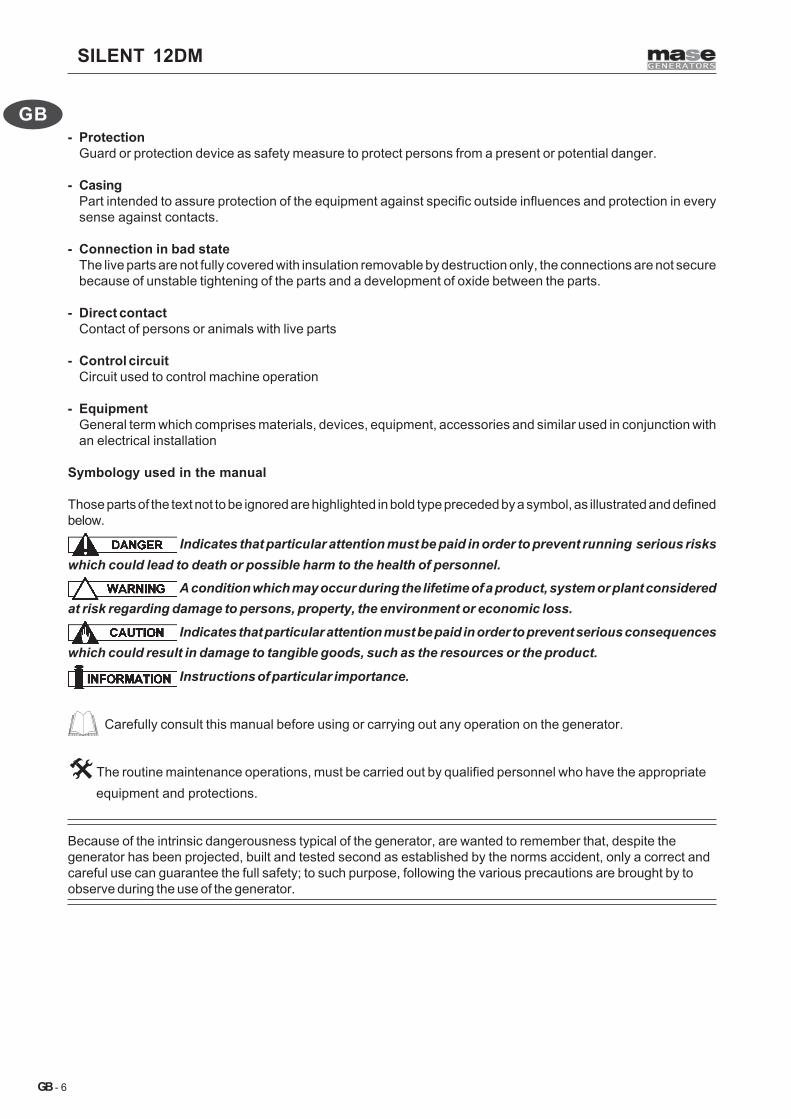
Symbology used in the manual
Those parts of the text not to be ignored are highlighted in bold type preceded by a symbol, as illustrated and definedbelow.
Indicates that particular attention must be paid in order to prevent running serious riskswhich could lead to death or possible harm to the health of personnel.
A condition which may occur during the lifetime of a product, system or plant consideredat risk regarding damage to persons, property, the environment or economic loss.
Indicates that particular attention must be paid in order to prevent serious consequenceswhich could result in damage to tangible goods, such as the resources or the product.
Instructions of particular importance.
Carefully consult this manual before using or carrying out any operation on the generator.
The routine maintenance operations, must be carried out by qualified personnel who have the appropriate equipment and protections.
Because of the intrinsic dangerousness typical of the generator, are wanted to remember that, despite thegenerator has been projected, built and tested second as established by the norms accident, only a correct andcareful use can guarantee the full safety; to such purpose, following the various precautions are brought by toobserve during the use of the generator.
SILENT 12DM
- 7
GB
GB
PRELIMINARY PRESCRIPTIONS
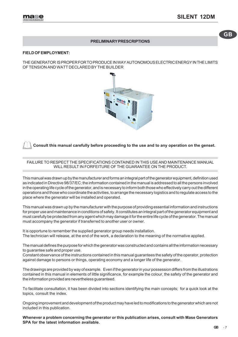
FIELD OF EMPLOYMENT:
THE GENERATOR IS PROPER FOR TO PRODUCE IN WAY AUTONOMOUS ELECTRIC ENERGY IN THE LIMITSOF TENSION AND WATT DECLARED BY THE BUILDER
Consult this manual carefully before proceeding to the use and to any operation on the genset.
FAILURE TO RESPECT THE SPECIFICATIONS CONTAINED IN THIS USE AND MAINTENANCE MANUALWILL RESULT IN FORFEITURE OF THE GUARANTEE ON THE PRODUCT.
This manual was drawn up by the manufacturer and forms an integral part of the generator equipment, definition usedas indicated in Directive 98/37/EC; the information contained in the manual is addressed to all the persons involvedin the operating life cycle of the generator, and is necessary to inform both those who effectively carry out the differentoperations and those who coordinate the activities, to arrange the necessary logistics and to regulate access to theplace where the generator will be installed and operated.
This manual was drawn up by the manufacturer with the purpose of providing essential information and instructionsfor proper use and maintenance in conditions of safety. It constitutes an integral part of the generator equipment andmust carefully be protected from any agent which may damage it for the entire life cycle of the generator. The manualmust accompany the generator if transferred to another user or owner.
It is opportune to remember the supplied generator group needs installation.The technician will release, at the end of the work, a declaration to the meaning of the normative applied.
The manual defines the purpose for which the generator was constructed and contains all the information necessaryto guarantee safe and proper use.Constant observance of the instructions contained in this manual guarantees the safety of the operator, protectionagainst damage to persons or things, operating economy and a longer life of the generator.
The drawings are provided by way of example. Even if the generator in your possession differs from the illustrationscontained in this manual in elements of little significance, for example the colour, the safety of the generator andthe information provided are nevertheless guaranteed.
To facilitate consultation, it has been divided into sections identifying the main concepts; for a quick look at thetopics, consult the index.
Ongoing improvement and development of the product may have led to modifications to the generator which are notincluded in this publication.
Whenever a problem concerning the generator or this publication arises, consult with Mase GeneratorsSPA for the latest information available.

SILENT 12DM
- 8
GB
GB
Cod. 41779
Cod. 42352
Cod. 41775
Cod. 41781 Cod. 41776
EEL L
STOP
ES
DI
ES
ID
Cod. 42351
MACCHINA AD AVVIAMENTOAUTOMATICO A DISTANZA
STARTINGAUTOMATIC REMOTE
FERNSTARTVORRICHTUNG
AUTOMATICA A DISTANCIAMACHINE A DEMARRAGEAUTOMATIQUE A DISTANCE
I
GB
D
E
F
Cod. 42347
Cod. 41776cod. 42112
Cod. 41777
Cod. 42118
Cod. 41810
1. GENERAL SAFETY WARNINGS
1.1 Symbols on the generator

SILENT 12DM
- 9
GB
GB
MACCHINA AD AVVIAMENTOAUTOMATICO A DISTANZA
STARTINGAUTOMATIC REMOTE
FERNSTARTVORRICHTUNG
AUTOMATICA A DISTANCIAMACHINE A DEMARRAGEAUTOMATIQUE A DISTANCE
I
GB
D
E
F
1.2 Position of safety labels
• These labels warn the user of any danger which may cause serious injury.Carefully read the meaning and the precautions described in this manual.
• If the label detaches or becomes illegible, replace it with a new one which can be requested from an authorisedmase dealer.
Danger Symbols Meaning
- Caution to avoid burns, do not touch during operation.The exhaust manifold and the engine, pay attention to the labels on the generator.
- Leave the engine to cool down before storing it indoors
- Read and understand the Use and Maintenance Manual before starting thegenerator.
- The Mase generator has been designed so as to guarantee safe and reliableoperation provided that the instructions are followed. Otherwise,personal injury ordamage to the equipment may result.
- Exhaust gas contain carbon monoxide, that is toxic.- Don’t turn on the generator in a closed place.- Provide to a good ventilation. If installed indoors, scrupulously observe the
ventilation regulations.
- Danger of electric discharge: consult the manual
- Danger of sudden starting from the remote control panel.- Before doing any operation on the genset, disarm the remote starting system.
- Danger of electric shock: consult the manual
- Danger of burns: Hot surfaces
- Danger of entangle and cut: presence of rotating parts, pulleys, belts, fan.
- Danger of burns: possibility of expulsion of hot water in pressure.

SILENT 12DM
- 10
GB
GB
- Danger possible spillages of corrosive acid.
- The connections to an emergency electric net must be effected by specializedelectricians and accordingly to the relating norms. Improper connections cancause current return from the generator to the connected electric lines. That cancause electric discharge on those people who works for the electric company orcomes contact with the lines during the breakdown. When the line is rehabilitated,the generator can explodes, burns or causes fires in the electric line system.
- No smoking or use of open flames.
- Do not clean, lubricate, repair or adjust moving parts.
- Do not extinguish fires with water, use homologated extinguishers.
Obligation Symbols Meaning
Prohibition Symbols Meaning
- Obligation to connect the generator group to earth.
Information Symbols Meaning
- It indicates the dip stick location for the control of the oil level engine.
- It indicates the location of a point of lifting of the generator group.
SILENT 12DM
- 11
GB
GB
1.3 General danger informations
• It is recommended to learn how to stop and operate all the controls.• Do not allow unqualified personnel to use the generator.• Even though the generator is protected, do not stand near it.• Do not remove the labels for any reason and request replacement if necessary.
• Before starting the Generator or before starting any lubrication or maintenance operation, it is essential that thepersonnel responsible has read and understood all the WARNINGS, CAUTION and DANGER notices in thismanual and in the additional technical documentation provided.
• Before any operation on the generator, ensure that the primary engine is not running and that no parts are moving,and post a sign saying DO NOT SWITCH ON or similar at the start switch or the controls before carrying out themaintenance or repair work on the generator.
• Nevertheless, the manufacturer cannot foresee all the possible circumstances which may lead to potential risksin the effective conditions of use of the Generator.Any operations and/or procedures for maintenance not expressly recommended or indicated in the user manualsmust always be notified to and approved by the manufacturer.In the event that a procedure not specifically recommended needs to be applied, the user is responsible for assuringthat such procedure is safe and does not cause harm to persons.
• The manufacturer declines all responsibility for damage to persons or things deriving from inobservance of thesafety regulations.
• Carefully examine the safety warning plates on the generator and respect the relevant instructions.
1.3.1 Danger of entanglement
• Do not remove the original protections from any of the exposed rotating parts, hot surfaces, air intakes, belts andlive parts.
• Do not carry out any maintenance operation with the generator running.• Do not wear flapping garments, such as scarves, foulards, bracelets, etc. and all garments must be tied with elastic
at the edges.• Do not clean or carry out maintenance on moving parts
1.3.2 Danger of burns
• Do not permit unskilled persons or without adequate training to use the generator.• Do not permit children or animals to approach the generator when it is in operation.• Never touch the exhaust, the relevant protection or the engine body when the generator is running or still hot.• Do not lean against or sit on the generator for any reason whatsoever.• Identify the position of the fire extinguishers or other protection and emergency devices and learn their functioning.• Identify any sources of danger such as fuel, engine oil or acid solution leaks, condensate in the drip caps, high
voltage, high pressure.• Do not cause short-circuits by placing keys or tools on the batteries or on the cable fittings.• The battery fluid contains sulphuric acid which is extremely corrosive and harmful to the skin. Always wear
protective gloves and be extremely careful to avoid spillage when pouring the acid. In the event of contact, washthe affected part thoroughly with running water and consult a physician, in particular when the eyes are involved.
SILENT 12DM
- 12
GB
GB
1.3.3 Danger of harm to hearing
• Do not stand near the generator for long periods without protective earmuffs since hearing may be reduced.
1.3.4 Danger of intoxication
• The exhaust gases contain toxic carbon monoxide.• Never use the generator in tunnels or in any place with poor ventilation. If indoor use is inevitable, it is essential
to provide for proper and efficient ventilation in order to prevent intoxication of persons or animals.• Check that the engine exhaust is free and that the pipes allow evacuation of the exhaust fumes.• Check that the exhaust gases are discharged to the outside in a safe position away from doors, windows and air
intakes.
1.3.5 Danger of fire or explosion
• Always turn off the engine before refuelling.• Do not smoke during refuelling.• Refuelling must be carried out with extreme care, ensuring that fuel does not overflow from the engine tank
respecting the maximum level.• In the event of fuel spillage from the tank, thoroughly dry and clean the parts involved.• Check that there are no fuel leaks and that the pipes are undamaged.• When refuelling has been completed, tightly close the fillercap• Keep flammable liquids, matches and other explosive and/or flammable products away from the generator, since
the temperature near the exhaust is high during operation.• Never leave flammable liquids or cloths soaked in flammable liquids in proximity of electrical equipment (including
lamps) or parts of the electrical system.• The batteries develop hydrogen, a highly explosive gas. It is recommended not to smoke nor cause sparks in the
vicinity, in particular during charging.• Do not obstruct the cooling air inlets/outlets.• In the event of fire, use a homologated fire extinguisher and never use water.
1.3.6 Danger if failing to use personal protection devices
• The persons responsible for handling must always wear protective gloves and safety shoes.• Wear safety shoes and overalls.• If the generator needs to be lifted from the ground, the operators must wear a protective helmet.• Immediately change wet overalls.• Use protective gloves.
1.3.7 Danger caused by the engine starting
• Do not leave disassembled parts, tools or anything else not forming part of the system on or near the engine.• Install the protections necessary for safety on the parts completing the system.• Operate the generator on a flat surface as far as possible. For continuous operation, the maximum permitted engine
inclination is 20 degrees. Greater inclination of the generator might cause the fuel to leak out or cause problems with engineoil pressure.

SILENT 12DM
- 13
GB
GB
• To prevent the risk of fire and for proper ventilation, position the generator at least 1m (3 ft) from buildings or other equipmentduring operation.
• Check the oil level by means of the dipstick.• Check that all the electrical utilities are off so that the generator is not started on load.• Check perfect functioning of the devices which stop the generator in the event of failure due to low oil level.• Identify the position of the emergency stop buttons, switches and other emergency systems on the generator.• Learn the special emergency procedures relative to the installation in question.
1.3.8 Danger of electromagnetic radiation
• Do not allow access to persons wearing a pacemaker because of possible electromagnetic interference with the device.
1.3.9 Danger of electrocution
• When using the generator always bear in mind that in wet or very humid places and in confined conduction spaces it isobligatory to comply with Articles 313 and 318 of Presidential Decree No. 547 27/04/55, as well as Chap. 11 Section IVof the CEI 64-8 regulation.
• Immediately change wet overalls.• Insulate all the connectors and detached wires.• Do not leave the power terminal board of the generator uncovered; check that the electrical power and auxiliary service
connections have been made properly.• Do not power loads with a voltage different from that delivered by the generator• Do not spray water directly onto the electrical parts• Do not clean the internal electrical parts with compressed air, since short-circuits or other faults may occur.
Do not tamper with the active protections, thermal switches and differential magnetothermal switches.• In the event of malfunctioning, do not remove the panel to attempt repairing it. Contact Mase specialised personnel.• Do not access the generator with wet hands, since it is a potential source of electric shock if improperly used.• Take the necessary precautions to prevent the danger of electrocution; check that the earthing system has been installed
and constructed in accordance with regulations.• For the safety of the users, the earth connection of the generator must always be carried out paying particular attention
to the cable cross-section used. For the connection of the earth cable use the dedicated terminal on the generator. Forthe earth connection follow the indications in the table to select the cable cross-section to use depending on the generatorpower.
The manufacturer is not responsible for any damage caused by failure to earth the system.
1.3.10 Danger resulting from bad storage
• Packed and unpacked generators must be stored in a cool and dry place and never exposed to bad weather.• Avoid stacking packed generators to prevent them from falling causing damage to persons and/or things.

SILENT 12DM
- 14
GB
GB
KVAHz
Cos.Ø
V VA A
Degrees of protection IP
°Cm
Performance classyear of manifacture
Rated power factorRated voltage
declared frequency
Mass Kg
Class of insulationTemp. max of useAltitude max. of use
Rated current
Rated power 3FCode Serial n°
1
2
54
14
67
89
1011
12
13
15
16
3
Fig.A
1.4 Reference documents
The instructions for use provided with each generator aremade up of a collection of documents of which this manualrepresents the General Part. The following documents arenormally provided separate.
a CE declaration of conformity.b Instruction manual for use and maintenance of the
generators,(this manual).
c Engine use and maintenance manual.d List of mase Service Centres.e Mase Warranty certificate.f Warranty card.
1.5 Reference regulations and legislative provisions
The generator groups, built by mase, destined to thecountries of the European Community, are conforming tothe applicable EC directives, and they are provided of a ECDeclaration of Conformity.
98/37/EC and subsequent amendments:Essential machine requirements for safety and healthprotection (“Machine” directive).
73/23/EC and subsequent amendments contained in thedirective 93/68/EC: Guarantee of safety of electricalmaterial intended for use within certain voltage limits,(“Low Voltage” Directives).
EN 12601: Generator groups moved by internalcombustion engine.
EN 60204.1: Electric equipments of the generator groups.
1.6 Marking
The generator identification plate carries all theidentification data in conformity to ISO 8528 and inaccordance with the provisions for CE Marking for thosecases where required. Below is a facsimile of theidentification plate fixed on the hull of each generator(fig.A).
1.7 Identification of the generator unit
1 - Machine name2 - Machine code3 - Serial number4 - Rated power5 - Declared frequency6 - Rated power factor7 - Rated voltage8 - Rated current9 - Degree of protection10 - Class of isolation11 - Temperature max. of use12 - Altitude max. of use13 - Performance class14 - Year of construction15 - Manufacturer - Adress16 - Weight
The machine code number, the serial numberand the year of construction must always beindicated when contacting the manufacturer forinformation, order of spare parts, etc..
SILENT 12DM
- 15
GB
GB
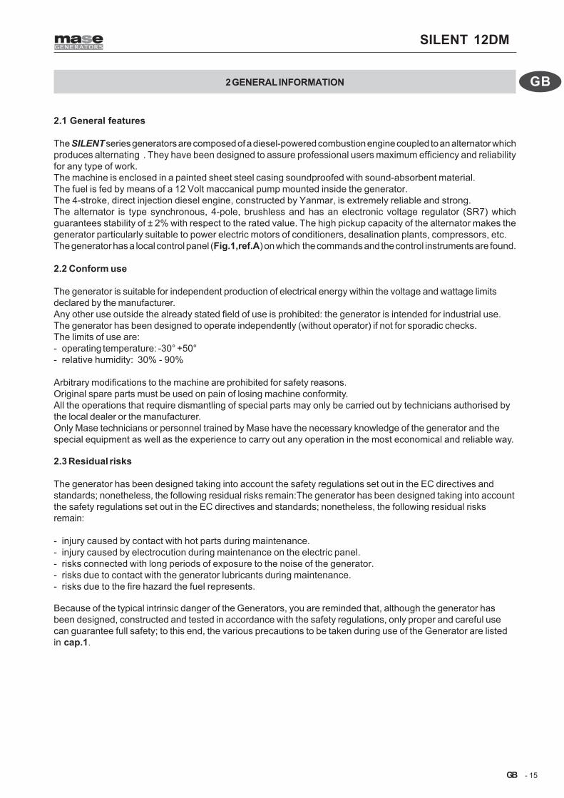
2.1 General features
The SILENT series generators are composed of a diesel-powered combustion engine coupled to an alternator whichproduces alternating . They have been designed to assure professional users maximum efficiency and reliabilityfor any type of work.The machine is enclosed in a painted sheet steel casing soundproofed with sound-absorbent material.The fuel is fed by means of a 12 Volt maccanical pump mounted inside the generator.The 4-stroke, direct injection diesel engine, constructed by Yanmar, is extremely reliable and strong.The alternator is type synchronous, 4-pole, brushless and has an electronic voltage regulator (SR7) whichguarantees stability of ± 2% with respect to the rated value. The high pickup capacity of the alternator makes thegenerator particularly suitable to power electric motors of conditioners, desalination plants, compressors, etc.The generator has a local control panel (Fig.1,ref.A) on which the commands and the control instruments are found.
2.2 Conform use
The generator is suitable for independent production of electrical energy within the voltage and wattage limitsdeclared by the manufacturer.Any other use outside the already stated field of use is prohibited: the generator is intended for industrial use.The generator has been designed to operate independently (without operator) if not for sporadic checks.The limits of use are:- operating temperature: -30° +50°- relative humidity: 30% - 90%
Arbitrary modifications to the machine are prohibited for safety reasons.Original spare parts must be used on pain of losing machine conformity.All the operations that require dismantling of special parts may only be carried out by technicians authorised bythe local dealer or the manufacturer.Only Mase technicians or personnel trained by Mase have the necessary knowledge of the generator and thespecial equipment as well as the experience to carry out any operation in the most economical and reliable way.
2.3 Residual risks
The generator has been designed taking into account the safety regulations set out in the EC directives andstandards; nonetheless, the following residual risks remain:The generator has been designed taking into accountthe safety regulations set out in the EC directives and standards; nonetheless, the following residual risksremain:
- injury caused by contact with hot parts during maintenance.- injury caused by electrocution during maintenance on the electric panel.- risks connected with long periods of exposure to the noise of the generator.- risks due to contact with the generator lubricants during maintenance.- risks due to the fire hazard the fuel represents.
Because of the typical intrinsic danger of the Generators, you are reminded that, although the generator hasbeen designed, constructed and tested in accordance with the safety regulations, only proper and careful usecan guarantee full safety; to this end, the various precautions to be taken during use of the Generator are listedin cap.1.
2 GENERAL INFORMATION
SILENT 12DM
- 16
GB
GB
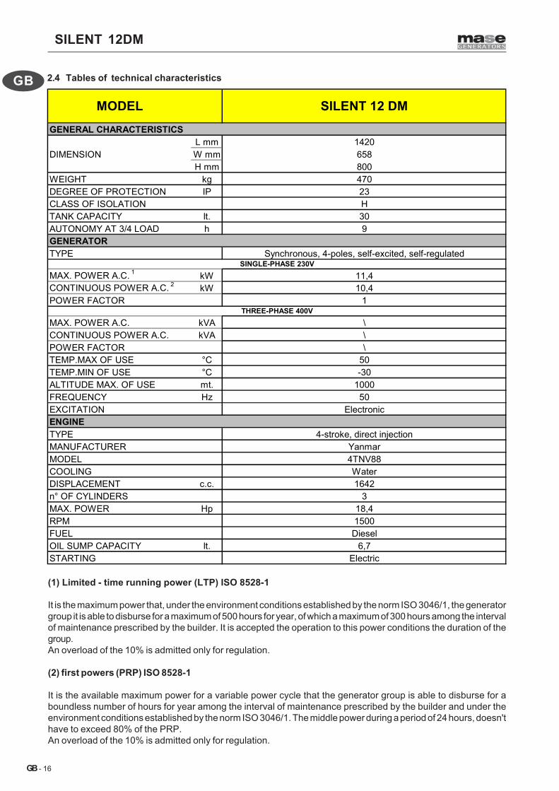
(1) Limited - time running power (LTP) ISO 8528-1
It is the maximum power that, under the environment conditions established by the norm ISO 3046/1, the generatorgroup it is able to disburse for a maximum of 500 hours for year, of which a maximum of 300 hours among the intervalof maintenance prescribed by the builder. It is accepted the operation to this power conditions the duration of thegroup.An overload of the 10% is admitted only for regulation.
(2) first powers (PRP) ISO 8528-1
It is the available maximum power for a variable power cycle that the generator group is able to disburse for aboundless number of hours for year among the interval of maintenance prescribed by the builder and under theenvironment conditions established by the norm ISO 3046/1. The middle power during a period of 24 hours, doesn'thave to exceed 80% of the PRP.An overload of the 10% is admitted only for regulation.
2.4 Tables of technical characteristics
GENERAL CHARACTERISTICSL mm 1420
DIMENSION W mm 658H mm 800
WEIGHT kg 470DEGREE OF PROTECTION IP 23CLASS OF ISOLATION HTANK CAPACITY lt. 30AUTONOMY AT 3/4 LOAD h 9GENERATORTYPE Synchronous, 4-poles, self-excited, self-regulated
MAX. POWER A.C. 1 kW 11,4CONTINUOUS POWER A.C. 2 kW 10,4POWER FACTOR 1
MAX. POWER A.C. kVA \CONTINUOUS POWER A.C. kVA \POWER FACTOR \TEMP.MAX OF USE °C 50TEMP.MIN OF USE °C -30ALTITUDE MAX. OF USE mt. 1000FREQUENCY Hz 50EXCITATION ElectronicENGINETYPE 4-stroke, direct injectionMANUFACTURER YanmarMODEL 4TNV88COOLING WaterDISPLACEMENT c.c. 1642n° OF CYLINDERS 3MAX. POWER Hp 18,4RPM 1500FUEL DieselOIL SUMP CAPACITY lt. 6,7STARTING Electric
MODEL SILENT 12 DM
THREE-PHASE 400V
SINGLE-PHASE 230V
SILENT 12DM
- 17
GB
GB
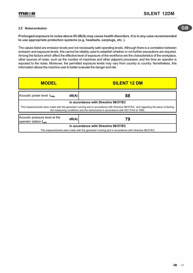
2.5 Noise emission
Prolonged exposure to noise above 85 dB(A) may cause health disorders. It is in any case recommendedto use appropriate protection systems (e.g. headsets, earplugs, etc. ).
The values listed are emission levels and not necessarily safe operating levels. Although there is a correlation betweenemission and exposure levels, this cannot be reliably used to establish whether or not further precautions are required.Among the factors which affect the effective level of exposure of the workforce are the characteristics of the workplace,other sources of noise, such as the number of machines and other adjacent processes, and the time an operator isexposed to the noise. Moreover, the permitted exposure levels may vary from country to country. Nonetheless, thisinformation allows the machine user to better evaluate the danger and risk.
Acoustic power level LWA dB(A) 88
Acoustic pressure level at the operator station LpA
dB(A) 79in accordance with Directive 98/37/EC
The measurements were made with the generator running and in accordance with Directive 98/37/EC
SILENT 12 DM
in accordance with Directive 98/37/ECThe measurements were made with the generator running and in accordance with Directive 98/37/EC, and regarding the place of testing,
the measuring conditions and the instruments in accordance with ISO 3744 of 1995.
MODEL

SILENT 12DM
- 18
GB
GB
4
6
Fig.1
2
5
1
3
1
2
3
4
5
6
1
2
3
“C”
“B”
“A”
7
8
2.7 Generator composition
See Fig.1,ref.AThe generators are essentially composed of thefollowing components:
1 Fixed frame2 Engine side chest3 Lock with key4 Engine5 Alternator6 Emergency button
2.8 Control panel and onboard instrument panel
See Fig.1 ref.BEach generator is fitted with an instrument panel for thecontrols with the following components:
1 - Low voltage termal switch2 - “RUN” warning light, engine on3 - General magnetothermal switch 63A, 2P4 - Earth connection5 - EC socket 32A 400V, 3P+N+T6 - Automatic starting control panel socket7 - Engine Heater Socket8 - Magnetothermal switch 32A, 2P+T
2.9 Remote control panel
See Fig.1 ref.CThe generator is set up to be connected via connectorto the remote starting panel supplied by mase.
1 - Remote control panel2 - Fuel level3 - Emergency button
SILENT 12DM
- 19
GB
GB
Fig.2
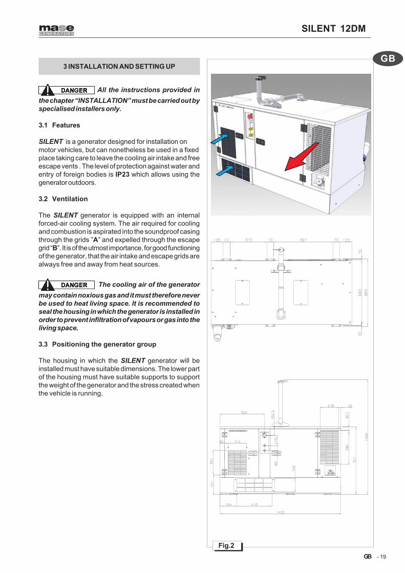
3 INSTALLATION AND SETTING UP
All the instructions provided inthe chapter “INSTALLATION” must be carried out byspecialised installers only.
3.1 Features
SILENT is a generator designed for installation onmotor vehicles, but can nonetheless be used in a fixedplace taking care to leave the cooling air intake and freeescape vents . The level of protection against water andentry of foreign bodies is IP23 which allows using thegenerator outdoors.
3.2 Ventilation
The SILENT generator is equipped with an internalforced-air cooling system. The air required for coolingand combustion is aspirated into the soundproof casingthrough the grids ”A” and expelled through the escapegrid “B”. It is of the utmost importance, for good functioningof the generator, that the air intake and escape grids arealways free and away from heat sources.
The cooling air of the generatormay contain noxious gas and it must therefore neverbe used to heat living space. It is recommended toseal the housing in which the generator is installed inorder to prevent infiltration of vapours or gas into theliving space.
3.3 Positioning the generator group
The housing in which the SILENT generator will beinstalled must have suitable dimensions. The lower partof the housing must have suitable supports to supportthe weight of the generator and the stress created whenthe vehicle is running.
SILENT 12DM
- 20
GB
GB
1
EXTERNALFUELTANK
ENGINE
INTERNALTANKFUEL
ENGINE
EXTERNALFUELTANK
DISCONNECT
CONNECT
FOR USE
EXTERNALTANKFUELFOR USE
Fig.3
2
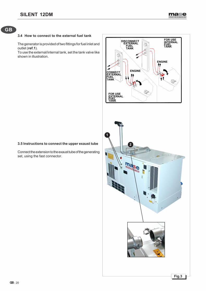
3.4 How to connect to the external fuel tank
The generator is provided of two fittings for fuel inlet andoutlet (ref.1).To use the external/internal tank, set the tank valve likeshown in illustration.
3.5 Instructions to connect the upper exaust tube
Connect the extension to the exaust tube of the generatingset, using the fast connector.

SILENT 12DM
- 21
GB
GB
Fig.4
3
4
1
2
3.6 Electrical connection instructions
Connect the automatic control panel to the generatorthrought the connector (ref.1).Use a certified cable, with the correct section.In the control panel (ref.2), connect the electricity inputusing the EC 63A 230V socket (ref.3).Connect to ground using the provided screw (ref.4).See the attached wiring diagram.
3.7 Connecting to the remote control panel
In the control panel, connect the network input (ref.2) tothe electrical network; connect the output to the loads.Connect to ground using the provided screw (ref.4).See the attached wiring diagram.
In case of maintenance interventions on the generator,disconnect the positive pole of the starting battery,avoiding in this way accidental starting.
SILENT 12DM
- 22
GB
GB
Fig.5
4
3
2
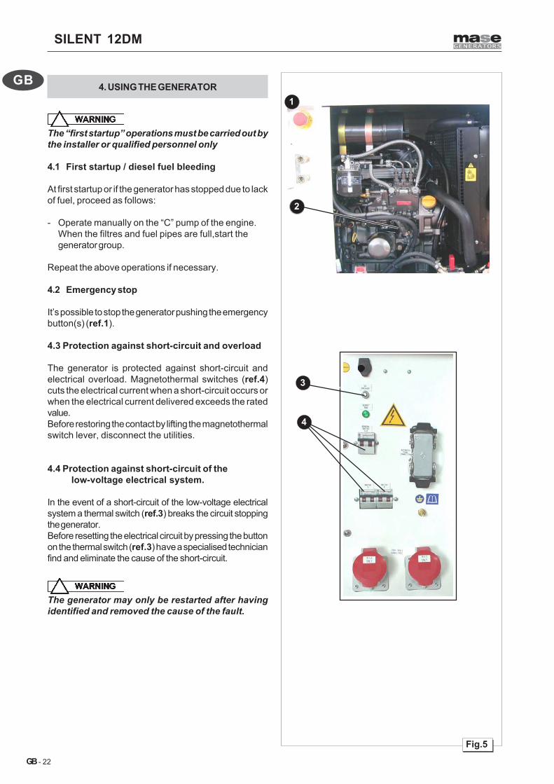
14. USING THE GENERATOR
The “first startup” operations must be carried out bythe installer or qualified personnel only
4.1 First startup / diesel fuel bleeding
At first startup or if the generator has stopped due to lackof fuel, proceed as follows:
- Operate manually on the “C” pump of the engine.When the filtres and fuel pipes are full,start thegenerator group.
Repeat the above operations if necessary.
4.2 Emergency stop
It’s possible to stop the generator pushing the emergencybutton(s) (ref.1).
4.3 Protection against short-circuit and overload
The generator is protected against short-circuit andelectrical overload. Magnetothermal switches (ref.4)cuts the electrical current when a short-circuit occurs orwhen the electrical current delivered exceeds the ratedvalue.Before restoring the contact by lifting the magnetothermalswitch lever, disconnect the utilities.
4.4 Protection against short-circuit of the low-voltage electrical system.
In the event of a short-circuit of the low-voltage electricalsystem a thermal switch (ref.3) breaks the circuit stoppingthe generator.Before resetting the electrical circuit by pressing the buttonon the thermal switch (ref.3) have a specialised technicianfind and eliminate the cause of the short-circuit.
The generator may only be restarted after havingidentified and removed the cause of the fault.

SILENT 12DM
- 23
GB
GB
4.5 Quick guide to the use of“Automatic starting control panel”
For more informations, consult the “Installation manual”provided with the generator.BE features Automatic Mains Failure and GeneratingSet control and monitoring. The BE provides visualindication by means of LEDs and Display Messages forthe following:
4.6 Operating mode selectionBy using the [MODE-UP] and [MODE-DOWN]pushbuttons it is possible to select TEST, AUTO,MANUAL or RESET operating modes. The operatingmodes are indicated by means of yellow LEDs.Every time the power supply is switched on, the BEenters automatically into RESET operating mode.
4.7 TEST operating modeIn TEST operating mode, BE starts the engine.When the genset is running the load will be transferredfrom the main net to the genset.All the alarms are controlled.To stop the engine, the user must select the 'AUTO'(automatic) operating mode: if the Mains stays within theprogrammed settings the engine will stop after theprogrammed 'COOLING DOWN' time.In alternative the engine can be stopped with the MANUAL(manuale) operating mode by pressing the [STOP]pushbutton.NOTE:In case of emergency it is possible to use the[STOP] pushbutton in 'AUTO' or 'TEST' operating modes.This case will generate the 'ALARM2' alarm to indicatea stop due to the manual emergency stop. To clear the'ALARM 2' it is necessary to select the 'RESET' operatingmode.
4.8 AUTO operating mode (automatic)The automatic sequences are activated by absence ofthe main voltage.In “AUTO” operating mode, the BE can drive periodicallythe engine start.During the automatic periodic test the operating modeLEDs will continue to flash.
4.9 MANUAL operating modeThe MANUAL operating mode allows the 'Off-Load' useof the Engine by means of the [START] and [STOP]pushbuttons. To start the engine push the [START]pushbutton until engine starts. To stop the engine pushthe [STOP] pushbutton until the [STOP] message appearson the display. The BE drives the programmed 'STOP-cycle'.If the "STOP-cycle" is very long it is possible to cancelit by pressing again the button of [Stop] (only if theengine is still stopped). The BE transfers the Load onlyto 'AUTO” (automatic) or “TEST” operating mode.
4.10 RESET operating mode (alarmscancellation)This operating mode clears the fault alarms and resetsthe BE.If the BE stays in 'RESET' operating mode for morethan 5 minutes, the Display and LEDs are turned offautomatically (low power consumption mode).To set the normal operating mode push the [MODE-UP] or [MODE-DOWN] pushbuttons.In RESET operating mode, the contact breaker of mainnetwork is forced closed indipendently from the state ofthe main.
4.11 START-STOP pushbuttonsThese pushbuttons are used to start and stop theengine.In 'AUTO' or 'TEST' operating modes, the [STOP]pushbutton will produce an emergency stop and generatesthe 'ALARM 2' alarm.
4.12 DISPLAY featuresThe BE features a 4 Digit Display to show parametersettings,measurements and error messages. The[DISPLAY-UP] and [DISPLAY-DOWN] pushbuttonsselect one of the following menu:h(hourcounter)-AMPERE(Generator current)-VOLTAGE

SILENT 12DM
- 24
GB
GB
(Generator voltage or Main voltage)-FREQUENCY-BATTERY(Battery voltage or alternator charge voltage).Each menu is indicated by means of a yellow LED.The operative modes list follows:h If the operating mode selected is “MAN” (manual),“AUTO” (automatic) or “TEST”, the Display shows the‘HOUR COUNT’ of the electrogen group.If the operating mode is “RESET”, display indicates theprogrammable parameters.CURRENT: The Generator Current measurement isdisplayed up to 1000Aac.VOLTAGE: The Voltage of the MAINS or GEN-SET isdisplayed. If the fuel solenoid is energised (due to a startrequest) the display shows the voltage of the generator.Otherwise, the display shows the voltage of the Mains.The range is 80Vac up to 500Vac.To avoid confusion, the GENERATOR voltage isdisplayed like [GXXX] and the MAINS voltage like[MXXX] (XXX indicates an entire number of threedigits).FREQUENCY: The Frequency measurement of theGenerator is displayed. The resolution of measure is0.1Hz. The reading of the measure is activated withgenerator voltage up than 80 Vac.BATTERY: The Battery or Charger Alternator voltagesare displayed. The display shows,normally, the batteryvoltage. By pushing and holding the [DISPLAY-DOWN]pushbutton the Charger Alternator voltage is displayed.
4.13 DISPLAY messagesSome alarms are displayed by means of a message‘EXX’. ‘E’ is the indication of error or alarm, ‘XX’ meansa number or a code. The BE can show the following:[E 01] (OVER-FREQUENCY). The source of the alarmcomes from the frequency of the Generator. The protectionis delayed by 2 seconds. The alarm is always controlled.[E 02] (BELT BREAK). There is a ‘Belt Break’ alarmwhen the alternator of battery charge doesn’t give voltage.The alarm is delayed by 20 seconds to prevents falsetrigger of the alarm.[E 03] (EXTERNAL BLOCK). The BE actives a “STOPCYCLE” and blocks all the functions.[E 04] (ALTERNATOR FAILURE). E04 comes displayedif the voltage or the frequency of the alternator lacks for150 seconds after the engine has been started.The engine will be stopped.[E 05] (GEN-SET OVERLOAD). If the current of theGenerator is over the setting for at least 6 seconds, theengine will be stopped.In “AUTO” operating mode the engine will be stoppedafter cooling down time. In “MAN” operating mode theengine will be stopped immediately.[E 06] (UNDER FREQUENCY) The protection is delayedby 6 seconds and works only if the contactor is closed(AUTO or TEST operating modes).The engine shuts down after a cooling down time.[Hi U] (OVER VOLTAGE) If the Generator voltage is overthe setting for at least 2 seconds, will be displayed themessage [Hi-U],
[Lo U] (UNDER VOLTAGE or SHORT CIRCUIT) Thealarm energises only with contactor of the generatorclosed (“AUTO” or “TEST” operating mode) if:- the voltage drops under the setting for more than 6seconds- the voltage drops under the setting (minus 20%) formore than 1 secondThe BE opens the contactor of the Generator and stopsthe engine after the cooling down time.[Err ] (MEMORY ERROR) This message indicates aninternal failure of the memory. It is possible to restore thenormal operating mode of the memory by disconnectingthe battery and re-connect it supply after some minutes.BE features additional messages to inform aboutparticular functions:[M-on] (MAINS SIMULATION).[‘ ‘ ‘ ‘] (GLOW PLUGS). The BE21 is driving the GLOWPLUGS.[——] (V-METER out of range). The voltage (Mains orGenerator) drops under 80Vac (over scale)[StA-] (START). The BE is driving the start cycle.[StOP] (STOP). The BE is driving the stop cycle.
4.14 LEDs for visual indicationsLOW OIL PRESSURE [Red LED]. Indication of Low OilPressure alarm.HIGH ENGINE TEMPERATURE [Red LED]. Indicationof High Temperature alarm.STARTING FAILURE [Red LED]. This alarm is activatedif the engine does not start after a complete startingcycle.OVERLOAD [Red LED]. When active, is displayedOVERLOAD alarm. The connector will open and theengine will shut down.BATTERY [Yellow LED]. The alarm settings are set to11,8/15.0V. The alarm is delayed by 120 seconds toavoid false interventions.ALARM 1, ALARM 2 [Red LEDs]. These are indicationsof Alarm1 e Alarm2.‘ALARM 1’ is by-passed timer after the engine has beenstarted. ‘ALARM 2’ is due also by using the STOPpushbutton in “AUTO” or “TEST” operation mode.ENGINE RUN [Green LED]. Engine runningFUEL [Yellow LED]. This is an optical warning indicationof Low Level Fuel.The generating set stops if the contact stays closedfor at least 5 minutes continuously.CONTACTOR of the MAINS ‘KM’(green LED illuminated=CLOSED)CONTACTOR of the GENERATOR ‘KG’(green LED illuminated=CLOSED)

SILENT 12DM
- 25
GB
GBFig.7
6
3
52
7
8
4
5. CARE AND MAINTENANCE
5.1 Preamble
Before starting maintenance work on the generator,lock it by pressing the emergency button!
Failure to observe this procedure, may result inaccidental starting!
Any maintenance operation on the generator or theelectrical line must be carried out with the engine offafter leaving it to cool down sufficiently and afterdisconnecting the battery from the generator.This type of operation must be carried out byauthorised and duly trained personnel.
It is recommended to scrupulously follow the instructionsin the manual provided by the engine manufacturer witheach generator.It is important to regularly inspect and carry outmaintenance on the generator. The frequency ofmaintenance should be decided on the basis of thenumber of hours of operation.
5.2 Ordinary engine maintenance
The periodic maintenance operations to be carried outon the engine are indicated in the table in point fig.8. Formore detailed information consult the manual providedby the engine manufacturer with each generator.
- Check the oil level with the cap/dipstick (fig.7ref.2).The oil level must always be between the MAX andMIN notches on the dipstick (fig.7ref.4).
- When checking the oil level, ensure that thegenerator is positioned horizontally.
5.3 Engine oil change
Use diesel engine oilTop-up and fill through the hole indicated in fig.7 ref.3.For detailed information in this connection, consult theengine use and maintenance manual which accompaniesthe machine.It is recommended to drain the oil when it is stillsufficiently warm to flow easily.
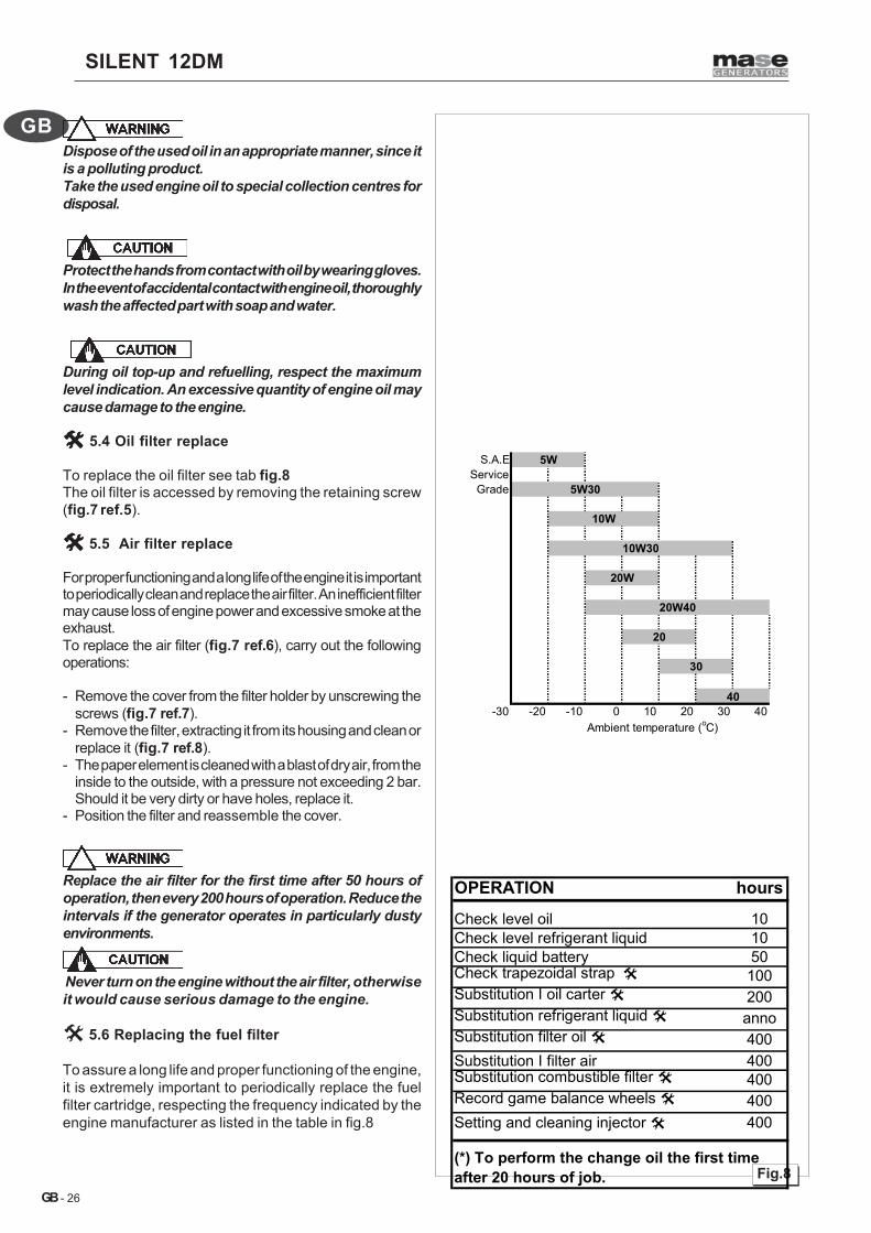
Always check correct viscosity of the engine oil inrelation to the range of ambient temperatures in whichthe generator operates as indicated in the table.
SILENT 12DM
- 26
GB
GB
Fig.8
S.A.EService
Grade
-30 -20 -10 0 10 20 30 40Ambient temperature (oC)
40
20W
20W40
20
30
5W
5W30
10W
10W30
OPERATION hours
Check level oil 10Check level refrigerant liquid 10Check liquid battery 50Check trapezoidal strap 100Substitution I oil carter 200Substitution refrigerant liquid annoSubstitution filter oil 400Substitution I filter air 400Substitution combustible filter 400Record game balance wheels 400Setting and cleaning injector 400
(*) To perform the change oil the first time after 20 hours of job.
Dispose of the used oil in an appropriate manner, since itis a polluting product.Take the used engine oil to special collection centres fordisposal.
Protect the hands from contact with oil by wearing gloves.In the event of accidental contact with engine oil, thoroughlywash the affected part with soap and water.
During oil top-up and refuelling, respect the maximumlevel indication. An excessive quantity of engine oil maycause damage to the engine.
5.4 Oil filter replace
To replace the oil filter see tab fig.8The oil filter is accessed by removing the retaining screw(fig.7 ref.5).
5.5 Air filter replace
For proper functioning and a long life of the engine it is importantto periodically clean and replace the air filter. An inefficient filtermay cause loss of engine power and excessive smoke at theexhaust.To replace the air filter (fig.7 ref.6), carry out the followingoperations:
- Remove the cover from the filter holder by unscrewing thescrews (fig.7 ref.7).
- Remove the filter, extracting it from its housing and clean orreplace it (fig.7 ref.8).
- The paper element is cleaned with a blast of dry air, from theinside to the outside, with a pressure not exceeding 2 bar.Should it be very dirty or have holes, replace it.
- Position the filter and reassemble the cover.
Replace the air filter for the first time after 50 hours ofoperation, then every 200 hours of operation. Reduce theintervals if the generator operates in particularly dustyenvironments.
Never turn on the engine without the air filter, otherwiseit would cause serious damage to the engine.
5.6 Replacing the fuel filter
To assure a long life and proper functioning of the engine,it is extremely important to periodically replace the fuelfilter cartridge, respecting the frequency indicated by theengine manufacturer as listed in the table in fig.8
SILENT 12DM
- 27
GB
GB
Fig.9
1
2
3
4
5
6
7
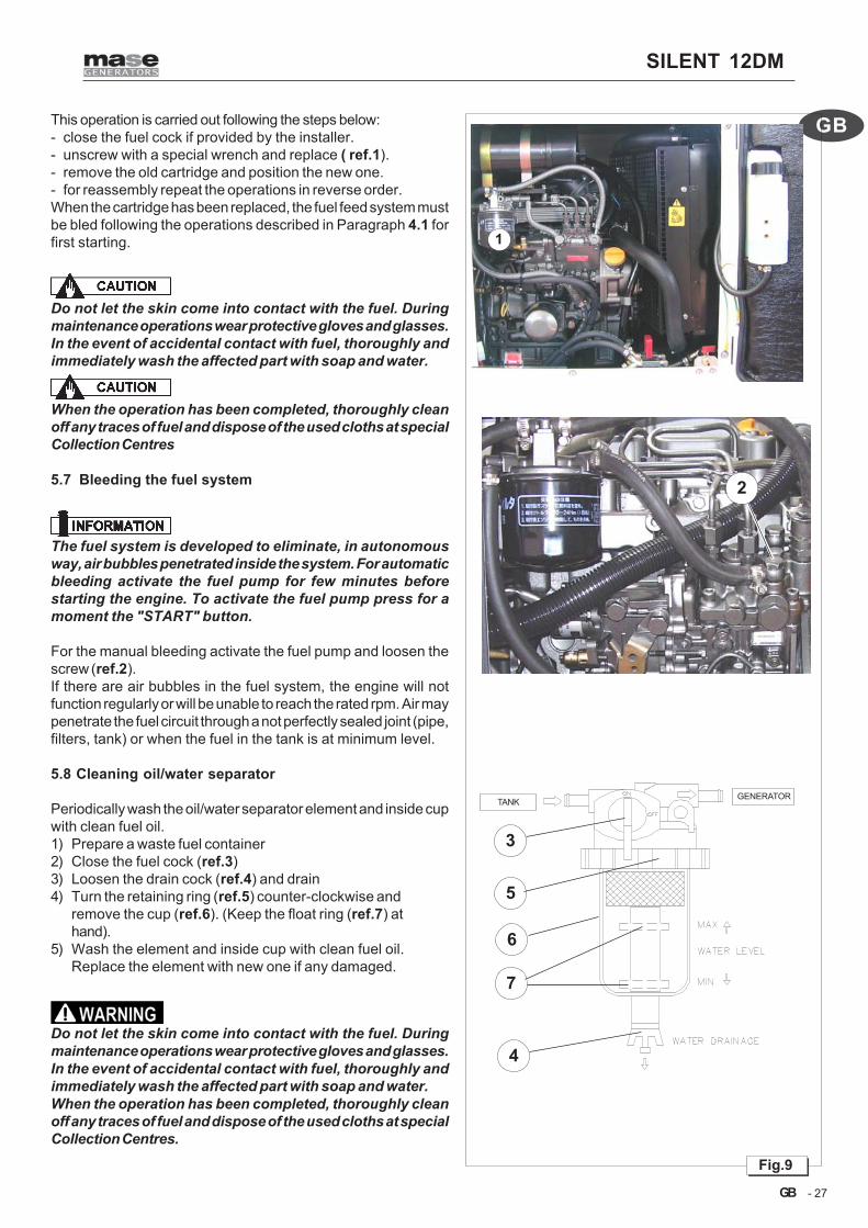
This operation is carried out following the steps below:- close the fuel cock if provided by the installer.- unscrew with a special wrench and replace ( ref.1).- remove the old cartridge and position the new one.- for reassembly repeat the operations in reverse order.When the cartridge has been replaced, the fuel feed system mustbe bled following the operations described in Paragraph 4.1 forfirst starting.
Do not let the skin come into contact with the fuel. Duringmaintenance operations wear protective gloves and glasses.In the event of accidental contact with fuel, thoroughly andimmediately wash the affected part with soap and water.
When the operation has been completed, thoroughly cleanoff any traces of fuel and dispose of the used cloths at specialCollection Centres
5.7 Bleeding the fuel system
The fuel system is developed to eliminate, in autonomousway, air bubbles penetrated inside the system. For automaticbleeding activate the fuel pump for few minutes beforestarting the engine. To activate the fuel pump press for amoment the "START" button.
For the manual bleeding activate the fuel pump and loosen thescrew (ref.2).If there are air bubbles in the fuel system, the engine will notfunction regularly or will be unable to reach the rated rpm. Air maypenetrate the fuel circuit through a not perfectly sealed joint (pipe,filters, tank) or when the fuel in the tank is at minimum level.
5.8 Cleaning oil/water separator
Periodically wash the oil/water separator element and inside cupwith clean fuel oil.1) Prepare a waste fuel container2) Close the fuel cock (ref.3)3) Loosen the drain cock (ref.4) and drain4) Turn the retaining ring (ref.5) counter-clockwise and
remove the cup (ref.6). (Keep the float ring (ref.7) athand).
5) Wash the element and inside cup with clean fuel oil.Replace the element with new one if any damaged.
Do not let the skin come into contact with the fuel. Duringmaintenance operations wear protective gloves and glasses.In the event of accidental contact with fuel, thoroughly andimmediately wash the affected part with soap and water.When the operation has been completed, thoroughly cleanoff any traces of fuel and dispose of the used cloths at specialCollection Centres.
TANK GENERATOR

SILENT 12DM
- 28
GB
GB
3 2
1
4
5
5.9 Electric Pump
The electric pump is equipped with a protective filter(ref.1).
The electric pump is cooled and lubricated with thefuel. Do not activate the pump without fuelin order to not damage it.
The feeding system has been developed for blow out,in autonomous way, the air beads penetrated insidethe system. Activate the fuel pump for few minutesbefore starting the generator to have automaticbleeding.To activate the fuel pump press the "START" buttonfor a moment.
5.10 Checking the V-belt tension
The belt is used to transmit the rotary motion from thepulley of the drive shaft to that of the closed-circuit fluidpump and the battery charger DC alternator (ref. 2).Adjust the belt tension as follows:loosen the adjusting screw (ref.3)and move the batterycharger DC alternator (ref.2)outwards to increase thetension and inwards to decrease it.The belt tension is right when it allows, under a thrustforce of 8 kg, a yield of about 10 mm.
To prevent the belt from idling, do not spill any oil onit. Clean the belt with petrol if it has oil on it.
Keep the hands away from the V-belt and the pulleysonce the engine has started.
5.11 Coolant check
Check the coolant with the engine off and cold.Each time the generator is used check the coolant levelwhich must be at about 2/3 above the height of the cuplocated above the radiator (ref.4), which functions asexpansion tank. When the level in the radiant block goesdown notably, top up bearing in mind that overfilling the cupmay cause a quite normal outflow of excess water from thedrain pipe during operation.
Never open the cover of the radiator(ref.5) and of the expansion vase when the engine ishot to avoid dangerous spillages of coolant.

SILENT 12DM
- 29
GB
GB
1
2
5.12Coolant replace
Replace the coolant every year inside the closed circuitof cooling.To change used coolant, first drain the system throughthe tap (ref.1).When the operation has been completed, close the tap.Now pour new coolant into the circuit through the radiatorcap (ref.2).
Dispose of the used refrigerant liquid in an appropriatemanner, since it is a polluting product.Take the used refrigerant liquid to special collectioncentres for disposal.
5.13Alternator maintenance
The alternator used on this model is the synchronous,self-excited type with electronic voltage control. Thismodel alternator, without manifold and brushes, does notrequire particular maintenance operations. The checksand periodic maintenance is limited to removing anytraces of damp and oxidation which might damage it.
5.14Battery maintenance
The generator is supplied with a battery without acid .
Have the battery activated by staffprepared with sulphuric acid for batteries and theappropriate tools.
Battery fluid is a corrosive acid,extremely harmful to the skin.Always wear protective gloves and be extremelycareful to avoid spillage when pouring the acid.
- Do not disconnect the battery when the generator isrunning; the battery charger alternator and theelectronic equipment may irreparably be damaged.
- Respect + / - polarity when connecting; failing thiswill cause a short-circuit when starting, which willirremediably damage the electronic equipment.
Do not cause short-circuits byplacing keys or tools on the batteries or on the cablefittings.
The terminals and the connectionsmust always be maintained dry and clean; to preventoxidation, clean and smear the terminals with a filmof vaseline.

SILENT 12DM
- 30
GB
GB Fig.10
4
1
5
2
6 ANOMALIES, CAUSES AND REMEDIES
6.1 Breakdown table
The starter motor turns but the main engine does not start- Check that there is fuel in the tank. (Fill up)- Check that the stop solenoid valve is powered. (Consult
Service Centre) (fig.10,ref.1)- Check fuel pump functioning. (Consult Service Centre)- Perform operations of drainage from air beads inside the fluel
circuit (see par. 4.1)
BE is not activated- Check if the thermal interrupter (fig.10,ref.2) of protection is
open. (To restore the contact press on the button).- Check the cables and the clamps of connection to the
battery and the electric connections. (Reconnect).- Check the integrity of the battery. (Recharge or Replace).- Turn the switch (fig.10,ref.5) on 1 (ON).
The generator switches off during the operating period• Check if a protection has been activated with the lighting of
the relative warning light. (Remove the cause and retry thestarting)
• Check if there is fuel in the tank. (Fill up).
There is high smoke emission from the exhaust.• Check the air filter. (Clean its elements or, if necessary,
replace them).• Check that the oil level does not exceed the MAX notch.
(Bring it down to the correct level).• Check the generator group is not overloaded.• Check the setting of the injectors. (Consult Service Centre).
The engine runs irregularly• Check the fuel filter (fig.10,ref.4). (Replace it)• Check the air filter. (Clean its elements or, if necessary,
replace them).• Perform operations of drainage from air beads inside the fluel
circuit (see par.4.1)
The tension of the alternator is too much low. • Correct the value of the tension acting on the electronic
regulator.• Check the rpms of the engine (1560 rpms without connected
loads).• Regulator of tension damaged (Replace).
Starter battery flat. • Check the electrolyte level in the battery. (Fill up).• Check the battery charging device. (Replace).• Check integrity of the battery.
The generator does not deliver power to the outlets.• Check that the differential magnetothermal switch, or a
magnetothermal switch, is in the ON position. (ConsultService Centre).
When the power fails the generator DOES NOT start.• Check that the automatic control unit is in “automatic” mode.Set “AUTO”.• Check if there is an alarm in the automatic control unitmemory. Reset and select “AUTO”.• Check that the automatic control unit is on. Call the ServiceCentre.• Check the generator. Consult Service Centre.
When the power is restored the generator DOES NOT turnoff.• Check that the power has actually been restored.• Wait for the generator to cool down. Consult Service Centre.
No power delivered to the utilities.• Check that there is mains power.• Check that the automatic control unit is in “AUTO” OPERATING
MODE. Set to “AUTO” MODE.• Check that the automatic control panel is intact. ConsultService Centre.• Check the connections. Consult Service Centre.• Check that the mains/generator/utility line switches areenergised. Set the main switches to position 1.
5.15 Long period of inactivity
If the generator is not to be used for long time, do thefollowing operations.• Change the engine oil.• Clean the air filter.• Disconnect the battery cables. We recommend you
recharge the battery every month in order to prevent itfrom going completely flat which, sometimes,compromises its integrity.
• Clean the outside of the generator, removing all dust andimpurities.

SILENT 12DM
- 31
GB
GB
100K
ohm
3 3 455 6 5 7560
HZ
SR7A.V.R.
1
26
7. WIRING DIAGRAM
1AL
TER
NAT
OR
2BA
TTER
Y C
HAR
GER
ALT
ERN
ATO
R3
DIO
DE
4ST
OP
ELEC
TRO
MAG
NET
5FU
SE6
RE
SE
RV
E F
LOA
T7
PILO
T LI
GH
T8
STAR
TER
MO
TOR
9S
OC
KE
T 3P
+N+G
ND
32A
10S
OC
KE
T 3P
+N+G
ND
32A
11O
IL P
RE
SS
UR
E S
WIT
CH
12EM
ERG
ENC
Y ST
OP
BUTT
ON
13M
AGN
ETO
THER
MAL
SW
ITC
H 2P
14M
AGN
ETO
THER
MAL
SW
ITC
H 2P
15M
AGN
ETO
THER
MAL
SW
ITC
H 2P
16G
RO
UN
D C
ON
NEC
TIO
N17
TIM
ER U
NIT
18R
ELAY
1915
PO
LES
CO
NN
ECTO
R20
BATT
ERYS
WIT
CH
2116
PO
LES
CO
NN
ECTO
R22
ENG
INE
HEA
TIN
G23
ELEC
TRO
NIC
VO
LTAG
ER
EGU
LATO
R
24ST
ART
REL
AY25
STO
P R
ELA
Y26
ROTO
R27
ENG
INE
HEA
TER
28ST
ATO
R29
THER
MAL
SW
ITC
H30
ENG
INE
THER
MO
STAT
31BA
TTER
Y32
PREH
EATI
NG
33R
ELAY
34AL
TER
NAT
OR
TER
MIN
AL B
OAR
D35
FUE
L LE
VE
L S
EN
SO
R
SILENT 12DM
- 32
GB
GB
Fig.13
8. TRANSPORT, STORAGE, LIFTING ANDHANDLING
8.1 Transport and storage
Transport: During transport the generator (with orwithout packaging) must be protected againstatmospheric agents, it must not be turned upside downand must be protected against knocks.
Packaging: Supplied directly by Mase Generators.The total weight of the packed generator is given inParagraph 2.4 “Table of technical characteristics”.It is strictly prohibited to pollute the environmentwith the packaging.
Storage: The generator must be stored in horizontalposition and away from atmospheric agents and humidity.
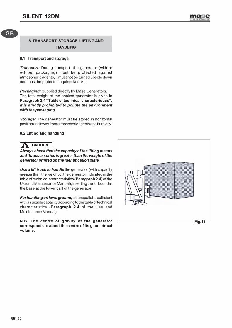
8.2 Lifting and handling
Always check that the capacity of the lifting meansand its accessories is greater than the weight of thegenerator printed on the identification plate.
Use a lift truck to handle the generator (with capacitygreater than the weight of the generator indicated in thetable of technical characteristics (Paragraph 2.4) of theUse and Maintenance Manual), inserting the forks underthe base at the lower part of the generator.
For handling on level ground, a transpallet is sufficientwith a suitable capacity according to the table of technicalcharacteristics (Paragraph 2.4 of the Use andMaintenance Manual).
N.B. The centre of gravity of the generatorcorresponds to about the centre of its geometricalvolume.

SILENT 12DM
- 33
GB
GB
9 GUARANTEE AND RESPONSIBILITY
9.1 Guarantee
• The MASE generators and all their components areguaranteed free of defects and are covered by theguarantee for a period as required by current legislationfrom the date of installation.
• Not covered by the guarantee are: failed observance ofthe installation regulations, damage caused by naturaldisasters, accidents, defects of the electrical systemincluding the load to which the generator is connected,negligence, improper use or abuse by the operator anddamage caused by repairs carried out by unqualifiedpersonnel.
• Repairs that cannot be carried out at the place ofinstallation can be carried out at MASE laboratories orat authorised workshops. Transport expenses will beborne by the Customer.
• Under no circumstances does the Customer have theright to claim compensation for damages or sideeffects caused by use of the machine in a manner notconform to what is described in this manual.
9.2 Limits of responsibility
MASE GENERATORS S.p.A is responsible for anythingregarding the safety, reliability and performance of theGenerator on the condition that:
• The generator is used by persons trained through theuse and maintenance manual.
• The installation is carried out according to MASEinstructions.
• The service procedures are carried out exclusively byMASE specialised technical personnel.
• The electrical system and the loads to which thegenerator is connected is in conformity with theapplicable CEI regulations.
• The Generator is installed and used in accordance withthe installations provided in this manual.
• Use original spare parts specific to each model.
• Use suitable fuel.Diesel fuel conforming to standards ASTM A975.
10. DISPOSAL
10.1Disposal of the waste materials deriving frommaintenance and scrapping
• The packaging used for transport is biodegradable andthus easy to dispose of by companies authorised forpaper collection.
• The batteries must be disposed of according to theregulations regarding toxic and noxious waste.
• The engine oil and engine oil filters, both after an oilchange and when scrapping, must be taken tocompanies authorised for this collection.
• The electrical components must be taken to companiesauthorised for the collection of electronic material.
• All the painted metal parts must be taken to companiesauthorised for the collection of metals.
• Any other material not listed above must be taken tocompanies authorised for the collection of industrialwaste.