Embed Size (px)
Citation preview

PORTER Reliant
1
PORTER
Reliant Water Steam Sterilizer
User Manual
40HD
Rev. 0 Date : January 2009
FM-1364 Rev. –

PORTER Reliant
2
This sterilizer fulfils all the directions in force concerning the safety, and the built-in parameters has been properly set by the manufacturer in order to warranty effective sterilization if proper loading conditions are fol-lowed.
Please, read carefully this manual before using the machine; an improper utilization of the sterilizer should carry on defective sterilization with unattended consequences.
In case of doubt or questions, please call the agent.
Thanks for the confidence given.
All rights reserved
No portion of this publication can be printed, transmitted, rewritten, stored in a data recovery system,
translated in any foreign or computer language, in any form or through any devices, without written
consent by Porter .
Information in this manual is subject to change without any warning or prior notice by Porter and does not represent a commitment for the vendor.
Reliant is a trademark of PORTER.
ATOMA PLUS is trademark of Dental X.
STERILINE is a trademark of Dental X.
DENTAL X s.r.l. Via Marzotto 11 36031 Dueville (VI) Italy Tel. +39 0444 367400 Fax +39 0444 367436 e-mail: [email protected] http://www.dentalx.it
© Dental X 2009

PORTER Reliant
3
TABLE OF CONTENTS
1. GENERAL ..................................................................................................................................................... 4 1.1 INTRODUCTION .................................................................................................................................. 4 1.2 CONFORMITY TO EUROPEAN DIRECTIVES ..................................................................................... 4
2. FAMILIARIZATION ....................................................................................................................................... 5 2.1 PACKAGE DIMENSIONS AND WEIGHT ............................................................................................. 5 2.2 UNPACKAGING ................................................................................................................................... 5 2.3 OVERALL DIMENSIONS ...................................................................................................................... 6 2.4 USABLE SPACE IN THE CHAMBER ................................................................................................... 6 2.5 SAFETY FEATURES ............................................................................................................................ 7 2.6 PRECAUTIONS .................................................................................................................................... 8 2.7 FRONT AND REAR VIEW .................................................................................................................... 9 2.8 STANDARD ACCESSORIES ............................................................................................................. 10 2.9 TECHNICAL SPECIFICATIONS ......................................................................................................... 10
2.9.1 Environment operating conditions ..................................................................................... 10 3. INSTALLATION .......................................................................................................................................... 11
3.1 BASIC REQUIREMENTS ................................................................................................................... 11 3.2 GETTING STARTED .......................................................................................................................... 12 3.3 NOTES ON ALTITUDE COMPENSATION ......................................................................................... 13
4. OPERATING INSTRUCTIONS ................................................................................................................... 14 4.1 FRONT PANEL COMMAND/SIGNALING ........................................................................................... 14 4.2 SELECTING A STERILIZAZION CYCLE ............................................................................................ 15
4.2.1 The available sterilization cycles ....................................................................................... 15 4.2.2 Starting a sterilization cycle ............................................................................................... 16
4.3 STOPPING THE CYCLE .................................................................................................................... 17 4.4 TOPPING UP AND DRAINING THE TANKS ...................................................................................... 18
4.4.1 Topping up the main tank .................................................................................................. 18 4.4.2 Draining the tanks ............................................................................................................. 18
5. PROGRAMMING ........................................................................................................................................ 19 5.1 DATE AND TIME ................................................................................................................................ 19 5.2 MEASUREMENT UNITS AND OPTIONS ........................................................................................... 19 5.3 SPECIAL CYCLE ................................................................................................................................ 20
6. MAINTENANCE .......................................................................................................................................... 21 6.1 AUTOMATIC PERIODIC CLEANING CYCLE .................................................................................... 21 6.2 CLEANING THE INSTRUMENTS BEFORE THE STERILIZATION ................................................... 22 6.3 CLEANING/REPLACING THE WATER FILTER ................................................................................ 22 6.4 REGULAR STERILITY TESTS ........................................................................................................... 22
7. TROUBLESHOOTING ................................................................................................................................ 23 7.1 MANUAL DIAGNOSIS ........................................................................................................................ 23 7.2 AUTO-TEST AT THE SWITCHING ON .............................................................................................. 24
8. ALARMS ..................................................................................................................................................... 25 8.1 GENERAL ........................................................................................................................................... 25 8.2 WARNING MESSAGES ..................................................................................................................... 25 8.3 PRE-WARNING ALARMS .................................................................................................................. 25 8.4 ABORTED CYCLE ALARMS .............................................................................................................. 26
9. CONNECTIONS .......................................................................................................................................... 27 9.1 CONNECTION TO AN EXTERNAL PRINTER.................................................................................... 27 9.2 CONNECTION TO A COMPUTER (ONLY FOR SERVICE) ............................................................... 28
APPENDIX: SERVICE BOOK

PORTER Reliant
4
1. GENERAL
1.1 INTRODUCTION
Object of this manual is to supply instructions for the operators in order to allow:
correct installation
right use
proper maintenance of the sterilizer
The machine must be installed and operated according to the procedures described in this manual.
The user is responsible for what concerns the fulfilment in the legal subject concerning installation and operation of the sterilizer.
If the machine is not correctly installed and operated or the appropriate maintenance is not carried out, the manufacturer cannot be considered responsible for any possible breaks and malfunctions.
Please, check for the packing integrity and no evident damages or missing parts (see delivery note).
IN CASE OF DAMAGES OR MISSING PARTS, PLEASE IMMEDIATELY INFORM AND IN DETAIL
THE FORWARDER, PORTER AND ITS AREA AGENT’.
1.2 CONFORMITY TO EUROPEAN DIRECTIVES
The sterilizer complies with the electromagnetic compatibility standards in conformity with the Medical De-vice Directive 93/42/CEE and with the norm EN 13060.
This equipment has been developed and manufactured using high quality material and parts that can be recycled and reused.
This symbol means that electrical and electronic equipment, at the end of their lifetime, must be disposed separately from the household waste. Dispose this unit by carrying it to the local collection/disposal centre. Sanctions are applied in case the regulations concern-ing waste disposal are not met.
Help us to preserve the environment in which we live !

PORTER Reliant
5
2. FAMILIARIZATION
2.1 PACKAGE DIMENSIONS AND WEIGHT
Total weight: 61 Kg
Store the package for possible future shipment.
2.2 UNPACKAGING

PORTER Reliant
6
2.3 OVERALL DIMENSIONS
Net weight 49 Kg
Full load weight 61 Kg
2.4 USABLE SPACE IN THE CHAMBER
Diameter: 240 mm Depth 384 mm Capacity 17,5 l
Useful dimensions per tray: 315 x 214 mm (x2), 315 x 168 mm (x2) Useful tray volume: 10 l
PORTER Reliant
7
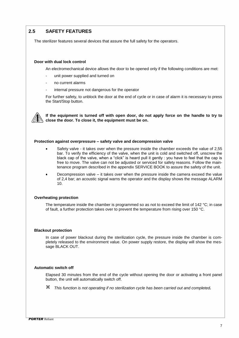
2.5 SAFETY FEATURES
The sterilizer features several devices that assure the full safety for the operators.
Door with dual lock control
An electromechanical device allows the door to be opened only if the following conditions are met:
- unit power supplied and turned on
- no current alarms
- internal pressure not dangerous for the operator
For further safety, to unblock the door at the end of cycle or in case of alarm it is necessary to press the Start/Stop button.
If the equipment is turned off with open door, do not apply force on the handle to try to
close the door. To close it, the equipment must be on.
Protection against overpressure – safety valve and decompression valve
Safety valve - it takes over when the pressure inside the chamber exceeds the value of 2,55 bar. To verify the efficiency of the valve, when the unit is cold and switched off, unscrew the black cap of the valve, when a “click” is heard pull it gently : you have to feel that the cap is free to move. The valve can not be adjusted or serviced for safety reasons. Follow the main-tenance program described in the appendix SERVICE BOOK to assure the safety of the unit.
Decompression valve – it takes over when the pressure inside the camera exceed the value of 2,4 bar; an acoustic signal warns the operator and the display shows the message ALARM 10.
Overheating protection
The temperature inside the chamber is programmed so as not to exceed the limit of 142 °C; in case of fault, a further protection takes over to prevent the temperature from rising over 150 °C.
Blackout protection
In case of power blackout during the sterilization cycle, the pressure inside the chamber is com-pletely released to the environment value. On power supply restore, the display will show the mes-sage BLACK OUT.
Automatic switch off
Elapsed 30 minutes from the end of the cycle without opening the door or activating a front panel button, the unit will automatically switch off.
This function is not operating if no sterilization cycle has been carried out and completed.

PORTER Reliant
8
2.6 PRECAUTIONS
The international norms concerning safety and sterilization process defines the following figures:
OPERATOR: the person operating the unit to achieve the expected result.
RESPONSIBLE AUTHORITY: person or group responsible for the use and maintenance of the unit, he or she also has to make sure that:
- all personnel who operate or maintain the equipment are trained in its operation and in its safe use
- there is regular training of all personnel concerned with the operation and maintenance of the equipment, includ-ing emergency procedures for any toxic, flammable, explosive or pathogenic material released into the environ-ment.
- Records of attendance at training are maintained, and evidence of understanding demonstrated.
The purpose of this manual is to provide suitable use instructions for both figures: however it does not give instruc-tions concerning the STERILIZATION PROCEDURE and the cautions to be followed to prevent contamination of in-struments and/or personnel using the unit that is a assignment of the RESPONSIBLE AUTHORITY of the practice.
We wish to point out the following risks:
- The sterilization is a process that works by means of water steam under pressure and high temperatures; when the load is removed from the sterilization chamber always use tools and wear personal protections suitable for handling hot instruments.
- On opening the sterilizer, especially in case the cycle has been aborted, a small quantity of hot water steam or condensate can be released in the environment; be careful when opening the door.
- If the condensation cycle is not brought to an end, the load, the trays and the tray support as well as the cham-ber inner space are ALWAYS to be considered as potentially contaminating elements, as long as a subsequent sterilization cycle has not been successfully completed.
- The water contained in the recovery tank is to be regarded as biologically contaminating, therefore when this tank is emptied, suitable precautions should be taken. The disposal of recovery water needs to be done in ac-cordance with the national or local regulation. Check the integrity of the draining pipe before its use.
- To prevent cross contaminations during the loading and unloading steps, open the door with clean hands or wear uncontaminated gloves to avoid contaminating the door handle, do not use gloves worn during the in-struments decontamination step for this operation; when the sterilized instruments are removed from the chamber, always use uncontaminated gloves.
- In case of contact with hot water, steam or contaminated materials rinse with fresh water and seek for medical help
SYMBOLS
On the panels of the unit and in this manual, potential hazards and the parts that can be dangerous at high tempera-tures, are marked with this symbol:
WARNING: instruments and chamber are very hot
Contamination risk
CAUTION, risk of danger
Documentation needs to be consulted
Read carefully this user manual because wrong use may expose the user to health risks.
This symbol indicates the presence of additional important notes about the use
The water steam sterilizer is designed to be used for the sterilization of reusable medical instruments that can be steam sterilized in a range of temperatures between 121°C and 135°C; any attempt of sterilizing instruments that are not fit for undergoing this process can result in hazard for the operator: it can also lead to potentially serious faults and damage the sterilizer’s safety mechanisms.
The unit is not to be used to sterilize liquids and flammable materials.

PORTER Reliant
9
The unit is designed for indoor use only.
Do not use in presence of anaesthetic or flammable gas.
To avoid an excessive level of humidity, properly air the room where the unit is installed.
2.7 FRONT AND REAR VIEW
Door
Door handle
Control panel
Distilled water recervoir filling point
Bacterial filter
Door gasket
Quick connector for distilled water tank drain
Water inlet filter
Water outflow filter
Chamber water inlet
Temperature sensor
Air line filter
Safety valve connection
Air grid and cooling fan
Safety valve
Power supply switch
Power supply cord
Printer connector (option)
Main fuses
Quick connector for used water tank drain
Automatic draining of used water tank (option):
max flow 20 ml/minute, water T < 70°C

PORTER Reliant
10
2.8 STANDARD ACCESSORIES
To make the warranty active it is necessary that a copy of the supplied Unit Passport is sent, through the agent, to the manufacturer; for want of this the warranty will decline.
2.9 TECHNICAL SPECIFICATIONS
Chamber dimensions Ø = 240 mm Depth = 384 mm
Auto-switching-off elapsed 30’ from the end of a cycle and without any action
Chamber capacity 17,5 l
Dual water tank 3,5 liters each (used and clean water tanks)
Maximum load 4 kg (solid) 1,5 kg (porous)
Bacterial filter 0.3 µm al 99.97 %
Warming-up time 20’ from room temperature 10’ with pre-heated chamber
Clock battery
(may be replaced only by au-thorized service)
Varta CR2032
Sterilization time from 3’ to 90’ depending on the selected cycle
Transmitted heat
in environment 0,18 J/h at 23°C
Drying time from 6’ to 30’ depending on the selected cycle
Sound emission 61 dB/A at 1 m
External dimensions 443 x 570 x 428 mm (L x D x H)
Working cycle continuous
Net weight 49 Kg Pollution grade 2
Power supply voltage 120V +/-10% Transient overvoltage II
Frequency 60Hz
Max consumption 1500 W Maximum volume available
on the trays 10 l
Average consumption 600 W Maximum chamber
temperature 135°C (-0/+2°C)
Standby consumption 1 W Safety valve
working pressure 2,55 bar
AC Fuses 2 x 15AT 250V (type 6.3x32 ) UL listed
2.9.1 Environment operating conditions
The sterilizer is designed to operate in environments at temperatures between 3 °C and 40 °C, relative humidity not greater than 95%, atmospheric pressure from 750 mBar to 1050 mBar and altitude between 0 and +2500 meters.
NEVER USE IN PRESENCE OF INFLAMMABILE ANAESTHETIC GAS

PORTER Reliant
11
3. INSTALLATION
3.1 BASIC REQUIREMENTS
1. Check that the mains voltage of your electrical installation matches the value indicated on the equipment plate, the electrical socket is capable to supply at least 15A and is provided with an efficient earth connec-tion. In case the installation makes inaccessible the power supply switch, provide for a proper electrical breaker.
The manufacturer will not be responsible for damages to people
or things caused by an unsuitable electrical installation or miss-
ing of the ground connection.
2. The equipment must be installed on a flat surface; adjust the front feet to have a slight slope and so make the out-flow of water easier during the drain phase.
WARNING: do not place the unit on surfaces which could cause fire or fume if hot items fall from the equipment
3. For the correct operation, it is mandatory to leave a free space of at least 4 cm on the rear side of the equipment.
4. Do not install the equipment near heat sources, in humid or not well aired environment; in a sterilization room is re-quired a minimum of 10 air changes per hour, a recirculat-ing ventilation system can not be used.
5. On the rear panel it is located the safety valve, if it oper-ates for overpressure it may be released hot steam: locate the unit to eliminate the risk of burning for the operator (f.e. near a wall)
The sterilizer can also be installed in a cabinet. In this case, provide adequate space (>10 cm) for aeration.
>4cm
120Vac 60Hz I> or = 15A

PORTER Reliant
12
3.2 GETTING STARTED
These operations should be carried out only by qualified personnel, wrong settings could
affect the quality of the sterilization.
Check the electrical requirements and connect the power supply cable to the mains socket.
1. The equipment is delivered with empty tank and is therefore necessary to fill it completely with demineralized water. Fill the tank without exceeding the maximum level reference marked on the tank opening.
The use of low quality demineralized water could create scale deposits on the instruments, inside the chamber and on the trays. Carefully read the label of the demineralized water con-tainer. Do not use tap water even if treated with filters or sweet-eners.
Do not use water for batteries, other liquids or additives
which can cause irreversible damage to the equipment and
be a risk for the operator.
2. Turn on the equipment with the main switch on the back panel. This switch can be left ON since the electrical consumption in stand-by is almost nil.
3. Remove the basket and the trays from the chamber and close the door.
When the unit is off, the door is blocked; if the block persists, turn off and then on again the unit.
4. Hold on the key and push the key
Power; the display
shows the message <SET ALT 100 MT> with the set altitude value (100 m).
Use both keys to adjust the value as necessary according to the actual site altitude (see next page).
Then push the key Set to confirm the displayed value and start
the automatic initialization procedure with the entry of water in the hydraulic circuit and chamber.
to increase the value,
or
to decrease the value

PORTER Reliant
13
5. At the end of the initialization procedure the Led READY turns on; open the door and dry the chamber with a clean cloth.
In case of procedure steps not correctly followed, the display will show one of the following warning messages:
DOOR OPEN: door not closed
ADD H2O: lack of water
NEED INST: initialization procedure not carried out.
In this case, repeat the procedure.
With procedure already been performed, the display will show
OFF and the door stays blocked. To unblock it, push the key Power.
The sterilizer is ready for use. Arrange basket and trays in the chamber and select the sterilization cycle.
See Chapter 4 «OPERATING INSTRUCTIONS».
3.3 NOTES ON ALTITUDE COMPENSATION
For a proper operation of the pressure control devices, an altitude compensation feature has been intro-duced.
During the installation procedure it is necessary to set the altitude value (referred to sea level) for the site where the unit operates. This procedure must be carried out every time the unit is moved to a site with dif-ferent altitude from the one previously set.
During the factory test the equipment is set at a default value of 100 meters and can be left unchanged for real altitude values between 0 and 200 meters, since a ±100 meter error does not affect the equipment operation.
To be sure of the sterilization process, it is important that the altitude tolerance from the current value does not exceed 200 meters; otherwise, the vacuum devices should be additional loaded, and false or premature AL8 or AL5 alarm should be signalled.
CONVERSION NOTE: to obtain meters multiply feet by 0.3048
These operations should be carried out by qualified personnel. Wrong settings can affect the quality
of the sterilization.

PORTER Reliant
14
4. OPERATING INSTRUCTIONS
4.1 FRONT PANEL COMMAND/SIGNALING
The front panel is equipped with control keys, signalling Led’s and displays. A slight push on a key will activate the command.
LCD Displays: Visualize (from the top) the value of the para-
meters Time (Led Time turned on), Temperature (measure unit: °C or °F, depending on the setting, related Led turned on)
and Pressure (measure unit: bar or psi, depending on the set-ting, related Led turned on); the upper display visualize, instead
of time, the alarms occurred during the cycle (Led Alarm turned on).
Phase in progress indication: HEATING – STERILIZE – DRY – READY - turned on or flashing during the phases of the cy-cle.
Tank water level indication: Turned on for water level in the main tank and used water tank at minimum or maximum value respectively.
Current program indication: 1 – 2 – 3 – 4 - turned on for the selected program.
PRINTER indication: turned on for printer enabled.
Program selection keys :
Program 1 – Sterilization at °C, 4 min. : for unwrapped solid instruments
Program 2 – Sterilization at 134°C, 20 min. : for hollow and porous material (also wrapped)
Program 3 – Sterilization at 121°C, 30 min. : for delicate hollow and porous material (also wrapped) not supporting high temperature
Program 4 - Special cycle programmable by the op-erator
Key Start/Stop: controls the start or the stop of the selected cycle, unlocks the door at the end of the
cycle or in case of alarm occurred during the cycle.
Key Power: enables the command panel, the auto-test at the switching on and the pre-heating resis-
tance.
Key Set: allows to set: date/time, measuring units, report printout language, sterilization Tem-
perature/Time and drain time for the special cycle.
Key Printer: enables the report printout. The key has own indication Led: for Led off, the PC port can
be used for the PC connection (Service mode only).
PORTER Reliant
15
4.2 SELECTING A STERILIZAZION CYCLE
1. Turn on the equipment by means of the rear switch.
display TIME is showing the current time
display TEMP. is showing OFF
display PRESS is showing the current day and month
2. Push the key Power and wait for a few seconds the initial auto-test completion; during this time
the parameter set-points and the type of the components currently tested will appear in a sequence
on the display. Over the auto-test, the display TIME will show again the current time, the display
PRESSURE the value of the current pressure, the display TEMPERATURE the value of the current
chamber temperature (if lower than 35 °C the display will show the message “low”). The micro-processor enables the pre-heating step in order to rise the chamber temperature up to 100 °C.
During this phase the temperature reading on the display is inaccurate, because no steam being
there.
3. Arrange the material to be sterilized on the trays, load the chamber and close the door.
4. Check that Led MIN (main tank indication) is off. If not, fill up the main tank with demineralized wa-ter without exceeding the maximum level reference marked on the tank opening.
4.2.1 The available sterilization cycles
Key Program Parameters Load type Maximum load Check test Cycle type
unwrapped
134°C / 4 min drying 6 min.
134-137°C
2.14-2.30 bar Unwrapped solid instruments
4 kg solid
Unwrapped solid load
EN13060 par. 10.5
N
wrapped
134°C / 20 min drying 20 min.
134-137°C
2.14-2.30 bar
Solid, porous, hollow type B and wrapped instru-ments (ref. EN868)
4 kg solid or 1,5 kg porous or a proportion combi-nation of both
Porous load
EN13060 par. 10.9 S
packs
121°C 30 min drying 20 min.
121-124°C
1.10-1.30 bar
Solid, porous, hollow type B and wrapped instru-ments (ref. EN868)
4 kg solid or 1,5 kg porous or a proportion combi-nation of both
Porous load
EN13060 par 10.9 S
special
Values set by the operator 105 – 135°C 3 – 90 min drying = 5, 10, 20 or 30 min
105-137°C 0.28-2.30 bar
Depends on the set parameters
Depends on the set parameters
To be defined by the operator
Depends on the set para-
meters
To select the program push the relating key.
The indication Led of the selected program turns on, and the displays will show for 5 seconds the parameters of the cycle currently selected.

PORTER Reliant
16
4.2.2 Starting a sterilization cycle
Press the key START/STOP to start the selected cycle.
The door is locked and stays locked throughout the cycle duration.
The parameters of the selected cycle are shown once again for 10 seconds, then the sterilizer starts and runs the cycle phases automatically. The various steps of the cycle are microprocessor controlled and se-quentially shown on the display; in this way the operator can monitor the progress of the sterilization phases and the times. The signalling for the various phases of the cycle are reported on the following:
Led heating turns on
Display Time starts to record the cycle duration
Display Pressure shows the chamber pressure value
Display Temperature shows the chamber temperature value
he program indication Led (1, 2, 3 o 4) starts to flash.
Heating (water entry and heating)
During this first phase a water dose is entered into the chamber and the microprocessor enables the heating phase. Pump operation may be slightly noisy.
Sterilize
Reached the pre-set parameter values, Led HEATING turns off, and Led STERILIZE turns on. The display Time starts the countdown marking the time remaining to the end of the sterilization proc-ess, and the Pressure and Temperature displays show the pressure and temperature values of the steam.
The sterilization phase is followed by the decompression phase, with the display Pressure showing the decreasing pressure values down to 0. Again, the display Time will start the countdown of the decompression phase. Based on the our experiences, the decompression time has been slightly extended in order to minimize the thermal shock consequent to the status change of the steam.
Dry
Over the decompression phase, Led STERILIZE starts to flash to signal the completion of the ster-
ilization process. At the same time the Led DRY turns on, signalling the start of the drying phase. Throughout this phase, the chamber heaters keep the chamber warm according to a microproces-sor-controlled logic. The display TIME shows the countdown of this phase. Follows the forced venti-lation phase through the bacterial filter, the display Time shows also the countdown of this phase.
End of cycle
As soon as the drying is over, Led DRY turns off and Led READY and STERILIZE turn on. A 10-second alert signal is generated to draw the attention by the operator. The chamber heaters are set at reduced power (pre-heating) until the door is open. The TIME display shows the total time of the cycle, the displays TEMP. and PRESS show respectively the current temperature and pressure of the chamber.
At the end of the special cycle only Led READY will light (not Led STERILIZE) to signal that the efficiency of the cycle has not been tested by the manufacturer.
To unlock the door before opening it, press the key Start/Stop.
The cycle is over and the load can be taken out.
ATTENTION: instrument and chambers are very hot

PORTER Reliant
17
Opening the door, the displays will show again the current time, chamber temperature and pressure, and the sterilizer is ready for a new cycle.
If a printer is connected and ready, a report will be issued during the cycle phases with the more signifi-cant data; the report can be filed as proof of the sterilization process performed.
The operator can arrange other load on the trays and start a new sterilization cycle, with the advantage of
shorter heating-up time as the chamber is already warm, or press key Power to turn off the unit (stand-by).
If the door is not opened or a key pressed within 30 minutes, the unit switches to stand-by (OFF)
automatically.
Should any failure or error occur during the cycle, Led ALARM turns ON and the display Time will show alarm type and code (see chapter ALARM).
ATTENTION: instrument and chambers are very hot
Contamination risk
4.3 STOPPING THE CYCLE
To stop the sterilization cycle, press key Start/Stop. The display Time shows the message “MANU
STOP”.
Before opening the door, make sure that the display Pressure is showing the value 0. A safety device will anyway prevent from opening the door with the chamber over-pressurized. To unlock the door press key
Start/Stop.
Remove the load and check for the presence of water into the chamber. In case of wrapped instruments, we suggest to replace with new bags.
Before loading the chamber again, dry it carefully and wait 10 minutes to allow the water to evaporate and be drained completely.

PORTER Reliant
18
4.4 TOPPING UP AND DRAINING THE TANKS
The sterilizer is fitted with two 3,5-liters tanks; main tank for the clean demineralized water and recovery tank for used water . The hydraulic system allows the recovery of the steam generated during the sterilization process. The re-covery takes place during the decompression phase, and the steam is condensed and collected into the used water tank. As it is full, the exceeding water outflows into the main tank and recycled. This feature has been taken into account during the equipment design in order to avoid the risk of water pollution from the condensed steam; we recommend anyway to carry out periodically the complete drain of the tanks and the fill of the main tank with new demineralized water; soluble deposits on not-completely cleaned in-struments can indeed be transported by the steam into the tubes and deposit into the tank, on electro-valves, filters, internal chamber surface, trays and instrument itself causing on course of the time marks and sterilizer malfunction. After about 5-8 cycles the Led MIN turns on signaling the need for a main tank topping up; in case you de-cide to use the water one time only (not the recycled water), fill up the tank and carry out the drain of the used water tank. Otherwise the led Max will turn on signalling that the used water tank is full and the ex-ceeding water will be poured into the main tank.
4.4.1 Topping up the main tank
The lighting of the Led MIN signals a water level into the main tank insufficient to perform a new cycle.
Provides for the topping up of the main tank, taking care to not exceed the maximum level reference marked on the tank opening.
4.4.2 Draining the tanks
In case of operation with recycled water it is necessary, after about 60 cy-cles, to drain completely both tanks and fill the main tank with new deminer-alized water . In this case:
Get a bucket or a tank of at least 3,5 l capacity.
Fix the drain tube into the left fast fitting (black) and wait for a complete draining.
Unfit the tube pushing the ring nut against the machine and drawing the tube.
Repeat the operation for the main tank (right fast fitting - white).
Provides for the fill of the main tank with 3.5l of demineralized water, tak-ing care to not exceed the maximum level reference marked on the tank opening.
CAUTION! The water contained in the recovery tank is to be regarded as biologically contami-nating, therefore when this tank is emptied, suitable precautions should be taken. The disposal of re-covery water needs to be done in accordance with the national or local regulation.
Draining the used water tank
Draining the main tank
PORTER Reliant
19
5. PROGRAMMING
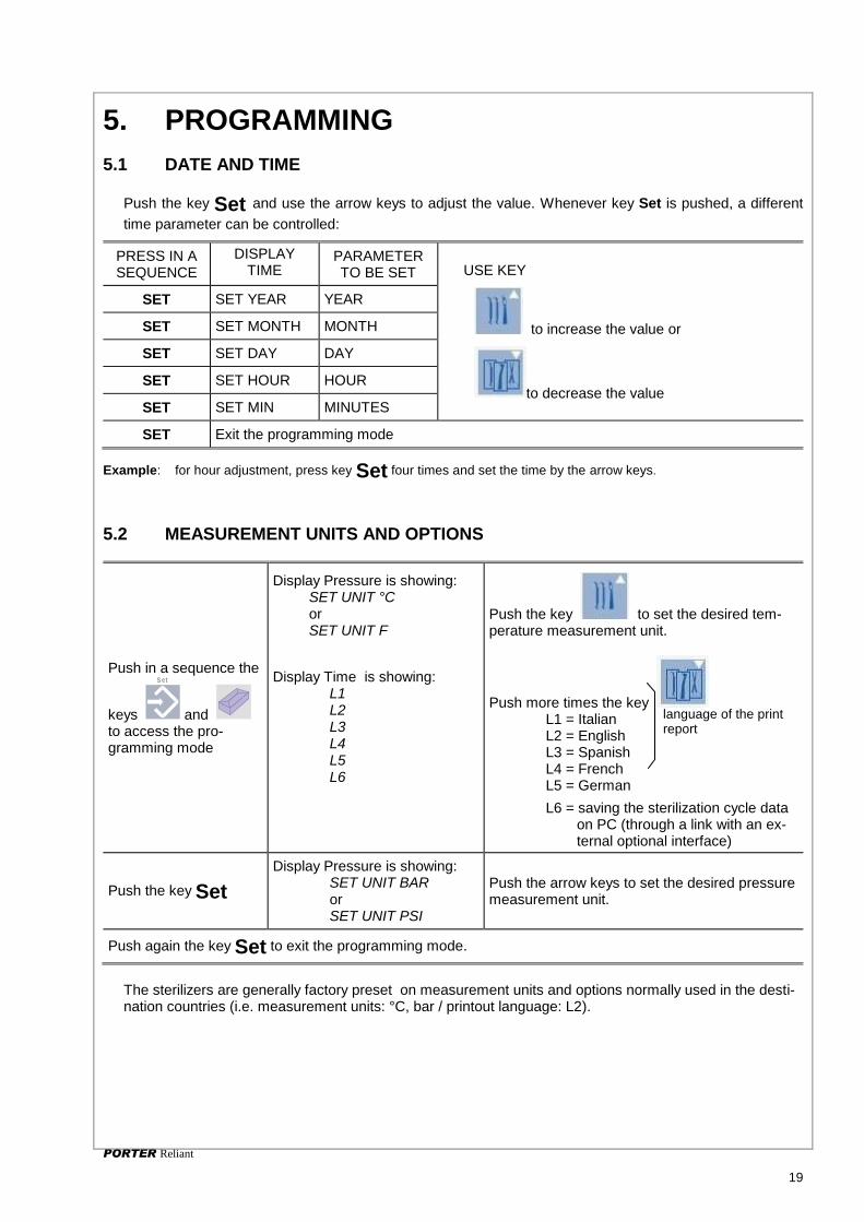
5.1 DATE AND TIME
Push the key Set and use the arrow keys to adjust the value. Whenever key Set is pushed, a different
time parameter can be controlled:
PRESS IN A SEQUENCE
DISPLAY TIME
PARAMETER TO BE SET USE KEY
to increase the value or
to decrease the value
SET SET YEAR YEAR
SET SET MONTH MONTH
SET SET DAY DAY
SET SET HOUR HOUR
SET SET MIN MINUTES
SET Exit the programming mode
Example: for hour adjustment, press key Set four times and set the time by the arrow keys.
5.2 MEASUREMENT UNITS AND OPTIONS
Push in a sequence the
keys
S et
and to access the pro-gramming mode
Display Pressure is showing: SET UNIT °C or SET UNIT F
Display Time is showing: L1 L2 L3 L4 L5 L6
Push the key to set the desired tem-perature measurement unit.
Push more times the key L1 = Italian L2 = English L3 = Spanish L4 = French L5 = German
L6 = saving the sterilization cycle data on PC (through a link with an ex-ternal optional interface)
Push the key Set
Display Pressure is showing: SET UNIT BAR or SET UNIT PSI
Push the arrow keys to set the desired pressure measurement unit.
Push again the key Set to exit the programming mode.
The sterilizers are generally factory preset on measurement units and options normally used in the desti-nation countries (i.e. measurement units: °C, bar / printout language: L2).
language of the print report
PORTER Reliant
20
5.3 SPECIAL CYCLE
The operator can set a customized sterilization cycle as follows:
Push the key Set and S in a sequence
The display Pressure shows: SET TEMP
Set the process temperature value between 105
and 135°C by the keys and
Push again the key Set The display Pressure shows: SET TIME
Set the process time between 3 e 90 minutes by
the keys and
Push again the key Set The display Pressure shows:
SET DRY By the keys and set the dry-ing time between the pre-set available value of 5, 10, 20 and 30 minutes; the value is shown close to message DRY.
Push again the key Set to exit the programming mode.
The parameter values for the SPECIAL cycle are automatically stored and maintained until new values are set through the same procedure.
The combination of time/temperature parameters set by the operator can lead to cycles that do no assure the sterilization. It is necessary to check the effectiveness of the customized cycle by means of suitable tests.
At the end of the SPECIAL cycle only the Led READY will switch on - not STERILIZE - to signal that the efficiency of the cycle selected by the operator has not been validated by the manufac-turer.

PORTER Reliant
21
6. MAINTENANCE
6.1 AUTOMATIC PERIODIC CLEANING CYCLE
For a proper operation of your sterilizer it is indispensable that a correct and regular maintenance is car-ried out. To this end it is important to perform a cleaning procedure, as shown on the following, at least once every 60 cycles.
For further safety, after 60 cycles carried out without an intermediate cleaning cycle, the equipment
will display the message <NEED CLEANING >.
IMPORTANT Take the basket and the trays out of the chamber and wash with an ordinary dish washing powder, rinse with water and wipe.
DO NOT USE ABRASIVE PRODUCTS.
WARNING DO NOT PERFORM THE CLEANING CYCLE WITH TRAYS IN THE CHAMBER.
Carry out the chamber surface cleaning when the equipment is cold.
NOTE To open the door and carry out these preliminary operations, it is necessary to switch on the equipment; ended the maintenance, switch off the unit to avoid excessive heating. To close the door switch on the unit again.
1. Drain the main tank by means the supplied drain tube fit into the white fast fitting.
2. Melt one cleaning tab in 1-liter solution of demineralized water and pour it into the main tank.
3. Close the door and put the unit in Stand-by by means of the key
POWER (message OFF on the display).
4. hold pushed the key START/STOP and push the key POWER to start
the automatic cleaning cycle. The display is showing CLEANING.
5. The cleaning cycle takes between 10 and 20 minutes, and cannot be interrupted (command panel keys disabled).
6. Over the cycle, the indication Led MAX and MIN will blink.
7. Open the door and drain both tanks again. During this phase the dis-
play is showing the message CLEANING. Over the drain, remove the tube from the fast fitting.
8. Push the key START/STOP: the water pump will start for a few sec-onds to empty completely the hydraulic circuit.
9. During this time the door must be left open. Carry out the main tank fill with demineralized water; on turning off the indication Led MIN, the water pump starts for a few seconds in order to fill the internal hydrau-lic tubing.
10. The end of the cleaning cycle is signalled with the message READY
on the display.
11. In case the equipment will work using the recycled water, wipe the chamber before starting a new sterilization cycle; on the contrary it is sufficient to close the door and the water in the chamber will be col-lected into the recovery tank.
12. Close the door and switch off by the key POWER.
CAUTION! The water contained in the recovery tank is to be regarded as biologically contaminating, therefore when this tank is emptied, suitable precautions should be taken. The disposal of recovery water needs to be done in accordance with the national orlocal regulation.
IMPORTANT The sterilizer operates with a closed hydraulic circuit, therefore electro-valves, pump and tubing could be progressively clogged by particles and residues from the sterilization process. So it is very important to carry out regularly the cleaning cycle as above indicated.

PORTER Reliant
22
6.2 CLEANING THE INSTRUMENTS BEFORE THE STERILIZATION
In order to extend the sterilizer life, we recommend to carry out an accurate cleaning of the instruments; one of the main causes of an early equipment wear is the settlement and accumulation of debris and fragments for inadequately instrument cleaning, and consequent stains, fouling and progressive clogging of filters, electro-valves and tubing.
Thank to the electronic control system, the number of maintenance cycles actually performed is continu-ously recorded and updated.
The missing of appropriate and regular maintenance according to the above guidelines could cause an
early and more frequent service activities and the lapse of the warranty.
6.3 CLEANING/REPLACING THE WATER FILTER
To carry out the clean or the replacement of the filter mounted left side the front panel, proceed as follows:
1. Drain completely the main tank by plugging the supply tube into the white fast fitting of the front panel.
2. Use a coin to unscrew the cap (1) closing the filter seat; pay at-tention for possible water outflow from the internal tubes. Un-screw the filter holder (2) using the supply spanner.
3. Clean the filter (3) by compressed air (or ultrasonic cleaner) or replace it if damaged.
4. Remount filter, filter holder and cap; screw down by hand with-out tightening excessively.
5. Fill the main tank with demineralized water as for the standard operation.
6. With the unit in stand-by (OFF on the display), hold down the key and push the key
Power. The equipment starts an automatic initialization procedure, with the exhausting of the re-
sidual air from the filter. The end of the procedure is indicated by the Led READY
6.4 REGULAR STERILITY TESTS
During the factory tests and according to the standing regulations, the sterilizers are deeply tested and the calibrations checked; these tests warrant the sterilizer performances except for unauthorized interven-tions, tampering or an improper usage. Although the unit is equipped with an advanced diagnosis and process evaluation system, it user responsibility to check the performance during the unit life. For a proper usage of the sterilizer, it is necessary to carry out functionality tests periodically. The frequency of these checks is regulated at local country level, check the regulations in force.
For any explanations or information contact your authorized reseller or directly Porter.
12FS
Domina BPlus Domina BPlus
12FS
12
3

PORTER Reliant
23
7. TROUBLESHOOTING
7.1 MANUAL DIAGNOSIS
The operator or technician can perform at whenever time a test to check the correct operation of the equipment; proceed as follows:
Step 1
Action Message on the display
Push keys Set and Test in
a sequence
The displays show (respectively from the top one): message TEST, chamber temperature and pressure values.
Push key
Temperature value at the chamber’s wall
Push key Message CICL and number of the performed cycles
Push key Message ABOR and number of the aborted cycles
Push key Printer Number of the automatic cleaning cycles actually performed
Push key Power Message ALARM and codes of the last three alarms occurred
Push key Set Exit to normal operating mode
During the manual diagnosis it is impossible to set the unit in stand-by mode with key POWER. It is
necessary to leave first from the diagnosis mode with the key Set.
The use of these procedures is reserved for qualified personnel.
Step 2
Action Message on the display/Result
Push keys Set and
Power in a sequence Message TEST OUT
Push key Drying pump energized
Push key Electro-valve 2 energized (closed)
Push key Electro-valve 3 energized (open),
Push key Water pump energized
Push key Set Exit to normal operating mode

PORTER Reliant
24
7.2 AUTO-TEST AT THE SWITCHING ON
Each time the equipment is switched on, an automatic test starts (duration about 15 s) that control and monitor sequentially any main device.
Three beeps signal the end of the auto-test and, in case of positive test result, the message Card Good is displayed .
Whatever fault occurred, will be shown on the display and stored according to the alarm codes listed in Table C (see chapter ALARM).
To skip the auto-test, press any key at the switching-on of the unit.

PORTER Reliant
25
8. ALARMS
8.1 GENERAL
With equipment switched on and during every cycle, the supervisory system of the equipment constantly monitors the characteristic parameters of the different sterilization phases, the proper operation and the status of the devices. Any detected anomaly or fault is promptly signalled through specified messages, coded alarms and acoustic signalling.
To easy the interpretation and identification, the alarms have been divided into three classes, as shown in tables A, B, and C.
8.2 WARNING MESSAGES
TABLE A
Message Cause Solution
OPEN DOOR Door unlocked Open the door
FAIL Failed cycle See Table C
ADD H2O Insufficient water in the main tank (the message appears before starting a cy-cle)
Perform the topping up of the main tank.
MANU STOP Cycle manually interrupted. The sterili-zation process not completed
Wipe the chamber, if wet, and start again the cycle
BLAC OUT Black-out occurred during the cycle Check the AC voltage. Wipe the chamber and repeat the cycle.
NEED CLEANING 60 cycles carried out from the last automatic cleaning cycle
Perform the automatic cleaning cycle (see Chapter 6.1)
NEED SERVICE One year from the installation or over 2000 cycles performed without any service check-up
The warning message disappears as soon as a cycle is selected, but will appear again at the next switching on.
Call for a complete check by a qualified technical service; the message will be reset after the servic-ing.
NEED INST Need for the installation procedure. Perform the installation procedure (see Chapter 3.2)
NEED TEST Detected a pre-warning alarm See Table B
8.3 PRE-WARNING ALARMS
The alarms shown on table B do not stop the sterilizer operation, but warn that a problem may interfere with the cor-rect sterilizer operation.
The trouble should be checked and the recommended action promptly performed.
In case of fault, the message Need Test will appear together with the code number of the detected alarm.
Example: Need Test cd 1.
TABLE B
Alarm code Cause Solution
cd 1 Drain filter dirty Clean or replace the filter
cd 3 Slow heating of the chamber Perform a cycle with reduced load. In case, call for a techni-cal service. Check the AC voltage.

PORTER Reliant
26
8.4 ABORTED CYCLE ALARMS
The alarms shown on table C signal a fault that keep the sterilization process from being completed.
Identify the fault on the table and perform the recommended action.
The alarm condition is signalled by the Led ALARM, and the Alarm/Time display shows the intermittent message
FAIL near the code number of the detected alarm. Example: FAIL AL 6.
TABLE C
Alarm code Cause Solution
AL 2 Electro-valve 2 faulty Call for a technical service.
AL 3 Electro-valve 3 faulty Call for a technical service.
AL 5 The pressure has not reached the set-point value within the preset time
Overload or pressure weak. Perform the automatic cleaning cycle (§ 6.1)
AL 7 Door open at the start of the cycle
Door not properly locked Check the door is correctly closed
AL 9 Stop of the countdown for over 60 sec. during the sterilization process
Check the door tightness. Perform, if needed, the automatic cleaning cycle (see § 6.1) and door gasket cleaning.
AL 10 Pressure too high Call for a technical service.
AL 11 Pressure too low Check the door tightness. Perform, if needed, the automatic cleaning cycle (see § 6.1).
AL 12 Temperature out the normal range Perform the automatic cleaning cycle (§ 6.1).
AL 13 Steam temperature sensor faulty Call for a technical service
AL 15 Chamber temperature sensor faulty Call for a technical service
AL 16 Pressure sensor faulty Call for a technical service
PORTER Reliant
27
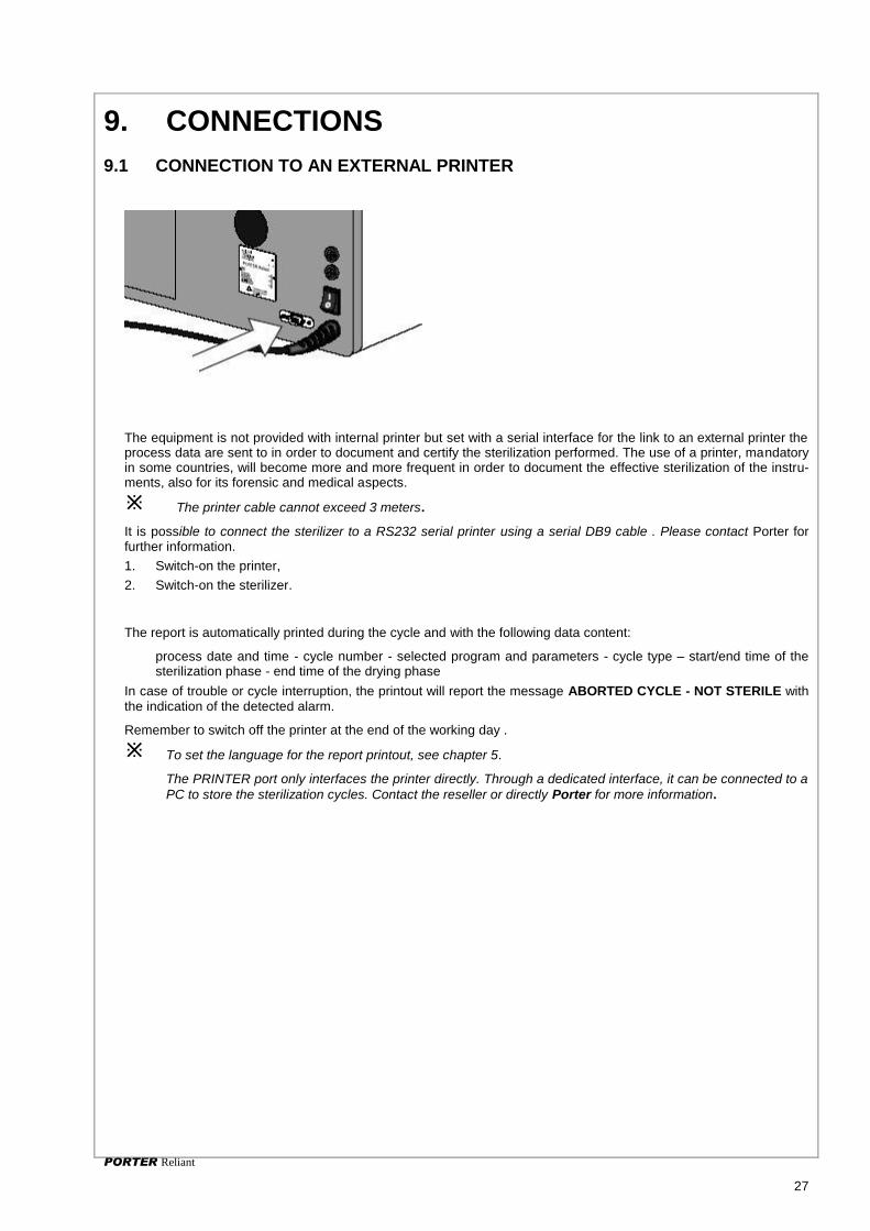
9. CONNECTIONS
9.1 CONNECTION TO AN EXTERNAL PRINTER
The equipment is not provided with internal printer but set with a serial interface for the link to an external printer the process data are sent to in order to document and certify the sterilization performed. The use of a printer, mandatory in some countries, will become more and more frequent in order to document the effective sterilization of the instru-ments, also for its forensic and medical aspects.
The printer cable cannot exceed 3 meters.
It is possible to connect the sterilizer to a RS232 serial printer using a serial DB9 cable . Please contact Porter for further information.
1. Switch-on the printer,
2. Switch-on the sterilizer.
The report is automatically printed during the cycle and with the following data content:
process date and time - cycle number - selected program and parameters - cycle type – start/end time of the sterilization phase - end time of the drying phase
In case of trouble or cycle interruption, the printout will report the message ABORTED CYCLE - NOT STERILE with the indication of the detected alarm.
Remember to switch off the printer at the end of the working day .
To set the language for the report printout, see chapter 5.
The PRINTER port only interfaces the printer directly. Through a dedicated interface, it can be connected to a
PC to store the sterilization cycles. Contact the reseller or directly Porter for more information.

PORTER Reliant
28
9.2 CONNECTION TO A COMPUTER (ONLY FOR SERVICE)
The serial port can be also used for the PC connection (key Printer Led switched off). This function is available for Service technician only, and allows to perform more accurate tests as well as a new ap-proach to service and certification aspect.
By a special SW tool, the Service technician is able to detect all the main data of the machine, and to per-form a fast troubleshooting and the repairing at reduced cost.
Moreover, the system allows the connection via modem to an authorized Service Center in order to perform a remote check-up and a periodic certification of the effective operation of the sterilizer.
Do not connect devices not supported by the manufacturer, a special cable is provided to the official service centers.
The external computing devices connected to the printer/PC interface connectors of the autoclave must comply with the standard UL60950-1
The printer /PC interface connectors shall only be connected to SELV circuits

Although the sterilizer’s average life is about 8-12 years, it is compulsory to carry out periodic controls in order to check the correct calibration and for possible wear of components. The control interval, as reported on the Service Book, is 1 Year or 1500 cycles for the ordinary maintenance, and 4 Years or 10.000 cycles for the special maintenance. The sterilizer is configured to signal on the display, as the first term comes to expire, the message “ NEED SERVICE”. This feature is in compliance with the norm EN13060 and answers to spe-cific safety requirements. The maintenance activities must be performed by authorized technicians ( provided with card or certificate released by Porter) and reported on this Service Book.
Model .......................................................... Serial Number ........................ Installation Date ............................................ Altitude .................................. Installer ............................................................................................................... Reseller ............................................................................................................... Sterilization Manager: .......................................................................................... .
Standard periodic checks
Pos Check/Activity Part code Ordinary maintenance Special maintenance *
1 Door adjustment 1 Year / 1.500 cycles
- Gasket replacement 021207 1 Year / 1.500 cycles
- Disk-door clearance check 1 Year / 1.500 cycles
- Closing force check 1 Year / 1.500 cycles
- Lubrication 1 Year / 1.500 cycles
- Component wear check 1 Year / 1.500 cycles
- Revision kit 118005 4 Years / 10.000 cycles
- Screw tightening 4 Years / 10.000 cycles
2 Calibration / Validation 1 Year
- Altitude setting check 1 Year / 1.500 cycles
3 Filter cleaning / replacement 1 Year / 1.500 cycles
- Bacterial filter replacement 021008 6 Months / 500 cycles
4 Pump feature check 1 Year / 1.500 cycles
- Pump replacement 10.000 cycles
5 Tank cleaning 1 Year / 1.500 cycles
6 Condenser cleaning 1 Year / 1.500 cycles
*) To be carried out in Porter service department (service kit code 118005 is composed by: safety valve, closing device, bacterial filter, gasket door, 3 net filter, OR for water filter)
In case of direct ship or consign for shipping the sterilizer for service center or factory repairing, include a copy of the filled-in Service Book pages.
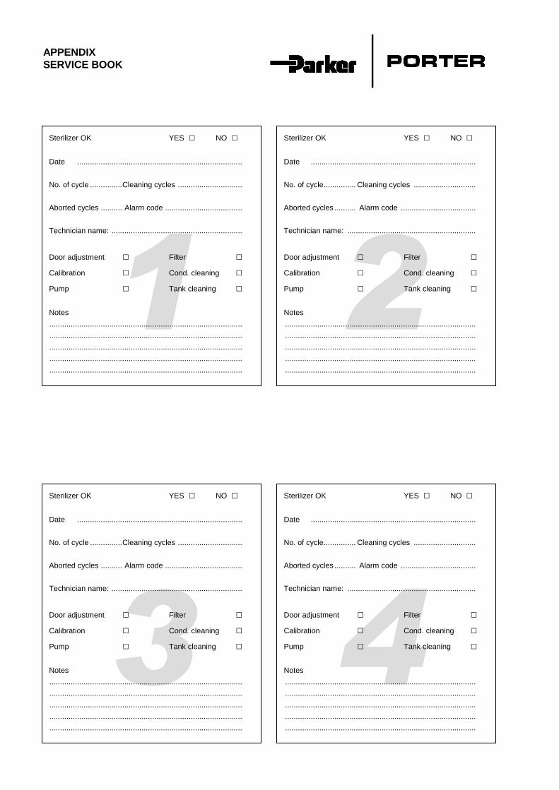
APPENDIX
SERVICE BOOK
4
6
3
6
2
6
0
1
6
0
Sterilizer OK YES □ NO □
Date .............................................................................
No. of cycle ............... Cleaning cycles ..............................
Aborted cycles .......... Alarm code ....................................
Technician name: .............................................................
Door adjustment □ Filter □
Calibration □ Cond. cleaning □
Pump □ Tank cleaning □
Notes
..........................................................................................
..........................................................................................
..........................................................................................
..........................................................................................
..........................................................................................
Sterilizer OK YES □ NO □
Date .............................................................................
No. of cycle ............... Cleaning cycles .............................
Aborted cycles .......... Alarm code ...................................
Technician name: ............................................................
Door adjustment □ Filter □
Calibration □ Cond. cleaning □
Pump □ Tank cleaning □
Notes
.........................................................................................
.........................................................................................
.........................................................................................
.........................................................................................
.........................................................................................
Sterilizer OK YES □ NO □
Date .............................................................................
No. of cycle ............... Cleaning cycles ..............................
Aborted cycles .......... Alarm code ....................................
Technician name: .............................................................
Door adjustment □ Filter □
Calibration □ Cond. cleaning □
Pump □ Tank cleaning □
Notes
..........................................................................................
..........................................................................................
..........................................................................................
..........................................................................................
..........................................................................................
Sterilizer OK YES □ NO □
Date .............................................................................
No. of cycle ............... Cleaning cycles .............................
Aborted cycles .......... Alarm code ...................................
Technician name: ............................................................
Door adjustment □ Filter □
Calibration □ Cond. cleaning □
Pump □ Tank cleaning □
Notes
.........................................................................................
.........................................................................................
.........................................................................................
.........................................................................................
.........................................................................................
APPENDIX
SERVICE BOOK

8
6
7
6
6
6
0
5
6
0
Sterilizer OK YES □ NO □
Date .............................................................................
No. of cycle ............... Cleaning cycles .............................
Aborted cycles .......... Alarm code ...................................
Technician name: ............................................................
Door adjustment □ Filter □
Calibration □ Cond. cleaning □
Pump □ Tank cleaning □
Notes
.........................................................................................
.........................................................................................
.........................................................................................
.........................................................................................
.........................................................................................
Sterilizer OK YES □ NO □
Date .............................................................................
No. of cycle ............... Cleaning cycles ..............................
Aborted cycles........... Alarm code ....................................
Technician name: .............................................................
Door adjustment □ Filter □
Calibration □ Cond. cleaning □
Pump □ Tank cleaning □
Notes
..........................................................................................
..........................................................................................
..........................................................................................
..........................................................................................
..........................................................................................
Sterilizer OK YES □ NO □
Date .............................................................................
No. of cycle ............... Cleaning cycles .............................
Aborted cycles .......... Alarm code ...................................
Technician name: ............................................................
Door adjustment □ Filter □
Calibration □ Cond. cleaning □
Pump □ Tank cleaning □
Notes
.........................................................................................
.........................................................................................
.........................................................................................
.........................................................................................
.........................................................................................
Sterilizer OK YES □ NO □
Date .............................................................................
No. of cycle ............... Cleaning cycles ..............................
Aborted cycles........... Alarm code ....................................
Technician name: .............................................................
Door adjustment □ Filter □
Calibration □ Cond. cleaning □
Pump □ Tank cleaning □
Notes
..........................................................................................
..........................................................................................
..........................................................................................
..........................................................................................
..........................................................................................
APPENDIX
SERVICE BOOK

12
60
11
60
10
0
9
6
0
Sterilizer OK YES □ NO □
Date .............................................................................
No. of cycle ............... Cleaning cycles ..............................
Aborted cycles .......... Alarm code ....................................
Technician name: .............................................................
Door adjustment □ Filter □
Calibration □ Cond. cleaning □
Pump □ Tank cleaning □
Notes
..........................................................................................
..........................................................................................
..........................................................................................
..........................................................................................
..........................................................................................
Sterilizer OK YES □ NO □
Date .............................................................................
No. of cycle ............... Cleaning cycles .............................
Aborted cycles .......... Alarm code ...................................
Technician name: ............................................................
Door adjustment □ Filter □
Calibration □ Cond. cleaning □
Pump □ Tank cleaning □
Notes
.........................................................................................
.........................................................................................
.........................................................................................
.........................................................................................
.........................................................................................
Sterilizer OK YES □ NO □
Date .............................................................................
No. of cycle ............... Cleaning cycles ..............................
Aborted cycles .......... Alarm code ....................................
Technician name: .............................................................
Door adjustment □ Filter □
Calibration □ Cond. cleaning □
Pump □ Tank cleaning □
Notes
..........................................................................................
..........................................................................................
..........................................................................................
..........................................................................................
..........................................................................................
Sterilizer OK YES □ NO □
Date .............................................................................
No. of cycle ............... Cleaning cycles .............................
Aborted cycles .......... Alarm code ...................................
Technician name: ............................................................
Door adjustment □ Filter □
Calibration □ Cond. cleaning □
Pump □ Tank cleaning □
Notes
.........................................................................................
.........................................................................................
.........................................................................................
.........................................................................................
.........................................................................................
APPENDIX
SERVICE BOOK


Änderungen im Zuge
technischer Weiterent-
wicklung vorbehalten.
We reserve the right to make
changes which may be due to
technical improvements.
Sous réserve de modifi-
cations dues au progrès
technique.
Reservados los derechos de
modificatiòn en virtud del
progreso tècnico.
Ci riserviamo il diritto di
apportare modifiche a se-
guito di migliorie tecniche.
Copyright Dental X 2008 Printed in Italy
DENTAL X s.r.l. Via Marzotto 11 36031 Dueville (VI) Italy Tel. +39 0444 367400 Fax +39 0444 367436
e-mail: [email protected] http://www.dentalx.it