Embed Size (px)
Citation preview
Manual with Spare Parts List
DISPAX REACTOR® DR 3-6/A
MODEL: DR 3-6/A SERIAL NUMBER 1071
CAUTION: Read this manual completely before using the Dispax Reactor®.
IKA® Works, Inc. 2635 North Chase Pkwy SE W ilmington, NC 28405 U.S.A 1-910-452-7059
2
1 TABLE OF CONTENTS
SUBJECT PAGE I. SAFETY WARNINGS 4 A. General Safety 4 B. Equipment Misuse Hazard 4 C. Moving Parts Hazard 5 D. Fire or Explosion Hazard 5 E. Sound Level Ratings 5 F. Temperature Limitations 6 II. DESCRIPTION 6 A. Unit Drive 6 B. Seal Housing 6 C. Dispersing chamber 7 III. COMMISSIONING THE UNIT 7 A. Foundation and Piping Connections 7 B. Mechanical Seal Assembly 8 C. Power Supply 8 D. Activating the System 9 IV. MAINTENANCE 10 A. Gear and Bearings 10 B. Mechanical Seal 10 C. Rotor/Stator Generators 11
IKA® Works, Inc. 2635 North Chase Pkwy SE W ilmington, NC 28405 U.S.A 1-910-452-7059
3
2 TABLE OF CONTENTS
SUBJECT PAGE V. ASSEMBLY/DISASSEMBLY 11 A. Exchange of Generators 11 B. Exchange or Inspection of the Mechanical Seal 12 C. Disassembly/Assembly of the Gearbox and Shaf t 13
VI. ORDERING SPARE PARTS 15 VII. APPENDICES 16 A. DR 3-6/A Unit Assembly Print B. DR 3-6/A Unit Parts List C. DR 3-6/A Unit Installation Print D. Flange Adapter Parts List E. Flange Adapter Assembly Print F. R4269/18 Double Mechanical Seal Assembly Print G. R4269/18 Double Mechanical Seal Parts List H. Miscellaneous Product Information
IKA® Works, Inc. 2635 North Chase Pkwy SE W ilmington, NC 28405 U.S.A 1-910-452-7059
4
2.1 I. SAFETY WARNINGS
A. General Safety 1. ALWAYS wear safety glasses when using power tools to repair this equipment. 2. When dangerous f luids are being processed t hrough the unit, wear protective gloves, glasses, etc. when working on or around the equipment. 3. DO NOT operate a unit that is leaking, damaged, corroded or otherwise unable to contain the process f luid. 4. ALWAYS make sure safety shut-off switches, regulators, pressure relief
valves, gauges, etc. are working properly bef ore starting the unit.
5. DO NOT process incompatible fluids through the unit. Consult your distributor if you are not sure about compatibility of fluids with the wetted parts or the elastomers.
6. Before starting the unit, make certain the inlet and outlet flanges are
clear and safe and that all personnel are standing at a saf e distance. 7. ALWAYS disconnect power mains whenever repairing or disassembling the unit. B. Equipment Misuse Hazard
1. General Safety - Any misuse of this equipment such as over-pressurization, modifying parts, processing incompatible fluids, or using worn or damaged parts is not recommended. Any of these circumstances could result in splashing or spraying into the eyes or skin, possible serious bodily injury, f ire, explosion or property damage.
2. Noise - It is recommended that proper ear protection be worn when
working near this equipment. 3. Seal Failure - When processing dangerous fluids, take all precautions
necessary for containment and clean-up in case of seal or elastomer failure.
4. Installation - Never allow the piping system to be supported by the unit’s
inlet or outlet flanges. The flanges are not designed to support any
IKA® Works, Inc. 2635 North Chase Pkwy SE W ilmington, NC 28405 U.S.A 1-910-452-7059
5
structural weight and failure of the unit may result. The use of flexible piping connections is highly recommended.
C. Moving Parts Hazard
The generator sets within the dispersing chamber of the unit rotate at great velocities. Therefore, keep all objects clear of the inlet and outlet flanges at all times. Never attempt to repair the unit while it is operating, otherwise serious bodily injury may occur.
D. Fire or Explosion Hazard
Static electricity can be created by the flow of fluid through the unit or by the rotating action of the generators. If the unit is not properly grounded, sparking may occur, and the system may become hazardous. Sparks can ignite fumes or vapor and cause an explosion.
If you experience static sparking or even a slight shock when operating the unit, do not continue until it is properly grounded.
Unit, valves, discharge and supply lines as well as containers must be grounded. These items must be grounded when handling flammable fluids and when static electricity discharge is a hazard.
To ground the unit, connect a ground wire to any accessible point of attachment such as the basef rame. E. Sound Level Ratings
DISPAX REACTORS® should not exceed 90 dB(A) when processing pure water. Generator configurations and process fluids will tend to vary noise level readings slightly. Readings on the units are conducted using a Simpson model 886 sound level indicator “A” scale. Readings are made at a distance of 1 meter from the unit and 0.5 meters off the floor. It is assumed that the unit will be installed at f loor level.
IKA® Works, Inc. 2635 North Chase Pkwy SE W ilmington, NC 28405 U.S.A 1-910-452-7059
6
F. Temperature Limitations
Maximum temperature limitations are based on mechanical stress only. Certain chemicals will reduce the maximum safe operating temperatures of DISPAX REACTORS®. Consult the supplier for compatibility and temperature limits.
The limiting factor on operating temperatures for DISPAX REACTORS® is the material of the o-rings in both the seal and the unit. Failure of the o-rings should occur before any damage is done to the sea l faces, wetted parts, etc..
Temperature Limits of Various Elastomer Types:
Viton®: -40ºF (-40ºC) to 350ºF (176ºC) Teflon®: 40ºF (4ºC) to 220ºF (105ºC)
TES: 40ºF (4ºC) to 220ºF (105ºC) Kalrez®: -40ºF (-40ºC) to 500ºF (260ºC) EPR: -70ºF (-57ºC) to 275ºF (135ºC)
2.2 II. DESCRIPTION
The DISPAX REACTOR®, DR 3-6/A, is a high shear, high-speed disperser designed for in-line use. The unit is designed to create emulsions and suspensions in pilot plant/small production systems.
The machine is constructed in three sections:
A. Unit Drive
The standard unit consists of a 5 HP or 7.5 HP, 3-phase, 3600 RPM motor (other configurations are available). Through a gearbox system, the motor turns a driveshaft to approximately 8000 RPM.
2.2.1 Seal Housing
The seal housing contains alignment bearings and the double mechanical seal assembly. The latter is designed to isolate the drive and bearing items from the customer’s process fluid.
IKA® Works, Inc. 2635 North Chase Pkwy SE W ilmington, NC 28405 U.S.A 1-910-452-7059
7
2.2.2 Dispersing chamber
The jacketed, cylindrical housing contains the three (3) rotor/stator generators and spacers, which, with rotors turning at 8000 RPM, develop the turbulence necessary to achieve the desired mixing results. The inlet/outlet flanges are also part of the Dispersing chamber assembly.
NOTE: The machine may only be used with fluids that are free flowing and are able to be
pumped.
This DISPAX REACTOR® unit will operate with process fluids that are fed at pressures UP TO approximately 4.5 Bar, or 65 psig, at the unit’s inlet. Since the unit does not develop inlet suction, it must be provided with sufficient positive flow, either by a gravity fed system, or by a positive displacement pump. Centrifugal pumps, while they have been used successfully in the past, are not recommended since system back pressure may adversely affect flow rate and overall pump performance.
If this machine is gravity fed, it will develop various levels of discharge pressure. These levels depend on the following: back pressure (head), fluid viscosity, and fluid behavior under high shear. In short, if specific flow rates (GPM) are required - a positive displacement pump should be installed ahead or upstream of the unit at a minimum distance of approximately 10 pipe diameters.
The design flow rates published, for the various generator combinations available, are based on water (cP=1), gravity fed with no backpressure.
III. COMMISSIONING THE UNIT FOR OPERATION
See Unit Assembly Drawing
A. Foundation and Piping Connections The DISPAX REACTOR® may be supplied with several dif ferent baseframes, some
with casters and handles for mobility. The unit may also be mounted to any firm, level surface using the bolt holes on the lower f rame of the motor, itself .
Connect plant inlet/outlet piping as part of the required process scheme. Make every attempt to use pipe ID’s which correspond to the inlet/outlet flange ID’s (check parts list in this manual to determine flange ID’s). Radically dissimilar ID’s may result in improper f luid flow through the unit.
IKA® Works, Inc. 2635 North Chase Pkwy SE W ilmington, NC 28405 U.S.A 1-910-452-7059
8
B. Mechanical Seal Assembly
The mechanical seal assembly is the most vulnerable part of this, or any other, high-speed mechanical device. While the machine is in operation, the seal must be cooled and pressurized. Water, or any suitable free-flowing heat transfer liquid, compatible with the process fluid, may be used. Make sure that the coolant is solids-free. If plant-cooling water is used, and chlorine is used to treat this water for bacterial or slime control, please consult the supplier before operating the unit. Do not use de-ionized water if possible. If this is unavoidable, please consult the supplier. Well-water hardness may also affect the seal. In short, softened water is recommended.
Connect metal tubing to the ¼ inch seal ports (59, 35). Coolant inlet should be the “lower” of the two ports. This eliminates trapped air bubbles in the seal housing. Copper or stainless steel tubing should be used. The coolant flow must be at least 20-30 psig higher than the inlet pressure of the process fluid. Further, the coolant pressure must be measured at the seal outlet (i.e.: seal backpressure is used as a standard). The seal in the DR 3-6/A can withstand up to 90 psig - therefore, maximum process fluid inlet pressure is 90-20=70 psig, but maximum 60 psig is preferable (90-30=60 psig). Should higher pressures be required, a DR 3-6/6P unit should be used instead. If so, consult your IKA Sales Engineer.
NOTE: Coolant flowrate should be about 0.5 - 1.0 gpm. As an option, thermosyphon seal cooling systems are available at an additional cost. Contact IKA® Works, Inc. for more information.
C. POWER SUPPLY
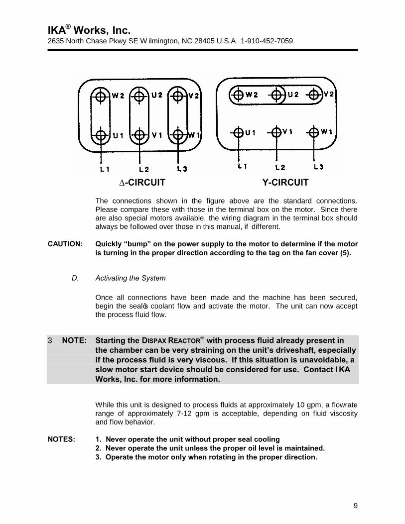
The user is responsible for connecting the power supply to the DISPAX REACTOR. The DISPAX REACTOR is supplied without cables and switches. Please use the wiring diagram from the illustration on page 9, as well as the note in the terminal box of the motor as a guide to connecting the machine to its power supply.
CAUTION: Trained personnel should only perform the electrical connection of the
machine. The connection of the machine must corre-spond to any applicable standards for the country where the machine is located. When connecting the motor, ensure that the motor voltage and power supply are identical. The motor voltage can be found on the identification plate of the motor.
IKA® Works, Inc. 2635 North Chase Pkwy SE W ilmington, NC 28405 U.S.A 1-910-452-7059
9
∆-CIRCUIT Y-CIRCUIT
The connections shown in the figure above are the standard connections. Please compare these with those in the terminal box on the motor. Since there are also special motors available, the wiring diagram in the terminal box should always be followed over those in this manual, if different.
CAUTION: Quickly “bump” on the power supply to the motor to determine if the motor
is turning in the proper direction according to the tag on the fan cover (5).
D. Activating the System
Once all connections have been made and the machine has been secured, begin the seal’s coolant flow and activate the motor. The unit can now accept the process f luid flow.
3 NOTE: Starting the DISPAX REACTOR with process fluid already present in the chamber can be very straining on the unit’s driveshaft, especially if the process fluid is very viscous. If this situation is unavoidable, a slow motor start device should be considered for use. Contact I KA Works, Inc. for more information.
While this unit is designed to process fluids at approximately 10 gpm, a flowrate range of approximately 7-12 gpm is acceptable, depending on fluid viscosity and flow behavior.
NOTES: 1. Never operate the unit without proper seal cooling
2. Never operate the unit unless the proper oil level is maintained. 3. Operate the motor only when rotating in the proper direction.

IKA® Works, Inc. 2635 North Chase Pkwy SE W ilmington, NC 28405 U.S.A 1-910-452-7059
10
4. Take all precautions (including the use of screens) to insure that foreign objects do not flow into the dispersing chamber.
IV. MAINTENANCE
A. Gear and Bearings
3.1.1.1.1 See Unit Assembly Drawing
As this is a high speed gearing, it is recommenced that the gearbox lubricant be changed after the first 300-400 hours of operation. To do this, first shut off and/or lock out the power supply, and then follow the directions below.
1. Loosen and remove the ventilation filter screw (43).
2. Loosen and remove the oil drain plug (11). Oil should flow freely. 3. Replace and tighten the drain plug (11).
4. Refill the gearbox with standard HP oil (30W may be used). The gearbox should be filled until the oil reaches halfway up the sight glass (15).
After the first 800 operating hours, the roller bearings (47, 51, 67) should be cleaned and greased, using grease with a drop point of 150o C, or better. Please refer to Section V - “Assembly/Disassembly” below for instructions.
B. Mechanical Seal
3.1.1.1.2 See Double Mechanical Seal Drawing
The double mechanical seal assembly should be checked approximately once every two (2) months (more often if abrasive materials are being processed). Clean all parts and check for any wear. However, do not clean seal parts with solvents without consulting your IKA® Sales Engineer.
For best results - after each production run, let the dispersing chamber drain and dry, but maintain seal coolant flow for 3-5 minutes. This will remove any residual heat from the seal and flush any solids that may have entered the seal.
Should the inspection reveal worn or cracked seal faces, replace the damaged parts. Do not reuse damaged faces, as leaking may occur.
IKA® Works, Inc. 2635 North Chase Pkwy SE W ilmington, NC 28405 U.S.A 1-910-452-7059
11
NOTE: A leaking seal does not always indicate damaged parts. Disassemble the seal, clean all parts, and reassemble. If leakage continues, it may be necessary to replace some of the parts, however, a seal failure may not necessitate replacement of the entire seal assembly.
C. Rotor/Stator Generators
3.1.1.1.3 See Unit Assembly Drawing, pos. 60 -65 Considering the precision (and expense) of these items, do the following:
1. After a process run, flush the unit with water or appropriate cleaner, doing this while the unit is running will effectively clean the generators. This operation is essential if the process fluid tends to solidify or “set-up”.
2. Preventing foreign objects from entering the dispersing chamber is the most
effective way of protecting the generators. This is especially important with new piping/process systems that may contain weld slag, construction debris, etc.
3.2 V. ASSEMBLY/DISASSEMBLY
3.2.1.1.1.1 See Unit Assembly and Double Mechanical Seal Drawings NOTE: Before proceeding, disconnect or lock out electrical supply.
A. Exchange of Generators
Each rotor/stator set is interchangeable in position within the dispersing chamber. 1. Disconnect inlet process piping. 2. Loosen and remove the four cap nuts and washers (Unit Assembly Drawing,
pos. 34, 33) and remove the inlet flange (56). 3. Slide off the cooling jacket cylinder (57).
4. Loosen and remove the grease fitting (50) and rotate the shaft until the bore hole appears. Insert a metal rod through the hole to secure the drive shaft. Loosen and remove the cap nut and washer (31, 32) found on the end of the drive shaft (29).
IKA® Works, Inc. 2635 North Chase Pkwy SE W ilmington, NC 28405 U.S.A 1-910-452-7059
12
5. Carefully remove the first stator (65), rotor (64), and rotor distance spacer (27).
6. Follow step 5 until the other two sets of generators have been removed.
7. Remove the stator distance spacer (26). Assemble in reverse order.
B. Exchange or Inspection of the Mechanical Seal 1. Follow steps IV.A.1-7 above.
2. If necessary, loosen and remove coolant inlet and outlet ports from the unit
housing (Unit Assembly Drawing, pos. 59, 35). 3. Loosen and remove the four hex head screws and washers (20, 19). 4. Slide off the dispersing chamber (55). 5. Loosen and remove the four slotted screws (22). 6. Remove the seal cover (21).
7. Remove the counter slip ring and the O-ring (Seal Assembly drawing, pos. 14,15) from the seal cover (Unit Assembly drawing, pos. 21).
8. Remove the remaining items (refer to Seal Assembly drawing, pos. 1, 2, 3,
4, 5, 6, 9, 11) from the dispersing chamber (Unit Assembly drawing, pos. 55).
Assemble in reverse order. If the process fluid is changed, consider whether the seal faces and O-rings are still suitable. If in doubt, contact the supplier or check the seal materials on other devices in the plant.
C. Disassembly/Assembly of the Gearbox and Shaft
3.2.1.1.1.1.1 See Unit Assembly Drawing 1. Follow steps IV.A.1-7, and IV.B.1-8, above. 2. Drain oil from gearbox (see “Maintenance” section).
IKA® Works, Inc. 2635 North Chase Pkwy SE W ilmington, NC 28405 U.S.A 1-910-452-7059
13
3. Loosen and remove the four socket head screws and washers (Unit Assembly Drawing, pos. 6, 7, 8) and remove gearbox housing completely from the motor.
Before attempting further work, take the complete assembly (gearbox, shaft, bearings, etc.) to a clean workbench area. This will facilitate further disassembly described in the remaining steps.
4. Remove the retaining ring (53), using retaining ring pliers. 5. Remove the nilos ring (68). 6. Remove the bearing distance spacer (49). 7. Remove the retaining ring (52). 8. Replace the cap nut (32) on the “front” end of the drive shaft. Using a
rubber-coated mallet, carefully tap the drive shaft in the direction towards the motor end. When loose, pull the shaft out, leaving both “front” ball bearings (51, 67) in place.
9. Remove bearing (51).
10. Remove the bearing distance spacer (46). 11. Remove both disc springs (66). Note the relative position of these springs.
They contact each other apex-to-apex. They will eventually be reassembled in the same relative positions.
12. Remove the bearing (67).
13. From the drive shaft, remove the hex nut (39), lock washer (40), and flat washer (41).
14. Remove the small pinion gear (13) and the key (42). 15. Remove the rotary shaft seal (44). 16. Remove the retaining ring (45). Slide off the bearing (47).
Reassembly: keep the cap nut (32) attached to the shaft.
1. Slide bearing (67) onto the shaft - Note: all ball bearings should have their “black” face towards the dispersing chamber.
2. Screw the hex nut (39) onto the motor end of the shaft.

IKA® Works, Inc. 2635 North Chase Pkwy SE W ilmington, NC 28405 U.S.A 1-910-452-7059
14
3. After placing small block of wood, etc., on table, place gearbox over it (shaft well facing vertical) and then slide the shaft with the bearing (67) down through the well until it comes to rest.
4. Replace both disc springs (66), apex-to-apex, down the shaft. 5. Press down on springs and attach spacer ring (46).
6. Slide on bearing (51) and retaining ring (52) in the groove cut into the gearbox housing.
7. Replace the bearing distance spacer (49) and retaining ring (52). 8. Replace the nilos ring (68). 9. Replace the retaining ring (53).
10. Moving to the “back” of the unit (lift up gearbox to horizontal), replace the bearing (47) - remove the hex nut (39) for convenience.
11. Set the retaining ring (45), and rotary shaft seal (44).
12. Insert key (42) and slide on the small pinion gear (13), followed by the flat washer (41), and the lock washer (40).
13. Finally, replace and tighten the hex nut (39). After attaching gearbox to
motor, refill with oil. NOTE: The parts above are made for a “tight” fit. A little Silicon grease may be used to make
the parts slide easier. CAUTION: While firmness may be required, never use excessive force or use a tool that
may damage the parts.
IKA® Works, Inc. 2635 North Chase Pkwy SE W ilmington, NC 28405 U.S.A 1-910-452-7059
15
3.3
3.4
3.5
3.6 VI. ORDERING SPARE PARTS
When ordering spare parts, it is necessary to include the following information: A. Unit model, i.e. DR 3-6/A B. Unit Serial number. C. Drawing, position number and description of part(s) required. Example:
For DISPAX REACTOR®, DR 3-6/A, serial no. 2212, one rotor, P001829, as per drawing P000296, position 60.
IKA® Works, Inc. 2635 North Chase Pkwy SE W ilmington, NC 28405 U.S.A 1-910-452-7059
16
VII. APPENDICES
A. DR 3-6/A Unit Assembly Print – P000296
B. DR 3-6/A Spare Parts List – P006216 C. DR 3-6/A Unit Installation Print – P002351
D. Flange Adapter Parts List – P002267 E. Flange Adapter Assembly Print– P002267 F. R4269/18 Mechanical Seal Assembly Print – P000325
G. R4269/18 Mechanical Seal Parts List – P004156
H. Miscellaneous Product Information
IKA® Works, Inc. 2635 North Chase Pkwy SE W ilmington, NC 28405 U.S.A 1-910-452-7059
17
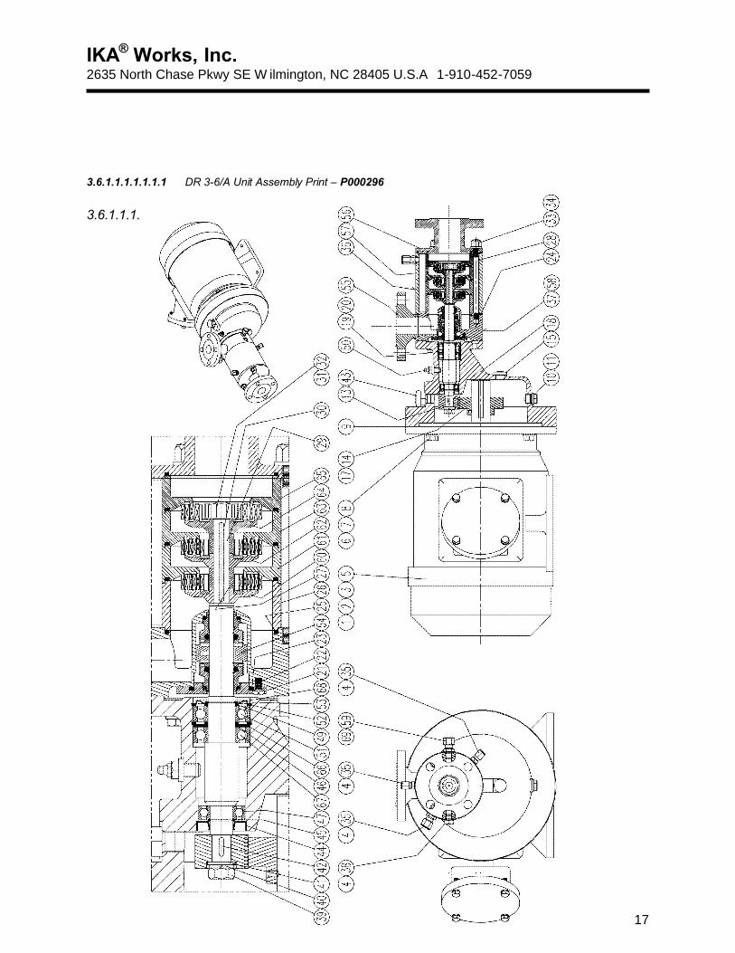
3.6.1.1.1.1.1.1.1 DR 3-6/A Unit Assembly Print – P000296
3.6.1.1.1.1.1.1.2
IKA® Works, Inc. 2635 North Chase Pkwy SE W ilmington, NC 28405 U.S.A 1-910-452-7059
18
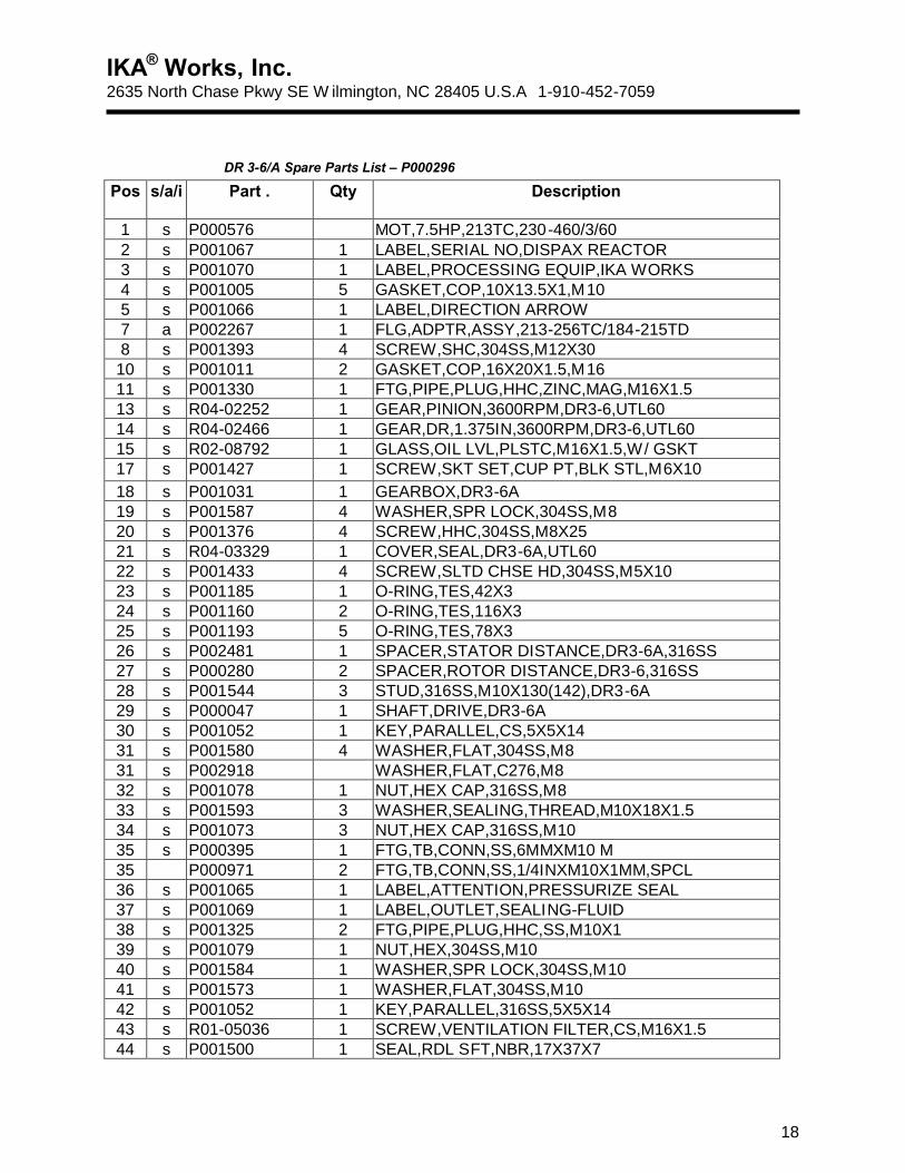
DR 3-6/A Spare Parts List – P000296 Pos s/a/i Part . Qty Description
1 s P000576 MOT,7.5HP,213TC,230-460/3/60 2 s P001067 1 LABEL,SERIAL NO,DISPAX REACTOR 3 s P001070 1 LABEL,PROCESSING EQUIP,IKA WORKS 4 s P001005 5 GASKET,COP,10X13.5X1,M10 5 s P001066 1 LABEL,DIRECTION ARROW 7 a P002267 1 FLG,ADPTR,ASSY,213-256TC/184-215TD 8 s P001393 4 SCREW,SHC,304SS,M12X30
10 s P001011 2 GASKET,COP,16X20X1.5,M16 11 s P001330 1 FTG,PIPE,PLUG,HHC,ZINC,MAG,M16X1.5 13 s R04-02252 1 GEAR,PINION,3600RPM,DR3-6,UTL60 14 s R04-02466 1 GEAR,DR,1.375IN,3600RPM,DR3-6,UTL60 15 s R02-08792 1 GLASS,OIL LVL,PLSTC,M16X1.5,W/ GSKT 17 s P001427 1 SCREW,SKT SET,CUP PT,BLK STL,M6X10 18 s P001031 1 GEARBOX,DR3-6A 19 s P001587 4 WASHER,SPR LOCK,304SS,M8 20 s P001376 4 SCREW,HHC,304SS,M8X25 21 s R04-03329 1 COVER,SEAL,DR3-6A,UTL60 22 s P001433 4 SCREW,SLTD CHSE HD,304SS,M5X10 23 s P001185 1 O-RING,TES,42X3 24 s P001160 2 O-RING,TES,116X3 25 s P001193 5 O-RING,TES,78X3 26 s P002481 1 SPACER,STATOR DISTANCE,DR3-6A,316SS 27 s P000280 2 SPACER,ROTOR DISTANCE,DR3-6,316SS 28 s P001544 3 STUD,316SS,M10X130(142),DR3-6A 29 s P000047 1 SHAFT,DRIVE,DR3-6A 30 s P001052 1 KEY,PARALLEL,CS,5X5X14 31 s P001580 4 WASHER,FLAT,304SS,M8 31 s P002918 WASHER,FLAT,C276,M8 32 s P001078 1 NUT,HEX CAP,316SS,M8 33 s P001593 3 WASHER,SEALING,THREAD,M10X18X1.5 34 s P001073 3 NUT,HEX CAP,316SS,M10 35 s P000395 1 FTG,TB,CONN,SS,6MMXM10 M 35 P000971 2 FTG,TB,CONN,SS,1/4INXM10X1MM,SPCL 36 s P001065 1 LABEL,ATTENTION,PRESSURIZE SEAL 37 s P001069 1 LABEL,OUTLET,SEALING-FLUID 38 s P001325 2 FTG,PIPE,PLUG,HHC,SS,M10X1 39 s P001079 1 NUT,HEX,304SS,M10 40 s P001584 1 WASHER,SPR LOCK,304SS,M10 41 s P001573 1 WASHER,FLAT,304SS,M10 42 s P001052 1 KEY,PARALLEL,316SS,5X5X14 43 s R01-05036 1 SCREW,VENTILATION FILTER,CS,M16X1.5 44 s P001500 1 SEAL,RDL SFT,NBR,17X37X7
IKA® Works, Inc. 2635 North Chase Pkwy SE W ilmington, NC 28405 U.S.A 1-910-452-7059
19
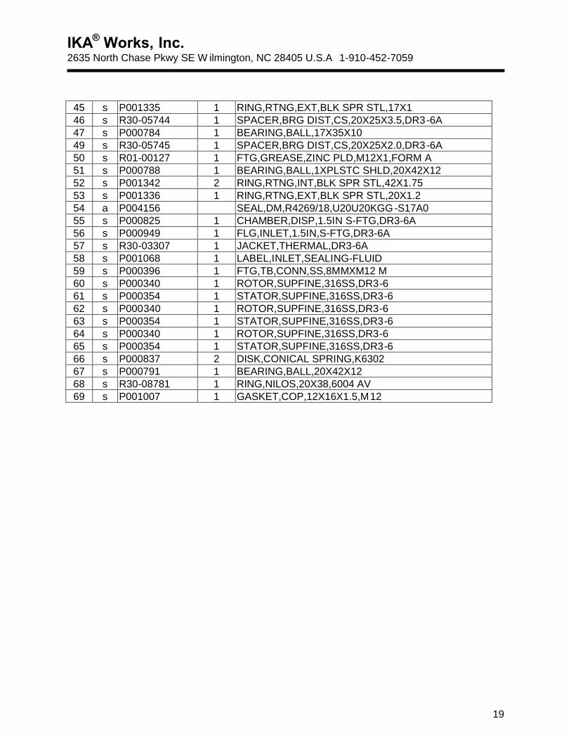
45 s P001335 1 RING,RTNG,EXT,BLK SPR STL,17X1 46 s R30-05744 1 SPACER,BRG DIST,CS,20X25X3.5,DR3-6A 47 s P000784 1 BEARING,BALL,17X35X10 49 s R30-05745 1 SPACER,BRG DIST,CS,20X25X2.0,DR3-6A 50 s R01-00127 1 FTG,GREASE,ZINC PLD,M12X1,FORM A 51 s P000788 1 BEARING,BALL,1XPLSTC SHLD,20X42X12 52 s P001342 2 RING,RTNG,INT,BLK SPR STL,42X1.75 53 s P001336 1 RING,RTNG,EXT,BLK SPR STL,20X1.2 54 a P004156 SEAL,DM,R4269/18,U20U20KGG-S17A0 55 s P000825 1 CHAMBER,DISP,1.5IN S-FTG,DR3-6A 56 s P000949 1 FLG,INLET,1.5IN,S-FTG,DR3-6A 57 s R30-03307 1 JACKET,THERMAL,DR3-6A 58 s P001068 1 LABEL,INLET,SEALING-FLUID 59 s P000396 1 FTG,TB,CONN,SS,8MMXM12 M 60 s P000340 1 ROTOR,SUPFINE,316SS,DR3-6 61 s P000354 1 STATOR,SUPFINE,316SS,DR3-6 62 s P000340 1 ROTOR,SUPFINE,316SS,DR3-6 63 s P000354 1 STATOR,SUPFINE,316SS,DR3-6 64 s P000340 1 ROTOR,SUPFINE,316SS,DR3-6 65 s P000354 1 STATOR,SUPFINE,316SS,DR3-6 66 s P000837 2 DISK,CONICAL SPRING,K6302 67 s P000791 1 BEARING,BALL,20X42X12 68 s R30-08781 1 RING,NILOS,20X38,6004 AV 69 s P001007 1 GASKET,COP,12X16X1.5,M12
IKA® Works, Inc. 2635 North Chase Pkwy SE W ilmington, NC 28405 U.S.A 1-910-452-7059
20
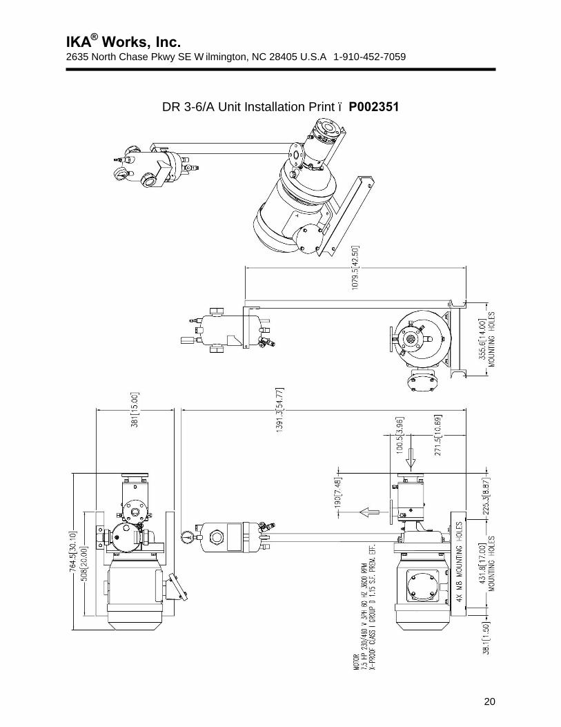
DR 3-6/A Unit Installation Print – P002351
IKA® Works, Inc. 2635 North Chase Pkwy SE W ilmington, NC 28405 U.S.A 1-910-452-7059
21
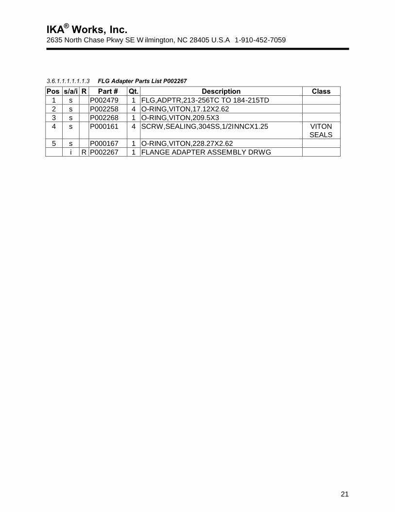
3.6.1.1.1.1.1.1.3 FLG Adapter Parts List P002267
Pos s/a/i R Part # Qt. Description Class 1 s P002479 1 FLG,ADPTR,213-256TC TO 184-215TD 2 s P002258 4 O-RING,VITON,17.12X2.62 3 s P002268 1 O-RING,VITON,209.5X3 4 s P000161 4 SCRW,SEALING,304SS,1/2INNCX1.25 VITON
SEALS 5 s P000167 1 O-RING,VITON,228.27X2.62 i R P002267 1 FLANGE ADAPTER ASSEMBLY DRWG
IKA® Works, Inc. 2635 North Chase Pkwy SE W ilmington, NC 28405 U.S.A 1-910-452-7059
22
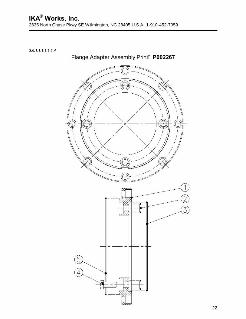
3.6.1.1.1.1.1.1.4
Flange Adapter Assembly Print– P002267
IKA® Works, Inc. 2635 North Chase Pkwy SE W ilmington, NC 28405 U.S.A 1-910-452-7059
23
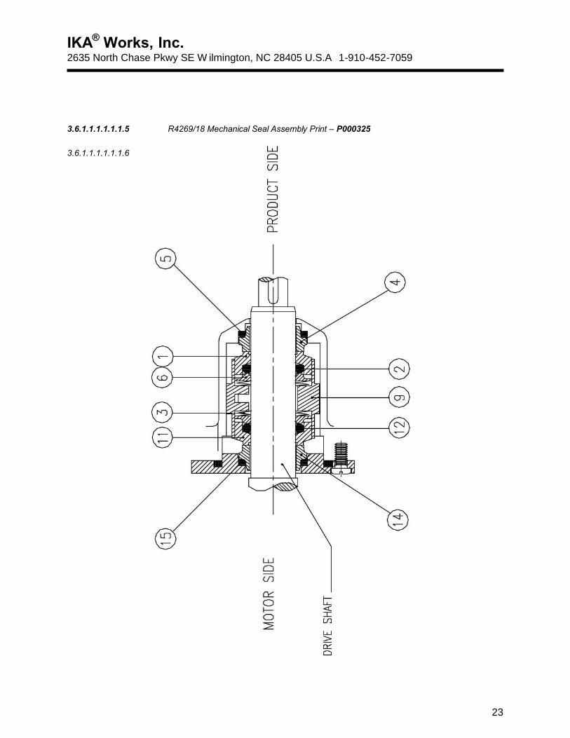
3.6.1.1.1.1.1.1.5 R4269/18 Mechanical Seal Assembly Print – P000325
3.6.1.1.1.1.1.1.6
IKA® Works, Inc. 2635 North Chase Pkwy SE W ilmington, NC 28405 U.S.A 1-910-452-7059
24
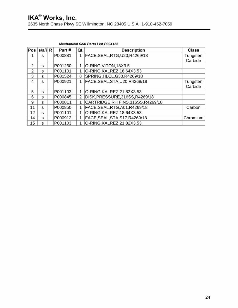
Mechanical Seal Parts List P004156
Pos s/a/i R Part # Qt. Description Class 1 s P000881 1 FACE,SEAL,RTG,U20,R4269/18 Tungsten
Carbide 2 s P001260 1 O-RING,VITON,18X3.5 2 s P001101 1 O-RING,KALREZ,18.64X3.53 3 s P001524 8 SPRING,HLCL,G30,R4269/18 4 s P000921 1 FACE,SEAL,STA,U20,R4269/18 Tungsten
Carbide 5 s P001103 1 O-RING,KALREZ,21.82X3.53 6 s P000845 2 DISK,PRESSURE,316SS,R4269/18 9 s P000811 1 CARTRIDGE,RH FINS,316SS,R4269/18
11 s P000850 1 FACE,SEAL,RTG,A01,R4269/18 Carbon 12 s P001101 1 O-RING,KALREZ,18.64X3.53 14 s P000912 1 FACE,SEAL,STA,S17,R4269/18 Chromium 15 s P001103 1 O-RING,KALREZ,21.82X3.53