Embed Size (px)
Citation preview
NETWORK REDUCTION (YBR)
Use
r Man
ual
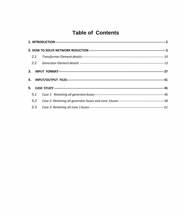
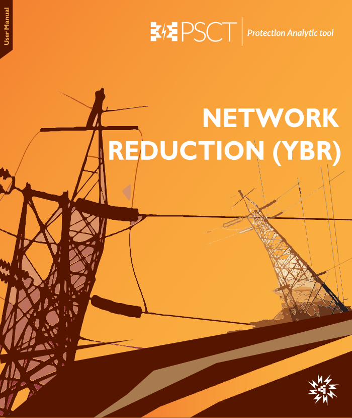
Table of Contents 1. INTRODUCTION -------------------------------------------------------------------------------------------------------- 2
2. HOW TO SOLVE NETWORK REDUCTION ------------------------------------------------------------------------ 3
2.1 Transformer Element details ----------------------------------------------------------------------------- 10
2.2 Generator Element details ------------------------------------------------------------------------------- 13
3. INPUT FORMAT --------------------------------------------------------------------------------------------------- 37
4. INPUT/OUTPUT FILES ------------------------------------------------------------------------------------------- 41
5. CASE STUDY ------------------------------------------------------------------------------------------------------- 45
5.1 Case 1: Retaining all generator buses ----------------------------------------------------------------- 46
5.2 Case 2: Retaining all generator buses and zone 1 buses ------------------------------------------ 58
5.3 Case 3: Retaining all zone 1 buses ---------------------------------------------------------------------- 61

MiP-PSCT YBR
Power Research and Development Consultants Pvt. Ltd Page 2
1. INTRODUCTION
POWERYBR is designed to provide the static and dynamic equivalents for the power system. In case of static equivalent, program determines the bus admittance matrix (Ybus) as seen from the desired nodes by eliminating the rest of the nodes. In case of dynamic equivalent, a single machine equivalent circuit is determined. The methodology is an extension of the Thevenin theorem to electromechanical circuits. It is often necessary to obtain network equivalents for proper representation in various analysis such as transient and dynamic stability analysis. In POWERYBR sparse storage and matrix ordering techniques are used to reduce the memory requirements. The methodology used for static equivalent, wherein all the generator buses in the system are retained consists of -
• Formation of positive sequence sparse Ybus for the given power system. In the
Ybus formation, shunt elements at the buses, which are to be retained, will not be added to the corresponding diagonal elements.
• Finding the columns of the positive sequence Zbus for the nodes to be retained. • Assembling the Zbus for the reduced system from the above columns of Zbus. • Inverting the Zbus to find the positive sequence Ybus for the reduced system. • Above analysis are done for negative and zero sequence networks.
In case of dynamic equivalent, the procedure involved is -
• Internal system is identified. All the buses, which are external to the area of
interest, and connected directly to the internal system nodes, are identified. These are the nodes to be retained.
• An equivalent generator is considered, connected to the retained nodes in the external system.
• The single machine electromechanical circuit replaces generators in the external system.
The program input data is through an ASCII file, the format of which is described in chapter 2. In chapter 3, input and output files are given. Chapter 4 gives the case study, wherein the data file preparation for obtaining the network equivalents for sample systems are discussed along with the analysis of the results.
MiP-PSCT YBR
Power Research and Development Consultants Pvt. Ltd Page 3
2. HOW TO SOLVE NETWORK REDUCTION
EXAMPLE: Network Reduction
For a typical 24 Bus System with maximum generation as slack bus. The Single Line Diagram is shown in fig-1. Element parameters are specified in the element tables.
1. Generate a Single line diagram using MiP-PSCT Power system Network Editor
simultaneously Compute the Electrical parameters in p.u. on 100MVA base. 2. Do Load Flow Analysis in Fast decoupled method, tolerance of 0.001. 3. Do Ybus Network Reduction using following methods
Case1: Retaining all generator buses Network reduced with retaining all the buses to which the generators are connected, such as 1, 2, 3 and 4.
Case2 : Retaining all Generator buses and Zone 1 buses Network reduced with retaining all the buses to which the generators are connected, and buses belonging to Zone1, such as 5, 6, 7, 8, 9, 10, 11, 12, 13, 14, 15, 16, and 17.
Case 3: Retaining all Zone 1 buses Network reduced with retaining all the Zone1 buses, such as 1, 4, 5, 6, 7, 8, 9, 10, 11, 12, 13, 14, 15, 16, and 17.
Case 4: Network Reduction for Dynamic Stability study. Network reduced with retaining all the buses to which the generators are connected taking the option Dynamic Stability
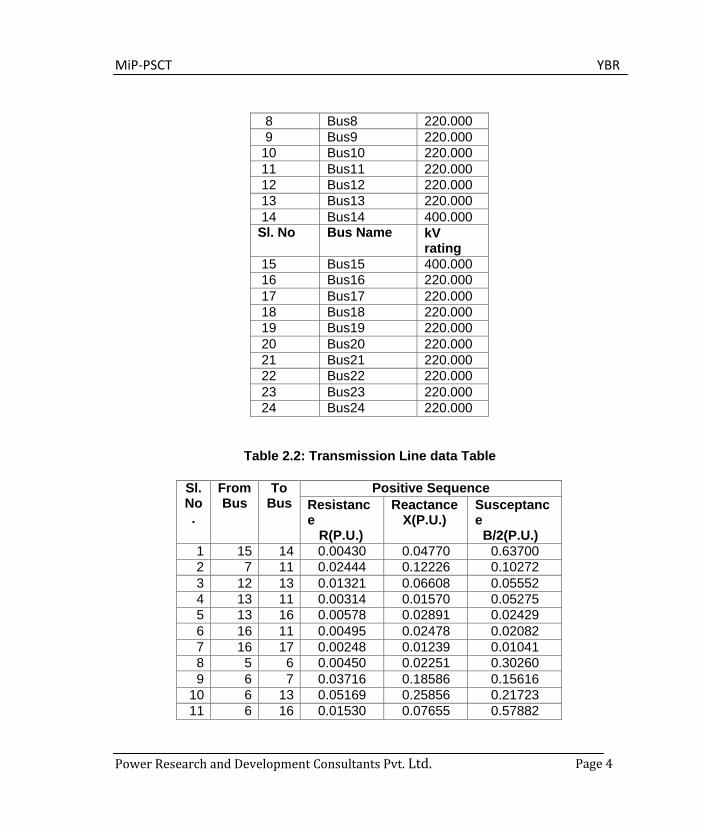
Table 2.1: Bus Data Cable
Sl. No Bus Name kV rating
1 Bus1 11.000 2 Bus2 11.000 3 Bus3 11.000 4 Bus4 11.000 5 Bus5 220.000 6 Bus6 220.000 7 Bus7 220.000
MiP-PSCT YBR
Power Research and Development Consultants Pvt. Ltd. Page 4
8 Bus8 220.000 9 Bus9 220.000
10 Bus10 220.000 11 Bus11 220.000 12 Bus12 220.000 13 Bus13 220.000 14 Bus14 400.000
Sl. No Bus Name kV rating
15 Bus15 400.000 16 Bus16 220.000 17 Bus17 220.000 18 Bus18 220.000 19 Bus19 220.000 20 Bus20 220.000 21 Bus21 220.000 22 Bus22 220.000 23 Bus23 220.000 24 Bus24 220.000
Table 2.2: Transmission Line data Table
Sl. No .
From Bus
To Bus
Positive Sequence Resistanc e
R(P.U.)
Reactance X(P.U.)
Susceptanc e
B/2(P.U.) 1 15 14 0.00430 0.04770 0.63700 2 7 11 0.02444 0.12226 0.10272 3 12 13 0.01321 0.06608 0.05552 4 13 11 0.00314 0.01570 0.05275 5 13 16 0.00578 0.02891 0.02429 6 16 11 0.00495 0.02478 0.02082 7 16 17 0.00248 0.01239 0.01041 8 5 6 0.00450 0.02251 0.30260 9 6 7 0.03716 0.18586 0.15616
10 6 13 0.05169 0.25856 0.21723 11 6 16 0.01530 0.07655 0.57882

MiP-PSCT YBR
Power Research and Development Consultants Pvt. Ltd. Page 5
12 6 8 0.01239 0.06195 0.20822 13 8 9 0.00363 0.01817 0.06107 14 8 10 0.00330 0.01652 0.05552 15 18 19 0.00537 0.02685 0.09022 16 19 5 0.01263 0.06319 0.21237 17 19 20 0.01131 0.05658 0.19016 18 20 24 0.01982 0.09913 0.08328 19 24 5 0.02494 0.12473 0.10480 20 22 23 0.03633 0.18173 0.15269 21 22 20 0.01734 0.08674 0.29149 22 22 21 0.00330 0.01652 0.01388
Table 2.3: Transformer data table
From Bus To Bus Resistance R
Reactance X
MVA Rating
Bus4 Bus15 0.001402 0.02804 475.00 Bus14 Bus11 0.00063 0.01250 475.00 Bus5 Bus1 0.000694 0.013872 704.63 Bus2 Bus18 0.003484 0.06968 156.25 Bus3 Bus22 0.002804 0.05609 237.50
Table 2.4: Generator data table
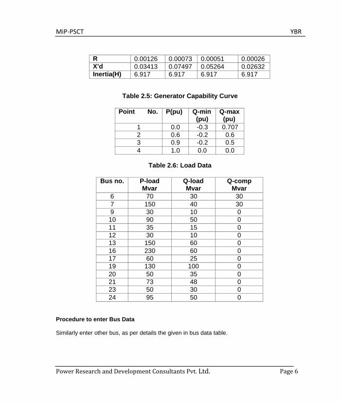
Generator Gen1 Gen2 Gen3 Gen4 P-sch MW 563.7 125.0 190.0 380.0 P-rate MW 712 135 300 420 P-min MW 400 50 120 240 P-max MW 760 140 330 440 V-pu 1.02 1.02 1.02 1.02 Positive sequence R 0.00126 0.00073 0.00051 0.00026 X’d 0.03409 0.07473 0.05247 0.02623 Negative sequence R 0.00126 0.00073 0.00051 0.00026 X’d 0.03409 0.07479 0.05251 0.02626 Zero sequence
MiP-PSCT YBR
Power Research and Development Consultants Pvt. Ltd. Page 6
R 0.00126 0.00073 0.00051 0.00026 X’d 0.03413 0.07497 0.05264 0.02632 Inertia(H) 6.917 6.917 6.917 6.917
Table 2.5: Generator Capability Curve
Point No. P(pu) Q-min
(pu) Q-max
(pu) 1 0.0 -0.3 0.707 2 0.6 -0.2 0.6 3 0.9 -0.2 0.5 4 1.0 0.0 0.0
Table 2.6: Load Data
Bus no. P-load Mvar
Q-load Mvar
Q-comp Mvar
6 70 30 30 7 150 40 30 9 30 10 0 10 90 50 0 11 35 15 0 12 30 10 0 13 150 60 0 16 230 60 0 17 60 25 0 19 130 100 0 20 50 35 0 21 73 48 0 23 50 30 0 24 95 50 0
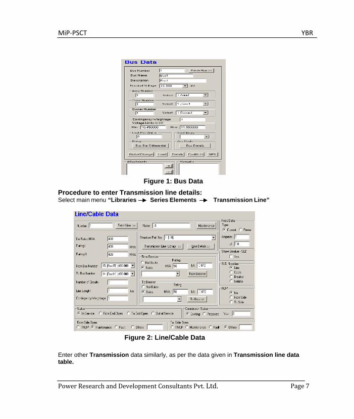
Procedure to enter Bus Data
Similarly enter other bus, as per details the given in bus data table.
MiP-PSCT YBR
Power Research and Development Consultants Pvt. Ltd. Page 7
Figure 1: Bus Data
Procedure to enter Transmission line details: Select main menu “Libraries Series Elements Transmission Line”
Figure 2: Line/Cable Data
Enter other Transmission data similarly, as per the data given in Transmission line data table.
MiP-PSCT YBR
Power Research and Development Consultants Pvt. Ltd. Page 8
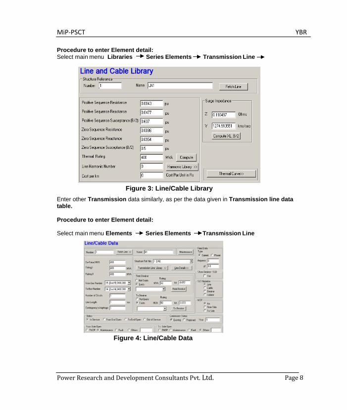
Procedure to enter Element detail: Select main menu Libraries Series Elements Transmission Line
Figure 3: Line/Cable Library Enter other Transmission data similarly, as per the data given in Transmission line data table.
Procedure to enter Element detail:
Select main menu Elements Series Elements Transmission Line
Figure 4: Line/Cable Data
MiP-PSCT YBR
Power Research and Development Consultants Pvt. Ltd. Page 9
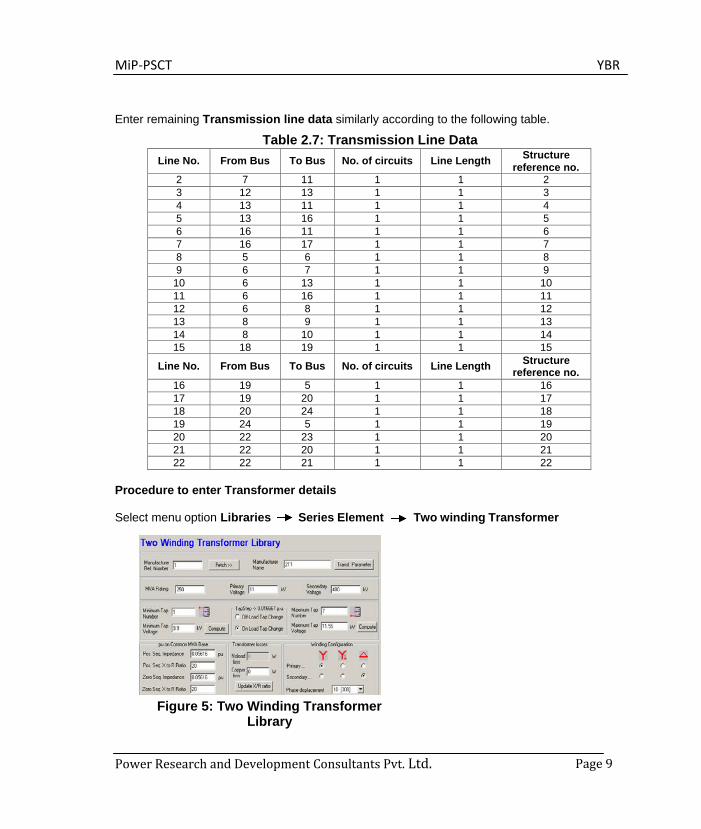
Enter remaining Transmission line data similarly according to the following table.
Table 2.7: Transmission Line Data Line No. From Bus To Bus No. of circuits Line Length Structure
reference no. 2 7 11 1 1 2 3 12 13 1 1 3 4 13 11 1 1 4 5 13 16 1 1 5 6 16 11 1 1 6 7 16 17 1 1 7 8 5 6 1 1 8 9 6 7 1 1 9
10 6 13 1 1 10 11 6 16 1 1 11 12 6 8 1 1 12 13 8 9 1 1 13 14 8 10 1 1 14 15 18 19 1 1 15
Line No. From Bus To Bus No. of circuits Line Length Structure reference no.
16 19 5 1 1 16 17 19 20 1 1 17 18 20 24 1 1 18 19 24 5 1 1 19 20 22 23 1 1 20 21 22 20 1 1 21 22 22 21 1 1 22
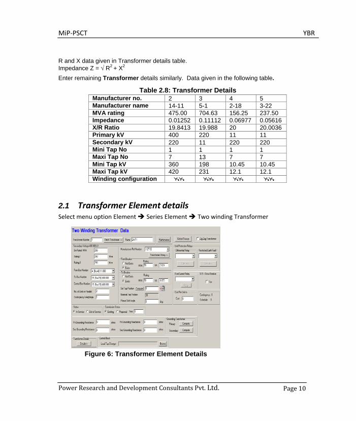
Procedure to enter Transformer details
Select menu option Libraries Series Element Two winding Transformer
Figure 5: Two Winding Transformer Library
MiP-PSCT YBR
Power Research and Development Consultants Pvt. Ltd. Page 10
R and X data given in Transformer details table. Impedance Z = √ R2 + X2
Enter remaining Transformer details similarly. Data given in the following table.
Table 2.8: Transformer Details Manufacturer no. 2 3 4 5 Manufacturer name 14-11 5-1 2-18 3-22 MVA rating 475.00 704.63 156.25 237.50 Impedance 0.01252 0.11112 0.06977 0.05616 X/R Ratio 19.8413 19.988 20 20.0036 Primary kV 400 220 11 11 Secondary kV 220 11 220 220 Mini Tap No 1 1 1 1 Maxi Tap No 7 13 7 7 Mini Tap kV 360 198 10.45 10.45 Maxi Tap kV 420 231 12.1 12.1 Winding configuration
2.1 Transformer Element details Select menu option Element Series Element Two winding Transformer
Figure 6: Transformer Element Details
MiP-PSCT YBR
Power Research and Development Consultants Pvt. Ltd. Page 11
Enter other Transformer details similarly. Details as shown in the following table.
Table 2.9: Transformer Details Transformer no. 2 3 4 5 Transformer name 2T2 2T3 2T4 2T5 From Bus number 14 5 2 3 To Bus number 11 1 18 22 Control Bus number 14 5 18 22 Manufacturer ref number 2 3 4 5 De-Rated MVA 475.00 704.63 156.25 237.50 Nominal Tap 5 9 3 3
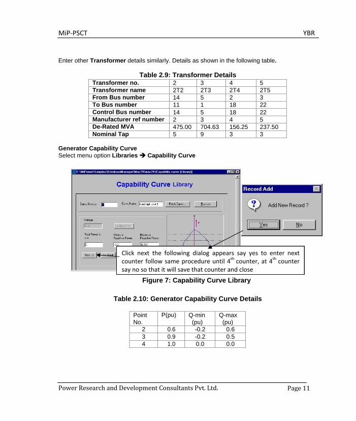
Generator Capability Curve Select menu option Libraries Capability Curve
Figure 7: Capability Curve Library
Table 2.10: Generator Capability Curve Details
Point No.
P(pu) Q-min (pu)
Q-max (pu)
2 0.6 -0.2 0.6 3 0.9 -0.2 0.5 4 1.0 0.0 0.0
Click next the following dialog appears say yes to enter next counter follow same procedure until 4th counter, at 4th counter say no so that it will save that counter and close
MiP-PSCT YBR
Power Research and Development Consultants Pvt. Ltd. Page 12
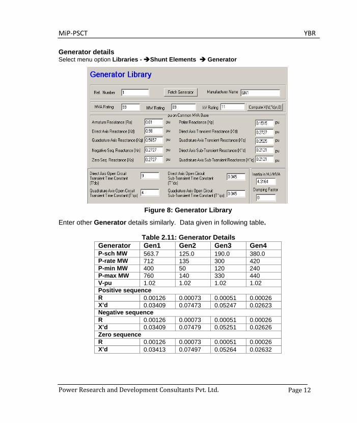
Generator details Select menu option Libraries - Shunt Elements Generator
Figure 8: Generator Library
Enter other Generator details similarly. Data given in following table.
Table 2.11: Generator Details Generator Gen1 Gen2 Gen3 Gen4 P-sch MW 563.7 125.0 190.0 380.0 P-rate MW 712 135 300 420 P-min MW 400 50 120 240 P-max MW 760 140 330 440 V-pu 1.02 1.02 1.02 1.02 Positive sequence R 0.00126 0.00073 0.00051 0.00026 X’d 0.03409 0.07473 0.05247 0.02623 Negative sequence R 0.00126 0.00073 0.00051 0.00026 X’d 0.03409 0.07479 0.05251 0.02626 Zero sequence R 0.00126 0.00073 0.00051 0.00026 X’d 0.03413 0.07497 0.05264 0.02632
MiP-PSCT YBR
Power Research and Development Consultants Pvt. Ltd. Page 13
Inertia(H) 6.917 6.917 6.917 6.917
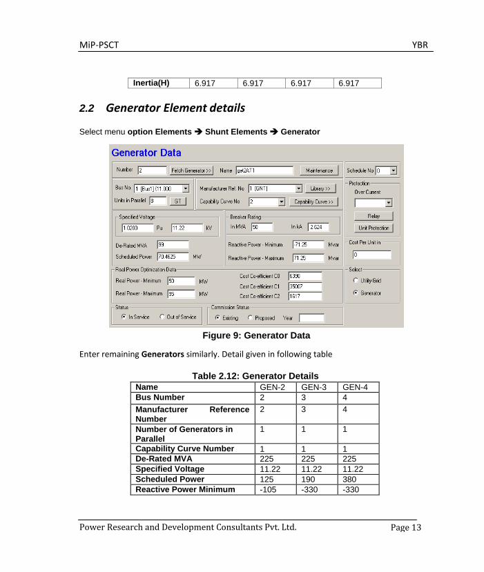
2.2 Generator Element details
Select menu option Elements Shunt Elements Generator
Figure 9: Generator Data
Enter remaining Generators similarly. Detail given in following table
Table 2.12: Generator Details Name GEN-2 GEN-3 GEN-4 Bus Number 2 3 4 Manufacturer Reference Number
2 3 4
Number of Generators in Parallel
1 1 1
Capability Curve Number 1 1 1 De-Rated MVA 225 225 225 Specified Voltage 11.22 11.22 11.22 Scheduled Power 125 190 380 Reactive Power Minimum -105 -330 -330

MiP-PSCT YBR
Power Research and Development Consultants Pvt. Ltd. Page 14
Reactive Power Maximum 95 330 330 Breaker Rating 350 350 350
Load details Select menu option Elements Shunt Elements Load
Figure 10: Load Data
Enter remaining loads similarly. Details given in the following table
Table 2.13: Load Details Bus no. P-load Mvar Q-load Mvar Q-comp Mvar
6 70 30 30 7 150 40 30 9 30 10 0
10 90 50 0 11 35 15 0 12 30 10 0 13 150 60 0 16 230 60 0 17 60 25 0 19 130 100 0 20 50 35 0 21 73 48 0
MiP-PSCT YBR
Power Research and Development Consultants Pvt. Ltd. Page 15
23 50 30 0 24 95 50 0
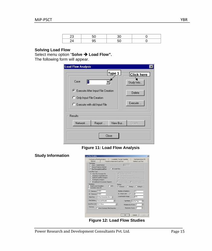
Solving Load Flow Select menu option “Solve Load Flow”. The following form will appear.
Study Information
Figure 11: Load Flow Analysis
Figure 12: Load Flow Studies
Type 1 Click here
MiP-PSCT YBR
Power Research and Development Consultants Pvt. Ltd. Page 16
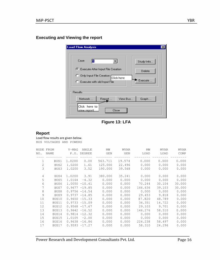
Executing and Viewing the report
Figure 13: LFA
Report Load flow results are given below. BUS VOLTAGES AND POWERS
NODE FROM V-MAG ANGLE MW MVAR MW MVAR MVAR NO. NAME P.U. DEGREE GEN GEN LOAD LOAD COMP ----
1 --------
BUS1 ------ 1.0200
------ 0.00
-------- 563.711
-------- 19.574
-------- 0.000
-------- 0.000
-------- 0.000
2 BUS2 1.0200 1.61 125.000 22.496 0.000 0.000 0.000 3 BUS3 1.0200 3.52 190.000 39.568 0.000 0.000 0.000
4 BUS4 1.0200 3.91 380.000 35.241 0.000 0.000 0.000 5 BUS5 1.0164 -4.32 0.000 0.000 0.000 0.000 0.000 6 BUS6 1.0050 -10.41 0.000 0.000 70.244 30.104 30.000 7 BUS7 0.9677 -19.85 0.000 0.000 146.636 39.103 30.000 8 BUS8 0.9756 -14.54 0.000 0.000 0.000 0.000 0.000 9 BUS9 0.9737 -14.85 0.000 0.000 29.453 9.818 0.000
10 BUS10 0.9650 -15.33 0.000 0.000 87.820 48.789 0.000 11 BUS11 0.9733 -15.09 0.000 0.000 34.351 14.722 0.000 12 BUS12 0.9568 -17.67 0.000 0.000 29.103 9.701 0.000 13 BUS13 0.9642 -16.52 0.000 0.000 146.276 58.510 0.000 14 BUS14 0.9814 -12.32 0.000 0.000 0.000 0.000 0.000 15 BUS15 1.0105 -2.00 0.000 0.000 0.000 0.000 0.000 16 BUS16 0.9638 -16.86 0.000 0.000 224.238 58.497 0.000 17 BUS17 0.9593 -17.27 0.000 0.000 58.310 24.296 0.000
Click here
Click here to view report
MiP-PSCT YBR
Power Research and Development Consultants Pvt. Ltd. Page 17
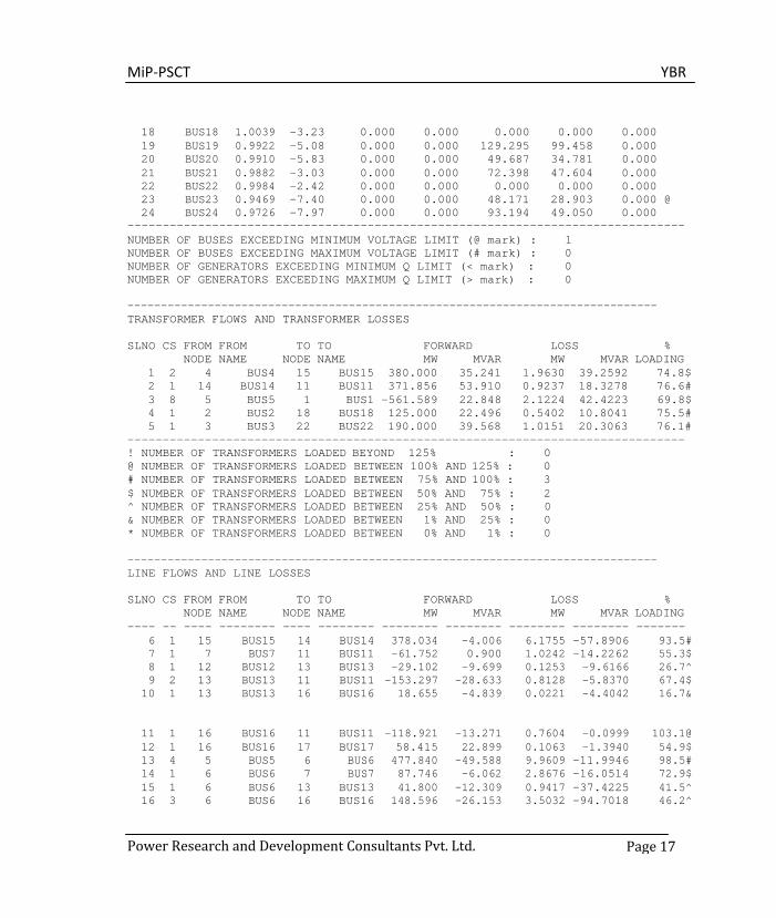
18 BUS18 1.0039 -3.23 0.000 0.000 0.000 0.000 0.000 19 BUS19 0.9922 -5.08 0.000 0.000 129.295 99.458 0.000 20 BUS20 0.9910 -5.83 0.000 0.000 49.687 34.781 0.000 21 BUS21 0.9882 -3.03 0.000 0.000 72.398 47.604 0.000 22 BUS22 0.9984 -2.42 0.000 0.000 0.000 0.000 0.000 23 BUS23 0.9469 -7.40 0.000 0.000 48.171 28.903 0.000 @ 24 BUS24 0.9726 -7.97 0.000 0.000 93.194 49.050 0.000
------------------------------------------------------------------------------- NUMBER OF BUSES EXCEEDING MINIMUM VOLTAGE LIMIT (@ mark) : 1 NUMBER OF BUSES EXCEEDING MAXIMUM VOLTAGE LIMIT (# mark) : 0 NUMBER OF GENERATORS EXCEEDING MINIMUM Q LIMIT (< mark) : 0 NUMBER OF GENERATORS EXCEEDING MAXIMUM Q LIMIT (> mark) : 0
------------------------------------------------------------------------------- TRANSFORMER FLOWS AND TRANSFORMER LOSSES
SLNO CS FROM FROM TO TO FORWARD LOSS %
NODE NAME NODE NAME MW MVAR MW MVAR LOADING 1 2 4 BUS4 15 BUS15 380.000 35.241 1.9630 39.2592 74.8$ 2 1 14 BUS14 11 BUS11 371.856 53.910 0.9237 18.3278 76.6# 3 8 5 BUS5 1 BUS1 -561.589 22.848 2.1224 42.4223 69.8$ 4 1 2 BUS2 18 BUS18 125.000 22.496 0.5402 10.8041 75.5# 5 1 3 BUS3 22 BUS22 190.000 39.568 1.0151 20.3063 76.1#
------------------------------------------------------------------------------- ! NUMBER OF TRANSFORMERS LOADED BEYOND 125% : 0 @ NUMBER OF TRANSFORMERS LOADED BETWEEN 100% AND 125% : 0 # NUMBER OF TRANSFORMERS LOADED BETWEEN 75% AND 100% : 3 $ NUMBER OF TRANSFORMERS LOADED BETWEEN 50% AND 75% : 2 ^ NUMBER OF TRANSFORMERS LOADED BETWEEN 25% AND 50% : 0 & NUMBER OF TRANSFORMERS LOADED BETWEEN 1% AND 25% : 0 * NUMBER OF TRANSFORMERS LOADED BETWEEN 0% AND 1% : 0
------------------------------------------------------------------------------- LINE FLOWS AND LINE LOSSES
SLNO CS FROM FROM TO TO FORWARD LOSS %
NODE NAME NODE NAME MW MVAR MW MVAR LOADING ---- -- ---- -------- ---- -------- -------- -------- -------- -------- -------
6 1 15 BUS15 14 BUS14 378.034 -4.006 6.1755 -57.8906 93.5# 7 1 7 BUS7 11 BUS11 -61.752 0.900 1.0242 -14.2262 55.3$ 8 1 12 BUS12 13 BUS13 -29.102 -9.699 0.1253 -9.6166 26.7^ 9 2 13 BUS13 11 BUS11 -153.297 -28.633 0.8128 -5.8370 67.4$
10 1 13 BUS13 16 BUS16 18.655 -4.839 0.0221 -4.4042 16.7&
11
1
16
BUS16
11
BUS11
-118.921
-13.271
0.7604
-0.0999
103.1@
12 1 16 BUS16 17 BUS17 58.415 22.899 0.1063 -1.3940 54.9$ 13 4 5 BUS5 6 BUS6 477.840 -49.588 9.9609 -11.9946 98.5# 14 1 6 BUS6 7 BUS7 87.746 -6.062 2.8676 -16.0514 72.9$ 15 1 6 BUS6 13 BUS13 41.800 -12.309 0.9417 -37.4225 41.5^ 16 3 6 BUS6 16 BUS16 148.596 -26.153 3.5032 -94.7018 46.2^
MiP-PSCT YBR
Power Research and Development Consultants Pvt. Ltd. Page 18
17 2 6 BUS6 8 BUS8 119.493 6.806 1.8467 -31.6140 52.9$ 18 2 8 BUS8 9 BUS9 29.486 -1.617 0.0338 -11.4338 13.3& 19 2 8 BUS8 10 BUS10 88.160 40.038 0.3407 -8.7495 43.4^ 20 2 18 BUS18 19 BUS19 124.460 11.692 0.8483 -13.7340 53.0$ 21 2 19 BUS19 5 BUS5 -27.772 -53.132 0.2321 -41.6860 25.2^ 22 2 19 BUS19 20 BUS20 22.088 -20.899 0.0566 -37.1160 12.8& 23 1 20 BUS20 24 BUS24 38.691 3.175 0.3281 -14.4170 36.2^ 24 1 24 BUS24 5 BUS5 -54.831 -31.457 0.9149 -16.1647 54.2$ 25 1 22 BUS22 23 BUS23 49.205 5.164 1.0339 -23.7399 49.4^ 26 2 22 BUS22 20 BUS20 67.132 -32.016 0.7855 -53.7550 31.0^ 27 1 22 BUS22 21 BUS21 72.648 46.114 0.2494 -1.4903 73.1$
------------------------------------------------------------------------------- ! NUMBER OF LINES LOADED BEYOND 125% : 0 @ NUMBER OF LINES LOADED BETWEEN 100% AND 125% : 1 # NUMBER OF LINES LOADED BETWEEN 75% AND 100% : 2 $ NUMBER OF LINES LOADED BETWEEN 50% AND 75% : 8 ^ NUMBER OF LINES LOADED BETWEEN 25% AND 50% : 8 & NUMBER OF LINES LOADED BETWEEN 1% AND 25% : 3 * NUMBER OF LINES LOADED BETWEEN 0% AND 1% : 0 -------------------------------------------------------------------------------
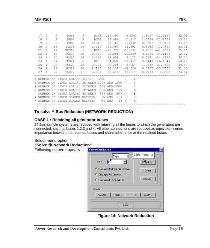
To solve Y-Bus Reduction (NETWORK REDUCTION)
CASE 1 : Retaining all generator buses 24 Bus sample systems are reduced with retaining all the buses to which the generators are connected, such as buses 1,2,3 and 4. All other connections are reduced as equivalent series impedance between the retained buses and shunt admittance at the retained buses.
Select menu option “Solve Network Reduction” Following screen appears
Figure 14: Network Reduction
Type 1 Click here to

MiP-PSCT YBR
Power Research and Development Consultants Pvt. Ltd. Page 19
Study Information Following screen shows study information for Case 1. Similarly select buses 1, 2, 3, and 4.
Figure 15: Network Reduction(zone Reduction & Bus reduction) Click OK after entering information. Execute Network Reduction. Click Report button to view the report.
Network Reduction Report for case 1
NETWORK REDUCTION CASE NO : 11 CONTINGENCY : 0 SCHEDULE NO : 0 CONTINGENCY NAME : Base Case
------------------------------------------------------------------------------- %% TOTAL NUMBER OF BUSES : 24 ACTUAL NUMBER OF BUSES : 24 NUMBER OF 2 WIND. TRANSFORMERS : 5 NUMBER OF 3 WIND. TRANSFORMERS : 0 NUMBER OF TRANSMISSION LINES : 22 NUMBER OF SERIES REACTORS : 0 NUMBER OF SERIES CAPACITORS : 0 NUMBER OF BUS COUPLERS : 0 NUMBER OF SHUNT REACTORS : 0 NUMBER OF SHUNT CAPACITORS : 0
Select only generator buses
Give Network name

MiP-PSCT YBR
Power Research and Development Consultants Pvt. Ltd. Page 20
NUMBER OF SHUNT IMPEDANCES : 0 NUMBER OF GENERATORS : 4 NUMBER OF LOADS : 14 NUMBER OF FILTERS : 0 NUMBER OF HVDC CONVERTORS : 0
-------------------------------------------------------------------------------
NUMBER OF ZONES : 2
PRINT OPTION : 3 (BOTH DATA AND RESULTS PRINT) BASE MVA : 100.000 NOMINAL SYSTEM FREQUENCY: 50.000 PREFAULT VOLTAGE OPTION : 1 (READ FROM THE FILE) ZONE NUMBER RETAINED : 0 ZBUS PRINT OPTION : 0 YBUS REDUCTION OPTION : 1 (NETWORK REDUCTION) -------------------------------------------------------------------------------
4 1 2 3 4
------------------------------------------------------------------------------- CIRCUIT BREAKER RESISTANCE (PU) : 0.000000 CIRCUIT BREAKER REACTANCE (PU) : 0.000100 TRANSFORMER R/X RATIO : 0.050000 TRANSFORMER ZERO SEQUENCE IMPEDANCE MULT FACTOR : 0.900000
NUMBER OF TRANSMISSION VOLTAGE LEVELS : 3 TRANSMISSION LINE VOLTAGE - KV :
11.000000
TRANSMISSION LINE ZERO SEQUENCE RES. MULT. FACTOR : 0.000000 TRANSMISSION LINE ZERO SEQUENCE REA. MULT. FACTOR : 0.000000 TRANSMISSION LINE ZERO SEQUENCE ADM. MULT. FACTOR : 0.000000 TRANSMISSION LINE VOLTAGE - KV : 220.000000 TRANSMISSION LINE ZERO SEQUENCE RES. MULT. FACTOR : 2.500000 TRANSMISSION LINE ZERO SEQUENCE REA. MULT. FACTOR : 2.500000 TRANSMISSION LINE ZERO SEQUENCE ADM. MULT. FACTOR : 0.025000 TRANSMISSION LINE VOLTAGE - KV : 400.000000 TRANSMISSION LINE ZERO SEQUENCE RES. MULT. FACTOR : 2.500000 TRANSMISSION LINE ZERO SEQUENCE REA. MULT. FACTOR : 2.500000 TRANSMISSION LINE ZERO SEQUENCE ADM. MULT. FACTOR : 0.025000
GENERATOR NEGATIVE SEQUENCE RESISTANCE MULT. FACTOR : 0.175000 GENERATOR NEGATIVE SEQUENCE REACTANCE MULT. FACTOR : 0.175000 GENERATOR ZERO SEQUENCE RESISTANCE MULT. FACTOR : 0.037500 GENERATOR ZERO SEQUENCE REACTANCE MULT. FACTOR : 0.037500 LOAD NEGATIVE SEQUENCE IMPEDANCE MULT. FACTOR : 0.810000 LOAD ZERO SEQUENCE IMPEDANCE MULT. FACTOR : 1.600000 SERIES REACTOR ZERO SEQUENCE IMPEDANCE MULT. FACTOR : 1.000000 SHUNT REACTOR ZERO SEQUENCE IMPEDANCE MULT. FACTOR : 0.625000 ------------------------------------------------------------------------------- -------------------------------------------------------------------------------
MiP-PSCT YBR
Power Research and Development Consultants Pvt. Ltd. Page 21
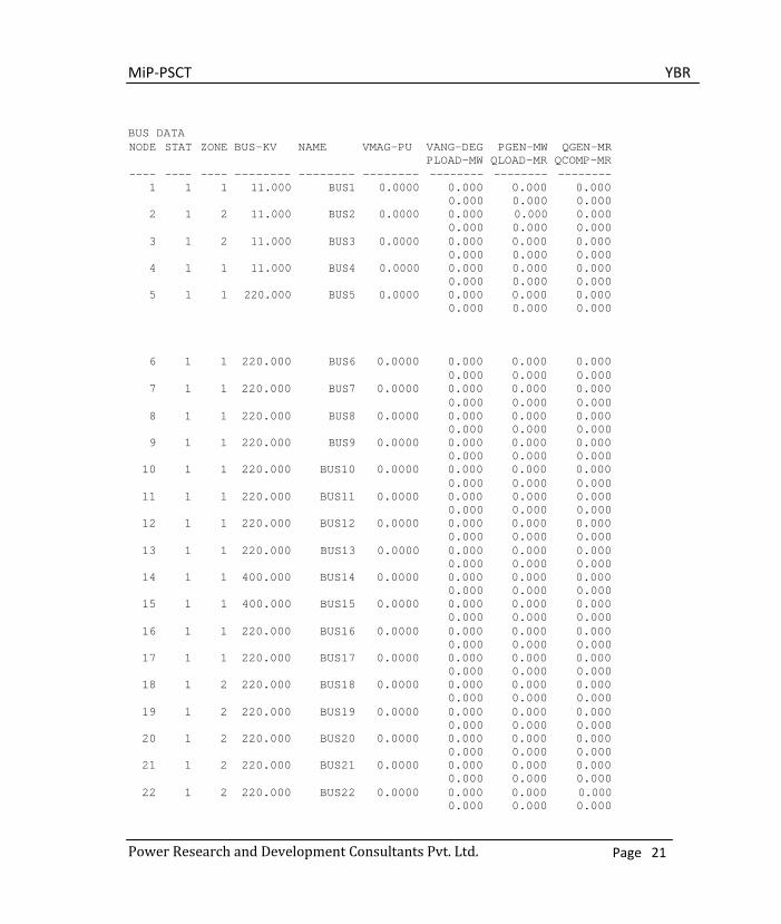
BUS DATA NODE STAT ZONE BUS-KV NAME VMAG-PU VANG-DEG
PLOAD-MW PGEN-MW
QLOAD-MR QGEN-MR
QCOMP-MR ---- ---- ---- -------- -------- -------- -------- -------- --------
1 1 1 11.000 BUS1 0.0000 0.000 0.000 0.000
0.000 0.000 0.000 2 1 2 11.000 BUS2 0.0000 0.000 0.000 0.000
0.000 0.000 0.000 3 1 2 11.000 BUS3 0.0000 0.000 0.000 0.000
0.000 0.000 0.000 4 1 1 11.000 BUS4 0.0000 0.000 0.000 0.000
0.000 0.000 0.000 5 1 1 220.000 BUS5 0.0000 0.000 0.000 0.000
0.000 0.000 0.000
6 1 1 220.000 BUS6 0.0000 0.000 0.000 0.000
0.000 0.000 0.000 7 1 1 220.000 BUS7 0.0000 0.000 0.000 0.000
0.000 0.000 0.000 8 1 1 220.000 BUS8 0.0000 0.000 0.000 0.000
0.000 0.000 0.000 9 1 1 220.000 BUS9 0.0000 0.000 0.000 0.000
0.000 0.000 0.000 10 1 1 220.000 BUS10 0.0000 0.000 0.000 0.000
0.000 0.000 0.000 11 1 1 220.000 BUS11 0.0000 0.000 0.000 0.000
0.000 0.000 0.000 12 1 1 220.000 BUS12 0.0000 0.000 0.000 0.000
0.000 0.000 0.000 13 1 1 220.000 BUS13 0.0000 0.000 0.000 0.000
0.000 0.000 0.000 14 1 1 400.000 BUS14 0.0000 0.000 0.000 0.000
0.000 0.000 0.000 15 1 1 400.000 BUS15 0.0000 0.000 0.000 0.000
0.000 0.000 0.000 16 1 1 220.000 BUS16 0.0000 0.000 0.000 0.000
0.000 0.000 0.000 17 1 1 220.000 BUS17 0.0000 0.000 0.000 0.000
0.000 0.000 0.000 18 1 2 220.000 BUS18 0.0000 0.000 0.000 0.000
0.000 0.000 0.000 19 1 2 220.000 BUS19 0.0000 0.000 0.000 0.000
0.000 0.000 0.000 20 1 2 220.000 BUS20 0.0000 0.000 0.000 0.000
0.000 0.000 0.000 21 1 2 220.000 BUS21 0.0000 0.000 0.000 0.000
0.000 0.000 0.000 22 1 2 220.000 BUS22 0.0000 0.000 0.000 0.000
0.000 0.000 0.000
MiP-PSCT YBR
Power Research and Development Consultants Pvt. Ltd. Page 22
23 1 2 220.000 BUS23 0.0000 0.000 0.000 0.000
0.000 0.000 0.000 24 1 2 220.000 BUS24 0.0000 0.000 0.000 0.000
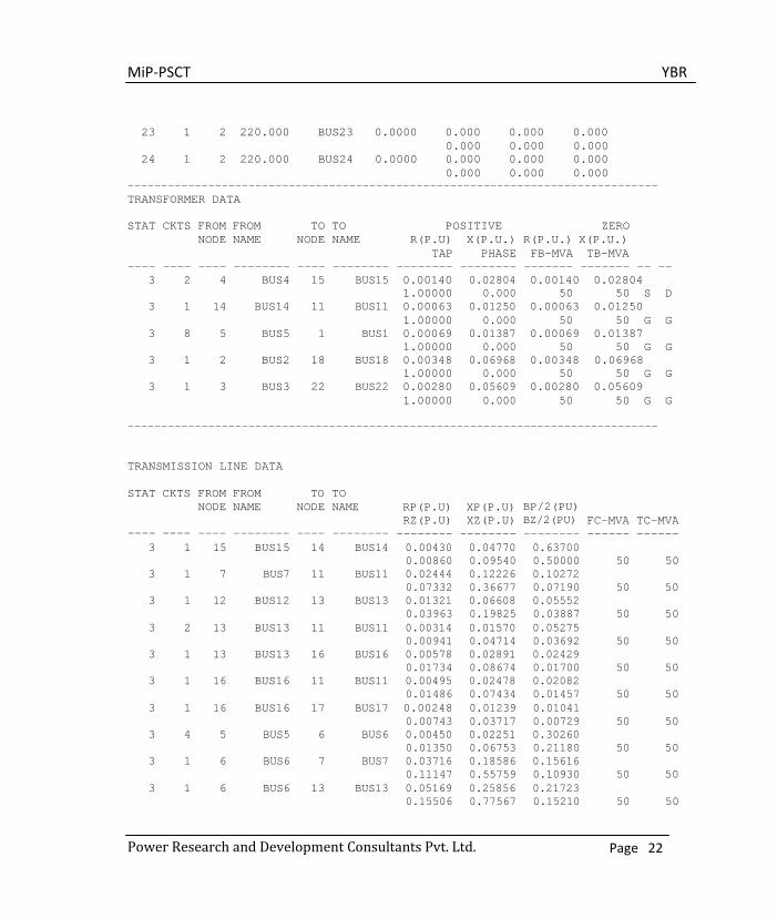
0.000 0.000 0.000 ------------------------------------------------------------------------------- TRANSFORMER DATA
STAT CKTS FROM FROM TO TO POSITIVE ZERO
NODE NAME NODE NAME R(P.U) X(P.U.) R(P.U.) X(P.U.) TAP PHASE FB-MVA TB-MVA
---- ---- ---- -------- ---- -------- -------- -------- ------- ------- -- -- 3 2 4 BUS4 15 BUS15 0.00140 0.02804 0.00140 0.02804 1.00000 0.000 50 50 S D 3 1 14 BUS14 11 BUS11 0.00063 0.01250 0.00063 0.01250 1.00000 0.000 50 50 G G 3 8 5 BUS5 1 BUS1 0.00069 0.01387 0.00069 0.01387 1.00000 0.000 50 50 G G 3 1 2 BUS2 18 BUS18 0.00348 0.06968 0.00348 0.06968 1.00000 0.000 50 50 G G 3 1 3 BUS3 22 BUS22 0.00280 0.05609 0.00280 0.05609 1.00000 0.000 50 50 G G
-------------------------------------------------------------------------------
TRANSMISSION LINE DATA
STAT ----
CKTS ----
FROM NODE ----
FROM NAME --------
TO NODE ----
TO NAME --------
RP(P.U) RZ(P.U) --------
XP(P.U) XZ(P.U) --------
BP/2(PU) BZ/2(PU) --------
FC-MVA ------
TC-MVA ------
3 1 15 BUS15 14 BUS14 0.00430 0.04770 0.63700 0.00860 0.09540 0.50000 50 50
3 1 7 BUS7 11 BUS11 0.02444 0.12226 0.10272 0.07332 0.36677 0.07190 50 50
3 1 12 BUS12 13 BUS13 0.01321 0.06608 0.05552 0.03963 0.19825 0.03887 50 50
3 2 13 BUS13 11 BUS11 0.00314 0.01570 0.05275 0.00941 0.04714 0.03692 50 50
3 1 13 BUS13 16 BUS16 0.00578 0.02891 0.02429 0.01734 0.08674 0.01700 50 50
3 1 16 BUS16 11 BUS11 0.00495 0.02478 0.02082 0.01486 0.07434 0.01457 50 50
3 1 16 BUS16 17 BUS17 0.00248 0.01239 0.01041 0.00743 0.03717 0.00729 50 50
3 4 5 BUS5 6 BUS6 0.00450 0.02251 0.30260 0.01350 0.06753 0.21180 50 50
3 1 6 BUS6 7 BUS7 0.03716 0.18586 0.15616 0.11147 0.55759 0.10930 50 50
3 1 6 BUS6 13 BUS13 0.05169 0.25856 0.21723 0.15506 0.77567 0.15210 50 50
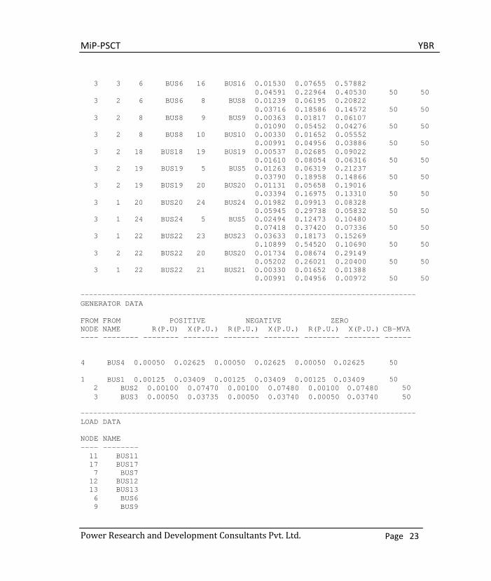
MiP-PSCT YBR
Power Research and Development Consultants Pvt. Ltd. Page 23
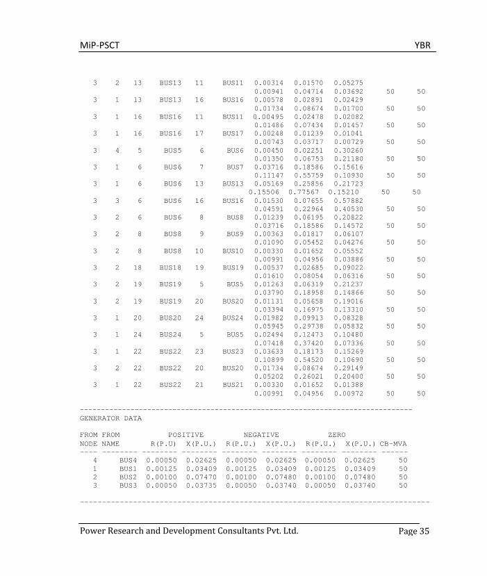
3 3 6 BUS6 16 BUS16 0.01530 0.07655 0.57882 0.04591 0.22964 0.40530 50 50 3 2 6 BUS6 8 BUS8 0.01239 0.06195 0.20822 0.03716 0.18586 0.14572 50 50 3 2 8 BUS8 9 BUS9 0.00363 0.01817 0.06107 0.01090 0.05452 0.04276 50 50 3 2 8 BUS8 10 BUS10 0.00330 0.01652 0.05552 0.00991 0.04956 0.03886 50 50 3 2 18 BUS18 19 BUS19 0.00537 0.02685 0.09022 0.01610 0.08054 0.06316 50 50 3 2 19 BUS19 5 BUS5 0.01263 0.06319 0.21237 0.03790 0.18958 0.14866 50 50 3 2 19 BUS19 20 BUS20 0.01131 0.05658 0.19016 0.03394 0.16975 0.13310 50 50 3 1 20 BUS20 24 BUS24 0.01982 0.09913 0.08328 0.05945 0.29738 0.05832 50 50 3 1 24 BUS24 5 BUS5 0.02494 0.12473 0.10480 0.07418 0.37420 0.07336 50 50 3 1 22 BUS22 23 BUS23 0.03633 0.18173 0.15269 0.10899 0.54520 0.10690 50 50 3 2 22 BUS22 20 BUS20 0.01734 0.08674 0.29149 0.05202 0.26021 0.20400 50 50 3 1 22 BUS22 21 BUS21 0.00330 0.01652 0.01388 0.00991 0.04956 0.00972 50 50
------------------------------------------------------------------------------- GENERATOR DATA
FROM FROM POSITIVE NEGATIVE ZERO NODE NAME R(P.U) X(P.U.) R(P.U.) X(P.U.) R(P.U.) X(P.U.) CB-MVA ---- -------- -------- -------- -------- -------- -------- -------- ------
4 BUS4 0.00050 0.02625 0.00050 0.02625 0.00050 0.02625 50
1 2
BUS1 0.00125 0.03409 0.00125 0.03409 0.00125 0.03409 BUS2 0.00100 0.07470 0.00100 0.07480 0.00100 0.07480
50 50
3 BUS3 0.00050 0.03735 0.00050 0.03740 0.00050 0.03740 50
------------------------------------------------------------------------------- LOAD DATA
NODE NAME ---- -------- 11 BUS11 17 BUS17 7 BUS7 12 BUS12 13 BUS13 6 BUS6 9 BUS9

MiP-PSCT YBR
Power Research and Development Consultants Pvt. Ltd. Page 24
10 BUS10 20 BUS20 23 BUS23 21 BUS21 16 BUS16 19 BUS19 24 BUS24
Number of reduced buses: 4 Reduced bus array:
1 2 3 4 ------------------------------------------------------------------------------- ------------------------------------------------------------------------------ POSITIVE SEQUENCE ADMITTANCE MATRIX ELEMENTS FOR THE GIVEN SYSTEM ------------------------------------------------------------------------------ ROW NO COLUMN NO REAL IMAGINARY ------ --------- ---------- ----------
1 1 1.57674 -9.97533 1 2 -0.55642 5.07156 1 3 -0.48112 3.10001 1 4 -0.54116 5.82485 2 1 -0.55642 5.07156 2 2 0.80100 -6.49955 2 3 -0.16692 1.67456 2 4 -0.08116 0.47480 3 1 -0.48112 3.10001 3 2 -0.16692 1.67456 3 3 0.71590 -4.07908 3 4 -0.06290 0.28943 4 1 -0.54116 5.82485 4 2 -0.08116 0.47480 4 3 -0.06290 0.28943 4 4 0.77828 -4.28315
------------------------------------------------------------------------------ ------------------------------------------------------------------------------ NEGATIVE SEQUENCE ADMITTANCE MATRIX ELEMENTS FOR THE GIVEN SYSTEM ------------------------------------------------------------------------------ ROW NO ------
COLUMN NO ---------
REAL ----------
IMAGINARY ----------
1 1 1.57674 -9.97533
1
2
-0.55642
5.07156 1 3 -0.48112 3.10001 1 4 -0.54116 5.82485 2 1 -0.55642 5.07156 2 2 0.80100 -6.49955 2 3 -0.16692 1.67456 2 4 -0.08116 0.47480 3 1 -0.48112 3.10001 3 2 -0.16692 1.67456 3 3 0.71590 -4.07908

MiP-PSCT YBR
Power Research and Development Consultants Pvt. Ltd. Page 25
3 4 -0.06290 0.28943 4 1 -0.54116 5.82485 4 2 -0.08116 0.47480 4 3 -0.06290 0.28943 4 4 0.77828 -4.28315
------------------------------------------------------------------------------ ------------------------------------------------------------------------------ ZERO SEQUENCE ADMITTANCE MATRIX ELEMENTS FOR THE GIVEN SYSTEM ------------------------------------------------------------------------------ ROW NO COLUMN NO REAL IMAGINARY ------ --------- ---------- ----------
1 1 1.85798 2.79557 1 2 -0.38654 2.97755 1 3 -0.20996 1.32202 1 4 -0.00000 -0.00000 2 1 -0.38654 2.97755 2 2 0.54724 -3.25450 2 3 -0.12810 0.93226 2 4 -0.00000 -0.00000 3 1 -0.20996 1.32202 3 2 -0.12810 0.93226 3 3 0.35595 -1.48148 3 4 -0.00000 -0.00000 4 1 -0.00000 -0.00000 4 2 -0.00000 -0.00000 4 3 -0.00000 -0.00000 4 4 0.00000 0.00000
------------------------------------------------------------------------------ ------------------------------------------------------------------------------- RETAINED ZONE : 0 NUMBER OF SERIES ELEMENTS IN THE REDUCED ZONES : 6 SERIES CONNECTIONS SLNO FROM NAME TO NAME RP XP BP/2 RZ XZ BZ/2 ---- ---- -------- ---- -------- -------- -------- ---- -------- -------- ----
1 1 BUS1 2 BUS2 0.021376 0.194833 0.0 0.042877 0.330280 0.0 2 1 BUS1 3 BUS3 0.048886 0.314993 0.0 0.117178 0.737806 0.0 3 1 BUS1 4 BUS4 0.015813 0.170209 0.0 0.000000 9999.000 0.0 4 2 BUS2 3 BUS3 0.058939 0.591298 0.0 0.144667 1.052787 0.0 5 2 BUS2 4 BUS4 0.349794 2.046351 0.0 0.000000 9999.000 0.0 6 3 BUS3 4 BUS4 0.717003 3.299303 0.0 0.000000 9999.000 0.0
------------------------------------------------------------------------------- NUMBER OF SHUNT ELEMENTS IN THE REDUCED ZONES : 4 SHUNT CONNECTIONS IN (G+JB) FORMAT - PU SLNO FROM NAME GP BP GZ BZ ---- ---- -------- -------- -------- -------- --------
1 1 BUS1 -0.00196 4.02109 1.26147 7.09515 2 2 BUS2 -0.00350 0.72137 0.03259 0.65530 3 3 BUS3 0.00497 0.98491 0.01788 0.77280 4 4 BUS4 0.09307 2.30593 -0.00000 -0.00000
-------------------------------------------------------------------------------
MiP-PSCT YBR
Power Research and Development Consultants Pvt. Ltd. Page 26
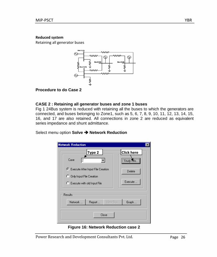
Reduced system Retaining all generator buses
Procedure to do Case 2
CASE 2 : Retaining all generator buses and zone 1 buses Fig 1 24Bus system is reduced with retaining all the buses to which the generators are connected, and buses belonging to Zone1, such as 5, 6, 7, 8, 9, 10, 11, 12, 13, 14, 15, 16, and 17 are also retained. All connections in zone 2 are reduced as equivalent series impedance and shunt admittance.
Select menu option Solve Network Reduction
Figure 16: Network Reduction case 2
Type 2 Click here

MiP-PSCT YBR
Power Research and Development Consultants Pvt. Ltd. Page 27
Study Information Following study information screen will open. In that select zone 1 buses and all
generator buses.
Figure 17: Study information
Executing and viewing the report
Figure 18: Executing and viewing the report
Select buses here
Give network
Click here
After execution, click here to view
MiP-PSCT YBR
Power Research and Development Consultants Pvt. Ltd. Page 28
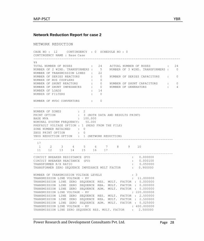
Network Reduction Report for case 2
NETWORK REDUCTION
CASE NO : 12 CONTINGENCY : 0 SCHEDULE NO : 0 CONTINGENCY NAME : Base Case ------------------------------------------------------------------------------- %% TOTAL NUMBER OF BUSES : 24 ACTUAL NUMBER OF BUSES : 24 NUMBER OF 2 WIND. TRANSFORMERS : 5 NUMBER OF 3 WIND. TRANSFORMERS : 0 NUMBER OF TRANSMISSION LINES : 22 NUMBER OF SERIES REACTORS : 0 NUMBER OF SERIES CAPACITORS : 0 NUMBER OF BUS COUPLERS : 0 NUMBER OF SHUNT REACTORS : 0 NUMBER OF SHUNT CAPACITORS : 0 NUMBER OF SHUNT IMPEDANCES : 0 NUMBER OF GENERATORS : 4 NUMBER OF LOADS : 14 NUMBER OF FILTERS : 0 NUMBER OF HVDC CONVERTORS : 0
------------------------------------------------------------------------------- NUMBER OF ZONES : 2 PRINT OPTION : 3 (BOTH DATA AND RESULTS PRINT) BASE MVA : 100.000 NOMINAL SYSTEM FREQUENCY: 50.000 PREFAULT VOLTAGE OPTION : 1 (READ FROM THE FILE) ZONE NUMBER RETAINED : 0 ZBUS PRINT OPTION : 0 YBUS REDUCTION OPTION : 1 (NETWORK REDUCTION) ------------------------------------------------------------------------------- 17 1 2 3 4 5 6 7 8 9 10
11 12 13 14 15 16 17 ------------------------------------------------------------------------------- CIRCUIT BREAKER RESISTANCE (PU) : 0.000000 CIRCUIT BREAKER REACTANCE (PU) : 0.000100 TRANSFORMER R/X RATIO : 0.050000 TRANSFORMER ZERO SEQUENCE IMPEDANCE MULT FACTOR : 0.900000
NUMBER OF TRANSMISSION VOLTAGE LEVELS : 3 TRANSMISSION LINE VOLTAGE - KV : 11.000000 TRANSMISSION LINE ZERO SEQUENCE RES. MULT. FACTOR : 0.000000 TRANSMISSION LINE ZERO SEQUENCE REA. MULT. FACTOR : 0.000000 TRANSMISSION LINE ZERO SEQUENCE ADM. MULT. FACTOR : 0.000000 TRANSMISSION LINE VOLTAGE - KV : 220.000000 TRANSMISSION LINE ZERO SEQUENCE RES. MULT. FACTOR : 2.500000 TRANSMISSION LINE ZERO SEQUENCE REA. MULT. FACTOR : 2.500000 TRANSMISSION LINE ZERO SEQUENCE ADM. MULT. FACTOR : 0.025000 TRANSMISSION LINE VOLTAGE - KV : 400.000000 TRANSMISSION LINE ZERO SEQUENCE RES. MULT. FACTOR : 2.500000

MiP-PSCT YBR
Power Research and Development Consultants Pvt. Ltd. Page 29
TRANSMISSION LINE ZERO SEQUENCE REA. MULT. FACTOR : 2.500000 TRANSMISSION LINE ZERO SEQUENCE ADM. MULT. FACTOR : 0.025000 GENERATOR NEGATIVE SEQUENCE RESISTANCE MULT. FACTOR : 0.175000 GENERATOR NEGATIVE SEQUENCE REACTANCE MULT. FACTOR : 0.175000 GENERATOR ZERO SEQUENCE RESISTANCE MULT. FACTOR : 0.037500 GENERATOR ZERO SEQUENCE REACTANCE MULT. FACTOR : 0.037500 LOAD NEGATIVE SEQUENCE IMPEDANCE MULT. FACTOR : 0.810000 LOAD ZERO SEQUENCE IMPEDANCE MULT. FACTOR : 1.600000 SERIES REACTOR ZERO SEQUENCE IMPEDANCE MULT. FACTOR : 1.000000 SHUNT REACTOR ZERO SEQUENCE IMPEDANCE MULT. FACTOR : 0.625000 ------------------------------------------------------------------ Number of reduced buses : 17 Reduced bus array :
1 2 3 4 5 6 7 8 9 10 11 12 13 14 15 16 17
------------------------------------------------------------------------------- RETAINED ZONE : 0 NUMBER OF SERIES ELEMENTS IN THE REDUCED ZONES : 3 SERIES CONNECTIONS SLNO FROM NAME TO NAME RP XP BP/2 RZ XZ BZ/2 ---- ---- -------- ---- -------- -------- -------- ---- -------- -------- ----
1 2 BUS2 3 BUS3 0.052959 0.698685 0.0 0.144805 1.117180 0.0 2 2 BUS2 5 BUS5 0.021307 0.167338 0.0 0.053638 0.341475 0.0 3 3 BUS3 5 BUS5 0.046777 0.270327 0.0 0.142020 0.762220 0.0
------------------------------------------------------------------------------- NUMBER OF SHUNT ELEMENTS IN THE REDUCED ZONES : 3 SHUNT CONNECTIONS IN (G+JB) FORMAT - PU SLNO FROM NAME GP BP GZ BZ ---- ---- -------- -------- -------- -------- --------
1 2 BUS2 0.02202 0.39125 0.01230 0.36643 2 3 BUS3 0.02972 0.78283 0.01249 0.64382 3 5 BUS5 -0.03960 1.19377 -0.01182 0.66770
-------------------------------------------------------------------------------
MiP-PSCT YBR
Power Research and Development Consultants Pvt. Ltd. Page 30
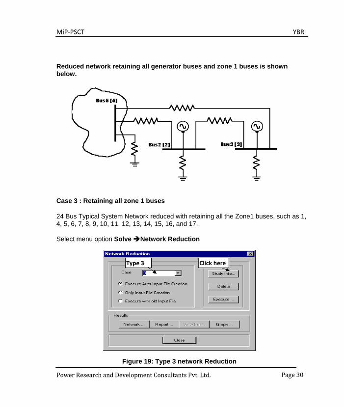
Reduced network retaining all generator buses and zone 1 buses is shown below.
Case 3 : Retaining all zone 1 buses
24 Bus Typical System Network reduced with retaining all the Zone1 buses, such as 1, 4, 5, 6, 7, 8, 9, 10, 11, 12, 13, 14, 15, 16, and 17.
Select menu option Solve Network Reduction
Figure 19: Type 3 network Reduction
Type 3 Click here
MiP-PSCT YBR
Power Research and Development Consultants Pvt. Ltd. Page 31
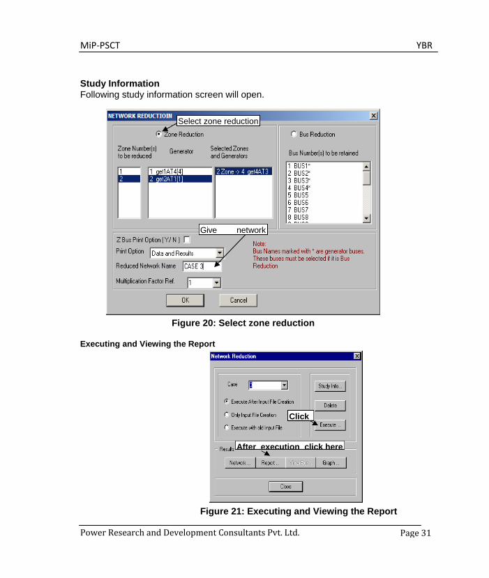
Study Information Following study information screen will open.
Figure 20: Select zone reduction
Executing and Viewing the Report
Figure 21: Executing and Viewing the Report
Select zone reduction
Give network
Click
After execution click here
MiP-PSCT YBR
Power Research and Development Consultants Pvt. Ltd. Page 32
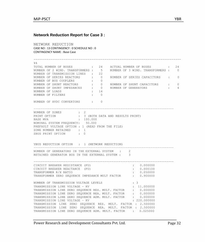
Network Reduction Report for Case 3 :
NETWORK REDUCTION CASE NO : 13 CONTINGENCY : 0 SCHEDULE NO : 0 CONTINGENCY NAME : Base Case
------------------------------------------------------------------------------- %% TOTAL NUMBER OF BUSES : 24 ACTUAL NUMBER OF BUSES : 24 NUMBER OF 2 WIND. TRANSFORMERS : 5 NUMBER OF 3 WIND. TRANSFORMERS : 0 NUMBER OF TRANSMISSION LINES : 22 NUMBER OF SERIES REACTORS : 0 NUMBER OF SERIES CAPACITORS : 0 NUMBER OF BUS COUPLERS : 0 NUMBER OF SHUNT REACTORS : 0 NUMBER OF SHUNT CAPACITORS : 0 NUMBER OF SHUNT IMPEDANCES : 0 NUMBER OF GENERATORS : 4 NUMBER OF LOADS : 14 NUMBER OF FILTERS : 0 NUMBER OF HVDC CONVERTORS : 0
------------------------------------------------------------------------------- NUMBER OF ZONES : 2 PRINT OPTION : 3 (BOTH DATA AND RESULTS PRINT) BASE MVA : 100.000 NOMINAL SYSTEM FREQUENCY: 50.000 PREFAULT VOLTAGE OPTION : 1 (READ FROM THE FILE) ZONE NUMBER RETAINED : 1 ZBUS PRINT OPTION : 0
YBUS REDUCTION OPTION : 1 (NETWORK REDUCTION) ------------------------------------------------------------------------------- NUMBER OF GENERATORS IN THE EXTERNAL SYSTEM : 2 RETAINED GENERATOR BUS IN THE EXTERNAL SYSTEM : 3
------------------------------------------------------------------------------- CIRCUIT BREAKER RESISTANCE (PU) : 0.000000 CIRCUIT BREAKER REACTANCE (PU) : 0.000100 TRANSFORMER R/X RATIO : 0.050000 TRANSFORMER ZERO SEQUENCE IMPEDANCE MULT FACTOR : 0.900000
NUMBER OF TRANSMISSION VOLTAGE LEVELS : 3 TRANSMISSION LINE VOLTAGE - KV : 11.000000 TRANSMISSION LINE ZERO SEQUENCE RES. MULT. FACTOR : 0.000000 TRANSMISSION LINE ZERO SEQUENCE REA. MULT. FACTOR : 0.000000 TRANSMISSION LINE ZERO SEQUENCE ADM. MULT. FACTOR : 0.000000 TRANSMISSION LINE VOLTAGE - KV : 220.000000 TRANSMISSION LINE ZERO SEQUENCE RES. MULT. FACTOR : 2.500000 TRANSMISSION LINE ZERO SEQUENCE REA. MULT. FACTOR : 2.500000 TRANSMISSION LINE ZERO SEQUENCE ADM. MULT. FACTOR : 0.025000
MiP-PSCT YBR
Power Research and Development Consultants Pvt. Ltd. Page 33
TRANSMISSION LINE VOLTAGE - KV : 400.000000 TRANSMISSION LINE ZERO SEQUENCE RES. MULT. FACTOR : 2.500000 TRANSMISSION LINE ZERO SEQUENCE REA. MULT. FACTOR : 2.500000 TRANSMISSION LINE ZERO SEQUENCE ADM. MULT. FACTOR : 0.025000
GENERATOR NEGATIVE SEQUENCE RESISTANCE MULT. FACTOR : 0.175000 GENERATOR NEGATIVE SEQUENCE REACTANCE MULT. FACTOR : 0.175000 GENERATOR ZERO SEQUENCE RESISTANCE MULT. FACTOR : 0.037500 GENERATOR ZERO SEQUENCE REACTANCE MULT. FACTOR : 0.037500 LOAD NEGATIVE SEQUENCE IMPEDANCE MULT. FACTOR : 0.810000 LOAD ZERO SEQUENCE IMPEDANCE MULT. FACTOR : 1.600000 SERIES REACTOR ZERO SEQUENCE IMPEDANCE MULT. FACTOR : 1.000000 SHUNT REACTOR ZERO SEQUENCE IMPEDANCE MULT. FACTOR : 0.625000 ------------------------------------------------------------------------------- ------------------------------------------------------------------------------- BUS DATA NODE ----
1
STAT ----
1
ZONE ----
1
BUS-KV --------
11.000
NAME --------
BUS1
VMAG-PU --------
1.0200
VANG-DEG PLOAD-MW --------
0.000
PGEN-MW QLOAD-MR -------- 563.710
QGEN-MR QCOMP-MR --------
19.590
0.000 0.000 0.000 2 1 2 11.000 BUS2 1.0200 1.609 125.000 22.500
0.000 0.000 0.000 3 1 2 11.000 BUS3 1.0200 3.521 190.000 39.570
0.000 0.000 0.000 4 1 1 11.000 BUS4 1.0200 3.906 380.000 35.270
0.000 0.000 0.000 5 1 1 220.000 BUS5 1.0164 -4.319 0.000 0.000
0.000 0.000 0.000 6 1 1 220.000 BUS6 1.0050 -10.410 0.000 0.000
70.240 30.100 30.000 7 1 1 220.000 BUS7 0.9676 -19.848 0.000 0.000
146.630 39.100 30.000 8 1 1 220.000 BUS8 0.9756 -14.538 0.000 0.000
0.000 0.000 0.000 9 1 1 220.000 BUS9 0.9737 -14.852 0.000 0.000
29.450 9.820 0.000
10
1
1 220.000
BUS10
0.9650
-15.333
0.000
0.000
87.820 48.790 0.000 11 1 1 220.000 BUS11 0.9733 -15.094 0.000 0.000
34.350 14.720 0.000 12 1 1 220.000 BUS12 0.9567 -17.674 0.000 0.000
29.100 9.700 0.000 13 1 1 220.000 BUS13 0.9641 -16.518 0.000 0.000
146.270 58.510 0.000 14 1 1 400.000 BUS14 0.9814 -12.324 0.000 0.000
0.000 0.000 0.000 15 1 1 400.000 BUS15 1.0104 -2.002 0.000 0.000
0.000 0.000 0.000

MiP-PSCT YBR
Power Research and Development Consultants Pvt. Ltd. Page 34
16 1 1 220.000 BUS16 0.9638 -16.860 0.000 0.000
224.240 58.500 0.000 17 1 1 220.000 BUS17 0.9593 -17.271 0.000 0.000
58.310 24.300 0.000 18 1 2 220.000 BUS18 1.0039 -3.226 0.000 0.000
0.000 0.000 0.000 19 1 2 220.000 BUS19 0.9922 -5.084 0.000 0.000
129.290 99.460 0.000 20 1 2 220.000 BUS20 0.9910 -5.827 0.000 0.000
49.690 34.780 0.000 21 1 2 220.000 BUS21 0.9882 -3.029 0.000 0.000
72.400 47.600 0.000 22 1 2 220.000 BUS22 0.9984 -2.423 0.000 0.000
0.000 0.000 0.000 23 1 2 220.000 BUS23 0.9470 -7.400 0.000 0.000
48.170 28.900 0.000 24 1 2 220.000 BUS24 0.9726 -7.973 0.000 0.000
93.190 49.050 0.000 ------------------------------------------------------------------------------- TRANSFORMER DATA
STAT CKTS FROM FROM TO TO POSITIVE ZERO
NODE NAME NODE NAME R(P.U) X(P.U.) R(P.U.) X(P.U.) TAP PHASE FB-MVA TB-MVA
---- ---- ---- -------- ---- -------- -------- -------- ------- ------- -- -- 3 2 4 BUS4 15 BUS15 0.00140 0.02804 0.00140 0.02804 1.00000 0.000 50 50 S D 3 1 14 BUS14 11 BUS11 0.00063 0.01250 0.00063 0.01250 1.00000 0.000 50 50 G G 3 8 5 BUS5 1 BUS1 0.00069 0.01387 0.00069 0.01387 1.00000 0.000 50 50 G G 3 1 2 BUS2 18 BUS18 0.00348 0.06968 0.00348 0.06968 1.00000 0.000 50 50 G G 3 1 3 BUS3 22 BUS22 0.00280 0.05609 0.00280 0.05609 1.00000 0.000 50 50 G G
------------------------------------------------------------------------------- TRANSMISSION LINE DATA
STAT CKTS FROM FROM TO TO
NODE NAME NODE NAME RP(P.U) XP(P.U) BP/2(PU) RZ(P.U) XZ(P.U) BZ/2(PU) FC-MVA TC-MVA
---- ---- ---- -------- ---- -------- -------- -------- -------- ------ ------ 3 1 15 BUS15 14 BUS14 0.00430 0.04770 0.63700 0.00860 0.09540 0.50000 50 50
3
1
7
BUS7
11
BUS11
0.02444
0.12226
0.10272
0.07332 0.36677 0.07190 50 50 3 1 12 BUS12 13 BUS13 0.01321 0.06608 0.05552 0.03963 0.19825 0.03887 50 50
MiP-PSCT YBR
Power Research and Development Consultants Pvt. Ltd. Page 35
3 2 13 BUS13 11 BUS11 0.00314 0.01570 0.05275 0.00941 0.04714 0.03692 50 50 3 1 13 BUS13 16 BUS16 0.00578 0.02891 0.02429 0.01734 0.08674 0.01700 50 50 3 1 16 BUS16 11 BUS11 0.00495 0.02478 0.02082 0.01486 0.07434 0.01457 50 50 3 1 16 BUS16 17 BUS17 0.00248 0.01239 0.01041 0.00743 0.03717 0.00729 50 50 3 4 5 BUS5 6 BUS6 0.00450 0.02251 0.30260 0.01350 0.06753 0.21180 50 50 3 1 6 BUS6 7 BUS7 0.03716 0.18586 0.15616 0.11147 0.55759 0.10930 50 50 3 1 6 BUS6 13 BUS13 0.05169 0.25856 0.21723 0.15506 0.77567 0.15210 50 50 3 3 6 BUS6 16 BUS16 0.01530 0.07655 0.57882 0.04591 0.22964 0.40530 50 50 3 2 6 BUS6 8 BUS8 0.01239 0.06195 0.20822 0.03716 0.18586 0.14572 50 50 3 2 8 BUS8 9 BUS9 0.00363 0.01817 0.06107 0.01090 0.05452 0.04276 50 50 3 2 8 BUS8 10 BUS10 0.00330 0.01652 0.05552 0.00991 0.04956 0.03886 50 50 3 2 18 BUS18 19 BUS19 0.00537 0.02685 0.09022 0.01610 0.08054 0.06316 50 50 3 2 19 BUS19 5 BUS5 0.01263 0.06319 0.21237 0.03790 0.18958 0.14866 50 50 3 2 19 BUS19 20 BUS20 0.01131 0.05658 0.19016 0.03394 0.16975 0.13310 50 50 3 1 20 BUS20 24 BUS24 0.01982 0.09913 0.08328 0.05945 0.29738 0.05832 50 50 3 1 24 BUS24 5 BUS5 0.02494 0.12473 0.10480 0.07418 0.37420 0.07336 50 50 3 1 22 BUS22 23 BUS23 0.03633 0.18173 0.15269 0.10899 0.54520 0.10690 50 50 3 2 22 BUS22 20 BUS20 0.01734 0.08674 0.29149 0.05202 0.26021 0.20400 50 50 3 1 22 BUS22 21 BUS21 0.00330 0.01652 0.01388 0.00991 0.04956 0.00972 50 50
------------------------------------------------------------------------------- GENERATOR DATA
FROM FROM POSITIVE NEGATIVE ZERO NODE NAME R(P.U) X(P.U.) R(P.U.) X(P.U.) R(P.U.) X(P.U.) CB-MVA ---- -------- -------- -------- -------- -------- -------- -------- ------
4 BUS4 0.00050 0.02625 0.00050 0.02625 0.00050 0.02625 50 1 BUS1 0.00125 0.03409 0.00125 0.03409 0.00125 0.03409 50 2 BUS2 0.00100 0.07470 0.00100 0.07480 0.00100 0.07480 50 3 BUS3 0.00050 0.03735 0.00050 0.03740 0.00050 0.03740 50
-------------------------------------------------------------------------------

MiP-PSCT YBR
Power Research and Development Consultants Pvt. Ltd. Page 36
LOAD DATA
NODE NAME ---- -------- 11 BUS11 17 BUS17 7 BUS7
12 BUS12 13 BUS13 6 BUS6 9 BUS9 10 BUS10 20 BUS20 23 BUS23 21 BUS21 16 BUS16 19 BUS19 24 BUS24
-------------------------------------------------------------------------------
EXTERNAL GENERATOR DATA SLNO BUSNO NAME INERTIA-H-PU ---- ----- -------- ------------
1 2 BUS2 11.413 2 3 BUS3 11.413
Number of reduced buses : 4 Reduced bus array : 26 25 19 24
------------------------------------------------------------------------------- RETAINED ZONE: 1 NUMBER OF SERIES ELEMENTS IN THE REDUCED ZONES: 3 SERIES CONNECTIONS SLNO FROM NAME TO NAME RP XP BP/2 RZ XZ BZ/2 ---- ---- ------- ----- -------- -------- -------- ------- ----------- ------- ---- ------
1 26 GEN3 19 BUS19 0.005764 0.110167 0.0 0.035423 0.769343 0.0
2 26 GEN3 24 BUS24 0.032432 0.587300 0.0 0.062020 1.347783 0.0
3 19 BUS19 24 BUS24 0.035152 0.187472 0.0 0.099468 0.620119 0.0 ------------------------------------------------------------------------------- --- NUMBER OF SHUNT ELEMENTS IN THE REDUCED ZONES : 3 SHUNT CONNECTIONS IN (G+JB) FORMAT - PU SLNO FROM NAME GP BP GZ BZ ---- ---- -------- -------- -------- -------- --------
1 19 BUS19 1.90970 -0.24798 2.10356 -5.24444 2 24 BUS24 1.31295 -0.34366 1.20133 -0.48369 3 26 GEN3 0.82939 -0.61373 0.91642 -0.43791
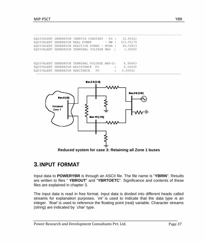
MiP-PSCT YBR
Power Research and Development Consultants Pvt. Ltd. Page 37
------------------------------------------------------------------------------- EQUIVALENT GENERATOR INERTIA CONSTANT - PU : 22.82422 EQUIVALENT GENERATOR REAL POWER - MW : 315.55176 EQUIVALENT GENERATOR REACTIVE POWER - MVAR : 86.34813 EQUIVALENT GENERATOR TERMINAL VOLTAGE MAG : 1.00000
EQUIVALENT GENERATOR TERMINAL VOLTAGE ANG-D: 6.99663 EQUIVALENT GENERATOR RESISTANCE PU : 0.00000 EQUIVALENT GENERATOR REACTANCE PU : 0.00001 -----------------------------------------------------------------------------
Reduced system for case 3: Retaining all Zone 1 buses
3. INPUT FORMAT
Input data to POWERYBR is through an ASCII file. The file name is "YBRIN". Results are written to files " YBROUT" and "YBRTOETC". Significance and contents of these files are explained in chapter 3.
The input data is read in free format. Input data is divided into different heads called streams for explanation purposes. `int' is used to indicate that the data type is an integer. `float' is used to reference the floating point (real) variable. Character streams (string) are indicated by `char' type.
MiP-PSCT YBR
Power Research and Development Consultants Pvt. Ltd. Page 38
In order to reduce the effort in preparing the data, input format for POWERYBR is retained almost same as that required for short circuit study. Hence the document on Short Circuit Study module (Chapter two, Short Circuit Study data preparation for POWERSCS) can be referred for further details. Only those changes in the input data format from the input data format of POWRESCS are explained in this section. The changes are only in stream 2, i.e., System Specification. In stream 2 -
• Line 1 which describes the system size definition remains unaltered. • Program control options given in line 2 and 3 differ in " YBRIN".
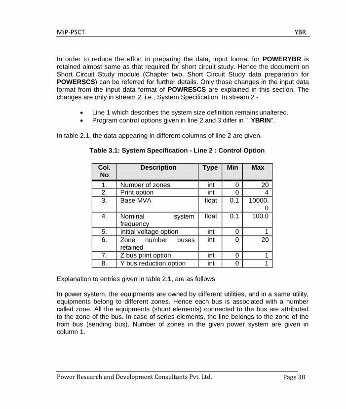
In table 2.1, the data appearing in different columns of line 2 are given.
Table 3.1: System Specification - Line 2 : Control Option
Col. No
Description Type Min Max
1. Number of zones int 0 20 2. Print option int 0 4 3. Base MVA float 0.1 10000.
0 4. Nominal system
frequency float 0.1 100.0
5. Initial voltage option int 0 1 6. Zone number buses
retained int 0 20
7. Z bus print option int 0 1 8. Y bus reduction option int 0 1
Explanation to entries given in table 2.1, are as follows
In power system, the equipments are owned by different utilities, and in a same utility, equipments belong to different zones. Hence each bus is associated with a number called zone. All the equipments (shunt elements) connected to the bus are attributed to the zone of the bus. In case of series elements, the line belongs to the zone of the from bus (sending bus). Number of zones in the given power system are given in column 1.
MiP-PSCT YBR
Power Research and Development Consultants Pvt. Ltd. Page 39
• Print option in table 2.1 is interpreted as - − 0 : No printing of data or results. − 1 : Data printing only. − 2 : Results printing only. − 3 : Both data and results printing. − 4 : Detailed printing of data and results.
• Network parameter (resistance, reactance etc.,) data to POWERYBR is in pu on a
common MVA base. The common MVA base is provided in column 3 of table 2.1.
• Initial voltage option is interpreted as - − 0 : Initial voltage of 1.0 pu is assumed at all the buses. − 1 : Initial voltage is read from the file.
For preparing the data file subsequently used for load flow analysis, dynamic stability study and transient stability study (“LFAIN” file of POWERLFA, "DYSIN" file of POWERDYS and "TRSOUT" file of POWERTRS) initial voltage option should be always 1. Data for initial voltage and operating condition of the system are given in bus data stream. Column 6 entry is interpreted based on the YBUS reduction option as given in column 8.
• If the YBUS reduction option is 1, then this entry gives the number of buses in the
retained system. In the practical power system, buses are grouped to form different zones/areas. If the zone number in column 6 is other than zero, and the YBUS reduction option is 1, then the corresponding zone is retained. This implies, the network elements internal to the system and also the tie line connections are retained. If the zone number is zero (0), then the nodes specified in the subsequent stream are retained.
• Zbus option is interpreted as - − 0 : No print of Zbus for the reduced system. − 1 : Zbus for the reduced system is printed.
• YBUS reduction option given in column 8 is interpreted as -
− 0 : YBUS reduction option for dynamic stability study.

MiP-PSCT YBR
Power Research and Development Consultants Pvt. Ltd. Page 40
− 1 : YBUS reduction option for static and dynamic equivalents.
• Line 3 of stream 2 is interpreted as -
− If the YBUS reduction option is 0, bus numbers to be retained are given (int filed separated by blanks).
− If the YBUS reduction option is 1, and the retained zone number field is
zero (0), then the first entry gives the number of buses retained in the original system (int field). Subsequently, bus numbers to be retained are given (int field separated by blanks).
− If the YBUS reduction option is 1, and the retained zone number field is
other than zero (0), two values (int fields) are read. First value indicates the number of generators in the external system. Second field indicates the generator bus number in the external system to be considered as reference. If there are no generators in the external system, then both the values are entered as zero (0).
• Line 4 in "SCSIN" which gives the fault impedance data is not present in "YBRIN".
• Line 5, which gives the multiplication factors, remains unaltered in "YBRIN".
• Line 6, which gives the travelling shunt fault, is not present in "YBRIN".
If the YBUS reduction option is 1, i.e., equivalent generator is considered, for each retained generator bus, bus number and the corresponding inertia constant in pu on a common base are given as the last stream.
MiP-PSCT YBR
Power Research and Development Consultants Pvt. Ltd.
Page 41
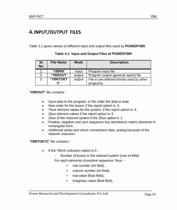
4. INPUT/OUTPUT FILES
Table 3.1 gives names of different input and output files used by POWERYBR.
Table 4.1: Input and Output Files of POWERYBR
Sl. No.
File Name Mode Description
1. "YBRIN" input Program input file 2. "YBROUT" output Program output (general report) file 3. “YBRTOET
C" output File in pre-defined format used by other
programs.
"YBROUT" file contains -
• Input data to the program, in the order the data is read. • New order for the buses, if the report option is 4. • Ybus element values for the system, if the report option is 4. • Zbus element values if the report option is 4. • Zbus of the reduced system if the Zbus option is 1. • Positive, negative and zero sequence bus admittance matrix elements in
rectangular form. • Additional series and shunt connections data, arising because of the
network reduction.
"YBRTOETC" file contains -
• If the YBUS reduction option is 0 - − Number of buses in the reduced system (one int field). For each elements of positive sequence Ybus -
∗ row number (int field), ∗ column number (int field), ∗ real value (float field), ∗ imaginary value (float filed),
MiP-PSCT YBR
Power Research and Development Consultants Pvt. Ltd.
Page 42
in the row wise and column wise. − Negative sequence and Zero sequence Ybus elements in the
above order.
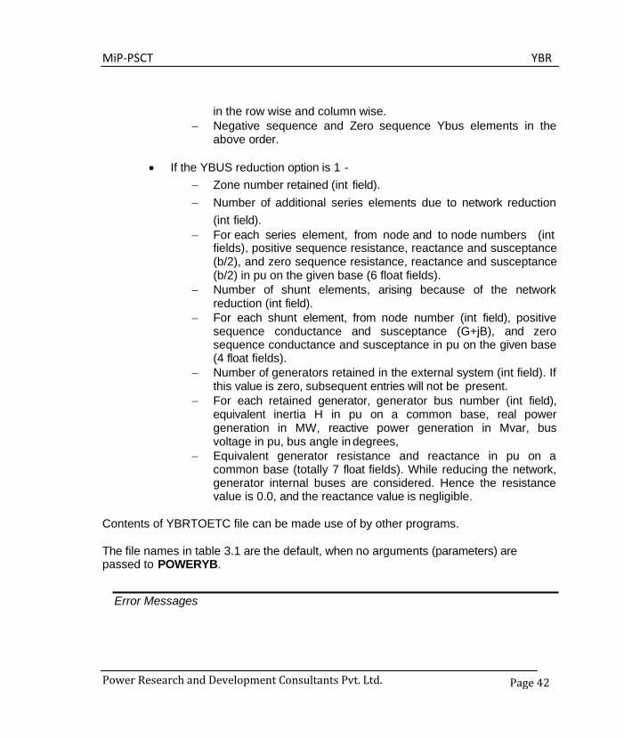
• If the YBUS reduction option is 1 - − Zone number retained (int field). − Number of additional series elements due to network reduction
(int field). − For each series element, from node and to node numbers (int
fields), positive sequence resistance, reactance and susceptance (b/2), and zero sequence resistance, reactance and susceptance (b/2) in pu on the given base (6 float fields).
− Number of shunt elements, arising because of the network reduction (int field).
− For each shunt element, from node number (int field), positive sequence conductance and susceptance (G+jB), and zero sequence conductance and susceptance in pu on the given base (4 float fields).
− Number of generators retained in the external system (int field). If this value is zero, subsequent entries will not be present.
− For each retained generator, generator bus number (int field), equivalent inertia H in pu on a common base, real power generation in MW, reactive power generation in Mvar, bus voltage in pu, bus angle in degrees,
− Equivalent generator resistance and reactance in pu on a common base (totally 7 float fields). While reducing the network, generator internal buses are considered. Hence the resistance value is 0.0, and the reactance value is negligible.
Contents of YBRTOETC file can be made use of by other programs.
The file names in table 3.1 are the default, when no arguments (parameters) are passed to POWERYB.
Error Messages
MiP-PSCT YBR
Power Research and Development Consultants Pvt. Ltd.
Page 43
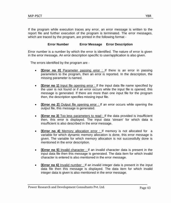
If the program while execution traces any error, an error message is written to the report file and further execution of the program is terminated. The error messages, which are traced by the program, are printed in the following format -
Error Number Error Message Error Description
Error number is a number by which the error is identified. The nature of error is given in the error message. An error description specific to user/application is also given.
The errors identified by the program are -
• [Error no 0] Parameter passing error : If there is an error in passing
parameters to the program, then an error is reported. In the description, the missing parameter is named.
• [Error no 1] Input file opening error : If the input data file name specified by
the user is not found or if an error occurs while the input file is opened, this message is generated. If there are more than one input file for the program then, the description specifies missing input file.
• [Error no 2] Output file opening error : If an error occurs while opening the
output file, this message is generated.
• [Error no 3] Too less parameters to read : If the data provided is insufficient then, this error is displayed. The input data 'stream' for which data is insufficient is also described in the error message.
• [Error no 4] Memory allocation error : If memory is not allocated for a
variable for which dynamic memory allocation is done, this error message is given. The variable for which memory allocation is not successfully done is mentioned in the error description.
• [Error no 5] Invalid character : If an invalid character data is present in the
input data file then this message is generated. The data item for which invalid character is entered is also mentioned in the error message.
• [Error no 6] Invalid number : If an invalid integer data is present in the input
data file then this message is displayed. The data item for which invalid integer data is given is also mentioned in the error message.
MiP-PSCT YBR
Power Research and Development Consultants Pvt. Ltd.
Page 44
• [Error no 7] Invalid value : If the data given exceeds the limits mentioned for each item mentioned under different streams, an error message is given along with a description of the data item.
• [Error no 8] Division by zero : During a mathematical operation, if division by
zero occurs, then this error is generated. The variable, which may have caused this condition, is mentioned in the error description.
• [Error no 9] Diverging error : This message is generated if no convergence
is observed after a specified number of iterations.
• [Error no 10] Error in data, Results not okay : If an erroneous input data is present which doesn't come under any of the above mentioned categories as a result of which wrong results are obtained, then this message is generated.
• These errors are displayed in the output file mentioned by the user. Some of
the common error messages and their probable reason for occurrence are -
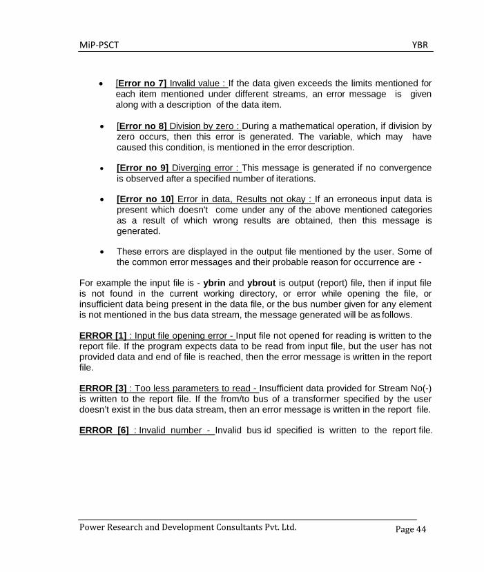
For example the input file is - ybrin and ybrout is output (report) file, then if input file is not found in the current working directory, or error while opening the file, or insufficient data being present in the data file, or the bus number given for any element is not mentioned in the bus data stream, the message generated will be as follows.
ERROR [1] : Input file opening error - Input file not opened for reading is written to the report file. If the program expects data to be read from input file, but the user has not provided data and end of file is reached, then the error message is written in the report file.
ERROR [3] : Too less parameters to read - Insufficient data provided for Stream No(-) is written to the report file. If the from/to bus of a transformer specified by the user doesn’t exist in the bus data stream, then an error message is written in the report file.
ERROR [6] : Invalid number - Invalid bus id specified is written to the report file.

MiP-PSCT YBR
Power Research and Development Consultants Pvt. Ltd Page 45
5. CASE STUDY In this section, a 24-bus system is considered as an example to test POWERYBR single line diagram of a sample 24-node system in figure 5.1. Four different cases are considered to show the capability of POWERYBR. The different cases are as follows: • Case 1 : Reduced system with only generator buses being retained. • Case 2 : Reduced system with retaining generator buses and buses belonging to
Zone 1 only. • Case 3 : Reduced system with retaining buses belongs to Zone 1 only. • Case 4 : Reduced system for dynamic stability.
Figure 22: Sample 24 node System
MiP-PSCT YBR
Power Research and Development Consultants Pvt. Ltd.
Page 46
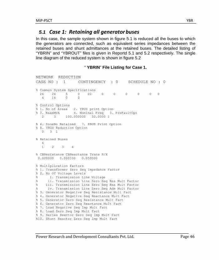
5.1 Case 1: Retaining all generator buses In this case, the sample system shown in figure 5.1 is reduced all the buses to which the generators are connected, such as equivalent series impedances between the retained buses and shunt admittances at the retained buses. The detailed listing of “YBRIN” and “YBROUT” files is given in Reportd 5.1 and 5.2 respectively. The single line diagram of the reduced system is shown in figure 5.2
“ YBRIN” File Listing for Case 1.
NETWORK REDUCTION CASE NO : 1 CONTINGENCY : 0 SCHEDULE NO : 0
% Common System Specifications 24 24 5 0 22 0 0 0 0 0 0 4 14 0 0
% Control Options % 1. No of Areas 2. YBUS print Option % 3. BaseMVA 4. Nominal Freq 5. PreFaultOpt
2 3 100.000000 50.0000 1
% 6. ZoneNo Retained 7. ZBUS Print Option % 8. YBUS Reduction Option
0 3 1
% Retained Buses 4 1 2 3 4
% CBResistance CBReactance Trans R/X 0.000000 0.000100 0.050000
% Multiplication Factors % 1. Transformer Zero Seq Impedance Factor % 2. No Of Voltage Levels % i. Transmission Line Voltage % ii. Transmission Line Zero Seq Res Mult Factor % iii. Transmission Line Zero Seq Rea Mult Factor % iv. Transmission Line Zero Seq Adm Mult Factor % 3. Generator Negative Seq Resistance Mult Fact % 4. Generator Negative Seq Reactance Mult Fact % 5. Generator Zero Seq Resistance Mult Fact % 6. Generator Zero Seq Reactance Mult Fact % 7. Load Negative Seq Imp Mult Fact % 8. Load Zero Seq Imp Mult Fact % 9. Series Reactor Zero Seq Imp Mult Fact %10. Shunt Reactor Zero Seq Imp Mult Fact

MiP-PSCT YBR
Power Research and Development Consultants Pvt. Ltd.
Page 47
0.90000 3 11.0000 2.5000 2.5000 0.0250 220.0000 2.5000 2.5000 0.0250 400.0000 2.5000 2.5000 0.0250 0.1750 0.1750 0.0375 0.0375 0.8100 1.6000 1.0000
% Bus Data 0.6250
% BusId AreaNo BaseVolt BusName VMag VAng % PGen(mw) QGen(mvar) PLoad(mw) QLoad(mvar) QComp(mvar)
BUS1 1.02000 0.00000 19.58 0.00 0.00 0.00
BUS2 1.02000 1.60957 22.50 0.00 0.00 0.00
BUS3 1.02000 3.52133 39.57 0.00 0.00 0.00
BUS4 1.02000 3.90614 35.27 0.00 0.00 0.00
BUS5 1.01639 -4.31840 0.00 0.00 0.00 0.00
BUS6 1.00496 -10.40950 0.00 70.24 30.10 30.00
BUS7 0.96764 -19.84798 0.00 146.63 39.10 30.00
BUS8 0.97560 -14.53740 0.00 0.00 0.00 0.00
9 1 1 220.000 BUS9 0.97373 -14.85133
0.00 0.00 29.45 9.82 0.00 BUS10 0.96503 -15.33271
0.00 87.82 48.79 0.00 BUS11 0.97330 -15.09323
0.00 34.35 14.72 0.00 BUS12 0.95674 -17.67398
0.00 29.10 9.70 0.00 BUS13 0.96415 -16.51734
0.00 146.27 58.51 0.00 BUS14 0.98142 -12.32362
0.00 0.00 0.00 0.00 BUS15 1.01044 -2.00128
0.00 0.00 0.00 0.00 BUS16 0.96382 -16.85907
0.00 224.24 58.50 0.00 BUS17 0.95927 -17.27090
0.00 58.31 24.30 0.00 BUS18 1.00393 -3.22595
0.00 0.00 0.00 0.00 BUS19 0.99224 -5.08417
0.00 129.29 99.46 0.00 BUS20 0.99105 -5.82668
0.00 49.69 34.78 0.00
1 1 1 11.000 563.70 2 1 2 11.000
125.00 3 1 2 11.000
190.00 4 1 1 11.000
380.00 5 1 1 220.000
0.00 6 1 1 220.000
0.00 7 1 1 220.000
0.00 8 1 1 220.000
0.00
10 1 1 220.000 0.00 11 1 1 220.000
0.00 12 1 1 220.000
0.00 13 1 1 220.000
0.00 14 1 1 400.000
0.00 15 1 1 400.000
0.00 16 1 1 220.000
0.00 17 1 1 220.000
0.00 18 1 2 220.000
0.00 19 1 2 220.000
0.00 20 1 2 220.000
0.00
MiP-PSCT YBR
Power Research and Development Consultants Pvt. Ltd.
Page 48
21 1 2 220.000 BUS21 0.98818 -3.02889
0.00 0.00 72.40 47.60 0.00 22 1 2 220.000 BUS22 0.99839 -2.42293
0.00 0.00 0.00 0.00 0.00 23 1 2 220.000 BUS23 0.94695 -7.39961
0.00 0.00 48.17 28.90 0.00 24 1 2 220.000 BUS24 0.97263 -7.97324
0.00 0.00 93.19 49.05 0.00
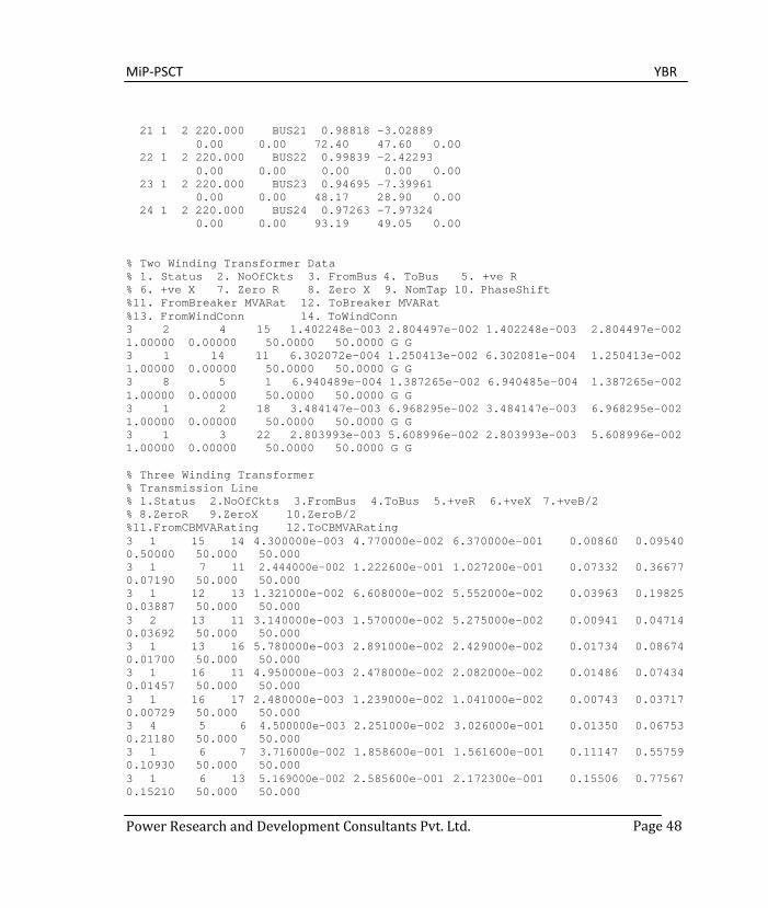
% Two Winding Transformer Data % 1. Status 2. NoOfCkts 3. FromBus 4. ToBus 5. +ve R % 6. +ve X 7. Zero R 8. Zero X 9. NomTap 10. PhaseShift %11. FromBreaker MVARat 12. ToBreaker MVARat %13. FromWindConn 14. ToWindConn 3 2 4 15 1.402248e-003 2.804497e-002 1.402248e-003 2.804497e-002 1.00000 0.00000 50.0000 50.0000 G G 3 1 14 11 6.302072e-004 1.250413e-002 6.302081e-004 1.250413e-002 1.00000 0.00000 50.0000 50.0000 G G 3 8 5 1 6.940489e-004 1.387265e-002 6.940485e-004 1.387265e-002 1.00000 0.00000 50.0000 50.0000 G G 3 1 2 18 3.484147e-003 6.968295e-002 3.484147e-003 6.968295e-002 1.00000 0.00000 50.0000 50.0000 G G 3 1 3 22 2.803993e-003 5.608996e-002 2.803993e-003 5.608996e-002 1.00000 0.00000 50.0000 50.0000 G G
% Three Winding Transformer % Transmission Line % 1.Status 2.NoOfCkts 3.FromBus 4.ToBus 5.+veR 6.+veX 7.+veB/2 % 8.ZeroR 9.ZeroX 10.ZeroB/2 %11.FromCBMVARating 12.ToCBMVARating 3 1 15 14 4.300000e-003 4.770000e-002 6.370000e-001 0.00860 0.09540 0.50000 50.000 50.000 3 1 7 11 2.444000e-002 1.222600e-001 1.027200e-001 0.07332 0.36677 0.07190 50.000 50.000 3 1 12 13 1.321000e-002 6.608000e-002 5.552000e-002 0.03963 0.19825 0.03887 50.000 50.000 3 2 13 11 3.140000e-003 1.570000e-002 5.275000e-002 0.00941 0.04714 0.03692 50.000 50.000 3 1 13 16 5.780000e-003 2.891000e-002 2.429000e-002 0.01734 0.08674 0.01700 50.000 50.000 3 1 16 11 4.950000e-003 2.478000e-002 2.082000e-002 0.01486 0.07434 0.01457 50.000 50.000 3 1 16 17 2.480000e-003 1.239000e-002 1.041000e-002 0.00743 0.03717 0.00729 50.000 50.000 3 4 5 6 4.500000e-003 2.251000e-002 3.026000e-001 0.01350 0.06753 0.21180 50.000 50.000 3 1 6 7 3.716000e-002 1.858600e-001 1.561600e-001 0.11147 0.55759 0.10930 50.000 50.000 3 1 6 13 5.169000e-002 2.585600e-001 2.172300e-001 0.15506 0.77567 0.15210 50.000 50.000
MiP-PSCT YBR
Power Research and Development Consultants Pvt. Ltd.
Page 49
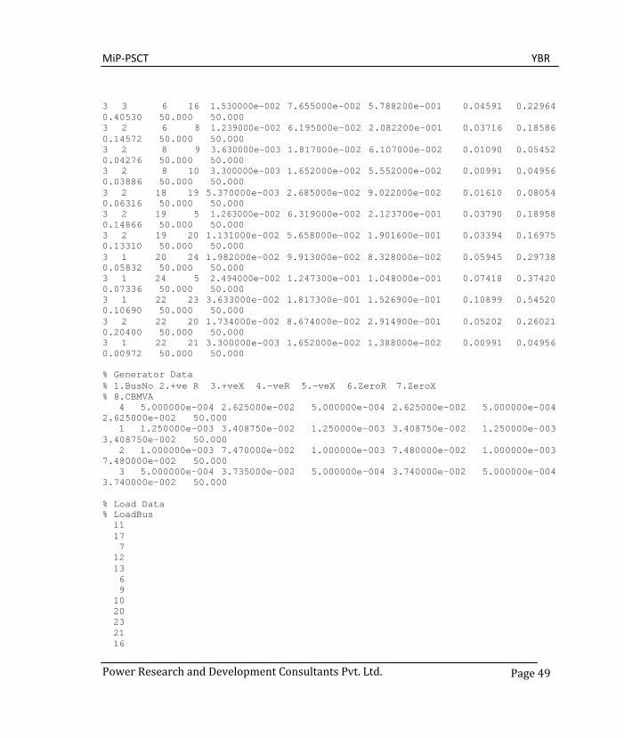
3 3 6 16 1.530000e-002 7.655000e-002 5.788200e-001 0.04591 0.22964 0.40530 50.000 50.000 3 2 6 8 1.239000e-002 6.195000e-002 2.082200e-001 0.03716 0.18586 0.14572 50.000 50.000 3 2 8 9 3.630000e-003 1.817000e-002 6.107000e-002 0.01090 0.05452 0.04276 50.000 50.000 3 2 8 10 3.300000e-003 1.652000e-002 5.552000e-002 0.00991 0.04956 0.03886 50.000 50.000 3 2 18 19 5.370000e-003 2.685000e-002 9.022000e-002 0.01610 0.08054 0.06316 50.000 50.000 3 2 19 5 1.263000e-002 6.319000e-002 2.123700e-001 0.03790 0.18958 0.14866 50.000 50.000 3 2 19 20 1.131000e-002 5.658000e-002 1.901600e-001 0.03394 0.16975 0.13310 50.000 50.000 3 1 20 24 1.982000e-002 9.913000e-002 8.328000e-002 0.05945 0.29738 0.05832 50.000 50.000 3 1 24 5 2.494000e-002 1.247300e-001 1.048000e-001 0.07418 0.37420 0.07336 50.000 50.000 3 1 22 23 3.633000e-002 1.817300e-001 1.526900e-001 0.10899 0.54520 0.10690 50.000 50.000 3 2 22 20 1.734000e-002 8.674000e-002 2.914900e-001 0.05202 0.26021 0.20400 50.000 50.000 3 1 22 21 3.300000e-003 1.652000e-002 1.388000e-002 0.00991 0.04956 0.00972 50.000 50.000 % Generator Data % 1.BusNo 2.+ve R 3.+veX 4.-veR 5.-veX 6.ZeroR 7.ZeroX % 8.CBMVA
4 5.000000e-004 2.625000e-002 5.000000e-004 2.625000e-002 5.000000e-004 2.625000e-002 50.000
1 1.250000e-003 3.408750e-002 1.250000e-003 3.408750e-002 1.250000e-003 3.408750e-002 50.000
2 1.000000e-003 7.470000e-002 1.000000e-003 7.480000e-002 1.000000e-003 7.480000e-002 50.000
3 5.000000e-004 3.735000e-002 5.000000e-004 3.740000e-002 5.000000e-004 3.740000e-002 50.000
% Load Data % LoadBus 11 17 7 12 13 6 9 10 20 23 21 16
MiP-PSCT YBR
Power Research and Development Consultants Pvt. Ltd.
Page 51
19 24
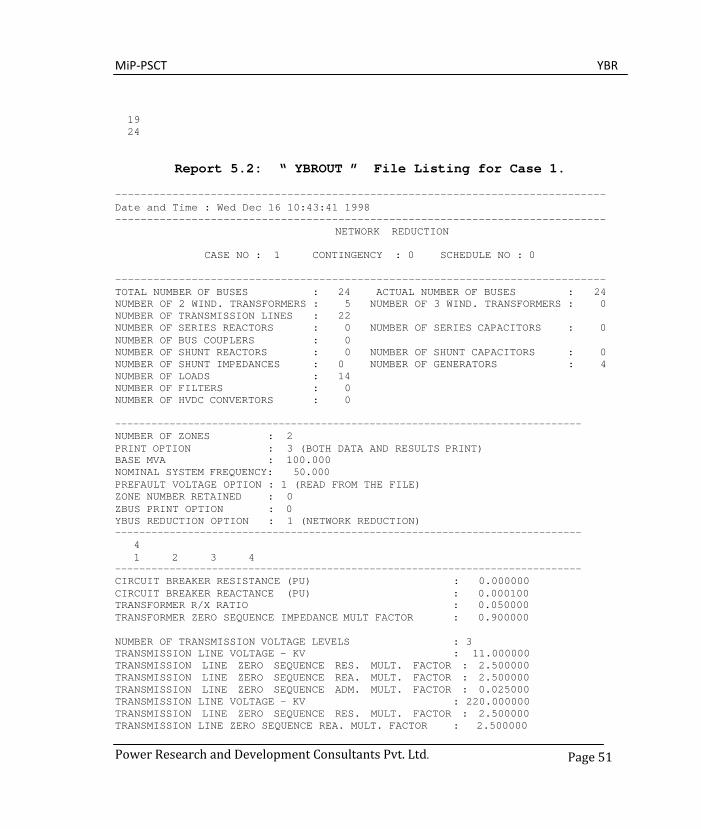
Report 5.2: “ YBROUT ” File Listing for Case 1.
----------------------------------------------------------------------------- Date and Time : Wed Dec 16 10:43:41 1998 -----------------------------------------------------------------------------
NETWORK REDUCTION
CASE NO : 1 CONTINGENCY : 0 SCHEDULE NO : 0
----------------------------------------------------------------------------- TOTAL NUMBER OF BUSES : 24 ACTUAL NUMBER OF BUSES : 24 NUMBER OF 2 WIND. TRANSFORMERS : 5 NUMBER OF 3 WIND. TRANSFORMERS : 0 NUMBER OF TRANSMISSION LINES : 22 NUMBER OF SERIES REACTORS : 0 NUMBER OF SERIES CAPACITORS : 0 NUMBER OF BUS COUPLERS : 0 NUMBER OF SHUNT REACTORS : 0 NUMBER OF SHUNT CAPACITORS : 0 NUMBER OF SHUNT IMPEDANCES : 0 NUMBER OF GENERATORS : 4 NUMBER OF LOADS : 14 NUMBER OF FILTERS : 0 NUMBER OF HVDC CONVERTORS : 0 ----------------------------------------------------------------------------- NUMBER OF ZONES : 2 PRINT OPTION : 3 (BOTH DATA AND RESULTS PRINT) BASE MVA : 100.000 NOMINAL SYSTEM FREQUENCY: 50.000 PREFAULT VOLTAGE OPTION : 1 (READ FROM THE FILE) ZONE NUMBER RETAINED : 0 ZBUS PRINT OPTION : 0 YBUS REDUCTION OPTION : 1 (NETWORK REDUCTION) -----------------------------------------------------------------------------
4 1 2 3 4
----------------------------------------------------------------------------- CIRCUIT BREAKER RESISTANCE (PU) : 0.000000 CIRCUIT BREAKER REACTANCE (PU) : 0.000100 TRANSFORMER R/X RATIO : 0.050000 TRANSFORMER ZERO SEQUENCE IMPEDANCE MULT FACTOR : 0.900000
NUMBER OF TRANSMISSION VOLTAGE LEVELS : 3 TRANSMISSION LINE VOLTAGE - KV : 11.000000 TRANSMISSION LINE ZERO SEQUENCE RES. MULT. FACTOR : 2.500000 TRANSMISSION LINE ZERO SEQUENCE REA. MULT. FACTOR : 2.500000 TRANSMISSION LINE ZERO SEQUENCE ADM. MULT. FACTOR : 0.025000 TRANSMISSION LINE VOLTAGE - KV : 220.000000 TRANSMISSION LINE ZERO SEQUENCE RES. MULT. FACTOR : 2.500000 TRANSMISSION LINE ZERO SEQUENCE REA. MULT. FACTOR : 2.500000
MiP-PSCT YBR
Power Research and Development Consultants Pvt. Ltd.
Page 52
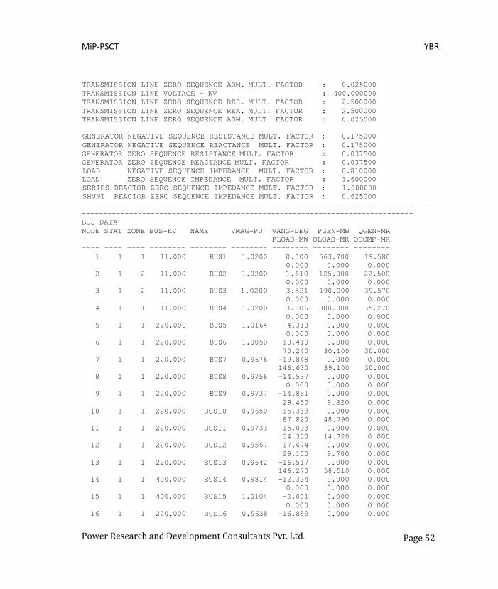
TRANSMISSION LINE ZERO SEQUENCE ADM. MULT. FACTOR : 0.025000 TRANSMISSION LINE VOLTAGE - KV : 400.000000 TRANSMISSION LINE ZERO SEQUENCE RES. MULT. FACTOR : 2.500000 TRANSMISSION LINE ZERO SEQUENCE REA. MULT. FACTOR : 2.500000 TRANSMISSION LINE ZERO SEQUENCE ADM. MULT. FACTOR : 0.025000
GENERATOR NEGATIVE SEQUENCE RESISTANCE MULT. FACTOR : 0.175000 GENERATOR NEGATIVE SEQUENCE REACTANCE MULT. FACTOR : 0.175000 GENERATOR ZERO SEQUENCE RESISTANCE MULT. FACTOR : 0.037500 GENERATOR ZERO SEQUENCE REACTANCE MULT. FACTOR : 0.037500 LOAD NEGATIVE SEQUENCE IMPEDANCE MULT. FACTOR : 0.810000 LOAD ZERO SEQUENCE IMPEDANCE MULT. FACTOR : 1.600000 SERIES REACTOR ZERO SEQUENCE IMPEDANCE MULT. FACTOR : 1.000000 SHUNT REACTOR ZERO SEQUENCE IMPEDANCE MULT. FACTOR : 0.625000 ----------------------------------------------------------------------------- ----------------------------------------------------------------------------- BUS DATA NODE ----
STAT ----
ZONE ----
BUS-KV --------
NAME --------
VMAG-PU --------
VANG-DEG PLOAD-MW --------
PGEN-MW QLOAD-MR --------
QGEN-MR QCOMP-MR --------
1 1 1 11.000 BUS1 1.0200 0.000 563.700 19.580
0.000 0.000 0.000 2 1 2 11.000 BUS2 1.0200 1.610 125.000 22.500
0.000 0.000 0.000 3 1 2 11.000 BUS3 1.0200 3.521 190.000 39.570
0.000 0.000 0.000 4 1 1 11.000 BUS4 1.0200 3.906 380.000 35.270
0.000 0.000 0.000 5 1 1 220.000 BUS5 1.0164 -4.318 0.000 0.000
0.000 0.000 0.000 6 1 1 220.000 BUS6 1.0050 -10.410 0.000 0.000
70.240 30.100 30.000 7 1 1 220.000 BUS7 0.9676 -19.848 0.000 0.000
146.630 39.100 30.000 8 1 1 220.000 BUS8 0.9756 -14.537 0.000 0.000
0.000 0.000 0.000 9 1 1 220.000 BUS9 0.9737 -14.851 0.000 0.000
29.450 9.820 0.000 10 1 1 220.000 BUS10 0.9650 -15.333 0.000 0.000
87.820 48.790 0.000 11 1 1 220.000 BUS11 0.9733 -15.093 0.000 0.000
34.350 14.720 0.000 12 1 1 220.000 BUS12 0.9567 -17.674 0.000 0.000
29.100 9.700 0.000 13 1 1 220.000 BUS13 0.9642 -16.517 0.000 0.000
146.270 58.510 0.000 14 1 1 400.000 BUS14 0.9814 -12.324 0.000 0.000
0.000 0.000 0.000 15 1 1 400.000 BUS15 1.0104 -2.001 0.000 0.000
0.000 0.000 0.000 16 1 1 220.000 BUS16 0.9638 -16.859 0.000 0.000

MiP-PSCT YBR
Power Research and Development Consultants Pvt. Ltd.
Page 53
224.240 58.500 0.000 17 1 1 220.000 BUS17 0.9593 -17.271 0.000 0.000
58.310 24.300 0.000 18 1 2 220.000 BUS18 1.0039 -3.226 0.000 0.000
0.000 0.000 0.000 19 1 2 220.000 BUS19 0.9922 -5.084 0.000 0.000
129.290 99.460 0.000 20 1 2 220.000 BUS20 0.9911 -5.827 0.000 0.000
49.690 34.780 0.000 21 1 2 220.000 BUS21 0.9882 -3.029 0.000 0.000
72.400 47.600 0.000 22 1 2 220.000 BUS22 0.9984 -2.423 0.000 0.000
0.000 0.000 0.000 23 1 2 220.000 BUS23 0.9470 -7.400 0.000 0.000
48.170 28.900 0.000 24 1 2 220.000 BUS24 0.9726 -7.973 0.000 0.000
93.190 49.050 0.000 ----------------------------------------------------------------------------- TRANSFORMER DATA
STAT CKTS FROM FROM TO TO POSITIVE ZERO NODE NAME
---- ---- ---- --------
NODE NAME ---- --------
R(P.U) X(P.U.) TAP PHASE
-------- --------
R(P.U.) X(P.U.) FB-MVA TB-MVA ------- ------- -- --
3 2 4 BUS4 15 BUS15 0.00140 0.02804 0.00140 0.02804
1.00000 0.000 50 50 G G 3 1 14 BUS14 11 BUS11 0.00063 0.01250 0.00063 0.01250
1.00000 0.000 50 50 G G 3 8 5 BUS5 1 BUS1 0.00069 0.01387 0.00069 0.01387
1.00000 0.000 50 50 G G 3 1 2 BUS2 18 BUS18 0.00348 0.06968 0.00348 0.06968
1.00000 0.000 50 50 G G 3 1 3 BUS3 22 BUS22 0.00280 0.05609 0.00280 0.05609
TRANSMISSION LINE DATA
1.00000 0.000 50 50 G G
STAT CKTS FROM FROM TO TO NODE NAME NODE NAME RP(P.U) XP(P.U) BP/2(PU)
RZ(P.U) XZ(P.U) BZ/2(PU) FC-MVA TC-MVA ---- ---- ---- -------- ---- -------- -------- -------- -------- ------ -----
3 1 15 BUS15 14 BUS14 0.00430 0.04770 0.63700 0.00860 0.09540 0.50000 50 50 3 1 7 BUS7 11 BUS11 0.02444 0.12226 0.10272 0.07332 0.36677 0.07190 50 50 3 1 12 BUS12 13 BUS13 0.01321 0.06608 0.05552 0.03963 0.19825 0.03887 50 50 3 2 13 BUS13 11 BUS11 0.00314 0.01570 0.05275 0.00941 0.04714 0.03692 50 50 3 1 13 BUS13 16 BUS16 0.00578 0.02891 0.02429 0.01734 0.08674 0.01700 50 50 3 1 16 BUS16 11 BUS11 0.00495 0.02478 0.02082

MiP-PSCT YBR
Power Research and Development Consultants Pvt. Ltd.
Page 54
0.01486 0.07434 0.01457 50 50 3 1 16 BUS16 17 BUS17 0.00248 0.01239 0.01041 0.00743 0.03717 0.00729 50 50 3 4 5 BUS5 6 BUS6 0.00450 0.02251 0.30260 0.01350 0.06753 0.21180 50 50 3 1 6 BUS6 7 BUS7 0.03716 0.18586 0.15616 0.11147 0.55759 0.10930 50 50 3 1 6 BUS6 13 BUS13 0.05169 0.25856 0.21723 0.15506 0.77567 0.15210 50 50 3 3 6 BUS6 16 BUS16 0.01530 0.07655 0.57882 0.04591 0.22964 0.40530 50 50 3 2 6 BUS6 8 BUS8 0.01239 0.06195 0.20822 0.03716 0.18586 0.14572 50 50 3 2 8 BUS8 9 BUS9 0.00363 0.01817 0.06107 0.01090 0.05452 0.04276 50 50 3 2 8 BUS8 10 BUS10 0.00330 0.01652 0.05552 0.00991 0.04956 0.03886 50 50 3 2 18 BUS18 19 BUS19 0.00537 0.02685 0.09022 0.01610 0.08054 0.06316 50 50 3 2 19 BUS19 5 BUS5 0.01263 0.06319 0.21237 0.03790 0.18958 0.14866 50 50 3 2 19 BUS19 20 BUS20 0.01131 0.05658 0.19016 0.03394 0.16975 0.13310 50 50 3 1 20 BUS20 24 BUS24 0.01982 0.09913 0.08328 0.05945 0.29738 0.05832 50 50 3 1 24 BUS24 5 BUS5 0.02494 0.12473 0.10480 0.07418 0.37420 0.07336 50 50 3 1 22 BUS22 23 BUS23 0.03633 0.18173 0.15269 0.10899 0.54520 0.10690 50 50 3 2 22 BUS22 20 BUS20 0.01734 0.08674 0.29149 0.05202 0.26021 0.20400 50 50 3 1 22 BUS22 21 BUS21 0.00330 0.01652 0.01388 0.00991 0.04956 0.00972 50 50
-----------------------------------------------------------------------------

MiP-PSCT YBR
Power Research and Development Consultants Pvt. Ltd.
Page 55
GENERATOR DATA
FROM FROM POSITIVE NEGATIVE ZERO NODE NAME R(P.U) X(P.U.) R(P.U.) X(P.U.) R(P.U.) X(P.U.) CB-MVA ---- -------- -------- -------- -------- -------- -------- -------- ------
4 BUS4 0.00050 0.02625 0.00050 0.02625 0.00050 0.02625 50
1 BUS1 0.00125 0.03409 0.00125 0.03409 0.00125 0.03409 50 2 BUS2 0.00100 0.07470 0.00100 0.07480 0.00100 0.07480 50 3 BUS3 0.00050 0.03735 0.00050 0.03740 0.00050 0.03740 50
-----------------------------------------------------------------------------
LOAD DATA
NODE NAME ---- -------- 11 BUS11 17 BUS17 7 BUS7
12 BUS12 13 BUS13 6 BUS6 9 BUS9
10 BUS10 20 BUS20 23 BUS23 21 BUS21 16 BUS16 19 BUS19 24 BUS24
Number of reduced buses : 4 Reduced bus array :
1 2 3 4 ----------------------------------------------------------------------------- POSITIVE SEQUENCE ADMITTANCE MATRIX ELEMENTS FOR THE GIVEN SYSTEM ----------------------------------------------------------------------------- ROW NO COLUMN NO REAL IMAGINARY ------ --------- ---------- ----------
1 1 4.84122 -12.15417 1 2 -0.00502 4.64545 1 3 0.05451 2.69446 1 4 1.13690 4.56290 2 1 -0.00502 4.64545 2 2 1.01332 -6.70635 2 3 0.04604 1.48618 2 4 0.08059 0.35653 3 1 0.05451 2.69446 3 2 0.04604 1.48618 3 3 1.46098 -4.75623 3 4 0.05115 0.20579
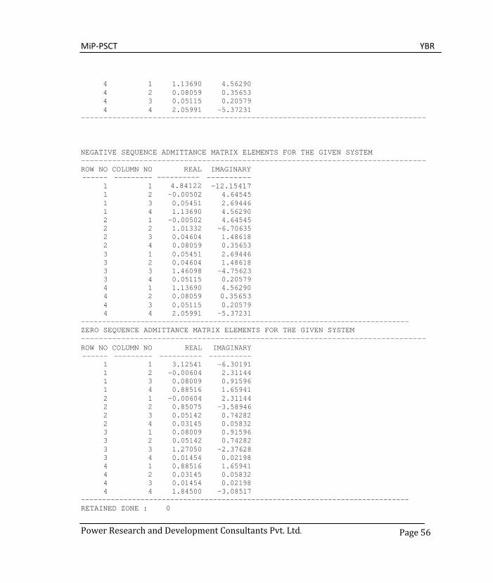
MiP-PSCT YBR
Power Research and Development Consultants Pvt. Ltd.
Page 56
4 1 1.13690 4.56290 4 2 0.08059 0.35653 4 3 0.05115 0.20579 4 4 2.05991 -5.37231
-----------------------------------------------------------------------------
NEGATIVE SEQUENCE ADMITTANCE MATRIX ELEMENTS FOR THE GIVEN SYSTEM ----------------------------------------------------------------------------- ROW NO ------
1
COLUMN NO ---------
1
REAL ----------
4.84122
IMAGINARY ---------- -12.15417
1 2 -0.00502 4.64545 1 3 0.05451 2.69446 1 4 1.13690 4.56290 2 1 -0.00502 4.64545 2 2 1.01332 -6.70635 2 3 0.04604 1.48618 2 4 0.08059 0.35653 3 1 0.05451 2.69446 3 2 0.04604 1.48618 3 3 1.46098 -4.75623 3 4 0.05115 0.20579 4 1 1.13690 4.56290 4 2 0.08059 0.35653 4 3 0.05115 0.20579 4 4 2.05991 -5.37231
----------------------------------------------------------------------------- ZERO SEQUENCE ADMITTANCE MATRIX ELEMENTS FOR THE GIVEN SYSTEM ----------------------------------------------------------------------------- ROW NO COLUMN NO REAL IMAGINARY ------ --------- ---------- ----------
1 1 3.12541 -6.30191 1 2 -0.00604 2.31144 1 3 0.08009 0.91596 1 4 0.88516 1.65941 2 1 -0.00604 2.31144 2 2 0.85075 -3.58946 2 3 0.05142 0.74282 2 4 0.03145 0.05832 3 1 0.08009 0.91596 3 2 0.05142 0.74282 3 3 1.27050 -2.37628 3 4 0.01454 0.02198 4 1 0.88516 1.65941 4 2 0.03145 0.05832 4 3 0.01454 0.02198 4 4 1.84500 -3.08517
----------------------------------------------------------------------------- RETAINED ZONE : 0

MiP-PSCT YBR
Power Research and Development Consultants Pvt. Ltd.
Page 57
NUMBER OF SERIES ELEMENTS IN THE REDUCED ZONES : 6 SERIES CONNECTIONS SLNO FROM NAME TO NAME RP XP BP/2 RZ XZ BZ/2 ---- ---- -------- ---- -------- -------- -------- ---- -------- -------- --- 1 1 BUS1 2 BUS2 0.000233 0.215264 0.0 0.001131 0.432628 0.0 2 1 BUS1 3 BUS3 -0.007506 0.370980 0.0 -0.094733 1.083469 0.0 3 1 BUS1 4 BUS4 -0.051414 0.206348 0.0 -0.250246 0.469137 0.0 4 2 BUS2 3 BUS3 -0.020825 0.672222 0.0 -0.092744 1.339802 0.0 5 2 BUS2 4 BUS4 -0.603154 2.668483 0.0 -7.163429 13.282542 0.0 6 3 BUS3 4 BUS4 -1.137457 4.576533 0.0 -20.93122 31.641287 0.0
----------------------------------------------------------------------------- NUMBER OF SHUNT ELEMENTS IN THE REDUCED ZONES : 4 SHUNT CONNECTIONS IN (G+JB) FORMAT - PU SLNO FROM NAME GP BP GZ BZ ---- ---- -------- -------- -------- -------- --------
1 1 BUS1 6.02761 -0.25136 4.08461 -1.41509 2 2 BUS2 1.13492 -0.21819 0.92758 -0.47688 3 3 BUS3 1.61269 -0.36980 1.41655 -0.69552 4 4 BUS4 3.32855 -0.24709 2.77616 -1.34544
------------------------------------------------------------------------------- Date and Time : Wed Dec 16 10:43:41 1998 -----------------------------------------------------------------------------
Figure 23: Reduced System for case 1
1
3 4
2

MiP-PSCT YBR
Power Research and Development Consultants Pvt. Ltd.
Page 58
5.2 Case 2: Retaining all generator buses and zone 1 buses
In this case, the sample system shown in Report 5.1 is reduced with retaining all the buses to which the generators are connected, such as buses 1,2, 3 and 4. The buses which are belonging to zone 1, such as buses 5, 6, 7, 8, 9,10, 11,12,13,14,15,16 and 17 are also retained. All connections in zone 2 are reduced as equivalent series impedances and shunt admittances. Only a portion of file specification is shown in Report 5.3 and 5.4 for “YBRIN” and “YBROUT” respectively. The single line diagram of the reduced network is shown in Report 5.3
Report 5.3: “ YBRIN “ File Listing for Case 2.
NETWORK REDUCTION CASE NO : 2 CONTINGENCY : 0 SCHEDULE NO : 0
% Common System Specifications 24 24 5 0 22 0 0 0 0 0 0 4 14 0 0
% Control Options % 1. No of Areas 2. YBUS print Option % 3. BaseMVA 4. Nominal Freq 5. PreFaultOpt
2 3 100.000000 50.0000 1
% 6. ZoneNo Retained 7. ZBUS Print Option % 8. YBUS Reduction Option
0 3 1
% Retained Buses 17
1 2 3 4 5 6 7 8 9 10 11 12 13 14 15 16 17
% CBResistance CBReactance Trans R/X 0.000000 0.000100 0.050000
% Multiplication Factors % 1. Transformer Zero Seq Impedance Factor % 2. No Of Voltage Levels % i. Transmission Line Voltage % ii. Transmission Line Zero Seq Res Mult Factor % iii. Transmission Line Zero Seq Rea Mult Factor % iv. Transmission Line Zero Seq Adm Mult Factor % 3. Generator Negative Seq Resistance Mult Fact % 4. Generator Negative Seq Reactance Mult Fact % 5. Generator Zero Seq Resistance Mult Fact

MiP-PSCT YBR
Power Research and Development Consultants Pvt. Ltd.
Page 59
% 6. Generator Zero Seq Reactance Mult Fact % 7. Load Negative Seq Imp Mult Fact % 8. Load Zero Seq Imp Mult Fact % 9. Series Reactor Zero Seq Imp Mult Fact %10. Shunt Reactor Zero Seq Imp Mult Fact 0.90000 3 11.0000 2.5000 2.5000 0.0250
220.0000 2.5000 2.5000 0.0250 400.0000 2.5000 2.5000 0.0250
0.1750 0.1750 0.0375 0.0375 0.8100 1.6000 1.0000 0.6250
% Bus Data not given
Report 5.4: “YBROUT “ File Listing for Case 2 ----------------------------------------------------------------------------- Date and Time: Wed Dec 16 10:50:19 1998 -----------------------------------------------------------------------------
NETWORK REDUCTION CASE NO : 2 CONTINGENCY : 0 SCHEDULE NO : 0
----------------------------------------------------------------------------- TOTAL NUMBER OF BUSES : 24 ACTUAL NUMBER OF BUSES : 24 NUMBER OF 2 WIND. TRANSFORMERS : 5 NUMBER OF 3 WIND. TRANSFORMERS : 0 NUMBER OF TRANSMISSION LINES : 22 NUMBER OF SERIES REACTORS : 0 NUMBER OF SERIES CAPACITORS : 0 NUMBER OF BUS COUPLERS : 0 NUMBER OF SHUNT REACTORS : 0 NUMBER OF SHUNT CAPACITORS : 0 NUMBER OF SHUNT IMPEDANCES : 0 NUMBER OF GENERATORS : 4 NUMBER OF LOADS : 14 NUMBER OF FILTERS : 0 NUMBER OF HVDC CONVERTORS : 0
----------------------------------------------------------------------------- NUMBER OF ZONES : 2 PRINT OPTION : 3 (BOTH DATA AND RESULTS PRINT) BASE MVA : 100.000 NOMINAL SYSTEM FREQUENCY: 50.000 PREFAULT VOLTAGE OPTION : 1 (READ FROM THE FILE) ZONE NUMBER RETAINED : 0 ZBUS PRINT OPTION : 3 YBUS REDUCTION OPTION : 1 (NETWORK REDUCTION) ----------------------------------------------------------------------------- 17 1 2 3 4 5 6 7 8 9 10
11 12 13 14 15 16 17 ----------------------------------------------------------------------------- CIRCUIT BREAKER RESISTANCE (PU) : 0.000000 CIRCUIT BREAKER REACTANCE (PU) : 0.000100 TRANSFORMER R/X RATIO : 0.050000 TRANSFORMER ZERO SEQUENCE IMPEDANCE MULT FACTOR : 0.900000
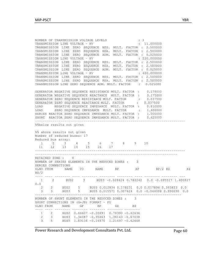
MiP-PSCT YBR
Power Research and Development Consultants Pvt. Ltd.
Page 60
NUMBER OF TRANSMISSION VOLTAGE LEVELS : 3 TRANSMISSION LINE VOLTAGE - KV : 11.000000 TRANSMISSION LINE ZERO SEQUENCE RES. MULT. FACTOR : 2.500000 TRANSMISSION LINE ZERO SEQUENCE REA. MULT. FACTOR : 2.500000 TRANSMISSION LINE ZERO SEQUENCE ADM. MULT. FACTOR : 0.025000 TRANSMISSION LINE VOLTAGE - KV : 220.000000 TRANSMISSION LINE ZERO SEQUENCE RES. MULT. FACTOR : 2.500000 TRANSMISSION LINE ZERO SEQUENCE REA. MULT. FACTOR : 2.500000 TRANSMISSION LINE ZERO SEQUENCE ADM. MULT. FACTOR : 0.025000 TRANSMISSION LINE VOLTAGE - KV : 400.000000 TRANSMISSION LINE ZERO SEQUENCE RES. MULT. FACTOR : 2.500000 TRANSMISSION LINE ZERO SEQUENCE REA. MULT. FACTOR : 2.500000 TRANSMISSION LINE ZERO SEQUENCE ADM. MULT. FACTOR : 0.025000
GENERATOR NEGATIVE SEQUENCE RESISTANCE MULT. FACTOR : 0.175000 GENERATOR NEGATIVE SEQUENCE REACTANCE MULT. FACTOR : 0.175000 GENERATOR ZERO SEQUENCE RESISTANCE MULT. FACTOR : 0.037500 GENERATOR ZERO SEQUENCE REACTANCE MULT. FACTOR : 0.037500 LOAD NEGATIVE SEQUENCE IMPEDANCE MULT. FACTOR : 0.810000 LOAD ZERO SEQUENCE IMPEDANCE MULT. FACTOR : 1.600000 SERIES REACTOR ZERO SEQUENCE IMPEDANCE MULT. FACTOR : 1.000000 SHUNT REACTOR ZERO SEQUENCE IMPEDANCE MULT. FACTOR : 0.625000 ----------------------------------------------------------------------------- %%below results not given
%% above results not given Number of reduced buses: 17 Reduced bus array:
1 2 3 4 5 6 7 8 9 10 11 12 13 14 15 16 17
----------------------------------------------------------------------------- ----------------------------------------------------------------------------- RETAINED ZONE : 0 NUMBER OF SERIES ELEMENTS IN THE REDUCED ZONES : 3 SERIES CONNECTIONS SLNO FROM NAME TO NAME RP XP BP/2 RZ XZ BZ/2 ---- ---- -------- ---- -------- -------- -------- ---- -------- -------- ---
1 2 BUS2 3 BUS3 -0.028424 0.782242 0.0 -0.095517 1.400827 0.0
2 2 BUS2 5 BUS5 0.012834 0.178231 0.0 0.017896 0.393823 0.0 3 3 BUS3 5 BUS5 0.015571 0.307624 0.0 -0.044008 0.990090 0.0
------------------------------------------------------------------------------- NUMBER OF SHUNT ELEMENTS IN THE REDUCED ZONES : 3 SHUNT CONNECTIONS IN (G+JB) FORMAT - PU SLNO FROM NAME GP BP GZ BZ ---- ---- -------- -------- -------- -------- --------
1 2 BUS2 0.66607 -0.20891 0.78390 -0.42636 2 3 BUS3 1.34087 -0.35863 1.36143 -0.67038 3 5 BUS5 1.83134 -0.16570 1.21497 -0.42648
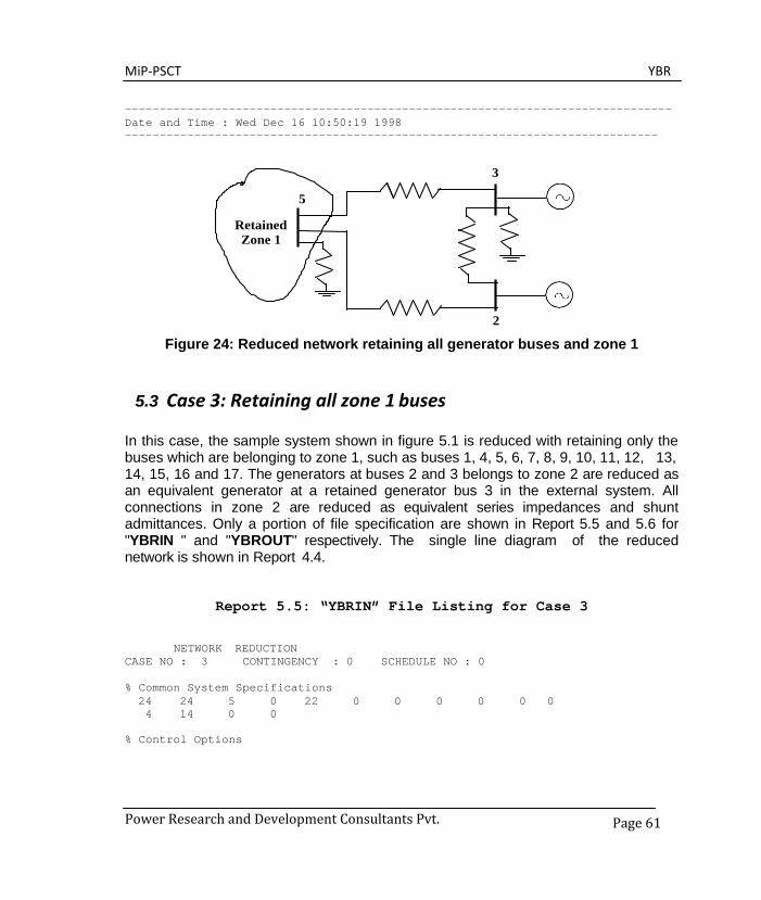
MiP-PSCT YBR
Power Research and Development Consultants Pvt.
Page 61
------------------------------------------------------------------------------- Date and Time : Wed Dec 16 10:50:19 1998 -----------------------------------------------------------------------------
2
Figure 24: Reduced network retaining all generator buses and zone 1
5.3 Case 3: Retaining all zone 1 buses
In this case, the sample system shown in figure 5.1 is reduced with retaining only the buses which are belonging to zone 1, such as buses 1, 4, 5, 6, 7, 8, 9, 10, 11, 12, 13, 14, 15, 16 and 17. The generators at buses 2 and 3 belongs to zone 2 are reduced as an equivalent generator at a retained generator bus 3 in the external system. All connections in zone 2 are reduced as equivalent series impedances and shunt admittances. Only a portion of file specification are shown in Report 5.5 and 5.6 for "YBRIN " and "YBROUT" respectively. The single line diagram of the reduced network is shown in Report 4.4.
Report 5.5: “YBRIN” File Listing for Case 3
NETWORK REDUCTION CASE NO : 3 CONTINGENCY : 0 SCHEDULE NO : 0
% Common System Specifications 24 24 5 0 22 0 0 0 0 0 0 4 14 0 0
% Control Options
3
5
Retained Zone 1

MiP-PSCT YBR
Power Research and Development Consultants Pvt.
Page 62
% 1. No of Areas 2. YBUS print Option % 3. BaseMVA 4. Nominal Freq 5. PreFaultOpt
2 3 100.000000 50.0000 1
% 6. ZoneNo Retained 7. ZBUS Print Option % 8. YBUS Reduction Option
1 3 1
% External System % No of Generators in External System % Reference Bus in External System 2 3
% CBResistance CBReactance Trans R/X 0.000000 0.000100 0.050000
% Multiplication Factors % 1. Transformer Zero Seq Impedance Factor % 2. No Of Voltage Levels % i. Transmission Line Voltage % ii. Transmission Line Zero Seq Res Mult Factor % iii. Transmission Line Zero Seq Rea Mult Factor % iv. Transmission Line Zero Seq Adm Mult Factor % 3. Generator Negative Seq Resistance Mult Fact % 4. Generator Negative Seq Reactance Mult Fact % 5. Generator Zero Seq Resistance Mult Fact % 6. Generator Zero Seq Reactance Mult Fact % 7. Load Negative Seq Imp Mult Fact % 8. Load Zero Seq Imp Mult Fact % 9. Series Reactor Zero Seq Imp Mult Fact %10. Shunt Reactor Zero Seq Imp Mult Fact 0.90000 3 11.0000 2.5000 2.5000 0.0250
220.0000 2.5000 2.5000 0.0250 400.0000 2.5000 2.5000 0.0250
0.1750 0.1750 0.0375 0.0375 0.8100 1.6000 1.0000 0.6250
%% Below data not given %% above data not given
% External Machine Data % BusNo Inertia
2 11.413 3 11.413
Report 5.6: “YBROUT” File Listing for Case 3
----------------------------------------------------------------------------- Date and Time: Wed Dec 16 11:11:34 1998 -------------------------------------------------------------------------------

MiP-PSCT YBR
Power Research and Development Consultants Pvt.
Page 63
NETWORK REDUCTION CASE NO: 13 CONTINGENCY : 0 SCHEDULE NO : 0
----------------------------------------------------------------------------- TOTAL NUMBER OF BUSES : 24 ACTUAL NUMBER OF BUSES : 24 NUMBER OF 2 WIND. TRANSFORMERS : 5 NUMBER OF 3 WIND. TRANSFORMERS : 0 NUMBER OF TRANSMISSION LINES : 22 NUMBER OF SERIES REACTORS : 0 NUMBER OF SERIES CAPACITORS : 0 NUMBER OF BUS COUPLERS : 0 NUMBER OF SHUNT REACTORS : 0 NUMBER OF SHUNT CAPACITORS : 0 NUMBER OF SHUNT IMPEDANCES : 0 NUMBER OF GENERATORS : 4 NUMBER OF LOADS : 14 NUMBER OF FILTERS : 0 NUMBER OF HVDC CONVERTORS : 0
----------------------------------------------------------------------------- NUMBER OF ZONES : 2 PRINT OPTION : 3 (BOTH DATA AND RESULTS PRINT) BASE MVA : 100.000 NOMINAL SYSTEM FREQUENCY: 50.000 PREFAULT VOLTAGE OPTION : 1 (READ FROM THE FILE) ZONE NUMBER RETAINED : 1 ZBUS PRINT OPTION : 3 YBUS REDUCTION OPTION : 1 (NETWORK REDUCTION) ----------------------------------------------------------------------------- NUMBER OF GENERATORS IN THE EXTERNAL SYSTEM : 2 RETAINED GENERATOR BUS IN THE EXTERNAL SYSTEM : 3
----------------------------------------------------------------------------- CIRCUIT BREAKER RESISTANCE (PU) : 0.000000 CIRCUIT BREAKER REACTANCE (PU) : 0.000100 TRANSFORMER R/X RATIO : 0.050000 TRANSFORMER ZERO SEQUENCE IMPEDANCE MULT FACTOR : 0.900000
NUMBER OF TRANSMISSION VOLTAGE LEVELS : 3 TRANSMISSION LINE VOLTAGE - KV : 11.000000 TRANSMISSION LINE ZERO SEQUENCE RES. MULT. FACTOR : 2.500000 TRANSMISSION LINE ZERO SEQUENCE REA. MULT. FACTOR : 2.500000 TRANSMISSION LINE ZERO SEQUENCE ADM. MULT. FACTOR : 0.025000 TRANSMISSION LINE VOLTAGE - KV : 220.000000 TRANSMISSION LINE ZERO SEQUENCE RES. MULT. FACTOR : 2.500000 TRANSMISSION LINE ZERO SEQUENCE REA. MULT. FACTOR : 2.500000 TRANSMISSION LINE ZERO SEQUENCE ADM. MULT. FACTOR : 0.025000 TRANSMISSION LINE VOLTAGE - KV : 400.000000 TRANSMISSION LINE ZERO SEQUENCE RES. MULT. FACTOR : 2.500000 TRANSMISSION LINE ZERO SEQUENCE REA. MULT. FACTOR : 2.500000 TRANSMISSION LINE ZERO SEQUENCE ADM. MULT. FACTOR : 0.025000
GENERATOR NEGATIVE SEQUENCE RESISTANCE MULT. FACTOR : 0.175000 GENERATOR NEGATIVE SEQUENCE REACTANCE MULT. FACTOR : 0.175000 GENERATOR ZERO SEQUENCE RESISTANCE MULT. FACTOR : 0.037500
MiP-PSCT YBR
Power Research and Development Consultants Pvt.
Page 64
GENERATOR ZERO SEQUENCE REACTANCE MULT. FACTOR : 0.037500 LOAD NEGATIVE SEQUENCE IMPEDANCE MULT. FACTOR : 0.810000 LOAD ZERO SEQUENCE IMPEDANCE MULT. FACTOR : 1.600000 SERIES REACTOR ZERO SEQUENCE IMPEDANCE MULT. FACTOR : 1.000000 SHUNT REACTOR ZERO SEQUENCE IMPEDANCE MULT. FACTOR : 0.625000 ----------------------------------------------------------------------------- ----------------------------------------------------------------------------- %%Below results not given %% above results not given ----------------------------------------------------------------------------- EXTERNAL GENERATOR DATA SLNO BUSNO NAME INERTIA-H-PU ---- ----- -------- ------------
1 2 BUS2 11.413 2 3 BUS3 11.413
Number of reduced buses : 4 Reduced bus array : 26 25 19 24
----------------------------------------------------------------------------- %% below results not given %% above results not given ------------------------------------------------------------------------------- --- RETAINED ZONE : 1 NUMBER OF SERIES ELEMENTS IN THE REDUCED ZONES : 3 SERIES CONNECTIONS SLNO FROM NAME TO NAME RP XP BP/2 RZ XZ BZ/2 ---- ---- ------- ----- -------- -------- -------- ------- ----------- -----
1 26 GEN3 19 BUS19 0.005764 0.110167 0.0 0.035423 0.769343 0.0
2 26 GEN3 24 BUS24 0.032432 0.587300 0.0 0.062020 1.347784 0.0
3 19 BUS19 24 BUS24 0.035152 0.187473 0.0 0.099468 0.620119 0.0 -----------------------------------------------------------------------------
NUMBER OF SHUNT ELEMENTS IN THE REDUCED ZONES : 3 SHUNT CONNECTIONS IN (G+JB) FORMAT - PU SLNO FROM NAME GP BP GZ BZ ---- ---- -------- -------- -------- -------- --------
1 19 BUS19 1.90970 -0.24798 2.10356 -5.24444 2 24 BUS24 1.31295 -0.34366 1.20133 -0.48369 3 26 GEN3 0.82938 -0.61373 0.91641 -0.43791
------------------------------------------------------- EQUIVALENT GENERATOR INERTIA CONSTANT - PU : 22.82422 EQUIVALENT GENERATOR REAL POWER - MW : 315.55257 EQUIVALENT GENERATOR REACTIVE POWER - MVAR : 86.34824 EQUIVALENT GENERATOR TERMINAL VOLTAGE MAG : 1.00000 EQUIVALENT GENERATOR TERMINAL VOLTAGE ANG-D: 6.99686 EQUIVALENT GENERATOR RESISTANCE PU : 0.00000
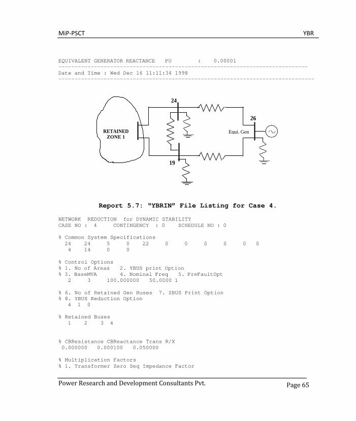
MiP-PSCT YBR
Power Research and Development Consultants Pvt.
Page 65
EQUIVALENT GENERATOR REACTANCE PU : 0.00001 ----------------------------------------------------------------------------- Date and Time : Wed Dec 16 11:11:34 1998 -------------------------------------------------------------------------------
Report 5.7: “YBRIN” File Listing for Case 4.
NETWORK REDUCTION for DYNAMIC STABILITY CASE NO : 4 CONTINGENCY : 0 SCHEDULE NO : 0
% Common System Specifications 24 24 5 0 22 0 0 0 0 0 0 4 14 0 0
% Control Options % 1. No of Areas 2. YBUS print Option % 3. BaseMVA 4. Nominal Freq 5. PreFaultOpt
2 3 100.000000 50.0000 1
% 6. No of Retained Gen Buses 7. ZBUS Print Option % 8. YBUS Reduction Option
4 1 0
% Retained Buses 1 2 3 4
% CBResistance CBReactance Trans R/X 0.000000 0.000100 0.050000
% Multiplication Factors % 1. Transformer Zero Seq Impedance Factor
24
26
RETAINED ZONE 1
Equi. Gen
19

MiP-PSCT YBR
Power Research and Development Consultants Pvt.
Page 66
% 2. No Of Voltage Levels % i. Transmission Line Voltage % ii. Transmission Line Zero Seq Res Mult Factor % iii. Transmission Line Zero Seq Rea Mult Factor % iv. Transmission Line Zero Seq Adm Mult Factor % 3. Generator Negative Seq Resistance Mult Fact % 4. Generator Negative Seq Reactance Mult Fact % 5. Generator Zero Seq Resistance Mult Fact % 6. Generator Zero Seq Reactance Mult Fact % 7. Load Negative Seq Imp Mult Fact % 8. Load Zero Seq Imp Mult Fact % 9. Series Reactor Zero Seq Imp Mult Fact %10. Shunt Reactor Zero Seq Imp Mult Fact 0.90000 3 11.0000 2.5000 2.5000 0.0250
220.0000 2.5000 2.5000 0.0250 400.0000 2.5000 2.5000 0.0250
0.1750 0.1750 0.0375 0.0375 0.8100 1.6000 1.0000 0.6250
%% remaining data not given
Report 5.8: “YBROUT” File Listing for Case 4. --------------------------------------------------------------- ------------------------------------------------------ Date and Time : Wed Dec 16 12:50:34 1998 -----------------------------------------------------------------------------
NETWORK REDUCTION for DYNAMIC STABILITY CASE NO : 14 CONTINGENCY : 0 SCHEDULE NO : 0
----------------------------------------------------------------------------- TOTAL NUMBER OF BUSES : 24 ACTUAL NUMBER OF BUSES : 24 NUMBER OF 2 WIND. TRANSFORMERS : 5 NUMBER OF 3 WIND. TRANSFORMERS : 0 NUMBER OF TRANSMISSION LINES : 22 NUMBER OF SERIES REACTORS : 0 NUMBER OF SERIES CAPACITORS : 0 NUMBER OF BUS COUPLERS : 0 NUMBER OF SHUNT REACTORS : 0 NUMBER OF SHUNT CAPACITORS : 0 NUMBER OF SHUNT IMPEDANCES : 0 NUMBER OF GENERATORS : 4 NUMBER OF LOADS : 14 NUMBER OF FILTERS : 0 NUMBER OF HVDC CONVERTORS : 0
----------------------------------------------------------------------------- NUMBER OF ZONES : 2 PRINT OPTION : 3 (BOTH DATA AND RESULTS PRINT) BASE MVA : 100.000 NOMINAL SYSTEM FREQUENCY: 50.000 PREFAULT VOLTAGE OPTION : 1 (READ FROM THE FILE) TOTAL BUSES IN THE REDUCED SYSTEM : 4 ZBUS PRINT OPTION : 0

MiP-PSCT YBR
Power Research and Development Consultants Pvt.
Page 67
YBUS REDUCTION OPTION : 0 (DYNAMIC STABILITY STUDY) ----------------------------------------------------------------------------- BUSES : 1 2 3 4 ----------------------------------------------------------------------------- %% below results not shown ............. ....... %% above results not shown Number of reduced buses : 4 Reduced bus array :
1 2 3 4 ----------------------------------------------------------------------------- POSITIVE SEQUENCE ADMITTANCE MATRIX ELEMENTS FOR THE GIVEN SYSTEM ----------------------------------------------------------------------------- ROW NO COLUMN NO REAL IMAGINARY ------ --------- ---------- ----------
1 1 4.84122 -12.15417 1 2 -0.00502 4.64545 1 3 0.05451 2.69446 1 4 1.13690 4.56290 2 1 -0.00502 4.64545 2 2 1.01332 -6.70635 2 3 0.04604 1.48618 2 4 0.08059 0.35653 3 1 0.05451 2.69446 3 2 0.04604 1.48618 3 3 1.46098 -4.75623 3 4 0.05115 0.20579 4 1 1.13690 4.56290 4 2 0.08059 0.35653 4 3 0.05115 0.20579 4 4 2.05991 -5.37231
----------------------------------------------------------------------------- NEGATIVE SEQUENCE ADMITTANCE MATRIX ELEMENTS FOR THE GIVEN SYSTEM ----------------------------------------------------------------------------- ROW NO ------
COLUMN NO ---------
REAL ----------
IMAGINARY ----------
1 1 4.84122 -12.15417 1 2 -0.00502 4.64545 1 3 0.05451 2.69446 1 4 1.13690 4.56290 2 1 -0.00502 4.64545 2 2 1.01332 -6.70635 2 3 0.04604 1.48618 2 4 0.08059 0.35653 3 1 0.05451 2.69446 3 2 0.04604 1.48618 3 3 1.46098 -4.75623 3 4 0.05115 0.20579 4 1 1.13690 4.56290 4 2 0.08059 0.35653
MiP-PSCT YBR
Power Research and Development Consultants Pvt.
Page 68
4 3 0.05115 0.20579 4 4 2.05991 -5.37231
----------------------------------------------------------------------------- ZERO SEQUENCE ADMITTANCE MATRIX ELEMENTS FOR THE GIVEN SYSTEM ----------------------------------------------------------------------------- ROW NO ------
1
COLUMN NO ---------
1
REAL ----------
3.12541
IMAGINARY ---------- -6.30191
1 2 -0.00604 2.31144 1 3 0.08009 0.91596 1 4 0.88516 1.65941 2 1 -0.00604 2.31144 2 2 0.85075 -3.58946 2 3 0.05142 0.74282 2 4 0.03145 0.05832 3 1 0.08009 0.91596 3 2 0.05142 0.74282 3 3 1.27050 -2.37628 3 4 0.01454 0.02198 4 1 0.88516 1.65941 4 2 0.03145 0.05832 4 3 0.01454 0.02198 4 4 1.84500 -3.08517
----------------------------------------------------------------------------- Date and Time: Wed Dec 16 12:50:34 1998 -----------------------------------------------------------------------------
Y
x Free Programmable
Block
R
Graph Utility
A
+ - x ÷
Power System Network Editor
COMTRADE Viewer
Database Manager
LPC/CPC
Power Research & Development Consultants Pvt. Ltd. # 5, 11th Cross, 2nd Stage, West of Chord Road, Bengaluru India - 560086.
Tel: +91-80-4245 5555 / 23192209, Fax: +91-80-4245 5556 / 23192210
Email: [email protected] website: www.prdcinfotech.com
© 2016 by Power Research & Development Consultants Pvt. Ltd. All rights reserved.
All information contained in this documentation, as well as the software described in it, is confidential and proprietary to Power Research & Development Consultants Pvt. Ltd. or one of its subsidiaries, is subject to a license agreement, and may be used or copied only in accordance with the terms of such license. Except as permitted by such license, no part of this documentation may be reproduced, stored in a retrieval system, or transmitted in any form or by electronic, mechanical, recording, or any other means, without the prior written permission of Power Research & Development Consultants Pvt. Ltd or one of its subsidiaries. Power Research & Development Consultants Pvt. Ltd. and the PRDC product names are trademarks or registered trademarks of Power Research & Development Consultants Pvt. Ltd., or one of its subsidiaries.