Foreword In this training manual we will study the fundamental principles of automotive transmissions transaxle and the clutch This course offers the fundamentals and must be used in conjunction with Suzuki service manuals for product specific information and specifications
Suzuki Technician curriculum This training manual is part of the Non Suzuki Technician to Suzuki Technician curriculum The curriculum consists of the following modules 1 GE01 Suzuki Introduction 2 GE02 Electrical Electronics 3 GE03 Diagnostics 4 EN02 Engine Mechanical part I 5 EN03 Engine Mechanical part II 6 EN04 Engine Mechanical part III 7 EN05 Engine Auxiliary systems 8 DS01 DriveshaftAxle 9 DS02 DriveshaftAxle - transfer case 10 BR02 Brake control systems 11 TR02 Manual transmission transaxle 12 CS02 Control system body electrical 13 CS03 Communication bus systems You are currently studying TR02 Manual Transmissiontransaxle This module consists of the following courses bull TR02 Manual transmission amp transaxle bull TR02 Practical Activities
This document is intended solely for training purposes only All vehicle repairs and adjustments must be carried out according to the procedures stipulated in current service manuals and technical bulletins
Smart manuals Some sections of this training manual contain videos with detailed information on the topics you are studying If you are studying this training manual on a PC look out for the ldquogreen play videordquo symbol on any photo or picture in this manual click on the green button to watch a video providing you with detailed information on that topic Note Internet connection required
TR01 Manual transmission amp transaxle 2
Table of contents Topic Page Manual transmission fundamentals 4 Overview 5 Transmission functions 5 Structure and operation 6 Power transmission 6 Neutral position 6 Gear change 7 Shift lever 10 Transmission operation 11 Synchromesh mechanism operation 12 Mechanisms for safe driving 14 Gear jump mechanism 14 Reverse gear shift lever 1-way movement mechanism 15 Interlock mechanism 17 Inadvertent reverse operation prevention mechanism 18 Input shaft brake system (IBS) 20 IBS operation 21 Suzuki manual transmission amp transaxle 24 Suzuki Alto (AMF310) transaxle overview 25 Gear shift mechanism 26 5th amp Reverse Gear Shift Cam 26 Suzuki Swift (AZH) transaxle overview 28 Gear shift mechanism 29 Reverse Shift Prevention Mechanism Construction 30 Suzuki Grand Vitara (JB424) manual transmission 32
Topic Page RW420 amp A6B424 6MT overview 34 Transaxle components 35 Overhaul 36 Important points for disassembly 37 Checks of internal transmission parts 37 Important points for assembly 39 Failure diagnosis 39 Clutch 42 Clutch overview 43 Structure and operation 44 Clutch operating mechanism 47 Clutch master cylinder 48 Checks and maintenance 50 Failure diagnosis 53
TR01 Manual transmission amp transaxle 3
TR01 Manual transmission amp transaxle
Lesson 1 Manual transmission fundamentals
Objectives At the end of this lesson you will be able to bull Describe gear operating principles bull Explain the functions of the transmission bull Describe the operating principles of the transmission bull Describe the different types of gear shift mechanisms bull Explain the function of synchromesh mechanism bull Describe the operating principles of the different
mechanisms for safe driving bull Explain the operating principle of the IBS
4
TR01 Manual transmission amp transaxle
11 Overview When a vehicle starts off a large driving force is required even through the engine rotation speed is low When a vehicle is driven at high speed a high engine rotation speed is required even though the driving force is low The transmission enables the vehicle to meet these different requirements A vehicle must also operate smoothly across many driving conditions For example driving at high speed or slow speed climbing up or going down hills repeatedly stopping and starting off and reversing The transmission coverts engine rotation speed and engine torque in accordance with these driving conditions and transmits them to the drive wheels
12 Transmission functions (i) The transmission transmits force by meshing gears together
(ii) Increasing torque and increasing engine rotation speed
5
Figure 1 Power transmission
1
2
3
Figure 2 Increasing torque and increasing engine rotation speed
bull Speed increase (a larger gear rotates a smaller gear)
bull Increasing the engine rotation speed (force drops)
bull Changing gears
bull Speed reduction (a small gear rotates a larger gear)
bull Increasing the force (engine rotation speed drops)
TR01 Manual transmission amp transaxle
(iii) A gear is added to change the rotation direction (iv) The transmission cuts off the power transmission by disconnecting the gear meshing
13 Structure and operation
131 Power transmission A vehicle requires a large driving force when starting off and a high engine rotation speed when driving at high speed To achieve this the transmission varies the engine rotation speed and torque by changing the gear combinations (gear ratio) The engine power is transmitted to the transmission input shaft via the clutch The rotation of the input shaft is transmitted to the output shaft gear via the countershaft gears An output gear meshes to the output shaft through synchro-mechanisms The rotation from the countershaft is transmitted to the output shaft In other words the gear ratio is changed when the sleeve moves in accordance with the shift lever position and changes the gears on the output shaft
132 Neutral position When none of the gears on the output shaft mesh with the gears on the counter shaft the transmission is in the neutral condition This means that when the vehicle is stopped and the engine is idling the engine power rotates the input shaft countershaft and the gears on the output shaft but the output shaft does not rotate
a large gear) bull 4th gear - Direct connection (rotation is transmitted
unchanged) bull 5th gear - Speed increase (large gear rotates a small gear) bull Reverse gear - Reverse rotation (gear is added)
7
Figure 5 Power transmission
Figure 6 Gear change
TR01 Manual transmission amp transaxle
134 Gear ratio The gear ratio is the ratio between the input gear and output gear rotation speeds The gear ratio changes as the transmission reduces or increases the engine rotation speed with different gear combinations Gear ratio = = = For example when the engine operates at a constant torque and a constant speed if the gear ratio is high (a small gear rotates a large gear) then a high torque but a low engine rotation speed are transmitted to the tires If the gear ratio is low a low torque and a high engine rotation speed are transmitted to the tires In this way the relationship between the transmitted torque and engine rotation speed is determined by the ratio of meshed gear teeth This means that the torque and the engine rotation speed can be expressed as follows Engine torque X gear ratio = output shaft torque = Output shaft rotation speed
8
No of output gears
No of input gears
Input gear RPM
Output gear RPM
Output shaft torque
Input shaft torque
Engine rotation speed
Gear ratio
Figure 7 Gear ratios
In the time that a large gear with 20 teeth rotates once a small gear with 10 teeth rotates twice In other words the small gear rotates at twice the speed of the large gear but transmits only half the force
TR01 Manual transmission amp transaxle
A gear is added to reverse the direction of rotation
135 Shift lever The shift lever can be moved horizontally to select the gear row (select movement) forward and back to move the gears (shift movement) These movements move the internal parts of the transmission to change gear
1351 Remote control type In remote control type a rod or cable connects the shift lever to the transmission This type minimizes vibration and noise because its use of anti-vibration rubber makes it difficult for engine vibration to be transmitted
1352 Direct shift type In direct shift type the shift lever is directly connected to the transmission Most rear wheel drive vehicles use this system because it delivers fast shift operations and feels good to operate
10
Figure 9 Rod type shift mechanism
Figure 10 Cable type shift mechanism
TR01 Manual transmission amp transaxle
14 Transmission operation
141 Gear change The movement of the shift lever is transmitted unchanged to the gear shift selector lever inside the transmission When the gear shift selector lever moves in the vertical direction shown in the figure to select and rotate a gear it moves the synchronizer hub and meshes the gear with the main shaft
142 What is the synchromesh mechanism The synchromesh mechanism selects the gear to mesh with the main shaft by moving the synchronizer sleeve When in neutral the gears on the main shaft rotate at a speed that is a multiple of the teeth ratio (reduction ratio) of the gears that oppose the rotation speed of the countershaft This means that the output shaft rotation speed and the rotation speeds of the gears on the output shaft are different When the gears are changed the synchromesh mechanism absorbs this rotation difference to ensure a smooth change
11
Figure 10 Direct shift mechanism
TR01 Manual transmission amp transaxle
143 Synchromesh mechanism operation 1st stage synchronization action 1 When the shift fork moves the synchronizer sleeve
(referred to as ldquosleeverdquo from now on) the sleeve and the meshed key move together to the right
2 The end of the key pushes the ring against the cone This frictional force transmits the rotation force of the sleeve to the gear
3 At this time the difference between the rotation speeds of the ring and gear and the friction with the cone shifts the rotation direction of the gear just by the difference between the key groove width and the key width As such when seen from above the splines on the inside of the sleeve and the ends of the ring splines face each other in different positions as shown in Figure 12
12
Figure 11 Synchronizer mechanism
Figure 12 Synchronizer mechanism operation
TR01 Manual transmission amp transaxle
2nd stage synchronization action 1 As the shift lever is moved the force acting on the sleeve
overcomes the spring The sleeve goes over the key protrusion and moves forward (moves to the right in the figure)
2 The splines on the inside of the sleeve and the ring splines hit against each other
3 The force applied to the sleeve is transmitted via the splines that continue to hit and contact each other and strongly pushes the ring into the gear cone This frictional force performs a strong synchronization action
3rd stage synchronization meshing 1 The sleeve and gear rotation speeds are equalized and the
ring is freed in the rotation direction 2 As shown in the figure below the splines on the inside of
the sleeve push away the ring splines and move smoothly to mesh with the gear splines
3 If there is a rotation difference between the ring or gear and the sleeve the frictional force of the ring and the gear cone stops the forward movement of the sleeve It only allows forward movement after synchronization is completed However when the synchronization action (frictional force) is weak there is a gear noise when meshing with the gear and gear shifting is difficult
13
Figure 13 Synchronizer mechanism operation
Figure 14 Synchronizer mechanism operation
TR01 Manual transmission amp transaxle
144 Mechanisms for safe driving A manual transmission has various mechanisms for safe driving These include a mechanism for preventing a meshed gear from jumping out while driving a mechanism for preventing more than one gear from meshing to the main shaft at the same time and a mechanism for preventing the vehicle from being mistakenly put into reverse while driving
1441 Gear jump mechanism ldquoGear jump outrdquo is when a gear jumps out without a shift operation It often occurs because of changes in vibration or load while driving such as during sudden acceleration or deceleration If the gear jumps out the transmission goes into neutral Gear jump out is often caused by gears meshing in a defective way at the moment of shifting or by a shift in the positional relationship between the sleeve and gear while driving due to wear on the splines between the synchronizer sleeve and the gear resulting in an excessive thrust clearance
(i) Chamfer The sleeve and gear spline fittings have tapered teeth surfaces During rotation the gear spline is driven by the tapered surface which makes it difficult for the gear to jump out
14
Figure 15 Chamfer method to prevent gear jump
TR01 Manual transmission amp transaxle
(ii) Detent ball The detent ball is pushed into the ball groove on the shift fork shaft by the spring This prevents gear jump out and gives a good operating feel when shifting
1442 Reverse gear shift lever 1-way movement mechanism In a manual transmission the shift lever is operated to move the various shift fork shafts The gear shift forks that are integrated with the shift fork shafts move to change the gears In recent Suzuki vehicles changing to reverse has been performed not by the sleeve movement but by the movement of the reverse idler gear Longitudinal manual transmissions use a reverse gear shift lever 1-way movement mechanism When a shift operation is made that involves a movement in the direction of the 5th gear side and the reverse side of the 5th-reverse shift fork the reverse gear shift lever 1-way movement mechanism is activated only when the reverse gear shift lever is operated to one side (reverse side) This mechanism moves the reverse idler gear
15
Figure 16 Detent ball method to prevent gear jump
TR01 Manual transmission amp transaxle
(i) When in neutral When in neutral because the pin of the 5th-reverse gear shift fork restricts the rotation of the reverse gear shift lever the reverse idler gear does not move
(ii) Reversing When shifting from neutral to reverse the pin of the 5th-reverse shift fork moves along the groove of the reverse gear shift lever applying force to the reverse gear shift lever in the clockwise direction The clockwise rotation of the reverse gear shift lever moves the reverse idler gear and fits it into the input shaft
16
Figure 17 Neutral position
Figure 18 Neutral position
TR01 Manual transmission amp transaxle
(iii) When in the 5th speed When shifting from neutral to the 5th gear the pin of the 5th-reverse gear shift fork moves inside the groove of the reverse gear shift lever but because rotation force is not applied to the reverse gear shift lever the reverse idler gear does not move
1443 Double meshing prevention mechanism (interlock mechanism) If 2 adjacent shift forks move at the same time there is a risk of 2 gears meshing To prevent this a double meshing prevention mechanism (interlock mechanism) is used (i) Transverse manual transmission When shifting to 1st or 2nd gear locking ball A that is pushed out by the low speed shift shaft moves the pin and locking ball B The balls enter the grooves of the high speed shift shaft and the 5th shift shaft to regulate the movement of these shift shafts
17
Figure 18 Neutral position
Figure 19 Double meshing prevention
TR01 Manual transmission amp transaxle
When shifting to 3rd or 4th gear the high speed shift shaft moves locking balls A and B which enter the grooves of the low speed shift shaft and the 5th shift shaft to regulate the movement in the shift direction When shifting to 5th or reverse gear locking ball B that is pushed out by the 5th shift shaft moves the pin and locking ball A The balls enter the grooves of the low speed shift shaft and the high speed shift shaft to regulate the movement in the shift direction
18
Figure 19 Double meshing prevention
1444 Inadvertent reverse operation prevention mechanism An inadvertent reverse gear operation is when the gear jumps out from 5th gear and through its own momentum enters the reverse gear To prevent this the mechanism is designed so that a shift to reverse gear cannot be made without first returning the shift lever to neutral Transverse manual transmission 1 When the shift lever is moved to the 5th gear the gear
shift selector shaft is pushed in the gear shift guide case direction At this time the movement of the 5th-reverse interlock plate is regulated by the guide bolt and the low select spring and the cam guide return spring are compressed
2 The 5th-reverse gear shift cam that shifts to 5th gear rotates and the reaction force of the cam guide return spring moves the 5th-reverse interlock plate one step to the rear
3 If shifting to reverse is performed in this condition the gear shift selector shaft rotates and the 5th-reverse gear shift cam continues to be pushed by the 5th-reverse interlock plate This means that the shifting cannot be performed Figure 21 Inadvertent reverse operation prevention mechanism
4 When the shift lever is returned to the neutral position the reaction force of the low select spring returns the 5th-reverse interlock plate to its normal position which allows shifting to reverse
1445 Input shaft brake system (IBS) When shifting into reverse even if you step on the clutch to cut off the power from the engine inertial force continues to rotate the input shaft This means that when shifting into reverse the reverse gear of the input shaft that continues to rotate and the reverse idler gear that is stationary are not synchronized This results in poor shifting into reverse gear and a gear noise To minimize this effect the IBS applies a brake to the input shaft with the 5th speed synchronizer ring to reduce the rotation speed and ensure a smooth shift into reverse
Figure 24 Without IBS (poor shifting and gear noise)
TR01 Manual transmission amp transaxle 21
(i) IBS structure The IBS is made up of a 5th speed synchronizer sleeve 5th speed synchronizer hub 5th speed synchronizer lever 5th speed synchronizer ring and input shaft 5th gear
(II) IBS operation bull When in neutral When the input shaft is rotating due to inertial force the 5th speed synchronizer sleeve and 5th speed synchronizer lever also rotate As such the 5th speed synchronizer lever pushes out toward the circumference due to centrifugal force This meshes the flange of the 5th speed synchronizer lever with the groove of the 5th speed synchronizer sleeve
Figure 25 With IBS (improved shifting reduced gear noise)
Figure 26 IBS structure
Figure 26 IBS operation neutral position
TR01 Manual transmission amp transaxle 22
bull Start of synchronization When shifting into reverse the 5th gear shift fork moves the 5th speed synchronizer sleeve in the direction of arrow A At this time the 5th speed synchronizer lever moves the flange of the 5th speed synchronizer lever in the direction of arrow B (figure 28) with the 5th speed synchronizer hub as the fulcrum because the 5th speed synchronizer hub is fixed to the input shaft This means that the 5th speed synchronizer lever pushes the 5th speed synchronizer ring so that the 5th speed
synchronizer ring and the cone surface of the input shaft 5th gear make contact This applies a brake to the input shaft reducing its speed As such it is easier for the reverse idler gear and the input shaft reverse gear to mesh enabling a smooth shift into reverse
Figure 27 IBS operation neutral position rotating components
Figure 28 IBS operation start of synchronization
TR01 Manual transmission amp transaxle 23
bull Gear change completion When the 5th speed synchronizer sleeve moves further in the direction of arrow A the 5th speed synchronizer lever is pushed in the direction of arrow C This eliminates the force of the 5th speed synchronizer lever pushing against the 5th speed synchronizer ring At this time the 5th speed synchronizer ring and the cone surface of the input shaft 5th gear separate which releases the brake that was applied to the input shaft This means that after the gear change is completed the input shaft can rotate again
Objectives At the end of this lesson you will be able to bull Explain the construction of the transmissions or transaxles
used in Suzuki vehicles bull Identify the different components of the transmissions or
transaxles bull Explain the operation of the gear change mechanisms used
in the different models
TR01 Manual transmission amp transaxle 25
21 Suzuki Alto AMF310 transaxle overview 211 Construction The transaxle provides five forward speeds and one reverse speed by means of three synchromesh devices and three shafts-input shaft countershaft and reverse gear shaft All forward gears are in constant mesh and reverse uses a sliding idler gear arrangement The low speed synchronizer sleeve amp hub is mounted on countershaft and engaged with countershaft 1st gear or 2nd gear while the high speed synchronizer sleeve amp hub is done on input shaft and engaged with input shaft 3rd gear or 4th gear The 5th speed synchronizer sleeve amp hub on input shaft is engaged with input shaft fifth gear mounted on the input shaft A double cone synchronizing mechanism is provided to 2nd gear synchromesh device for high performance of shifting to 2nd gear The countershaft turns the final gear and differential assembly thereby turning the front drive shafts which are attached to the front wheels
Figure 1 Manual transaxle (Alto AMF310)
Figure 1 [1] 5th speed synchronizer sleeve amp hub [2] Input shaft 5th gear [3] Input shaft 4th gear [4] High speed synchronizer sleeve and hub [5] Input shaft 3rd gear [6] Left case [7] Reverse gear shaft [8] Reverse idler gear [9] Input shaft [10] Right case [11] Side cover [12] Countershaft 5th gear [13] Countershaft 4th gear [14] Countershaft [15] Countershaft 3rd gear [16] Countershaft 2nd gear [17] Low speed synchronizer speed amp hub [18] Countershaft 1st gear [19] Final gear [20] Differential case
TR01 Manual transmission amp transaxle 26
212 Gear Shift Mechanism The gear shifting control system consists of the following main parts Movement of gear shift control lever assembly (16) is transmitted to gear shift amp select shaft assembly (10) through gear shift control cable (1) and gear select control cable (2)
[12] Gear shift interlock bolt [13] Gear shift amp select lever [14] Low speed gear shift shaft [15] High speed gear shift shaft [16] Gear shift control lever assembly
213 5th amp Reverse Gear Shift Cam 5th amp reverse gear shift cam cam guide return spring and 5th to reverse interlock guide bolt are provided to prevent the gear from being directly shifted from 5th to reverse
1 Figure 4 (A) When shift lever is at neutral position between 3rd and 4th gear 5th amp reverse gear shift cam (2) is under 5th to reverse interlock guide bolt (5) and can turn freely clockwise (to 3rd gear) and counterclockwise (to 4th gear)
[1] Gear shift amp select shaft [3] Cam guide return spring (expanded) [4] 1st amp 2nd select spring (expanded)
2 Figure 4(B) When shift lever is shifted toward right from neutral position gear shift amp select shaft (1) moves up but 5th amp reverse gear shift cam (2) is restricted by 5th to reverse interlock guide bolt (5) and cam guide return spring (3) is contracted
A B C D
Figure 4 5th and reverse gear shift cam
TR01 Manual transmission amp transaxle 28
3 Figure 4 (C) When shift lever is shifted to 5th gear gear shift amp select shaft (1) turns clockwise letting 5th amp reverse gear shift cam (2) off from 5th to reverse interlock guide bolt and pushed up by cam gear return spring (3) In this state movement of shift cam is restricted by 5th to reverse interlock guide bolt (5) and therefore gearshift to reverse is not attainable 3 Figure 4 (D) When shift lever is shifted from neutral position between 3rd-4th gear to 5th amp reverse gear position gear shift amp select shaft (1) moves up but 5th amp reverse gear shift cam (2) is restricted to move up by 5th to reverse interlock guide bolt (5) In this position shift amp select shaft can turn both clockwise (to 5th gear) and counterclockwise (to reverse gear) [3] Cam guide return spring (contracted) [4] 1st and 2nd select spring (contracted)
22 Suzuki Swift (AZH model) transaxle overview 221 Description The transaxle provides five forward speeds and one reverse speed by means of three synchromesh devices and three shafts bull Input shaft bull Countershaft and bull Reverse gear shaft All forward gears are in constant mesh and reverse uses a sliding idler gear arrangement The low speed sleeve amp hub is mounted on countershaft and engaged with countershaft 1st gear or 2nd gear while the high speed sleeve amp hub is mounted on input shaft and engaged with input shaft 3rd gear or 4th gear The 5th speed sleeve amp hub on input shaft is engaged with input shaft 5th gear mounted on the input shaft To prevent the cracking noise from the reverse gear when shifting transaxle gear into the reverse gear the reverse shift braking device is used This device utilizes the 5th synchromesh which is the lever synchro type to apply the brake on the input shaft rotation The double cone synchronizing mechanism is provided to 2nd gear synchromesh device for high performance of shifting to 2nd gear For servicing it is necessary to use genuine sealant or its equivalent on mating surfaces of transaxle case which is made of aluminum The case fastening bolts must be tightened to specified torque by means of torque wrench It is also important that all parts are thoroughly cleaned with cleaning fluid and air dried before reassembling
TR01 Manual transmission amp transaxle 29
Further care must be taken to adjust preload of countershaft taper roller bearings New synchronizer rings are prohibited from being lapped with respective gear cones by using lapping compound before they are assembled
221 Gear shift mechanism The gear shifting control system consists of the main parts shown in figure 5 Movement of gear shift control lever is transmitted to gear shift amp select shaft through gear shift and gear select cables
Figure 5 Gear shift mechanism ndash Suzuki Swift AZH414
Figure 5 [1] Gear shift control cable [2] Gear selector control cable [3] Select cable lever [4] Shift cable lever [5] 5th gear shift fork [6] Reverse gear shift lever [7] 5th amp reverse gear shift guide shaft [8] 5th amp reverse gear shift shaft [9] Gear shift amp select shaft assembly [10] Gear shift interlock bolt [11] Gear shift and select lever [12] Low speed gear shift shaft [13] High speed gear shift shaft [14] Gear shift control lever assembly
TR01 Manual transmission amp transaxle 30
222 Reverse Shift Prevention Mechanism Construction In the gear shift lever case the reverse shift limit yoke (2) which turns around reverse shift limit yoke (2) retainer is provided This reverse shift limit yoke (2) restricts the movement of gear shift amp select lever (1) to prevent erroneous reverse shifting
Operation 1 If shifting directly from 5th [a] to reverse [b] is attempted
the cubic part of the gear shift amp select lever (1) is blocked by the projection of the reverse shift limit yoke (2)
2 Then the cubic part of the gear shift amp select lever (1) pushes the projection of the reverse shift limit yoke (2) The reverse shift limit yoke (2) rotates and pushes the gear shift amp select lever (1) toward the neutral position
3 If the reverse shifting force is still applied to the shift lever the cubic part of the gear shift amp select lever (1) rides over the projection of the reverse shift limit yoke (2) and the gear is shifted into the 4th The reverse shift limit yoke (2) returns to its original position
23 Suzuki Grand Vitara (JB424) manual transmission
Figure 10 Manual transmission ndash JB424
TR01 Manual transmission amp transaxle 33
Overview The manual transmission consists of the input shaft output shaft countershaft and reverse shaft which are installed in the die-cast aluminum alloy case This transmission provides five forward speeds and one reverse speed The 1st 2nd 3rd and 4th speeds are for speed reduction drive 5th speed is for direct drive The low speed (1st and 2nd) synchronizer is mounted on the countershaft and engaged with the countershaft 1st or 2nd gear The high speed (3rd and 4th) synchronizer is mounted on the input shaft and engaged with the input shaft 3rd and 4th gear The 5th speed synchronizer is mounted on the input shaft and engaged with the output shaft The gear shift lever case is located at the upper behind the transmission case and has a cam which prevents direct gear shifting from the 5th speed gear into the reverse gear As the die-cast aluminum alloy case are sealed with liquid type gasket it is necessary to use genuine sealant or its equivalent on its mating surface when reassembling them Also the case fastening bolts must be tightened to specified torque by means of the torque wrench and tightening over or below the specified torque should be avoided
24 Suzuki SX4 (RW420) amp Kizashi A6B424 6 speed manual transaxle overview The transaxle provides six forward speeds and one reverse speed by means of four synchromesh device (seven synchromesh devices in the A6B424) and three shafts bull input shaft bull counter shaft and bull reverse gear shaft The low speed sleeve amp hub is mounted on counter shaft and engaged with counter shaft 1st gear or 2nd gear while the high speed sleeve amp hub is done on input shaft and engaged with input shaft 3rd gear or 4th gear The 5th amp 6th speed sleeve amp hub is mounted on input shaft and engaged with input shaft 5th gear or 6th gear The reverse gear sleeve amp hub mounted on reverse gear shaft and engaged with reverse idler left gear or reverse idler right gear The triple cone synchronizing mechanism is provided to 1st and 2nd gear synchromesh devices for high performance of shifting to 2nd gear The double cone synchronizing mechanism is provided to 3rd gear synchromesh device for high performance of shifting For servicing it is necessary to use genuine sealant or its equivalent on mating surfaces of transaxle case It is also important that all parts are thoroughly cleaned with cleaning fluid and air dried before reassembling Further care must be taken to adjust between case and shaft to thrust clearance of input shaft and counter shaft Synchronizer rings are prohibited from being lapped with respective gear cones using lapping compound before they are assembled
241 Gear Shift Mechanism The gear shifting control system consists of the following main parts (shown in figure 11) Movement of gear shift control lever is transmitted to gear shift amp select shaft through gear shift and gear select cables
Figure 11 Gear shift mechanism ndash A6B424
[a] Vehicle forward [b] Direction of gear shift [c] Direction of gear select [1] Gear shift control lever knob [2] Gear shift control lever boot [3] Gear shift control cable [4] Gear select control lever [5] Gear shift control lever assembly [6] Gear shift amp select shaft assembly [7] Reverse gear shift lever [8] Gear shift interlock bolt
Objectives At the end of this lesson you will be able to bull Explain the important points that must be considered
during disassembly bull Describe the different checks for internal transmission
parts bull Explain the important points that must be considered
during transmission assembly bull Explain the different types of possible causes for different
transmission malfunctions
TR01 Manual transmission amp transaxle 37
31 Important points for disassembly There may be various reasons for disassembling the transmission such as abnormal noise or stiff shifting But before performing the disassembly you must first check for possible causes in locations other than the transmission unit For example if the shift operation is stiff if you disconnect the gear shift control cable on the transmission side and check the shift lever movement you can judge whether or not the cause is on the transmission side With some transmission types actual parts can be moved to identify the cause while only one side of the case is disconnected (before disassembling the transmission) These include the condition of the gear backlash and gear meshing the chattering of each shaft and the smoothness of the rotation of each gear and shaft During disassembly arrange the disassembled parts so that you remember to which system they belong Be especially careful of transmission internal parts because many of these parts have a specific assembly direction Make sure that you remember the correct assembly method by taking notes or marking the parts
32 Checks of internal transmission parts
321 Transmission case check Check mainly for cracks and that the breather plug functions properly If the plug is clogged clean it
322 Gear teeth surface check Check the gear teeth surfaces for excessive wear or damage If a gear is worn or damaged replace it because it may cause abnormal noise
323 Bearing check Clean the ball bearings and roller bearings and then rotate them Check that they operate smoothly and do not catch Also check the parts equivalent to the outer race and inner race in the taper roller bearing and replace them as a set if there are any problems Check the bushes for wear streaks and cracks and replace them as a set if there are any problems
324 Synchromesh mechanism check i If the clearance is equal to or below the specified value
when the synchronizer ring and its partner gear are pushed together replace the synchronizer ring Also if there is major wear on the gear cone replace as a set
TR01 Manual transmission amp transaxle 38
ii Replace if there is significant wear on the synchronizer key
protrusion Check for wear on the synchronizer sleeve that covers the protrusion
iii Replace if there is any breaking or attenuation on the key spring
325 Shift lever check Check for wear on the ball on the end of the shift lever and replace if there are any problems
326 Shift fork check Measure the thickness of each shift fork claw and the width of the synchronizer sleeve groove and replace if their values deviate from the standard
Figure 1 Synchromesh mechanism check
Figure 2 Shift fork check
TR01 Manual transmission amp transaxle 39
327 Check of parts in the interlock mechanism and gear jump out prevention mechanism Check parts such as the interlock pin spring and locking balls and replace if there are any problems such as damage attenuation or wear
33 Important points for assembly The important points for assembly are to make sure that the correct parts are installed in the correct areas in the correct direction and in the correct position Information such as the allowance of each part before disassembly and the force required for operations must be noted down in advance By performing this check in every stage you can prevent maintenance mistakes such as discovering after reassembly that the gears are too stiff to shift
34 Failure diagnosis The transmission is connected to the engine and its rotation speed changes in proportion to the vehicle speed and together with the differential and tires As such if a problem occurs the cause is not necessarily in the transmission When performing failure diagnosis for the transmission first the conditions and phenomena under which the problems occur must be checked and the structure understood The possible locations must then be narrowed down to find the cause
TR01 Manual transmission amp transaxle 40
341 Abnormal noise Most of the parts inside the transmission are sliding parts such as gears bearings and the synchro-mechanism If all parts in the transmission are covered by an oil film they will not wear But if wearing occurs chattering will occur in the sliding parts resulting in abnormal noise So in general the conditions under which the abnormal noise occurs must be identified and the operating parts that are related to these conditions must be checked Sometimes abnormal noise occurs only when driving with certain gears or only when shifting to certain gears above can be used to identify the problem But if the problem occurs across all driving ranges the cause may be in many different locations such as the differential wheel hub clutch propeller shaft and drive shaft
342 Gear engagement and disengagement problems Likely gear shift operation problems are (1) shift lever to gear shift control cable and (2) shift shaft to shift fork to synchro-mechanism When the transmission side of the gear shift control cable is disconnected and the shift lever is operated if the movement is stiff the problem is likely to be in system (1) above If the movement is light the problem is likely to be in system (2) During normal shift operation the driver steps on the clutch and the engine power is not transmitted to the transmission For this reason the same problems occur if the clutch is not fully disengaged 343 Gear jump out Gear jump out may occur more easily during a sudden forward movement Gear jump out may occur because of changes in vibration or load after the gears meshed in a defective way at the moment of shifting Or it may occur because part wearing caused a shift in the positional relationship between the synchronizer sleeve and gear To make a final identification of the cause the transmission must be disassembled To check shift to the gear that has the problem and make sure it is properly meshed Repeatedly perform sudden acceleration and deceleration to generate sudden forward movements and check the gear jump out phenomenon Also carefully check the shift feeling (operation feel weight) while operating the shift
TR01 Manual transmission amp transaxle 41
344 Oil leaks Clean the location where you suspect there is an oil leak Perform a driving test and check the oil leak location Be aware that breather clogging and overfilling may cause oil leaks
345 Manual transaxle symptom diagnosis
Figure 3 Oil level [3] oil filler hole
Condition Possible cause
Gears slipping out of mesh
Worn shift fork shaft
Worn shift fork or synchronizer sleeve
Wear or damaged locating springs
Worn bearings on input shaft or countershaft
Worn chamfered tooth on sleeve and gear
Hard shifting
Inadequate lubricant Improper clutch pedal free travel Distorted or broken clutch disk Damaged clutch pressure plate Worn synchronizer ring
Worn chamfered tooth on sleeve and gear
Worn gear shift control shaft joint bushing Distorted shift shaft
Broken gear shiftselect control cables
Noise
Inadequate or insufficient lubricant Damaged or worn bearings Damaged or worn gears
Damaged or worn synchronizer parts
TR01 Manual transmission amp transaxle 42
Lesson 4 Clutch
Objectives At the end of this lesson you will be able to bull Explain the function of the clutch and its components bull Describe the basic construction of clutch components bull Explain the different types of clutch release mechanisms bull Explain the function and operation of the clutch master
cylinder bull Describe how the clutch pedal height inspection is
performed bull Describe how the clutch release margin can be checked bull Describe how the cylinder push rod play can be checked bull Describe how the vehicle and be inspected to determine if
any clutch malfunction exists bull Using clutch wear pattern identify the possible cause of
clutch failure
TR01 Manual transmission amp transaxle 43
41 Overview Location The clutch is positioned between the engine and the transmission Function The clutch connects and disconnect the engine to the manual transmission When engaged the clutch transmits the engine power using the frictional force between the clutch disc and plate and the force that pushes down these parts The clutch is made up of an operation mechanism which transmits the operation force of the driver through a clutch cable or hydraulic pressure and a clutch unit that receives this force and connects and disconnects the power transmission
Figure 1 Clutch mechanism
TR01 Manual transmission amp transaxle 44
42 Structure and operation 421 Clutch unit 4211 Clutch unit structure The clutch unit components include a clutch disc clutch cover and release bearing A diaphragm spring and a pressure plate are assembled to the clutch cover They are fixed to a flywheel with bolts The clutch disc is installed between the flywheel and clutch cover (pressure plate) and is fitted into the transmission input shaft
and splines The clutch disc is press fitted between the flywheel and pressure plate by the spring force of the diaphragm spring In other words the engine power is transmitted to the transmission input shaft via the frictional force between the clutch disc flywheel and pressure plate 4212 Clutch disc structure bull Clutch disc Clutch facing which is a frictional material is riveted to both sides of the clutch disc There is a clutch hub in the center of the clutch disc into which the transmissionrsquos input shaft is inserted The clutch facing must have an appropriate friction coefficient Its friction coefficient must not change much with temperature variations bull Damper spring The clutch hub is sandwiched between plates to its front and rear and is constructed so that the clutch can move in a circle (rotation direction) via the damper spring It absorbs and dampens the rotation impact when the clutch is connected
Figure2 Clutch unit components
TR01 Manual transmission amp transaxle 45
Figure 3 Clutch disc structure
TR01 Manual transmission amp transaxle 46
4213 Diaphragm spring clutch operation When the clutch is connected the spring force of the diaphragm spring pushes the clutch disc strongly against the flywheel via the pressure plate This means that the clutch plate rotates together with the flywheel so that the power from the engine is always transmitted to the transmission When the driver steps on the clutch pedal to cut off the power the release fork pushes the release bearing against the end of the diaphragm spring At this time the pivot ring (wire ring) becomes the fulcrum and the diaphragm spring outer circumference bends back The retracting spring (retainer plate) moves the pressure plate to the right This creates a gap between the friction surfaces of the clutch disc the power from the engine is cut off Figure 4 Clutch connection amp disconnection
TR01 Manual transmission amp transaxle 47
43 Clutch operation mechanism 431 Mechanical operation mechanism In this system the clutch pedal and release fork are connected with a clutch cable When the driver steps on the clutch pedal (1) the clutch cable is pulled (2) (3) and the release fork pushes the release bearing onto the diaphragm spring (4) When the driver releases the clutch pedal the spring force of the return spring and diaphragm spring returns the release fork and clutch pedal to their home positions and power is transmitted to the transmission
432 Hydraulic operation mechanism The components of this system include a clutch pedal master cylinder release cylinder release fork and pipe The pedal force (1) (2) is transmitted by hydraulic pressure (3) to the release fork (4) The hydraulic operation mechanism delivers reliable operation that is light and smooth However it has a complex structure and if air enters the clutch fluid it results in improper operation in the same way as in the brake hydraulic system (becomes difficult to disengage the clutch) Attention must also be paid to the clutch fluid level
44 Master cylinder The master cylinder is made up of a cylinder section in which a piston slides a long distance and a reservoir tank that stores the clutch fluid The master cylinder generates the hydraulic pressure for operating the clutch To generate the hydraulic pressure when the driver steps a little on the clutch pedal the piston is pushed and the clutch fluid inside the cylinder is sent to the reservoir tank When the driver steps more on the clutch pedal the piston moves and releases the connecting rod which up to now had been pulled by the spring retainer The spring force of the small conical spring that is built in to the connecting rod moves the inlet valve to the left and cuts off the inlet return common port
At the same time the fluid pressure inside the cylinder rises rapidly The clutch fluid is sent to the operating cylinder and moves the release piston When the driver releases the clutch pedal the piston is returned by the spring force of the return spring and the hydraulic pressure drops This makes the clutch fluid return from the operating cylinder side Also because the spring retainer pulls the connecting rod the inlet valve opens the inlet return common port This connects the reservoir tank with the master cylinder and the master cylinder is filled with clutch fluid
441 Operating cylinder The hydraulic pressure generated by the clutch master cylinder acts on the piston It acts as a force that moves the piston Also together with the tension from the piston spring it operates the clutch via the push rod and the release fork The bore of the operating cylinder is larger than the bore of the master cylinder which reduces the pedal force required when operating the clutch
Principle of leverage The ldquoprinciple of leveragerdquo is the way that a small force changes to a large force depending on the distance ratio between the fulcrum effort (point of force) and load (point of operation) This ldquoprinciple of leveragerdquo applies to the clutch pedal release fork and diaphragm spring This means that the long but light movement of the clutch pedal can be used to operate the short but heavy movement of the pressure plate
Figure 9 Clutch master cylinder
TR01 Manual transmission amp transaxle 50
Pascalrsquos principle When pressure of a certain force per unit area is applied to one area of a fluid in a sealed container regardless of its shape the pressure is transmitted undiminished to all areas of the fluid When pressure is applied to a sealed fluid force of the same strength (force per unit area) is generated in all parts Using this ldquoPascalrsquos principlerdquo the force is increased by making the area of the operating cylinder larger than the master cylinder
45 Checks and maintenance 451 Clutch pedal inspection (NB AZH models used for description) 4511 Clutch pedal height inspection Measure distance between free position (1) and fully depressed position (2) on clutch pedal shown by ldquoardquo in figure If clutch pedal height is out of specification replace pedal arm andor clutch master cylinder (3)
Figure 10 Clutch pedal height inspection
TR01 Manual transmission amp transaxle 51
4512 Cylinder push rod play Press clutch pedal (1) gradually with finger stop when slight increase of resistance is felt and measure how much pedal has moved (shown by ldquoardquo in figure) If ldquoardquo is not within specification replace master cylinder (3) or pedal arm (2) 4513 Clutch Pedal Free Travel Depress clutch pedal (1) stop the moment clutch resistance is felt and measure how much pedal has moved (shown by ldquobrdquo in figure) If ldquobrdquo is not within specification check pedal arm (2) and master cylinder (3) and replace defective part
4514 Clutch Release Margin 1) Apply parking brake fully and block wheels 2) Start engine and keep engine at idle in neutral position 3) Without clutch pedal (1) depressed slightly push the shift
lever to reverse position until transaxle emits gear contact noise Do not shift the lever to reverse position
4) While listening to gear contact noise slowly depress clutch pedal (1) and stop it when gear contact noise died (release point)
Figure 11 Cylinder push rod play
Figure 12 Clutch release margin
TR01 Manual transmission amp transaxle 52
5) Measure distance between release point (4) and full stroke point (5) on clutch pedal (1) shown by ldquocrdquo in the figure If ldquocrdquo is not within specification air may be trapped in clutch system Bleed air from clutch system Upon completion of above inspection start engine and check clutch for proper operation
4525 Air bleeding of clutch system CAUTION bull Brake fluid (Clutch fluid) is extremely damaging to paint If
fluid should accidentally touch painted surface immediately wipe fluid from paint and clean painted surface
bull When operating the clutch pedal for air bleeding after releasing the clutch pedal be sure to wait 1 second or more before depressing it again Otherwise the oil seal of operating cylinder will be damaged resulting in oil leakage
Perform in the same way as air bleeding for the brake hydraulic system but also pay attention to the following bull During the air bleeding operation make sure that the fluid
level does not drop to half or less bull After bleeding the air tighten the bleeder plug to the
specified torque
Bleeder plug
TR01 Manual transmission amp transaxle 53
46 Failure diagnosis 461 Engagement defect To check for engagement defect first put the transmission into the 1st gear while stepping on the clutch pedal Next put the transmission into the neutral position step on the accelerator pedal to raise the engine rotation speed and then return the transmission to the 1st gear At this time continue stepping down on the clutch pedal If an abnormal noise (gear noise) occurs during the above operations you can diagnose the problem as engagement defect In the engagement defect check you must determine whether the engagement defect occurs because the movement distance of the pressure plate is too short or whether the engagement defect is caused by a clutch unit problem where the clutch disc cannot separate from the flywheel and pressure plate
462 Slipping If slipping occurs between the clutch disc and pressure plate it may impair the transmission of power from the engine to the transmission and cause acceleration problems For this reason be careful during diagnosis because this problem is easy to mistake for an engine failure Check carefully whether the origin of the problem is in the operation mechanism or the clutch unit Before performing the check pull up the parking brake place wheel blocks around the tires and fully stop the vehicle Then step on the clutch pedal put the transmission into the 4th gear and slowly connect the clutch while slowly raising the engine rotation speed If the engine stops at this time the clutch is in a good condition But if the engine does not stop and the vehicle does not move forward you can conclude that the clutch is slipping
TR01 Manual transmission amp transaxle 54
463 Unsmooth engagement Check carefully whether the cause is insufficient smoothness in the operation mechanism or uneven transmission torque caused by a defect in the clutch unit Check carefully because this may also cause the engine output to drop or other problems To perform the check start the engine step on the clutch pedal put the transmission into the 1st gear and slowly connect the clutch If there is no uncomfortable vibration at this time you can conclude that the clutch unit is in a good condition
464 Sudden forward movement (jumping out) Sudden forward movement is a symptom where the vehicle does not start off smoothly The vehicle may jump forward automatically when the clutch pedal is operated or the engine may feel like it will stop Check carefully whether the cause of the sudden forward movement is insufficient smoothness in the operation mechanism or uneven transmission torque caused by a defect in the clutch unit To perform the check start the engine put the transmission into the 1st gear or reverse and slowly connect the clutch If the vehicle does not start off suddenly you can conclude that the clutch unit is in a good condition
465 Abnormal noise Continuous abnormal noise may be caused by defects in the pilot bearing release bearing or input bearing or in bearings inside the transmission While the vehicle is stopped and the engine is operating if the abnormal noise stops when you step on the clutch pedal the defect is probably in a bearing inside the transmission If the abnormal noise does not stop at this time the defect is probably in the release bearing or the pilot bearing Sometimes a temporary abnormal noise is made during acceleration or deceleration while the clutch is engaged In such cases depending on the noise type and the conditions under which it occurs you must check not only the clutch and transmission but also parts such as the engine mount and drive belt
TR01 Manual transmission amp transaxle 55
Summary bull The clutch is used to connect and disconnect the engine
from the manual transmission bull The clutch disc consists of a splined hub and a round metal
plate covered with friction material bull The release bearing is usually a ball bearing and collar
assembly that reduces friction between the pressure plate levers and the clutch fork
bull A clutch release mechanism allows the driver to disconnect the clutch from the engine
bull The release mechanism can use either a cable or hydraulic pressure
bull A worn clutch disc will cause clutch slippage and sometimes damage the flywheel
bull A bad pressure plate can also cause clutch slippage and clutch release problems
bull A worn pilot bearing will allow the transmission input shaft and clutch disc to wobble up and down This can cause clutch vibration abnormal noises and damage to the transmission
bull Clutch slippage causes the engine to race (engine speed increases quickly) without an increase in the vehiclersquos road speed
Reference The following abbreviations can be used in this training manual A AB Air Bag ABDC After Bottom Dead Center ABS Anti-lock Brake System AC Alternating Current AC Air Conditioning A-ELR Automatic-Emergency Locking Retractor AF Air Fuel Ratio ALR Automatic Locking Retractor API American Petroleum Institute APP Accelerator Pedal Position AT Automatic Transmission Automatic Transaxle ATDC After Top Dead Center ATF Automatic Transmission Fluid Automatic Transaxle Fluid AWD All Wheel Drive API American Petroleum Industry B BARO Barometric Pressure BBDC Before Bottom Dead Center BCM Body electrical Control Module BTDC Before Top Dead Center B+ Battery Positive Voltage BB+ Battery Positive Voltage for Backup
C CAN Controller Area Network CKP Crankshaft Position CMP Camshaft Position CO Carbon Monoxide CO2 Carbon Dioxide CPP Clutch Pedal Position CPU Central Processing Unit CVT Continuously Variable Transmission Continuously Variable Transaxle D DC Direct Current DC Driving Cycle DLC Data Link Connector DOHC Double Over Head Camshaft DOJ Double Offset Joint DOT Department of Transportation DPFreg Diesel Particulate Filter DRL Daytime Running Light DTC Diagnostic Trouble Code (Diagnostic Code) DC Driving Cycle
TR01 Manual transmission amp transaxle 56
E EBD Electronic Brake Force Distribution ECM Engine Control Module ECT Engine Coolant Temperature ECU Electronic Control Unit EEPROM Electrically Erasable Programmable Read Only Memory EFE Heater Early Fuel Evaporation Heater EGR Exhaust Gas Recirculation EGT Exhaust Gas Temperature ELR Emergency Locking Retractor ENG A-Stop Engine Auto Stop Start EPS Electronic Power Steering ESPreg Electronic Stability Program EVAP Evaporative Emission G GND Ground GPS Global Positioning System GL Gear libricant H HVAC Heating Ventilating and Air Conditioning HC Hydrocarbons HFC Hydro Fluorocarbon HI High HO2S Heated Oxygen Sensor
I IAC Idle Air Control IAT Intake Air Temperature IMT Intake Manifold Tuning ISC Idle Speed Control ISO International Organization for Standardization J JIS Japanese Industrial Standards JB Junction Block JC Junction Connector L L Left LCD Liquid Crystal Display LED Light Emitting Diode LHD Left Hand Drive vehicle LIN Local Interconnect Network LO Low LSPV Load Sensing Proportioning Valve M MAF Mass Air Flow MAP Manifold Absolute Pressure Max Maximum MFI Multiport Fuel Injection Min Minimum MIL Malfunction Indicator Lamp (ldquoCHECK ENGINErdquo Light or ldquoSERVICE ENGINE SOONrdquo Light) MT Manual Transmission Manual Transaxle
TR01 Manual transmission amp transaxle 57
N NOx Nitrogen Oxides O OBD On-Board Diagnostic system OCM Occupant Classification Module OCV Oil Control Valve OD Overdrive OHC Over Head Camshaft O2S Oxygen Sensor P PCM Powertrain Control Module PCV Positive Crankcase Ventilation PM Particulate Mater PNP Park Neutral Position PS Power Steering PSP Power Steering Pressure R R Right RAM Random Access Memory RHD Right Hand Drive Vehicle ROM Read Only Memory RPM Engine Speed S SAE Society of Automotive Engineers SDM Sensing and Diagnostic Module (Air Bag Controller Air bag Control Module) SDT Smart Diagnostic Tester SFI Sequential Multiport Fuel Injection SI System International SOHC Single Over Head Camshaft SRS Supplemental Restraint System
T TCC Torque Converter Clutch TCM Transmission Control Module TCSS Traction Control Support System TDC Top Dead Center TP Throttle Position TPMS Tire Pressure Monitoring System TWC Three-Way Catalytic converter U UART Universal Asynchronous Receiver Transmitter USB Universal Serial Bus V VFD Vacuum Fluorescent Display VIN Vehicle Identification Number VSS Vehicle Speed Sensor VVT Variable Valve Timing W WU-OC Warm Up Oxidation Catalytic converter WU-TWC Warm Up Three-Way Catalytic converter Other 2WD 2-Wheel Drive 4WD 4-Wheel Drive Note ESP is a trademark of Daimler AG DPFreg is a trademark of HJS Fahrzeugtechnik GmbH amp Co KG and Suzuki is the trade mark licensee
TR01 Manual transmission amp transaxle 58
Well done you have now completed the ldquoTR02 Manual transmission amp transaxlerdquo online training course
Please take the online exam
TR01 Manual transmission amp transaxle 59
Slide Number 1
Slide Number 2
Slide Number 3
Slide Number 4
Slide Number 5
Slide Number 6
Slide Number 7
Slide Number 8
Slide Number 9
Slide Number 10
Slide Number 11
Slide Number 12
Slide Number 13
Slide Number 14
Slide Number 15
Slide Number 16
Slide Number 17
Slide Number 18
Slide Number 19
Slide Number 20
Slide Number 21
Slide Number 22
Slide Number 23
Slide Number 24
Slide Number 25
Slide Number 26
Slide Number 27
Slide Number 28
Slide Number 29
Slide Number 30
Slide Number 31
Slide Number 32
Slide Number 33
Slide Number 34
Slide Number 35
Slide Number 36
Slide Number 37
Slide Number 38
Slide Number 39
Slide Number 40
Slide Number 41
Slide Number 42
Slide Number 43
Slide Number 44
Slide Number 45
Slide Number 46
Slide Number 47
Slide Number 48
Slide Number 49
Slide Number 50
Slide Number 51
Slide Number 52
Slide Number 53
Slide Number 54
Slide Number 55
Slide Number 56
Slide Number 57
Slide Number 58
Slide Number 59
TR01 Manual transmission amp transaxle
(iii) A gear is added to change the rotation direction (iv) The transmission cuts off the power transmission by disconnecting the gear meshing
13 Structure and operation
131 Power transmission A vehicle requires a large driving force when starting off and a high engine rotation speed when driving at high speed To achieve this the transmission varies the engine rotation speed and torque by changing the gear combinations (gear ratio) The engine power is transmitted to the transmission input shaft via the clutch The rotation of the input shaft is transmitted to the output shaft gear via the countershaft gears An output gear meshes to the output shaft through synchro-mechanisms The rotation from the countershaft is transmitted to the output shaft In other words the gear ratio is changed when the sleeve moves in accordance with the shift lever position and changes the gears on the output shaft
132 Neutral position When none of the gears on the output shaft mesh with the gears on the counter shaft the transmission is in the neutral condition This means that when the vehicle is stopped and the engine is idling the engine power rotates the input shaft countershaft and the gears on the output shaft but the output shaft does not rotate
a large gear) bull 4th gear - Direct connection (rotation is transmitted
unchanged) bull 5th gear - Speed increase (large gear rotates a small gear) bull Reverse gear - Reverse rotation (gear is added)
7
Figure 5 Power transmission
Figure 6 Gear change
TR01 Manual transmission amp transaxle
134 Gear ratio The gear ratio is the ratio between the input gear and output gear rotation speeds The gear ratio changes as the transmission reduces or increases the engine rotation speed with different gear combinations Gear ratio = = = For example when the engine operates at a constant torque and a constant speed if the gear ratio is high (a small gear rotates a large gear) then a high torque but a low engine rotation speed are transmitted to the tires If the gear ratio is low a low torque and a high engine rotation speed are transmitted to the tires In this way the relationship between the transmitted torque and engine rotation speed is determined by the ratio of meshed gear teeth This means that the torque and the engine rotation speed can be expressed as follows Engine torque X gear ratio = output shaft torque = Output shaft rotation speed
8
No of output gears
No of input gears
Input gear RPM
Output gear RPM
Output shaft torque
Input shaft torque
Engine rotation speed
Gear ratio
Figure 7 Gear ratios
In the time that a large gear with 20 teeth rotates once a small gear with 10 teeth rotates twice In other words the small gear rotates at twice the speed of the large gear but transmits only half the force
TR01 Manual transmission amp transaxle
A gear is added to reverse the direction of rotation
135 Shift lever The shift lever can be moved horizontally to select the gear row (select movement) forward and back to move the gears (shift movement) These movements move the internal parts of the transmission to change gear
1351 Remote control type In remote control type a rod or cable connects the shift lever to the transmission This type minimizes vibration and noise because its use of anti-vibration rubber makes it difficult for engine vibration to be transmitted
1352 Direct shift type In direct shift type the shift lever is directly connected to the transmission Most rear wheel drive vehicles use this system because it delivers fast shift operations and feels good to operate
10
Figure 9 Rod type shift mechanism
Figure 10 Cable type shift mechanism
TR01 Manual transmission amp transaxle
14 Transmission operation
141 Gear change The movement of the shift lever is transmitted unchanged to the gear shift selector lever inside the transmission When the gear shift selector lever moves in the vertical direction shown in the figure to select and rotate a gear it moves the synchronizer hub and meshes the gear with the main shaft
142 What is the synchromesh mechanism The synchromesh mechanism selects the gear to mesh with the main shaft by moving the synchronizer sleeve When in neutral the gears on the main shaft rotate at a speed that is a multiple of the teeth ratio (reduction ratio) of the gears that oppose the rotation speed of the countershaft This means that the output shaft rotation speed and the rotation speeds of the gears on the output shaft are different When the gears are changed the synchromesh mechanism absorbs this rotation difference to ensure a smooth change
11
Figure 10 Direct shift mechanism
TR01 Manual transmission amp transaxle
143 Synchromesh mechanism operation 1st stage synchronization action 1 When the shift fork moves the synchronizer sleeve
(referred to as ldquosleeverdquo from now on) the sleeve and the meshed key move together to the right
2 The end of the key pushes the ring against the cone This frictional force transmits the rotation force of the sleeve to the gear
3 At this time the difference between the rotation speeds of the ring and gear and the friction with the cone shifts the rotation direction of the gear just by the difference between the key groove width and the key width As such when seen from above the splines on the inside of the sleeve and the ends of the ring splines face each other in different positions as shown in Figure 12
12
Figure 11 Synchronizer mechanism
Figure 12 Synchronizer mechanism operation
TR01 Manual transmission amp transaxle
2nd stage synchronization action 1 As the shift lever is moved the force acting on the sleeve
overcomes the spring The sleeve goes over the key protrusion and moves forward (moves to the right in the figure)
2 The splines on the inside of the sleeve and the ring splines hit against each other
3 The force applied to the sleeve is transmitted via the splines that continue to hit and contact each other and strongly pushes the ring into the gear cone This frictional force performs a strong synchronization action
3rd stage synchronization meshing 1 The sleeve and gear rotation speeds are equalized and the
ring is freed in the rotation direction 2 As shown in the figure below the splines on the inside of
the sleeve push away the ring splines and move smoothly to mesh with the gear splines
3 If there is a rotation difference between the ring or gear and the sleeve the frictional force of the ring and the gear cone stops the forward movement of the sleeve It only allows forward movement after synchronization is completed However when the synchronization action (frictional force) is weak there is a gear noise when meshing with the gear and gear shifting is difficult
13
Figure 13 Synchronizer mechanism operation
Figure 14 Synchronizer mechanism operation
TR01 Manual transmission amp transaxle
144 Mechanisms for safe driving A manual transmission has various mechanisms for safe driving These include a mechanism for preventing a meshed gear from jumping out while driving a mechanism for preventing more than one gear from meshing to the main shaft at the same time and a mechanism for preventing the vehicle from being mistakenly put into reverse while driving
1441 Gear jump mechanism ldquoGear jump outrdquo is when a gear jumps out without a shift operation It often occurs because of changes in vibration or load while driving such as during sudden acceleration or deceleration If the gear jumps out the transmission goes into neutral Gear jump out is often caused by gears meshing in a defective way at the moment of shifting or by a shift in the positional relationship between the sleeve and gear while driving due to wear on the splines between the synchronizer sleeve and the gear resulting in an excessive thrust clearance
(i) Chamfer The sleeve and gear spline fittings have tapered teeth surfaces During rotation the gear spline is driven by the tapered surface which makes it difficult for the gear to jump out
14
Figure 15 Chamfer method to prevent gear jump
TR01 Manual transmission amp transaxle
(ii) Detent ball The detent ball is pushed into the ball groove on the shift fork shaft by the spring This prevents gear jump out and gives a good operating feel when shifting
1442 Reverse gear shift lever 1-way movement mechanism In a manual transmission the shift lever is operated to move the various shift fork shafts The gear shift forks that are integrated with the shift fork shafts move to change the gears In recent Suzuki vehicles changing to reverse has been performed not by the sleeve movement but by the movement of the reverse idler gear Longitudinal manual transmissions use a reverse gear shift lever 1-way movement mechanism When a shift operation is made that involves a movement in the direction of the 5th gear side and the reverse side of the 5th-reverse shift fork the reverse gear shift lever 1-way movement mechanism is activated only when the reverse gear shift lever is operated to one side (reverse side) This mechanism moves the reverse idler gear
15
Figure 16 Detent ball method to prevent gear jump
TR01 Manual transmission amp transaxle
(i) When in neutral When in neutral because the pin of the 5th-reverse gear shift fork restricts the rotation of the reverse gear shift lever the reverse idler gear does not move
(ii) Reversing When shifting from neutral to reverse the pin of the 5th-reverse shift fork moves along the groove of the reverse gear shift lever applying force to the reverse gear shift lever in the clockwise direction The clockwise rotation of the reverse gear shift lever moves the reverse idler gear and fits it into the input shaft
16
Figure 17 Neutral position
Figure 18 Neutral position
TR01 Manual transmission amp transaxle
(iii) When in the 5th speed When shifting from neutral to the 5th gear the pin of the 5th-reverse gear shift fork moves inside the groove of the reverse gear shift lever but because rotation force is not applied to the reverse gear shift lever the reverse idler gear does not move
1443 Double meshing prevention mechanism (interlock mechanism) If 2 adjacent shift forks move at the same time there is a risk of 2 gears meshing To prevent this a double meshing prevention mechanism (interlock mechanism) is used (i) Transverse manual transmission When shifting to 1st or 2nd gear locking ball A that is pushed out by the low speed shift shaft moves the pin and locking ball B The balls enter the grooves of the high speed shift shaft and the 5th shift shaft to regulate the movement of these shift shafts
17
Figure 18 Neutral position
Figure 19 Double meshing prevention
TR01 Manual transmission amp transaxle
When shifting to 3rd or 4th gear the high speed shift shaft moves locking balls A and B which enter the grooves of the low speed shift shaft and the 5th shift shaft to regulate the movement in the shift direction When shifting to 5th or reverse gear locking ball B that is pushed out by the 5th shift shaft moves the pin and locking ball A The balls enter the grooves of the low speed shift shaft and the high speed shift shaft to regulate the movement in the shift direction
18
Figure 19 Double meshing prevention
1444 Inadvertent reverse operation prevention mechanism An inadvertent reverse gear operation is when the gear jumps out from 5th gear and through its own momentum enters the reverse gear To prevent this the mechanism is designed so that a shift to reverse gear cannot be made without first returning the shift lever to neutral Transverse manual transmission 1 When the shift lever is moved to the 5th gear the gear
shift selector shaft is pushed in the gear shift guide case direction At this time the movement of the 5th-reverse interlock plate is regulated by the guide bolt and the low select spring and the cam guide return spring are compressed
2 The 5th-reverse gear shift cam that shifts to 5th gear rotates and the reaction force of the cam guide return spring moves the 5th-reverse interlock plate one step to the rear
3 If shifting to reverse is performed in this condition the gear shift selector shaft rotates and the 5th-reverse gear shift cam continues to be pushed by the 5th-reverse interlock plate This means that the shifting cannot be performed Figure 21 Inadvertent reverse operation prevention mechanism
4 When the shift lever is returned to the neutral position the reaction force of the low select spring returns the 5th-reverse interlock plate to its normal position which allows shifting to reverse
1445 Input shaft brake system (IBS) When shifting into reverse even if you step on the clutch to cut off the power from the engine inertial force continues to rotate the input shaft This means that when shifting into reverse the reverse gear of the input shaft that continues to rotate and the reverse idler gear that is stationary are not synchronized This results in poor shifting into reverse gear and a gear noise To minimize this effect the IBS applies a brake to the input shaft with the 5th speed synchronizer ring to reduce the rotation speed and ensure a smooth shift into reverse
Figure 24 Without IBS (poor shifting and gear noise)
TR01 Manual transmission amp transaxle 21
(i) IBS structure The IBS is made up of a 5th speed synchronizer sleeve 5th speed synchronizer hub 5th speed synchronizer lever 5th speed synchronizer ring and input shaft 5th gear
(II) IBS operation bull When in neutral When the input shaft is rotating due to inertial force the 5th speed synchronizer sleeve and 5th speed synchronizer lever also rotate As such the 5th speed synchronizer lever pushes out toward the circumference due to centrifugal force This meshes the flange of the 5th speed synchronizer lever with the groove of the 5th speed synchronizer sleeve
Figure 25 With IBS (improved shifting reduced gear noise)
Figure 26 IBS structure
Figure 26 IBS operation neutral position
TR01 Manual transmission amp transaxle 22
bull Start of synchronization When shifting into reverse the 5th gear shift fork moves the 5th speed synchronizer sleeve in the direction of arrow A At this time the 5th speed synchronizer lever moves the flange of the 5th speed synchronizer lever in the direction of arrow B (figure 28) with the 5th speed synchronizer hub as the fulcrum because the 5th speed synchronizer hub is fixed to the input shaft This means that the 5th speed synchronizer lever pushes the 5th speed synchronizer ring so that the 5th speed
synchronizer ring and the cone surface of the input shaft 5th gear make contact This applies a brake to the input shaft reducing its speed As such it is easier for the reverse idler gear and the input shaft reverse gear to mesh enabling a smooth shift into reverse
Figure 27 IBS operation neutral position rotating components
Figure 28 IBS operation start of synchronization
TR01 Manual transmission amp transaxle 23
bull Gear change completion When the 5th speed synchronizer sleeve moves further in the direction of arrow A the 5th speed synchronizer lever is pushed in the direction of arrow C This eliminates the force of the 5th speed synchronizer lever pushing against the 5th speed synchronizer ring At this time the 5th speed synchronizer ring and the cone surface of the input shaft 5th gear separate which releases the brake that was applied to the input shaft This means that after the gear change is completed the input shaft can rotate again
Objectives At the end of this lesson you will be able to bull Explain the construction of the transmissions or transaxles
used in Suzuki vehicles bull Identify the different components of the transmissions or
transaxles bull Explain the operation of the gear change mechanisms used
in the different models
TR01 Manual transmission amp transaxle 25
21 Suzuki Alto AMF310 transaxle overview 211 Construction The transaxle provides five forward speeds and one reverse speed by means of three synchromesh devices and three shafts-input shaft countershaft and reverse gear shaft All forward gears are in constant mesh and reverse uses a sliding idler gear arrangement The low speed synchronizer sleeve amp hub is mounted on countershaft and engaged with countershaft 1st gear or 2nd gear while the high speed synchronizer sleeve amp hub is done on input shaft and engaged with input shaft 3rd gear or 4th gear The 5th speed synchronizer sleeve amp hub on input shaft is engaged with input shaft fifth gear mounted on the input shaft A double cone synchronizing mechanism is provided to 2nd gear synchromesh device for high performance of shifting to 2nd gear The countershaft turns the final gear and differential assembly thereby turning the front drive shafts which are attached to the front wheels
Figure 1 Manual transaxle (Alto AMF310)
Figure 1 [1] 5th speed synchronizer sleeve amp hub [2] Input shaft 5th gear [3] Input shaft 4th gear [4] High speed synchronizer sleeve and hub [5] Input shaft 3rd gear [6] Left case [7] Reverse gear shaft [8] Reverse idler gear [9] Input shaft [10] Right case [11] Side cover [12] Countershaft 5th gear [13] Countershaft 4th gear [14] Countershaft [15] Countershaft 3rd gear [16] Countershaft 2nd gear [17] Low speed synchronizer speed amp hub [18] Countershaft 1st gear [19] Final gear [20] Differential case
TR01 Manual transmission amp transaxle 26
212 Gear Shift Mechanism The gear shifting control system consists of the following main parts Movement of gear shift control lever assembly (16) is transmitted to gear shift amp select shaft assembly (10) through gear shift control cable (1) and gear select control cable (2)
[12] Gear shift interlock bolt [13] Gear shift amp select lever [14] Low speed gear shift shaft [15] High speed gear shift shaft [16] Gear shift control lever assembly
213 5th amp Reverse Gear Shift Cam 5th amp reverse gear shift cam cam guide return spring and 5th to reverse interlock guide bolt are provided to prevent the gear from being directly shifted from 5th to reverse
1 Figure 4 (A) When shift lever is at neutral position between 3rd and 4th gear 5th amp reverse gear shift cam (2) is under 5th to reverse interlock guide bolt (5) and can turn freely clockwise (to 3rd gear) and counterclockwise (to 4th gear)
[1] Gear shift amp select shaft [3] Cam guide return spring (expanded) [4] 1st amp 2nd select spring (expanded)
2 Figure 4(B) When shift lever is shifted toward right from neutral position gear shift amp select shaft (1) moves up but 5th amp reverse gear shift cam (2) is restricted by 5th to reverse interlock guide bolt (5) and cam guide return spring (3) is contracted
A B C D
Figure 4 5th and reverse gear shift cam
TR01 Manual transmission amp transaxle 28
3 Figure 4 (C) When shift lever is shifted to 5th gear gear shift amp select shaft (1) turns clockwise letting 5th amp reverse gear shift cam (2) off from 5th to reverse interlock guide bolt and pushed up by cam gear return spring (3) In this state movement of shift cam is restricted by 5th to reverse interlock guide bolt (5) and therefore gearshift to reverse is not attainable 3 Figure 4 (D) When shift lever is shifted from neutral position between 3rd-4th gear to 5th amp reverse gear position gear shift amp select shaft (1) moves up but 5th amp reverse gear shift cam (2) is restricted to move up by 5th to reverse interlock guide bolt (5) In this position shift amp select shaft can turn both clockwise (to 5th gear) and counterclockwise (to reverse gear) [3] Cam guide return spring (contracted) [4] 1st and 2nd select spring (contracted)
22 Suzuki Swift (AZH model) transaxle overview 221 Description The transaxle provides five forward speeds and one reverse speed by means of three synchromesh devices and three shafts bull Input shaft bull Countershaft and bull Reverse gear shaft All forward gears are in constant mesh and reverse uses a sliding idler gear arrangement The low speed sleeve amp hub is mounted on countershaft and engaged with countershaft 1st gear or 2nd gear while the high speed sleeve amp hub is mounted on input shaft and engaged with input shaft 3rd gear or 4th gear The 5th speed sleeve amp hub on input shaft is engaged with input shaft 5th gear mounted on the input shaft To prevent the cracking noise from the reverse gear when shifting transaxle gear into the reverse gear the reverse shift braking device is used This device utilizes the 5th synchromesh which is the lever synchro type to apply the brake on the input shaft rotation The double cone synchronizing mechanism is provided to 2nd gear synchromesh device for high performance of shifting to 2nd gear For servicing it is necessary to use genuine sealant or its equivalent on mating surfaces of transaxle case which is made of aluminum The case fastening bolts must be tightened to specified torque by means of torque wrench It is also important that all parts are thoroughly cleaned with cleaning fluid and air dried before reassembling
TR01 Manual transmission amp transaxle 29
Further care must be taken to adjust preload of countershaft taper roller bearings New synchronizer rings are prohibited from being lapped with respective gear cones by using lapping compound before they are assembled
221 Gear shift mechanism The gear shifting control system consists of the main parts shown in figure 5 Movement of gear shift control lever is transmitted to gear shift amp select shaft through gear shift and gear select cables
Figure 5 Gear shift mechanism ndash Suzuki Swift AZH414
Figure 5 [1] Gear shift control cable [2] Gear selector control cable [3] Select cable lever [4] Shift cable lever [5] 5th gear shift fork [6] Reverse gear shift lever [7] 5th amp reverse gear shift guide shaft [8] 5th amp reverse gear shift shaft [9] Gear shift amp select shaft assembly [10] Gear shift interlock bolt [11] Gear shift and select lever [12] Low speed gear shift shaft [13] High speed gear shift shaft [14] Gear shift control lever assembly
TR01 Manual transmission amp transaxle 30
222 Reverse Shift Prevention Mechanism Construction In the gear shift lever case the reverse shift limit yoke (2) which turns around reverse shift limit yoke (2) retainer is provided This reverse shift limit yoke (2) restricts the movement of gear shift amp select lever (1) to prevent erroneous reverse shifting
Operation 1 If shifting directly from 5th [a] to reverse [b] is attempted
the cubic part of the gear shift amp select lever (1) is blocked by the projection of the reverse shift limit yoke (2)
2 Then the cubic part of the gear shift amp select lever (1) pushes the projection of the reverse shift limit yoke (2) The reverse shift limit yoke (2) rotates and pushes the gear shift amp select lever (1) toward the neutral position
3 If the reverse shifting force is still applied to the shift lever the cubic part of the gear shift amp select lever (1) rides over the projection of the reverse shift limit yoke (2) and the gear is shifted into the 4th The reverse shift limit yoke (2) returns to its original position
23 Suzuki Grand Vitara (JB424) manual transmission
Figure 10 Manual transmission ndash JB424
TR01 Manual transmission amp transaxle 33
Overview The manual transmission consists of the input shaft output shaft countershaft and reverse shaft which are installed in the die-cast aluminum alloy case This transmission provides five forward speeds and one reverse speed The 1st 2nd 3rd and 4th speeds are for speed reduction drive 5th speed is for direct drive The low speed (1st and 2nd) synchronizer is mounted on the countershaft and engaged with the countershaft 1st or 2nd gear The high speed (3rd and 4th) synchronizer is mounted on the input shaft and engaged with the input shaft 3rd and 4th gear The 5th speed synchronizer is mounted on the input shaft and engaged with the output shaft The gear shift lever case is located at the upper behind the transmission case and has a cam which prevents direct gear shifting from the 5th speed gear into the reverse gear As the die-cast aluminum alloy case are sealed with liquid type gasket it is necessary to use genuine sealant or its equivalent on its mating surface when reassembling them Also the case fastening bolts must be tightened to specified torque by means of the torque wrench and tightening over or below the specified torque should be avoided
24 Suzuki SX4 (RW420) amp Kizashi A6B424 6 speed manual transaxle overview The transaxle provides six forward speeds and one reverse speed by means of four synchromesh device (seven synchromesh devices in the A6B424) and three shafts bull input shaft bull counter shaft and bull reverse gear shaft The low speed sleeve amp hub is mounted on counter shaft and engaged with counter shaft 1st gear or 2nd gear while the high speed sleeve amp hub is done on input shaft and engaged with input shaft 3rd gear or 4th gear The 5th amp 6th speed sleeve amp hub is mounted on input shaft and engaged with input shaft 5th gear or 6th gear The reverse gear sleeve amp hub mounted on reverse gear shaft and engaged with reverse idler left gear or reverse idler right gear The triple cone synchronizing mechanism is provided to 1st and 2nd gear synchromesh devices for high performance of shifting to 2nd gear The double cone synchronizing mechanism is provided to 3rd gear synchromesh device for high performance of shifting For servicing it is necessary to use genuine sealant or its equivalent on mating surfaces of transaxle case It is also important that all parts are thoroughly cleaned with cleaning fluid and air dried before reassembling Further care must be taken to adjust between case and shaft to thrust clearance of input shaft and counter shaft Synchronizer rings are prohibited from being lapped with respective gear cones using lapping compound before they are assembled
241 Gear Shift Mechanism The gear shifting control system consists of the following main parts (shown in figure 11) Movement of gear shift control lever is transmitted to gear shift amp select shaft through gear shift and gear select cables
Figure 11 Gear shift mechanism ndash A6B424
[a] Vehicle forward [b] Direction of gear shift [c] Direction of gear select [1] Gear shift control lever knob [2] Gear shift control lever boot [3] Gear shift control cable [4] Gear select control lever [5] Gear shift control lever assembly [6] Gear shift amp select shaft assembly [7] Reverse gear shift lever [8] Gear shift interlock bolt
Objectives At the end of this lesson you will be able to bull Explain the important points that must be considered
during disassembly bull Describe the different checks for internal transmission
parts bull Explain the important points that must be considered
during transmission assembly bull Explain the different types of possible causes for different
transmission malfunctions
TR01 Manual transmission amp transaxle 37
31 Important points for disassembly There may be various reasons for disassembling the transmission such as abnormal noise or stiff shifting But before performing the disassembly you must first check for possible causes in locations other than the transmission unit For example if the shift operation is stiff if you disconnect the gear shift control cable on the transmission side and check the shift lever movement you can judge whether or not the cause is on the transmission side With some transmission types actual parts can be moved to identify the cause while only one side of the case is disconnected (before disassembling the transmission) These include the condition of the gear backlash and gear meshing the chattering of each shaft and the smoothness of the rotation of each gear and shaft During disassembly arrange the disassembled parts so that you remember to which system they belong Be especially careful of transmission internal parts because many of these parts have a specific assembly direction Make sure that you remember the correct assembly method by taking notes or marking the parts
32 Checks of internal transmission parts
321 Transmission case check Check mainly for cracks and that the breather plug functions properly If the plug is clogged clean it
322 Gear teeth surface check Check the gear teeth surfaces for excessive wear or damage If a gear is worn or damaged replace it because it may cause abnormal noise
323 Bearing check Clean the ball bearings and roller bearings and then rotate them Check that they operate smoothly and do not catch Also check the parts equivalent to the outer race and inner race in the taper roller bearing and replace them as a set if there are any problems Check the bushes for wear streaks and cracks and replace them as a set if there are any problems
324 Synchromesh mechanism check i If the clearance is equal to or below the specified value
when the synchronizer ring and its partner gear are pushed together replace the synchronizer ring Also if there is major wear on the gear cone replace as a set
TR01 Manual transmission amp transaxle 38
ii Replace if there is significant wear on the synchronizer key
protrusion Check for wear on the synchronizer sleeve that covers the protrusion
iii Replace if there is any breaking or attenuation on the key spring
325 Shift lever check Check for wear on the ball on the end of the shift lever and replace if there are any problems
326 Shift fork check Measure the thickness of each shift fork claw and the width of the synchronizer sleeve groove and replace if their values deviate from the standard
Figure 1 Synchromesh mechanism check
Figure 2 Shift fork check
TR01 Manual transmission amp transaxle 39
327 Check of parts in the interlock mechanism and gear jump out prevention mechanism Check parts such as the interlock pin spring and locking balls and replace if there are any problems such as damage attenuation or wear
33 Important points for assembly The important points for assembly are to make sure that the correct parts are installed in the correct areas in the correct direction and in the correct position Information such as the allowance of each part before disassembly and the force required for operations must be noted down in advance By performing this check in every stage you can prevent maintenance mistakes such as discovering after reassembly that the gears are too stiff to shift
34 Failure diagnosis The transmission is connected to the engine and its rotation speed changes in proportion to the vehicle speed and together with the differential and tires As such if a problem occurs the cause is not necessarily in the transmission When performing failure diagnosis for the transmission first the conditions and phenomena under which the problems occur must be checked and the structure understood The possible locations must then be narrowed down to find the cause
TR01 Manual transmission amp transaxle 40
341 Abnormal noise Most of the parts inside the transmission are sliding parts such as gears bearings and the synchro-mechanism If all parts in the transmission are covered by an oil film they will not wear But if wearing occurs chattering will occur in the sliding parts resulting in abnormal noise So in general the conditions under which the abnormal noise occurs must be identified and the operating parts that are related to these conditions must be checked Sometimes abnormal noise occurs only when driving with certain gears or only when shifting to certain gears above can be used to identify the problem But if the problem occurs across all driving ranges the cause may be in many different locations such as the differential wheel hub clutch propeller shaft and drive shaft
342 Gear engagement and disengagement problems Likely gear shift operation problems are (1) shift lever to gear shift control cable and (2) shift shaft to shift fork to synchro-mechanism When the transmission side of the gear shift control cable is disconnected and the shift lever is operated if the movement is stiff the problem is likely to be in system (1) above If the movement is light the problem is likely to be in system (2) During normal shift operation the driver steps on the clutch and the engine power is not transmitted to the transmission For this reason the same problems occur if the clutch is not fully disengaged 343 Gear jump out Gear jump out may occur more easily during a sudden forward movement Gear jump out may occur because of changes in vibration or load after the gears meshed in a defective way at the moment of shifting Or it may occur because part wearing caused a shift in the positional relationship between the synchronizer sleeve and gear To make a final identification of the cause the transmission must be disassembled To check shift to the gear that has the problem and make sure it is properly meshed Repeatedly perform sudden acceleration and deceleration to generate sudden forward movements and check the gear jump out phenomenon Also carefully check the shift feeling (operation feel weight) while operating the shift
TR01 Manual transmission amp transaxle 41
344 Oil leaks Clean the location where you suspect there is an oil leak Perform a driving test and check the oil leak location Be aware that breather clogging and overfilling may cause oil leaks
345 Manual transaxle symptom diagnosis
Figure 3 Oil level [3] oil filler hole
Condition Possible cause
Gears slipping out of mesh
Worn shift fork shaft
Worn shift fork or synchronizer sleeve
Wear or damaged locating springs
Worn bearings on input shaft or countershaft
Worn chamfered tooth on sleeve and gear
Hard shifting
Inadequate lubricant Improper clutch pedal free travel Distorted or broken clutch disk Damaged clutch pressure plate Worn synchronizer ring
Worn chamfered tooth on sleeve and gear
Worn gear shift control shaft joint bushing Distorted shift shaft
Broken gear shiftselect control cables
Noise
Inadequate or insufficient lubricant Damaged or worn bearings Damaged or worn gears
Damaged or worn synchronizer parts
TR01 Manual transmission amp transaxle 42
Lesson 4 Clutch
Objectives At the end of this lesson you will be able to bull Explain the function of the clutch and its components bull Describe the basic construction of clutch components bull Explain the different types of clutch release mechanisms bull Explain the function and operation of the clutch master
cylinder bull Describe how the clutch pedal height inspection is
performed bull Describe how the clutch release margin can be checked bull Describe how the cylinder push rod play can be checked bull Describe how the vehicle and be inspected to determine if
any clutch malfunction exists bull Using clutch wear pattern identify the possible cause of
clutch failure
TR01 Manual transmission amp transaxle 43
41 Overview Location The clutch is positioned between the engine and the transmission Function The clutch connects and disconnect the engine to the manual transmission When engaged the clutch transmits the engine power using the frictional force between the clutch disc and plate and the force that pushes down these parts The clutch is made up of an operation mechanism which transmits the operation force of the driver through a clutch cable or hydraulic pressure and a clutch unit that receives this force and connects and disconnects the power transmission
Figure 1 Clutch mechanism
TR01 Manual transmission amp transaxle 44
42 Structure and operation 421 Clutch unit 4211 Clutch unit structure The clutch unit components include a clutch disc clutch cover and release bearing A diaphragm spring and a pressure plate are assembled to the clutch cover They are fixed to a flywheel with bolts The clutch disc is installed between the flywheel and clutch cover (pressure plate) and is fitted into the transmission input shaft
and splines The clutch disc is press fitted between the flywheel and pressure plate by the spring force of the diaphragm spring In other words the engine power is transmitted to the transmission input shaft via the frictional force between the clutch disc flywheel and pressure plate 4212 Clutch disc structure bull Clutch disc Clutch facing which is a frictional material is riveted to both sides of the clutch disc There is a clutch hub in the center of the clutch disc into which the transmissionrsquos input shaft is inserted The clutch facing must have an appropriate friction coefficient Its friction coefficient must not change much with temperature variations bull Damper spring The clutch hub is sandwiched between plates to its front and rear and is constructed so that the clutch can move in a circle (rotation direction) via the damper spring It absorbs and dampens the rotation impact when the clutch is connected
Figure2 Clutch unit components
TR01 Manual transmission amp transaxle 45
Figure 3 Clutch disc structure
TR01 Manual transmission amp transaxle 46
4213 Diaphragm spring clutch operation When the clutch is connected the spring force of the diaphragm spring pushes the clutch disc strongly against the flywheel via the pressure plate This means that the clutch plate rotates together with the flywheel so that the power from the engine is always transmitted to the transmission When the driver steps on the clutch pedal to cut off the power the release fork pushes the release bearing against the end of the diaphragm spring At this time the pivot ring (wire ring) becomes the fulcrum and the diaphragm spring outer circumference bends back The retracting spring (retainer plate) moves the pressure plate to the right This creates a gap between the friction surfaces of the clutch disc the power from the engine is cut off Figure 4 Clutch connection amp disconnection
TR01 Manual transmission amp transaxle 47
43 Clutch operation mechanism 431 Mechanical operation mechanism In this system the clutch pedal and release fork are connected with a clutch cable When the driver steps on the clutch pedal (1) the clutch cable is pulled (2) (3) and the release fork pushes the release bearing onto the diaphragm spring (4) When the driver releases the clutch pedal the spring force of the return spring and diaphragm spring returns the release fork and clutch pedal to their home positions and power is transmitted to the transmission
432 Hydraulic operation mechanism The components of this system include a clutch pedal master cylinder release cylinder release fork and pipe The pedal force (1) (2) is transmitted by hydraulic pressure (3) to the release fork (4) The hydraulic operation mechanism delivers reliable operation that is light and smooth However it has a complex structure and if air enters the clutch fluid it results in improper operation in the same way as in the brake hydraulic system (becomes difficult to disengage the clutch) Attention must also be paid to the clutch fluid level
44 Master cylinder The master cylinder is made up of a cylinder section in which a piston slides a long distance and a reservoir tank that stores the clutch fluid The master cylinder generates the hydraulic pressure for operating the clutch To generate the hydraulic pressure when the driver steps a little on the clutch pedal the piston is pushed and the clutch fluid inside the cylinder is sent to the reservoir tank When the driver steps more on the clutch pedal the piston moves and releases the connecting rod which up to now had been pulled by the spring retainer The spring force of the small conical spring that is built in to the connecting rod moves the inlet valve to the left and cuts off the inlet return common port
At the same time the fluid pressure inside the cylinder rises rapidly The clutch fluid is sent to the operating cylinder and moves the release piston When the driver releases the clutch pedal the piston is returned by the spring force of the return spring and the hydraulic pressure drops This makes the clutch fluid return from the operating cylinder side Also because the spring retainer pulls the connecting rod the inlet valve opens the inlet return common port This connects the reservoir tank with the master cylinder and the master cylinder is filled with clutch fluid
441 Operating cylinder The hydraulic pressure generated by the clutch master cylinder acts on the piston It acts as a force that moves the piston Also together with the tension from the piston spring it operates the clutch via the push rod and the release fork The bore of the operating cylinder is larger than the bore of the master cylinder which reduces the pedal force required when operating the clutch
Principle of leverage The ldquoprinciple of leveragerdquo is the way that a small force changes to a large force depending on the distance ratio between the fulcrum effort (point of force) and load (point of operation) This ldquoprinciple of leveragerdquo applies to the clutch pedal release fork and diaphragm spring This means that the long but light movement of the clutch pedal can be used to operate the short but heavy movement of the pressure plate
Figure 9 Clutch master cylinder
TR01 Manual transmission amp transaxle 50
Pascalrsquos principle When pressure of a certain force per unit area is applied to one area of a fluid in a sealed container regardless of its shape the pressure is transmitted undiminished to all areas of the fluid When pressure is applied to a sealed fluid force of the same strength (force per unit area) is generated in all parts Using this ldquoPascalrsquos principlerdquo the force is increased by making the area of the operating cylinder larger than the master cylinder
45 Checks and maintenance 451 Clutch pedal inspection (NB AZH models used for description) 4511 Clutch pedal height inspection Measure distance between free position (1) and fully depressed position (2) on clutch pedal shown by ldquoardquo in figure If clutch pedal height is out of specification replace pedal arm andor clutch master cylinder (3)
Figure 10 Clutch pedal height inspection
TR01 Manual transmission amp transaxle 51
4512 Cylinder push rod play Press clutch pedal (1) gradually with finger stop when slight increase of resistance is felt and measure how much pedal has moved (shown by ldquoardquo in figure) If ldquoardquo is not within specification replace master cylinder (3) or pedal arm (2) 4513 Clutch Pedal Free Travel Depress clutch pedal (1) stop the moment clutch resistance is felt and measure how much pedal has moved (shown by ldquobrdquo in figure) If ldquobrdquo is not within specification check pedal arm (2) and master cylinder (3) and replace defective part
4514 Clutch Release Margin 1) Apply parking brake fully and block wheels 2) Start engine and keep engine at idle in neutral position 3) Without clutch pedal (1) depressed slightly push the shift
lever to reverse position until transaxle emits gear contact noise Do not shift the lever to reverse position
4) While listening to gear contact noise slowly depress clutch pedal (1) and stop it when gear contact noise died (release point)
Figure 11 Cylinder push rod play
Figure 12 Clutch release margin
TR01 Manual transmission amp transaxle 52
5) Measure distance between release point (4) and full stroke point (5) on clutch pedal (1) shown by ldquocrdquo in the figure If ldquocrdquo is not within specification air may be trapped in clutch system Bleed air from clutch system Upon completion of above inspection start engine and check clutch for proper operation
4525 Air bleeding of clutch system CAUTION bull Brake fluid (Clutch fluid) is extremely damaging to paint If
fluid should accidentally touch painted surface immediately wipe fluid from paint and clean painted surface
bull When operating the clutch pedal for air bleeding after releasing the clutch pedal be sure to wait 1 second or more before depressing it again Otherwise the oil seal of operating cylinder will be damaged resulting in oil leakage
Perform in the same way as air bleeding for the brake hydraulic system but also pay attention to the following bull During the air bleeding operation make sure that the fluid
level does not drop to half or less bull After bleeding the air tighten the bleeder plug to the
specified torque
Bleeder plug
TR01 Manual transmission amp transaxle 53
46 Failure diagnosis 461 Engagement defect To check for engagement defect first put the transmission into the 1st gear while stepping on the clutch pedal Next put the transmission into the neutral position step on the accelerator pedal to raise the engine rotation speed and then return the transmission to the 1st gear At this time continue stepping down on the clutch pedal If an abnormal noise (gear noise) occurs during the above operations you can diagnose the problem as engagement defect In the engagement defect check you must determine whether the engagement defect occurs because the movement distance of the pressure plate is too short or whether the engagement defect is caused by a clutch unit problem where the clutch disc cannot separate from the flywheel and pressure plate
462 Slipping If slipping occurs between the clutch disc and pressure plate it may impair the transmission of power from the engine to the transmission and cause acceleration problems For this reason be careful during diagnosis because this problem is easy to mistake for an engine failure Check carefully whether the origin of the problem is in the operation mechanism or the clutch unit Before performing the check pull up the parking brake place wheel blocks around the tires and fully stop the vehicle Then step on the clutch pedal put the transmission into the 4th gear and slowly connect the clutch while slowly raising the engine rotation speed If the engine stops at this time the clutch is in a good condition But if the engine does not stop and the vehicle does not move forward you can conclude that the clutch is slipping
TR01 Manual transmission amp transaxle 54
463 Unsmooth engagement Check carefully whether the cause is insufficient smoothness in the operation mechanism or uneven transmission torque caused by a defect in the clutch unit Check carefully because this may also cause the engine output to drop or other problems To perform the check start the engine step on the clutch pedal put the transmission into the 1st gear and slowly connect the clutch If there is no uncomfortable vibration at this time you can conclude that the clutch unit is in a good condition
464 Sudden forward movement (jumping out) Sudden forward movement is a symptom where the vehicle does not start off smoothly The vehicle may jump forward automatically when the clutch pedal is operated or the engine may feel like it will stop Check carefully whether the cause of the sudden forward movement is insufficient smoothness in the operation mechanism or uneven transmission torque caused by a defect in the clutch unit To perform the check start the engine put the transmission into the 1st gear or reverse and slowly connect the clutch If the vehicle does not start off suddenly you can conclude that the clutch unit is in a good condition
465 Abnormal noise Continuous abnormal noise may be caused by defects in the pilot bearing release bearing or input bearing or in bearings inside the transmission While the vehicle is stopped and the engine is operating if the abnormal noise stops when you step on the clutch pedal the defect is probably in a bearing inside the transmission If the abnormal noise does not stop at this time the defect is probably in the release bearing or the pilot bearing Sometimes a temporary abnormal noise is made during acceleration or deceleration while the clutch is engaged In such cases depending on the noise type and the conditions under which it occurs you must check not only the clutch and transmission but also parts such as the engine mount and drive belt
TR01 Manual transmission amp transaxle 55
Summary bull The clutch is used to connect and disconnect the engine
from the manual transmission bull The clutch disc consists of a splined hub and a round metal
plate covered with friction material bull The release bearing is usually a ball bearing and collar
assembly that reduces friction between the pressure plate levers and the clutch fork
bull A clutch release mechanism allows the driver to disconnect the clutch from the engine
bull The release mechanism can use either a cable or hydraulic pressure
bull A worn clutch disc will cause clutch slippage and sometimes damage the flywheel
bull A bad pressure plate can also cause clutch slippage and clutch release problems
bull A worn pilot bearing will allow the transmission input shaft and clutch disc to wobble up and down This can cause clutch vibration abnormal noises and damage to the transmission
bull Clutch slippage causes the engine to race (engine speed increases quickly) without an increase in the vehiclersquos road speed
Reference The following abbreviations can be used in this training manual A AB Air Bag ABDC After Bottom Dead Center ABS Anti-lock Brake System AC Alternating Current AC Air Conditioning A-ELR Automatic-Emergency Locking Retractor AF Air Fuel Ratio ALR Automatic Locking Retractor API American Petroleum Institute APP Accelerator Pedal Position AT Automatic Transmission Automatic Transaxle ATDC After Top Dead Center ATF Automatic Transmission Fluid Automatic Transaxle Fluid AWD All Wheel Drive API American Petroleum Industry B BARO Barometric Pressure BBDC Before Bottom Dead Center BCM Body electrical Control Module BTDC Before Top Dead Center B+ Battery Positive Voltage BB+ Battery Positive Voltage for Backup
C CAN Controller Area Network CKP Crankshaft Position CMP Camshaft Position CO Carbon Monoxide CO2 Carbon Dioxide CPP Clutch Pedal Position CPU Central Processing Unit CVT Continuously Variable Transmission Continuously Variable Transaxle D DC Direct Current DC Driving Cycle DLC Data Link Connector DOHC Double Over Head Camshaft DOJ Double Offset Joint DOT Department of Transportation DPFreg Diesel Particulate Filter DRL Daytime Running Light DTC Diagnostic Trouble Code (Diagnostic Code) DC Driving Cycle
TR01 Manual transmission amp transaxle 56
E EBD Electronic Brake Force Distribution ECM Engine Control Module ECT Engine Coolant Temperature ECU Electronic Control Unit EEPROM Electrically Erasable Programmable Read Only Memory EFE Heater Early Fuel Evaporation Heater EGR Exhaust Gas Recirculation EGT Exhaust Gas Temperature ELR Emergency Locking Retractor ENG A-Stop Engine Auto Stop Start EPS Electronic Power Steering ESPreg Electronic Stability Program EVAP Evaporative Emission G GND Ground GPS Global Positioning System GL Gear libricant H HVAC Heating Ventilating and Air Conditioning HC Hydrocarbons HFC Hydro Fluorocarbon HI High HO2S Heated Oxygen Sensor
I IAC Idle Air Control IAT Intake Air Temperature IMT Intake Manifold Tuning ISC Idle Speed Control ISO International Organization for Standardization J JIS Japanese Industrial Standards JB Junction Block JC Junction Connector L L Left LCD Liquid Crystal Display LED Light Emitting Diode LHD Left Hand Drive vehicle LIN Local Interconnect Network LO Low LSPV Load Sensing Proportioning Valve M MAF Mass Air Flow MAP Manifold Absolute Pressure Max Maximum MFI Multiport Fuel Injection Min Minimum MIL Malfunction Indicator Lamp (ldquoCHECK ENGINErdquo Light or ldquoSERVICE ENGINE SOONrdquo Light) MT Manual Transmission Manual Transaxle
TR01 Manual transmission amp transaxle 57
N NOx Nitrogen Oxides O OBD On-Board Diagnostic system OCM Occupant Classification Module OCV Oil Control Valve OD Overdrive OHC Over Head Camshaft O2S Oxygen Sensor P PCM Powertrain Control Module PCV Positive Crankcase Ventilation PM Particulate Mater PNP Park Neutral Position PS Power Steering PSP Power Steering Pressure R R Right RAM Random Access Memory RHD Right Hand Drive Vehicle ROM Read Only Memory RPM Engine Speed S SAE Society of Automotive Engineers SDM Sensing and Diagnostic Module (Air Bag Controller Air bag Control Module) SDT Smart Diagnostic Tester SFI Sequential Multiport Fuel Injection SI System International SOHC Single Over Head Camshaft SRS Supplemental Restraint System
T TCC Torque Converter Clutch TCM Transmission Control Module TCSS Traction Control Support System TDC Top Dead Center TP Throttle Position TPMS Tire Pressure Monitoring System TWC Three-Way Catalytic converter U UART Universal Asynchronous Receiver Transmitter USB Universal Serial Bus V VFD Vacuum Fluorescent Display VIN Vehicle Identification Number VSS Vehicle Speed Sensor VVT Variable Valve Timing W WU-OC Warm Up Oxidation Catalytic converter WU-TWC Warm Up Three-Way Catalytic converter Other 2WD 2-Wheel Drive 4WD 4-Wheel Drive Note ESP is a trademark of Daimler AG DPFreg is a trademark of HJS Fahrzeugtechnik GmbH amp Co KG and Suzuki is the trade mark licensee
TR01 Manual transmission amp transaxle 58
Well done you have now completed the ldquoTR02 Manual transmission amp transaxlerdquo online training course
Please take the online exam
TR01 Manual transmission amp transaxle 59
Slide Number 1
Slide Number 2
Slide Number 3
Slide Number 4
Slide Number 5
Slide Number 6
Slide Number 7
Slide Number 8
Slide Number 9
Slide Number 10
Slide Number 11
Slide Number 12
Slide Number 13
Slide Number 14
Slide Number 15
Slide Number 16
Slide Number 17
Slide Number 18
Slide Number 19
Slide Number 20
Slide Number 21
Slide Number 22
Slide Number 23
Slide Number 24
Slide Number 25
Slide Number 26
Slide Number 27
Slide Number 28
Slide Number 29
Slide Number 30
Slide Number 31
Slide Number 32
Slide Number 33
Slide Number 34
Slide Number 35
Slide Number 36
Slide Number 37
Slide Number 38
Slide Number 39
Slide Number 40
Slide Number 41
Slide Number 42
Slide Number 43
Slide Number 44
Slide Number 45
Slide Number 46
Slide Number 47
Slide Number 48
Slide Number 49
Slide Number 50
Slide Number 51
Slide Number 52
Slide Number 53
Slide Number 54
Slide Number 55
Slide Number 56
Slide Number 57
Slide Number 58
Slide Number 59
TR01 Manual transmission amp transaxle
When shifting to 3rd or 4th gear the high speed shift shaft moves locking balls A and B which enter the grooves of the low speed shift shaft and the 5th shift shaft to regulate the movement in the shift direction When shifting to 5th or reverse gear locking ball B that is pushed out by the 5th shift shaft moves the pin and locking ball A The balls enter the grooves of the low speed shift shaft and the high speed shift shaft to regulate the movement in the shift direction
18
Figure 19 Double meshing prevention
1444 Inadvertent reverse operation prevention mechanism An inadvertent reverse gear operation is when the gear jumps out from 5th gear and through its own momentum enters the reverse gear To prevent this the mechanism is designed so that a shift to reverse gear cannot be made without first returning the shift lever to neutral Transverse manual transmission 1 When the shift lever is moved to the 5th gear the gear
shift selector shaft is pushed in the gear shift guide case direction At this time the movement of the 5th-reverse interlock plate is regulated by the guide bolt and the low select spring and the cam guide return spring are compressed
2 The 5th-reverse gear shift cam that shifts to 5th gear rotates and the reaction force of the cam guide return spring moves the 5th-reverse interlock plate one step to the rear
3 If shifting to reverse is performed in this condition the gear shift selector shaft rotates and the 5th-reverse gear shift cam continues to be pushed by the 5th-reverse interlock plate This means that the shifting cannot be performed Figure 21 Inadvertent reverse operation prevention mechanism
4 When the shift lever is returned to the neutral position the reaction force of the low select spring returns the 5th-reverse interlock plate to its normal position which allows shifting to reverse
1445 Input shaft brake system (IBS) When shifting into reverse even if you step on the clutch to cut off the power from the engine inertial force continues to rotate the input shaft This means that when shifting into reverse the reverse gear of the input shaft that continues to rotate and the reverse idler gear that is stationary are not synchronized This results in poor shifting into reverse gear and a gear noise To minimize this effect the IBS applies a brake to the input shaft with the 5th speed synchronizer ring to reduce the rotation speed and ensure a smooth shift into reverse
Figure 24 Without IBS (poor shifting and gear noise)
TR01 Manual transmission amp transaxle 21
(i) IBS structure The IBS is made up of a 5th speed synchronizer sleeve 5th speed synchronizer hub 5th speed synchronizer lever 5th speed synchronizer ring and input shaft 5th gear
(II) IBS operation bull When in neutral When the input shaft is rotating due to inertial force the 5th speed synchronizer sleeve and 5th speed synchronizer lever also rotate As such the 5th speed synchronizer lever pushes out toward the circumference due to centrifugal force This meshes the flange of the 5th speed synchronizer lever with the groove of the 5th speed synchronizer sleeve
Figure 25 With IBS (improved shifting reduced gear noise)
Figure 26 IBS structure
Figure 26 IBS operation neutral position
TR01 Manual transmission amp transaxle 22
bull Start of synchronization When shifting into reverse the 5th gear shift fork moves the 5th speed synchronizer sleeve in the direction of arrow A At this time the 5th speed synchronizer lever moves the flange of the 5th speed synchronizer lever in the direction of arrow B (figure 28) with the 5th speed synchronizer hub as the fulcrum because the 5th speed synchronizer hub is fixed to the input shaft This means that the 5th speed synchronizer lever pushes the 5th speed synchronizer ring so that the 5th speed
synchronizer ring and the cone surface of the input shaft 5th gear make contact This applies a brake to the input shaft reducing its speed As such it is easier for the reverse idler gear and the input shaft reverse gear to mesh enabling a smooth shift into reverse
Figure 27 IBS operation neutral position rotating components
Figure 28 IBS operation start of synchronization
TR01 Manual transmission amp transaxle 23
bull Gear change completion When the 5th speed synchronizer sleeve moves further in the direction of arrow A the 5th speed synchronizer lever is pushed in the direction of arrow C This eliminates the force of the 5th speed synchronizer lever pushing against the 5th speed synchronizer ring At this time the 5th speed synchronizer ring and the cone surface of the input shaft 5th gear separate which releases the brake that was applied to the input shaft This means that after the gear change is completed the input shaft can rotate again
Objectives At the end of this lesson you will be able to bull Explain the construction of the transmissions or transaxles
used in Suzuki vehicles bull Identify the different components of the transmissions or
transaxles bull Explain the operation of the gear change mechanisms used
in the different models
TR01 Manual transmission amp transaxle 25
21 Suzuki Alto AMF310 transaxle overview 211 Construction The transaxle provides five forward speeds and one reverse speed by means of three synchromesh devices and three shafts-input shaft countershaft and reverse gear shaft All forward gears are in constant mesh and reverse uses a sliding idler gear arrangement The low speed synchronizer sleeve amp hub is mounted on countershaft and engaged with countershaft 1st gear or 2nd gear while the high speed synchronizer sleeve amp hub is done on input shaft and engaged with input shaft 3rd gear or 4th gear The 5th speed synchronizer sleeve amp hub on input shaft is engaged with input shaft fifth gear mounted on the input shaft A double cone synchronizing mechanism is provided to 2nd gear synchromesh device for high performance of shifting to 2nd gear The countershaft turns the final gear and differential assembly thereby turning the front drive shafts which are attached to the front wheels
Figure 1 Manual transaxle (Alto AMF310)
Figure 1 [1] 5th speed synchronizer sleeve amp hub [2] Input shaft 5th gear [3] Input shaft 4th gear [4] High speed synchronizer sleeve and hub [5] Input shaft 3rd gear [6] Left case [7] Reverse gear shaft [8] Reverse idler gear [9] Input shaft [10] Right case [11] Side cover [12] Countershaft 5th gear [13] Countershaft 4th gear [14] Countershaft [15] Countershaft 3rd gear [16] Countershaft 2nd gear [17] Low speed synchronizer speed amp hub [18] Countershaft 1st gear [19] Final gear [20] Differential case
TR01 Manual transmission amp transaxle 26
212 Gear Shift Mechanism The gear shifting control system consists of the following main parts Movement of gear shift control lever assembly (16) is transmitted to gear shift amp select shaft assembly (10) through gear shift control cable (1) and gear select control cable (2)
[12] Gear shift interlock bolt [13] Gear shift amp select lever [14] Low speed gear shift shaft [15] High speed gear shift shaft [16] Gear shift control lever assembly
213 5th amp Reverse Gear Shift Cam 5th amp reverse gear shift cam cam guide return spring and 5th to reverse interlock guide bolt are provided to prevent the gear from being directly shifted from 5th to reverse
1 Figure 4 (A) When shift lever is at neutral position between 3rd and 4th gear 5th amp reverse gear shift cam (2) is under 5th to reverse interlock guide bolt (5) and can turn freely clockwise (to 3rd gear) and counterclockwise (to 4th gear)
[1] Gear shift amp select shaft [3] Cam guide return spring (expanded) [4] 1st amp 2nd select spring (expanded)
2 Figure 4(B) When shift lever is shifted toward right from neutral position gear shift amp select shaft (1) moves up but 5th amp reverse gear shift cam (2) is restricted by 5th to reverse interlock guide bolt (5) and cam guide return spring (3) is contracted
A B C D
Figure 4 5th and reverse gear shift cam
TR01 Manual transmission amp transaxle 28
3 Figure 4 (C) When shift lever is shifted to 5th gear gear shift amp select shaft (1) turns clockwise letting 5th amp reverse gear shift cam (2) off from 5th to reverse interlock guide bolt and pushed up by cam gear return spring (3) In this state movement of shift cam is restricted by 5th to reverse interlock guide bolt (5) and therefore gearshift to reverse is not attainable 3 Figure 4 (D) When shift lever is shifted from neutral position between 3rd-4th gear to 5th amp reverse gear position gear shift amp select shaft (1) moves up but 5th amp reverse gear shift cam (2) is restricted to move up by 5th to reverse interlock guide bolt (5) In this position shift amp select shaft can turn both clockwise (to 5th gear) and counterclockwise (to reverse gear) [3] Cam guide return spring (contracted) [4] 1st and 2nd select spring (contracted)
22 Suzuki Swift (AZH model) transaxle overview 221 Description The transaxle provides five forward speeds and one reverse speed by means of three synchromesh devices and three shafts bull Input shaft bull Countershaft and bull Reverse gear shaft All forward gears are in constant mesh and reverse uses a sliding idler gear arrangement The low speed sleeve amp hub is mounted on countershaft and engaged with countershaft 1st gear or 2nd gear while the high speed sleeve amp hub is mounted on input shaft and engaged with input shaft 3rd gear or 4th gear The 5th speed sleeve amp hub on input shaft is engaged with input shaft 5th gear mounted on the input shaft To prevent the cracking noise from the reverse gear when shifting transaxle gear into the reverse gear the reverse shift braking device is used This device utilizes the 5th synchromesh which is the lever synchro type to apply the brake on the input shaft rotation The double cone synchronizing mechanism is provided to 2nd gear synchromesh device for high performance of shifting to 2nd gear For servicing it is necessary to use genuine sealant or its equivalent on mating surfaces of transaxle case which is made of aluminum The case fastening bolts must be tightened to specified torque by means of torque wrench It is also important that all parts are thoroughly cleaned with cleaning fluid and air dried before reassembling
TR01 Manual transmission amp transaxle 29
Further care must be taken to adjust preload of countershaft taper roller bearings New synchronizer rings are prohibited from being lapped with respective gear cones by using lapping compound before they are assembled
221 Gear shift mechanism The gear shifting control system consists of the main parts shown in figure 5 Movement of gear shift control lever is transmitted to gear shift amp select shaft through gear shift and gear select cables
Figure 5 Gear shift mechanism ndash Suzuki Swift AZH414
Figure 5 [1] Gear shift control cable [2] Gear selector control cable [3] Select cable lever [4] Shift cable lever [5] 5th gear shift fork [6] Reverse gear shift lever [7] 5th amp reverse gear shift guide shaft [8] 5th amp reverse gear shift shaft [9] Gear shift amp select shaft assembly [10] Gear shift interlock bolt [11] Gear shift and select lever [12] Low speed gear shift shaft [13] High speed gear shift shaft [14] Gear shift control lever assembly
TR01 Manual transmission amp transaxle 30
222 Reverse Shift Prevention Mechanism Construction In the gear shift lever case the reverse shift limit yoke (2) which turns around reverse shift limit yoke (2) retainer is provided This reverse shift limit yoke (2) restricts the movement of gear shift amp select lever (1) to prevent erroneous reverse shifting
Operation 1 If shifting directly from 5th [a] to reverse [b] is attempted
the cubic part of the gear shift amp select lever (1) is blocked by the projection of the reverse shift limit yoke (2)
2 Then the cubic part of the gear shift amp select lever (1) pushes the projection of the reverse shift limit yoke (2) The reverse shift limit yoke (2) rotates and pushes the gear shift amp select lever (1) toward the neutral position
3 If the reverse shifting force is still applied to the shift lever the cubic part of the gear shift amp select lever (1) rides over the projection of the reverse shift limit yoke (2) and the gear is shifted into the 4th The reverse shift limit yoke (2) returns to its original position
23 Suzuki Grand Vitara (JB424) manual transmission
Figure 10 Manual transmission ndash JB424
TR01 Manual transmission amp transaxle 33
Overview The manual transmission consists of the input shaft output shaft countershaft and reverse shaft which are installed in the die-cast aluminum alloy case This transmission provides five forward speeds and one reverse speed The 1st 2nd 3rd and 4th speeds are for speed reduction drive 5th speed is for direct drive The low speed (1st and 2nd) synchronizer is mounted on the countershaft and engaged with the countershaft 1st or 2nd gear The high speed (3rd and 4th) synchronizer is mounted on the input shaft and engaged with the input shaft 3rd and 4th gear The 5th speed synchronizer is mounted on the input shaft and engaged with the output shaft The gear shift lever case is located at the upper behind the transmission case and has a cam which prevents direct gear shifting from the 5th speed gear into the reverse gear As the die-cast aluminum alloy case are sealed with liquid type gasket it is necessary to use genuine sealant or its equivalent on its mating surface when reassembling them Also the case fastening bolts must be tightened to specified torque by means of the torque wrench and tightening over or below the specified torque should be avoided
24 Suzuki SX4 (RW420) amp Kizashi A6B424 6 speed manual transaxle overview The transaxle provides six forward speeds and one reverse speed by means of four synchromesh device (seven synchromesh devices in the A6B424) and three shafts bull input shaft bull counter shaft and bull reverse gear shaft The low speed sleeve amp hub is mounted on counter shaft and engaged with counter shaft 1st gear or 2nd gear while the high speed sleeve amp hub is done on input shaft and engaged with input shaft 3rd gear or 4th gear The 5th amp 6th speed sleeve amp hub is mounted on input shaft and engaged with input shaft 5th gear or 6th gear The reverse gear sleeve amp hub mounted on reverse gear shaft and engaged with reverse idler left gear or reverse idler right gear The triple cone synchronizing mechanism is provided to 1st and 2nd gear synchromesh devices for high performance of shifting to 2nd gear The double cone synchronizing mechanism is provided to 3rd gear synchromesh device for high performance of shifting For servicing it is necessary to use genuine sealant or its equivalent on mating surfaces of transaxle case It is also important that all parts are thoroughly cleaned with cleaning fluid and air dried before reassembling Further care must be taken to adjust between case and shaft to thrust clearance of input shaft and counter shaft Synchronizer rings are prohibited from being lapped with respective gear cones using lapping compound before they are assembled
241 Gear Shift Mechanism The gear shifting control system consists of the following main parts (shown in figure 11) Movement of gear shift control lever is transmitted to gear shift amp select shaft through gear shift and gear select cables
Figure 11 Gear shift mechanism ndash A6B424
[a] Vehicle forward [b] Direction of gear shift [c] Direction of gear select [1] Gear shift control lever knob [2] Gear shift control lever boot [3] Gear shift control cable [4] Gear select control lever [5] Gear shift control lever assembly [6] Gear shift amp select shaft assembly [7] Reverse gear shift lever [8] Gear shift interlock bolt
Objectives At the end of this lesson you will be able to bull Explain the important points that must be considered
during disassembly bull Describe the different checks for internal transmission
parts bull Explain the important points that must be considered
during transmission assembly bull Explain the different types of possible causes for different
transmission malfunctions
TR01 Manual transmission amp transaxle 37
31 Important points for disassembly There may be various reasons for disassembling the transmission such as abnormal noise or stiff shifting But before performing the disassembly you must first check for possible causes in locations other than the transmission unit For example if the shift operation is stiff if you disconnect the gear shift control cable on the transmission side and check the shift lever movement you can judge whether or not the cause is on the transmission side With some transmission types actual parts can be moved to identify the cause while only one side of the case is disconnected (before disassembling the transmission) These include the condition of the gear backlash and gear meshing the chattering of each shaft and the smoothness of the rotation of each gear and shaft During disassembly arrange the disassembled parts so that you remember to which system they belong Be especially careful of transmission internal parts because many of these parts have a specific assembly direction Make sure that you remember the correct assembly method by taking notes or marking the parts
32 Checks of internal transmission parts
321 Transmission case check Check mainly for cracks and that the breather plug functions properly If the plug is clogged clean it
322 Gear teeth surface check Check the gear teeth surfaces for excessive wear or damage If a gear is worn or damaged replace it because it may cause abnormal noise
323 Bearing check Clean the ball bearings and roller bearings and then rotate them Check that they operate smoothly and do not catch Also check the parts equivalent to the outer race and inner race in the taper roller bearing and replace them as a set if there are any problems Check the bushes for wear streaks and cracks and replace them as a set if there are any problems
324 Synchromesh mechanism check i If the clearance is equal to or below the specified value
when the synchronizer ring and its partner gear are pushed together replace the synchronizer ring Also if there is major wear on the gear cone replace as a set
TR01 Manual transmission amp transaxle 38
ii Replace if there is significant wear on the synchronizer key
protrusion Check for wear on the synchronizer sleeve that covers the protrusion
iii Replace if there is any breaking or attenuation on the key spring
325 Shift lever check Check for wear on the ball on the end of the shift lever and replace if there are any problems
326 Shift fork check Measure the thickness of each shift fork claw and the width of the synchronizer sleeve groove and replace if their values deviate from the standard
Figure 1 Synchromesh mechanism check
Figure 2 Shift fork check
TR01 Manual transmission amp transaxle 39
327 Check of parts in the interlock mechanism and gear jump out prevention mechanism Check parts such as the interlock pin spring and locking balls and replace if there are any problems such as damage attenuation or wear
33 Important points for assembly The important points for assembly are to make sure that the correct parts are installed in the correct areas in the correct direction and in the correct position Information such as the allowance of each part before disassembly and the force required for operations must be noted down in advance By performing this check in every stage you can prevent maintenance mistakes such as discovering after reassembly that the gears are too stiff to shift
34 Failure diagnosis The transmission is connected to the engine and its rotation speed changes in proportion to the vehicle speed and together with the differential and tires As such if a problem occurs the cause is not necessarily in the transmission When performing failure diagnosis for the transmission first the conditions and phenomena under which the problems occur must be checked and the structure understood The possible locations must then be narrowed down to find the cause
TR01 Manual transmission amp transaxle 40
341 Abnormal noise Most of the parts inside the transmission are sliding parts such as gears bearings and the synchro-mechanism If all parts in the transmission are covered by an oil film they will not wear But if wearing occurs chattering will occur in the sliding parts resulting in abnormal noise So in general the conditions under which the abnormal noise occurs must be identified and the operating parts that are related to these conditions must be checked Sometimes abnormal noise occurs only when driving with certain gears or only when shifting to certain gears above can be used to identify the problem But if the problem occurs across all driving ranges the cause may be in many different locations such as the differential wheel hub clutch propeller shaft and drive shaft
342 Gear engagement and disengagement problems Likely gear shift operation problems are (1) shift lever to gear shift control cable and (2) shift shaft to shift fork to synchro-mechanism When the transmission side of the gear shift control cable is disconnected and the shift lever is operated if the movement is stiff the problem is likely to be in system (1) above If the movement is light the problem is likely to be in system (2) During normal shift operation the driver steps on the clutch and the engine power is not transmitted to the transmission For this reason the same problems occur if the clutch is not fully disengaged 343 Gear jump out Gear jump out may occur more easily during a sudden forward movement Gear jump out may occur because of changes in vibration or load after the gears meshed in a defective way at the moment of shifting Or it may occur because part wearing caused a shift in the positional relationship between the synchronizer sleeve and gear To make a final identification of the cause the transmission must be disassembled To check shift to the gear that has the problem and make sure it is properly meshed Repeatedly perform sudden acceleration and deceleration to generate sudden forward movements and check the gear jump out phenomenon Also carefully check the shift feeling (operation feel weight) while operating the shift
TR01 Manual transmission amp transaxle 41
344 Oil leaks Clean the location where you suspect there is an oil leak Perform a driving test and check the oil leak location Be aware that breather clogging and overfilling may cause oil leaks
345 Manual transaxle symptom diagnosis
Figure 3 Oil level [3] oil filler hole
Condition Possible cause
Gears slipping out of mesh
Worn shift fork shaft
Worn shift fork or synchronizer sleeve
Wear or damaged locating springs
Worn bearings on input shaft or countershaft
Worn chamfered tooth on sleeve and gear
Hard shifting
Inadequate lubricant Improper clutch pedal free travel Distorted or broken clutch disk Damaged clutch pressure plate Worn synchronizer ring
Worn chamfered tooth on sleeve and gear
Worn gear shift control shaft joint bushing Distorted shift shaft
Broken gear shiftselect control cables
Noise
Inadequate or insufficient lubricant Damaged or worn bearings Damaged or worn gears
Damaged or worn synchronizer parts
TR01 Manual transmission amp transaxle 42
Lesson 4 Clutch
Objectives At the end of this lesson you will be able to bull Explain the function of the clutch and its components bull Describe the basic construction of clutch components bull Explain the different types of clutch release mechanisms bull Explain the function and operation of the clutch master
cylinder bull Describe how the clutch pedal height inspection is
performed bull Describe how the clutch release margin can be checked bull Describe how the cylinder push rod play can be checked bull Describe how the vehicle and be inspected to determine if
any clutch malfunction exists bull Using clutch wear pattern identify the possible cause of
clutch failure
TR01 Manual transmission amp transaxle 43
41 Overview Location The clutch is positioned between the engine and the transmission Function The clutch connects and disconnect the engine to the manual transmission When engaged the clutch transmits the engine power using the frictional force between the clutch disc and plate and the force that pushes down these parts The clutch is made up of an operation mechanism which transmits the operation force of the driver through a clutch cable or hydraulic pressure and a clutch unit that receives this force and connects and disconnects the power transmission
Figure 1 Clutch mechanism
TR01 Manual transmission amp transaxle 44
42 Structure and operation 421 Clutch unit 4211 Clutch unit structure The clutch unit components include a clutch disc clutch cover and release bearing A diaphragm spring and a pressure plate are assembled to the clutch cover They are fixed to a flywheel with bolts The clutch disc is installed between the flywheel and clutch cover (pressure plate) and is fitted into the transmission input shaft
and splines The clutch disc is press fitted between the flywheel and pressure plate by the spring force of the diaphragm spring In other words the engine power is transmitted to the transmission input shaft via the frictional force between the clutch disc flywheel and pressure plate 4212 Clutch disc structure bull Clutch disc Clutch facing which is a frictional material is riveted to both sides of the clutch disc There is a clutch hub in the center of the clutch disc into which the transmissionrsquos input shaft is inserted The clutch facing must have an appropriate friction coefficient Its friction coefficient must not change much with temperature variations bull Damper spring The clutch hub is sandwiched between plates to its front and rear and is constructed so that the clutch can move in a circle (rotation direction) via the damper spring It absorbs and dampens the rotation impact when the clutch is connected
Figure2 Clutch unit components
TR01 Manual transmission amp transaxle 45
Figure 3 Clutch disc structure
TR01 Manual transmission amp transaxle 46
4213 Diaphragm spring clutch operation When the clutch is connected the spring force of the diaphragm spring pushes the clutch disc strongly against the flywheel via the pressure plate This means that the clutch plate rotates together with the flywheel so that the power from the engine is always transmitted to the transmission When the driver steps on the clutch pedal to cut off the power the release fork pushes the release bearing against the end of the diaphragm spring At this time the pivot ring (wire ring) becomes the fulcrum and the diaphragm spring outer circumference bends back The retracting spring (retainer plate) moves the pressure plate to the right This creates a gap between the friction surfaces of the clutch disc the power from the engine is cut off Figure 4 Clutch connection amp disconnection
TR01 Manual transmission amp transaxle 47
43 Clutch operation mechanism 431 Mechanical operation mechanism In this system the clutch pedal and release fork are connected with a clutch cable When the driver steps on the clutch pedal (1) the clutch cable is pulled (2) (3) and the release fork pushes the release bearing onto the diaphragm spring (4) When the driver releases the clutch pedal the spring force of the return spring and diaphragm spring returns the release fork and clutch pedal to their home positions and power is transmitted to the transmission
432 Hydraulic operation mechanism The components of this system include a clutch pedal master cylinder release cylinder release fork and pipe The pedal force (1) (2) is transmitted by hydraulic pressure (3) to the release fork (4) The hydraulic operation mechanism delivers reliable operation that is light and smooth However it has a complex structure and if air enters the clutch fluid it results in improper operation in the same way as in the brake hydraulic system (becomes difficult to disengage the clutch) Attention must also be paid to the clutch fluid level
44 Master cylinder The master cylinder is made up of a cylinder section in which a piston slides a long distance and a reservoir tank that stores the clutch fluid The master cylinder generates the hydraulic pressure for operating the clutch To generate the hydraulic pressure when the driver steps a little on the clutch pedal the piston is pushed and the clutch fluid inside the cylinder is sent to the reservoir tank When the driver steps more on the clutch pedal the piston moves and releases the connecting rod which up to now had been pulled by the spring retainer The spring force of the small conical spring that is built in to the connecting rod moves the inlet valve to the left and cuts off the inlet return common port
At the same time the fluid pressure inside the cylinder rises rapidly The clutch fluid is sent to the operating cylinder and moves the release piston When the driver releases the clutch pedal the piston is returned by the spring force of the return spring and the hydraulic pressure drops This makes the clutch fluid return from the operating cylinder side Also because the spring retainer pulls the connecting rod the inlet valve opens the inlet return common port This connects the reservoir tank with the master cylinder and the master cylinder is filled with clutch fluid
441 Operating cylinder The hydraulic pressure generated by the clutch master cylinder acts on the piston It acts as a force that moves the piston Also together with the tension from the piston spring it operates the clutch via the push rod and the release fork The bore of the operating cylinder is larger than the bore of the master cylinder which reduces the pedal force required when operating the clutch
Principle of leverage The ldquoprinciple of leveragerdquo is the way that a small force changes to a large force depending on the distance ratio between the fulcrum effort (point of force) and load (point of operation) This ldquoprinciple of leveragerdquo applies to the clutch pedal release fork and diaphragm spring This means that the long but light movement of the clutch pedal can be used to operate the short but heavy movement of the pressure plate
Figure 9 Clutch master cylinder
TR01 Manual transmission amp transaxle 50
Pascalrsquos principle When pressure of a certain force per unit area is applied to one area of a fluid in a sealed container regardless of its shape the pressure is transmitted undiminished to all areas of the fluid When pressure is applied to a sealed fluid force of the same strength (force per unit area) is generated in all parts Using this ldquoPascalrsquos principlerdquo the force is increased by making the area of the operating cylinder larger than the master cylinder
45 Checks and maintenance 451 Clutch pedal inspection (NB AZH models used for description) 4511 Clutch pedal height inspection Measure distance between free position (1) and fully depressed position (2) on clutch pedal shown by ldquoardquo in figure If clutch pedal height is out of specification replace pedal arm andor clutch master cylinder (3)
Figure 10 Clutch pedal height inspection
TR01 Manual transmission amp transaxle 51
4512 Cylinder push rod play Press clutch pedal (1) gradually with finger stop when slight increase of resistance is felt and measure how much pedal has moved (shown by ldquoardquo in figure) If ldquoardquo is not within specification replace master cylinder (3) or pedal arm (2) 4513 Clutch Pedal Free Travel Depress clutch pedal (1) stop the moment clutch resistance is felt and measure how much pedal has moved (shown by ldquobrdquo in figure) If ldquobrdquo is not within specification check pedal arm (2) and master cylinder (3) and replace defective part
4514 Clutch Release Margin 1) Apply parking brake fully and block wheels 2) Start engine and keep engine at idle in neutral position 3) Without clutch pedal (1) depressed slightly push the shift
lever to reverse position until transaxle emits gear contact noise Do not shift the lever to reverse position
4) While listening to gear contact noise slowly depress clutch pedal (1) and stop it when gear contact noise died (release point)
Figure 11 Cylinder push rod play
Figure 12 Clutch release margin
TR01 Manual transmission amp transaxle 52
5) Measure distance between release point (4) and full stroke point (5) on clutch pedal (1) shown by ldquocrdquo in the figure If ldquocrdquo is not within specification air may be trapped in clutch system Bleed air from clutch system Upon completion of above inspection start engine and check clutch for proper operation
4525 Air bleeding of clutch system CAUTION bull Brake fluid (Clutch fluid) is extremely damaging to paint If
fluid should accidentally touch painted surface immediately wipe fluid from paint and clean painted surface
bull When operating the clutch pedal for air bleeding after releasing the clutch pedal be sure to wait 1 second or more before depressing it again Otherwise the oil seal of operating cylinder will be damaged resulting in oil leakage
Perform in the same way as air bleeding for the brake hydraulic system but also pay attention to the following bull During the air bleeding operation make sure that the fluid
level does not drop to half or less bull After bleeding the air tighten the bleeder plug to the
specified torque
Bleeder plug
TR01 Manual transmission amp transaxle 53
46 Failure diagnosis 461 Engagement defect To check for engagement defect first put the transmission into the 1st gear while stepping on the clutch pedal Next put the transmission into the neutral position step on the accelerator pedal to raise the engine rotation speed and then return the transmission to the 1st gear At this time continue stepping down on the clutch pedal If an abnormal noise (gear noise) occurs during the above operations you can diagnose the problem as engagement defect In the engagement defect check you must determine whether the engagement defect occurs because the movement distance of the pressure plate is too short or whether the engagement defect is caused by a clutch unit problem where the clutch disc cannot separate from the flywheel and pressure plate
462 Slipping If slipping occurs between the clutch disc and pressure plate it may impair the transmission of power from the engine to the transmission and cause acceleration problems For this reason be careful during diagnosis because this problem is easy to mistake for an engine failure Check carefully whether the origin of the problem is in the operation mechanism or the clutch unit Before performing the check pull up the parking brake place wheel blocks around the tires and fully stop the vehicle Then step on the clutch pedal put the transmission into the 4th gear and slowly connect the clutch while slowly raising the engine rotation speed If the engine stops at this time the clutch is in a good condition But if the engine does not stop and the vehicle does not move forward you can conclude that the clutch is slipping
TR01 Manual transmission amp transaxle 54
463 Unsmooth engagement Check carefully whether the cause is insufficient smoothness in the operation mechanism or uneven transmission torque caused by a defect in the clutch unit Check carefully because this may also cause the engine output to drop or other problems To perform the check start the engine step on the clutch pedal put the transmission into the 1st gear and slowly connect the clutch If there is no uncomfortable vibration at this time you can conclude that the clutch unit is in a good condition
464 Sudden forward movement (jumping out) Sudden forward movement is a symptom where the vehicle does not start off smoothly The vehicle may jump forward automatically when the clutch pedal is operated or the engine may feel like it will stop Check carefully whether the cause of the sudden forward movement is insufficient smoothness in the operation mechanism or uneven transmission torque caused by a defect in the clutch unit To perform the check start the engine put the transmission into the 1st gear or reverse and slowly connect the clutch If the vehicle does not start off suddenly you can conclude that the clutch unit is in a good condition
465 Abnormal noise Continuous abnormal noise may be caused by defects in the pilot bearing release bearing or input bearing or in bearings inside the transmission While the vehicle is stopped and the engine is operating if the abnormal noise stops when you step on the clutch pedal the defect is probably in a bearing inside the transmission If the abnormal noise does not stop at this time the defect is probably in the release bearing or the pilot bearing Sometimes a temporary abnormal noise is made during acceleration or deceleration while the clutch is engaged In such cases depending on the noise type and the conditions under which it occurs you must check not only the clutch and transmission but also parts such as the engine mount and drive belt
TR01 Manual transmission amp transaxle 55
Summary bull The clutch is used to connect and disconnect the engine
from the manual transmission bull The clutch disc consists of a splined hub and a round metal
plate covered with friction material bull The release bearing is usually a ball bearing and collar
assembly that reduces friction between the pressure plate levers and the clutch fork
bull A clutch release mechanism allows the driver to disconnect the clutch from the engine
bull The release mechanism can use either a cable or hydraulic pressure
bull A worn clutch disc will cause clutch slippage and sometimes damage the flywheel
bull A bad pressure plate can also cause clutch slippage and clutch release problems
bull A worn pilot bearing will allow the transmission input shaft and clutch disc to wobble up and down This can cause clutch vibration abnormal noises and damage to the transmission
bull Clutch slippage causes the engine to race (engine speed increases quickly) without an increase in the vehiclersquos road speed
Reference The following abbreviations can be used in this training manual A AB Air Bag ABDC After Bottom Dead Center ABS Anti-lock Brake System AC Alternating Current AC Air Conditioning A-ELR Automatic-Emergency Locking Retractor AF Air Fuel Ratio ALR Automatic Locking Retractor API American Petroleum Institute APP Accelerator Pedal Position AT Automatic Transmission Automatic Transaxle ATDC After Top Dead Center ATF Automatic Transmission Fluid Automatic Transaxle Fluid AWD All Wheel Drive API American Petroleum Industry B BARO Barometric Pressure BBDC Before Bottom Dead Center BCM Body electrical Control Module BTDC Before Top Dead Center B+ Battery Positive Voltage BB+ Battery Positive Voltage for Backup
C CAN Controller Area Network CKP Crankshaft Position CMP Camshaft Position CO Carbon Monoxide CO2 Carbon Dioxide CPP Clutch Pedal Position CPU Central Processing Unit CVT Continuously Variable Transmission Continuously Variable Transaxle D DC Direct Current DC Driving Cycle DLC Data Link Connector DOHC Double Over Head Camshaft DOJ Double Offset Joint DOT Department of Transportation DPFreg Diesel Particulate Filter DRL Daytime Running Light DTC Diagnostic Trouble Code (Diagnostic Code) DC Driving Cycle
TR01 Manual transmission amp transaxle 56
E EBD Electronic Brake Force Distribution ECM Engine Control Module ECT Engine Coolant Temperature ECU Electronic Control Unit EEPROM Electrically Erasable Programmable Read Only Memory EFE Heater Early Fuel Evaporation Heater EGR Exhaust Gas Recirculation EGT Exhaust Gas Temperature ELR Emergency Locking Retractor ENG A-Stop Engine Auto Stop Start EPS Electronic Power Steering ESPreg Electronic Stability Program EVAP Evaporative Emission G GND Ground GPS Global Positioning System GL Gear libricant H HVAC Heating Ventilating and Air Conditioning HC Hydrocarbons HFC Hydro Fluorocarbon HI High HO2S Heated Oxygen Sensor
I IAC Idle Air Control IAT Intake Air Temperature IMT Intake Manifold Tuning ISC Idle Speed Control ISO International Organization for Standardization J JIS Japanese Industrial Standards JB Junction Block JC Junction Connector L L Left LCD Liquid Crystal Display LED Light Emitting Diode LHD Left Hand Drive vehicle LIN Local Interconnect Network LO Low LSPV Load Sensing Proportioning Valve M MAF Mass Air Flow MAP Manifold Absolute Pressure Max Maximum MFI Multiport Fuel Injection Min Minimum MIL Malfunction Indicator Lamp (ldquoCHECK ENGINErdquo Light or ldquoSERVICE ENGINE SOONrdquo Light) MT Manual Transmission Manual Transaxle
TR01 Manual transmission amp transaxle 57
N NOx Nitrogen Oxides O OBD On-Board Diagnostic system OCM Occupant Classification Module OCV Oil Control Valve OD Overdrive OHC Over Head Camshaft O2S Oxygen Sensor P PCM Powertrain Control Module PCV Positive Crankcase Ventilation PM Particulate Mater PNP Park Neutral Position PS Power Steering PSP Power Steering Pressure R R Right RAM Random Access Memory RHD Right Hand Drive Vehicle ROM Read Only Memory RPM Engine Speed S SAE Society of Automotive Engineers SDM Sensing and Diagnostic Module (Air Bag Controller Air bag Control Module) SDT Smart Diagnostic Tester SFI Sequential Multiport Fuel Injection SI System International SOHC Single Over Head Camshaft SRS Supplemental Restraint System
T TCC Torque Converter Clutch TCM Transmission Control Module TCSS Traction Control Support System TDC Top Dead Center TP Throttle Position TPMS Tire Pressure Monitoring System TWC Three-Way Catalytic converter U UART Universal Asynchronous Receiver Transmitter USB Universal Serial Bus V VFD Vacuum Fluorescent Display VIN Vehicle Identification Number VSS Vehicle Speed Sensor VVT Variable Valve Timing W WU-OC Warm Up Oxidation Catalytic converter WU-TWC Warm Up Three-Way Catalytic converter Other 2WD 2-Wheel Drive 4WD 4-Wheel Drive Note ESP is a trademark of Daimler AG DPFreg is a trademark of HJS Fahrzeugtechnik GmbH amp Co KG and Suzuki is the trade mark licensee
TR01 Manual transmission amp transaxle 58
Well done you have now completed the ldquoTR02 Manual transmission amp transaxlerdquo online training course
Please take the online exam
TR01 Manual transmission amp transaxle 59
Slide Number 1
Slide Number 2
Slide Number 3
Slide Number 4
Slide Number 5
Slide Number 6
Slide Number 7
Slide Number 8
Slide Number 9
Slide Number 10
Slide Number 11
Slide Number 12
Slide Number 13
Slide Number 14
Slide Number 15
Slide Number 16
Slide Number 17
Slide Number 18
Slide Number 19
Slide Number 20
Slide Number 21
Slide Number 22
Slide Number 23
Slide Number 24
Slide Number 25
Slide Number 26
Slide Number 27
Slide Number 28
Slide Number 29
Slide Number 30
Slide Number 31
Slide Number 32
Slide Number 33
Slide Number 34
Slide Number 35
Slide Number 36
Slide Number 37
Slide Number 38
Slide Number 39
Slide Number 40
Slide Number 41
Slide Number 42
Slide Number 43
Slide Number 44
Slide Number 45
Slide Number 46
Slide Number 47
Slide Number 48
Slide Number 49
Slide Number 50
Slide Number 51
Slide Number 52
Slide Number 53
Slide Number 54
Slide Number 55
Slide Number 56
Slide Number 57
Slide Number 58
Slide Number 59
TR01 Manual transmission amp transaxle 19
2 The 5th-reverse gear shift cam that shifts to 5th gear rotates and the reaction force of the cam guide return spring moves the 5th-reverse interlock plate one step to the rear
3 If shifting to reverse is performed in this condition the gear shift selector shaft rotates and the 5th-reverse gear shift cam continues to be pushed by the 5th-reverse interlock plate This means that the shifting cannot be performed Figure 21 Inadvertent reverse operation prevention mechanism
4 When the shift lever is returned to the neutral position the reaction force of the low select spring returns the 5th-reverse interlock plate to its normal position which allows shifting to reverse
1445 Input shaft brake system (IBS) When shifting into reverse even if you step on the clutch to cut off the power from the engine inertial force continues to rotate the input shaft This means that when shifting into reverse the reverse gear of the input shaft that continues to rotate and the reverse idler gear that is stationary are not synchronized This results in poor shifting into reverse gear and a gear noise To minimize this effect the IBS applies a brake to the input shaft with the 5th speed synchronizer ring to reduce the rotation speed and ensure a smooth shift into reverse
Figure 24 Without IBS (poor shifting and gear noise)
TR01 Manual transmission amp transaxle 21
(i) IBS structure The IBS is made up of a 5th speed synchronizer sleeve 5th speed synchronizer hub 5th speed synchronizer lever 5th speed synchronizer ring and input shaft 5th gear
(II) IBS operation bull When in neutral When the input shaft is rotating due to inertial force the 5th speed synchronizer sleeve and 5th speed synchronizer lever also rotate As such the 5th speed synchronizer lever pushes out toward the circumference due to centrifugal force This meshes the flange of the 5th speed synchronizer lever with the groove of the 5th speed synchronizer sleeve
Figure 25 With IBS (improved shifting reduced gear noise)
Figure 26 IBS structure
Figure 26 IBS operation neutral position
TR01 Manual transmission amp transaxle 22
bull Start of synchronization When shifting into reverse the 5th gear shift fork moves the 5th speed synchronizer sleeve in the direction of arrow A At this time the 5th speed synchronizer lever moves the flange of the 5th speed synchronizer lever in the direction of arrow B (figure 28) with the 5th speed synchronizer hub as the fulcrum because the 5th speed synchronizer hub is fixed to the input shaft This means that the 5th speed synchronizer lever pushes the 5th speed synchronizer ring so that the 5th speed
synchronizer ring and the cone surface of the input shaft 5th gear make contact This applies a brake to the input shaft reducing its speed As such it is easier for the reverse idler gear and the input shaft reverse gear to mesh enabling a smooth shift into reverse
Figure 27 IBS operation neutral position rotating components
Figure 28 IBS operation start of synchronization
TR01 Manual transmission amp transaxle 23
bull Gear change completion When the 5th speed synchronizer sleeve moves further in the direction of arrow A the 5th speed synchronizer lever is pushed in the direction of arrow C This eliminates the force of the 5th speed synchronizer lever pushing against the 5th speed synchronizer ring At this time the 5th speed synchronizer ring and the cone surface of the input shaft 5th gear separate which releases the brake that was applied to the input shaft This means that after the gear change is completed the input shaft can rotate again
Objectives At the end of this lesson you will be able to bull Explain the construction of the transmissions or transaxles
used in Suzuki vehicles bull Identify the different components of the transmissions or
transaxles bull Explain the operation of the gear change mechanisms used
in the different models
TR01 Manual transmission amp transaxle 25
21 Suzuki Alto AMF310 transaxle overview 211 Construction The transaxle provides five forward speeds and one reverse speed by means of three synchromesh devices and three shafts-input shaft countershaft and reverse gear shaft All forward gears are in constant mesh and reverse uses a sliding idler gear arrangement The low speed synchronizer sleeve amp hub is mounted on countershaft and engaged with countershaft 1st gear or 2nd gear while the high speed synchronizer sleeve amp hub is done on input shaft and engaged with input shaft 3rd gear or 4th gear The 5th speed synchronizer sleeve amp hub on input shaft is engaged with input shaft fifth gear mounted on the input shaft A double cone synchronizing mechanism is provided to 2nd gear synchromesh device for high performance of shifting to 2nd gear The countershaft turns the final gear and differential assembly thereby turning the front drive shafts which are attached to the front wheels
Figure 1 Manual transaxle (Alto AMF310)
Figure 1 [1] 5th speed synchronizer sleeve amp hub [2] Input shaft 5th gear [3] Input shaft 4th gear [4] High speed synchronizer sleeve and hub [5] Input shaft 3rd gear [6] Left case [7] Reverse gear shaft [8] Reverse idler gear [9] Input shaft [10] Right case [11] Side cover [12] Countershaft 5th gear [13] Countershaft 4th gear [14] Countershaft [15] Countershaft 3rd gear [16] Countershaft 2nd gear [17] Low speed synchronizer speed amp hub [18] Countershaft 1st gear [19] Final gear [20] Differential case
TR01 Manual transmission amp transaxle 26
212 Gear Shift Mechanism The gear shifting control system consists of the following main parts Movement of gear shift control lever assembly (16) is transmitted to gear shift amp select shaft assembly (10) through gear shift control cable (1) and gear select control cable (2)
[12] Gear shift interlock bolt [13] Gear shift amp select lever [14] Low speed gear shift shaft [15] High speed gear shift shaft [16] Gear shift control lever assembly
213 5th amp Reverse Gear Shift Cam 5th amp reverse gear shift cam cam guide return spring and 5th to reverse interlock guide bolt are provided to prevent the gear from being directly shifted from 5th to reverse
1 Figure 4 (A) When shift lever is at neutral position between 3rd and 4th gear 5th amp reverse gear shift cam (2) is under 5th to reverse interlock guide bolt (5) and can turn freely clockwise (to 3rd gear) and counterclockwise (to 4th gear)
[1] Gear shift amp select shaft [3] Cam guide return spring (expanded) [4] 1st amp 2nd select spring (expanded)
2 Figure 4(B) When shift lever is shifted toward right from neutral position gear shift amp select shaft (1) moves up but 5th amp reverse gear shift cam (2) is restricted by 5th to reverse interlock guide bolt (5) and cam guide return spring (3) is contracted
A B C D
Figure 4 5th and reverse gear shift cam
TR01 Manual transmission amp transaxle 28
3 Figure 4 (C) When shift lever is shifted to 5th gear gear shift amp select shaft (1) turns clockwise letting 5th amp reverse gear shift cam (2) off from 5th to reverse interlock guide bolt and pushed up by cam gear return spring (3) In this state movement of shift cam is restricted by 5th to reverse interlock guide bolt (5) and therefore gearshift to reverse is not attainable 3 Figure 4 (D) When shift lever is shifted from neutral position between 3rd-4th gear to 5th amp reverse gear position gear shift amp select shaft (1) moves up but 5th amp reverse gear shift cam (2) is restricted to move up by 5th to reverse interlock guide bolt (5) In this position shift amp select shaft can turn both clockwise (to 5th gear) and counterclockwise (to reverse gear) [3] Cam guide return spring (contracted) [4] 1st and 2nd select spring (contracted)
22 Suzuki Swift (AZH model) transaxle overview 221 Description The transaxle provides five forward speeds and one reverse speed by means of three synchromesh devices and three shafts bull Input shaft bull Countershaft and bull Reverse gear shaft All forward gears are in constant mesh and reverse uses a sliding idler gear arrangement The low speed sleeve amp hub is mounted on countershaft and engaged with countershaft 1st gear or 2nd gear while the high speed sleeve amp hub is mounted on input shaft and engaged with input shaft 3rd gear or 4th gear The 5th speed sleeve amp hub on input shaft is engaged with input shaft 5th gear mounted on the input shaft To prevent the cracking noise from the reverse gear when shifting transaxle gear into the reverse gear the reverse shift braking device is used This device utilizes the 5th synchromesh which is the lever synchro type to apply the brake on the input shaft rotation The double cone synchronizing mechanism is provided to 2nd gear synchromesh device for high performance of shifting to 2nd gear For servicing it is necessary to use genuine sealant or its equivalent on mating surfaces of transaxle case which is made of aluminum The case fastening bolts must be tightened to specified torque by means of torque wrench It is also important that all parts are thoroughly cleaned with cleaning fluid and air dried before reassembling
TR01 Manual transmission amp transaxle 29
Further care must be taken to adjust preload of countershaft taper roller bearings New synchronizer rings are prohibited from being lapped with respective gear cones by using lapping compound before they are assembled
221 Gear shift mechanism The gear shifting control system consists of the main parts shown in figure 5 Movement of gear shift control lever is transmitted to gear shift amp select shaft through gear shift and gear select cables
Figure 5 Gear shift mechanism ndash Suzuki Swift AZH414
Figure 5 [1] Gear shift control cable [2] Gear selector control cable [3] Select cable lever [4] Shift cable lever [5] 5th gear shift fork [6] Reverse gear shift lever [7] 5th amp reverse gear shift guide shaft [8] 5th amp reverse gear shift shaft [9] Gear shift amp select shaft assembly [10] Gear shift interlock bolt [11] Gear shift and select lever [12] Low speed gear shift shaft [13] High speed gear shift shaft [14] Gear shift control lever assembly
TR01 Manual transmission amp transaxle 30
222 Reverse Shift Prevention Mechanism Construction In the gear shift lever case the reverse shift limit yoke (2) which turns around reverse shift limit yoke (2) retainer is provided This reverse shift limit yoke (2) restricts the movement of gear shift amp select lever (1) to prevent erroneous reverse shifting
Operation 1 If shifting directly from 5th [a] to reverse [b] is attempted
the cubic part of the gear shift amp select lever (1) is blocked by the projection of the reverse shift limit yoke (2)
2 Then the cubic part of the gear shift amp select lever (1) pushes the projection of the reverse shift limit yoke (2) The reverse shift limit yoke (2) rotates and pushes the gear shift amp select lever (1) toward the neutral position
3 If the reverse shifting force is still applied to the shift lever the cubic part of the gear shift amp select lever (1) rides over the projection of the reverse shift limit yoke (2) and the gear is shifted into the 4th The reverse shift limit yoke (2) returns to its original position
23 Suzuki Grand Vitara (JB424) manual transmission
Figure 10 Manual transmission ndash JB424
TR01 Manual transmission amp transaxle 33
Overview The manual transmission consists of the input shaft output shaft countershaft and reverse shaft which are installed in the die-cast aluminum alloy case This transmission provides five forward speeds and one reverse speed The 1st 2nd 3rd and 4th speeds are for speed reduction drive 5th speed is for direct drive The low speed (1st and 2nd) synchronizer is mounted on the countershaft and engaged with the countershaft 1st or 2nd gear The high speed (3rd and 4th) synchronizer is mounted on the input shaft and engaged with the input shaft 3rd and 4th gear The 5th speed synchronizer is mounted on the input shaft and engaged with the output shaft The gear shift lever case is located at the upper behind the transmission case and has a cam which prevents direct gear shifting from the 5th speed gear into the reverse gear As the die-cast aluminum alloy case are sealed with liquid type gasket it is necessary to use genuine sealant or its equivalent on its mating surface when reassembling them Also the case fastening bolts must be tightened to specified torque by means of the torque wrench and tightening over or below the specified torque should be avoided
24 Suzuki SX4 (RW420) amp Kizashi A6B424 6 speed manual transaxle overview The transaxle provides six forward speeds and one reverse speed by means of four synchromesh device (seven synchromesh devices in the A6B424) and three shafts bull input shaft bull counter shaft and bull reverse gear shaft The low speed sleeve amp hub is mounted on counter shaft and engaged with counter shaft 1st gear or 2nd gear while the high speed sleeve amp hub is done on input shaft and engaged with input shaft 3rd gear or 4th gear The 5th amp 6th speed sleeve amp hub is mounted on input shaft and engaged with input shaft 5th gear or 6th gear The reverse gear sleeve amp hub mounted on reverse gear shaft and engaged with reverse idler left gear or reverse idler right gear The triple cone synchronizing mechanism is provided to 1st and 2nd gear synchromesh devices for high performance of shifting to 2nd gear The double cone synchronizing mechanism is provided to 3rd gear synchromesh device for high performance of shifting For servicing it is necessary to use genuine sealant or its equivalent on mating surfaces of transaxle case It is also important that all parts are thoroughly cleaned with cleaning fluid and air dried before reassembling Further care must be taken to adjust between case and shaft to thrust clearance of input shaft and counter shaft Synchronizer rings are prohibited from being lapped with respective gear cones using lapping compound before they are assembled
241 Gear Shift Mechanism The gear shifting control system consists of the following main parts (shown in figure 11) Movement of gear shift control lever is transmitted to gear shift amp select shaft through gear shift and gear select cables
Figure 11 Gear shift mechanism ndash A6B424
[a] Vehicle forward [b] Direction of gear shift [c] Direction of gear select [1] Gear shift control lever knob [2] Gear shift control lever boot [3] Gear shift control cable [4] Gear select control lever [5] Gear shift control lever assembly [6] Gear shift amp select shaft assembly [7] Reverse gear shift lever [8] Gear shift interlock bolt
Objectives At the end of this lesson you will be able to bull Explain the important points that must be considered
during disassembly bull Describe the different checks for internal transmission
parts bull Explain the important points that must be considered
during transmission assembly bull Explain the different types of possible causes for different
transmission malfunctions
TR01 Manual transmission amp transaxle 37
31 Important points for disassembly There may be various reasons for disassembling the transmission such as abnormal noise or stiff shifting But before performing the disassembly you must first check for possible causes in locations other than the transmission unit For example if the shift operation is stiff if you disconnect the gear shift control cable on the transmission side and check the shift lever movement you can judge whether or not the cause is on the transmission side With some transmission types actual parts can be moved to identify the cause while only one side of the case is disconnected (before disassembling the transmission) These include the condition of the gear backlash and gear meshing the chattering of each shaft and the smoothness of the rotation of each gear and shaft During disassembly arrange the disassembled parts so that you remember to which system they belong Be especially careful of transmission internal parts because many of these parts have a specific assembly direction Make sure that you remember the correct assembly method by taking notes or marking the parts
32 Checks of internal transmission parts
321 Transmission case check Check mainly for cracks and that the breather plug functions properly If the plug is clogged clean it
322 Gear teeth surface check Check the gear teeth surfaces for excessive wear or damage If a gear is worn or damaged replace it because it may cause abnormal noise
323 Bearing check Clean the ball bearings and roller bearings and then rotate them Check that they operate smoothly and do not catch Also check the parts equivalent to the outer race and inner race in the taper roller bearing and replace them as a set if there are any problems Check the bushes for wear streaks and cracks and replace them as a set if there are any problems
324 Synchromesh mechanism check i If the clearance is equal to or below the specified value
when the synchronizer ring and its partner gear are pushed together replace the synchronizer ring Also if there is major wear on the gear cone replace as a set
TR01 Manual transmission amp transaxle 38
ii Replace if there is significant wear on the synchronizer key
protrusion Check for wear on the synchronizer sleeve that covers the protrusion
iii Replace if there is any breaking or attenuation on the key spring
325 Shift lever check Check for wear on the ball on the end of the shift lever and replace if there are any problems
326 Shift fork check Measure the thickness of each shift fork claw and the width of the synchronizer sleeve groove and replace if their values deviate from the standard
Figure 1 Synchromesh mechanism check
Figure 2 Shift fork check
TR01 Manual transmission amp transaxle 39
327 Check of parts in the interlock mechanism and gear jump out prevention mechanism Check parts such as the interlock pin spring and locking balls and replace if there are any problems such as damage attenuation or wear
33 Important points for assembly The important points for assembly are to make sure that the correct parts are installed in the correct areas in the correct direction and in the correct position Information such as the allowance of each part before disassembly and the force required for operations must be noted down in advance By performing this check in every stage you can prevent maintenance mistakes such as discovering after reassembly that the gears are too stiff to shift
34 Failure diagnosis The transmission is connected to the engine and its rotation speed changes in proportion to the vehicle speed and together with the differential and tires As such if a problem occurs the cause is not necessarily in the transmission When performing failure diagnosis for the transmission first the conditions and phenomena under which the problems occur must be checked and the structure understood The possible locations must then be narrowed down to find the cause
TR01 Manual transmission amp transaxle 40
341 Abnormal noise Most of the parts inside the transmission are sliding parts such as gears bearings and the synchro-mechanism If all parts in the transmission are covered by an oil film they will not wear But if wearing occurs chattering will occur in the sliding parts resulting in abnormal noise So in general the conditions under which the abnormal noise occurs must be identified and the operating parts that are related to these conditions must be checked Sometimes abnormal noise occurs only when driving with certain gears or only when shifting to certain gears above can be used to identify the problem But if the problem occurs across all driving ranges the cause may be in many different locations such as the differential wheel hub clutch propeller shaft and drive shaft
342 Gear engagement and disengagement problems Likely gear shift operation problems are (1) shift lever to gear shift control cable and (2) shift shaft to shift fork to synchro-mechanism When the transmission side of the gear shift control cable is disconnected and the shift lever is operated if the movement is stiff the problem is likely to be in system (1) above If the movement is light the problem is likely to be in system (2) During normal shift operation the driver steps on the clutch and the engine power is not transmitted to the transmission For this reason the same problems occur if the clutch is not fully disengaged 343 Gear jump out Gear jump out may occur more easily during a sudden forward movement Gear jump out may occur because of changes in vibration or load after the gears meshed in a defective way at the moment of shifting Or it may occur because part wearing caused a shift in the positional relationship between the synchronizer sleeve and gear To make a final identification of the cause the transmission must be disassembled To check shift to the gear that has the problem and make sure it is properly meshed Repeatedly perform sudden acceleration and deceleration to generate sudden forward movements and check the gear jump out phenomenon Also carefully check the shift feeling (operation feel weight) while operating the shift
TR01 Manual transmission amp transaxle 41
344 Oil leaks Clean the location where you suspect there is an oil leak Perform a driving test and check the oil leak location Be aware that breather clogging and overfilling may cause oil leaks
345 Manual transaxle symptom diagnosis
Figure 3 Oil level [3] oil filler hole
Condition Possible cause
Gears slipping out of mesh
Worn shift fork shaft
Worn shift fork or synchronizer sleeve
Wear or damaged locating springs
Worn bearings on input shaft or countershaft
Worn chamfered tooth on sleeve and gear
Hard shifting
Inadequate lubricant Improper clutch pedal free travel Distorted or broken clutch disk Damaged clutch pressure plate Worn synchronizer ring
Worn chamfered tooth on sleeve and gear
Worn gear shift control shaft joint bushing Distorted shift shaft
Broken gear shiftselect control cables
Noise
Inadequate or insufficient lubricant Damaged or worn bearings Damaged or worn gears
Damaged or worn synchronizer parts
TR01 Manual transmission amp transaxle 42
Lesson 4 Clutch
Objectives At the end of this lesson you will be able to bull Explain the function of the clutch and its components bull Describe the basic construction of clutch components bull Explain the different types of clutch release mechanisms bull Explain the function and operation of the clutch master
cylinder bull Describe how the clutch pedal height inspection is
performed bull Describe how the clutch release margin can be checked bull Describe how the cylinder push rod play can be checked bull Describe how the vehicle and be inspected to determine if
any clutch malfunction exists bull Using clutch wear pattern identify the possible cause of
clutch failure
TR01 Manual transmission amp transaxle 43
41 Overview Location The clutch is positioned between the engine and the transmission Function The clutch connects and disconnect the engine to the manual transmission When engaged the clutch transmits the engine power using the frictional force between the clutch disc and plate and the force that pushes down these parts The clutch is made up of an operation mechanism which transmits the operation force of the driver through a clutch cable or hydraulic pressure and a clutch unit that receives this force and connects and disconnects the power transmission
Figure 1 Clutch mechanism
TR01 Manual transmission amp transaxle 44
42 Structure and operation 421 Clutch unit 4211 Clutch unit structure The clutch unit components include a clutch disc clutch cover and release bearing A diaphragm spring and a pressure plate are assembled to the clutch cover They are fixed to a flywheel with bolts The clutch disc is installed between the flywheel and clutch cover (pressure plate) and is fitted into the transmission input shaft
and splines The clutch disc is press fitted between the flywheel and pressure plate by the spring force of the diaphragm spring In other words the engine power is transmitted to the transmission input shaft via the frictional force between the clutch disc flywheel and pressure plate 4212 Clutch disc structure bull Clutch disc Clutch facing which is a frictional material is riveted to both sides of the clutch disc There is a clutch hub in the center of the clutch disc into which the transmissionrsquos input shaft is inserted The clutch facing must have an appropriate friction coefficient Its friction coefficient must not change much with temperature variations bull Damper spring The clutch hub is sandwiched between plates to its front and rear and is constructed so that the clutch can move in a circle (rotation direction) via the damper spring It absorbs and dampens the rotation impact when the clutch is connected
Figure2 Clutch unit components
TR01 Manual transmission amp transaxle 45
Figure 3 Clutch disc structure
TR01 Manual transmission amp transaxle 46
4213 Diaphragm spring clutch operation When the clutch is connected the spring force of the diaphragm spring pushes the clutch disc strongly against the flywheel via the pressure plate This means that the clutch plate rotates together with the flywheel so that the power from the engine is always transmitted to the transmission When the driver steps on the clutch pedal to cut off the power the release fork pushes the release bearing against the end of the diaphragm spring At this time the pivot ring (wire ring) becomes the fulcrum and the diaphragm spring outer circumference bends back The retracting spring (retainer plate) moves the pressure plate to the right This creates a gap between the friction surfaces of the clutch disc the power from the engine is cut off Figure 4 Clutch connection amp disconnection
TR01 Manual transmission amp transaxle 47
43 Clutch operation mechanism 431 Mechanical operation mechanism In this system the clutch pedal and release fork are connected with a clutch cable When the driver steps on the clutch pedal (1) the clutch cable is pulled (2) (3) and the release fork pushes the release bearing onto the diaphragm spring (4) When the driver releases the clutch pedal the spring force of the return spring and diaphragm spring returns the release fork and clutch pedal to their home positions and power is transmitted to the transmission
432 Hydraulic operation mechanism The components of this system include a clutch pedal master cylinder release cylinder release fork and pipe The pedal force (1) (2) is transmitted by hydraulic pressure (3) to the release fork (4) The hydraulic operation mechanism delivers reliable operation that is light and smooth However it has a complex structure and if air enters the clutch fluid it results in improper operation in the same way as in the brake hydraulic system (becomes difficult to disengage the clutch) Attention must also be paid to the clutch fluid level
44 Master cylinder The master cylinder is made up of a cylinder section in which a piston slides a long distance and a reservoir tank that stores the clutch fluid The master cylinder generates the hydraulic pressure for operating the clutch To generate the hydraulic pressure when the driver steps a little on the clutch pedal the piston is pushed and the clutch fluid inside the cylinder is sent to the reservoir tank When the driver steps more on the clutch pedal the piston moves and releases the connecting rod which up to now had been pulled by the spring retainer The spring force of the small conical spring that is built in to the connecting rod moves the inlet valve to the left and cuts off the inlet return common port
At the same time the fluid pressure inside the cylinder rises rapidly The clutch fluid is sent to the operating cylinder and moves the release piston When the driver releases the clutch pedal the piston is returned by the spring force of the return spring and the hydraulic pressure drops This makes the clutch fluid return from the operating cylinder side Also because the spring retainer pulls the connecting rod the inlet valve opens the inlet return common port This connects the reservoir tank with the master cylinder and the master cylinder is filled with clutch fluid
441 Operating cylinder The hydraulic pressure generated by the clutch master cylinder acts on the piston It acts as a force that moves the piston Also together with the tension from the piston spring it operates the clutch via the push rod and the release fork The bore of the operating cylinder is larger than the bore of the master cylinder which reduces the pedal force required when operating the clutch
Principle of leverage The ldquoprinciple of leveragerdquo is the way that a small force changes to a large force depending on the distance ratio between the fulcrum effort (point of force) and load (point of operation) This ldquoprinciple of leveragerdquo applies to the clutch pedal release fork and diaphragm spring This means that the long but light movement of the clutch pedal can be used to operate the short but heavy movement of the pressure plate
Figure 9 Clutch master cylinder
TR01 Manual transmission amp transaxle 50
Pascalrsquos principle When pressure of a certain force per unit area is applied to one area of a fluid in a sealed container regardless of its shape the pressure is transmitted undiminished to all areas of the fluid When pressure is applied to a sealed fluid force of the same strength (force per unit area) is generated in all parts Using this ldquoPascalrsquos principlerdquo the force is increased by making the area of the operating cylinder larger than the master cylinder
45 Checks and maintenance 451 Clutch pedal inspection (NB AZH models used for description) 4511 Clutch pedal height inspection Measure distance between free position (1) and fully depressed position (2) on clutch pedal shown by ldquoardquo in figure If clutch pedal height is out of specification replace pedal arm andor clutch master cylinder (3)
Figure 10 Clutch pedal height inspection
TR01 Manual transmission amp transaxle 51
4512 Cylinder push rod play Press clutch pedal (1) gradually with finger stop when slight increase of resistance is felt and measure how much pedal has moved (shown by ldquoardquo in figure) If ldquoardquo is not within specification replace master cylinder (3) or pedal arm (2) 4513 Clutch Pedal Free Travel Depress clutch pedal (1) stop the moment clutch resistance is felt and measure how much pedal has moved (shown by ldquobrdquo in figure) If ldquobrdquo is not within specification check pedal arm (2) and master cylinder (3) and replace defective part
4514 Clutch Release Margin 1) Apply parking brake fully and block wheels 2) Start engine and keep engine at idle in neutral position 3) Without clutch pedal (1) depressed slightly push the shift
lever to reverse position until transaxle emits gear contact noise Do not shift the lever to reverse position
4) While listening to gear contact noise slowly depress clutch pedal (1) and stop it when gear contact noise died (release point)
Figure 11 Cylinder push rod play
Figure 12 Clutch release margin
TR01 Manual transmission amp transaxle 52
5) Measure distance between release point (4) and full stroke point (5) on clutch pedal (1) shown by ldquocrdquo in the figure If ldquocrdquo is not within specification air may be trapped in clutch system Bleed air from clutch system Upon completion of above inspection start engine and check clutch for proper operation
4525 Air bleeding of clutch system CAUTION bull Brake fluid (Clutch fluid) is extremely damaging to paint If
fluid should accidentally touch painted surface immediately wipe fluid from paint and clean painted surface
bull When operating the clutch pedal for air bleeding after releasing the clutch pedal be sure to wait 1 second or more before depressing it again Otherwise the oil seal of operating cylinder will be damaged resulting in oil leakage
Perform in the same way as air bleeding for the brake hydraulic system but also pay attention to the following bull During the air bleeding operation make sure that the fluid
level does not drop to half or less bull After bleeding the air tighten the bleeder plug to the
specified torque
Bleeder plug
TR01 Manual transmission amp transaxle 53
46 Failure diagnosis 461 Engagement defect To check for engagement defect first put the transmission into the 1st gear while stepping on the clutch pedal Next put the transmission into the neutral position step on the accelerator pedal to raise the engine rotation speed and then return the transmission to the 1st gear At this time continue stepping down on the clutch pedal If an abnormal noise (gear noise) occurs during the above operations you can diagnose the problem as engagement defect In the engagement defect check you must determine whether the engagement defect occurs because the movement distance of the pressure plate is too short or whether the engagement defect is caused by a clutch unit problem where the clutch disc cannot separate from the flywheel and pressure plate
462 Slipping If slipping occurs between the clutch disc and pressure plate it may impair the transmission of power from the engine to the transmission and cause acceleration problems For this reason be careful during diagnosis because this problem is easy to mistake for an engine failure Check carefully whether the origin of the problem is in the operation mechanism or the clutch unit Before performing the check pull up the parking brake place wheel blocks around the tires and fully stop the vehicle Then step on the clutch pedal put the transmission into the 4th gear and slowly connect the clutch while slowly raising the engine rotation speed If the engine stops at this time the clutch is in a good condition But if the engine does not stop and the vehicle does not move forward you can conclude that the clutch is slipping
TR01 Manual transmission amp transaxle 54
463 Unsmooth engagement Check carefully whether the cause is insufficient smoothness in the operation mechanism or uneven transmission torque caused by a defect in the clutch unit Check carefully because this may also cause the engine output to drop or other problems To perform the check start the engine step on the clutch pedal put the transmission into the 1st gear and slowly connect the clutch If there is no uncomfortable vibration at this time you can conclude that the clutch unit is in a good condition
464 Sudden forward movement (jumping out) Sudden forward movement is a symptom where the vehicle does not start off smoothly The vehicle may jump forward automatically when the clutch pedal is operated or the engine may feel like it will stop Check carefully whether the cause of the sudden forward movement is insufficient smoothness in the operation mechanism or uneven transmission torque caused by a defect in the clutch unit To perform the check start the engine put the transmission into the 1st gear or reverse and slowly connect the clutch If the vehicle does not start off suddenly you can conclude that the clutch unit is in a good condition
465 Abnormal noise Continuous abnormal noise may be caused by defects in the pilot bearing release bearing or input bearing or in bearings inside the transmission While the vehicle is stopped and the engine is operating if the abnormal noise stops when you step on the clutch pedal the defect is probably in a bearing inside the transmission If the abnormal noise does not stop at this time the defect is probably in the release bearing or the pilot bearing Sometimes a temporary abnormal noise is made during acceleration or deceleration while the clutch is engaged In such cases depending on the noise type and the conditions under which it occurs you must check not only the clutch and transmission but also parts such as the engine mount and drive belt
TR01 Manual transmission amp transaxle 55
Summary bull The clutch is used to connect and disconnect the engine
from the manual transmission bull The clutch disc consists of a splined hub and a round metal
plate covered with friction material bull The release bearing is usually a ball bearing and collar
assembly that reduces friction between the pressure plate levers and the clutch fork
bull A clutch release mechanism allows the driver to disconnect the clutch from the engine
bull The release mechanism can use either a cable or hydraulic pressure
bull A worn clutch disc will cause clutch slippage and sometimes damage the flywheel
bull A bad pressure plate can also cause clutch slippage and clutch release problems
bull A worn pilot bearing will allow the transmission input shaft and clutch disc to wobble up and down This can cause clutch vibration abnormal noises and damage to the transmission
bull Clutch slippage causes the engine to race (engine speed increases quickly) without an increase in the vehiclersquos road speed
Reference The following abbreviations can be used in this training manual A AB Air Bag ABDC After Bottom Dead Center ABS Anti-lock Brake System AC Alternating Current AC Air Conditioning A-ELR Automatic-Emergency Locking Retractor AF Air Fuel Ratio ALR Automatic Locking Retractor API American Petroleum Institute APP Accelerator Pedal Position AT Automatic Transmission Automatic Transaxle ATDC After Top Dead Center ATF Automatic Transmission Fluid Automatic Transaxle Fluid AWD All Wheel Drive API American Petroleum Industry B BARO Barometric Pressure BBDC Before Bottom Dead Center BCM Body electrical Control Module BTDC Before Top Dead Center B+ Battery Positive Voltage BB+ Battery Positive Voltage for Backup
C CAN Controller Area Network CKP Crankshaft Position CMP Camshaft Position CO Carbon Monoxide CO2 Carbon Dioxide CPP Clutch Pedal Position CPU Central Processing Unit CVT Continuously Variable Transmission Continuously Variable Transaxle D DC Direct Current DC Driving Cycle DLC Data Link Connector DOHC Double Over Head Camshaft DOJ Double Offset Joint DOT Department of Transportation DPFreg Diesel Particulate Filter DRL Daytime Running Light DTC Diagnostic Trouble Code (Diagnostic Code) DC Driving Cycle
TR01 Manual transmission amp transaxle 56
E EBD Electronic Brake Force Distribution ECM Engine Control Module ECT Engine Coolant Temperature ECU Electronic Control Unit EEPROM Electrically Erasable Programmable Read Only Memory EFE Heater Early Fuel Evaporation Heater EGR Exhaust Gas Recirculation EGT Exhaust Gas Temperature ELR Emergency Locking Retractor ENG A-Stop Engine Auto Stop Start EPS Electronic Power Steering ESPreg Electronic Stability Program EVAP Evaporative Emission G GND Ground GPS Global Positioning System GL Gear libricant H HVAC Heating Ventilating and Air Conditioning HC Hydrocarbons HFC Hydro Fluorocarbon HI High HO2S Heated Oxygen Sensor
I IAC Idle Air Control IAT Intake Air Temperature IMT Intake Manifold Tuning ISC Idle Speed Control ISO International Organization for Standardization J JIS Japanese Industrial Standards JB Junction Block JC Junction Connector L L Left LCD Liquid Crystal Display LED Light Emitting Diode LHD Left Hand Drive vehicle LIN Local Interconnect Network LO Low LSPV Load Sensing Proportioning Valve M MAF Mass Air Flow MAP Manifold Absolute Pressure Max Maximum MFI Multiport Fuel Injection Min Minimum MIL Malfunction Indicator Lamp (ldquoCHECK ENGINErdquo Light or ldquoSERVICE ENGINE SOONrdquo Light) MT Manual Transmission Manual Transaxle
TR01 Manual transmission amp transaxle 57
N NOx Nitrogen Oxides O OBD On-Board Diagnostic system OCM Occupant Classification Module OCV Oil Control Valve OD Overdrive OHC Over Head Camshaft O2S Oxygen Sensor P PCM Powertrain Control Module PCV Positive Crankcase Ventilation PM Particulate Mater PNP Park Neutral Position PS Power Steering PSP Power Steering Pressure R R Right RAM Random Access Memory RHD Right Hand Drive Vehicle ROM Read Only Memory RPM Engine Speed S SAE Society of Automotive Engineers SDM Sensing and Diagnostic Module (Air Bag Controller Air bag Control Module) SDT Smart Diagnostic Tester SFI Sequential Multiport Fuel Injection SI System International SOHC Single Over Head Camshaft SRS Supplemental Restraint System
T TCC Torque Converter Clutch TCM Transmission Control Module TCSS Traction Control Support System TDC Top Dead Center TP Throttle Position TPMS Tire Pressure Monitoring System TWC Three-Way Catalytic converter U UART Universal Asynchronous Receiver Transmitter USB Universal Serial Bus V VFD Vacuum Fluorescent Display VIN Vehicle Identification Number VSS Vehicle Speed Sensor VVT Variable Valve Timing W WU-OC Warm Up Oxidation Catalytic converter WU-TWC Warm Up Three-Way Catalytic converter Other 2WD 2-Wheel Drive 4WD 4-Wheel Drive Note ESP is a trademark of Daimler AG DPFreg is a trademark of HJS Fahrzeugtechnik GmbH amp Co KG and Suzuki is the trade mark licensee
TR01 Manual transmission amp transaxle 58
Well done you have now completed the ldquoTR02 Manual transmission amp transaxlerdquo online training course
Please take the online exam
TR01 Manual transmission amp transaxle 59
Slide Number 1
Slide Number 2
Slide Number 3
Slide Number 4
Slide Number 5
Slide Number 6
Slide Number 7
Slide Number 8
Slide Number 9
Slide Number 10
Slide Number 11
Slide Number 12
Slide Number 13
Slide Number 14
Slide Number 15
Slide Number 16
Slide Number 17
Slide Number 18
Slide Number 19
Slide Number 20
Slide Number 21
Slide Number 22
Slide Number 23
Slide Number 24
Slide Number 25
Slide Number 26
Slide Number 27
Slide Number 28
Slide Number 29
Slide Number 30
Slide Number 31
Slide Number 32
Slide Number 33
Slide Number 34
Slide Number 35
Slide Number 36
Slide Number 37
Slide Number 38
Slide Number 39
Slide Number 40
Slide Number 41
Slide Number 42
Slide Number 43
Slide Number 44
Slide Number 45
Slide Number 46
Slide Number 47
Slide Number 48
Slide Number 49
Slide Number 50
Slide Number 51
Slide Number 52
Slide Number 53
Slide Number 54
Slide Number 55
Slide Number 56
Slide Number 57
Slide Number 58
Slide Number 59
TR01 Manual transmission amp transaxle 20
4 When the shift lever is returned to the neutral position the reaction force of the low select spring returns the 5th-reverse interlock plate to its normal position which allows shifting to reverse
1445 Input shaft brake system (IBS) When shifting into reverse even if you step on the clutch to cut off the power from the engine inertial force continues to rotate the input shaft This means that when shifting into reverse the reverse gear of the input shaft that continues to rotate and the reverse idler gear that is stationary are not synchronized This results in poor shifting into reverse gear and a gear noise To minimize this effect the IBS applies a brake to the input shaft with the 5th speed synchronizer ring to reduce the rotation speed and ensure a smooth shift into reverse
Figure 24 Without IBS (poor shifting and gear noise)
TR01 Manual transmission amp transaxle 21
(i) IBS structure The IBS is made up of a 5th speed synchronizer sleeve 5th speed synchronizer hub 5th speed synchronizer lever 5th speed synchronizer ring and input shaft 5th gear
(II) IBS operation bull When in neutral When the input shaft is rotating due to inertial force the 5th speed synchronizer sleeve and 5th speed synchronizer lever also rotate As such the 5th speed synchronizer lever pushes out toward the circumference due to centrifugal force This meshes the flange of the 5th speed synchronizer lever with the groove of the 5th speed synchronizer sleeve
Figure 25 With IBS (improved shifting reduced gear noise)
Figure 26 IBS structure
Figure 26 IBS operation neutral position
TR01 Manual transmission amp transaxle 22
bull Start of synchronization When shifting into reverse the 5th gear shift fork moves the 5th speed synchronizer sleeve in the direction of arrow A At this time the 5th speed synchronizer lever moves the flange of the 5th speed synchronizer lever in the direction of arrow B (figure 28) with the 5th speed synchronizer hub as the fulcrum because the 5th speed synchronizer hub is fixed to the input shaft This means that the 5th speed synchronizer lever pushes the 5th speed synchronizer ring so that the 5th speed
synchronizer ring and the cone surface of the input shaft 5th gear make contact This applies a brake to the input shaft reducing its speed As such it is easier for the reverse idler gear and the input shaft reverse gear to mesh enabling a smooth shift into reverse
Figure 27 IBS operation neutral position rotating components
Figure 28 IBS operation start of synchronization
TR01 Manual transmission amp transaxle 23
bull Gear change completion When the 5th speed synchronizer sleeve moves further in the direction of arrow A the 5th speed synchronizer lever is pushed in the direction of arrow C This eliminates the force of the 5th speed synchronizer lever pushing against the 5th speed synchronizer ring At this time the 5th speed synchronizer ring and the cone surface of the input shaft 5th gear separate which releases the brake that was applied to the input shaft This means that after the gear change is completed the input shaft can rotate again
Objectives At the end of this lesson you will be able to bull Explain the construction of the transmissions or transaxles
used in Suzuki vehicles bull Identify the different components of the transmissions or
transaxles bull Explain the operation of the gear change mechanisms used
in the different models
TR01 Manual transmission amp transaxle 25
21 Suzuki Alto AMF310 transaxle overview 211 Construction The transaxle provides five forward speeds and one reverse speed by means of three synchromesh devices and three shafts-input shaft countershaft and reverse gear shaft All forward gears are in constant mesh and reverse uses a sliding idler gear arrangement The low speed synchronizer sleeve amp hub is mounted on countershaft and engaged with countershaft 1st gear or 2nd gear while the high speed synchronizer sleeve amp hub is done on input shaft and engaged with input shaft 3rd gear or 4th gear The 5th speed synchronizer sleeve amp hub on input shaft is engaged with input shaft fifth gear mounted on the input shaft A double cone synchronizing mechanism is provided to 2nd gear synchromesh device for high performance of shifting to 2nd gear The countershaft turns the final gear and differential assembly thereby turning the front drive shafts which are attached to the front wheels
Figure 1 Manual transaxle (Alto AMF310)
Figure 1 [1] 5th speed synchronizer sleeve amp hub [2] Input shaft 5th gear [3] Input shaft 4th gear [4] High speed synchronizer sleeve and hub [5] Input shaft 3rd gear [6] Left case [7] Reverse gear shaft [8] Reverse idler gear [9] Input shaft [10] Right case [11] Side cover [12] Countershaft 5th gear [13] Countershaft 4th gear [14] Countershaft [15] Countershaft 3rd gear [16] Countershaft 2nd gear [17] Low speed synchronizer speed amp hub [18] Countershaft 1st gear [19] Final gear [20] Differential case
TR01 Manual transmission amp transaxle 26
212 Gear Shift Mechanism The gear shifting control system consists of the following main parts Movement of gear shift control lever assembly (16) is transmitted to gear shift amp select shaft assembly (10) through gear shift control cable (1) and gear select control cable (2)
[12] Gear shift interlock bolt [13] Gear shift amp select lever [14] Low speed gear shift shaft [15] High speed gear shift shaft [16] Gear shift control lever assembly
213 5th amp Reverse Gear Shift Cam 5th amp reverse gear shift cam cam guide return spring and 5th to reverse interlock guide bolt are provided to prevent the gear from being directly shifted from 5th to reverse
1 Figure 4 (A) When shift lever is at neutral position between 3rd and 4th gear 5th amp reverse gear shift cam (2) is under 5th to reverse interlock guide bolt (5) and can turn freely clockwise (to 3rd gear) and counterclockwise (to 4th gear)
[1] Gear shift amp select shaft [3] Cam guide return spring (expanded) [4] 1st amp 2nd select spring (expanded)
2 Figure 4(B) When shift lever is shifted toward right from neutral position gear shift amp select shaft (1) moves up but 5th amp reverse gear shift cam (2) is restricted by 5th to reverse interlock guide bolt (5) and cam guide return spring (3) is contracted
A B C D
Figure 4 5th and reverse gear shift cam
TR01 Manual transmission amp transaxle 28
3 Figure 4 (C) When shift lever is shifted to 5th gear gear shift amp select shaft (1) turns clockwise letting 5th amp reverse gear shift cam (2) off from 5th to reverse interlock guide bolt and pushed up by cam gear return spring (3) In this state movement of shift cam is restricted by 5th to reverse interlock guide bolt (5) and therefore gearshift to reverse is not attainable 3 Figure 4 (D) When shift lever is shifted from neutral position between 3rd-4th gear to 5th amp reverse gear position gear shift amp select shaft (1) moves up but 5th amp reverse gear shift cam (2) is restricted to move up by 5th to reverse interlock guide bolt (5) In this position shift amp select shaft can turn both clockwise (to 5th gear) and counterclockwise (to reverse gear) [3] Cam guide return spring (contracted) [4] 1st and 2nd select spring (contracted)
22 Suzuki Swift (AZH model) transaxle overview 221 Description The transaxle provides five forward speeds and one reverse speed by means of three synchromesh devices and three shafts bull Input shaft bull Countershaft and bull Reverse gear shaft All forward gears are in constant mesh and reverse uses a sliding idler gear arrangement The low speed sleeve amp hub is mounted on countershaft and engaged with countershaft 1st gear or 2nd gear while the high speed sleeve amp hub is mounted on input shaft and engaged with input shaft 3rd gear or 4th gear The 5th speed sleeve amp hub on input shaft is engaged with input shaft 5th gear mounted on the input shaft To prevent the cracking noise from the reverse gear when shifting transaxle gear into the reverse gear the reverse shift braking device is used This device utilizes the 5th synchromesh which is the lever synchro type to apply the brake on the input shaft rotation The double cone synchronizing mechanism is provided to 2nd gear synchromesh device for high performance of shifting to 2nd gear For servicing it is necessary to use genuine sealant or its equivalent on mating surfaces of transaxle case which is made of aluminum The case fastening bolts must be tightened to specified torque by means of torque wrench It is also important that all parts are thoroughly cleaned with cleaning fluid and air dried before reassembling
TR01 Manual transmission amp transaxle 29
Further care must be taken to adjust preload of countershaft taper roller bearings New synchronizer rings are prohibited from being lapped with respective gear cones by using lapping compound before they are assembled
221 Gear shift mechanism The gear shifting control system consists of the main parts shown in figure 5 Movement of gear shift control lever is transmitted to gear shift amp select shaft through gear shift and gear select cables
Figure 5 Gear shift mechanism ndash Suzuki Swift AZH414
Figure 5 [1] Gear shift control cable [2] Gear selector control cable [3] Select cable lever [4] Shift cable lever [5] 5th gear shift fork [6] Reverse gear shift lever [7] 5th amp reverse gear shift guide shaft [8] 5th amp reverse gear shift shaft [9] Gear shift amp select shaft assembly [10] Gear shift interlock bolt [11] Gear shift and select lever [12] Low speed gear shift shaft [13] High speed gear shift shaft [14] Gear shift control lever assembly
TR01 Manual transmission amp transaxle 30
222 Reverse Shift Prevention Mechanism Construction In the gear shift lever case the reverse shift limit yoke (2) which turns around reverse shift limit yoke (2) retainer is provided This reverse shift limit yoke (2) restricts the movement of gear shift amp select lever (1) to prevent erroneous reverse shifting
Operation 1 If shifting directly from 5th [a] to reverse [b] is attempted
the cubic part of the gear shift amp select lever (1) is blocked by the projection of the reverse shift limit yoke (2)
2 Then the cubic part of the gear shift amp select lever (1) pushes the projection of the reverse shift limit yoke (2) The reverse shift limit yoke (2) rotates and pushes the gear shift amp select lever (1) toward the neutral position
3 If the reverse shifting force is still applied to the shift lever the cubic part of the gear shift amp select lever (1) rides over the projection of the reverse shift limit yoke (2) and the gear is shifted into the 4th The reverse shift limit yoke (2) returns to its original position
23 Suzuki Grand Vitara (JB424) manual transmission
Figure 10 Manual transmission ndash JB424
TR01 Manual transmission amp transaxle 33
Overview The manual transmission consists of the input shaft output shaft countershaft and reverse shaft which are installed in the die-cast aluminum alloy case This transmission provides five forward speeds and one reverse speed The 1st 2nd 3rd and 4th speeds are for speed reduction drive 5th speed is for direct drive The low speed (1st and 2nd) synchronizer is mounted on the countershaft and engaged with the countershaft 1st or 2nd gear The high speed (3rd and 4th) synchronizer is mounted on the input shaft and engaged with the input shaft 3rd and 4th gear The 5th speed synchronizer is mounted on the input shaft and engaged with the output shaft The gear shift lever case is located at the upper behind the transmission case and has a cam which prevents direct gear shifting from the 5th speed gear into the reverse gear As the die-cast aluminum alloy case are sealed with liquid type gasket it is necessary to use genuine sealant or its equivalent on its mating surface when reassembling them Also the case fastening bolts must be tightened to specified torque by means of the torque wrench and tightening over or below the specified torque should be avoided
24 Suzuki SX4 (RW420) amp Kizashi A6B424 6 speed manual transaxle overview The transaxle provides six forward speeds and one reverse speed by means of four synchromesh device (seven synchromesh devices in the A6B424) and three shafts bull input shaft bull counter shaft and bull reverse gear shaft The low speed sleeve amp hub is mounted on counter shaft and engaged with counter shaft 1st gear or 2nd gear while the high speed sleeve amp hub is done on input shaft and engaged with input shaft 3rd gear or 4th gear The 5th amp 6th speed sleeve amp hub is mounted on input shaft and engaged with input shaft 5th gear or 6th gear The reverse gear sleeve amp hub mounted on reverse gear shaft and engaged with reverse idler left gear or reverse idler right gear The triple cone synchronizing mechanism is provided to 1st and 2nd gear synchromesh devices for high performance of shifting to 2nd gear The double cone synchronizing mechanism is provided to 3rd gear synchromesh device for high performance of shifting For servicing it is necessary to use genuine sealant or its equivalent on mating surfaces of transaxle case It is also important that all parts are thoroughly cleaned with cleaning fluid and air dried before reassembling Further care must be taken to adjust between case and shaft to thrust clearance of input shaft and counter shaft Synchronizer rings are prohibited from being lapped with respective gear cones using lapping compound before they are assembled
241 Gear Shift Mechanism The gear shifting control system consists of the following main parts (shown in figure 11) Movement of gear shift control lever is transmitted to gear shift amp select shaft through gear shift and gear select cables
Figure 11 Gear shift mechanism ndash A6B424
[a] Vehicle forward [b] Direction of gear shift [c] Direction of gear select [1] Gear shift control lever knob [2] Gear shift control lever boot [3] Gear shift control cable [4] Gear select control lever [5] Gear shift control lever assembly [6] Gear shift amp select shaft assembly [7] Reverse gear shift lever [8] Gear shift interlock bolt
Objectives At the end of this lesson you will be able to bull Explain the important points that must be considered
during disassembly bull Describe the different checks for internal transmission
parts bull Explain the important points that must be considered
during transmission assembly bull Explain the different types of possible causes for different
transmission malfunctions
TR01 Manual transmission amp transaxle 37
31 Important points for disassembly There may be various reasons for disassembling the transmission such as abnormal noise or stiff shifting But before performing the disassembly you must first check for possible causes in locations other than the transmission unit For example if the shift operation is stiff if you disconnect the gear shift control cable on the transmission side and check the shift lever movement you can judge whether or not the cause is on the transmission side With some transmission types actual parts can be moved to identify the cause while only one side of the case is disconnected (before disassembling the transmission) These include the condition of the gear backlash and gear meshing the chattering of each shaft and the smoothness of the rotation of each gear and shaft During disassembly arrange the disassembled parts so that you remember to which system they belong Be especially careful of transmission internal parts because many of these parts have a specific assembly direction Make sure that you remember the correct assembly method by taking notes or marking the parts
32 Checks of internal transmission parts
321 Transmission case check Check mainly for cracks and that the breather plug functions properly If the plug is clogged clean it
322 Gear teeth surface check Check the gear teeth surfaces for excessive wear or damage If a gear is worn or damaged replace it because it may cause abnormal noise
323 Bearing check Clean the ball bearings and roller bearings and then rotate them Check that they operate smoothly and do not catch Also check the parts equivalent to the outer race and inner race in the taper roller bearing and replace them as a set if there are any problems Check the bushes for wear streaks and cracks and replace them as a set if there are any problems
324 Synchromesh mechanism check i If the clearance is equal to or below the specified value
when the synchronizer ring and its partner gear are pushed together replace the synchronizer ring Also if there is major wear on the gear cone replace as a set
TR01 Manual transmission amp transaxle 38
ii Replace if there is significant wear on the synchronizer key
protrusion Check for wear on the synchronizer sleeve that covers the protrusion
iii Replace if there is any breaking or attenuation on the key spring
325 Shift lever check Check for wear on the ball on the end of the shift lever and replace if there are any problems
326 Shift fork check Measure the thickness of each shift fork claw and the width of the synchronizer sleeve groove and replace if their values deviate from the standard
Figure 1 Synchromesh mechanism check
Figure 2 Shift fork check
TR01 Manual transmission amp transaxle 39
327 Check of parts in the interlock mechanism and gear jump out prevention mechanism Check parts such as the interlock pin spring and locking balls and replace if there are any problems such as damage attenuation or wear
33 Important points for assembly The important points for assembly are to make sure that the correct parts are installed in the correct areas in the correct direction and in the correct position Information such as the allowance of each part before disassembly and the force required for operations must be noted down in advance By performing this check in every stage you can prevent maintenance mistakes such as discovering after reassembly that the gears are too stiff to shift
34 Failure diagnosis The transmission is connected to the engine and its rotation speed changes in proportion to the vehicle speed and together with the differential and tires As such if a problem occurs the cause is not necessarily in the transmission When performing failure diagnosis for the transmission first the conditions and phenomena under which the problems occur must be checked and the structure understood The possible locations must then be narrowed down to find the cause
TR01 Manual transmission amp transaxle 40
341 Abnormal noise Most of the parts inside the transmission are sliding parts such as gears bearings and the synchro-mechanism If all parts in the transmission are covered by an oil film they will not wear But if wearing occurs chattering will occur in the sliding parts resulting in abnormal noise So in general the conditions under which the abnormal noise occurs must be identified and the operating parts that are related to these conditions must be checked Sometimes abnormal noise occurs only when driving with certain gears or only when shifting to certain gears above can be used to identify the problem But if the problem occurs across all driving ranges the cause may be in many different locations such as the differential wheel hub clutch propeller shaft and drive shaft
342 Gear engagement and disengagement problems Likely gear shift operation problems are (1) shift lever to gear shift control cable and (2) shift shaft to shift fork to synchro-mechanism When the transmission side of the gear shift control cable is disconnected and the shift lever is operated if the movement is stiff the problem is likely to be in system (1) above If the movement is light the problem is likely to be in system (2) During normal shift operation the driver steps on the clutch and the engine power is not transmitted to the transmission For this reason the same problems occur if the clutch is not fully disengaged 343 Gear jump out Gear jump out may occur more easily during a sudden forward movement Gear jump out may occur because of changes in vibration or load after the gears meshed in a defective way at the moment of shifting Or it may occur because part wearing caused a shift in the positional relationship between the synchronizer sleeve and gear To make a final identification of the cause the transmission must be disassembled To check shift to the gear that has the problem and make sure it is properly meshed Repeatedly perform sudden acceleration and deceleration to generate sudden forward movements and check the gear jump out phenomenon Also carefully check the shift feeling (operation feel weight) while operating the shift
TR01 Manual transmission amp transaxle 41
344 Oil leaks Clean the location where you suspect there is an oil leak Perform a driving test and check the oil leak location Be aware that breather clogging and overfilling may cause oil leaks
345 Manual transaxle symptom diagnosis
Figure 3 Oil level [3] oil filler hole
Condition Possible cause
Gears slipping out of mesh
Worn shift fork shaft
Worn shift fork or synchronizer sleeve
Wear or damaged locating springs
Worn bearings on input shaft or countershaft
Worn chamfered tooth on sleeve and gear
Hard shifting
Inadequate lubricant Improper clutch pedal free travel Distorted or broken clutch disk Damaged clutch pressure plate Worn synchronizer ring
Worn chamfered tooth on sleeve and gear
Worn gear shift control shaft joint bushing Distorted shift shaft
Broken gear shiftselect control cables
Noise
Inadequate or insufficient lubricant Damaged or worn bearings Damaged or worn gears
Damaged or worn synchronizer parts
TR01 Manual transmission amp transaxle 42
Lesson 4 Clutch
Objectives At the end of this lesson you will be able to bull Explain the function of the clutch and its components bull Describe the basic construction of clutch components bull Explain the different types of clutch release mechanisms bull Explain the function and operation of the clutch master
cylinder bull Describe how the clutch pedal height inspection is
performed bull Describe how the clutch release margin can be checked bull Describe how the cylinder push rod play can be checked bull Describe how the vehicle and be inspected to determine if
any clutch malfunction exists bull Using clutch wear pattern identify the possible cause of
clutch failure
TR01 Manual transmission amp transaxle 43
41 Overview Location The clutch is positioned between the engine and the transmission Function The clutch connects and disconnect the engine to the manual transmission When engaged the clutch transmits the engine power using the frictional force between the clutch disc and plate and the force that pushes down these parts The clutch is made up of an operation mechanism which transmits the operation force of the driver through a clutch cable or hydraulic pressure and a clutch unit that receives this force and connects and disconnects the power transmission
Figure 1 Clutch mechanism
TR01 Manual transmission amp transaxle 44
42 Structure and operation 421 Clutch unit 4211 Clutch unit structure The clutch unit components include a clutch disc clutch cover and release bearing A diaphragm spring and a pressure plate are assembled to the clutch cover They are fixed to a flywheel with bolts The clutch disc is installed between the flywheel and clutch cover (pressure plate) and is fitted into the transmission input shaft
and splines The clutch disc is press fitted between the flywheel and pressure plate by the spring force of the diaphragm spring In other words the engine power is transmitted to the transmission input shaft via the frictional force between the clutch disc flywheel and pressure plate 4212 Clutch disc structure bull Clutch disc Clutch facing which is a frictional material is riveted to both sides of the clutch disc There is a clutch hub in the center of the clutch disc into which the transmissionrsquos input shaft is inserted The clutch facing must have an appropriate friction coefficient Its friction coefficient must not change much with temperature variations bull Damper spring The clutch hub is sandwiched between plates to its front and rear and is constructed so that the clutch can move in a circle (rotation direction) via the damper spring It absorbs and dampens the rotation impact when the clutch is connected
Figure2 Clutch unit components
TR01 Manual transmission amp transaxle 45
Figure 3 Clutch disc structure
TR01 Manual transmission amp transaxle 46
4213 Diaphragm spring clutch operation When the clutch is connected the spring force of the diaphragm spring pushes the clutch disc strongly against the flywheel via the pressure plate This means that the clutch plate rotates together with the flywheel so that the power from the engine is always transmitted to the transmission When the driver steps on the clutch pedal to cut off the power the release fork pushes the release bearing against the end of the diaphragm spring At this time the pivot ring (wire ring) becomes the fulcrum and the diaphragm spring outer circumference bends back The retracting spring (retainer plate) moves the pressure plate to the right This creates a gap between the friction surfaces of the clutch disc the power from the engine is cut off Figure 4 Clutch connection amp disconnection
TR01 Manual transmission amp transaxle 47
43 Clutch operation mechanism 431 Mechanical operation mechanism In this system the clutch pedal and release fork are connected with a clutch cable When the driver steps on the clutch pedal (1) the clutch cable is pulled (2) (3) and the release fork pushes the release bearing onto the diaphragm spring (4) When the driver releases the clutch pedal the spring force of the return spring and diaphragm spring returns the release fork and clutch pedal to their home positions and power is transmitted to the transmission
432 Hydraulic operation mechanism The components of this system include a clutch pedal master cylinder release cylinder release fork and pipe The pedal force (1) (2) is transmitted by hydraulic pressure (3) to the release fork (4) The hydraulic operation mechanism delivers reliable operation that is light and smooth However it has a complex structure and if air enters the clutch fluid it results in improper operation in the same way as in the brake hydraulic system (becomes difficult to disengage the clutch) Attention must also be paid to the clutch fluid level
44 Master cylinder The master cylinder is made up of a cylinder section in which a piston slides a long distance and a reservoir tank that stores the clutch fluid The master cylinder generates the hydraulic pressure for operating the clutch To generate the hydraulic pressure when the driver steps a little on the clutch pedal the piston is pushed and the clutch fluid inside the cylinder is sent to the reservoir tank When the driver steps more on the clutch pedal the piston moves and releases the connecting rod which up to now had been pulled by the spring retainer The spring force of the small conical spring that is built in to the connecting rod moves the inlet valve to the left and cuts off the inlet return common port
At the same time the fluid pressure inside the cylinder rises rapidly The clutch fluid is sent to the operating cylinder and moves the release piston When the driver releases the clutch pedal the piston is returned by the spring force of the return spring and the hydraulic pressure drops This makes the clutch fluid return from the operating cylinder side Also because the spring retainer pulls the connecting rod the inlet valve opens the inlet return common port This connects the reservoir tank with the master cylinder and the master cylinder is filled with clutch fluid
441 Operating cylinder The hydraulic pressure generated by the clutch master cylinder acts on the piston It acts as a force that moves the piston Also together with the tension from the piston spring it operates the clutch via the push rod and the release fork The bore of the operating cylinder is larger than the bore of the master cylinder which reduces the pedal force required when operating the clutch
Principle of leverage The ldquoprinciple of leveragerdquo is the way that a small force changes to a large force depending on the distance ratio between the fulcrum effort (point of force) and load (point of operation) This ldquoprinciple of leveragerdquo applies to the clutch pedal release fork and diaphragm spring This means that the long but light movement of the clutch pedal can be used to operate the short but heavy movement of the pressure plate
Figure 9 Clutch master cylinder
TR01 Manual transmission amp transaxle 50
Pascalrsquos principle When pressure of a certain force per unit area is applied to one area of a fluid in a sealed container regardless of its shape the pressure is transmitted undiminished to all areas of the fluid When pressure is applied to a sealed fluid force of the same strength (force per unit area) is generated in all parts Using this ldquoPascalrsquos principlerdquo the force is increased by making the area of the operating cylinder larger than the master cylinder
45 Checks and maintenance 451 Clutch pedal inspection (NB AZH models used for description) 4511 Clutch pedal height inspection Measure distance between free position (1) and fully depressed position (2) on clutch pedal shown by ldquoardquo in figure If clutch pedal height is out of specification replace pedal arm andor clutch master cylinder (3)
Figure 10 Clutch pedal height inspection
TR01 Manual transmission amp transaxle 51
4512 Cylinder push rod play Press clutch pedal (1) gradually with finger stop when slight increase of resistance is felt and measure how much pedal has moved (shown by ldquoardquo in figure) If ldquoardquo is not within specification replace master cylinder (3) or pedal arm (2) 4513 Clutch Pedal Free Travel Depress clutch pedal (1) stop the moment clutch resistance is felt and measure how much pedal has moved (shown by ldquobrdquo in figure) If ldquobrdquo is not within specification check pedal arm (2) and master cylinder (3) and replace defective part
4514 Clutch Release Margin 1) Apply parking brake fully and block wheels 2) Start engine and keep engine at idle in neutral position 3) Without clutch pedal (1) depressed slightly push the shift
lever to reverse position until transaxle emits gear contact noise Do not shift the lever to reverse position
4) While listening to gear contact noise slowly depress clutch pedal (1) and stop it when gear contact noise died (release point)
Figure 11 Cylinder push rod play
Figure 12 Clutch release margin
TR01 Manual transmission amp transaxle 52
5) Measure distance between release point (4) and full stroke point (5) on clutch pedal (1) shown by ldquocrdquo in the figure If ldquocrdquo is not within specification air may be trapped in clutch system Bleed air from clutch system Upon completion of above inspection start engine and check clutch for proper operation
4525 Air bleeding of clutch system CAUTION bull Brake fluid (Clutch fluid) is extremely damaging to paint If
fluid should accidentally touch painted surface immediately wipe fluid from paint and clean painted surface
bull When operating the clutch pedal for air bleeding after releasing the clutch pedal be sure to wait 1 second or more before depressing it again Otherwise the oil seal of operating cylinder will be damaged resulting in oil leakage
Perform in the same way as air bleeding for the brake hydraulic system but also pay attention to the following bull During the air bleeding operation make sure that the fluid
level does not drop to half or less bull After bleeding the air tighten the bleeder plug to the
specified torque
Bleeder plug
TR01 Manual transmission amp transaxle 53
46 Failure diagnosis 461 Engagement defect To check for engagement defect first put the transmission into the 1st gear while stepping on the clutch pedal Next put the transmission into the neutral position step on the accelerator pedal to raise the engine rotation speed and then return the transmission to the 1st gear At this time continue stepping down on the clutch pedal If an abnormal noise (gear noise) occurs during the above operations you can diagnose the problem as engagement defect In the engagement defect check you must determine whether the engagement defect occurs because the movement distance of the pressure plate is too short or whether the engagement defect is caused by a clutch unit problem where the clutch disc cannot separate from the flywheel and pressure plate
462 Slipping If slipping occurs between the clutch disc and pressure plate it may impair the transmission of power from the engine to the transmission and cause acceleration problems For this reason be careful during diagnosis because this problem is easy to mistake for an engine failure Check carefully whether the origin of the problem is in the operation mechanism or the clutch unit Before performing the check pull up the parking brake place wheel blocks around the tires and fully stop the vehicle Then step on the clutch pedal put the transmission into the 4th gear and slowly connect the clutch while slowly raising the engine rotation speed If the engine stops at this time the clutch is in a good condition But if the engine does not stop and the vehicle does not move forward you can conclude that the clutch is slipping
TR01 Manual transmission amp transaxle 54
463 Unsmooth engagement Check carefully whether the cause is insufficient smoothness in the operation mechanism or uneven transmission torque caused by a defect in the clutch unit Check carefully because this may also cause the engine output to drop or other problems To perform the check start the engine step on the clutch pedal put the transmission into the 1st gear and slowly connect the clutch If there is no uncomfortable vibration at this time you can conclude that the clutch unit is in a good condition
464 Sudden forward movement (jumping out) Sudden forward movement is a symptom where the vehicle does not start off smoothly The vehicle may jump forward automatically when the clutch pedal is operated or the engine may feel like it will stop Check carefully whether the cause of the sudden forward movement is insufficient smoothness in the operation mechanism or uneven transmission torque caused by a defect in the clutch unit To perform the check start the engine put the transmission into the 1st gear or reverse and slowly connect the clutch If the vehicle does not start off suddenly you can conclude that the clutch unit is in a good condition
465 Abnormal noise Continuous abnormal noise may be caused by defects in the pilot bearing release bearing or input bearing or in bearings inside the transmission While the vehicle is stopped and the engine is operating if the abnormal noise stops when you step on the clutch pedal the defect is probably in a bearing inside the transmission If the abnormal noise does not stop at this time the defect is probably in the release bearing or the pilot bearing Sometimes a temporary abnormal noise is made during acceleration or deceleration while the clutch is engaged In such cases depending on the noise type and the conditions under which it occurs you must check not only the clutch and transmission but also parts such as the engine mount and drive belt
TR01 Manual transmission amp transaxle 55
Summary bull The clutch is used to connect and disconnect the engine
from the manual transmission bull The clutch disc consists of a splined hub and a round metal
plate covered with friction material bull The release bearing is usually a ball bearing and collar
assembly that reduces friction between the pressure plate levers and the clutch fork
bull A clutch release mechanism allows the driver to disconnect the clutch from the engine
bull The release mechanism can use either a cable or hydraulic pressure
bull A worn clutch disc will cause clutch slippage and sometimes damage the flywheel
bull A bad pressure plate can also cause clutch slippage and clutch release problems
bull A worn pilot bearing will allow the transmission input shaft and clutch disc to wobble up and down This can cause clutch vibration abnormal noises and damage to the transmission
bull Clutch slippage causes the engine to race (engine speed increases quickly) without an increase in the vehiclersquos road speed
Reference The following abbreviations can be used in this training manual A AB Air Bag ABDC After Bottom Dead Center ABS Anti-lock Brake System AC Alternating Current AC Air Conditioning A-ELR Automatic-Emergency Locking Retractor AF Air Fuel Ratio ALR Automatic Locking Retractor API American Petroleum Institute APP Accelerator Pedal Position AT Automatic Transmission Automatic Transaxle ATDC After Top Dead Center ATF Automatic Transmission Fluid Automatic Transaxle Fluid AWD All Wheel Drive API American Petroleum Industry B BARO Barometric Pressure BBDC Before Bottom Dead Center BCM Body electrical Control Module BTDC Before Top Dead Center B+ Battery Positive Voltage BB+ Battery Positive Voltage for Backup
C CAN Controller Area Network CKP Crankshaft Position CMP Camshaft Position CO Carbon Monoxide CO2 Carbon Dioxide CPP Clutch Pedal Position CPU Central Processing Unit CVT Continuously Variable Transmission Continuously Variable Transaxle D DC Direct Current DC Driving Cycle DLC Data Link Connector DOHC Double Over Head Camshaft DOJ Double Offset Joint DOT Department of Transportation DPFreg Diesel Particulate Filter DRL Daytime Running Light DTC Diagnostic Trouble Code (Diagnostic Code) DC Driving Cycle
TR01 Manual transmission amp transaxle 56
E EBD Electronic Brake Force Distribution ECM Engine Control Module ECT Engine Coolant Temperature ECU Electronic Control Unit EEPROM Electrically Erasable Programmable Read Only Memory EFE Heater Early Fuel Evaporation Heater EGR Exhaust Gas Recirculation EGT Exhaust Gas Temperature ELR Emergency Locking Retractor ENG A-Stop Engine Auto Stop Start EPS Electronic Power Steering ESPreg Electronic Stability Program EVAP Evaporative Emission G GND Ground GPS Global Positioning System GL Gear libricant H HVAC Heating Ventilating and Air Conditioning HC Hydrocarbons HFC Hydro Fluorocarbon HI High HO2S Heated Oxygen Sensor
I IAC Idle Air Control IAT Intake Air Temperature IMT Intake Manifold Tuning ISC Idle Speed Control ISO International Organization for Standardization J JIS Japanese Industrial Standards JB Junction Block JC Junction Connector L L Left LCD Liquid Crystal Display LED Light Emitting Diode LHD Left Hand Drive vehicle LIN Local Interconnect Network LO Low LSPV Load Sensing Proportioning Valve M MAF Mass Air Flow MAP Manifold Absolute Pressure Max Maximum MFI Multiport Fuel Injection Min Minimum MIL Malfunction Indicator Lamp (ldquoCHECK ENGINErdquo Light or ldquoSERVICE ENGINE SOONrdquo Light) MT Manual Transmission Manual Transaxle
TR01 Manual transmission amp transaxle 57
N NOx Nitrogen Oxides O OBD On-Board Diagnostic system OCM Occupant Classification Module OCV Oil Control Valve OD Overdrive OHC Over Head Camshaft O2S Oxygen Sensor P PCM Powertrain Control Module PCV Positive Crankcase Ventilation PM Particulate Mater PNP Park Neutral Position PS Power Steering PSP Power Steering Pressure R R Right RAM Random Access Memory RHD Right Hand Drive Vehicle ROM Read Only Memory RPM Engine Speed S SAE Society of Automotive Engineers SDM Sensing and Diagnostic Module (Air Bag Controller Air bag Control Module) SDT Smart Diagnostic Tester SFI Sequential Multiport Fuel Injection SI System International SOHC Single Over Head Camshaft SRS Supplemental Restraint System
T TCC Torque Converter Clutch TCM Transmission Control Module TCSS Traction Control Support System TDC Top Dead Center TP Throttle Position TPMS Tire Pressure Monitoring System TWC Three-Way Catalytic converter U UART Universal Asynchronous Receiver Transmitter USB Universal Serial Bus V VFD Vacuum Fluorescent Display VIN Vehicle Identification Number VSS Vehicle Speed Sensor VVT Variable Valve Timing W WU-OC Warm Up Oxidation Catalytic converter WU-TWC Warm Up Three-Way Catalytic converter Other 2WD 2-Wheel Drive 4WD 4-Wheel Drive Note ESP is a trademark of Daimler AG DPFreg is a trademark of HJS Fahrzeugtechnik GmbH amp Co KG and Suzuki is the trade mark licensee
TR01 Manual transmission amp transaxle 58
Well done you have now completed the ldquoTR02 Manual transmission amp transaxlerdquo online training course
Please take the online exam
TR01 Manual transmission amp transaxle 59
Slide Number 1
Slide Number 2
Slide Number 3
Slide Number 4
Slide Number 5
Slide Number 6
Slide Number 7
Slide Number 8
Slide Number 9
Slide Number 10
Slide Number 11
Slide Number 12
Slide Number 13
Slide Number 14
Slide Number 15
Slide Number 16
Slide Number 17
Slide Number 18
Slide Number 19
Slide Number 20
Slide Number 21
Slide Number 22
Slide Number 23
Slide Number 24
Slide Number 25
Slide Number 26
Slide Number 27
Slide Number 28
Slide Number 29
Slide Number 30
Slide Number 31
Slide Number 32
Slide Number 33
Slide Number 34
Slide Number 35
Slide Number 36
Slide Number 37
Slide Number 38
Slide Number 39
Slide Number 40
Slide Number 41
Slide Number 42
Slide Number 43
Slide Number 44
Slide Number 45
Slide Number 46
Slide Number 47
Slide Number 48
Slide Number 49
Slide Number 50
Slide Number 51
Slide Number 52
Slide Number 53
Slide Number 54
Slide Number 55
Slide Number 56
Slide Number 57
Slide Number 58
Slide Number 59
TR01 Manual transmission amp transaxle 23
bull Gear change completion When the 5th speed synchronizer sleeve moves further in the direction of arrow A the 5th speed synchronizer lever is pushed in the direction of arrow C This eliminates the force of the 5th speed synchronizer lever pushing against the 5th speed synchronizer ring At this time the 5th speed synchronizer ring and the cone surface of the input shaft 5th gear separate which releases the brake that was applied to the input shaft This means that after the gear change is completed the input shaft can rotate again
Objectives At the end of this lesson you will be able to bull Explain the construction of the transmissions or transaxles
used in Suzuki vehicles bull Identify the different components of the transmissions or
transaxles bull Explain the operation of the gear change mechanisms used
in the different models
TR01 Manual transmission amp transaxle 25
21 Suzuki Alto AMF310 transaxle overview 211 Construction The transaxle provides five forward speeds and one reverse speed by means of three synchromesh devices and three shafts-input shaft countershaft and reverse gear shaft All forward gears are in constant mesh and reverse uses a sliding idler gear arrangement The low speed synchronizer sleeve amp hub is mounted on countershaft and engaged with countershaft 1st gear or 2nd gear while the high speed synchronizer sleeve amp hub is done on input shaft and engaged with input shaft 3rd gear or 4th gear The 5th speed synchronizer sleeve amp hub on input shaft is engaged with input shaft fifth gear mounted on the input shaft A double cone synchronizing mechanism is provided to 2nd gear synchromesh device for high performance of shifting to 2nd gear The countershaft turns the final gear and differential assembly thereby turning the front drive shafts which are attached to the front wheels
Figure 1 Manual transaxle (Alto AMF310)
Figure 1 [1] 5th speed synchronizer sleeve amp hub [2] Input shaft 5th gear [3] Input shaft 4th gear [4] High speed synchronizer sleeve and hub [5] Input shaft 3rd gear [6] Left case [7] Reverse gear shaft [8] Reverse idler gear [9] Input shaft [10] Right case [11] Side cover [12] Countershaft 5th gear [13] Countershaft 4th gear [14] Countershaft [15] Countershaft 3rd gear [16] Countershaft 2nd gear [17] Low speed synchronizer speed amp hub [18] Countershaft 1st gear [19] Final gear [20] Differential case
TR01 Manual transmission amp transaxle 26
212 Gear Shift Mechanism The gear shifting control system consists of the following main parts Movement of gear shift control lever assembly (16) is transmitted to gear shift amp select shaft assembly (10) through gear shift control cable (1) and gear select control cable (2)
[12] Gear shift interlock bolt [13] Gear shift amp select lever [14] Low speed gear shift shaft [15] High speed gear shift shaft [16] Gear shift control lever assembly
213 5th amp Reverse Gear Shift Cam 5th amp reverse gear shift cam cam guide return spring and 5th to reverse interlock guide bolt are provided to prevent the gear from being directly shifted from 5th to reverse
1 Figure 4 (A) When shift lever is at neutral position between 3rd and 4th gear 5th amp reverse gear shift cam (2) is under 5th to reverse interlock guide bolt (5) and can turn freely clockwise (to 3rd gear) and counterclockwise (to 4th gear)
[1] Gear shift amp select shaft [3] Cam guide return spring (expanded) [4] 1st amp 2nd select spring (expanded)
2 Figure 4(B) When shift lever is shifted toward right from neutral position gear shift amp select shaft (1) moves up but 5th amp reverse gear shift cam (2) is restricted by 5th to reverse interlock guide bolt (5) and cam guide return spring (3) is contracted
A B C D
Figure 4 5th and reverse gear shift cam
TR01 Manual transmission amp transaxle 28
3 Figure 4 (C) When shift lever is shifted to 5th gear gear shift amp select shaft (1) turns clockwise letting 5th amp reverse gear shift cam (2) off from 5th to reverse interlock guide bolt and pushed up by cam gear return spring (3) In this state movement of shift cam is restricted by 5th to reverse interlock guide bolt (5) and therefore gearshift to reverse is not attainable 3 Figure 4 (D) When shift lever is shifted from neutral position between 3rd-4th gear to 5th amp reverse gear position gear shift amp select shaft (1) moves up but 5th amp reverse gear shift cam (2) is restricted to move up by 5th to reverse interlock guide bolt (5) In this position shift amp select shaft can turn both clockwise (to 5th gear) and counterclockwise (to reverse gear) [3] Cam guide return spring (contracted) [4] 1st and 2nd select spring (contracted)
22 Suzuki Swift (AZH model) transaxle overview 221 Description The transaxle provides five forward speeds and one reverse speed by means of three synchromesh devices and three shafts bull Input shaft bull Countershaft and bull Reverse gear shaft All forward gears are in constant mesh and reverse uses a sliding idler gear arrangement The low speed sleeve amp hub is mounted on countershaft and engaged with countershaft 1st gear or 2nd gear while the high speed sleeve amp hub is mounted on input shaft and engaged with input shaft 3rd gear or 4th gear The 5th speed sleeve amp hub on input shaft is engaged with input shaft 5th gear mounted on the input shaft To prevent the cracking noise from the reverse gear when shifting transaxle gear into the reverse gear the reverse shift braking device is used This device utilizes the 5th synchromesh which is the lever synchro type to apply the brake on the input shaft rotation The double cone synchronizing mechanism is provided to 2nd gear synchromesh device for high performance of shifting to 2nd gear For servicing it is necessary to use genuine sealant or its equivalent on mating surfaces of transaxle case which is made of aluminum The case fastening bolts must be tightened to specified torque by means of torque wrench It is also important that all parts are thoroughly cleaned with cleaning fluid and air dried before reassembling
TR01 Manual transmission amp transaxle 29
Further care must be taken to adjust preload of countershaft taper roller bearings New synchronizer rings are prohibited from being lapped with respective gear cones by using lapping compound before they are assembled
221 Gear shift mechanism The gear shifting control system consists of the main parts shown in figure 5 Movement of gear shift control lever is transmitted to gear shift amp select shaft through gear shift and gear select cables
Figure 5 Gear shift mechanism ndash Suzuki Swift AZH414
Figure 5 [1] Gear shift control cable [2] Gear selector control cable [3] Select cable lever [4] Shift cable lever [5] 5th gear shift fork [6] Reverse gear shift lever [7] 5th amp reverse gear shift guide shaft [8] 5th amp reverse gear shift shaft [9] Gear shift amp select shaft assembly [10] Gear shift interlock bolt [11] Gear shift and select lever [12] Low speed gear shift shaft [13] High speed gear shift shaft [14] Gear shift control lever assembly
TR01 Manual transmission amp transaxle 30
222 Reverse Shift Prevention Mechanism Construction In the gear shift lever case the reverse shift limit yoke (2) which turns around reverse shift limit yoke (2) retainer is provided This reverse shift limit yoke (2) restricts the movement of gear shift amp select lever (1) to prevent erroneous reverse shifting
Operation 1 If shifting directly from 5th [a] to reverse [b] is attempted
the cubic part of the gear shift amp select lever (1) is blocked by the projection of the reverse shift limit yoke (2)
2 Then the cubic part of the gear shift amp select lever (1) pushes the projection of the reverse shift limit yoke (2) The reverse shift limit yoke (2) rotates and pushes the gear shift amp select lever (1) toward the neutral position
3 If the reverse shifting force is still applied to the shift lever the cubic part of the gear shift amp select lever (1) rides over the projection of the reverse shift limit yoke (2) and the gear is shifted into the 4th The reverse shift limit yoke (2) returns to its original position
23 Suzuki Grand Vitara (JB424) manual transmission
Figure 10 Manual transmission ndash JB424
TR01 Manual transmission amp transaxle 33
Overview The manual transmission consists of the input shaft output shaft countershaft and reverse shaft which are installed in the die-cast aluminum alloy case This transmission provides five forward speeds and one reverse speed The 1st 2nd 3rd and 4th speeds are for speed reduction drive 5th speed is for direct drive The low speed (1st and 2nd) synchronizer is mounted on the countershaft and engaged with the countershaft 1st or 2nd gear The high speed (3rd and 4th) synchronizer is mounted on the input shaft and engaged with the input shaft 3rd and 4th gear The 5th speed synchronizer is mounted on the input shaft and engaged with the output shaft The gear shift lever case is located at the upper behind the transmission case and has a cam which prevents direct gear shifting from the 5th speed gear into the reverse gear As the die-cast aluminum alloy case are sealed with liquid type gasket it is necessary to use genuine sealant or its equivalent on its mating surface when reassembling them Also the case fastening bolts must be tightened to specified torque by means of the torque wrench and tightening over or below the specified torque should be avoided
24 Suzuki SX4 (RW420) amp Kizashi A6B424 6 speed manual transaxle overview The transaxle provides six forward speeds and one reverse speed by means of four synchromesh device (seven synchromesh devices in the A6B424) and three shafts bull input shaft bull counter shaft and bull reverse gear shaft The low speed sleeve amp hub is mounted on counter shaft and engaged with counter shaft 1st gear or 2nd gear while the high speed sleeve amp hub is done on input shaft and engaged with input shaft 3rd gear or 4th gear The 5th amp 6th speed sleeve amp hub is mounted on input shaft and engaged with input shaft 5th gear or 6th gear The reverse gear sleeve amp hub mounted on reverse gear shaft and engaged with reverse idler left gear or reverse idler right gear The triple cone synchronizing mechanism is provided to 1st and 2nd gear synchromesh devices for high performance of shifting to 2nd gear The double cone synchronizing mechanism is provided to 3rd gear synchromesh device for high performance of shifting For servicing it is necessary to use genuine sealant or its equivalent on mating surfaces of transaxle case It is also important that all parts are thoroughly cleaned with cleaning fluid and air dried before reassembling Further care must be taken to adjust between case and shaft to thrust clearance of input shaft and counter shaft Synchronizer rings are prohibited from being lapped with respective gear cones using lapping compound before they are assembled
241 Gear Shift Mechanism The gear shifting control system consists of the following main parts (shown in figure 11) Movement of gear shift control lever is transmitted to gear shift amp select shaft through gear shift and gear select cables
Figure 11 Gear shift mechanism ndash A6B424
[a] Vehicle forward [b] Direction of gear shift [c] Direction of gear select [1] Gear shift control lever knob [2] Gear shift control lever boot [3] Gear shift control cable [4] Gear select control lever [5] Gear shift control lever assembly [6] Gear shift amp select shaft assembly [7] Reverse gear shift lever [8] Gear shift interlock bolt
Objectives At the end of this lesson you will be able to bull Explain the important points that must be considered
during disassembly bull Describe the different checks for internal transmission
parts bull Explain the important points that must be considered
during transmission assembly bull Explain the different types of possible causes for different
transmission malfunctions
TR01 Manual transmission amp transaxle 37
31 Important points for disassembly There may be various reasons for disassembling the transmission such as abnormal noise or stiff shifting But before performing the disassembly you must first check for possible causes in locations other than the transmission unit For example if the shift operation is stiff if you disconnect the gear shift control cable on the transmission side and check the shift lever movement you can judge whether or not the cause is on the transmission side With some transmission types actual parts can be moved to identify the cause while only one side of the case is disconnected (before disassembling the transmission) These include the condition of the gear backlash and gear meshing the chattering of each shaft and the smoothness of the rotation of each gear and shaft During disassembly arrange the disassembled parts so that you remember to which system they belong Be especially careful of transmission internal parts because many of these parts have a specific assembly direction Make sure that you remember the correct assembly method by taking notes or marking the parts
32 Checks of internal transmission parts
321 Transmission case check Check mainly for cracks and that the breather plug functions properly If the plug is clogged clean it
322 Gear teeth surface check Check the gear teeth surfaces for excessive wear or damage If a gear is worn or damaged replace it because it may cause abnormal noise
323 Bearing check Clean the ball bearings and roller bearings and then rotate them Check that they operate smoothly and do not catch Also check the parts equivalent to the outer race and inner race in the taper roller bearing and replace them as a set if there are any problems Check the bushes for wear streaks and cracks and replace them as a set if there are any problems
324 Synchromesh mechanism check i If the clearance is equal to or below the specified value
when the synchronizer ring and its partner gear are pushed together replace the synchronizer ring Also if there is major wear on the gear cone replace as a set
TR01 Manual transmission amp transaxle 38
ii Replace if there is significant wear on the synchronizer key
protrusion Check for wear on the synchronizer sleeve that covers the protrusion
iii Replace if there is any breaking or attenuation on the key spring
325 Shift lever check Check for wear on the ball on the end of the shift lever and replace if there are any problems
326 Shift fork check Measure the thickness of each shift fork claw and the width of the synchronizer sleeve groove and replace if their values deviate from the standard
Figure 1 Synchromesh mechanism check
Figure 2 Shift fork check
TR01 Manual transmission amp transaxle 39
327 Check of parts in the interlock mechanism and gear jump out prevention mechanism Check parts such as the interlock pin spring and locking balls and replace if there are any problems such as damage attenuation or wear
33 Important points for assembly The important points for assembly are to make sure that the correct parts are installed in the correct areas in the correct direction and in the correct position Information such as the allowance of each part before disassembly and the force required for operations must be noted down in advance By performing this check in every stage you can prevent maintenance mistakes such as discovering after reassembly that the gears are too stiff to shift
34 Failure diagnosis The transmission is connected to the engine and its rotation speed changes in proportion to the vehicle speed and together with the differential and tires As such if a problem occurs the cause is not necessarily in the transmission When performing failure diagnosis for the transmission first the conditions and phenomena under which the problems occur must be checked and the structure understood The possible locations must then be narrowed down to find the cause
TR01 Manual transmission amp transaxle 40
341 Abnormal noise Most of the parts inside the transmission are sliding parts such as gears bearings and the synchro-mechanism If all parts in the transmission are covered by an oil film they will not wear But if wearing occurs chattering will occur in the sliding parts resulting in abnormal noise So in general the conditions under which the abnormal noise occurs must be identified and the operating parts that are related to these conditions must be checked Sometimes abnormal noise occurs only when driving with certain gears or only when shifting to certain gears above can be used to identify the problem But if the problem occurs across all driving ranges the cause may be in many different locations such as the differential wheel hub clutch propeller shaft and drive shaft
342 Gear engagement and disengagement problems Likely gear shift operation problems are (1) shift lever to gear shift control cable and (2) shift shaft to shift fork to synchro-mechanism When the transmission side of the gear shift control cable is disconnected and the shift lever is operated if the movement is stiff the problem is likely to be in system (1) above If the movement is light the problem is likely to be in system (2) During normal shift operation the driver steps on the clutch and the engine power is not transmitted to the transmission For this reason the same problems occur if the clutch is not fully disengaged 343 Gear jump out Gear jump out may occur more easily during a sudden forward movement Gear jump out may occur because of changes in vibration or load after the gears meshed in a defective way at the moment of shifting Or it may occur because part wearing caused a shift in the positional relationship between the synchronizer sleeve and gear To make a final identification of the cause the transmission must be disassembled To check shift to the gear that has the problem and make sure it is properly meshed Repeatedly perform sudden acceleration and deceleration to generate sudden forward movements and check the gear jump out phenomenon Also carefully check the shift feeling (operation feel weight) while operating the shift
TR01 Manual transmission amp transaxle 41
344 Oil leaks Clean the location where you suspect there is an oil leak Perform a driving test and check the oil leak location Be aware that breather clogging and overfilling may cause oil leaks
345 Manual transaxle symptom diagnosis
Figure 3 Oil level [3] oil filler hole
Condition Possible cause
Gears slipping out of mesh
Worn shift fork shaft
Worn shift fork or synchronizer sleeve
Wear or damaged locating springs
Worn bearings on input shaft or countershaft
Worn chamfered tooth on sleeve and gear
Hard shifting
Inadequate lubricant Improper clutch pedal free travel Distorted or broken clutch disk Damaged clutch pressure plate Worn synchronizer ring
Worn chamfered tooth on sleeve and gear
Worn gear shift control shaft joint bushing Distorted shift shaft
Broken gear shiftselect control cables
Noise
Inadequate or insufficient lubricant Damaged or worn bearings Damaged or worn gears
Damaged or worn synchronizer parts
TR01 Manual transmission amp transaxle 42
Lesson 4 Clutch
Objectives At the end of this lesson you will be able to bull Explain the function of the clutch and its components bull Describe the basic construction of clutch components bull Explain the different types of clutch release mechanisms bull Explain the function and operation of the clutch master
cylinder bull Describe how the clutch pedal height inspection is
performed bull Describe how the clutch release margin can be checked bull Describe how the cylinder push rod play can be checked bull Describe how the vehicle and be inspected to determine if
any clutch malfunction exists bull Using clutch wear pattern identify the possible cause of
clutch failure
TR01 Manual transmission amp transaxle 43
41 Overview Location The clutch is positioned between the engine and the transmission Function The clutch connects and disconnect the engine to the manual transmission When engaged the clutch transmits the engine power using the frictional force between the clutch disc and plate and the force that pushes down these parts The clutch is made up of an operation mechanism which transmits the operation force of the driver through a clutch cable or hydraulic pressure and a clutch unit that receives this force and connects and disconnects the power transmission
Figure 1 Clutch mechanism
TR01 Manual transmission amp transaxle 44
42 Structure and operation 421 Clutch unit 4211 Clutch unit structure The clutch unit components include a clutch disc clutch cover and release bearing A diaphragm spring and a pressure plate are assembled to the clutch cover They are fixed to a flywheel with bolts The clutch disc is installed between the flywheel and clutch cover (pressure plate) and is fitted into the transmission input shaft
and splines The clutch disc is press fitted between the flywheel and pressure plate by the spring force of the diaphragm spring In other words the engine power is transmitted to the transmission input shaft via the frictional force between the clutch disc flywheel and pressure plate 4212 Clutch disc structure bull Clutch disc Clutch facing which is a frictional material is riveted to both sides of the clutch disc There is a clutch hub in the center of the clutch disc into which the transmissionrsquos input shaft is inserted The clutch facing must have an appropriate friction coefficient Its friction coefficient must not change much with temperature variations bull Damper spring The clutch hub is sandwiched between plates to its front and rear and is constructed so that the clutch can move in a circle (rotation direction) via the damper spring It absorbs and dampens the rotation impact when the clutch is connected
Figure2 Clutch unit components
TR01 Manual transmission amp transaxle 45
Figure 3 Clutch disc structure
TR01 Manual transmission amp transaxle 46
4213 Diaphragm spring clutch operation When the clutch is connected the spring force of the diaphragm spring pushes the clutch disc strongly against the flywheel via the pressure plate This means that the clutch plate rotates together with the flywheel so that the power from the engine is always transmitted to the transmission When the driver steps on the clutch pedal to cut off the power the release fork pushes the release bearing against the end of the diaphragm spring At this time the pivot ring (wire ring) becomes the fulcrum and the diaphragm spring outer circumference bends back The retracting spring (retainer plate) moves the pressure plate to the right This creates a gap between the friction surfaces of the clutch disc the power from the engine is cut off Figure 4 Clutch connection amp disconnection
TR01 Manual transmission amp transaxle 47
43 Clutch operation mechanism 431 Mechanical operation mechanism In this system the clutch pedal and release fork are connected with a clutch cable When the driver steps on the clutch pedal (1) the clutch cable is pulled (2) (3) and the release fork pushes the release bearing onto the diaphragm spring (4) When the driver releases the clutch pedal the spring force of the return spring and diaphragm spring returns the release fork and clutch pedal to their home positions and power is transmitted to the transmission
432 Hydraulic operation mechanism The components of this system include a clutch pedal master cylinder release cylinder release fork and pipe The pedal force (1) (2) is transmitted by hydraulic pressure (3) to the release fork (4) The hydraulic operation mechanism delivers reliable operation that is light and smooth However it has a complex structure and if air enters the clutch fluid it results in improper operation in the same way as in the brake hydraulic system (becomes difficult to disengage the clutch) Attention must also be paid to the clutch fluid level
44 Master cylinder The master cylinder is made up of a cylinder section in which a piston slides a long distance and a reservoir tank that stores the clutch fluid The master cylinder generates the hydraulic pressure for operating the clutch To generate the hydraulic pressure when the driver steps a little on the clutch pedal the piston is pushed and the clutch fluid inside the cylinder is sent to the reservoir tank When the driver steps more on the clutch pedal the piston moves and releases the connecting rod which up to now had been pulled by the spring retainer The spring force of the small conical spring that is built in to the connecting rod moves the inlet valve to the left and cuts off the inlet return common port
At the same time the fluid pressure inside the cylinder rises rapidly The clutch fluid is sent to the operating cylinder and moves the release piston When the driver releases the clutch pedal the piston is returned by the spring force of the return spring and the hydraulic pressure drops This makes the clutch fluid return from the operating cylinder side Also because the spring retainer pulls the connecting rod the inlet valve opens the inlet return common port This connects the reservoir tank with the master cylinder and the master cylinder is filled with clutch fluid
441 Operating cylinder The hydraulic pressure generated by the clutch master cylinder acts on the piston It acts as a force that moves the piston Also together with the tension from the piston spring it operates the clutch via the push rod and the release fork The bore of the operating cylinder is larger than the bore of the master cylinder which reduces the pedal force required when operating the clutch
Principle of leverage The ldquoprinciple of leveragerdquo is the way that a small force changes to a large force depending on the distance ratio between the fulcrum effort (point of force) and load (point of operation) This ldquoprinciple of leveragerdquo applies to the clutch pedal release fork and diaphragm spring This means that the long but light movement of the clutch pedal can be used to operate the short but heavy movement of the pressure plate
Figure 9 Clutch master cylinder
TR01 Manual transmission amp transaxle 50
Pascalrsquos principle When pressure of a certain force per unit area is applied to one area of a fluid in a sealed container regardless of its shape the pressure is transmitted undiminished to all areas of the fluid When pressure is applied to a sealed fluid force of the same strength (force per unit area) is generated in all parts Using this ldquoPascalrsquos principlerdquo the force is increased by making the area of the operating cylinder larger than the master cylinder
45 Checks and maintenance 451 Clutch pedal inspection (NB AZH models used for description) 4511 Clutch pedal height inspection Measure distance between free position (1) and fully depressed position (2) on clutch pedal shown by ldquoardquo in figure If clutch pedal height is out of specification replace pedal arm andor clutch master cylinder (3)
Figure 10 Clutch pedal height inspection
TR01 Manual transmission amp transaxle 51
4512 Cylinder push rod play Press clutch pedal (1) gradually with finger stop when slight increase of resistance is felt and measure how much pedal has moved (shown by ldquoardquo in figure) If ldquoardquo is not within specification replace master cylinder (3) or pedal arm (2) 4513 Clutch Pedal Free Travel Depress clutch pedal (1) stop the moment clutch resistance is felt and measure how much pedal has moved (shown by ldquobrdquo in figure) If ldquobrdquo is not within specification check pedal arm (2) and master cylinder (3) and replace defective part
4514 Clutch Release Margin 1) Apply parking brake fully and block wheels 2) Start engine and keep engine at idle in neutral position 3) Without clutch pedal (1) depressed slightly push the shift
lever to reverse position until transaxle emits gear contact noise Do not shift the lever to reverse position
4) While listening to gear contact noise slowly depress clutch pedal (1) and stop it when gear contact noise died (release point)
Figure 11 Cylinder push rod play
Figure 12 Clutch release margin
TR01 Manual transmission amp transaxle 52
5) Measure distance between release point (4) and full stroke point (5) on clutch pedal (1) shown by ldquocrdquo in the figure If ldquocrdquo is not within specification air may be trapped in clutch system Bleed air from clutch system Upon completion of above inspection start engine and check clutch for proper operation
4525 Air bleeding of clutch system CAUTION bull Brake fluid (Clutch fluid) is extremely damaging to paint If
fluid should accidentally touch painted surface immediately wipe fluid from paint and clean painted surface
bull When operating the clutch pedal for air bleeding after releasing the clutch pedal be sure to wait 1 second or more before depressing it again Otherwise the oil seal of operating cylinder will be damaged resulting in oil leakage
Perform in the same way as air bleeding for the brake hydraulic system but also pay attention to the following bull During the air bleeding operation make sure that the fluid
level does not drop to half or less bull After bleeding the air tighten the bleeder plug to the
specified torque
Bleeder plug
TR01 Manual transmission amp transaxle 53
46 Failure diagnosis 461 Engagement defect To check for engagement defect first put the transmission into the 1st gear while stepping on the clutch pedal Next put the transmission into the neutral position step on the accelerator pedal to raise the engine rotation speed and then return the transmission to the 1st gear At this time continue stepping down on the clutch pedal If an abnormal noise (gear noise) occurs during the above operations you can diagnose the problem as engagement defect In the engagement defect check you must determine whether the engagement defect occurs because the movement distance of the pressure plate is too short or whether the engagement defect is caused by a clutch unit problem where the clutch disc cannot separate from the flywheel and pressure plate
462 Slipping If slipping occurs between the clutch disc and pressure plate it may impair the transmission of power from the engine to the transmission and cause acceleration problems For this reason be careful during diagnosis because this problem is easy to mistake for an engine failure Check carefully whether the origin of the problem is in the operation mechanism or the clutch unit Before performing the check pull up the parking brake place wheel blocks around the tires and fully stop the vehicle Then step on the clutch pedal put the transmission into the 4th gear and slowly connect the clutch while slowly raising the engine rotation speed If the engine stops at this time the clutch is in a good condition But if the engine does not stop and the vehicle does not move forward you can conclude that the clutch is slipping
TR01 Manual transmission amp transaxle 54
463 Unsmooth engagement Check carefully whether the cause is insufficient smoothness in the operation mechanism or uneven transmission torque caused by a defect in the clutch unit Check carefully because this may also cause the engine output to drop or other problems To perform the check start the engine step on the clutch pedal put the transmission into the 1st gear and slowly connect the clutch If there is no uncomfortable vibration at this time you can conclude that the clutch unit is in a good condition
464 Sudden forward movement (jumping out) Sudden forward movement is a symptom where the vehicle does not start off smoothly The vehicle may jump forward automatically when the clutch pedal is operated or the engine may feel like it will stop Check carefully whether the cause of the sudden forward movement is insufficient smoothness in the operation mechanism or uneven transmission torque caused by a defect in the clutch unit To perform the check start the engine put the transmission into the 1st gear or reverse and slowly connect the clutch If the vehicle does not start off suddenly you can conclude that the clutch unit is in a good condition
465 Abnormal noise Continuous abnormal noise may be caused by defects in the pilot bearing release bearing or input bearing or in bearings inside the transmission While the vehicle is stopped and the engine is operating if the abnormal noise stops when you step on the clutch pedal the defect is probably in a bearing inside the transmission If the abnormal noise does not stop at this time the defect is probably in the release bearing or the pilot bearing Sometimes a temporary abnormal noise is made during acceleration or deceleration while the clutch is engaged In such cases depending on the noise type and the conditions under which it occurs you must check not only the clutch and transmission but also parts such as the engine mount and drive belt
TR01 Manual transmission amp transaxle 55
Summary bull The clutch is used to connect and disconnect the engine
from the manual transmission bull The clutch disc consists of a splined hub and a round metal
plate covered with friction material bull The release bearing is usually a ball bearing and collar
assembly that reduces friction between the pressure plate levers and the clutch fork
bull A clutch release mechanism allows the driver to disconnect the clutch from the engine
bull The release mechanism can use either a cable or hydraulic pressure
bull A worn clutch disc will cause clutch slippage and sometimes damage the flywheel
bull A bad pressure plate can also cause clutch slippage and clutch release problems
bull A worn pilot bearing will allow the transmission input shaft and clutch disc to wobble up and down This can cause clutch vibration abnormal noises and damage to the transmission
bull Clutch slippage causes the engine to race (engine speed increases quickly) without an increase in the vehiclersquos road speed
Reference The following abbreviations can be used in this training manual A AB Air Bag ABDC After Bottom Dead Center ABS Anti-lock Brake System AC Alternating Current AC Air Conditioning A-ELR Automatic-Emergency Locking Retractor AF Air Fuel Ratio ALR Automatic Locking Retractor API American Petroleum Institute APP Accelerator Pedal Position AT Automatic Transmission Automatic Transaxle ATDC After Top Dead Center ATF Automatic Transmission Fluid Automatic Transaxle Fluid AWD All Wheel Drive API American Petroleum Industry B BARO Barometric Pressure BBDC Before Bottom Dead Center BCM Body electrical Control Module BTDC Before Top Dead Center B+ Battery Positive Voltage BB+ Battery Positive Voltage for Backup
C CAN Controller Area Network CKP Crankshaft Position CMP Camshaft Position CO Carbon Monoxide CO2 Carbon Dioxide CPP Clutch Pedal Position CPU Central Processing Unit CVT Continuously Variable Transmission Continuously Variable Transaxle D DC Direct Current DC Driving Cycle DLC Data Link Connector DOHC Double Over Head Camshaft DOJ Double Offset Joint DOT Department of Transportation DPFreg Diesel Particulate Filter DRL Daytime Running Light DTC Diagnostic Trouble Code (Diagnostic Code) DC Driving Cycle
TR01 Manual transmission amp transaxle 56
E EBD Electronic Brake Force Distribution ECM Engine Control Module ECT Engine Coolant Temperature ECU Electronic Control Unit EEPROM Electrically Erasable Programmable Read Only Memory EFE Heater Early Fuel Evaporation Heater EGR Exhaust Gas Recirculation EGT Exhaust Gas Temperature ELR Emergency Locking Retractor ENG A-Stop Engine Auto Stop Start EPS Electronic Power Steering ESPreg Electronic Stability Program EVAP Evaporative Emission G GND Ground GPS Global Positioning System GL Gear libricant H HVAC Heating Ventilating and Air Conditioning HC Hydrocarbons HFC Hydro Fluorocarbon HI High HO2S Heated Oxygen Sensor
I IAC Idle Air Control IAT Intake Air Temperature IMT Intake Manifold Tuning ISC Idle Speed Control ISO International Organization for Standardization J JIS Japanese Industrial Standards JB Junction Block JC Junction Connector L L Left LCD Liquid Crystal Display LED Light Emitting Diode LHD Left Hand Drive vehicle LIN Local Interconnect Network LO Low LSPV Load Sensing Proportioning Valve M MAF Mass Air Flow MAP Manifold Absolute Pressure Max Maximum MFI Multiport Fuel Injection Min Minimum MIL Malfunction Indicator Lamp (ldquoCHECK ENGINErdquo Light or ldquoSERVICE ENGINE SOONrdquo Light) MT Manual Transmission Manual Transaxle
TR01 Manual transmission amp transaxle 57
N NOx Nitrogen Oxides O OBD On-Board Diagnostic system OCM Occupant Classification Module OCV Oil Control Valve OD Overdrive OHC Over Head Camshaft O2S Oxygen Sensor P PCM Powertrain Control Module PCV Positive Crankcase Ventilation PM Particulate Mater PNP Park Neutral Position PS Power Steering PSP Power Steering Pressure R R Right RAM Random Access Memory RHD Right Hand Drive Vehicle ROM Read Only Memory RPM Engine Speed S SAE Society of Automotive Engineers SDM Sensing and Diagnostic Module (Air Bag Controller Air bag Control Module) SDT Smart Diagnostic Tester SFI Sequential Multiport Fuel Injection SI System International SOHC Single Over Head Camshaft SRS Supplemental Restraint System
T TCC Torque Converter Clutch TCM Transmission Control Module TCSS Traction Control Support System TDC Top Dead Center TP Throttle Position TPMS Tire Pressure Monitoring System TWC Three-Way Catalytic converter U UART Universal Asynchronous Receiver Transmitter USB Universal Serial Bus V VFD Vacuum Fluorescent Display VIN Vehicle Identification Number VSS Vehicle Speed Sensor VVT Variable Valve Timing W WU-OC Warm Up Oxidation Catalytic converter WU-TWC Warm Up Three-Way Catalytic converter Other 2WD 2-Wheel Drive 4WD 4-Wheel Drive Note ESP is a trademark of Daimler AG DPFreg is a trademark of HJS Fahrzeugtechnik GmbH amp Co KG and Suzuki is the trade mark licensee
TR01 Manual transmission amp transaxle 58
Well done you have now completed the ldquoTR02 Manual transmission amp transaxlerdquo online training course
Please take the online exam
TR01 Manual transmission amp transaxle 59
Slide Number 1
Slide Number 2
Slide Number 3
Slide Number 4
Slide Number 5
Slide Number 6
Slide Number 7
Slide Number 8
Slide Number 9
Slide Number 10
Slide Number 11
Slide Number 12
Slide Number 13
Slide Number 14
Slide Number 15
Slide Number 16
Slide Number 17
Slide Number 18
Slide Number 19
Slide Number 20
Slide Number 21
Slide Number 22
Slide Number 23
Slide Number 24
Slide Number 25
Slide Number 26
Slide Number 27
Slide Number 28
Slide Number 29
Slide Number 30
Slide Number 31
Slide Number 32
Slide Number 33
Slide Number 34
Slide Number 35
Slide Number 36
Slide Number 37
Slide Number 38
Slide Number 39
Slide Number 40
Slide Number 41
Slide Number 42
Slide Number 43
Slide Number 44
Slide Number 45
Slide Number 46
Slide Number 47
Slide Number 48
Slide Number 49
Slide Number 50
Slide Number 51
Slide Number 52
Slide Number 53
Slide Number 54
Slide Number 55
Slide Number 56
Slide Number 57
Slide Number 58
Slide Number 59
TR01 Manual transmission amp transaxle 27
1 Figure 4 (A) When shift lever is at neutral position between 3rd and 4th gear 5th amp reverse gear shift cam (2) is under 5th to reverse interlock guide bolt (5) and can turn freely clockwise (to 3rd gear) and counterclockwise (to 4th gear)
[1] Gear shift amp select shaft [3] Cam guide return spring (expanded) [4] 1st amp 2nd select spring (expanded)
2 Figure 4(B) When shift lever is shifted toward right from neutral position gear shift amp select shaft (1) moves up but 5th amp reverse gear shift cam (2) is restricted by 5th to reverse interlock guide bolt (5) and cam guide return spring (3) is contracted
A B C D
Figure 4 5th and reverse gear shift cam
TR01 Manual transmission amp transaxle 28
3 Figure 4 (C) When shift lever is shifted to 5th gear gear shift amp select shaft (1) turns clockwise letting 5th amp reverse gear shift cam (2) off from 5th to reverse interlock guide bolt and pushed up by cam gear return spring (3) In this state movement of shift cam is restricted by 5th to reverse interlock guide bolt (5) and therefore gearshift to reverse is not attainable 3 Figure 4 (D) When shift lever is shifted from neutral position between 3rd-4th gear to 5th amp reverse gear position gear shift amp select shaft (1) moves up but 5th amp reverse gear shift cam (2) is restricted to move up by 5th to reverse interlock guide bolt (5) In this position shift amp select shaft can turn both clockwise (to 5th gear) and counterclockwise (to reverse gear) [3] Cam guide return spring (contracted) [4] 1st and 2nd select spring (contracted)
22 Suzuki Swift (AZH model) transaxle overview 221 Description The transaxle provides five forward speeds and one reverse speed by means of three synchromesh devices and three shafts bull Input shaft bull Countershaft and bull Reverse gear shaft All forward gears are in constant mesh and reverse uses a sliding idler gear arrangement The low speed sleeve amp hub is mounted on countershaft and engaged with countershaft 1st gear or 2nd gear while the high speed sleeve amp hub is mounted on input shaft and engaged with input shaft 3rd gear or 4th gear The 5th speed sleeve amp hub on input shaft is engaged with input shaft 5th gear mounted on the input shaft To prevent the cracking noise from the reverse gear when shifting transaxle gear into the reverse gear the reverse shift braking device is used This device utilizes the 5th synchromesh which is the lever synchro type to apply the brake on the input shaft rotation The double cone synchronizing mechanism is provided to 2nd gear synchromesh device for high performance of shifting to 2nd gear For servicing it is necessary to use genuine sealant or its equivalent on mating surfaces of transaxle case which is made of aluminum The case fastening bolts must be tightened to specified torque by means of torque wrench It is also important that all parts are thoroughly cleaned with cleaning fluid and air dried before reassembling
TR01 Manual transmission amp transaxle 29
Further care must be taken to adjust preload of countershaft taper roller bearings New synchronizer rings are prohibited from being lapped with respective gear cones by using lapping compound before they are assembled
221 Gear shift mechanism The gear shifting control system consists of the main parts shown in figure 5 Movement of gear shift control lever is transmitted to gear shift amp select shaft through gear shift and gear select cables
Figure 5 Gear shift mechanism ndash Suzuki Swift AZH414
Figure 5 [1] Gear shift control cable [2] Gear selector control cable [3] Select cable lever [4] Shift cable lever [5] 5th gear shift fork [6] Reverse gear shift lever [7] 5th amp reverse gear shift guide shaft [8] 5th amp reverse gear shift shaft [9] Gear shift amp select shaft assembly [10] Gear shift interlock bolt [11] Gear shift and select lever [12] Low speed gear shift shaft [13] High speed gear shift shaft [14] Gear shift control lever assembly
TR01 Manual transmission amp transaxle 30
222 Reverse Shift Prevention Mechanism Construction In the gear shift lever case the reverse shift limit yoke (2) which turns around reverse shift limit yoke (2) retainer is provided This reverse shift limit yoke (2) restricts the movement of gear shift amp select lever (1) to prevent erroneous reverse shifting
Operation 1 If shifting directly from 5th [a] to reverse [b] is attempted
the cubic part of the gear shift amp select lever (1) is blocked by the projection of the reverse shift limit yoke (2)
2 Then the cubic part of the gear shift amp select lever (1) pushes the projection of the reverse shift limit yoke (2) The reverse shift limit yoke (2) rotates and pushes the gear shift amp select lever (1) toward the neutral position
3 If the reverse shifting force is still applied to the shift lever the cubic part of the gear shift amp select lever (1) rides over the projection of the reverse shift limit yoke (2) and the gear is shifted into the 4th The reverse shift limit yoke (2) returns to its original position
23 Suzuki Grand Vitara (JB424) manual transmission
Figure 10 Manual transmission ndash JB424
TR01 Manual transmission amp transaxle 33
Overview The manual transmission consists of the input shaft output shaft countershaft and reverse shaft which are installed in the die-cast aluminum alloy case This transmission provides five forward speeds and one reverse speed The 1st 2nd 3rd and 4th speeds are for speed reduction drive 5th speed is for direct drive The low speed (1st and 2nd) synchronizer is mounted on the countershaft and engaged with the countershaft 1st or 2nd gear The high speed (3rd and 4th) synchronizer is mounted on the input shaft and engaged with the input shaft 3rd and 4th gear The 5th speed synchronizer is mounted on the input shaft and engaged with the output shaft The gear shift lever case is located at the upper behind the transmission case and has a cam which prevents direct gear shifting from the 5th speed gear into the reverse gear As the die-cast aluminum alloy case are sealed with liquid type gasket it is necessary to use genuine sealant or its equivalent on its mating surface when reassembling them Also the case fastening bolts must be tightened to specified torque by means of the torque wrench and tightening over or below the specified torque should be avoided
24 Suzuki SX4 (RW420) amp Kizashi A6B424 6 speed manual transaxle overview The transaxle provides six forward speeds and one reverse speed by means of four synchromesh device (seven synchromesh devices in the A6B424) and three shafts bull input shaft bull counter shaft and bull reverse gear shaft The low speed sleeve amp hub is mounted on counter shaft and engaged with counter shaft 1st gear or 2nd gear while the high speed sleeve amp hub is done on input shaft and engaged with input shaft 3rd gear or 4th gear The 5th amp 6th speed sleeve amp hub is mounted on input shaft and engaged with input shaft 5th gear or 6th gear The reverse gear sleeve amp hub mounted on reverse gear shaft and engaged with reverse idler left gear or reverse idler right gear The triple cone synchronizing mechanism is provided to 1st and 2nd gear synchromesh devices for high performance of shifting to 2nd gear The double cone synchronizing mechanism is provided to 3rd gear synchromesh device for high performance of shifting For servicing it is necessary to use genuine sealant or its equivalent on mating surfaces of transaxle case It is also important that all parts are thoroughly cleaned with cleaning fluid and air dried before reassembling Further care must be taken to adjust between case and shaft to thrust clearance of input shaft and counter shaft Synchronizer rings are prohibited from being lapped with respective gear cones using lapping compound before they are assembled
241 Gear Shift Mechanism The gear shifting control system consists of the following main parts (shown in figure 11) Movement of gear shift control lever is transmitted to gear shift amp select shaft through gear shift and gear select cables
Figure 11 Gear shift mechanism ndash A6B424
[a] Vehicle forward [b] Direction of gear shift [c] Direction of gear select [1] Gear shift control lever knob [2] Gear shift control lever boot [3] Gear shift control cable [4] Gear select control lever [5] Gear shift control lever assembly [6] Gear shift amp select shaft assembly [7] Reverse gear shift lever [8] Gear shift interlock bolt
Objectives At the end of this lesson you will be able to bull Explain the important points that must be considered
during disassembly bull Describe the different checks for internal transmission
parts bull Explain the important points that must be considered
during transmission assembly bull Explain the different types of possible causes for different
transmission malfunctions
TR01 Manual transmission amp transaxle 37
31 Important points for disassembly There may be various reasons for disassembling the transmission such as abnormal noise or stiff shifting But before performing the disassembly you must first check for possible causes in locations other than the transmission unit For example if the shift operation is stiff if you disconnect the gear shift control cable on the transmission side and check the shift lever movement you can judge whether or not the cause is on the transmission side With some transmission types actual parts can be moved to identify the cause while only one side of the case is disconnected (before disassembling the transmission) These include the condition of the gear backlash and gear meshing the chattering of each shaft and the smoothness of the rotation of each gear and shaft During disassembly arrange the disassembled parts so that you remember to which system they belong Be especially careful of transmission internal parts because many of these parts have a specific assembly direction Make sure that you remember the correct assembly method by taking notes or marking the parts
32 Checks of internal transmission parts
321 Transmission case check Check mainly for cracks and that the breather plug functions properly If the plug is clogged clean it
322 Gear teeth surface check Check the gear teeth surfaces for excessive wear or damage If a gear is worn or damaged replace it because it may cause abnormal noise
323 Bearing check Clean the ball bearings and roller bearings and then rotate them Check that they operate smoothly and do not catch Also check the parts equivalent to the outer race and inner race in the taper roller bearing and replace them as a set if there are any problems Check the bushes for wear streaks and cracks and replace them as a set if there are any problems
324 Synchromesh mechanism check i If the clearance is equal to or below the specified value
when the synchronizer ring and its partner gear are pushed together replace the synchronizer ring Also if there is major wear on the gear cone replace as a set
TR01 Manual transmission amp transaxle 38
ii Replace if there is significant wear on the synchronizer key
protrusion Check for wear on the synchronizer sleeve that covers the protrusion
iii Replace if there is any breaking or attenuation on the key spring
325 Shift lever check Check for wear on the ball on the end of the shift lever and replace if there are any problems
326 Shift fork check Measure the thickness of each shift fork claw and the width of the synchronizer sleeve groove and replace if their values deviate from the standard
Figure 1 Synchromesh mechanism check
Figure 2 Shift fork check
TR01 Manual transmission amp transaxle 39
327 Check of parts in the interlock mechanism and gear jump out prevention mechanism Check parts such as the interlock pin spring and locking balls and replace if there are any problems such as damage attenuation or wear
33 Important points for assembly The important points for assembly are to make sure that the correct parts are installed in the correct areas in the correct direction and in the correct position Information such as the allowance of each part before disassembly and the force required for operations must be noted down in advance By performing this check in every stage you can prevent maintenance mistakes such as discovering after reassembly that the gears are too stiff to shift
34 Failure diagnosis The transmission is connected to the engine and its rotation speed changes in proportion to the vehicle speed and together with the differential and tires As such if a problem occurs the cause is not necessarily in the transmission When performing failure diagnosis for the transmission first the conditions and phenomena under which the problems occur must be checked and the structure understood The possible locations must then be narrowed down to find the cause
TR01 Manual transmission amp transaxle 40
341 Abnormal noise Most of the parts inside the transmission are sliding parts such as gears bearings and the synchro-mechanism If all parts in the transmission are covered by an oil film they will not wear But if wearing occurs chattering will occur in the sliding parts resulting in abnormal noise So in general the conditions under which the abnormal noise occurs must be identified and the operating parts that are related to these conditions must be checked Sometimes abnormal noise occurs only when driving with certain gears or only when shifting to certain gears above can be used to identify the problem But if the problem occurs across all driving ranges the cause may be in many different locations such as the differential wheel hub clutch propeller shaft and drive shaft
342 Gear engagement and disengagement problems Likely gear shift operation problems are (1) shift lever to gear shift control cable and (2) shift shaft to shift fork to synchro-mechanism When the transmission side of the gear shift control cable is disconnected and the shift lever is operated if the movement is stiff the problem is likely to be in system (1) above If the movement is light the problem is likely to be in system (2) During normal shift operation the driver steps on the clutch and the engine power is not transmitted to the transmission For this reason the same problems occur if the clutch is not fully disengaged 343 Gear jump out Gear jump out may occur more easily during a sudden forward movement Gear jump out may occur because of changes in vibration or load after the gears meshed in a defective way at the moment of shifting Or it may occur because part wearing caused a shift in the positional relationship between the synchronizer sleeve and gear To make a final identification of the cause the transmission must be disassembled To check shift to the gear that has the problem and make sure it is properly meshed Repeatedly perform sudden acceleration and deceleration to generate sudden forward movements and check the gear jump out phenomenon Also carefully check the shift feeling (operation feel weight) while operating the shift
TR01 Manual transmission amp transaxle 41
344 Oil leaks Clean the location where you suspect there is an oil leak Perform a driving test and check the oil leak location Be aware that breather clogging and overfilling may cause oil leaks
345 Manual transaxle symptom diagnosis
Figure 3 Oil level [3] oil filler hole
Condition Possible cause
Gears slipping out of mesh
Worn shift fork shaft
Worn shift fork or synchronizer sleeve
Wear or damaged locating springs
Worn bearings on input shaft or countershaft
Worn chamfered tooth on sleeve and gear
Hard shifting
Inadequate lubricant Improper clutch pedal free travel Distorted or broken clutch disk Damaged clutch pressure plate Worn synchronizer ring
Worn chamfered tooth on sleeve and gear
Worn gear shift control shaft joint bushing Distorted shift shaft
Broken gear shiftselect control cables
Noise
Inadequate or insufficient lubricant Damaged or worn bearings Damaged or worn gears
Damaged or worn synchronizer parts
TR01 Manual transmission amp transaxle 42
Lesson 4 Clutch
Objectives At the end of this lesson you will be able to bull Explain the function of the clutch and its components bull Describe the basic construction of clutch components bull Explain the different types of clutch release mechanisms bull Explain the function and operation of the clutch master
cylinder bull Describe how the clutch pedal height inspection is
performed bull Describe how the clutch release margin can be checked bull Describe how the cylinder push rod play can be checked bull Describe how the vehicle and be inspected to determine if
any clutch malfunction exists bull Using clutch wear pattern identify the possible cause of
clutch failure
TR01 Manual transmission amp transaxle 43
41 Overview Location The clutch is positioned between the engine and the transmission Function The clutch connects and disconnect the engine to the manual transmission When engaged the clutch transmits the engine power using the frictional force between the clutch disc and plate and the force that pushes down these parts The clutch is made up of an operation mechanism which transmits the operation force of the driver through a clutch cable or hydraulic pressure and a clutch unit that receives this force and connects and disconnects the power transmission
Figure 1 Clutch mechanism
TR01 Manual transmission amp transaxle 44
42 Structure and operation 421 Clutch unit 4211 Clutch unit structure The clutch unit components include a clutch disc clutch cover and release bearing A diaphragm spring and a pressure plate are assembled to the clutch cover They are fixed to a flywheel with bolts The clutch disc is installed between the flywheel and clutch cover (pressure plate) and is fitted into the transmission input shaft
and splines The clutch disc is press fitted between the flywheel and pressure plate by the spring force of the diaphragm spring In other words the engine power is transmitted to the transmission input shaft via the frictional force between the clutch disc flywheel and pressure plate 4212 Clutch disc structure bull Clutch disc Clutch facing which is a frictional material is riveted to both sides of the clutch disc There is a clutch hub in the center of the clutch disc into which the transmissionrsquos input shaft is inserted The clutch facing must have an appropriate friction coefficient Its friction coefficient must not change much with temperature variations bull Damper spring The clutch hub is sandwiched between plates to its front and rear and is constructed so that the clutch can move in a circle (rotation direction) via the damper spring It absorbs and dampens the rotation impact when the clutch is connected
Figure2 Clutch unit components
TR01 Manual transmission amp transaxle 45
Figure 3 Clutch disc structure
TR01 Manual transmission amp transaxle 46
4213 Diaphragm spring clutch operation When the clutch is connected the spring force of the diaphragm spring pushes the clutch disc strongly against the flywheel via the pressure plate This means that the clutch plate rotates together with the flywheel so that the power from the engine is always transmitted to the transmission When the driver steps on the clutch pedal to cut off the power the release fork pushes the release bearing against the end of the diaphragm spring At this time the pivot ring (wire ring) becomes the fulcrum and the diaphragm spring outer circumference bends back The retracting spring (retainer plate) moves the pressure plate to the right This creates a gap between the friction surfaces of the clutch disc the power from the engine is cut off Figure 4 Clutch connection amp disconnection
TR01 Manual transmission amp transaxle 47
43 Clutch operation mechanism 431 Mechanical operation mechanism In this system the clutch pedal and release fork are connected with a clutch cable When the driver steps on the clutch pedal (1) the clutch cable is pulled (2) (3) and the release fork pushes the release bearing onto the diaphragm spring (4) When the driver releases the clutch pedal the spring force of the return spring and diaphragm spring returns the release fork and clutch pedal to their home positions and power is transmitted to the transmission
432 Hydraulic operation mechanism The components of this system include a clutch pedal master cylinder release cylinder release fork and pipe The pedal force (1) (2) is transmitted by hydraulic pressure (3) to the release fork (4) The hydraulic operation mechanism delivers reliable operation that is light and smooth However it has a complex structure and if air enters the clutch fluid it results in improper operation in the same way as in the brake hydraulic system (becomes difficult to disengage the clutch) Attention must also be paid to the clutch fluid level
44 Master cylinder The master cylinder is made up of a cylinder section in which a piston slides a long distance and a reservoir tank that stores the clutch fluid The master cylinder generates the hydraulic pressure for operating the clutch To generate the hydraulic pressure when the driver steps a little on the clutch pedal the piston is pushed and the clutch fluid inside the cylinder is sent to the reservoir tank When the driver steps more on the clutch pedal the piston moves and releases the connecting rod which up to now had been pulled by the spring retainer The spring force of the small conical spring that is built in to the connecting rod moves the inlet valve to the left and cuts off the inlet return common port
At the same time the fluid pressure inside the cylinder rises rapidly The clutch fluid is sent to the operating cylinder and moves the release piston When the driver releases the clutch pedal the piston is returned by the spring force of the return spring and the hydraulic pressure drops This makes the clutch fluid return from the operating cylinder side Also because the spring retainer pulls the connecting rod the inlet valve opens the inlet return common port This connects the reservoir tank with the master cylinder and the master cylinder is filled with clutch fluid
441 Operating cylinder The hydraulic pressure generated by the clutch master cylinder acts on the piston It acts as a force that moves the piston Also together with the tension from the piston spring it operates the clutch via the push rod and the release fork The bore of the operating cylinder is larger than the bore of the master cylinder which reduces the pedal force required when operating the clutch
Principle of leverage The ldquoprinciple of leveragerdquo is the way that a small force changes to a large force depending on the distance ratio between the fulcrum effort (point of force) and load (point of operation) This ldquoprinciple of leveragerdquo applies to the clutch pedal release fork and diaphragm spring This means that the long but light movement of the clutch pedal can be used to operate the short but heavy movement of the pressure plate
Figure 9 Clutch master cylinder
TR01 Manual transmission amp transaxle 50
Pascalrsquos principle When pressure of a certain force per unit area is applied to one area of a fluid in a sealed container regardless of its shape the pressure is transmitted undiminished to all areas of the fluid When pressure is applied to a sealed fluid force of the same strength (force per unit area) is generated in all parts Using this ldquoPascalrsquos principlerdquo the force is increased by making the area of the operating cylinder larger than the master cylinder
45 Checks and maintenance 451 Clutch pedal inspection (NB AZH models used for description) 4511 Clutch pedal height inspection Measure distance between free position (1) and fully depressed position (2) on clutch pedal shown by ldquoardquo in figure If clutch pedal height is out of specification replace pedal arm andor clutch master cylinder (3)
Figure 10 Clutch pedal height inspection
TR01 Manual transmission amp transaxle 51
4512 Cylinder push rod play Press clutch pedal (1) gradually with finger stop when slight increase of resistance is felt and measure how much pedal has moved (shown by ldquoardquo in figure) If ldquoardquo is not within specification replace master cylinder (3) or pedal arm (2) 4513 Clutch Pedal Free Travel Depress clutch pedal (1) stop the moment clutch resistance is felt and measure how much pedal has moved (shown by ldquobrdquo in figure) If ldquobrdquo is not within specification check pedal arm (2) and master cylinder (3) and replace defective part
4514 Clutch Release Margin 1) Apply parking brake fully and block wheels 2) Start engine and keep engine at idle in neutral position 3) Without clutch pedal (1) depressed slightly push the shift
lever to reverse position until transaxle emits gear contact noise Do not shift the lever to reverse position
4) While listening to gear contact noise slowly depress clutch pedal (1) and stop it when gear contact noise died (release point)
Figure 11 Cylinder push rod play
Figure 12 Clutch release margin
TR01 Manual transmission amp transaxle 52
5) Measure distance between release point (4) and full stroke point (5) on clutch pedal (1) shown by ldquocrdquo in the figure If ldquocrdquo is not within specification air may be trapped in clutch system Bleed air from clutch system Upon completion of above inspection start engine and check clutch for proper operation
4525 Air bleeding of clutch system CAUTION bull Brake fluid (Clutch fluid) is extremely damaging to paint If
fluid should accidentally touch painted surface immediately wipe fluid from paint and clean painted surface
bull When operating the clutch pedal for air bleeding after releasing the clutch pedal be sure to wait 1 second or more before depressing it again Otherwise the oil seal of operating cylinder will be damaged resulting in oil leakage
Perform in the same way as air bleeding for the brake hydraulic system but also pay attention to the following bull During the air bleeding operation make sure that the fluid
level does not drop to half or less bull After bleeding the air tighten the bleeder plug to the
specified torque
Bleeder plug
TR01 Manual transmission amp transaxle 53
46 Failure diagnosis 461 Engagement defect To check for engagement defect first put the transmission into the 1st gear while stepping on the clutch pedal Next put the transmission into the neutral position step on the accelerator pedal to raise the engine rotation speed and then return the transmission to the 1st gear At this time continue stepping down on the clutch pedal If an abnormal noise (gear noise) occurs during the above operations you can diagnose the problem as engagement defect In the engagement defect check you must determine whether the engagement defect occurs because the movement distance of the pressure plate is too short or whether the engagement defect is caused by a clutch unit problem where the clutch disc cannot separate from the flywheel and pressure plate
462 Slipping If slipping occurs between the clutch disc and pressure plate it may impair the transmission of power from the engine to the transmission and cause acceleration problems For this reason be careful during diagnosis because this problem is easy to mistake for an engine failure Check carefully whether the origin of the problem is in the operation mechanism or the clutch unit Before performing the check pull up the parking brake place wheel blocks around the tires and fully stop the vehicle Then step on the clutch pedal put the transmission into the 4th gear and slowly connect the clutch while slowly raising the engine rotation speed If the engine stops at this time the clutch is in a good condition But if the engine does not stop and the vehicle does not move forward you can conclude that the clutch is slipping
TR01 Manual transmission amp transaxle 54
463 Unsmooth engagement Check carefully whether the cause is insufficient smoothness in the operation mechanism or uneven transmission torque caused by a defect in the clutch unit Check carefully because this may also cause the engine output to drop or other problems To perform the check start the engine step on the clutch pedal put the transmission into the 1st gear and slowly connect the clutch If there is no uncomfortable vibration at this time you can conclude that the clutch unit is in a good condition
464 Sudden forward movement (jumping out) Sudden forward movement is a symptom where the vehicle does not start off smoothly The vehicle may jump forward automatically when the clutch pedal is operated or the engine may feel like it will stop Check carefully whether the cause of the sudden forward movement is insufficient smoothness in the operation mechanism or uneven transmission torque caused by a defect in the clutch unit To perform the check start the engine put the transmission into the 1st gear or reverse and slowly connect the clutch If the vehicle does not start off suddenly you can conclude that the clutch unit is in a good condition
465 Abnormal noise Continuous abnormal noise may be caused by defects in the pilot bearing release bearing or input bearing or in bearings inside the transmission While the vehicle is stopped and the engine is operating if the abnormal noise stops when you step on the clutch pedal the defect is probably in a bearing inside the transmission If the abnormal noise does not stop at this time the defect is probably in the release bearing or the pilot bearing Sometimes a temporary abnormal noise is made during acceleration or deceleration while the clutch is engaged In such cases depending on the noise type and the conditions under which it occurs you must check not only the clutch and transmission but also parts such as the engine mount and drive belt
TR01 Manual transmission amp transaxle 55
Summary bull The clutch is used to connect and disconnect the engine
from the manual transmission bull The clutch disc consists of a splined hub and a round metal
plate covered with friction material bull The release bearing is usually a ball bearing and collar
assembly that reduces friction between the pressure plate levers and the clutch fork
bull A clutch release mechanism allows the driver to disconnect the clutch from the engine
bull The release mechanism can use either a cable or hydraulic pressure
bull A worn clutch disc will cause clutch slippage and sometimes damage the flywheel
bull A bad pressure plate can also cause clutch slippage and clutch release problems
bull A worn pilot bearing will allow the transmission input shaft and clutch disc to wobble up and down This can cause clutch vibration abnormal noises and damage to the transmission
bull Clutch slippage causes the engine to race (engine speed increases quickly) without an increase in the vehiclersquos road speed
Reference The following abbreviations can be used in this training manual A AB Air Bag ABDC After Bottom Dead Center ABS Anti-lock Brake System AC Alternating Current AC Air Conditioning A-ELR Automatic-Emergency Locking Retractor AF Air Fuel Ratio ALR Automatic Locking Retractor API American Petroleum Institute APP Accelerator Pedal Position AT Automatic Transmission Automatic Transaxle ATDC After Top Dead Center ATF Automatic Transmission Fluid Automatic Transaxle Fluid AWD All Wheel Drive API American Petroleum Industry B BARO Barometric Pressure BBDC Before Bottom Dead Center BCM Body electrical Control Module BTDC Before Top Dead Center B+ Battery Positive Voltage BB+ Battery Positive Voltage for Backup
C CAN Controller Area Network CKP Crankshaft Position CMP Camshaft Position CO Carbon Monoxide CO2 Carbon Dioxide CPP Clutch Pedal Position CPU Central Processing Unit CVT Continuously Variable Transmission Continuously Variable Transaxle D DC Direct Current DC Driving Cycle DLC Data Link Connector DOHC Double Over Head Camshaft DOJ Double Offset Joint DOT Department of Transportation DPFreg Diesel Particulate Filter DRL Daytime Running Light DTC Diagnostic Trouble Code (Diagnostic Code) DC Driving Cycle
TR01 Manual transmission amp transaxle 56
E EBD Electronic Brake Force Distribution ECM Engine Control Module ECT Engine Coolant Temperature ECU Electronic Control Unit EEPROM Electrically Erasable Programmable Read Only Memory EFE Heater Early Fuel Evaporation Heater EGR Exhaust Gas Recirculation EGT Exhaust Gas Temperature ELR Emergency Locking Retractor ENG A-Stop Engine Auto Stop Start EPS Electronic Power Steering ESPreg Electronic Stability Program EVAP Evaporative Emission G GND Ground GPS Global Positioning System GL Gear libricant H HVAC Heating Ventilating and Air Conditioning HC Hydrocarbons HFC Hydro Fluorocarbon HI High HO2S Heated Oxygen Sensor
I IAC Idle Air Control IAT Intake Air Temperature IMT Intake Manifold Tuning ISC Idle Speed Control ISO International Organization for Standardization J JIS Japanese Industrial Standards JB Junction Block JC Junction Connector L L Left LCD Liquid Crystal Display LED Light Emitting Diode LHD Left Hand Drive vehicle LIN Local Interconnect Network LO Low LSPV Load Sensing Proportioning Valve M MAF Mass Air Flow MAP Manifold Absolute Pressure Max Maximum MFI Multiport Fuel Injection Min Minimum MIL Malfunction Indicator Lamp (ldquoCHECK ENGINErdquo Light or ldquoSERVICE ENGINE SOONrdquo Light) MT Manual Transmission Manual Transaxle
TR01 Manual transmission amp transaxle 57
N NOx Nitrogen Oxides O OBD On-Board Diagnostic system OCM Occupant Classification Module OCV Oil Control Valve OD Overdrive OHC Over Head Camshaft O2S Oxygen Sensor P PCM Powertrain Control Module PCV Positive Crankcase Ventilation PM Particulate Mater PNP Park Neutral Position PS Power Steering PSP Power Steering Pressure R R Right RAM Random Access Memory RHD Right Hand Drive Vehicle ROM Read Only Memory RPM Engine Speed S SAE Society of Automotive Engineers SDM Sensing and Diagnostic Module (Air Bag Controller Air bag Control Module) SDT Smart Diagnostic Tester SFI Sequential Multiport Fuel Injection SI System International SOHC Single Over Head Camshaft SRS Supplemental Restraint System
T TCC Torque Converter Clutch TCM Transmission Control Module TCSS Traction Control Support System TDC Top Dead Center TP Throttle Position TPMS Tire Pressure Monitoring System TWC Three-Way Catalytic converter U UART Universal Asynchronous Receiver Transmitter USB Universal Serial Bus V VFD Vacuum Fluorescent Display VIN Vehicle Identification Number VSS Vehicle Speed Sensor VVT Variable Valve Timing W WU-OC Warm Up Oxidation Catalytic converter WU-TWC Warm Up Three-Way Catalytic converter Other 2WD 2-Wheel Drive 4WD 4-Wheel Drive Note ESP is a trademark of Daimler AG DPFreg is a trademark of HJS Fahrzeugtechnik GmbH amp Co KG and Suzuki is the trade mark licensee
TR01 Manual transmission amp transaxle 58
Well done you have now completed the ldquoTR02 Manual transmission amp transaxlerdquo online training course
Please take the online exam
TR01 Manual transmission amp transaxle 59
Slide Number 1
Slide Number 2
Slide Number 3
Slide Number 4
Slide Number 5
Slide Number 6
Slide Number 7
Slide Number 8
Slide Number 9
Slide Number 10
Slide Number 11
Slide Number 12
Slide Number 13
Slide Number 14
Slide Number 15
Slide Number 16
Slide Number 17
Slide Number 18
Slide Number 19
Slide Number 20
Slide Number 21
Slide Number 22
Slide Number 23
Slide Number 24
Slide Number 25
Slide Number 26
Slide Number 27
Slide Number 28
Slide Number 29
Slide Number 30
Slide Number 31
Slide Number 32
Slide Number 33
Slide Number 34
Slide Number 35
Slide Number 36
Slide Number 37
Slide Number 38
Slide Number 39
Slide Number 40
Slide Number 41
Slide Number 42
Slide Number 43
Slide Number 44
Slide Number 45
Slide Number 46
Slide Number 47
Slide Number 48
Slide Number 49
Slide Number 50
Slide Number 51
Slide Number 52
Slide Number 53
Slide Number 54
Slide Number 55
Slide Number 56
Slide Number 57
Slide Number 58
Slide Number 59
TR01 Manual transmission amp transaxle 31
2 Then the cubic part of the gear shift amp select lever (1) pushes the projection of the reverse shift limit yoke (2) The reverse shift limit yoke (2) rotates and pushes the gear shift amp select lever (1) toward the neutral position
3 If the reverse shifting force is still applied to the shift lever the cubic part of the gear shift amp select lever (1) rides over the projection of the reverse shift limit yoke (2) and the gear is shifted into the 4th The reverse shift limit yoke (2) returns to its original position
23 Suzuki Grand Vitara (JB424) manual transmission
Figure 10 Manual transmission ndash JB424
TR01 Manual transmission amp transaxle 33
Overview The manual transmission consists of the input shaft output shaft countershaft and reverse shaft which are installed in the die-cast aluminum alloy case This transmission provides five forward speeds and one reverse speed The 1st 2nd 3rd and 4th speeds are for speed reduction drive 5th speed is for direct drive The low speed (1st and 2nd) synchronizer is mounted on the countershaft and engaged with the countershaft 1st or 2nd gear The high speed (3rd and 4th) synchronizer is mounted on the input shaft and engaged with the input shaft 3rd and 4th gear The 5th speed synchronizer is mounted on the input shaft and engaged with the output shaft The gear shift lever case is located at the upper behind the transmission case and has a cam which prevents direct gear shifting from the 5th speed gear into the reverse gear As the die-cast aluminum alloy case are sealed with liquid type gasket it is necessary to use genuine sealant or its equivalent on its mating surface when reassembling them Also the case fastening bolts must be tightened to specified torque by means of the torque wrench and tightening over or below the specified torque should be avoided
24 Suzuki SX4 (RW420) amp Kizashi A6B424 6 speed manual transaxle overview The transaxle provides six forward speeds and one reverse speed by means of four synchromesh device (seven synchromesh devices in the A6B424) and three shafts bull input shaft bull counter shaft and bull reverse gear shaft The low speed sleeve amp hub is mounted on counter shaft and engaged with counter shaft 1st gear or 2nd gear while the high speed sleeve amp hub is done on input shaft and engaged with input shaft 3rd gear or 4th gear The 5th amp 6th speed sleeve amp hub is mounted on input shaft and engaged with input shaft 5th gear or 6th gear The reverse gear sleeve amp hub mounted on reverse gear shaft and engaged with reverse idler left gear or reverse idler right gear The triple cone synchronizing mechanism is provided to 1st and 2nd gear synchromesh devices for high performance of shifting to 2nd gear The double cone synchronizing mechanism is provided to 3rd gear synchromesh device for high performance of shifting For servicing it is necessary to use genuine sealant or its equivalent on mating surfaces of transaxle case It is also important that all parts are thoroughly cleaned with cleaning fluid and air dried before reassembling Further care must be taken to adjust between case and shaft to thrust clearance of input shaft and counter shaft Synchronizer rings are prohibited from being lapped with respective gear cones using lapping compound before they are assembled
241 Gear Shift Mechanism The gear shifting control system consists of the following main parts (shown in figure 11) Movement of gear shift control lever is transmitted to gear shift amp select shaft through gear shift and gear select cables
Figure 11 Gear shift mechanism ndash A6B424
[a] Vehicle forward [b] Direction of gear shift [c] Direction of gear select [1] Gear shift control lever knob [2] Gear shift control lever boot [3] Gear shift control cable [4] Gear select control lever [5] Gear shift control lever assembly [6] Gear shift amp select shaft assembly [7] Reverse gear shift lever [8] Gear shift interlock bolt
Objectives At the end of this lesson you will be able to bull Explain the important points that must be considered
during disassembly bull Describe the different checks for internal transmission
parts bull Explain the important points that must be considered
during transmission assembly bull Explain the different types of possible causes for different
transmission malfunctions
TR01 Manual transmission amp transaxle 37
31 Important points for disassembly There may be various reasons for disassembling the transmission such as abnormal noise or stiff shifting But before performing the disassembly you must first check for possible causes in locations other than the transmission unit For example if the shift operation is stiff if you disconnect the gear shift control cable on the transmission side and check the shift lever movement you can judge whether or not the cause is on the transmission side With some transmission types actual parts can be moved to identify the cause while only one side of the case is disconnected (before disassembling the transmission) These include the condition of the gear backlash and gear meshing the chattering of each shaft and the smoothness of the rotation of each gear and shaft During disassembly arrange the disassembled parts so that you remember to which system they belong Be especially careful of transmission internal parts because many of these parts have a specific assembly direction Make sure that you remember the correct assembly method by taking notes or marking the parts
32 Checks of internal transmission parts
321 Transmission case check Check mainly for cracks and that the breather plug functions properly If the plug is clogged clean it
322 Gear teeth surface check Check the gear teeth surfaces for excessive wear or damage If a gear is worn or damaged replace it because it may cause abnormal noise
323 Bearing check Clean the ball bearings and roller bearings and then rotate them Check that they operate smoothly and do not catch Also check the parts equivalent to the outer race and inner race in the taper roller bearing and replace them as a set if there are any problems Check the bushes for wear streaks and cracks and replace them as a set if there are any problems
324 Synchromesh mechanism check i If the clearance is equal to or below the specified value
when the synchronizer ring and its partner gear are pushed together replace the synchronizer ring Also if there is major wear on the gear cone replace as a set
TR01 Manual transmission amp transaxle 38
ii Replace if there is significant wear on the synchronizer key
protrusion Check for wear on the synchronizer sleeve that covers the protrusion
iii Replace if there is any breaking or attenuation on the key spring
325 Shift lever check Check for wear on the ball on the end of the shift lever and replace if there are any problems
326 Shift fork check Measure the thickness of each shift fork claw and the width of the synchronizer sleeve groove and replace if their values deviate from the standard
Figure 1 Synchromesh mechanism check
Figure 2 Shift fork check
TR01 Manual transmission amp transaxle 39
327 Check of parts in the interlock mechanism and gear jump out prevention mechanism Check parts such as the interlock pin spring and locking balls and replace if there are any problems such as damage attenuation or wear
33 Important points for assembly The important points for assembly are to make sure that the correct parts are installed in the correct areas in the correct direction and in the correct position Information such as the allowance of each part before disassembly and the force required for operations must be noted down in advance By performing this check in every stage you can prevent maintenance mistakes such as discovering after reassembly that the gears are too stiff to shift
34 Failure diagnosis The transmission is connected to the engine and its rotation speed changes in proportion to the vehicle speed and together with the differential and tires As such if a problem occurs the cause is not necessarily in the transmission When performing failure diagnosis for the transmission first the conditions and phenomena under which the problems occur must be checked and the structure understood The possible locations must then be narrowed down to find the cause
TR01 Manual transmission amp transaxle 40
341 Abnormal noise Most of the parts inside the transmission are sliding parts such as gears bearings and the synchro-mechanism If all parts in the transmission are covered by an oil film they will not wear But if wearing occurs chattering will occur in the sliding parts resulting in abnormal noise So in general the conditions under which the abnormal noise occurs must be identified and the operating parts that are related to these conditions must be checked Sometimes abnormal noise occurs only when driving with certain gears or only when shifting to certain gears above can be used to identify the problem But if the problem occurs across all driving ranges the cause may be in many different locations such as the differential wheel hub clutch propeller shaft and drive shaft
342 Gear engagement and disengagement problems Likely gear shift operation problems are (1) shift lever to gear shift control cable and (2) shift shaft to shift fork to synchro-mechanism When the transmission side of the gear shift control cable is disconnected and the shift lever is operated if the movement is stiff the problem is likely to be in system (1) above If the movement is light the problem is likely to be in system (2) During normal shift operation the driver steps on the clutch and the engine power is not transmitted to the transmission For this reason the same problems occur if the clutch is not fully disengaged 343 Gear jump out Gear jump out may occur more easily during a sudden forward movement Gear jump out may occur because of changes in vibration or load after the gears meshed in a defective way at the moment of shifting Or it may occur because part wearing caused a shift in the positional relationship between the synchronizer sleeve and gear To make a final identification of the cause the transmission must be disassembled To check shift to the gear that has the problem and make sure it is properly meshed Repeatedly perform sudden acceleration and deceleration to generate sudden forward movements and check the gear jump out phenomenon Also carefully check the shift feeling (operation feel weight) while operating the shift
TR01 Manual transmission amp transaxle 41
344 Oil leaks Clean the location where you suspect there is an oil leak Perform a driving test and check the oil leak location Be aware that breather clogging and overfilling may cause oil leaks
345 Manual transaxle symptom diagnosis
Figure 3 Oil level [3] oil filler hole
Condition Possible cause
Gears slipping out of mesh
Worn shift fork shaft
Worn shift fork or synchronizer sleeve
Wear or damaged locating springs
Worn bearings on input shaft or countershaft
Worn chamfered tooth on sleeve and gear
Hard shifting
Inadequate lubricant Improper clutch pedal free travel Distorted or broken clutch disk Damaged clutch pressure plate Worn synchronizer ring
Worn chamfered tooth on sleeve and gear
Worn gear shift control shaft joint bushing Distorted shift shaft
Broken gear shiftselect control cables
Noise
Inadequate or insufficient lubricant Damaged or worn bearings Damaged or worn gears
Damaged or worn synchronizer parts
TR01 Manual transmission amp transaxle 42
Lesson 4 Clutch
Objectives At the end of this lesson you will be able to bull Explain the function of the clutch and its components bull Describe the basic construction of clutch components bull Explain the different types of clutch release mechanisms bull Explain the function and operation of the clutch master
cylinder bull Describe how the clutch pedal height inspection is
performed bull Describe how the clutch release margin can be checked bull Describe how the cylinder push rod play can be checked bull Describe how the vehicle and be inspected to determine if
any clutch malfunction exists bull Using clutch wear pattern identify the possible cause of
clutch failure
TR01 Manual transmission amp transaxle 43
41 Overview Location The clutch is positioned between the engine and the transmission Function The clutch connects and disconnect the engine to the manual transmission When engaged the clutch transmits the engine power using the frictional force between the clutch disc and plate and the force that pushes down these parts The clutch is made up of an operation mechanism which transmits the operation force of the driver through a clutch cable or hydraulic pressure and a clutch unit that receives this force and connects and disconnects the power transmission
Figure 1 Clutch mechanism
TR01 Manual transmission amp transaxle 44
42 Structure and operation 421 Clutch unit 4211 Clutch unit structure The clutch unit components include a clutch disc clutch cover and release bearing A diaphragm spring and a pressure plate are assembled to the clutch cover They are fixed to a flywheel with bolts The clutch disc is installed between the flywheel and clutch cover (pressure plate) and is fitted into the transmission input shaft
and splines The clutch disc is press fitted between the flywheel and pressure plate by the spring force of the diaphragm spring In other words the engine power is transmitted to the transmission input shaft via the frictional force between the clutch disc flywheel and pressure plate 4212 Clutch disc structure bull Clutch disc Clutch facing which is a frictional material is riveted to both sides of the clutch disc There is a clutch hub in the center of the clutch disc into which the transmissionrsquos input shaft is inserted The clutch facing must have an appropriate friction coefficient Its friction coefficient must not change much with temperature variations bull Damper spring The clutch hub is sandwiched between plates to its front and rear and is constructed so that the clutch can move in a circle (rotation direction) via the damper spring It absorbs and dampens the rotation impact when the clutch is connected
Figure2 Clutch unit components
TR01 Manual transmission amp transaxle 45
Figure 3 Clutch disc structure
TR01 Manual transmission amp transaxle 46
4213 Diaphragm spring clutch operation When the clutch is connected the spring force of the diaphragm spring pushes the clutch disc strongly against the flywheel via the pressure plate This means that the clutch plate rotates together with the flywheel so that the power from the engine is always transmitted to the transmission When the driver steps on the clutch pedal to cut off the power the release fork pushes the release bearing against the end of the diaphragm spring At this time the pivot ring (wire ring) becomes the fulcrum and the diaphragm spring outer circumference bends back The retracting spring (retainer plate) moves the pressure plate to the right This creates a gap between the friction surfaces of the clutch disc the power from the engine is cut off Figure 4 Clutch connection amp disconnection
TR01 Manual transmission amp transaxle 47
43 Clutch operation mechanism 431 Mechanical operation mechanism In this system the clutch pedal and release fork are connected with a clutch cable When the driver steps on the clutch pedal (1) the clutch cable is pulled (2) (3) and the release fork pushes the release bearing onto the diaphragm spring (4) When the driver releases the clutch pedal the spring force of the return spring and diaphragm spring returns the release fork and clutch pedal to their home positions and power is transmitted to the transmission
432 Hydraulic operation mechanism The components of this system include a clutch pedal master cylinder release cylinder release fork and pipe The pedal force (1) (2) is transmitted by hydraulic pressure (3) to the release fork (4) The hydraulic operation mechanism delivers reliable operation that is light and smooth However it has a complex structure and if air enters the clutch fluid it results in improper operation in the same way as in the brake hydraulic system (becomes difficult to disengage the clutch) Attention must also be paid to the clutch fluid level
44 Master cylinder The master cylinder is made up of a cylinder section in which a piston slides a long distance and a reservoir tank that stores the clutch fluid The master cylinder generates the hydraulic pressure for operating the clutch To generate the hydraulic pressure when the driver steps a little on the clutch pedal the piston is pushed and the clutch fluid inside the cylinder is sent to the reservoir tank When the driver steps more on the clutch pedal the piston moves and releases the connecting rod which up to now had been pulled by the spring retainer The spring force of the small conical spring that is built in to the connecting rod moves the inlet valve to the left and cuts off the inlet return common port
At the same time the fluid pressure inside the cylinder rises rapidly The clutch fluid is sent to the operating cylinder and moves the release piston When the driver releases the clutch pedal the piston is returned by the spring force of the return spring and the hydraulic pressure drops This makes the clutch fluid return from the operating cylinder side Also because the spring retainer pulls the connecting rod the inlet valve opens the inlet return common port This connects the reservoir tank with the master cylinder and the master cylinder is filled with clutch fluid
441 Operating cylinder The hydraulic pressure generated by the clutch master cylinder acts on the piston It acts as a force that moves the piston Also together with the tension from the piston spring it operates the clutch via the push rod and the release fork The bore of the operating cylinder is larger than the bore of the master cylinder which reduces the pedal force required when operating the clutch
Principle of leverage The ldquoprinciple of leveragerdquo is the way that a small force changes to a large force depending on the distance ratio between the fulcrum effort (point of force) and load (point of operation) This ldquoprinciple of leveragerdquo applies to the clutch pedal release fork and diaphragm spring This means that the long but light movement of the clutch pedal can be used to operate the short but heavy movement of the pressure plate
Figure 9 Clutch master cylinder
TR01 Manual transmission amp transaxle 50
Pascalrsquos principle When pressure of a certain force per unit area is applied to one area of a fluid in a sealed container regardless of its shape the pressure is transmitted undiminished to all areas of the fluid When pressure is applied to a sealed fluid force of the same strength (force per unit area) is generated in all parts Using this ldquoPascalrsquos principlerdquo the force is increased by making the area of the operating cylinder larger than the master cylinder
45 Checks and maintenance 451 Clutch pedal inspection (NB AZH models used for description) 4511 Clutch pedal height inspection Measure distance between free position (1) and fully depressed position (2) on clutch pedal shown by ldquoardquo in figure If clutch pedal height is out of specification replace pedal arm andor clutch master cylinder (3)
Figure 10 Clutch pedal height inspection
TR01 Manual transmission amp transaxle 51
4512 Cylinder push rod play Press clutch pedal (1) gradually with finger stop when slight increase of resistance is felt and measure how much pedal has moved (shown by ldquoardquo in figure) If ldquoardquo is not within specification replace master cylinder (3) or pedal arm (2) 4513 Clutch Pedal Free Travel Depress clutch pedal (1) stop the moment clutch resistance is felt and measure how much pedal has moved (shown by ldquobrdquo in figure) If ldquobrdquo is not within specification check pedal arm (2) and master cylinder (3) and replace defective part
4514 Clutch Release Margin 1) Apply parking brake fully and block wheels 2) Start engine and keep engine at idle in neutral position 3) Without clutch pedal (1) depressed slightly push the shift
lever to reverse position until transaxle emits gear contact noise Do not shift the lever to reverse position
4) While listening to gear contact noise slowly depress clutch pedal (1) and stop it when gear contact noise died (release point)
Figure 11 Cylinder push rod play
Figure 12 Clutch release margin
TR01 Manual transmission amp transaxle 52
5) Measure distance between release point (4) and full stroke point (5) on clutch pedal (1) shown by ldquocrdquo in the figure If ldquocrdquo is not within specification air may be trapped in clutch system Bleed air from clutch system Upon completion of above inspection start engine and check clutch for proper operation
4525 Air bleeding of clutch system CAUTION bull Brake fluid (Clutch fluid) is extremely damaging to paint If
fluid should accidentally touch painted surface immediately wipe fluid from paint and clean painted surface
bull When operating the clutch pedal for air bleeding after releasing the clutch pedal be sure to wait 1 second or more before depressing it again Otherwise the oil seal of operating cylinder will be damaged resulting in oil leakage
Perform in the same way as air bleeding for the brake hydraulic system but also pay attention to the following bull During the air bleeding operation make sure that the fluid
level does not drop to half or less bull After bleeding the air tighten the bleeder plug to the
specified torque
Bleeder plug
TR01 Manual transmission amp transaxle 53
46 Failure diagnosis 461 Engagement defect To check for engagement defect first put the transmission into the 1st gear while stepping on the clutch pedal Next put the transmission into the neutral position step on the accelerator pedal to raise the engine rotation speed and then return the transmission to the 1st gear At this time continue stepping down on the clutch pedal If an abnormal noise (gear noise) occurs during the above operations you can diagnose the problem as engagement defect In the engagement defect check you must determine whether the engagement defect occurs because the movement distance of the pressure plate is too short or whether the engagement defect is caused by a clutch unit problem where the clutch disc cannot separate from the flywheel and pressure plate
462 Slipping If slipping occurs between the clutch disc and pressure plate it may impair the transmission of power from the engine to the transmission and cause acceleration problems For this reason be careful during diagnosis because this problem is easy to mistake for an engine failure Check carefully whether the origin of the problem is in the operation mechanism or the clutch unit Before performing the check pull up the parking brake place wheel blocks around the tires and fully stop the vehicle Then step on the clutch pedal put the transmission into the 4th gear and slowly connect the clutch while slowly raising the engine rotation speed If the engine stops at this time the clutch is in a good condition But if the engine does not stop and the vehicle does not move forward you can conclude that the clutch is slipping
TR01 Manual transmission amp transaxle 54
463 Unsmooth engagement Check carefully whether the cause is insufficient smoothness in the operation mechanism or uneven transmission torque caused by a defect in the clutch unit Check carefully because this may also cause the engine output to drop or other problems To perform the check start the engine step on the clutch pedal put the transmission into the 1st gear and slowly connect the clutch If there is no uncomfortable vibration at this time you can conclude that the clutch unit is in a good condition
464 Sudden forward movement (jumping out) Sudden forward movement is a symptom where the vehicle does not start off smoothly The vehicle may jump forward automatically when the clutch pedal is operated or the engine may feel like it will stop Check carefully whether the cause of the sudden forward movement is insufficient smoothness in the operation mechanism or uneven transmission torque caused by a defect in the clutch unit To perform the check start the engine put the transmission into the 1st gear or reverse and slowly connect the clutch If the vehicle does not start off suddenly you can conclude that the clutch unit is in a good condition
465 Abnormal noise Continuous abnormal noise may be caused by defects in the pilot bearing release bearing or input bearing or in bearings inside the transmission While the vehicle is stopped and the engine is operating if the abnormal noise stops when you step on the clutch pedal the defect is probably in a bearing inside the transmission If the abnormal noise does not stop at this time the defect is probably in the release bearing or the pilot bearing Sometimes a temporary abnormal noise is made during acceleration or deceleration while the clutch is engaged In such cases depending on the noise type and the conditions under which it occurs you must check not only the clutch and transmission but also parts such as the engine mount and drive belt
TR01 Manual transmission amp transaxle 55
Summary bull The clutch is used to connect and disconnect the engine
from the manual transmission bull The clutch disc consists of a splined hub and a round metal
plate covered with friction material bull The release bearing is usually a ball bearing and collar
assembly that reduces friction between the pressure plate levers and the clutch fork
bull A clutch release mechanism allows the driver to disconnect the clutch from the engine
bull The release mechanism can use either a cable or hydraulic pressure
bull A worn clutch disc will cause clutch slippage and sometimes damage the flywheel
bull A bad pressure plate can also cause clutch slippage and clutch release problems
bull A worn pilot bearing will allow the transmission input shaft and clutch disc to wobble up and down This can cause clutch vibration abnormal noises and damage to the transmission
bull Clutch slippage causes the engine to race (engine speed increases quickly) without an increase in the vehiclersquos road speed
Reference The following abbreviations can be used in this training manual A AB Air Bag ABDC After Bottom Dead Center ABS Anti-lock Brake System AC Alternating Current AC Air Conditioning A-ELR Automatic-Emergency Locking Retractor AF Air Fuel Ratio ALR Automatic Locking Retractor API American Petroleum Institute APP Accelerator Pedal Position AT Automatic Transmission Automatic Transaxle ATDC After Top Dead Center ATF Automatic Transmission Fluid Automatic Transaxle Fluid AWD All Wheel Drive API American Petroleum Industry B BARO Barometric Pressure BBDC Before Bottom Dead Center BCM Body electrical Control Module BTDC Before Top Dead Center B+ Battery Positive Voltage BB+ Battery Positive Voltage for Backup
C CAN Controller Area Network CKP Crankshaft Position CMP Camshaft Position CO Carbon Monoxide CO2 Carbon Dioxide CPP Clutch Pedal Position CPU Central Processing Unit CVT Continuously Variable Transmission Continuously Variable Transaxle D DC Direct Current DC Driving Cycle DLC Data Link Connector DOHC Double Over Head Camshaft DOJ Double Offset Joint DOT Department of Transportation DPFreg Diesel Particulate Filter DRL Daytime Running Light DTC Diagnostic Trouble Code (Diagnostic Code) DC Driving Cycle
TR01 Manual transmission amp transaxle 56
E EBD Electronic Brake Force Distribution ECM Engine Control Module ECT Engine Coolant Temperature ECU Electronic Control Unit EEPROM Electrically Erasable Programmable Read Only Memory EFE Heater Early Fuel Evaporation Heater EGR Exhaust Gas Recirculation EGT Exhaust Gas Temperature ELR Emergency Locking Retractor ENG A-Stop Engine Auto Stop Start EPS Electronic Power Steering ESPreg Electronic Stability Program EVAP Evaporative Emission G GND Ground GPS Global Positioning System GL Gear libricant H HVAC Heating Ventilating and Air Conditioning HC Hydrocarbons HFC Hydro Fluorocarbon HI High HO2S Heated Oxygen Sensor
I IAC Idle Air Control IAT Intake Air Temperature IMT Intake Manifold Tuning ISC Idle Speed Control ISO International Organization for Standardization J JIS Japanese Industrial Standards JB Junction Block JC Junction Connector L L Left LCD Liquid Crystal Display LED Light Emitting Diode LHD Left Hand Drive vehicle LIN Local Interconnect Network LO Low LSPV Load Sensing Proportioning Valve M MAF Mass Air Flow MAP Manifold Absolute Pressure Max Maximum MFI Multiport Fuel Injection Min Minimum MIL Malfunction Indicator Lamp (ldquoCHECK ENGINErdquo Light or ldquoSERVICE ENGINE SOONrdquo Light) MT Manual Transmission Manual Transaxle
TR01 Manual transmission amp transaxle 57
N NOx Nitrogen Oxides O OBD On-Board Diagnostic system OCM Occupant Classification Module OCV Oil Control Valve OD Overdrive OHC Over Head Camshaft O2S Oxygen Sensor P PCM Powertrain Control Module PCV Positive Crankcase Ventilation PM Particulate Mater PNP Park Neutral Position PS Power Steering PSP Power Steering Pressure R R Right RAM Random Access Memory RHD Right Hand Drive Vehicle ROM Read Only Memory RPM Engine Speed S SAE Society of Automotive Engineers SDM Sensing and Diagnostic Module (Air Bag Controller Air bag Control Module) SDT Smart Diagnostic Tester SFI Sequential Multiport Fuel Injection SI System International SOHC Single Over Head Camshaft SRS Supplemental Restraint System
T TCC Torque Converter Clutch TCM Transmission Control Module TCSS Traction Control Support System TDC Top Dead Center TP Throttle Position TPMS Tire Pressure Monitoring System TWC Three-Way Catalytic converter U UART Universal Asynchronous Receiver Transmitter USB Universal Serial Bus V VFD Vacuum Fluorescent Display VIN Vehicle Identification Number VSS Vehicle Speed Sensor VVT Variable Valve Timing W WU-OC Warm Up Oxidation Catalytic converter WU-TWC Warm Up Three-Way Catalytic converter Other 2WD 2-Wheel Drive 4WD 4-Wheel Drive Note ESP is a trademark of Daimler AG DPFreg is a trademark of HJS Fahrzeugtechnik GmbH amp Co KG and Suzuki is the trade mark licensee
TR01 Manual transmission amp transaxle 58
Well done you have now completed the ldquoTR02 Manual transmission amp transaxlerdquo online training course
Please take the online exam
TR01 Manual transmission amp transaxle 59
Slide Number 1
Slide Number 2
Slide Number 3
Slide Number 4
Slide Number 5
Slide Number 6
Slide Number 7
Slide Number 8
Slide Number 9
Slide Number 10
Slide Number 11
Slide Number 12
Slide Number 13
Slide Number 14
Slide Number 15
Slide Number 16
Slide Number 17
Slide Number 18
Slide Number 19
Slide Number 20
Slide Number 21
Slide Number 22
Slide Number 23
Slide Number 24
Slide Number 25
Slide Number 26
Slide Number 27
Slide Number 28
Slide Number 29
Slide Number 30
Slide Number 31
Slide Number 32
Slide Number 33
Slide Number 34
Slide Number 35
Slide Number 36
Slide Number 37
Slide Number 38
Slide Number 39
Slide Number 40
Slide Number 41
Slide Number 42
Slide Number 43
Slide Number 44
Slide Number 45
Slide Number 46
Slide Number 47
Slide Number 48
Slide Number 49
Slide Number 50
Slide Number 51
Slide Number 52
Slide Number 53
Slide Number 54
Slide Number 55
Slide Number 56
Slide Number 57
Slide Number 58
Slide Number 59
TR01 Manual transmission amp transaxle 32
23 Suzuki Grand Vitara (JB424) manual transmission
Figure 10 Manual transmission ndash JB424
TR01 Manual transmission amp transaxle 33
Overview The manual transmission consists of the input shaft output shaft countershaft and reverse shaft which are installed in the die-cast aluminum alloy case This transmission provides five forward speeds and one reverse speed The 1st 2nd 3rd and 4th speeds are for speed reduction drive 5th speed is for direct drive The low speed (1st and 2nd) synchronizer is mounted on the countershaft and engaged with the countershaft 1st or 2nd gear The high speed (3rd and 4th) synchronizer is mounted on the input shaft and engaged with the input shaft 3rd and 4th gear The 5th speed synchronizer is mounted on the input shaft and engaged with the output shaft The gear shift lever case is located at the upper behind the transmission case and has a cam which prevents direct gear shifting from the 5th speed gear into the reverse gear As the die-cast aluminum alloy case are sealed with liquid type gasket it is necessary to use genuine sealant or its equivalent on its mating surface when reassembling them Also the case fastening bolts must be tightened to specified torque by means of the torque wrench and tightening over or below the specified torque should be avoided
24 Suzuki SX4 (RW420) amp Kizashi A6B424 6 speed manual transaxle overview The transaxle provides six forward speeds and one reverse speed by means of four synchromesh device (seven synchromesh devices in the A6B424) and three shafts bull input shaft bull counter shaft and bull reverse gear shaft The low speed sleeve amp hub is mounted on counter shaft and engaged with counter shaft 1st gear or 2nd gear while the high speed sleeve amp hub is done on input shaft and engaged with input shaft 3rd gear or 4th gear The 5th amp 6th speed sleeve amp hub is mounted on input shaft and engaged with input shaft 5th gear or 6th gear The reverse gear sleeve amp hub mounted on reverse gear shaft and engaged with reverse idler left gear or reverse idler right gear The triple cone synchronizing mechanism is provided to 1st and 2nd gear synchromesh devices for high performance of shifting to 2nd gear The double cone synchronizing mechanism is provided to 3rd gear synchromesh device for high performance of shifting For servicing it is necessary to use genuine sealant or its equivalent on mating surfaces of transaxle case It is also important that all parts are thoroughly cleaned with cleaning fluid and air dried before reassembling Further care must be taken to adjust between case and shaft to thrust clearance of input shaft and counter shaft Synchronizer rings are prohibited from being lapped with respective gear cones using lapping compound before they are assembled
241 Gear Shift Mechanism The gear shifting control system consists of the following main parts (shown in figure 11) Movement of gear shift control lever is transmitted to gear shift amp select shaft through gear shift and gear select cables
Figure 11 Gear shift mechanism ndash A6B424
[a] Vehicle forward [b] Direction of gear shift [c] Direction of gear select [1] Gear shift control lever knob [2] Gear shift control lever boot [3] Gear shift control cable [4] Gear select control lever [5] Gear shift control lever assembly [6] Gear shift amp select shaft assembly [7] Reverse gear shift lever [8] Gear shift interlock bolt
Objectives At the end of this lesson you will be able to bull Explain the important points that must be considered
during disassembly bull Describe the different checks for internal transmission
parts bull Explain the important points that must be considered
during transmission assembly bull Explain the different types of possible causes for different
transmission malfunctions
TR01 Manual transmission amp transaxle 37
31 Important points for disassembly There may be various reasons for disassembling the transmission such as abnormal noise or stiff shifting But before performing the disassembly you must first check for possible causes in locations other than the transmission unit For example if the shift operation is stiff if you disconnect the gear shift control cable on the transmission side and check the shift lever movement you can judge whether or not the cause is on the transmission side With some transmission types actual parts can be moved to identify the cause while only one side of the case is disconnected (before disassembling the transmission) These include the condition of the gear backlash and gear meshing the chattering of each shaft and the smoothness of the rotation of each gear and shaft During disassembly arrange the disassembled parts so that you remember to which system they belong Be especially careful of transmission internal parts because many of these parts have a specific assembly direction Make sure that you remember the correct assembly method by taking notes or marking the parts
32 Checks of internal transmission parts
321 Transmission case check Check mainly for cracks and that the breather plug functions properly If the plug is clogged clean it
322 Gear teeth surface check Check the gear teeth surfaces for excessive wear or damage If a gear is worn or damaged replace it because it may cause abnormal noise
323 Bearing check Clean the ball bearings and roller bearings and then rotate them Check that they operate smoothly and do not catch Also check the parts equivalent to the outer race and inner race in the taper roller bearing and replace them as a set if there are any problems Check the bushes for wear streaks and cracks and replace them as a set if there are any problems
324 Synchromesh mechanism check i If the clearance is equal to or below the specified value
when the synchronizer ring and its partner gear are pushed together replace the synchronizer ring Also if there is major wear on the gear cone replace as a set
TR01 Manual transmission amp transaxle 38
ii Replace if there is significant wear on the synchronizer key
protrusion Check for wear on the synchronizer sleeve that covers the protrusion
iii Replace if there is any breaking or attenuation on the key spring
325 Shift lever check Check for wear on the ball on the end of the shift lever and replace if there are any problems
326 Shift fork check Measure the thickness of each shift fork claw and the width of the synchronizer sleeve groove and replace if their values deviate from the standard
Figure 1 Synchromesh mechanism check
Figure 2 Shift fork check
TR01 Manual transmission amp transaxle 39
327 Check of parts in the interlock mechanism and gear jump out prevention mechanism Check parts such as the interlock pin spring and locking balls and replace if there are any problems such as damage attenuation or wear
33 Important points for assembly The important points for assembly are to make sure that the correct parts are installed in the correct areas in the correct direction and in the correct position Information such as the allowance of each part before disassembly and the force required for operations must be noted down in advance By performing this check in every stage you can prevent maintenance mistakes such as discovering after reassembly that the gears are too stiff to shift
34 Failure diagnosis The transmission is connected to the engine and its rotation speed changes in proportion to the vehicle speed and together with the differential and tires As such if a problem occurs the cause is not necessarily in the transmission When performing failure diagnosis for the transmission first the conditions and phenomena under which the problems occur must be checked and the structure understood The possible locations must then be narrowed down to find the cause
TR01 Manual transmission amp transaxle 40
341 Abnormal noise Most of the parts inside the transmission are sliding parts such as gears bearings and the synchro-mechanism If all parts in the transmission are covered by an oil film they will not wear But if wearing occurs chattering will occur in the sliding parts resulting in abnormal noise So in general the conditions under which the abnormal noise occurs must be identified and the operating parts that are related to these conditions must be checked Sometimes abnormal noise occurs only when driving with certain gears or only when shifting to certain gears above can be used to identify the problem But if the problem occurs across all driving ranges the cause may be in many different locations such as the differential wheel hub clutch propeller shaft and drive shaft
342 Gear engagement and disengagement problems Likely gear shift operation problems are (1) shift lever to gear shift control cable and (2) shift shaft to shift fork to synchro-mechanism When the transmission side of the gear shift control cable is disconnected and the shift lever is operated if the movement is stiff the problem is likely to be in system (1) above If the movement is light the problem is likely to be in system (2) During normal shift operation the driver steps on the clutch and the engine power is not transmitted to the transmission For this reason the same problems occur if the clutch is not fully disengaged 343 Gear jump out Gear jump out may occur more easily during a sudden forward movement Gear jump out may occur because of changes in vibration or load after the gears meshed in a defective way at the moment of shifting Or it may occur because part wearing caused a shift in the positional relationship between the synchronizer sleeve and gear To make a final identification of the cause the transmission must be disassembled To check shift to the gear that has the problem and make sure it is properly meshed Repeatedly perform sudden acceleration and deceleration to generate sudden forward movements and check the gear jump out phenomenon Also carefully check the shift feeling (operation feel weight) while operating the shift
TR01 Manual transmission amp transaxle 41
344 Oil leaks Clean the location where you suspect there is an oil leak Perform a driving test and check the oil leak location Be aware that breather clogging and overfilling may cause oil leaks
345 Manual transaxle symptom diagnosis
Figure 3 Oil level [3] oil filler hole
Condition Possible cause
Gears slipping out of mesh
Worn shift fork shaft
Worn shift fork or synchronizer sleeve
Wear or damaged locating springs
Worn bearings on input shaft or countershaft
Worn chamfered tooth on sleeve and gear
Hard shifting
Inadequate lubricant Improper clutch pedal free travel Distorted or broken clutch disk Damaged clutch pressure plate Worn synchronizer ring
Worn chamfered tooth on sleeve and gear
Worn gear shift control shaft joint bushing Distorted shift shaft
Broken gear shiftselect control cables
Noise
Inadequate or insufficient lubricant Damaged or worn bearings Damaged or worn gears
Damaged or worn synchronizer parts
TR01 Manual transmission amp transaxle 42
Lesson 4 Clutch
Objectives At the end of this lesson you will be able to bull Explain the function of the clutch and its components bull Describe the basic construction of clutch components bull Explain the different types of clutch release mechanisms bull Explain the function and operation of the clutch master
cylinder bull Describe how the clutch pedal height inspection is
performed bull Describe how the clutch release margin can be checked bull Describe how the cylinder push rod play can be checked bull Describe how the vehicle and be inspected to determine if
any clutch malfunction exists bull Using clutch wear pattern identify the possible cause of
clutch failure
TR01 Manual transmission amp transaxle 43
41 Overview Location The clutch is positioned between the engine and the transmission Function The clutch connects and disconnect the engine to the manual transmission When engaged the clutch transmits the engine power using the frictional force between the clutch disc and plate and the force that pushes down these parts The clutch is made up of an operation mechanism which transmits the operation force of the driver through a clutch cable or hydraulic pressure and a clutch unit that receives this force and connects and disconnects the power transmission
Figure 1 Clutch mechanism
TR01 Manual transmission amp transaxle 44
42 Structure and operation 421 Clutch unit 4211 Clutch unit structure The clutch unit components include a clutch disc clutch cover and release bearing A diaphragm spring and a pressure plate are assembled to the clutch cover They are fixed to a flywheel with bolts The clutch disc is installed between the flywheel and clutch cover (pressure plate) and is fitted into the transmission input shaft
and splines The clutch disc is press fitted between the flywheel and pressure plate by the spring force of the diaphragm spring In other words the engine power is transmitted to the transmission input shaft via the frictional force between the clutch disc flywheel and pressure plate 4212 Clutch disc structure bull Clutch disc Clutch facing which is a frictional material is riveted to both sides of the clutch disc There is a clutch hub in the center of the clutch disc into which the transmissionrsquos input shaft is inserted The clutch facing must have an appropriate friction coefficient Its friction coefficient must not change much with temperature variations bull Damper spring The clutch hub is sandwiched between plates to its front and rear and is constructed so that the clutch can move in a circle (rotation direction) via the damper spring It absorbs and dampens the rotation impact when the clutch is connected
Figure2 Clutch unit components
TR01 Manual transmission amp transaxle 45
Figure 3 Clutch disc structure
TR01 Manual transmission amp transaxle 46
4213 Diaphragm spring clutch operation When the clutch is connected the spring force of the diaphragm spring pushes the clutch disc strongly against the flywheel via the pressure plate This means that the clutch plate rotates together with the flywheel so that the power from the engine is always transmitted to the transmission When the driver steps on the clutch pedal to cut off the power the release fork pushes the release bearing against the end of the diaphragm spring At this time the pivot ring (wire ring) becomes the fulcrum and the diaphragm spring outer circumference bends back The retracting spring (retainer plate) moves the pressure plate to the right This creates a gap between the friction surfaces of the clutch disc the power from the engine is cut off Figure 4 Clutch connection amp disconnection
TR01 Manual transmission amp transaxle 47
43 Clutch operation mechanism 431 Mechanical operation mechanism In this system the clutch pedal and release fork are connected with a clutch cable When the driver steps on the clutch pedal (1) the clutch cable is pulled (2) (3) and the release fork pushes the release bearing onto the diaphragm spring (4) When the driver releases the clutch pedal the spring force of the return spring and diaphragm spring returns the release fork and clutch pedal to their home positions and power is transmitted to the transmission
432 Hydraulic operation mechanism The components of this system include a clutch pedal master cylinder release cylinder release fork and pipe The pedal force (1) (2) is transmitted by hydraulic pressure (3) to the release fork (4) The hydraulic operation mechanism delivers reliable operation that is light and smooth However it has a complex structure and if air enters the clutch fluid it results in improper operation in the same way as in the brake hydraulic system (becomes difficult to disengage the clutch) Attention must also be paid to the clutch fluid level
44 Master cylinder The master cylinder is made up of a cylinder section in which a piston slides a long distance and a reservoir tank that stores the clutch fluid The master cylinder generates the hydraulic pressure for operating the clutch To generate the hydraulic pressure when the driver steps a little on the clutch pedal the piston is pushed and the clutch fluid inside the cylinder is sent to the reservoir tank When the driver steps more on the clutch pedal the piston moves and releases the connecting rod which up to now had been pulled by the spring retainer The spring force of the small conical spring that is built in to the connecting rod moves the inlet valve to the left and cuts off the inlet return common port
At the same time the fluid pressure inside the cylinder rises rapidly The clutch fluid is sent to the operating cylinder and moves the release piston When the driver releases the clutch pedal the piston is returned by the spring force of the return spring and the hydraulic pressure drops This makes the clutch fluid return from the operating cylinder side Also because the spring retainer pulls the connecting rod the inlet valve opens the inlet return common port This connects the reservoir tank with the master cylinder and the master cylinder is filled with clutch fluid
441 Operating cylinder The hydraulic pressure generated by the clutch master cylinder acts on the piston It acts as a force that moves the piston Also together with the tension from the piston spring it operates the clutch via the push rod and the release fork The bore of the operating cylinder is larger than the bore of the master cylinder which reduces the pedal force required when operating the clutch
Principle of leverage The ldquoprinciple of leveragerdquo is the way that a small force changes to a large force depending on the distance ratio between the fulcrum effort (point of force) and load (point of operation) This ldquoprinciple of leveragerdquo applies to the clutch pedal release fork and diaphragm spring This means that the long but light movement of the clutch pedal can be used to operate the short but heavy movement of the pressure plate
Figure 9 Clutch master cylinder
TR01 Manual transmission amp transaxle 50
Pascalrsquos principle When pressure of a certain force per unit area is applied to one area of a fluid in a sealed container regardless of its shape the pressure is transmitted undiminished to all areas of the fluid When pressure is applied to a sealed fluid force of the same strength (force per unit area) is generated in all parts Using this ldquoPascalrsquos principlerdquo the force is increased by making the area of the operating cylinder larger than the master cylinder
45 Checks and maintenance 451 Clutch pedal inspection (NB AZH models used for description) 4511 Clutch pedal height inspection Measure distance between free position (1) and fully depressed position (2) on clutch pedal shown by ldquoardquo in figure If clutch pedal height is out of specification replace pedal arm andor clutch master cylinder (3)
Figure 10 Clutch pedal height inspection
TR01 Manual transmission amp transaxle 51
4512 Cylinder push rod play Press clutch pedal (1) gradually with finger stop when slight increase of resistance is felt and measure how much pedal has moved (shown by ldquoardquo in figure) If ldquoardquo is not within specification replace master cylinder (3) or pedal arm (2) 4513 Clutch Pedal Free Travel Depress clutch pedal (1) stop the moment clutch resistance is felt and measure how much pedal has moved (shown by ldquobrdquo in figure) If ldquobrdquo is not within specification check pedal arm (2) and master cylinder (3) and replace defective part
4514 Clutch Release Margin 1) Apply parking brake fully and block wheels 2) Start engine and keep engine at idle in neutral position 3) Without clutch pedal (1) depressed slightly push the shift
lever to reverse position until transaxle emits gear contact noise Do not shift the lever to reverse position
4) While listening to gear contact noise slowly depress clutch pedal (1) and stop it when gear contact noise died (release point)
Figure 11 Cylinder push rod play
Figure 12 Clutch release margin
TR01 Manual transmission amp transaxle 52
5) Measure distance between release point (4) and full stroke point (5) on clutch pedal (1) shown by ldquocrdquo in the figure If ldquocrdquo is not within specification air may be trapped in clutch system Bleed air from clutch system Upon completion of above inspection start engine and check clutch for proper operation
4525 Air bleeding of clutch system CAUTION bull Brake fluid (Clutch fluid) is extremely damaging to paint If
fluid should accidentally touch painted surface immediately wipe fluid from paint and clean painted surface
bull When operating the clutch pedal for air bleeding after releasing the clutch pedal be sure to wait 1 second or more before depressing it again Otherwise the oil seal of operating cylinder will be damaged resulting in oil leakage
Perform in the same way as air bleeding for the brake hydraulic system but also pay attention to the following bull During the air bleeding operation make sure that the fluid
level does not drop to half or less bull After bleeding the air tighten the bleeder plug to the
specified torque
Bleeder plug
TR01 Manual transmission amp transaxle 53
46 Failure diagnosis 461 Engagement defect To check for engagement defect first put the transmission into the 1st gear while stepping on the clutch pedal Next put the transmission into the neutral position step on the accelerator pedal to raise the engine rotation speed and then return the transmission to the 1st gear At this time continue stepping down on the clutch pedal If an abnormal noise (gear noise) occurs during the above operations you can diagnose the problem as engagement defect In the engagement defect check you must determine whether the engagement defect occurs because the movement distance of the pressure plate is too short or whether the engagement defect is caused by a clutch unit problem where the clutch disc cannot separate from the flywheel and pressure plate
462 Slipping If slipping occurs between the clutch disc and pressure plate it may impair the transmission of power from the engine to the transmission and cause acceleration problems For this reason be careful during diagnosis because this problem is easy to mistake for an engine failure Check carefully whether the origin of the problem is in the operation mechanism or the clutch unit Before performing the check pull up the parking brake place wheel blocks around the tires and fully stop the vehicle Then step on the clutch pedal put the transmission into the 4th gear and slowly connect the clutch while slowly raising the engine rotation speed If the engine stops at this time the clutch is in a good condition But if the engine does not stop and the vehicle does not move forward you can conclude that the clutch is slipping
TR01 Manual transmission amp transaxle 54
463 Unsmooth engagement Check carefully whether the cause is insufficient smoothness in the operation mechanism or uneven transmission torque caused by a defect in the clutch unit Check carefully because this may also cause the engine output to drop or other problems To perform the check start the engine step on the clutch pedal put the transmission into the 1st gear and slowly connect the clutch If there is no uncomfortable vibration at this time you can conclude that the clutch unit is in a good condition
464 Sudden forward movement (jumping out) Sudden forward movement is a symptom where the vehicle does not start off smoothly The vehicle may jump forward automatically when the clutch pedal is operated or the engine may feel like it will stop Check carefully whether the cause of the sudden forward movement is insufficient smoothness in the operation mechanism or uneven transmission torque caused by a defect in the clutch unit To perform the check start the engine put the transmission into the 1st gear or reverse and slowly connect the clutch If the vehicle does not start off suddenly you can conclude that the clutch unit is in a good condition
465 Abnormal noise Continuous abnormal noise may be caused by defects in the pilot bearing release bearing or input bearing or in bearings inside the transmission While the vehicle is stopped and the engine is operating if the abnormal noise stops when you step on the clutch pedal the defect is probably in a bearing inside the transmission If the abnormal noise does not stop at this time the defect is probably in the release bearing or the pilot bearing Sometimes a temporary abnormal noise is made during acceleration or deceleration while the clutch is engaged In such cases depending on the noise type and the conditions under which it occurs you must check not only the clutch and transmission but also parts such as the engine mount and drive belt
TR01 Manual transmission amp transaxle 55
Summary bull The clutch is used to connect and disconnect the engine
from the manual transmission bull The clutch disc consists of a splined hub and a round metal
plate covered with friction material bull The release bearing is usually a ball bearing and collar
assembly that reduces friction between the pressure plate levers and the clutch fork
bull A clutch release mechanism allows the driver to disconnect the clutch from the engine
bull The release mechanism can use either a cable or hydraulic pressure
bull A worn clutch disc will cause clutch slippage and sometimes damage the flywheel
bull A bad pressure plate can also cause clutch slippage and clutch release problems
bull A worn pilot bearing will allow the transmission input shaft and clutch disc to wobble up and down This can cause clutch vibration abnormal noises and damage to the transmission
bull Clutch slippage causes the engine to race (engine speed increases quickly) without an increase in the vehiclersquos road speed
Reference The following abbreviations can be used in this training manual A AB Air Bag ABDC After Bottom Dead Center ABS Anti-lock Brake System AC Alternating Current AC Air Conditioning A-ELR Automatic-Emergency Locking Retractor AF Air Fuel Ratio ALR Automatic Locking Retractor API American Petroleum Institute APP Accelerator Pedal Position AT Automatic Transmission Automatic Transaxle ATDC After Top Dead Center ATF Automatic Transmission Fluid Automatic Transaxle Fluid AWD All Wheel Drive API American Petroleum Industry B BARO Barometric Pressure BBDC Before Bottom Dead Center BCM Body electrical Control Module BTDC Before Top Dead Center B+ Battery Positive Voltage BB+ Battery Positive Voltage for Backup
C CAN Controller Area Network CKP Crankshaft Position CMP Camshaft Position CO Carbon Monoxide CO2 Carbon Dioxide CPP Clutch Pedal Position CPU Central Processing Unit CVT Continuously Variable Transmission Continuously Variable Transaxle D DC Direct Current DC Driving Cycle DLC Data Link Connector DOHC Double Over Head Camshaft DOJ Double Offset Joint DOT Department of Transportation DPFreg Diesel Particulate Filter DRL Daytime Running Light DTC Diagnostic Trouble Code (Diagnostic Code) DC Driving Cycle
TR01 Manual transmission amp transaxle 56
E EBD Electronic Brake Force Distribution ECM Engine Control Module ECT Engine Coolant Temperature ECU Electronic Control Unit EEPROM Electrically Erasable Programmable Read Only Memory EFE Heater Early Fuel Evaporation Heater EGR Exhaust Gas Recirculation EGT Exhaust Gas Temperature ELR Emergency Locking Retractor ENG A-Stop Engine Auto Stop Start EPS Electronic Power Steering ESPreg Electronic Stability Program EVAP Evaporative Emission G GND Ground GPS Global Positioning System GL Gear libricant H HVAC Heating Ventilating and Air Conditioning HC Hydrocarbons HFC Hydro Fluorocarbon HI High HO2S Heated Oxygen Sensor
I IAC Idle Air Control IAT Intake Air Temperature IMT Intake Manifold Tuning ISC Idle Speed Control ISO International Organization for Standardization J JIS Japanese Industrial Standards JB Junction Block JC Junction Connector L L Left LCD Liquid Crystal Display LED Light Emitting Diode LHD Left Hand Drive vehicle LIN Local Interconnect Network LO Low LSPV Load Sensing Proportioning Valve M MAF Mass Air Flow MAP Manifold Absolute Pressure Max Maximum MFI Multiport Fuel Injection Min Minimum MIL Malfunction Indicator Lamp (ldquoCHECK ENGINErdquo Light or ldquoSERVICE ENGINE SOONrdquo Light) MT Manual Transmission Manual Transaxle
TR01 Manual transmission amp transaxle 57
N NOx Nitrogen Oxides O OBD On-Board Diagnostic system OCM Occupant Classification Module OCV Oil Control Valve OD Overdrive OHC Over Head Camshaft O2S Oxygen Sensor P PCM Powertrain Control Module PCV Positive Crankcase Ventilation PM Particulate Mater PNP Park Neutral Position PS Power Steering PSP Power Steering Pressure R R Right RAM Random Access Memory RHD Right Hand Drive Vehicle ROM Read Only Memory RPM Engine Speed S SAE Society of Automotive Engineers SDM Sensing and Diagnostic Module (Air Bag Controller Air bag Control Module) SDT Smart Diagnostic Tester SFI Sequential Multiport Fuel Injection SI System International SOHC Single Over Head Camshaft SRS Supplemental Restraint System
T TCC Torque Converter Clutch TCM Transmission Control Module TCSS Traction Control Support System TDC Top Dead Center TP Throttle Position TPMS Tire Pressure Monitoring System TWC Three-Way Catalytic converter U UART Universal Asynchronous Receiver Transmitter USB Universal Serial Bus V VFD Vacuum Fluorescent Display VIN Vehicle Identification Number VSS Vehicle Speed Sensor VVT Variable Valve Timing W WU-OC Warm Up Oxidation Catalytic converter WU-TWC Warm Up Three-Way Catalytic converter Other 2WD 2-Wheel Drive 4WD 4-Wheel Drive Note ESP is a trademark of Daimler AG DPFreg is a trademark of HJS Fahrzeugtechnik GmbH amp Co KG and Suzuki is the trade mark licensee
TR01 Manual transmission amp transaxle 58
Well done you have now completed the ldquoTR02 Manual transmission amp transaxlerdquo online training course
Please take the online exam
TR01 Manual transmission amp transaxle 59
Slide Number 1
Slide Number 2
Slide Number 3
Slide Number 4
Slide Number 5
Slide Number 6
Slide Number 7
Slide Number 8
Slide Number 9
Slide Number 10
Slide Number 11
Slide Number 12
Slide Number 13
Slide Number 14
Slide Number 15
Slide Number 16
Slide Number 17
Slide Number 18
Slide Number 19
Slide Number 20
Slide Number 21
Slide Number 22
Slide Number 23
Slide Number 24
Slide Number 25
Slide Number 26
Slide Number 27
Slide Number 28
Slide Number 29
Slide Number 30
Slide Number 31
Slide Number 32
Slide Number 33
Slide Number 34
Slide Number 35
Slide Number 36
Slide Number 37
Slide Number 38
Slide Number 39
Slide Number 40
Slide Number 41
Slide Number 42
Slide Number 43
Slide Number 44
Slide Number 45
Slide Number 46
Slide Number 47
Slide Number 48
Slide Number 49
Slide Number 50
Slide Number 51
Slide Number 52
Slide Number 53
Slide Number 54
Slide Number 55
Slide Number 56
Slide Number 57
Slide Number 58
Slide Number 59
TR01 Manual transmission amp transaxle 34
24 Suzuki SX4 (RW420) amp Kizashi A6B424 6 speed manual transaxle overview The transaxle provides six forward speeds and one reverse speed by means of four synchromesh device (seven synchromesh devices in the A6B424) and three shafts bull input shaft bull counter shaft and bull reverse gear shaft The low speed sleeve amp hub is mounted on counter shaft and engaged with counter shaft 1st gear or 2nd gear while the high speed sleeve amp hub is done on input shaft and engaged with input shaft 3rd gear or 4th gear The 5th amp 6th speed sleeve amp hub is mounted on input shaft and engaged with input shaft 5th gear or 6th gear The reverse gear sleeve amp hub mounted on reverse gear shaft and engaged with reverse idler left gear or reverse idler right gear The triple cone synchronizing mechanism is provided to 1st and 2nd gear synchromesh devices for high performance of shifting to 2nd gear The double cone synchronizing mechanism is provided to 3rd gear synchromesh device for high performance of shifting For servicing it is necessary to use genuine sealant or its equivalent on mating surfaces of transaxle case It is also important that all parts are thoroughly cleaned with cleaning fluid and air dried before reassembling Further care must be taken to adjust between case and shaft to thrust clearance of input shaft and counter shaft Synchronizer rings are prohibited from being lapped with respective gear cones using lapping compound before they are assembled
241 Gear Shift Mechanism The gear shifting control system consists of the following main parts (shown in figure 11) Movement of gear shift control lever is transmitted to gear shift amp select shaft through gear shift and gear select cables
Figure 11 Gear shift mechanism ndash A6B424
[a] Vehicle forward [b] Direction of gear shift [c] Direction of gear select [1] Gear shift control lever knob [2] Gear shift control lever boot [3] Gear shift control cable [4] Gear select control lever [5] Gear shift control lever assembly [6] Gear shift amp select shaft assembly [7] Reverse gear shift lever [8] Gear shift interlock bolt
Objectives At the end of this lesson you will be able to bull Explain the important points that must be considered
during disassembly bull Describe the different checks for internal transmission
parts bull Explain the important points that must be considered
during transmission assembly bull Explain the different types of possible causes for different
transmission malfunctions
TR01 Manual transmission amp transaxle 37
31 Important points for disassembly There may be various reasons for disassembling the transmission such as abnormal noise or stiff shifting But before performing the disassembly you must first check for possible causes in locations other than the transmission unit For example if the shift operation is stiff if you disconnect the gear shift control cable on the transmission side and check the shift lever movement you can judge whether or not the cause is on the transmission side With some transmission types actual parts can be moved to identify the cause while only one side of the case is disconnected (before disassembling the transmission) These include the condition of the gear backlash and gear meshing the chattering of each shaft and the smoothness of the rotation of each gear and shaft During disassembly arrange the disassembled parts so that you remember to which system they belong Be especially careful of transmission internal parts because many of these parts have a specific assembly direction Make sure that you remember the correct assembly method by taking notes or marking the parts
32 Checks of internal transmission parts
321 Transmission case check Check mainly for cracks and that the breather plug functions properly If the plug is clogged clean it
322 Gear teeth surface check Check the gear teeth surfaces for excessive wear or damage If a gear is worn or damaged replace it because it may cause abnormal noise
323 Bearing check Clean the ball bearings and roller bearings and then rotate them Check that they operate smoothly and do not catch Also check the parts equivalent to the outer race and inner race in the taper roller bearing and replace them as a set if there are any problems Check the bushes for wear streaks and cracks and replace them as a set if there are any problems
324 Synchromesh mechanism check i If the clearance is equal to or below the specified value
when the synchronizer ring and its partner gear are pushed together replace the synchronizer ring Also if there is major wear on the gear cone replace as a set
TR01 Manual transmission amp transaxle 38
ii Replace if there is significant wear on the synchronizer key
protrusion Check for wear on the synchronizer sleeve that covers the protrusion
iii Replace if there is any breaking or attenuation on the key spring
325 Shift lever check Check for wear on the ball on the end of the shift lever and replace if there are any problems
326 Shift fork check Measure the thickness of each shift fork claw and the width of the synchronizer sleeve groove and replace if their values deviate from the standard
Figure 1 Synchromesh mechanism check
Figure 2 Shift fork check
TR01 Manual transmission amp transaxle 39
327 Check of parts in the interlock mechanism and gear jump out prevention mechanism Check parts such as the interlock pin spring and locking balls and replace if there are any problems such as damage attenuation or wear
33 Important points for assembly The important points for assembly are to make sure that the correct parts are installed in the correct areas in the correct direction and in the correct position Information such as the allowance of each part before disassembly and the force required for operations must be noted down in advance By performing this check in every stage you can prevent maintenance mistakes such as discovering after reassembly that the gears are too stiff to shift
34 Failure diagnosis The transmission is connected to the engine and its rotation speed changes in proportion to the vehicle speed and together with the differential and tires As such if a problem occurs the cause is not necessarily in the transmission When performing failure diagnosis for the transmission first the conditions and phenomena under which the problems occur must be checked and the structure understood The possible locations must then be narrowed down to find the cause
TR01 Manual transmission amp transaxle 40
341 Abnormal noise Most of the parts inside the transmission are sliding parts such as gears bearings and the synchro-mechanism If all parts in the transmission are covered by an oil film they will not wear But if wearing occurs chattering will occur in the sliding parts resulting in abnormal noise So in general the conditions under which the abnormal noise occurs must be identified and the operating parts that are related to these conditions must be checked Sometimes abnormal noise occurs only when driving with certain gears or only when shifting to certain gears above can be used to identify the problem But if the problem occurs across all driving ranges the cause may be in many different locations such as the differential wheel hub clutch propeller shaft and drive shaft
342 Gear engagement and disengagement problems Likely gear shift operation problems are (1) shift lever to gear shift control cable and (2) shift shaft to shift fork to synchro-mechanism When the transmission side of the gear shift control cable is disconnected and the shift lever is operated if the movement is stiff the problem is likely to be in system (1) above If the movement is light the problem is likely to be in system (2) During normal shift operation the driver steps on the clutch and the engine power is not transmitted to the transmission For this reason the same problems occur if the clutch is not fully disengaged 343 Gear jump out Gear jump out may occur more easily during a sudden forward movement Gear jump out may occur because of changes in vibration or load after the gears meshed in a defective way at the moment of shifting Or it may occur because part wearing caused a shift in the positional relationship between the synchronizer sleeve and gear To make a final identification of the cause the transmission must be disassembled To check shift to the gear that has the problem and make sure it is properly meshed Repeatedly perform sudden acceleration and deceleration to generate sudden forward movements and check the gear jump out phenomenon Also carefully check the shift feeling (operation feel weight) while operating the shift
TR01 Manual transmission amp transaxle 41
344 Oil leaks Clean the location where you suspect there is an oil leak Perform a driving test and check the oil leak location Be aware that breather clogging and overfilling may cause oil leaks
345 Manual transaxle symptom diagnosis
Figure 3 Oil level [3] oil filler hole
Condition Possible cause
Gears slipping out of mesh
Worn shift fork shaft
Worn shift fork or synchronizer sleeve
Wear or damaged locating springs
Worn bearings on input shaft or countershaft
Worn chamfered tooth on sleeve and gear
Hard shifting
Inadequate lubricant Improper clutch pedal free travel Distorted or broken clutch disk Damaged clutch pressure plate Worn synchronizer ring
Worn chamfered tooth on sleeve and gear
Worn gear shift control shaft joint bushing Distorted shift shaft
Broken gear shiftselect control cables
Noise
Inadequate or insufficient lubricant Damaged or worn bearings Damaged or worn gears
Damaged or worn synchronizer parts
TR01 Manual transmission amp transaxle 42
Lesson 4 Clutch
Objectives At the end of this lesson you will be able to bull Explain the function of the clutch and its components bull Describe the basic construction of clutch components bull Explain the different types of clutch release mechanisms bull Explain the function and operation of the clutch master
cylinder bull Describe how the clutch pedal height inspection is
performed bull Describe how the clutch release margin can be checked bull Describe how the cylinder push rod play can be checked bull Describe how the vehicle and be inspected to determine if
any clutch malfunction exists bull Using clutch wear pattern identify the possible cause of
clutch failure
TR01 Manual transmission amp transaxle 43
41 Overview Location The clutch is positioned between the engine and the transmission Function The clutch connects and disconnect the engine to the manual transmission When engaged the clutch transmits the engine power using the frictional force between the clutch disc and plate and the force that pushes down these parts The clutch is made up of an operation mechanism which transmits the operation force of the driver through a clutch cable or hydraulic pressure and a clutch unit that receives this force and connects and disconnects the power transmission
Figure 1 Clutch mechanism
TR01 Manual transmission amp transaxle 44
42 Structure and operation 421 Clutch unit 4211 Clutch unit structure The clutch unit components include a clutch disc clutch cover and release bearing A diaphragm spring and a pressure plate are assembled to the clutch cover They are fixed to a flywheel with bolts The clutch disc is installed between the flywheel and clutch cover (pressure plate) and is fitted into the transmission input shaft
and splines The clutch disc is press fitted between the flywheel and pressure plate by the spring force of the diaphragm spring In other words the engine power is transmitted to the transmission input shaft via the frictional force between the clutch disc flywheel and pressure plate 4212 Clutch disc structure bull Clutch disc Clutch facing which is a frictional material is riveted to both sides of the clutch disc There is a clutch hub in the center of the clutch disc into which the transmissionrsquos input shaft is inserted The clutch facing must have an appropriate friction coefficient Its friction coefficient must not change much with temperature variations bull Damper spring The clutch hub is sandwiched between plates to its front and rear and is constructed so that the clutch can move in a circle (rotation direction) via the damper spring It absorbs and dampens the rotation impact when the clutch is connected
Figure2 Clutch unit components
TR01 Manual transmission amp transaxle 45
Figure 3 Clutch disc structure
TR01 Manual transmission amp transaxle 46
4213 Diaphragm spring clutch operation When the clutch is connected the spring force of the diaphragm spring pushes the clutch disc strongly against the flywheel via the pressure plate This means that the clutch plate rotates together with the flywheel so that the power from the engine is always transmitted to the transmission When the driver steps on the clutch pedal to cut off the power the release fork pushes the release bearing against the end of the diaphragm spring At this time the pivot ring (wire ring) becomes the fulcrum and the diaphragm spring outer circumference bends back The retracting spring (retainer plate) moves the pressure plate to the right This creates a gap between the friction surfaces of the clutch disc the power from the engine is cut off Figure 4 Clutch connection amp disconnection
TR01 Manual transmission amp transaxle 47
43 Clutch operation mechanism 431 Mechanical operation mechanism In this system the clutch pedal and release fork are connected with a clutch cable When the driver steps on the clutch pedal (1) the clutch cable is pulled (2) (3) and the release fork pushes the release bearing onto the diaphragm spring (4) When the driver releases the clutch pedal the spring force of the return spring and diaphragm spring returns the release fork and clutch pedal to their home positions and power is transmitted to the transmission
432 Hydraulic operation mechanism The components of this system include a clutch pedal master cylinder release cylinder release fork and pipe The pedal force (1) (2) is transmitted by hydraulic pressure (3) to the release fork (4) The hydraulic operation mechanism delivers reliable operation that is light and smooth However it has a complex structure and if air enters the clutch fluid it results in improper operation in the same way as in the brake hydraulic system (becomes difficult to disengage the clutch) Attention must also be paid to the clutch fluid level
44 Master cylinder The master cylinder is made up of a cylinder section in which a piston slides a long distance and a reservoir tank that stores the clutch fluid The master cylinder generates the hydraulic pressure for operating the clutch To generate the hydraulic pressure when the driver steps a little on the clutch pedal the piston is pushed and the clutch fluid inside the cylinder is sent to the reservoir tank When the driver steps more on the clutch pedal the piston moves and releases the connecting rod which up to now had been pulled by the spring retainer The spring force of the small conical spring that is built in to the connecting rod moves the inlet valve to the left and cuts off the inlet return common port
At the same time the fluid pressure inside the cylinder rises rapidly The clutch fluid is sent to the operating cylinder and moves the release piston When the driver releases the clutch pedal the piston is returned by the spring force of the return spring and the hydraulic pressure drops This makes the clutch fluid return from the operating cylinder side Also because the spring retainer pulls the connecting rod the inlet valve opens the inlet return common port This connects the reservoir tank with the master cylinder and the master cylinder is filled with clutch fluid
441 Operating cylinder The hydraulic pressure generated by the clutch master cylinder acts on the piston It acts as a force that moves the piston Also together with the tension from the piston spring it operates the clutch via the push rod and the release fork The bore of the operating cylinder is larger than the bore of the master cylinder which reduces the pedal force required when operating the clutch
Principle of leverage The ldquoprinciple of leveragerdquo is the way that a small force changes to a large force depending on the distance ratio between the fulcrum effort (point of force) and load (point of operation) This ldquoprinciple of leveragerdquo applies to the clutch pedal release fork and diaphragm spring This means that the long but light movement of the clutch pedal can be used to operate the short but heavy movement of the pressure plate
Figure 9 Clutch master cylinder
TR01 Manual transmission amp transaxle 50
Pascalrsquos principle When pressure of a certain force per unit area is applied to one area of a fluid in a sealed container regardless of its shape the pressure is transmitted undiminished to all areas of the fluid When pressure is applied to a sealed fluid force of the same strength (force per unit area) is generated in all parts Using this ldquoPascalrsquos principlerdquo the force is increased by making the area of the operating cylinder larger than the master cylinder
45 Checks and maintenance 451 Clutch pedal inspection (NB AZH models used for description) 4511 Clutch pedal height inspection Measure distance between free position (1) and fully depressed position (2) on clutch pedal shown by ldquoardquo in figure If clutch pedal height is out of specification replace pedal arm andor clutch master cylinder (3)
Figure 10 Clutch pedal height inspection
TR01 Manual transmission amp transaxle 51
4512 Cylinder push rod play Press clutch pedal (1) gradually with finger stop when slight increase of resistance is felt and measure how much pedal has moved (shown by ldquoardquo in figure) If ldquoardquo is not within specification replace master cylinder (3) or pedal arm (2) 4513 Clutch Pedal Free Travel Depress clutch pedal (1) stop the moment clutch resistance is felt and measure how much pedal has moved (shown by ldquobrdquo in figure) If ldquobrdquo is not within specification check pedal arm (2) and master cylinder (3) and replace defective part
4514 Clutch Release Margin 1) Apply parking brake fully and block wheels 2) Start engine and keep engine at idle in neutral position 3) Without clutch pedal (1) depressed slightly push the shift
lever to reverse position until transaxle emits gear contact noise Do not shift the lever to reverse position
4) While listening to gear contact noise slowly depress clutch pedal (1) and stop it when gear contact noise died (release point)
Figure 11 Cylinder push rod play
Figure 12 Clutch release margin
TR01 Manual transmission amp transaxle 52
5) Measure distance between release point (4) and full stroke point (5) on clutch pedal (1) shown by ldquocrdquo in the figure If ldquocrdquo is not within specification air may be trapped in clutch system Bleed air from clutch system Upon completion of above inspection start engine and check clutch for proper operation
4525 Air bleeding of clutch system CAUTION bull Brake fluid (Clutch fluid) is extremely damaging to paint If
fluid should accidentally touch painted surface immediately wipe fluid from paint and clean painted surface
bull When operating the clutch pedal for air bleeding after releasing the clutch pedal be sure to wait 1 second or more before depressing it again Otherwise the oil seal of operating cylinder will be damaged resulting in oil leakage
Perform in the same way as air bleeding for the brake hydraulic system but also pay attention to the following bull During the air bleeding operation make sure that the fluid
level does not drop to half or less bull After bleeding the air tighten the bleeder plug to the
specified torque
Bleeder plug
TR01 Manual transmission amp transaxle 53
46 Failure diagnosis 461 Engagement defect To check for engagement defect first put the transmission into the 1st gear while stepping on the clutch pedal Next put the transmission into the neutral position step on the accelerator pedal to raise the engine rotation speed and then return the transmission to the 1st gear At this time continue stepping down on the clutch pedal If an abnormal noise (gear noise) occurs during the above operations you can diagnose the problem as engagement defect In the engagement defect check you must determine whether the engagement defect occurs because the movement distance of the pressure plate is too short or whether the engagement defect is caused by a clutch unit problem where the clutch disc cannot separate from the flywheel and pressure plate
462 Slipping If slipping occurs between the clutch disc and pressure plate it may impair the transmission of power from the engine to the transmission and cause acceleration problems For this reason be careful during diagnosis because this problem is easy to mistake for an engine failure Check carefully whether the origin of the problem is in the operation mechanism or the clutch unit Before performing the check pull up the parking brake place wheel blocks around the tires and fully stop the vehicle Then step on the clutch pedal put the transmission into the 4th gear and slowly connect the clutch while slowly raising the engine rotation speed If the engine stops at this time the clutch is in a good condition But if the engine does not stop and the vehicle does not move forward you can conclude that the clutch is slipping
TR01 Manual transmission amp transaxle 54
463 Unsmooth engagement Check carefully whether the cause is insufficient smoothness in the operation mechanism or uneven transmission torque caused by a defect in the clutch unit Check carefully because this may also cause the engine output to drop or other problems To perform the check start the engine step on the clutch pedal put the transmission into the 1st gear and slowly connect the clutch If there is no uncomfortable vibration at this time you can conclude that the clutch unit is in a good condition
464 Sudden forward movement (jumping out) Sudden forward movement is a symptom where the vehicle does not start off smoothly The vehicle may jump forward automatically when the clutch pedal is operated or the engine may feel like it will stop Check carefully whether the cause of the sudden forward movement is insufficient smoothness in the operation mechanism or uneven transmission torque caused by a defect in the clutch unit To perform the check start the engine put the transmission into the 1st gear or reverse and slowly connect the clutch If the vehicle does not start off suddenly you can conclude that the clutch unit is in a good condition
465 Abnormal noise Continuous abnormal noise may be caused by defects in the pilot bearing release bearing or input bearing or in bearings inside the transmission While the vehicle is stopped and the engine is operating if the abnormal noise stops when you step on the clutch pedal the defect is probably in a bearing inside the transmission If the abnormal noise does not stop at this time the defect is probably in the release bearing or the pilot bearing Sometimes a temporary abnormal noise is made during acceleration or deceleration while the clutch is engaged In such cases depending on the noise type and the conditions under which it occurs you must check not only the clutch and transmission but also parts such as the engine mount and drive belt
TR01 Manual transmission amp transaxle 55
Summary bull The clutch is used to connect and disconnect the engine
from the manual transmission bull The clutch disc consists of a splined hub and a round metal
plate covered with friction material bull The release bearing is usually a ball bearing and collar
assembly that reduces friction between the pressure plate levers and the clutch fork
bull A clutch release mechanism allows the driver to disconnect the clutch from the engine
bull The release mechanism can use either a cable or hydraulic pressure
bull A worn clutch disc will cause clutch slippage and sometimes damage the flywheel
bull A bad pressure plate can also cause clutch slippage and clutch release problems
bull A worn pilot bearing will allow the transmission input shaft and clutch disc to wobble up and down This can cause clutch vibration abnormal noises and damage to the transmission
bull Clutch slippage causes the engine to race (engine speed increases quickly) without an increase in the vehiclersquos road speed
Reference The following abbreviations can be used in this training manual A AB Air Bag ABDC After Bottom Dead Center ABS Anti-lock Brake System AC Alternating Current AC Air Conditioning A-ELR Automatic-Emergency Locking Retractor AF Air Fuel Ratio ALR Automatic Locking Retractor API American Petroleum Institute APP Accelerator Pedal Position AT Automatic Transmission Automatic Transaxle ATDC After Top Dead Center ATF Automatic Transmission Fluid Automatic Transaxle Fluid AWD All Wheel Drive API American Petroleum Industry B BARO Barometric Pressure BBDC Before Bottom Dead Center BCM Body electrical Control Module BTDC Before Top Dead Center B+ Battery Positive Voltage BB+ Battery Positive Voltage for Backup
C CAN Controller Area Network CKP Crankshaft Position CMP Camshaft Position CO Carbon Monoxide CO2 Carbon Dioxide CPP Clutch Pedal Position CPU Central Processing Unit CVT Continuously Variable Transmission Continuously Variable Transaxle D DC Direct Current DC Driving Cycle DLC Data Link Connector DOHC Double Over Head Camshaft DOJ Double Offset Joint DOT Department of Transportation DPFreg Diesel Particulate Filter DRL Daytime Running Light DTC Diagnostic Trouble Code (Diagnostic Code) DC Driving Cycle
TR01 Manual transmission amp transaxle 56
E EBD Electronic Brake Force Distribution ECM Engine Control Module ECT Engine Coolant Temperature ECU Electronic Control Unit EEPROM Electrically Erasable Programmable Read Only Memory EFE Heater Early Fuel Evaporation Heater EGR Exhaust Gas Recirculation EGT Exhaust Gas Temperature ELR Emergency Locking Retractor ENG A-Stop Engine Auto Stop Start EPS Electronic Power Steering ESPreg Electronic Stability Program EVAP Evaporative Emission G GND Ground GPS Global Positioning System GL Gear libricant H HVAC Heating Ventilating and Air Conditioning HC Hydrocarbons HFC Hydro Fluorocarbon HI High HO2S Heated Oxygen Sensor
I IAC Idle Air Control IAT Intake Air Temperature IMT Intake Manifold Tuning ISC Idle Speed Control ISO International Organization for Standardization J JIS Japanese Industrial Standards JB Junction Block JC Junction Connector L L Left LCD Liquid Crystal Display LED Light Emitting Diode LHD Left Hand Drive vehicle LIN Local Interconnect Network LO Low LSPV Load Sensing Proportioning Valve M MAF Mass Air Flow MAP Manifold Absolute Pressure Max Maximum MFI Multiport Fuel Injection Min Minimum MIL Malfunction Indicator Lamp (ldquoCHECK ENGINErdquo Light or ldquoSERVICE ENGINE SOONrdquo Light) MT Manual Transmission Manual Transaxle
TR01 Manual transmission amp transaxle 57
N NOx Nitrogen Oxides O OBD On-Board Diagnostic system OCM Occupant Classification Module OCV Oil Control Valve OD Overdrive OHC Over Head Camshaft O2S Oxygen Sensor P PCM Powertrain Control Module PCV Positive Crankcase Ventilation PM Particulate Mater PNP Park Neutral Position PS Power Steering PSP Power Steering Pressure R R Right RAM Random Access Memory RHD Right Hand Drive Vehicle ROM Read Only Memory RPM Engine Speed S SAE Society of Automotive Engineers SDM Sensing and Diagnostic Module (Air Bag Controller Air bag Control Module) SDT Smart Diagnostic Tester SFI Sequential Multiport Fuel Injection SI System International SOHC Single Over Head Camshaft SRS Supplemental Restraint System
T TCC Torque Converter Clutch TCM Transmission Control Module TCSS Traction Control Support System TDC Top Dead Center TP Throttle Position TPMS Tire Pressure Monitoring System TWC Three-Way Catalytic converter U UART Universal Asynchronous Receiver Transmitter USB Universal Serial Bus V VFD Vacuum Fluorescent Display VIN Vehicle Identification Number VSS Vehicle Speed Sensor VVT Variable Valve Timing W WU-OC Warm Up Oxidation Catalytic converter WU-TWC Warm Up Three-Way Catalytic converter Other 2WD 2-Wheel Drive 4WD 4-Wheel Drive Note ESP is a trademark of Daimler AG DPFreg is a trademark of HJS Fahrzeugtechnik GmbH amp Co KG and Suzuki is the trade mark licensee
TR01 Manual transmission amp transaxle 58
Well done you have now completed the ldquoTR02 Manual transmission amp transaxlerdquo online training course
Please take the online exam
TR01 Manual transmission amp transaxle 59
Slide Number 1
Slide Number 2
Slide Number 3
Slide Number 4
Slide Number 5
Slide Number 6
Slide Number 7
Slide Number 8
Slide Number 9
Slide Number 10
Slide Number 11
Slide Number 12
Slide Number 13
Slide Number 14
Slide Number 15
Slide Number 16
Slide Number 17
Slide Number 18
Slide Number 19
Slide Number 20
Slide Number 21
Slide Number 22
Slide Number 23
Slide Number 24
Slide Number 25
Slide Number 26
Slide Number 27
Slide Number 28
Slide Number 29
Slide Number 30
Slide Number 31
Slide Number 32
Slide Number 33
Slide Number 34
Slide Number 35
Slide Number 36
Slide Number 37
Slide Number 38
Slide Number 39
Slide Number 40
Slide Number 41
Slide Number 42
Slide Number 43
Slide Number 44
Slide Number 45
Slide Number 46
Slide Number 47
Slide Number 48
Slide Number 49
Slide Number 50
Slide Number 51
Slide Number 52
Slide Number 53
Slide Number 54
Slide Number 55
Slide Number 56
Slide Number 57
Slide Number 58
Slide Number 59
TR01 Manual transmission amp transaxle 36
Lesson 3 Overhaul
Objectives At the end of this lesson you will be able to bull Explain the important points that must be considered
during disassembly bull Describe the different checks for internal transmission
parts bull Explain the important points that must be considered
during transmission assembly bull Explain the different types of possible causes for different
transmission malfunctions
TR01 Manual transmission amp transaxle 37
31 Important points for disassembly There may be various reasons for disassembling the transmission such as abnormal noise or stiff shifting But before performing the disassembly you must first check for possible causes in locations other than the transmission unit For example if the shift operation is stiff if you disconnect the gear shift control cable on the transmission side and check the shift lever movement you can judge whether or not the cause is on the transmission side With some transmission types actual parts can be moved to identify the cause while only one side of the case is disconnected (before disassembling the transmission) These include the condition of the gear backlash and gear meshing the chattering of each shaft and the smoothness of the rotation of each gear and shaft During disassembly arrange the disassembled parts so that you remember to which system they belong Be especially careful of transmission internal parts because many of these parts have a specific assembly direction Make sure that you remember the correct assembly method by taking notes or marking the parts
32 Checks of internal transmission parts
321 Transmission case check Check mainly for cracks and that the breather plug functions properly If the plug is clogged clean it
322 Gear teeth surface check Check the gear teeth surfaces for excessive wear or damage If a gear is worn or damaged replace it because it may cause abnormal noise
323 Bearing check Clean the ball bearings and roller bearings and then rotate them Check that they operate smoothly and do not catch Also check the parts equivalent to the outer race and inner race in the taper roller bearing and replace them as a set if there are any problems Check the bushes for wear streaks and cracks and replace them as a set if there are any problems
324 Synchromesh mechanism check i If the clearance is equal to or below the specified value
when the synchronizer ring and its partner gear are pushed together replace the synchronizer ring Also if there is major wear on the gear cone replace as a set
TR01 Manual transmission amp transaxle 38
ii Replace if there is significant wear on the synchronizer key
protrusion Check for wear on the synchronizer sleeve that covers the protrusion
iii Replace if there is any breaking or attenuation on the key spring
325 Shift lever check Check for wear on the ball on the end of the shift lever and replace if there are any problems
326 Shift fork check Measure the thickness of each shift fork claw and the width of the synchronizer sleeve groove and replace if their values deviate from the standard
Figure 1 Synchromesh mechanism check
Figure 2 Shift fork check
TR01 Manual transmission amp transaxle 39
327 Check of parts in the interlock mechanism and gear jump out prevention mechanism Check parts such as the interlock pin spring and locking balls and replace if there are any problems such as damage attenuation or wear
33 Important points for assembly The important points for assembly are to make sure that the correct parts are installed in the correct areas in the correct direction and in the correct position Information such as the allowance of each part before disassembly and the force required for operations must be noted down in advance By performing this check in every stage you can prevent maintenance mistakes such as discovering after reassembly that the gears are too stiff to shift
34 Failure diagnosis The transmission is connected to the engine and its rotation speed changes in proportion to the vehicle speed and together with the differential and tires As such if a problem occurs the cause is not necessarily in the transmission When performing failure diagnosis for the transmission first the conditions and phenomena under which the problems occur must be checked and the structure understood The possible locations must then be narrowed down to find the cause
TR01 Manual transmission amp transaxle 40
341 Abnormal noise Most of the parts inside the transmission are sliding parts such as gears bearings and the synchro-mechanism If all parts in the transmission are covered by an oil film they will not wear But if wearing occurs chattering will occur in the sliding parts resulting in abnormal noise So in general the conditions under which the abnormal noise occurs must be identified and the operating parts that are related to these conditions must be checked Sometimes abnormal noise occurs only when driving with certain gears or only when shifting to certain gears above can be used to identify the problem But if the problem occurs across all driving ranges the cause may be in many different locations such as the differential wheel hub clutch propeller shaft and drive shaft
342 Gear engagement and disengagement problems Likely gear shift operation problems are (1) shift lever to gear shift control cable and (2) shift shaft to shift fork to synchro-mechanism When the transmission side of the gear shift control cable is disconnected and the shift lever is operated if the movement is stiff the problem is likely to be in system (1) above If the movement is light the problem is likely to be in system (2) During normal shift operation the driver steps on the clutch and the engine power is not transmitted to the transmission For this reason the same problems occur if the clutch is not fully disengaged 343 Gear jump out Gear jump out may occur more easily during a sudden forward movement Gear jump out may occur because of changes in vibration or load after the gears meshed in a defective way at the moment of shifting Or it may occur because part wearing caused a shift in the positional relationship between the synchronizer sleeve and gear To make a final identification of the cause the transmission must be disassembled To check shift to the gear that has the problem and make sure it is properly meshed Repeatedly perform sudden acceleration and deceleration to generate sudden forward movements and check the gear jump out phenomenon Also carefully check the shift feeling (operation feel weight) while operating the shift
TR01 Manual transmission amp transaxle 41
344 Oil leaks Clean the location where you suspect there is an oil leak Perform a driving test and check the oil leak location Be aware that breather clogging and overfilling may cause oil leaks
345 Manual transaxle symptom diagnosis
Figure 3 Oil level [3] oil filler hole
Condition Possible cause
Gears slipping out of mesh
Worn shift fork shaft
Worn shift fork or synchronizer sleeve
Wear or damaged locating springs
Worn bearings on input shaft or countershaft
Worn chamfered tooth on sleeve and gear
Hard shifting
Inadequate lubricant Improper clutch pedal free travel Distorted or broken clutch disk Damaged clutch pressure plate Worn synchronizer ring
Worn chamfered tooth on sleeve and gear
Worn gear shift control shaft joint bushing Distorted shift shaft
Broken gear shiftselect control cables
Noise
Inadequate or insufficient lubricant Damaged or worn bearings Damaged or worn gears
Damaged or worn synchronizer parts
TR01 Manual transmission amp transaxle 42
Lesson 4 Clutch
Objectives At the end of this lesson you will be able to bull Explain the function of the clutch and its components bull Describe the basic construction of clutch components bull Explain the different types of clutch release mechanisms bull Explain the function and operation of the clutch master
cylinder bull Describe how the clutch pedal height inspection is
performed bull Describe how the clutch release margin can be checked bull Describe how the cylinder push rod play can be checked bull Describe how the vehicle and be inspected to determine if
any clutch malfunction exists bull Using clutch wear pattern identify the possible cause of
clutch failure
TR01 Manual transmission amp transaxle 43
41 Overview Location The clutch is positioned between the engine and the transmission Function The clutch connects and disconnect the engine to the manual transmission When engaged the clutch transmits the engine power using the frictional force between the clutch disc and plate and the force that pushes down these parts The clutch is made up of an operation mechanism which transmits the operation force of the driver through a clutch cable or hydraulic pressure and a clutch unit that receives this force and connects and disconnects the power transmission
Figure 1 Clutch mechanism
TR01 Manual transmission amp transaxle 44
42 Structure and operation 421 Clutch unit 4211 Clutch unit structure The clutch unit components include a clutch disc clutch cover and release bearing A diaphragm spring and a pressure plate are assembled to the clutch cover They are fixed to a flywheel with bolts The clutch disc is installed between the flywheel and clutch cover (pressure plate) and is fitted into the transmission input shaft
and splines The clutch disc is press fitted between the flywheel and pressure plate by the spring force of the diaphragm spring In other words the engine power is transmitted to the transmission input shaft via the frictional force between the clutch disc flywheel and pressure plate 4212 Clutch disc structure bull Clutch disc Clutch facing which is a frictional material is riveted to both sides of the clutch disc There is a clutch hub in the center of the clutch disc into which the transmissionrsquos input shaft is inserted The clutch facing must have an appropriate friction coefficient Its friction coefficient must not change much with temperature variations bull Damper spring The clutch hub is sandwiched between plates to its front and rear and is constructed so that the clutch can move in a circle (rotation direction) via the damper spring It absorbs and dampens the rotation impact when the clutch is connected
Figure2 Clutch unit components
TR01 Manual transmission amp transaxle 45
Figure 3 Clutch disc structure
TR01 Manual transmission amp transaxle 46
4213 Diaphragm spring clutch operation When the clutch is connected the spring force of the diaphragm spring pushes the clutch disc strongly against the flywheel via the pressure plate This means that the clutch plate rotates together with the flywheel so that the power from the engine is always transmitted to the transmission When the driver steps on the clutch pedal to cut off the power the release fork pushes the release bearing against the end of the diaphragm spring At this time the pivot ring (wire ring) becomes the fulcrum and the diaphragm spring outer circumference bends back The retracting spring (retainer plate) moves the pressure plate to the right This creates a gap between the friction surfaces of the clutch disc the power from the engine is cut off Figure 4 Clutch connection amp disconnection
TR01 Manual transmission amp transaxle 47
43 Clutch operation mechanism 431 Mechanical operation mechanism In this system the clutch pedal and release fork are connected with a clutch cable When the driver steps on the clutch pedal (1) the clutch cable is pulled (2) (3) and the release fork pushes the release bearing onto the diaphragm spring (4) When the driver releases the clutch pedal the spring force of the return spring and diaphragm spring returns the release fork and clutch pedal to their home positions and power is transmitted to the transmission
432 Hydraulic operation mechanism The components of this system include a clutch pedal master cylinder release cylinder release fork and pipe The pedal force (1) (2) is transmitted by hydraulic pressure (3) to the release fork (4) The hydraulic operation mechanism delivers reliable operation that is light and smooth However it has a complex structure and if air enters the clutch fluid it results in improper operation in the same way as in the brake hydraulic system (becomes difficult to disengage the clutch) Attention must also be paid to the clutch fluid level
44 Master cylinder The master cylinder is made up of a cylinder section in which a piston slides a long distance and a reservoir tank that stores the clutch fluid The master cylinder generates the hydraulic pressure for operating the clutch To generate the hydraulic pressure when the driver steps a little on the clutch pedal the piston is pushed and the clutch fluid inside the cylinder is sent to the reservoir tank When the driver steps more on the clutch pedal the piston moves and releases the connecting rod which up to now had been pulled by the spring retainer The spring force of the small conical spring that is built in to the connecting rod moves the inlet valve to the left and cuts off the inlet return common port
At the same time the fluid pressure inside the cylinder rises rapidly The clutch fluid is sent to the operating cylinder and moves the release piston When the driver releases the clutch pedal the piston is returned by the spring force of the return spring and the hydraulic pressure drops This makes the clutch fluid return from the operating cylinder side Also because the spring retainer pulls the connecting rod the inlet valve opens the inlet return common port This connects the reservoir tank with the master cylinder and the master cylinder is filled with clutch fluid
441 Operating cylinder The hydraulic pressure generated by the clutch master cylinder acts on the piston It acts as a force that moves the piston Also together with the tension from the piston spring it operates the clutch via the push rod and the release fork The bore of the operating cylinder is larger than the bore of the master cylinder which reduces the pedal force required when operating the clutch
Principle of leverage The ldquoprinciple of leveragerdquo is the way that a small force changes to a large force depending on the distance ratio between the fulcrum effort (point of force) and load (point of operation) This ldquoprinciple of leveragerdquo applies to the clutch pedal release fork and diaphragm spring This means that the long but light movement of the clutch pedal can be used to operate the short but heavy movement of the pressure plate
Figure 9 Clutch master cylinder
TR01 Manual transmission amp transaxle 50
Pascalrsquos principle When pressure of a certain force per unit area is applied to one area of a fluid in a sealed container regardless of its shape the pressure is transmitted undiminished to all areas of the fluid When pressure is applied to a sealed fluid force of the same strength (force per unit area) is generated in all parts Using this ldquoPascalrsquos principlerdquo the force is increased by making the area of the operating cylinder larger than the master cylinder
45 Checks and maintenance 451 Clutch pedal inspection (NB AZH models used for description) 4511 Clutch pedal height inspection Measure distance between free position (1) and fully depressed position (2) on clutch pedal shown by ldquoardquo in figure If clutch pedal height is out of specification replace pedal arm andor clutch master cylinder (3)
Figure 10 Clutch pedal height inspection
TR01 Manual transmission amp transaxle 51
4512 Cylinder push rod play Press clutch pedal (1) gradually with finger stop when slight increase of resistance is felt and measure how much pedal has moved (shown by ldquoardquo in figure) If ldquoardquo is not within specification replace master cylinder (3) or pedal arm (2) 4513 Clutch Pedal Free Travel Depress clutch pedal (1) stop the moment clutch resistance is felt and measure how much pedal has moved (shown by ldquobrdquo in figure) If ldquobrdquo is not within specification check pedal arm (2) and master cylinder (3) and replace defective part
4514 Clutch Release Margin 1) Apply parking brake fully and block wheels 2) Start engine and keep engine at idle in neutral position 3) Without clutch pedal (1) depressed slightly push the shift
lever to reverse position until transaxle emits gear contact noise Do not shift the lever to reverse position
4) While listening to gear contact noise slowly depress clutch pedal (1) and stop it when gear contact noise died (release point)
Figure 11 Cylinder push rod play
Figure 12 Clutch release margin
TR01 Manual transmission amp transaxle 52
5) Measure distance between release point (4) and full stroke point (5) on clutch pedal (1) shown by ldquocrdquo in the figure If ldquocrdquo is not within specification air may be trapped in clutch system Bleed air from clutch system Upon completion of above inspection start engine and check clutch for proper operation
4525 Air bleeding of clutch system CAUTION bull Brake fluid (Clutch fluid) is extremely damaging to paint If
fluid should accidentally touch painted surface immediately wipe fluid from paint and clean painted surface
bull When operating the clutch pedal for air bleeding after releasing the clutch pedal be sure to wait 1 second or more before depressing it again Otherwise the oil seal of operating cylinder will be damaged resulting in oil leakage
Perform in the same way as air bleeding for the brake hydraulic system but also pay attention to the following bull During the air bleeding operation make sure that the fluid
level does not drop to half or less bull After bleeding the air tighten the bleeder plug to the
specified torque
Bleeder plug
TR01 Manual transmission amp transaxle 53
46 Failure diagnosis 461 Engagement defect To check for engagement defect first put the transmission into the 1st gear while stepping on the clutch pedal Next put the transmission into the neutral position step on the accelerator pedal to raise the engine rotation speed and then return the transmission to the 1st gear At this time continue stepping down on the clutch pedal If an abnormal noise (gear noise) occurs during the above operations you can diagnose the problem as engagement defect In the engagement defect check you must determine whether the engagement defect occurs because the movement distance of the pressure plate is too short or whether the engagement defect is caused by a clutch unit problem where the clutch disc cannot separate from the flywheel and pressure plate
462 Slipping If slipping occurs between the clutch disc and pressure plate it may impair the transmission of power from the engine to the transmission and cause acceleration problems For this reason be careful during diagnosis because this problem is easy to mistake for an engine failure Check carefully whether the origin of the problem is in the operation mechanism or the clutch unit Before performing the check pull up the parking brake place wheel blocks around the tires and fully stop the vehicle Then step on the clutch pedal put the transmission into the 4th gear and slowly connect the clutch while slowly raising the engine rotation speed If the engine stops at this time the clutch is in a good condition But if the engine does not stop and the vehicle does not move forward you can conclude that the clutch is slipping
TR01 Manual transmission amp transaxle 54
463 Unsmooth engagement Check carefully whether the cause is insufficient smoothness in the operation mechanism or uneven transmission torque caused by a defect in the clutch unit Check carefully because this may also cause the engine output to drop or other problems To perform the check start the engine step on the clutch pedal put the transmission into the 1st gear and slowly connect the clutch If there is no uncomfortable vibration at this time you can conclude that the clutch unit is in a good condition
464 Sudden forward movement (jumping out) Sudden forward movement is a symptom where the vehicle does not start off smoothly The vehicle may jump forward automatically when the clutch pedal is operated or the engine may feel like it will stop Check carefully whether the cause of the sudden forward movement is insufficient smoothness in the operation mechanism or uneven transmission torque caused by a defect in the clutch unit To perform the check start the engine put the transmission into the 1st gear or reverse and slowly connect the clutch If the vehicle does not start off suddenly you can conclude that the clutch unit is in a good condition
465 Abnormal noise Continuous abnormal noise may be caused by defects in the pilot bearing release bearing or input bearing or in bearings inside the transmission While the vehicle is stopped and the engine is operating if the abnormal noise stops when you step on the clutch pedal the defect is probably in a bearing inside the transmission If the abnormal noise does not stop at this time the defect is probably in the release bearing or the pilot bearing Sometimes a temporary abnormal noise is made during acceleration or deceleration while the clutch is engaged In such cases depending on the noise type and the conditions under which it occurs you must check not only the clutch and transmission but also parts such as the engine mount and drive belt
TR01 Manual transmission amp transaxle 55
Summary bull The clutch is used to connect and disconnect the engine
from the manual transmission bull The clutch disc consists of a splined hub and a round metal
plate covered with friction material bull The release bearing is usually a ball bearing and collar
assembly that reduces friction between the pressure plate levers and the clutch fork
bull A clutch release mechanism allows the driver to disconnect the clutch from the engine
bull The release mechanism can use either a cable or hydraulic pressure
bull A worn clutch disc will cause clutch slippage and sometimes damage the flywheel
bull A bad pressure plate can also cause clutch slippage and clutch release problems
bull A worn pilot bearing will allow the transmission input shaft and clutch disc to wobble up and down This can cause clutch vibration abnormal noises and damage to the transmission
bull Clutch slippage causes the engine to race (engine speed increases quickly) without an increase in the vehiclersquos road speed
Reference The following abbreviations can be used in this training manual A AB Air Bag ABDC After Bottom Dead Center ABS Anti-lock Brake System AC Alternating Current AC Air Conditioning A-ELR Automatic-Emergency Locking Retractor AF Air Fuel Ratio ALR Automatic Locking Retractor API American Petroleum Institute APP Accelerator Pedal Position AT Automatic Transmission Automatic Transaxle ATDC After Top Dead Center ATF Automatic Transmission Fluid Automatic Transaxle Fluid AWD All Wheel Drive API American Petroleum Industry B BARO Barometric Pressure BBDC Before Bottom Dead Center BCM Body electrical Control Module BTDC Before Top Dead Center B+ Battery Positive Voltage BB+ Battery Positive Voltage for Backup
C CAN Controller Area Network CKP Crankshaft Position CMP Camshaft Position CO Carbon Monoxide CO2 Carbon Dioxide CPP Clutch Pedal Position CPU Central Processing Unit CVT Continuously Variable Transmission Continuously Variable Transaxle D DC Direct Current DC Driving Cycle DLC Data Link Connector DOHC Double Over Head Camshaft DOJ Double Offset Joint DOT Department of Transportation DPFreg Diesel Particulate Filter DRL Daytime Running Light DTC Diagnostic Trouble Code (Diagnostic Code) DC Driving Cycle
TR01 Manual transmission amp transaxle 56
E EBD Electronic Brake Force Distribution ECM Engine Control Module ECT Engine Coolant Temperature ECU Electronic Control Unit EEPROM Electrically Erasable Programmable Read Only Memory EFE Heater Early Fuel Evaporation Heater EGR Exhaust Gas Recirculation EGT Exhaust Gas Temperature ELR Emergency Locking Retractor ENG A-Stop Engine Auto Stop Start EPS Electronic Power Steering ESPreg Electronic Stability Program EVAP Evaporative Emission G GND Ground GPS Global Positioning System GL Gear libricant H HVAC Heating Ventilating and Air Conditioning HC Hydrocarbons HFC Hydro Fluorocarbon HI High HO2S Heated Oxygen Sensor
I IAC Idle Air Control IAT Intake Air Temperature IMT Intake Manifold Tuning ISC Idle Speed Control ISO International Organization for Standardization J JIS Japanese Industrial Standards JB Junction Block JC Junction Connector L L Left LCD Liquid Crystal Display LED Light Emitting Diode LHD Left Hand Drive vehicle LIN Local Interconnect Network LO Low LSPV Load Sensing Proportioning Valve M MAF Mass Air Flow MAP Manifold Absolute Pressure Max Maximum MFI Multiport Fuel Injection Min Minimum MIL Malfunction Indicator Lamp (ldquoCHECK ENGINErdquo Light or ldquoSERVICE ENGINE SOONrdquo Light) MT Manual Transmission Manual Transaxle
TR01 Manual transmission amp transaxle 57
N NOx Nitrogen Oxides O OBD On-Board Diagnostic system OCM Occupant Classification Module OCV Oil Control Valve OD Overdrive OHC Over Head Camshaft O2S Oxygen Sensor P PCM Powertrain Control Module PCV Positive Crankcase Ventilation PM Particulate Mater PNP Park Neutral Position PS Power Steering PSP Power Steering Pressure R R Right RAM Random Access Memory RHD Right Hand Drive Vehicle ROM Read Only Memory RPM Engine Speed S SAE Society of Automotive Engineers SDM Sensing and Diagnostic Module (Air Bag Controller Air bag Control Module) SDT Smart Diagnostic Tester SFI Sequential Multiport Fuel Injection SI System International SOHC Single Over Head Camshaft SRS Supplemental Restraint System
T TCC Torque Converter Clutch TCM Transmission Control Module TCSS Traction Control Support System TDC Top Dead Center TP Throttle Position TPMS Tire Pressure Monitoring System TWC Three-Way Catalytic converter U UART Universal Asynchronous Receiver Transmitter USB Universal Serial Bus V VFD Vacuum Fluorescent Display VIN Vehicle Identification Number VSS Vehicle Speed Sensor VVT Variable Valve Timing W WU-OC Warm Up Oxidation Catalytic converter WU-TWC Warm Up Three-Way Catalytic converter Other 2WD 2-Wheel Drive 4WD 4-Wheel Drive Note ESP is a trademark of Daimler AG DPFreg is a trademark of HJS Fahrzeugtechnik GmbH amp Co KG and Suzuki is the trade mark licensee
TR01 Manual transmission amp transaxle 58
Well done you have now completed the ldquoTR02 Manual transmission amp transaxlerdquo online training course
Please take the online exam
TR01 Manual transmission amp transaxle 59
Slide Number 1
Slide Number 2
Slide Number 3
Slide Number 4
Slide Number 5
Slide Number 6
Slide Number 7
Slide Number 8
Slide Number 9
Slide Number 10
Slide Number 11
Slide Number 12
Slide Number 13
Slide Number 14
Slide Number 15
Slide Number 16
Slide Number 17
Slide Number 18
Slide Number 19
Slide Number 20
Slide Number 21
Slide Number 22
Slide Number 23
Slide Number 24
Slide Number 25
Slide Number 26
Slide Number 27
Slide Number 28
Slide Number 29
Slide Number 30
Slide Number 31
Slide Number 32
Slide Number 33
Slide Number 34
Slide Number 35
Slide Number 36
Slide Number 37
Slide Number 38
Slide Number 39
Slide Number 40
Slide Number 41
Slide Number 42
Slide Number 43
Slide Number 44
Slide Number 45
Slide Number 46
Slide Number 47
Slide Number 48
Slide Number 49
Slide Number 50
Slide Number 51
Slide Number 52
Slide Number 53
Slide Number 54
Slide Number 55
Slide Number 56
Slide Number 57
Slide Number 58
Slide Number 59
TR01 Manual transmission amp transaxle 48
44 Master cylinder The master cylinder is made up of a cylinder section in which a piston slides a long distance and a reservoir tank that stores the clutch fluid The master cylinder generates the hydraulic pressure for operating the clutch To generate the hydraulic pressure when the driver steps a little on the clutch pedal the piston is pushed and the clutch fluid inside the cylinder is sent to the reservoir tank When the driver steps more on the clutch pedal the piston moves and releases the connecting rod which up to now had been pulled by the spring retainer The spring force of the small conical spring that is built in to the connecting rod moves the inlet valve to the left and cuts off the inlet return common port
At the same time the fluid pressure inside the cylinder rises rapidly The clutch fluid is sent to the operating cylinder and moves the release piston When the driver releases the clutch pedal the piston is returned by the spring force of the return spring and the hydraulic pressure drops This makes the clutch fluid return from the operating cylinder side Also because the spring retainer pulls the connecting rod the inlet valve opens the inlet return common port This connects the reservoir tank with the master cylinder and the master cylinder is filled with clutch fluid
441 Operating cylinder The hydraulic pressure generated by the clutch master cylinder acts on the piston It acts as a force that moves the piston Also together with the tension from the piston spring it operates the clutch via the push rod and the release fork The bore of the operating cylinder is larger than the bore of the master cylinder which reduces the pedal force required when operating the clutch
Principle of leverage The ldquoprinciple of leveragerdquo is the way that a small force changes to a large force depending on the distance ratio between the fulcrum effort (point of force) and load (point of operation) This ldquoprinciple of leveragerdquo applies to the clutch pedal release fork and diaphragm spring This means that the long but light movement of the clutch pedal can be used to operate the short but heavy movement of the pressure plate
Figure 9 Clutch master cylinder
TR01 Manual transmission amp transaxle 50
Pascalrsquos principle When pressure of a certain force per unit area is applied to one area of a fluid in a sealed container regardless of its shape the pressure is transmitted undiminished to all areas of the fluid When pressure is applied to a sealed fluid force of the same strength (force per unit area) is generated in all parts Using this ldquoPascalrsquos principlerdquo the force is increased by making the area of the operating cylinder larger than the master cylinder
45 Checks and maintenance 451 Clutch pedal inspection (NB AZH models used for description) 4511 Clutch pedal height inspection Measure distance between free position (1) and fully depressed position (2) on clutch pedal shown by ldquoardquo in figure If clutch pedal height is out of specification replace pedal arm andor clutch master cylinder (3)
Figure 10 Clutch pedal height inspection
TR01 Manual transmission amp transaxle 51
4512 Cylinder push rod play Press clutch pedal (1) gradually with finger stop when slight increase of resistance is felt and measure how much pedal has moved (shown by ldquoardquo in figure) If ldquoardquo is not within specification replace master cylinder (3) or pedal arm (2) 4513 Clutch Pedal Free Travel Depress clutch pedal (1) stop the moment clutch resistance is felt and measure how much pedal has moved (shown by ldquobrdquo in figure) If ldquobrdquo is not within specification check pedal arm (2) and master cylinder (3) and replace defective part
4514 Clutch Release Margin 1) Apply parking brake fully and block wheels 2) Start engine and keep engine at idle in neutral position 3) Without clutch pedal (1) depressed slightly push the shift
lever to reverse position until transaxle emits gear contact noise Do not shift the lever to reverse position
4) While listening to gear contact noise slowly depress clutch pedal (1) and stop it when gear contact noise died (release point)
Figure 11 Cylinder push rod play
Figure 12 Clutch release margin
TR01 Manual transmission amp transaxle 52
5) Measure distance between release point (4) and full stroke point (5) on clutch pedal (1) shown by ldquocrdquo in the figure If ldquocrdquo is not within specification air may be trapped in clutch system Bleed air from clutch system Upon completion of above inspection start engine and check clutch for proper operation
4525 Air bleeding of clutch system CAUTION bull Brake fluid (Clutch fluid) is extremely damaging to paint If
fluid should accidentally touch painted surface immediately wipe fluid from paint and clean painted surface
bull When operating the clutch pedal for air bleeding after releasing the clutch pedal be sure to wait 1 second or more before depressing it again Otherwise the oil seal of operating cylinder will be damaged resulting in oil leakage
Perform in the same way as air bleeding for the brake hydraulic system but also pay attention to the following bull During the air bleeding operation make sure that the fluid
level does not drop to half or less bull After bleeding the air tighten the bleeder plug to the
specified torque
Bleeder plug
TR01 Manual transmission amp transaxle 53
46 Failure diagnosis 461 Engagement defect To check for engagement defect first put the transmission into the 1st gear while stepping on the clutch pedal Next put the transmission into the neutral position step on the accelerator pedal to raise the engine rotation speed and then return the transmission to the 1st gear At this time continue stepping down on the clutch pedal If an abnormal noise (gear noise) occurs during the above operations you can diagnose the problem as engagement defect In the engagement defect check you must determine whether the engagement defect occurs because the movement distance of the pressure plate is too short or whether the engagement defect is caused by a clutch unit problem where the clutch disc cannot separate from the flywheel and pressure plate
462 Slipping If slipping occurs between the clutch disc and pressure plate it may impair the transmission of power from the engine to the transmission and cause acceleration problems For this reason be careful during diagnosis because this problem is easy to mistake for an engine failure Check carefully whether the origin of the problem is in the operation mechanism or the clutch unit Before performing the check pull up the parking brake place wheel blocks around the tires and fully stop the vehicle Then step on the clutch pedal put the transmission into the 4th gear and slowly connect the clutch while slowly raising the engine rotation speed If the engine stops at this time the clutch is in a good condition But if the engine does not stop and the vehicle does not move forward you can conclude that the clutch is slipping
TR01 Manual transmission amp transaxle 54
463 Unsmooth engagement Check carefully whether the cause is insufficient smoothness in the operation mechanism or uneven transmission torque caused by a defect in the clutch unit Check carefully because this may also cause the engine output to drop or other problems To perform the check start the engine step on the clutch pedal put the transmission into the 1st gear and slowly connect the clutch If there is no uncomfortable vibration at this time you can conclude that the clutch unit is in a good condition
464 Sudden forward movement (jumping out) Sudden forward movement is a symptom where the vehicle does not start off smoothly The vehicle may jump forward automatically when the clutch pedal is operated or the engine may feel like it will stop Check carefully whether the cause of the sudden forward movement is insufficient smoothness in the operation mechanism or uneven transmission torque caused by a defect in the clutch unit To perform the check start the engine put the transmission into the 1st gear or reverse and slowly connect the clutch If the vehicle does not start off suddenly you can conclude that the clutch unit is in a good condition
465 Abnormal noise Continuous abnormal noise may be caused by defects in the pilot bearing release bearing or input bearing or in bearings inside the transmission While the vehicle is stopped and the engine is operating if the abnormal noise stops when you step on the clutch pedal the defect is probably in a bearing inside the transmission If the abnormal noise does not stop at this time the defect is probably in the release bearing or the pilot bearing Sometimes a temporary abnormal noise is made during acceleration or deceleration while the clutch is engaged In such cases depending on the noise type and the conditions under which it occurs you must check not only the clutch and transmission but also parts such as the engine mount and drive belt
TR01 Manual transmission amp transaxle 55
Summary bull The clutch is used to connect and disconnect the engine
from the manual transmission bull The clutch disc consists of a splined hub and a round metal
plate covered with friction material bull The release bearing is usually a ball bearing and collar
assembly that reduces friction between the pressure plate levers and the clutch fork
bull A clutch release mechanism allows the driver to disconnect the clutch from the engine
bull The release mechanism can use either a cable or hydraulic pressure
bull A worn clutch disc will cause clutch slippage and sometimes damage the flywheel
bull A bad pressure plate can also cause clutch slippage and clutch release problems
bull A worn pilot bearing will allow the transmission input shaft and clutch disc to wobble up and down This can cause clutch vibration abnormal noises and damage to the transmission
bull Clutch slippage causes the engine to race (engine speed increases quickly) without an increase in the vehiclersquos road speed
Reference The following abbreviations can be used in this training manual A AB Air Bag ABDC After Bottom Dead Center ABS Anti-lock Brake System AC Alternating Current AC Air Conditioning A-ELR Automatic-Emergency Locking Retractor AF Air Fuel Ratio ALR Automatic Locking Retractor API American Petroleum Institute APP Accelerator Pedal Position AT Automatic Transmission Automatic Transaxle ATDC After Top Dead Center ATF Automatic Transmission Fluid Automatic Transaxle Fluid AWD All Wheel Drive API American Petroleum Industry B BARO Barometric Pressure BBDC Before Bottom Dead Center BCM Body electrical Control Module BTDC Before Top Dead Center B+ Battery Positive Voltage BB+ Battery Positive Voltage for Backup
C CAN Controller Area Network CKP Crankshaft Position CMP Camshaft Position CO Carbon Monoxide CO2 Carbon Dioxide CPP Clutch Pedal Position CPU Central Processing Unit CVT Continuously Variable Transmission Continuously Variable Transaxle D DC Direct Current DC Driving Cycle DLC Data Link Connector DOHC Double Over Head Camshaft DOJ Double Offset Joint DOT Department of Transportation DPFreg Diesel Particulate Filter DRL Daytime Running Light DTC Diagnostic Trouble Code (Diagnostic Code) DC Driving Cycle
TR01 Manual transmission amp transaxle 56
E EBD Electronic Brake Force Distribution ECM Engine Control Module ECT Engine Coolant Temperature ECU Electronic Control Unit EEPROM Electrically Erasable Programmable Read Only Memory EFE Heater Early Fuel Evaporation Heater EGR Exhaust Gas Recirculation EGT Exhaust Gas Temperature ELR Emergency Locking Retractor ENG A-Stop Engine Auto Stop Start EPS Electronic Power Steering ESPreg Electronic Stability Program EVAP Evaporative Emission G GND Ground GPS Global Positioning System GL Gear libricant H HVAC Heating Ventilating and Air Conditioning HC Hydrocarbons HFC Hydro Fluorocarbon HI High HO2S Heated Oxygen Sensor
I IAC Idle Air Control IAT Intake Air Temperature IMT Intake Manifold Tuning ISC Idle Speed Control ISO International Organization for Standardization J JIS Japanese Industrial Standards JB Junction Block JC Junction Connector L L Left LCD Liquid Crystal Display LED Light Emitting Diode LHD Left Hand Drive vehicle LIN Local Interconnect Network LO Low LSPV Load Sensing Proportioning Valve M MAF Mass Air Flow MAP Manifold Absolute Pressure Max Maximum MFI Multiport Fuel Injection Min Minimum MIL Malfunction Indicator Lamp (ldquoCHECK ENGINErdquo Light or ldquoSERVICE ENGINE SOONrdquo Light) MT Manual Transmission Manual Transaxle
TR01 Manual transmission amp transaxle 57
N NOx Nitrogen Oxides O OBD On-Board Diagnostic system OCM Occupant Classification Module OCV Oil Control Valve OD Overdrive OHC Over Head Camshaft O2S Oxygen Sensor P PCM Powertrain Control Module PCV Positive Crankcase Ventilation PM Particulate Mater PNP Park Neutral Position PS Power Steering PSP Power Steering Pressure R R Right RAM Random Access Memory RHD Right Hand Drive Vehicle ROM Read Only Memory RPM Engine Speed S SAE Society of Automotive Engineers SDM Sensing and Diagnostic Module (Air Bag Controller Air bag Control Module) SDT Smart Diagnostic Tester SFI Sequential Multiport Fuel Injection SI System International SOHC Single Over Head Camshaft SRS Supplemental Restraint System
T TCC Torque Converter Clutch TCM Transmission Control Module TCSS Traction Control Support System TDC Top Dead Center TP Throttle Position TPMS Tire Pressure Monitoring System TWC Three-Way Catalytic converter U UART Universal Asynchronous Receiver Transmitter USB Universal Serial Bus V VFD Vacuum Fluorescent Display VIN Vehicle Identification Number VSS Vehicle Speed Sensor VVT Variable Valve Timing W WU-OC Warm Up Oxidation Catalytic converter WU-TWC Warm Up Three-Way Catalytic converter Other 2WD 2-Wheel Drive 4WD 4-Wheel Drive Note ESP is a trademark of Daimler AG DPFreg is a trademark of HJS Fahrzeugtechnik GmbH amp Co KG and Suzuki is the trade mark licensee
TR01 Manual transmission amp transaxle 58
Well done you have now completed the ldquoTR02 Manual transmission amp transaxlerdquo online training course
Please take the online exam
TR01 Manual transmission amp transaxle 59
Slide Number 1
Slide Number 2
Slide Number 3
Slide Number 4
Slide Number 5
Slide Number 6
Slide Number 7
Slide Number 8
Slide Number 9
Slide Number 10
Slide Number 11
Slide Number 12
Slide Number 13
Slide Number 14
Slide Number 15
Slide Number 16
Slide Number 17
Slide Number 18
Slide Number 19
Slide Number 20
Slide Number 21
Slide Number 22
Slide Number 23
Slide Number 24
Slide Number 25
Slide Number 26
Slide Number 27
Slide Number 28
Slide Number 29
Slide Number 30
Slide Number 31
Slide Number 32
Slide Number 33
Slide Number 34
Slide Number 35
Slide Number 36
Slide Number 37
Slide Number 38
Slide Number 39
Slide Number 40
Slide Number 41
Slide Number 42
Slide Number 43
Slide Number 44
Slide Number 45
Slide Number 46
Slide Number 47
Slide Number 48
Slide Number 49
Slide Number 50
Slide Number 51
Slide Number 52
Slide Number 53
Slide Number 54
Slide Number 55
Slide Number 56
Slide Number 57
Slide Number 58
Slide Number 59
TR01 Manual transmission amp transaxle 49
441 Operating cylinder The hydraulic pressure generated by the clutch master cylinder acts on the piston It acts as a force that moves the piston Also together with the tension from the piston spring it operates the clutch via the push rod and the release fork The bore of the operating cylinder is larger than the bore of the master cylinder which reduces the pedal force required when operating the clutch
Principle of leverage The ldquoprinciple of leveragerdquo is the way that a small force changes to a large force depending on the distance ratio between the fulcrum effort (point of force) and load (point of operation) This ldquoprinciple of leveragerdquo applies to the clutch pedal release fork and diaphragm spring This means that the long but light movement of the clutch pedal can be used to operate the short but heavy movement of the pressure plate
Figure 9 Clutch master cylinder
TR01 Manual transmission amp transaxle 50
Pascalrsquos principle When pressure of a certain force per unit area is applied to one area of a fluid in a sealed container regardless of its shape the pressure is transmitted undiminished to all areas of the fluid When pressure is applied to a sealed fluid force of the same strength (force per unit area) is generated in all parts Using this ldquoPascalrsquos principlerdquo the force is increased by making the area of the operating cylinder larger than the master cylinder
45 Checks and maintenance 451 Clutch pedal inspection (NB AZH models used for description) 4511 Clutch pedal height inspection Measure distance between free position (1) and fully depressed position (2) on clutch pedal shown by ldquoardquo in figure If clutch pedal height is out of specification replace pedal arm andor clutch master cylinder (3)
Figure 10 Clutch pedal height inspection
TR01 Manual transmission amp transaxle 51
4512 Cylinder push rod play Press clutch pedal (1) gradually with finger stop when slight increase of resistance is felt and measure how much pedal has moved (shown by ldquoardquo in figure) If ldquoardquo is not within specification replace master cylinder (3) or pedal arm (2) 4513 Clutch Pedal Free Travel Depress clutch pedal (1) stop the moment clutch resistance is felt and measure how much pedal has moved (shown by ldquobrdquo in figure) If ldquobrdquo is not within specification check pedal arm (2) and master cylinder (3) and replace defective part
4514 Clutch Release Margin 1) Apply parking brake fully and block wheels 2) Start engine and keep engine at idle in neutral position 3) Without clutch pedal (1) depressed slightly push the shift
lever to reverse position until transaxle emits gear contact noise Do not shift the lever to reverse position
4) While listening to gear contact noise slowly depress clutch pedal (1) and stop it when gear contact noise died (release point)
Figure 11 Cylinder push rod play
Figure 12 Clutch release margin
TR01 Manual transmission amp transaxle 52
5) Measure distance between release point (4) and full stroke point (5) on clutch pedal (1) shown by ldquocrdquo in the figure If ldquocrdquo is not within specification air may be trapped in clutch system Bleed air from clutch system Upon completion of above inspection start engine and check clutch for proper operation
4525 Air bleeding of clutch system CAUTION bull Brake fluid (Clutch fluid) is extremely damaging to paint If
fluid should accidentally touch painted surface immediately wipe fluid from paint and clean painted surface
bull When operating the clutch pedal for air bleeding after releasing the clutch pedal be sure to wait 1 second or more before depressing it again Otherwise the oil seal of operating cylinder will be damaged resulting in oil leakage
Perform in the same way as air bleeding for the brake hydraulic system but also pay attention to the following bull During the air bleeding operation make sure that the fluid
level does not drop to half or less bull After bleeding the air tighten the bleeder plug to the
specified torque
Bleeder plug
TR01 Manual transmission amp transaxle 53
46 Failure diagnosis 461 Engagement defect To check for engagement defect first put the transmission into the 1st gear while stepping on the clutch pedal Next put the transmission into the neutral position step on the accelerator pedal to raise the engine rotation speed and then return the transmission to the 1st gear At this time continue stepping down on the clutch pedal If an abnormal noise (gear noise) occurs during the above operations you can diagnose the problem as engagement defect In the engagement defect check you must determine whether the engagement defect occurs because the movement distance of the pressure plate is too short or whether the engagement defect is caused by a clutch unit problem where the clutch disc cannot separate from the flywheel and pressure plate
462 Slipping If slipping occurs between the clutch disc and pressure plate it may impair the transmission of power from the engine to the transmission and cause acceleration problems For this reason be careful during diagnosis because this problem is easy to mistake for an engine failure Check carefully whether the origin of the problem is in the operation mechanism or the clutch unit Before performing the check pull up the parking brake place wheel blocks around the tires and fully stop the vehicle Then step on the clutch pedal put the transmission into the 4th gear and slowly connect the clutch while slowly raising the engine rotation speed If the engine stops at this time the clutch is in a good condition But if the engine does not stop and the vehicle does not move forward you can conclude that the clutch is slipping
TR01 Manual transmission amp transaxle 54
463 Unsmooth engagement Check carefully whether the cause is insufficient smoothness in the operation mechanism or uneven transmission torque caused by a defect in the clutch unit Check carefully because this may also cause the engine output to drop or other problems To perform the check start the engine step on the clutch pedal put the transmission into the 1st gear and slowly connect the clutch If there is no uncomfortable vibration at this time you can conclude that the clutch unit is in a good condition
464 Sudden forward movement (jumping out) Sudden forward movement is a symptom where the vehicle does not start off smoothly The vehicle may jump forward automatically when the clutch pedal is operated or the engine may feel like it will stop Check carefully whether the cause of the sudden forward movement is insufficient smoothness in the operation mechanism or uneven transmission torque caused by a defect in the clutch unit To perform the check start the engine put the transmission into the 1st gear or reverse and slowly connect the clutch If the vehicle does not start off suddenly you can conclude that the clutch unit is in a good condition
465 Abnormal noise Continuous abnormal noise may be caused by defects in the pilot bearing release bearing or input bearing or in bearings inside the transmission While the vehicle is stopped and the engine is operating if the abnormal noise stops when you step on the clutch pedal the defect is probably in a bearing inside the transmission If the abnormal noise does not stop at this time the defect is probably in the release bearing or the pilot bearing Sometimes a temporary abnormal noise is made during acceleration or deceleration while the clutch is engaged In such cases depending on the noise type and the conditions under which it occurs you must check not only the clutch and transmission but also parts such as the engine mount and drive belt
TR01 Manual transmission amp transaxle 55
Summary bull The clutch is used to connect and disconnect the engine
from the manual transmission bull The clutch disc consists of a splined hub and a round metal
plate covered with friction material bull The release bearing is usually a ball bearing and collar
assembly that reduces friction between the pressure plate levers and the clutch fork
bull A clutch release mechanism allows the driver to disconnect the clutch from the engine
bull The release mechanism can use either a cable or hydraulic pressure
bull A worn clutch disc will cause clutch slippage and sometimes damage the flywheel
bull A bad pressure plate can also cause clutch slippage and clutch release problems
bull A worn pilot bearing will allow the transmission input shaft and clutch disc to wobble up and down This can cause clutch vibration abnormal noises and damage to the transmission
bull Clutch slippage causes the engine to race (engine speed increases quickly) without an increase in the vehiclersquos road speed
Reference The following abbreviations can be used in this training manual A AB Air Bag ABDC After Bottom Dead Center ABS Anti-lock Brake System AC Alternating Current AC Air Conditioning A-ELR Automatic-Emergency Locking Retractor AF Air Fuel Ratio ALR Automatic Locking Retractor API American Petroleum Institute APP Accelerator Pedal Position AT Automatic Transmission Automatic Transaxle ATDC After Top Dead Center ATF Automatic Transmission Fluid Automatic Transaxle Fluid AWD All Wheel Drive API American Petroleum Industry B BARO Barometric Pressure BBDC Before Bottom Dead Center BCM Body electrical Control Module BTDC Before Top Dead Center B+ Battery Positive Voltage BB+ Battery Positive Voltage for Backup
C CAN Controller Area Network CKP Crankshaft Position CMP Camshaft Position CO Carbon Monoxide CO2 Carbon Dioxide CPP Clutch Pedal Position CPU Central Processing Unit CVT Continuously Variable Transmission Continuously Variable Transaxle D DC Direct Current DC Driving Cycle DLC Data Link Connector DOHC Double Over Head Camshaft DOJ Double Offset Joint DOT Department of Transportation DPFreg Diesel Particulate Filter DRL Daytime Running Light DTC Diagnostic Trouble Code (Diagnostic Code) DC Driving Cycle
TR01 Manual transmission amp transaxle 56
E EBD Electronic Brake Force Distribution ECM Engine Control Module ECT Engine Coolant Temperature ECU Electronic Control Unit EEPROM Electrically Erasable Programmable Read Only Memory EFE Heater Early Fuel Evaporation Heater EGR Exhaust Gas Recirculation EGT Exhaust Gas Temperature ELR Emergency Locking Retractor ENG A-Stop Engine Auto Stop Start EPS Electronic Power Steering ESPreg Electronic Stability Program EVAP Evaporative Emission G GND Ground GPS Global Positioning System GL Gear libricant H HVAC Heating Ventilating and Air Conditioning HC Hydrocarbons HFC Hydro Fluorocarbon HI High HO2S Heated Oxygen Sensor
I IAC Idle Air Control IAT Intake Air Temperature IMT Intake Manifold Tuning ISC Idle Speed Control ISO International Organization for Standardization J JIS Japanese Industrial Standards JB Junction Block JC Junction Connector L L Left LCD Liquid Crystal Display LED Light Emitting Diode LHD Left Hand Drive vehicle LIN Local Interconnect Network LO Low LSPV Load Sensing Proportioning Valve M MAF Mass Air Flow MAP Manifold Absolute Pressure Max Maximum MFI Multiport Fuel Injection Min Minimum MIL Malfunction Indicator Lamp (ldquoCHECK ENGINErdquo Light or ldquoSERVICE ENGINE SOONrdquo Light) MT Manual Transmission Manual Transaxle
TR01 Manual transmission amp transaxle 57
N NOx Nitrogen Oxides O OBD On-Board Diagnostic system OCM Occupant Classification Module OCV Oil Control Valve OD Overdrive OHC Over Head Camshaft O2S Oxygen Sensor P PCM Powertrain Control Module PCV Positive Crankcase Ventilation PM Particulate Mater PNP Park Neutral Position PS Power Steering PSP Power Steering Pressure R R Right RAM Random Access Memory RHD Right Hand Drive Vehicle ROM Read Only Memory RPM Engine Speed S SAE Society of Automotive Engineers SDM Sensing and Diagnostic Module (Air Bag Controller Air bag Control Module) SDT Smart Diagnostic Tester SFI Sequential Multiport Fuel Injection SI System International SOHC Single Over Head Camshaft SRS Supplemental Restraint System
T TCC Torque Converter Clutch TCM Transmission Control Module TCSS Traction Control Support System TDC Top Dead Center TP Throttle Position TPMS Tire Pressure Monitoring System TWC Three-Way Catalytic converter U UART Universal Asynchronous Receiver Transmitter USB Universal Serial Bus V VFD Vacuum Fluorescent Display VIN Vehicle Identification Number VSS Vehicle Speed Sensor VVT Variable Valve Timing W WU-OC Warm Up Oxidation Catalytic converter WU-TWC Warm Up Three-Way Catalytic converter Other 2WD 2-Wheel Drive 4WD 4-Wheel Drive Note ESP is a trademark of Daimler AG DPFreg is a trademark of HJS Fahrzeugtechnik GmbH amp Co KG and Suzuki is the trade mark licensee
TR01 Manual transmission amp transaxle 58
Well done you have now completed the ldquoTR02 Manual transmission amp transaxlerdquo online training course
Please take the online exam
TR01 Manual transmission amp transaxle 59
Slide Number 1
Slide Number 2
Slide Number 3
Slide Number 4
Slide Number 5
Slide Number 6
Slide Number 7
Slide Number 8
Slide Number 9
Slide Number 10
Slide Number 11
Slide Number 12
Slide Number 13
Slide Number 14
Slide Number 15
Slide Number 16
Slide Number 17
Slide Number 18
Slide Number 19
Slide Number 20
Slide Number 21
Slide Number 22
Slide Number 23
Slide Number 24
Slide Number 25
Slide Number 26
Slide Number 27
Slide Number 28
Slide Number 29
Slide Number 30
Slide Number 31
Slide Number 32
Slide Number 33
Slide Number 34
Slide Number 35
Slide Number 36
Slide Number 37
Slide Number 38
Slide Number 39
Slide Number 40
Slide Number 41
Slide Number 42
Slide Number 43
Slide Number 44
Slide Number 45
Slide Number 46
Slide Number 47
Slide Number 48
Slide Number 49
Slide Number 50
Slide Number 51
Slide Number 52
Slide Number 53
Slide Number 54
Slide Number 55
Slide Number 56
Slide Number 57
Slide Number 58
Slide Number 59
Well done you have now completed the ldquoTR02 Manual transmission amp transaxlerdquo online training course
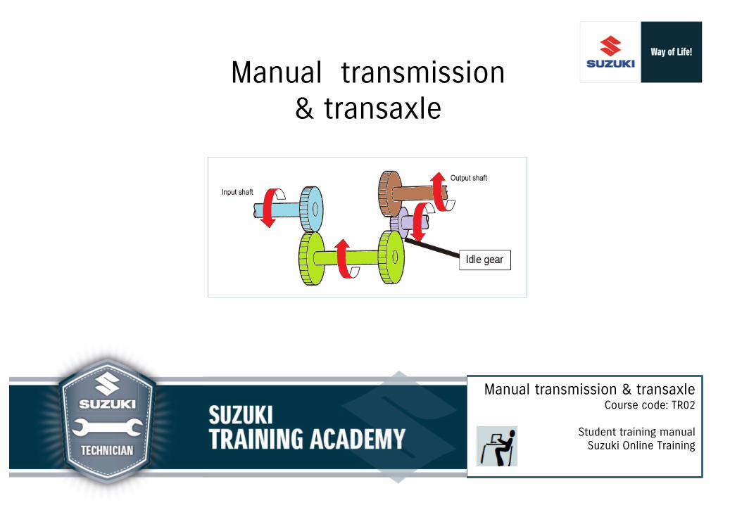
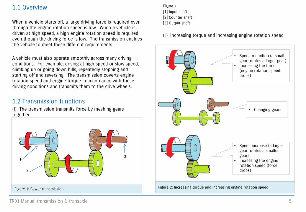
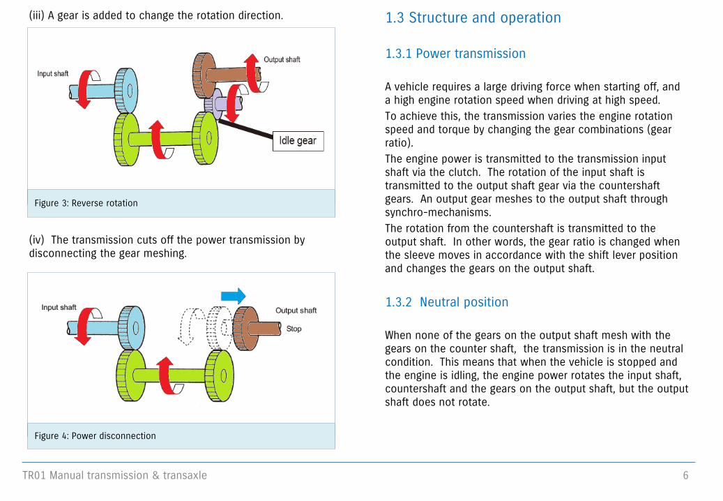
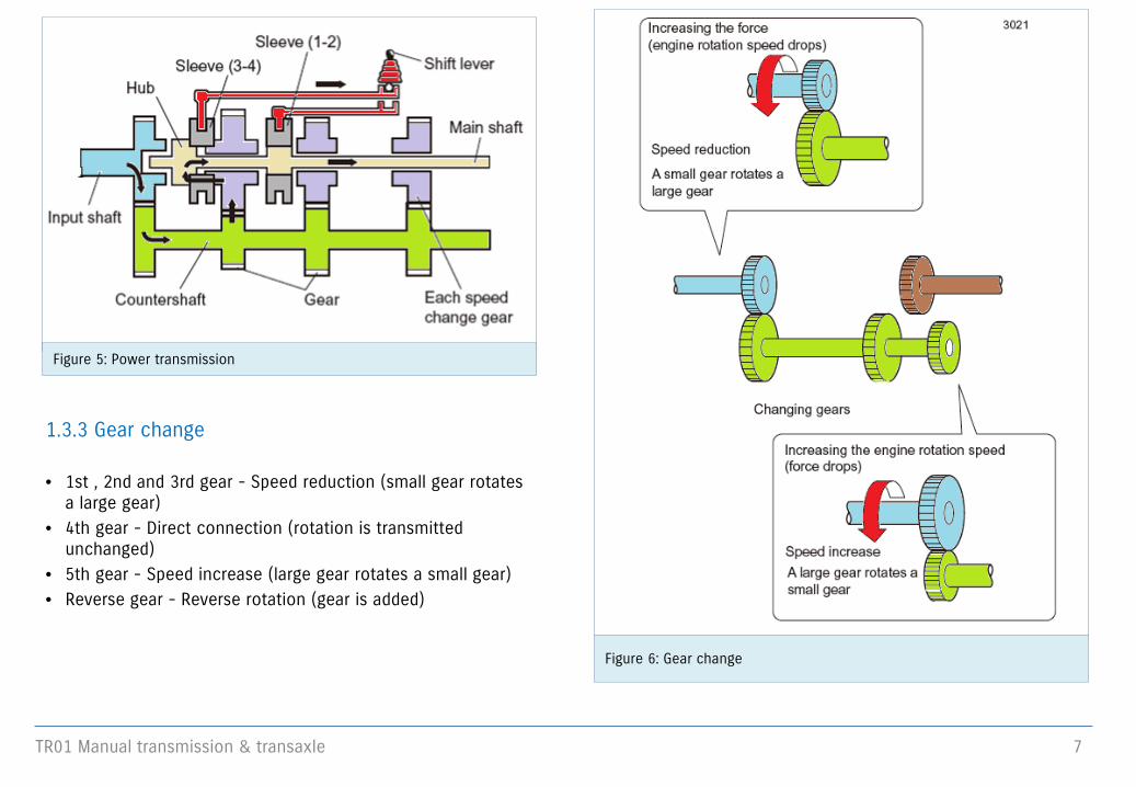
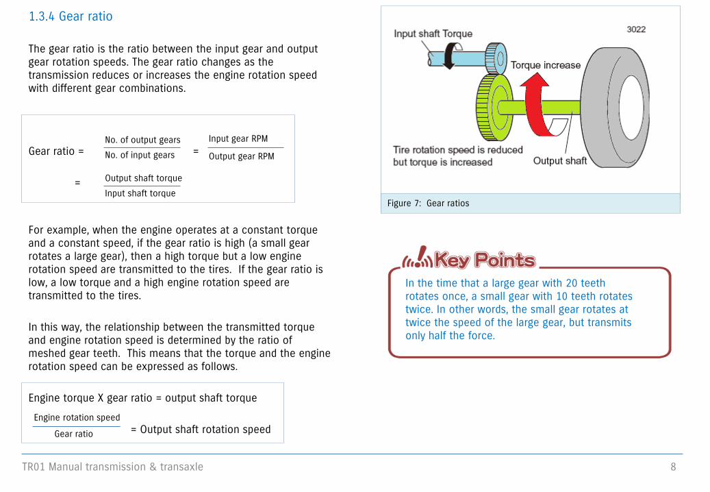
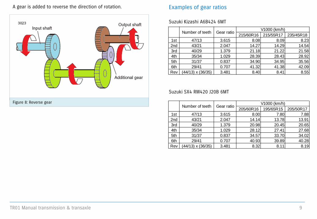
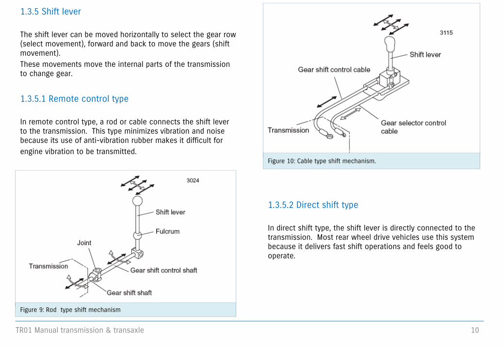
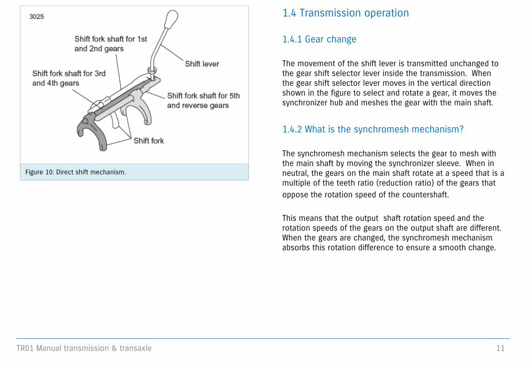
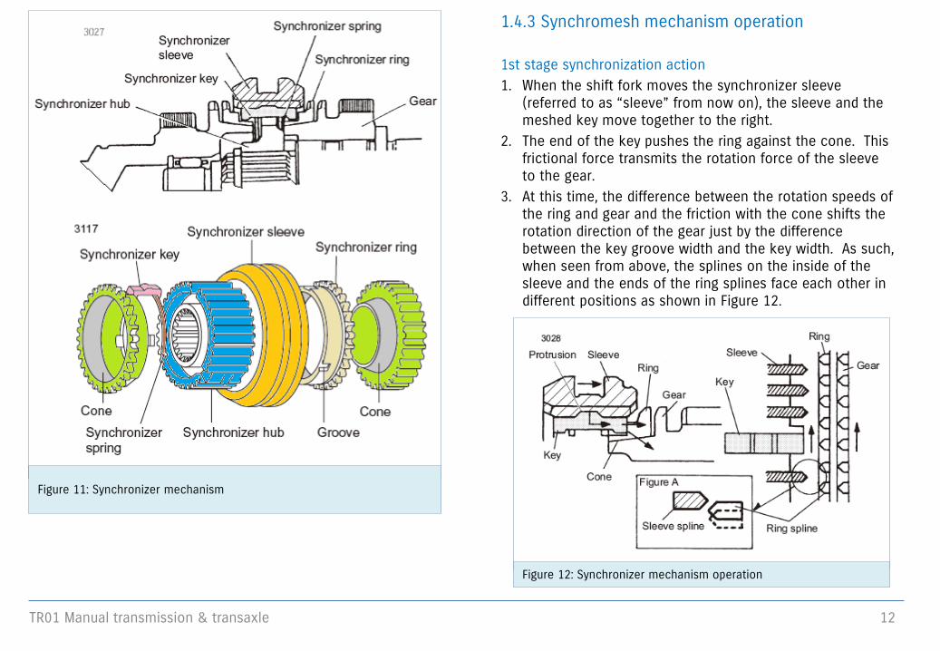
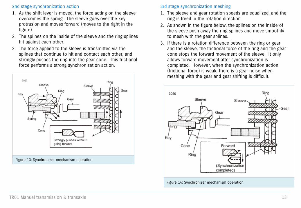
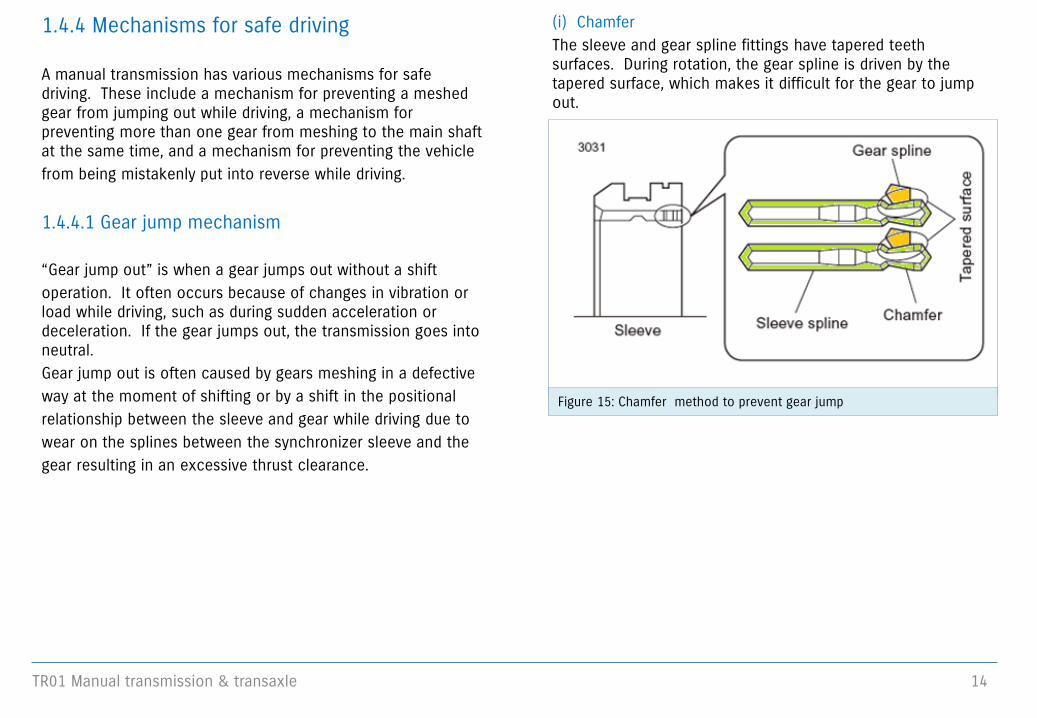
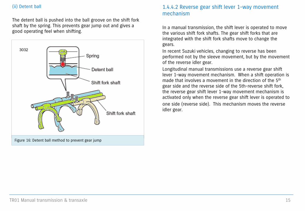
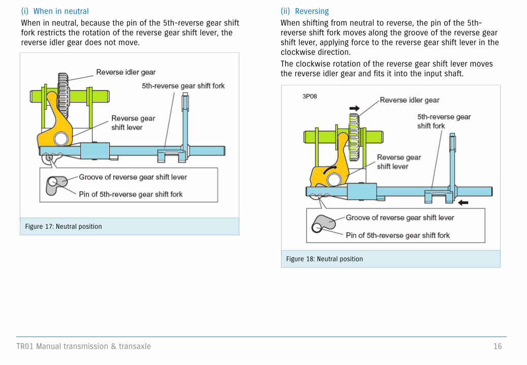
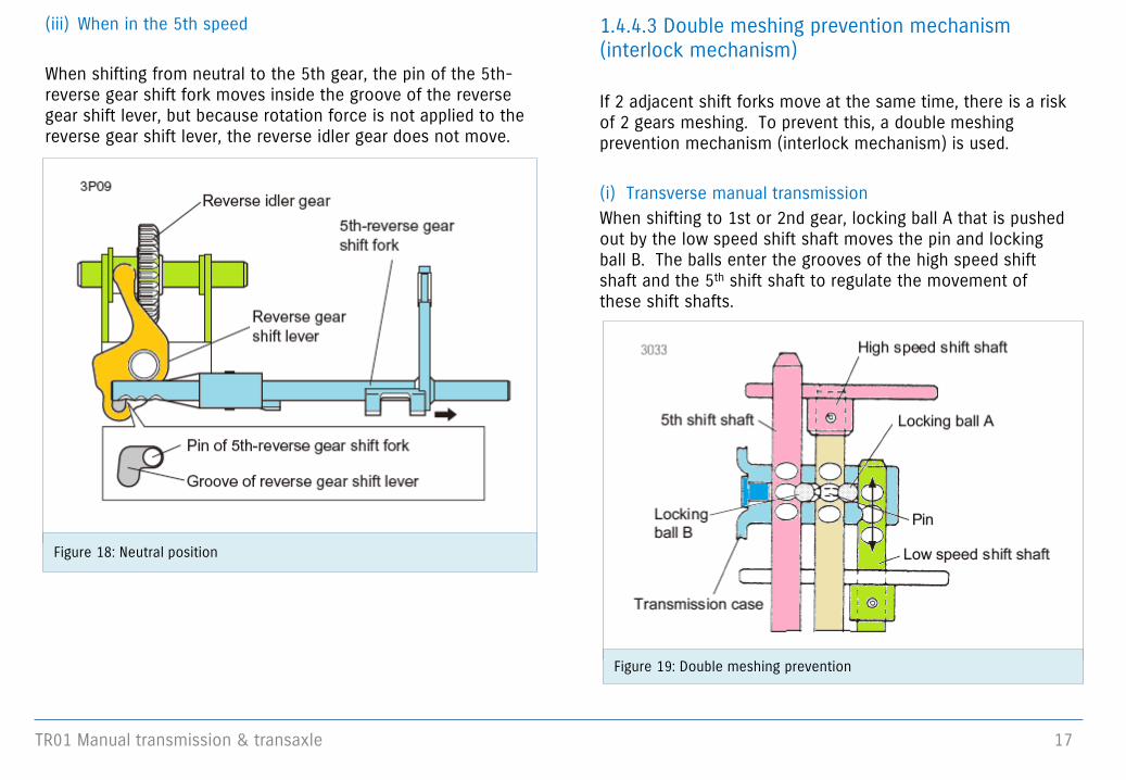
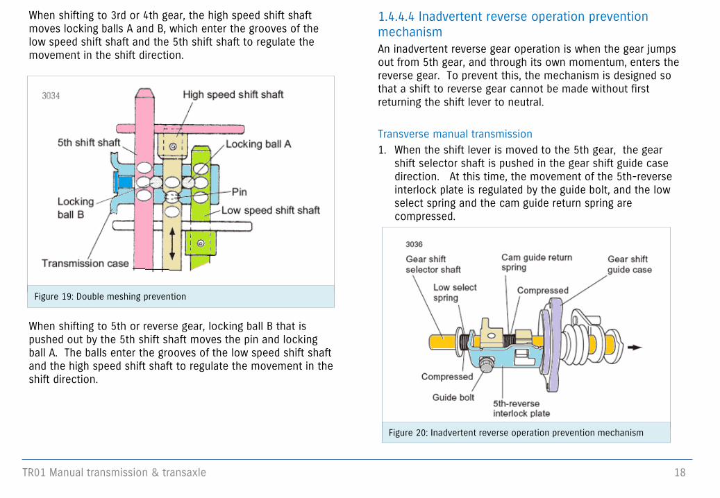
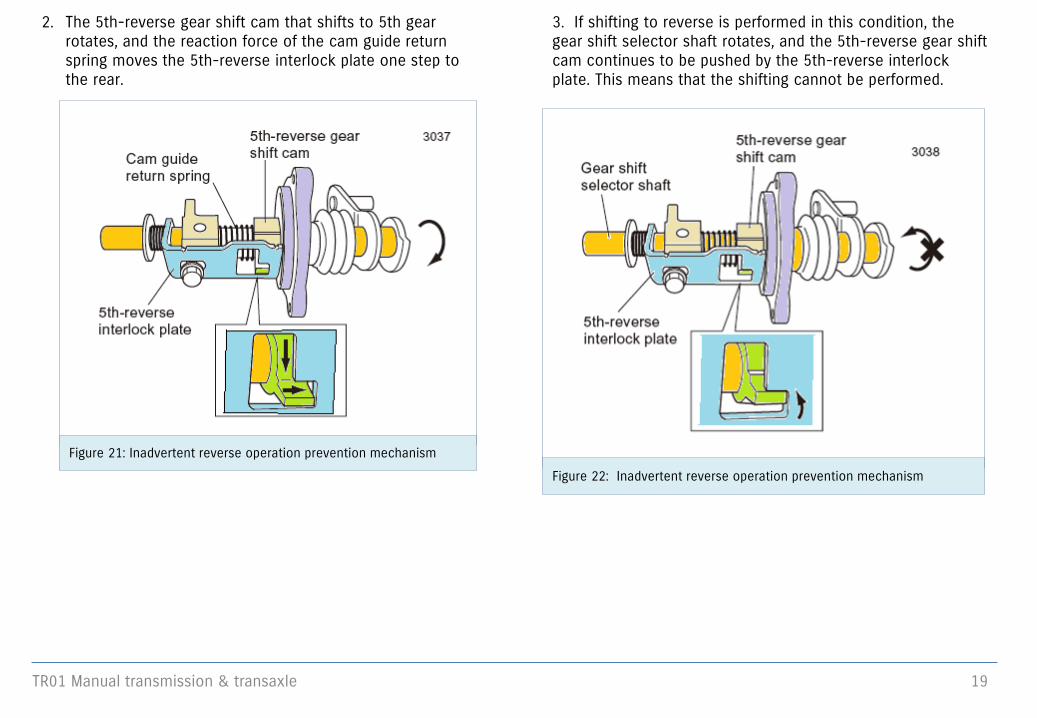
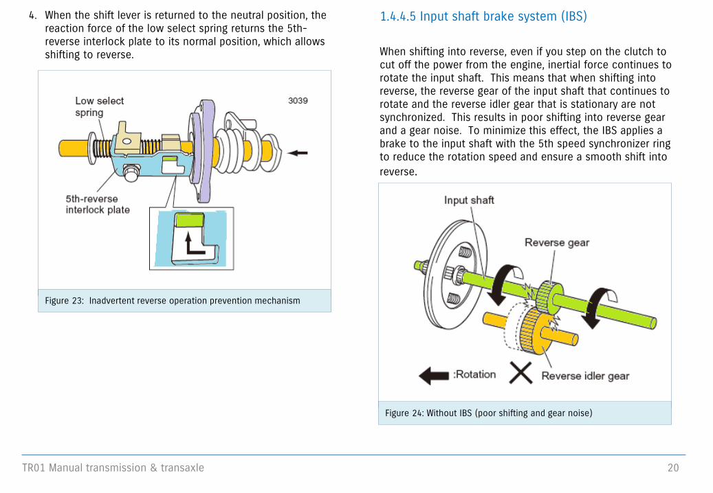
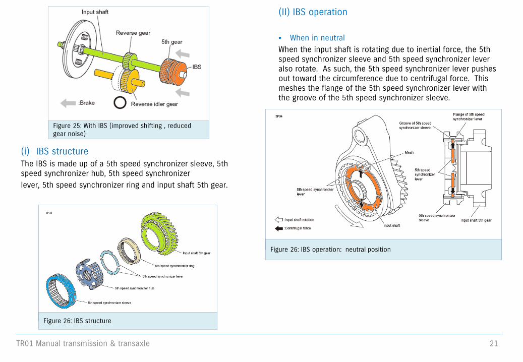
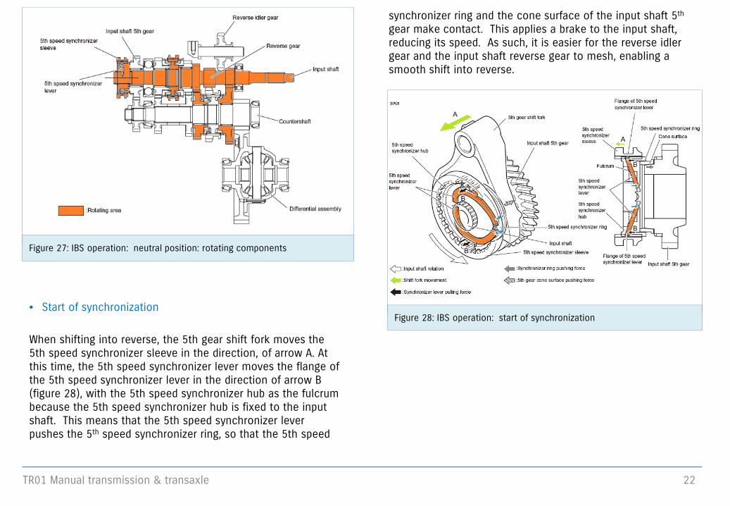
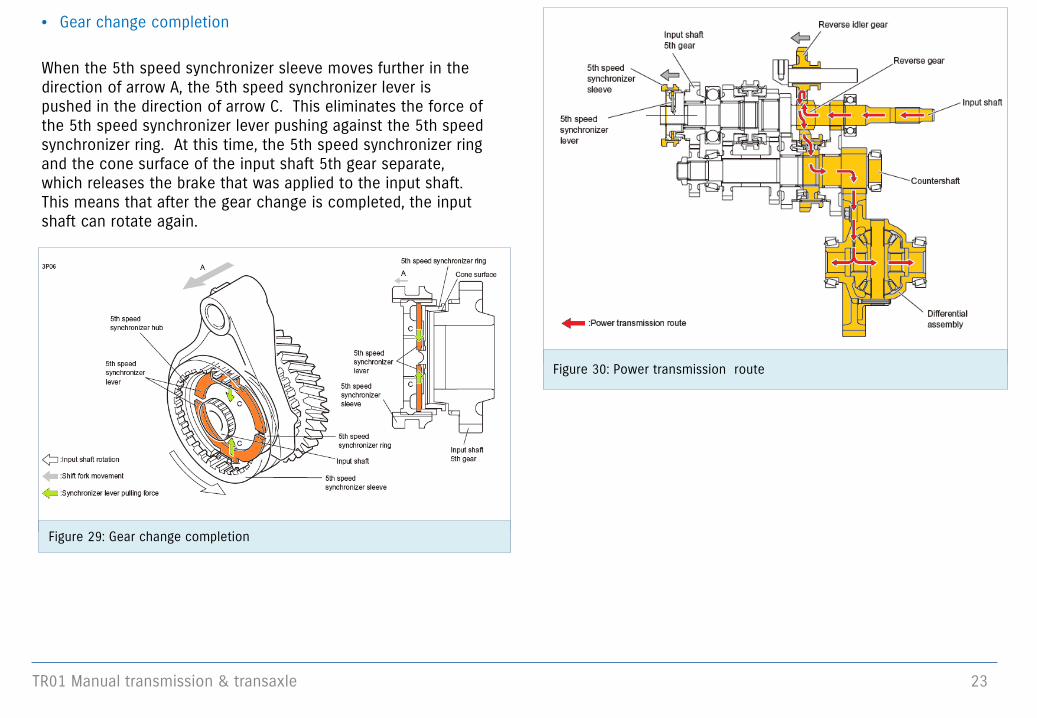
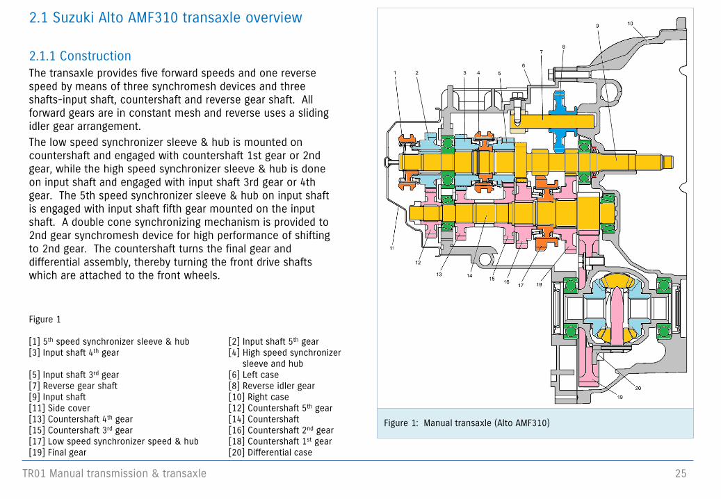
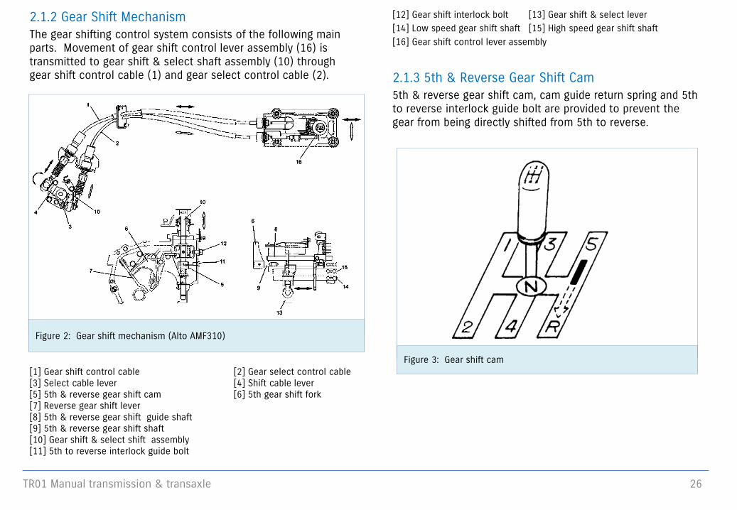
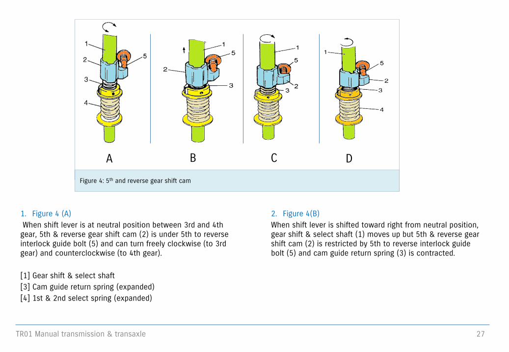
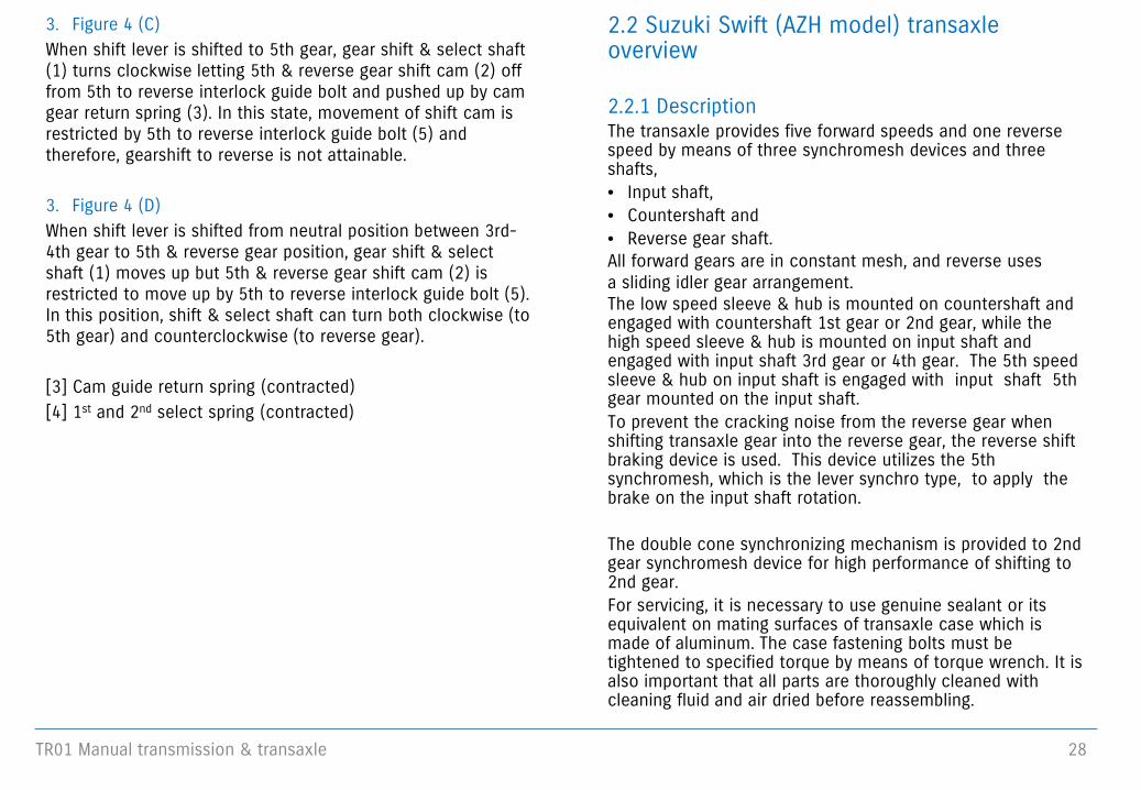
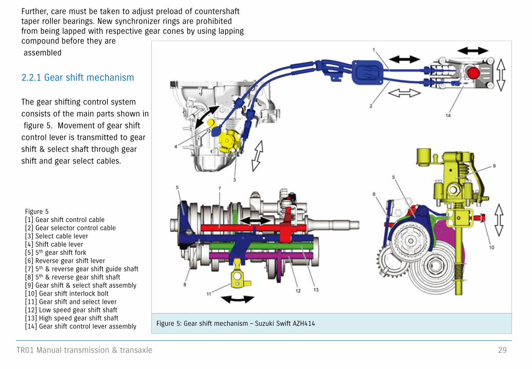
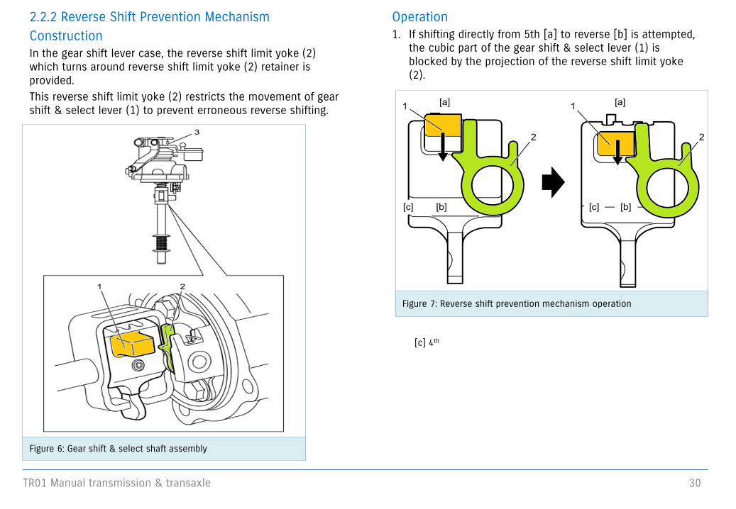

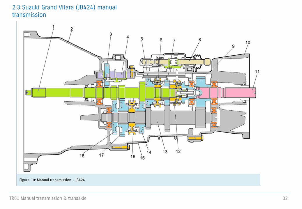
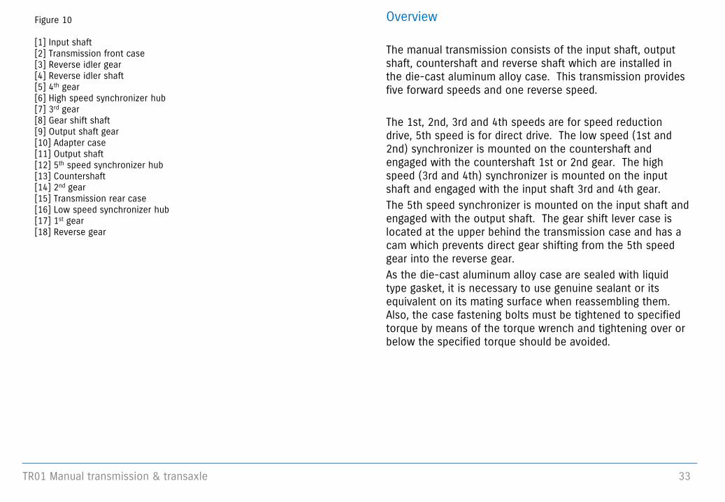
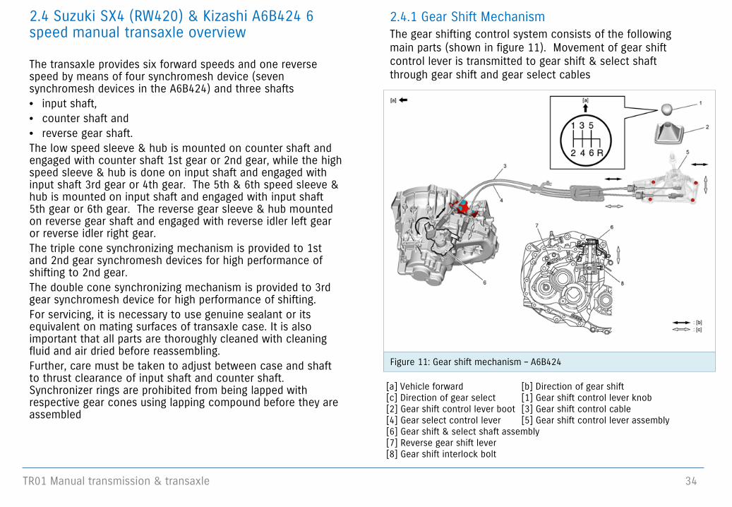
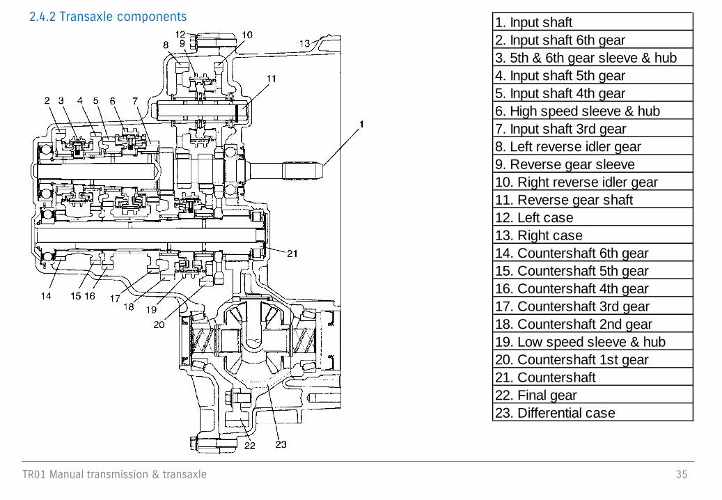
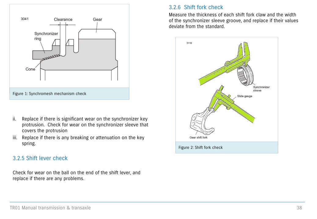
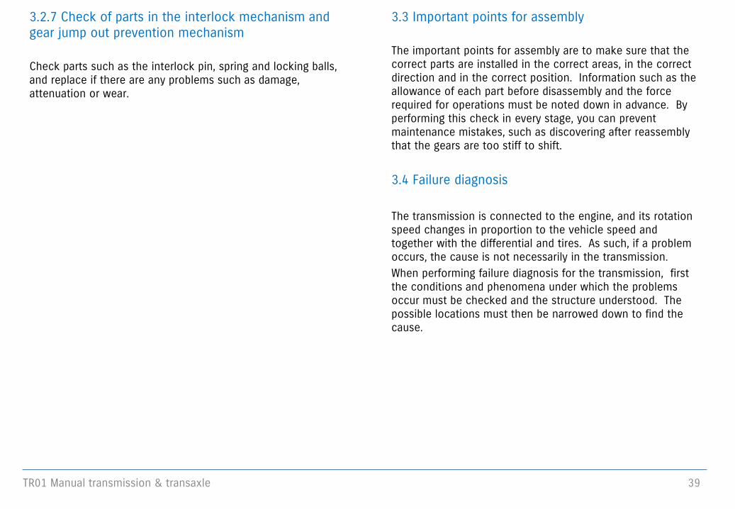
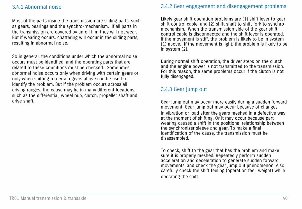
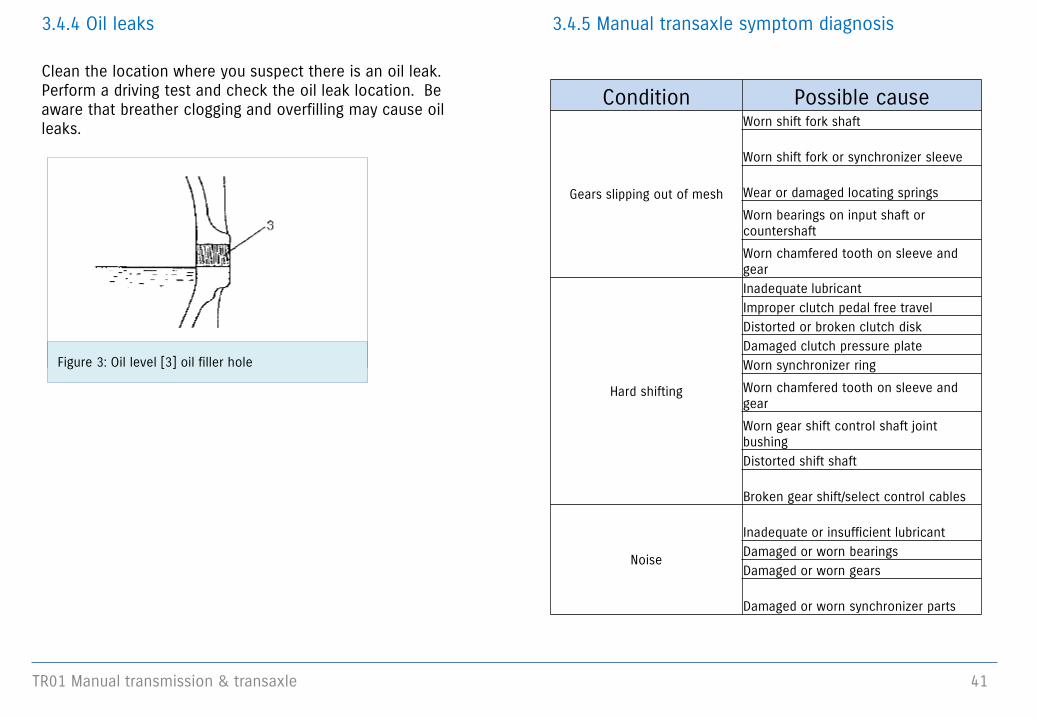
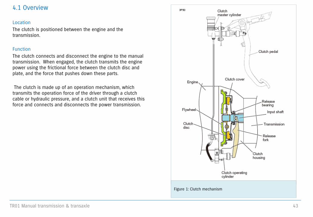
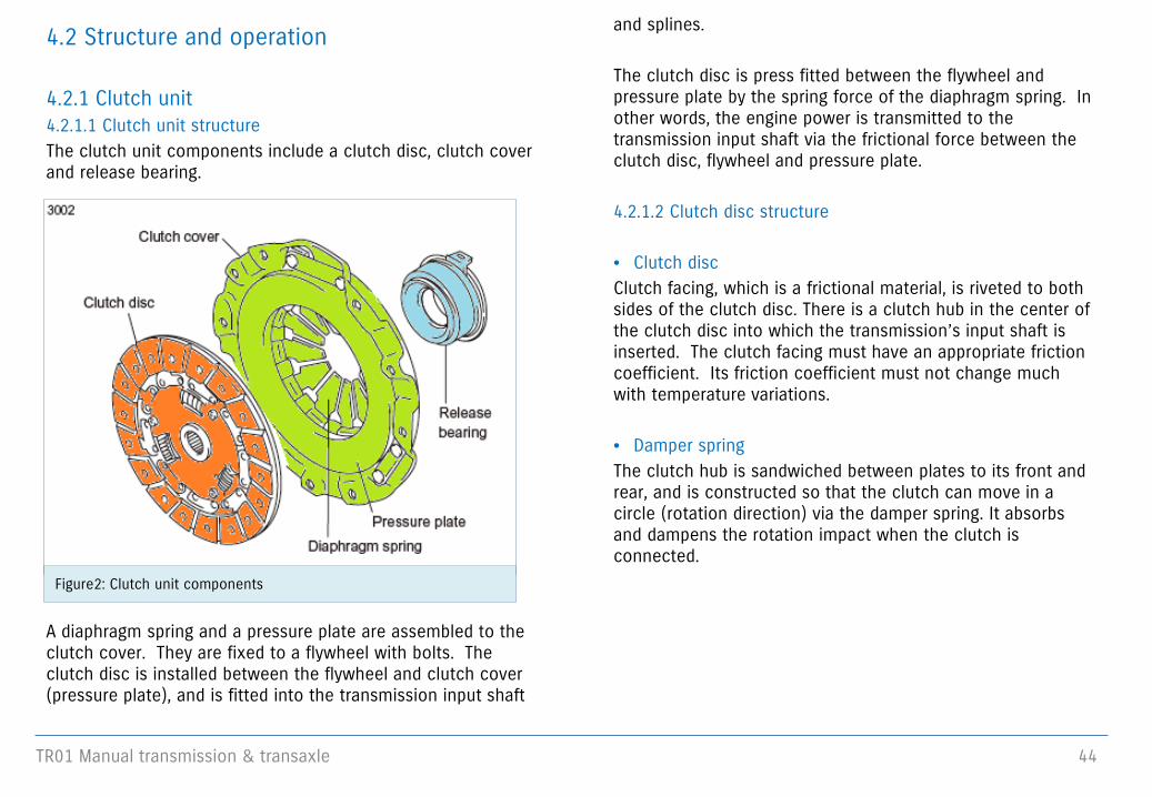
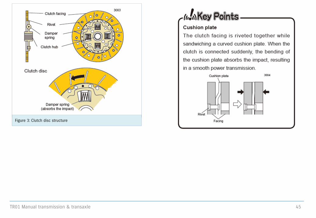
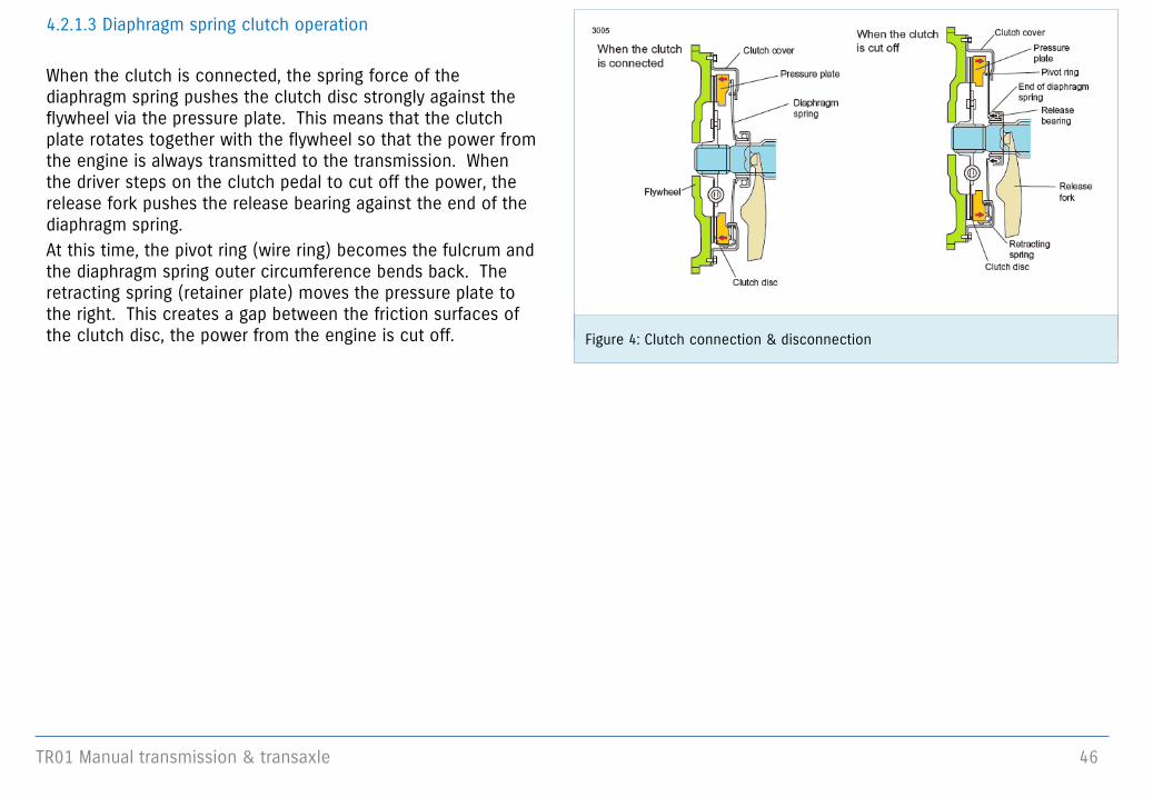
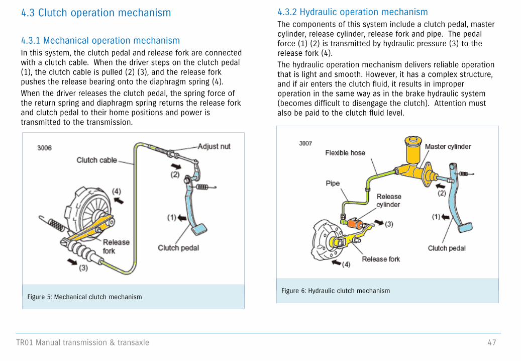
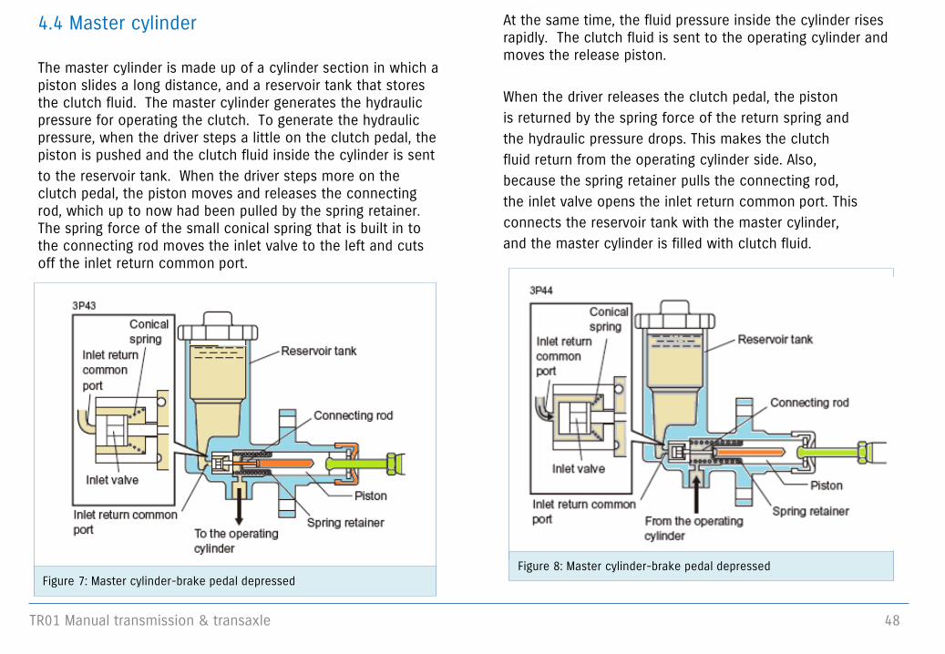
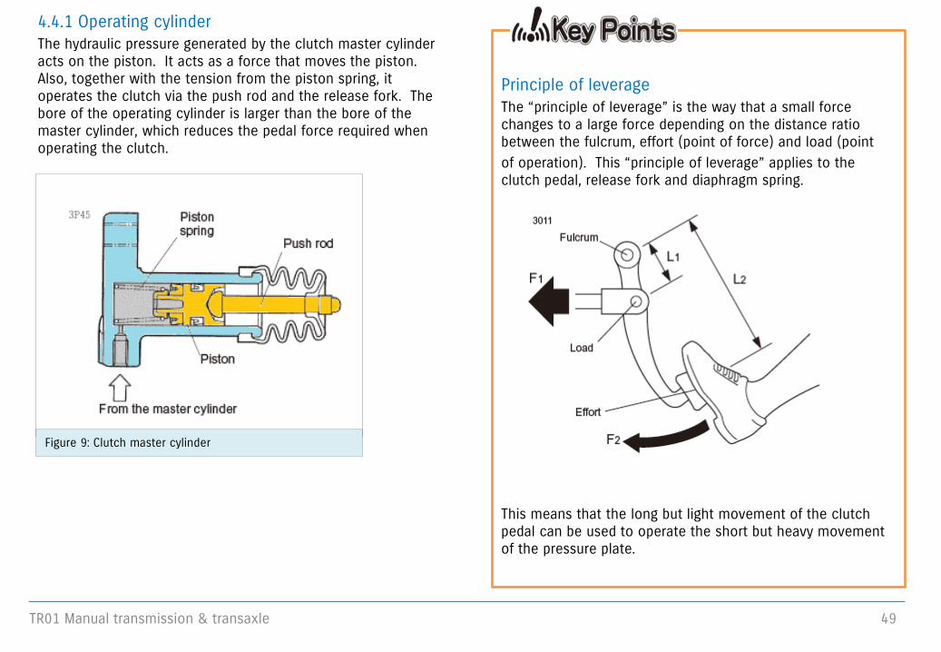
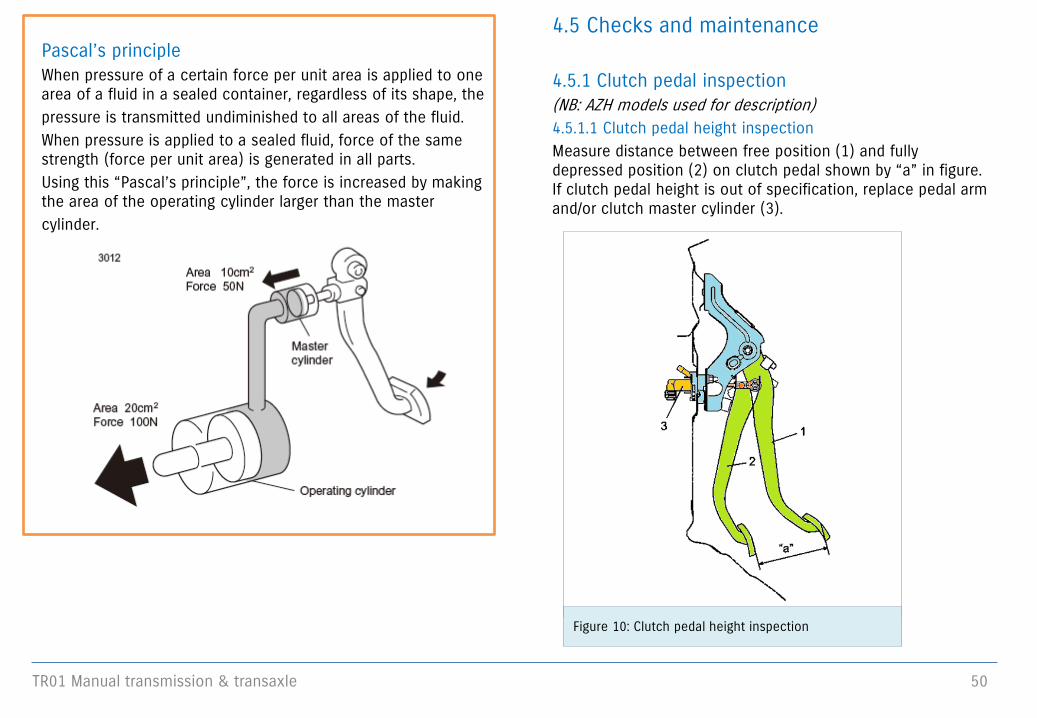
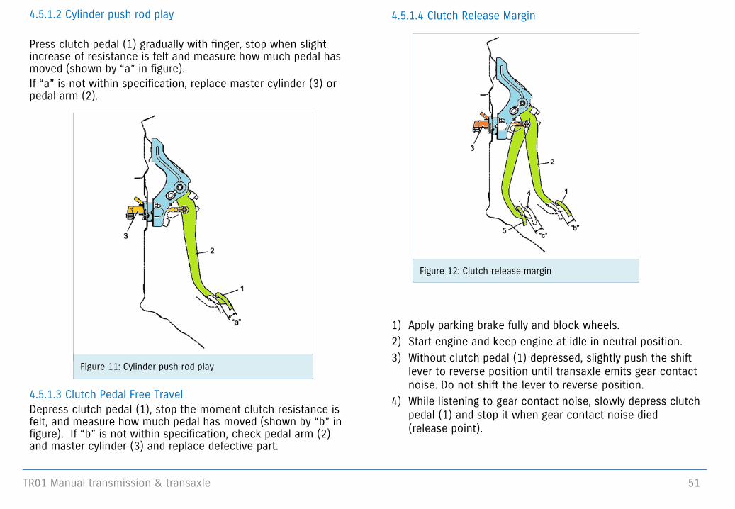
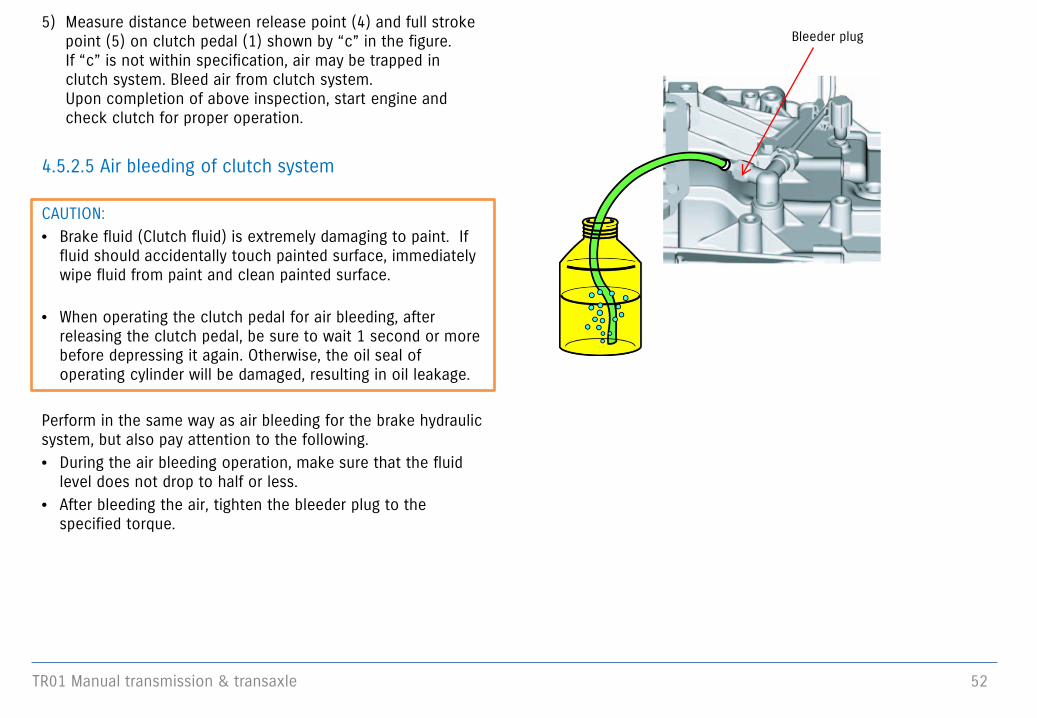
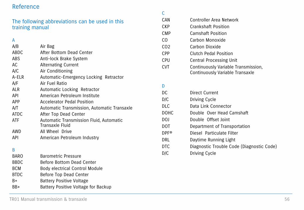
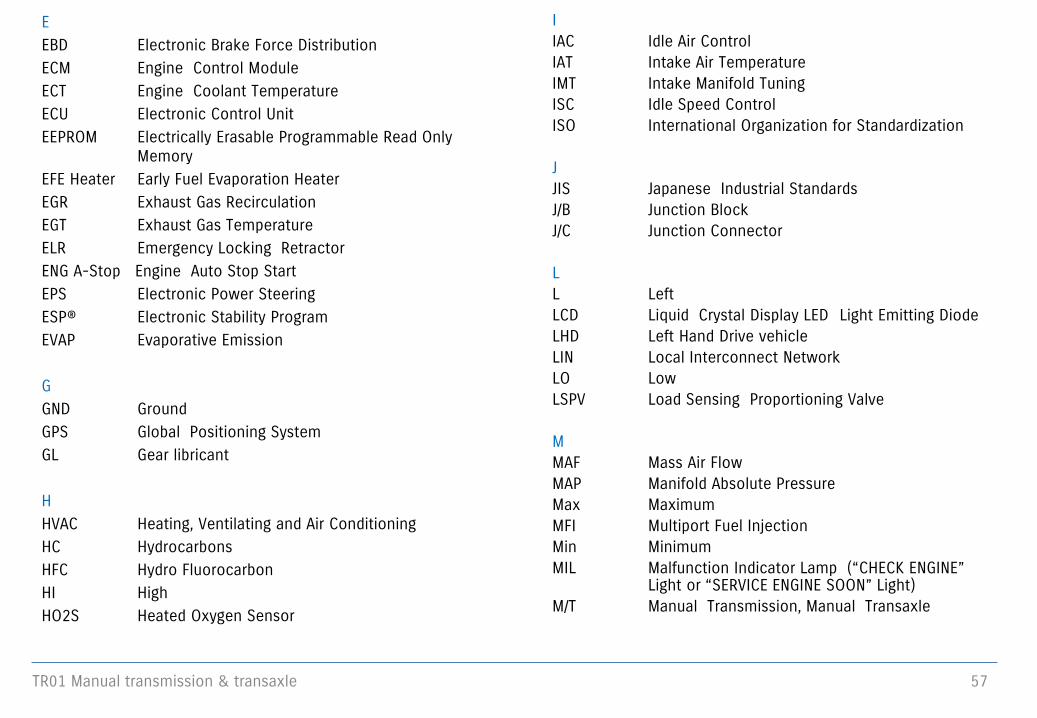


![U660E AUTOMATIC TRANSMISSION / TRANSAXLE: … · u660e automatic transmission / transaxle: automatic transaxle fluid: adjustment; 2013 my camry [12/2012 -] 1. precautions and work](https://img.pdfslide.us/doc/110x75/5adfe3927f8b9ac0428cc9f3/u660e-automatic-transmission-transaxle-automatic-transmission-transaxle.jpg)