Embed Size (px)
Citation preview

OPERATION AND MAINTENANCE
MODELS TU-2, TU-3, TU-5, TU-7, TU-11, TU-20, TU-27 & TU-60
MANUALTU Series Square Drive Hydraulic Torque Wrenches
TU Series
Phone: +1 610-250-5800 Fax: +1 610-250-2700
Toll Free: 1-888-TORCUP-1Email: [email protected] Website: www.torcup.com1025 Conroy Place, Easton, PA. 18040 U.S.A.

1
Operational and Maintenance Manual for TorcUP TU-2, TU-3, TU-5, TU-11, TU-20 ,TU-27 AND TU-60
Square Drive Hydraulic Torque WrenchesVersion 2: 2016 September
Series TU-2, TU-3,TU-5, TU-7, TU-11, TU-20, TU-27 and TU-60 Square Drive Hydraulic Torque Wrenches are designed for installing and removing threaded fasteners requiring precise high torque
during bolt makeup and maximum torque during bolt breakout.
TorcUPInc.isnotresponsibleforcustomermodificationoftoolsforapplicationson which TorcUP Inc. was not consulted.
IMPORTANT SAFETY INFORMATION ENCLOSED.READ THIS MANUAL BEFORE OPERATING TOOL.
IT IS THE RESPONSIBILITY OF THE EMPLOYER TO PLACE THE INFORMATION IN THIS MANUAL INTO THE HANDS OF THE OPERATOR.
FAILURE TO OBSERVE THE FOLLOWING WARNINGS COULD RESULT IN INJURY.
USING THE TOOL
• Always operate, inspect and maintain this tool in accordance with American National Standards Safety Code for Hydraulic Rams and Jacks (ANSI B30.1).
• This tool will function using an air or electric powered hydraulic pump. Adhere to the pump safety requirements and follow instructions when connecting the pump to the tool.
• Use only equipment rated for the same pressure and torque.• Use only a hydraulic pump capable of generating 10,000 psi (681 bar) maximum pressure with this
tool.• Use only twin line hydraulic hose rated for 10,000 psi (681 bar) pressure with this tool.• Do not interchange the male and female swivel inlets on the tool or the connections on one end of
the hose. Reversing the inlets will reverse the power stroke cycle and may damage the tool.• Donotusedamaged,frayedordeterioratedhosesandfittings.Makecertaintherearenocracks,
splits or leaks in the hoses.• Use the quick connect system to attach the hoses to the tool and pump.• When connecting hoses that have not been preloaded with hydraulic oil, make certain the pump
reservoir is not drained of oil during start-up.• Do not remove any labels. Replace any damaged label.• Do not handle pressurized hoses. Escaping oil under pressure can penetrate the skin, causing
serious injury. If oil is injected under the skin, see a doctor immediately.• Never pressurize uncoupled couplers. Only use hydraulic equipment in a coupled system.• Always wear eye protection when operating or performing maintenance on this tool.• Always wear head and hand protection and protective clothing when operating this tool.
The use of other than genuine TorcUP replacement parts may result in safety hazards, decreased tool performance, increased maintenance, and may invalidate
all warranties. Repairs should be made only by authorized personnel. Consult your nearest TorcUP Authorized Service Center.
Refer All Communications to the Nearest TorcUP Office or Distributor.
NOTICE
WARNING
For Technical Support & Information Contact:TorcUP Inc.
1025 Conroy Place, Easton, PA 18040 USAPhone: +1 610-250-5800 Fax:+1 610-250-2700
email: [email protected]

2
FAILURE TO OBSERVE THE FOLLOWING WARNINGS COULD RESULT IN INJURY
Do NOT Exceed Maximum Pressure. See Torque Chart with Tool. Damage May Occur.
Always wear ear protection when operating this tool.
Do not carry the toolby the hose.
Keep body stance balancedandfirm.Do not overreachwhen operating this tool.
USING THE TOOL
• Keep hands, loose clothing and long hair away from the reaction arm and working area during operation. • This tool will exert a strong reaction force. Use proper mechanical support and correct reaction arm
positioning to control these forces. Do not position the reaction arm so that it tilts the tool off the axis of the bolt and never use the swivel inlets as a reaction stop.
• Avoid sharp bends and kinks that will cause severe back-up pressure in hoses and lead to premature hose failure.
• Use accessories recommended by TorcUP. • Use only impact sockets and accessories. Do not use hand (chrome) sockets or accessories.• Useonlysocketsandaccessoriesthatcorrectlyfittheboltornutandfunctionwithouttiltingthetooloffthe
axis of the bolt.• This tool is not insulated against electric shock. • This equipment must not be operated or serviced unless the operator read the operating instructions and
fully understands the purpose, consequences and procedure of each step.• When operating a larger tool (TU-20, TU-27, or TU-60) above waist height, employ a secondary means of
support for safety purposes. A tool sling or chains may be used. Consult your safety department for further suggestions.
Depending on the working environment your local health and safety regulations may require you wear protective gear (i.e. safety shoes, hard hat, gloves, coveralls, etc.). In case external forces are exerted on the equipment, non-compliance with these regulations may result in injury. EAR PROTECTION MUST BE WORN WHEN OPERATING THIS TOOL.
The Reaction Arm must be positioned against a positive stop. Do not use the arm as a dead handle. Take precautions to make certain the operator’s hand cannot be pinched between the arm and a solid object.
Do not use damaged, frayed or deteriorated hydraulic hoses andfittings.
Always wear eyeprotection when operating orperforming maintenance on this tool.
WARNING
3
PLACING THE TOOL IN SERVICE
CONNECTING THE TOOL
1. Attach the twin line hose to the swivel inlets of the square drive torque wrench using the spring–loaded quick connect ends.
2. Connect the opposite ends of the hose to the pump in the same manner.
ADJUSTMENTS
SETTING THE SQUARE DRIVE FOR ROTATION
The position of the square drive when looking toward the shroud will determine if the tool is set to tighten or loosen the nut. When the square drive extends to the left (when looking at the shroud with the inlets away from you), the tool is set to loosen the nut. When the square drive extends to the right, the tool is set to tighten the nut. To change the direction of rotation for models TU-2 TU-3, TU-7 and TU-11 simply push the square drive into the housing until the drive projects out the opposite side of the tool. For models TU-5, TU-20, TU-27 and TU-60, loosen and remove the square drive retaining knob and pull the square drive out of the housing. Insert the square drive into the opposite side of the housing and secure it by install-ing the knob in the splined end of the drive.
SETTING THE TORQUE
Afterdeterminingthedesiredtorque,usethecalibrationcertificateprovidedwiththetooltodetermine the pressure necessary to achieve that torque. You may also refer to the chart en-graved on the shroud of the tool or the charts provided on pages 9-16 of this manual.
1. Connect the tool to the power supply and turn the pump on.
2. Depress the remote control button causing the pressure to be shown on the gauge.
3. Adjust the pressure by loosening the wing nut that locks the pressure adjustment thumb screw. Rotate the thumbscrew clockwise to increase the pressure and counterclockwise to decrease the pressure. When decreasing pressure, always lower the pressure below the desired point and then bring the gauge back up to the desired pressure.
4. When the desired pressure is reached, retighten the wing nut and cycle the tool again to confirmthatthedesiredpressuresettinghasbeenobtained.
4
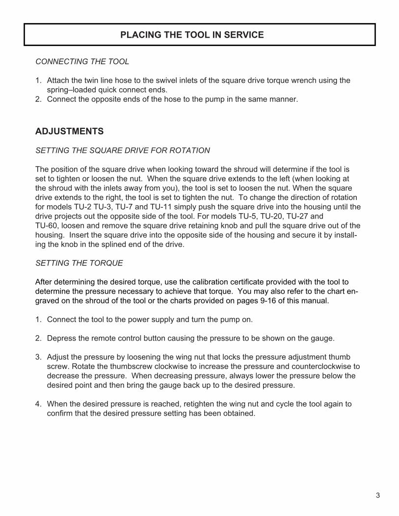
The function of a reaction device is to hold the tool in position against the forces generated to tighten or loosen bolts or nuts. Hydraulic wrenches generate tremendous force.
SETTING THE REACTION ARM
An improperly positioned reactionarm may result in operator injuryor damage to tooling.
REACTIONCONTACT
POINTS
REACTIONCONTACT
POINTS
REACTIONCONTACT
POINTS
REACTIONCONTACT
POINTS
Square Drive Hydraulic Wrench Reaction Points (Dwg.01)
Make sure the reaction arm is positioned correctly. (Refer to Dwg. 01).
The reaction arm can be positioned numerous places within a 360O circle. However, for the arm to be correctly positioned, it must be set within a 90O quadrant of that circle. That quadrant is the area located between the protruding square drive and at the bottom of the housing away from the swivel inlets. It will always be toward the lower half of the housing and on one side of the housing when tightening and on the other side when loosening.(Dwg. 01)
5
OPERATING THE WRENCH
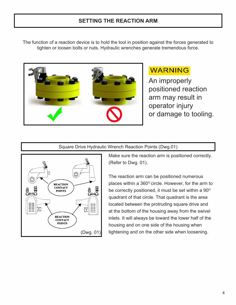
The position of the square drive relative to the shroud determines whether the action will tighten or loosen thenut. (Refer to Dwg. 02 for application examples).The power stroke of the piston assembly will always turn the square drive toward the shroud.
1. Insert the square drive into the mating socket. Then, insert the safety pin through the socket and seat the included O-ring into the groove to capture the pin. Place the socket onto the nut making sure the socket is the proper size and that all mating parts are fully seated.
2. Position the reaction arm or surface against an adjacentnut,flangeorsolidsystemcomponent.Make certain that there is clearance for the hoses, swivels, inlets and end plug. DO NOT allow the tool to react against the hoses, swivels, inlets or end plug.
3. After turning the pump on and presetting the pressure for the correct torque, depress the remote control button to advance the piston assembly.
4. Once the wrench is started, the reaction surface of the wrench or reaction arm will move against the contact point and the nut will begin to turn.
5. When the nut is no longer turning and the pump gauge reaches the preset pressure, release the remote control button. The piston rod will retract when the button is released. Under normal conditions, an audible “click” will be heard as the tool resets itself.
6. Continue to cycle the tool until it “stalls” and the preset psi/torque has been attained.
7. Cycle the tool one additional time to ensure full torque.
Square Drive Position for Loosening and Tightening (Dwg.02)
(Dwg. 02)
6
MARINE MOLY GREASE
Lubrication frequency is dependent on factors known only to the user. The amount of contaminants in the work area is one factor. Tools used in a clean room environment will obviously require less service than a tool used outdoors and dropped in loose dirt or sand. Marine Moly Grease is formulated not to wash out of the tool in areas where lubrication is critical.
Whenever lubrication is required, lubricate as follows:
1. Remove the drive plate, ratchet, drive segment and sleeves as instructed in the maintenance section and wash the components in a suitable cleaning solution in a well ventilated area.
2. Afterdryingthecomponents,wipeafilmofMarineMolyGreaseontothewearsurfaceofboth sleeves and the ends of the ratchet.
3. SpreadalightfilmofMarineMolyGreaseontotheinnerfaceandbothsidesofthedriveplate. Do not pack the teeth of the drive segment or ratchet with lubricant. It can prevent the teeth from engaging properly.
4. Place a daub of Marine Moly Grease in the piston rod recess of the drive plate before linking the piston rod to the drive plate at assembly.
CRITICAL LUBRICATION
It is imperative to lubricate the piston rod recess of the drive plate to piston rod contact area every 80 hours of continuous duty cycling.
Lubricate as follows:
1. Remove shroud screws, shroud, and roll pin.
2. Pry the drive plate assembly forward from the piston rod to expose the recessed contact area in the drive plate.
3. With a rag, wipe clean the area and apply a sizeable amount of Marine Moly Grease.
4. Reassemble as instructed in the maintenance section.
LUBRICATION
7
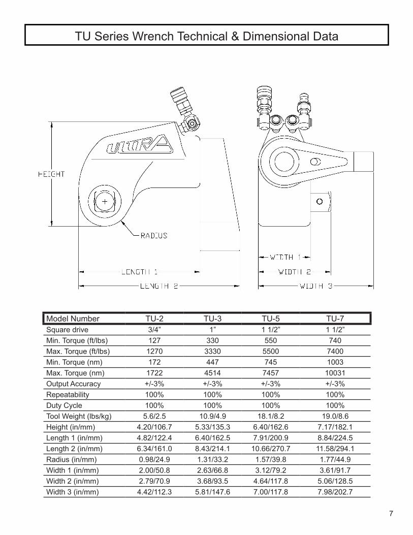
TU Series Wrench Technical & Dimensional Data
Model Number TU-2 TU-3 TU-5 TU-7Square drive 3/4” 1” 1 1/2” 1 1/2”Min. Torque (ft/lbs) 127 330 550 740Max. Torque (ft/lbs) 1270 3330 5500 7400Min. Torque (nm) 172 447 745 1003Max. Torque (nm) 1722 4514 7457 10031Output Accuracy +/-3% +/-3% +/-3% +/-3%Repeatability 100% 100% 100% 100%Duty Cycle 100% 100% 100% 100%Tool Weight (lbs/kg) 5.6/2.5 10.9/4.9 18.1/8.2 19.0/8.6Height (in/mm) 4.20/106.7 5.33/135.3 6.40/162.6 7.17/182.1Length 1 (in/mm) 4.82/122.4 6.40/162.5 7.91/200.9 8.84/224.5Length 2 (in/mm) 6.34/161.0 8.43/214.1 10.66/270.7 11.58/294.1Radius (in/mm) 0.98/24.9 1.31/33.2 1.57/39.8 1.77/44.9Width 1 (in/mm) 2.00/50.8 2.63/66.8 3.12/79.2 3.61/91.7Width 2 (in/mm) 2.79/70.9 3.68/93.5 4.64/117.8 5.06/128.5Width 3 (in/mm) 4.42/112.3 5.81/147.6 7.00/117.8 7.98/202.7

8
TU Series Wrench Technical & Dimensional Data
Model Number TU-11 TU-20 TU-27 TU-60Square drive 1 1/2” 2 1/2” 2 1/2” 2 1/2”Min. Torque (ft/lbs) 1100 1940 2720 5800Max. Torque (ft/lbs) 11010 20625 27200 58000Min. Torque (nm) 1491 2630 3687 7862Max. Torque (nm) 14925 27964 36872 78625Output Accuracy +/-3% +/-3% +/-3% +/-3%Repeatability 100% 100% 100% 100%Duty Cycle 100% 100% 100% 100%Tool Weight (lbs/kg) 29.0/13.1 61.0/27.6 70.0/31.7 130.0/59.8Height (in/mm) 7.80/198.1 9.22/234.3 10.19/258.8 11.50/292.1Length 1 (in/mm) 9.79/248.6 9.44/239.7 12.32/312.9 15.38/390.7Length 2 (in/mm) 12.79/324.8 16.09/408.9 16.33/414.8 20.40/518.2Radius (in/mm) 2.03/51.5 2.31/58.7 2.46/62.5 3.10/78.7Width 1 (in/mm) 3.95/100.3 4.87/123.6 5.26/133.6 6.58/167.1Width 2 (in/mm) 5.43/137.9 7.15/181.7 7.57/192.3 8.89/225.8Width 3 (in/mm) 8.72/221.5 10.88/276.4 11.63/295.4 14.29/363.0
9
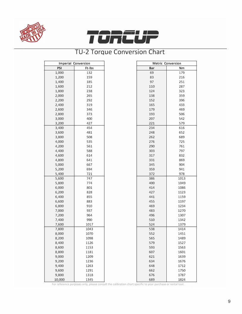
-�----··-1un�ur TU-2 Torque Conversion Chart
Imperial Conversion Metric Conversion PSI
1,000 1,200 1,400 1,600 1,800 2,000 2,200 2,400 2,600 2,800 3,000 3,200 3,400 3,600 3,800 4,000 4,200 4,400 4,600 4,800 5,000 5,200 5,400 5,600 5,800 6,000 6,200 6,400 6,600 6,800 7,000 7,200 7,400 7,600 7,800 8,000 8,200 8,400 8,600 8,800 9,000 9,200 9,400 9,600 9,800 10,000
Ft-lbs 132 159 185 212 238 265 292 319 346 373 400 427 454 481 508 535 561 588 614 641 667 694 721 747 774 801 828 855 883 910 937 964 990
1017 1043 1070 1098 1126 1153 1181 1209 1236 1263 1291 1318 1345
TorcUP, Inc. 1025 Conroy Place Easton, Pa 18040
Bar 69 83 97
110 124 138 152 165 179 193 207 221 234 248 262 276 290 303 317 331 345 359 372 386 400 414 427 441 455 469 483 496 510 524 538 552 565 579 593 607 621 634 648 662 676 689
Tel:610-250-5800 Fax: 610-250-2700
Nm 179 216 251 287 323 359 396 433 469 506 542 579 616 652 689 725 761 797 832 869 904 941 978
1013 1049 1086 1123 1159 1197 1234 1270 1307 1342 1379 1414 1451 1489 1527 1563 1601 1639 1676 1712 1750 1787 1824
AC C R E DITE D
Vi@!◄tit+ CALIBRATION LABORATORY
For reference purposes only, please consult the calibration chart specific to your purchase or rental tool.

10
-�-.... ··-IUn�ur TU-3 Torque Conversion Chart
Imperial Conversion Metric Conversion PSI
1,000 1,200 1,400 1,600 1,800 2,000 2,200 2,400 2,600 2,800 3,000 3,200 3,400 3,600 3,800 4,000 4,200 4,400 4,600 4,800 5,000 5,200 5,400 5,600 5,800 6,000 6,200 6,400 6,600 6,800 7,000 7,200 7,400 7,600 7,800 8,000 8,200 8,400 8,600 8,800 9,000 9,200 9,400 9,600 9,800 10,000
Ft-lbs 347 414 481 547 614 681 748 816 883 951
1018 1085 1152 1220 1287 1354 1421 1487 1554 1620 1687 1754 1822 1889 1957 2024 2092 2160 2229 2297 2365 2432 2499 2565 2632 2699 2769 2838 2908 2977 3047 3115 3183 3251 3319 3387
TorcUP, Inc. 1025 Conroy Place Easton, Pa 18040
Bar 69 83 97
110 124 138 152 165 179 193 207 221 234 248 262 276 290 303 317 331 345 359 372 386 400 414 427 441 455 469 483 496 510 524 538 552 565 579 593 607 621 634 648 662 676 689
Tel:610-250-5800 Fax: 610-250-2700
Nm 470 561 652 742 833 923
1015 1106 1197 1289 1380 1471 1562 1654 1745 1836 1926 2016 2107 2197 2287 2379 2470 2561 2653 2744 2837 2929 3022 3114 3207 3297 3388 3478 3569 3659 3754 3848 3942 4037 4131 4223 4316 4408 4500 4592
ACC R E DITE D
CALIBRATION LABORATORY
For reference purposes only, please consult the calibration chart specific to your purchase or rental tool.

11
_ ... _..., __ _ ,un�ur TU-5 Torque Conversion Chart
Imperial Conversion Metric Conversion PSI
1,000 1,200 1,400 1,600 1,800 2,000 2,200 2,400 2,600 2,800 3,000 3,200 3,400 3,600 3,800 4,000 4,200 4,400 4,600 4,800 5,000 5,200 5,400 5,600 5,800 6,000 6,200 6,400 6,600 6,800 7,000 7,200 7,400 7,600 7,800 8,000 8,200 8,400 8,600 8,800 9,000 9,200 9,400 9,600 9,800 10,000
Ft-lbs 587 705 823 940
1058 1176 1294 1413 1531 1650 1768 1885 2002 2120 2237 2354 2474 2595 2715 2836 2956 3076 3196 3315 3435 3555 3673 3791 3909 4027 4145 4265 4386 4506 4627 4747 4864 4982 5099 5217 5334 5452 5569 5687 5804 5922
TorcUP, Inc. 1025 Conroy Place Easton, Pa 18040
Bar 69 83 97
110 124 138 152 165 179 193 207 221 234 248 262 276 290 303 317 331 345 359 372 386 400 414 427 441 455 469 483 496 510 524 538 552 565 579 593 607 621 634 648 662 676 689
Tel:610-250-5800 Fax: 610-250-2700
Nm 796 956
1116 1274 1434 1594 1754 1916 2076 2237 2397 2556 2714 2874 3033 3192 3354 3518 3681 3845 4008 4170 4333 4495 4657 4820 4980 5140 5300 5460 5620 5783 5947 6109 6273 6436 6595 6755 6913 7073 7232 7392 7551 7711 7869 8029
ACCRE DITE D §/@if,'@
CALIBRATION L.A.BORATORY
For reference purposes only, please consult the calibration chart specific to your purchase or rental tool.
2015 - March
12
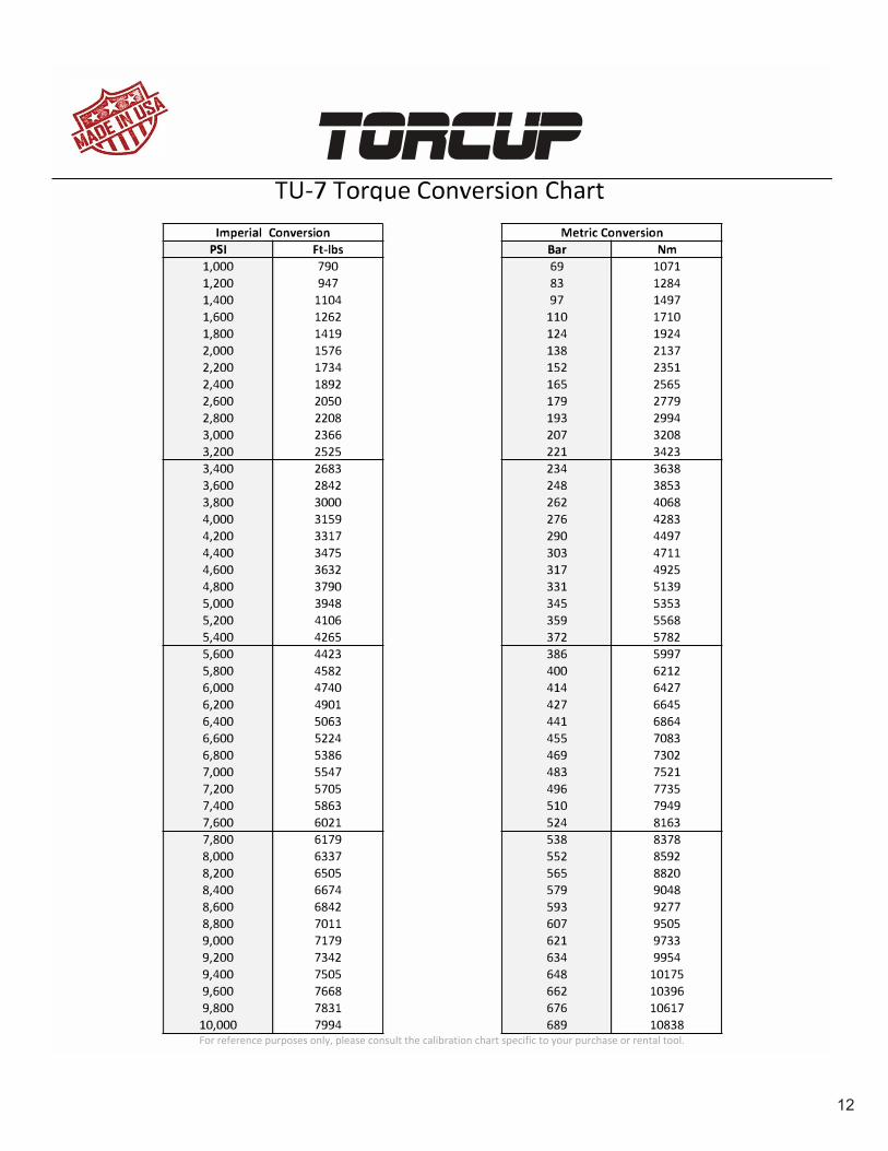
-�-.... ··-IUn�ur TU-7 Torque Conversion Chart
Imperial Conversion Metric Conversion PSI
1,000 1,200 1,400 1,600 1,800 2,000 2,200 2,400 2,600 2,800 3,000 3,200 3,400 3,600 3,800 4,000 4,200 4,400 4,600 4,800 5,000 5,200 5,400 5,600 5,800 6,000 6,200 6,400 6,600 6,800 7,000 7,200 7,400 7,600 7,800 8,000 8,200 8,400 8,600 8,800 9,000 9,200 9,400 9,600 9,800 10,000
Ft-lbs 790 947
1104 1262 1419 1576 1734 1892 2050 2208 2366 2525 2683 2842 3000 3159 3317 3475 3632 3790 3948 4106 4265 4423 4582 4740 4901 5063 5224 5386 5547 5705 5863 6021 6179 6337 6505 6674 6842 7011 7179 7342 7505 7668 7831 7994
TorcUP, Inc. 1025 Conroy Place Easton, Pa 18040
Bar 69 83 97
110 124 138 152 165 179 193 207 221 234 248 262 276 290 303 317 331 345 359 372 386 400 414 427 441 455 469 483 496 510 524 538 552 565 579 593 607 621 634 648 662 676 689
Tel:610-250-5800 Fax: 610-250-2700
Nm 1071 1284 1497 1710 1924 2137 2351 2565 2779 2994 3208 3423 3638 3853 4068 4283 4497 4711 4925 5139 5353 5568 5782 5997 6212 6427 6645 6864 7083 7302 7521 7735 7949 8163 8378 8592 8820 9048 9277 9505 9733 9954
10175 10396 10617 10838
ACC R E DITE D
CALIBRATION LABORATORY
For reference purposes only, please consult the calibration chart specific to your purchase or rental tool.

13
-�-.... ··-IUn�ur TU-11 Torque Conversion Chart
Imperial Conversion Metric Conversion PSI
1,000 1,200 1,400 1,600 1,800 2,000 2,200 2,400 2,600 2,800 3,000 3,200 3,400 3,600 3,800 4,000 4,200 4,400 4,600 4,800 5,000 5,200 5,400 5,600 5,800 6,000 6,200 6,400 6,600 6,800 7,000 7,200 7,400 7,600 7,800 8,000 8,200 8,400 8,600 8,800 9,000 9,200 9,400 9,600 9,800 10,000
Ft-lbs 1198 1433 1668 1904 2139 2374 2612 2850 3088 3326 3564 3802 4041 4279 4518 4756 4990 5225 5459 5694 5928 6164 6400 6635 6871 7107 7348 7589 7831 8072 8313 8547 8781 9015 9249 9483 9727 9971
10214 10458 10702 10943 11184 11426 11667 11908
TorcUP, Inc. 1025 Conroy Place Easton, Pa 18040
Bar 69 83 97
110 124 138 152 165 179 193 207 221 234 248 262 276 290 303 317 331 345 359 372 386 400 414 427 441 455 469 483 496 510 524 538 552 565 579 593 607 621 634 648 662 676 689
Tel:610-250-5800 Fax: 610-250-2700
Nm 1624 1943 2262 2581 2900 3219 3541 3864 4187 4509 4832 5155 5479 5802 6125 6448 6766 7084 7402 7719 8037 8357 8677 8996 9316 9636 9963
10290 10617 10944 11271 11588 11905 12223 12540 12857 13188 13518 13849 14179 14510 14837 15164 15491 15818 16145
ACCR EDITE D
CALIBRATION LABORATORY
For reference purposes only, please consult the calibration chart specific to your purchase or rental tool.
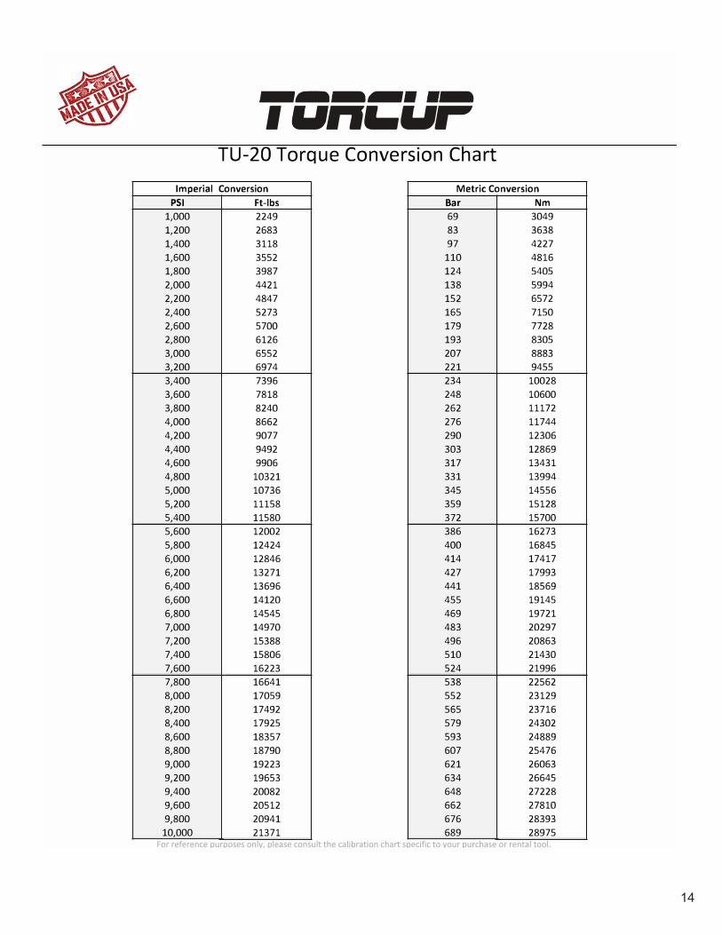
14
-�-.... ··-IUn�ur TU-20 Torque Conversion Chart
Imperial Conversion Metric Conversion PSI
1,000 1,200 1,400 1,600 1,800 2,000 2,200 2,400 2,600 2,800 3,000 3,200 3,400 3,600 3,800 4,000 4,200 4,400 4,600 4,800 5,000 5,200 5,400 5,600 5,800 6,000 6,200 6,400 6,600 6,800 7,000 7,200 7,400 7,600 7,800 8,000 8,200 8,400 8,600 8,800 9,000 9,200 9,400 9,600 9,800 10,000
Ft-lbs 2249 2683 3118 3552 3987 4421 4847 5273 5700 6126 6552 6974 7396 7818 8240 8662 9077 9492 9906
10321 10736 11158 11580 12002 12424 12846 13271 13696 14120 14545 14970 15388 15806 16223 16641 17059 17492 17925 18357 18790 19223 19653 20082 20512 20941 21371
TorcUP, Inc. 1025 Conroy Place Easton, Pa 18040
Bar 69 83 97
110 124 138 152 165 179 193 207 221 234 248 262 276 290 303 317 331 345 359 372 386 400 414 427 441 455 469 483 496 510 524 538 552 565 579 593 607 621 634 648 662 676 689
Tel:610-250-5800 Fax: 610-250-2700
Nm 3049 3638 4227 4816 5405 5994 6572 7150 7728 8305 8883 9455
10028 10600 11172 11744 12306 12869 13431 13994 14556 15128 15700 16273 16845 17417 17993 18569 19145 19721 20297 20863 21430 21996 22562 23129 23716 24302 24889 25476 26063 26645 27228 27810 28393 28975
ACC R E DITE D
CALIBRATION LABORATORY
For reference purposes only, please consult the calibration chart specific to your purchase or rental tool.

15
-�-.... ··-IUn�ur TU-27 Torque Conversion Chart
Imperial Conversion Metric Conversion PSI
1,000 1,200 1,400 1,600 1,800 2,000 2,200 2,400 2,600 2,800 3,000 3,200 3,400 3,600 3,800 4,000 4,200 4,400 4,600 4,800 5,000 5,200 5,400 5,600 5,800 6,000 6,200 6,400 6,600 6,800 7,000 7,200 7,400 7,600 7,800 8,000 8,200 8,400 8,600 8,800 9,000 9,200 9,400 9,600 9,800 10,000
Ft-lbs 3032 3606 4180 4755 5329 5903 6469 7035 7600 8166 8732 9302 9873
10443 11014 11584 12137 12690 13242 13795 14348 14911 15474 16037 16600 17163 17720 18278 18835 19393 19950 20510 21069 21629 22188 22748 23308 23868 24427 24987 25547 26106 26665 27225 27784 28343
TorcUP, Inc. 1025 Conroy Place Easton, Pa 18040
Bar 69 83 97 110 124 138 152 165 179 193 207 221 234 248 262 276 290 303 317 331 345 359 372 386 400 414 427 441 455 469 483 496 510 524 538 552 565 579 593 607 621 634 648 662 676 689
Tel:610-250-5800 Fax: 610-250-2700
Nm 4111 4889 5668 6446 7225 8003 8771 9538
10305 11072 11839 12612 13386 14159 14932 15706 16455 17205 17954 18704 19453 20217 20980 21743 22507 23270 24026 24781 25537 26293 27049 27807 28566 29325 30083 30842 31601 32360 33119 33878 34637 35395 36153 36912 37670 38428
ACC R E DITE D F-i@ifitf
CALIBRATION LABORATORY
For reference purposes only, please consult the calibration chart specific to your purchase or rental tool.

16
-�-.... ··-IUn�ur TU-60 Torque Conversion Chart
Imperial Conversion Metric Conversion PSI
1,000 1,200 1,400 1,600 1,800 2,000 2,200 2,400 2,600 2,800 3,000 3,200 3,400 3,600 3,800 4,000 4,200 4,400 4,600 4,800 5,000 5,200 5,400 5,600 5,800 6,000 6,200 6,400 6,600 6,800 7,000 7,200 7,400 7,600 7,800 8,000 8,200 8,400 8,600 8,800 9,000 9,200 9,400 9,600 9,800 10,000
Ft-lbs 6202 7422 8641 9861
11080 12300 13477 14654 15831 17008 18185 19378 20571 21763 22956 24149 25344 26538 27733 28927 30122 31317 32511 33706 34900 36095 37293 38491 39688 40886 42084 43282 44480 45678 46876 48074 49272 50470 51667 52865 54063 55260 56456 57653 58849 60046
TorcUP, Inc. 1025 Conroy Place Easton, Pa 18040
Bar 69 83 97 110 124 138 152 165 179 193 207 221 234 248 262 276 290 303 317 331 345 359 372 386 400 414 427 441 455 469 483 496 510 524 538 552 565 579 593 607 621 634 648 662 676 689
Tel:610-250-5800 Fax: 610-250-2700
Nm 8409
10062 11716 13369 15023 16677 18272 19868 21464 23060 24656 26273 27890 29507 31124 32742 34361 35981 37601 39220 40840 42460 44079 45699 47319 48938 50562 52186 53810 55434 57058 58683 60307 61931 63555 65180 66804 68428 70052 71676 73300 74922 76544 78167 79789 81411
ACC R EDITED E-i•@◄ijtf
CALIBRATION LABORATORY
For reference purposes only, please consult the calibration chart specific to your purchase or rental tool.

17
TU-2
Ser
ies
Wre
nch
ITEM
NAM
EPA
RT #
QTY
.IT
EMN
AME
PART
#Q
TY.
ITEM
NAM
EPA
RT #
QTY
.1
Hous
ing
TU-2
-01
115
Driv
e Pl
ate
TU-2
-09
129
Rod
Seal
TU-2
-31
12
Reac
tion
Arm
SQ-1
-03-
11
16Sq
uare
Driv
eTU
-2-1
1-1
130
Pist
on S
eal
TU-2
-33
13
Splin
e Sl
eeve
SQ-1
-03-
21
17Sq
. Dr.
Lock
ing
Pin
TU-2
-11-
21
33Gl
and
Seal
TU-2
-35
14
Lock
ing
Pin
SQ-1
-03-
31
18Sq
. Dr P
inTU
-2-1
1-3
134
End
Plug
Sea
lTU
-2-3
71
5Re
trac
t But
ton
SQ-1
-03-
41
20Sq
. Driv
e Sl
eeve
TU-2
-13
237
Cylin
der R
ing
TU-2
-43
16
Reac
tion
Arm
Scr
ewSQ
-1-0
3-5
121
End
Plug
TU-2
-15
138
Slee
ve O
-rin
gTU
-2-5
12
7Re
actio
n Ar
m S
prin
gSQ
-1-0
3-6
122
Pist
on R
od A
ssem
bly
TU-2
-17
141
Swiv
el S
etST
U-4M
-4M
28
Reac
tion
Arm
Cov
erSQ
-1-0
3-7
124
Roll
Pin
TU-2
-19
142
Coup
ler S
etHC
-S-1
001
9Co
ver S
crew
sSQ
-1-0
3-8
225
Cylin
der G
land
TU-2
-21
150
Glan
d W
renc
hAT
U-2-
GW11
Retr
act B
utto
n Co
ver
SQ-1
-03-
91
26Sh
roud
TU-2
-23
113
Ratc
het
TU-2
-05
127
Shro
ud S
crew
sTU
-2-2
52
Reac
tion
Arm
Ass
embl
ySQ
-1-0
314
Driv
e Se
gmen
tTU
-2-0
71
28Dr
ive
Segm
ent S
prin
gTU
-2-2
72
Squa
re D
rive
Asse
mbl
yTU
-2-1
1
Part
Num
bers
for O
rder
ing
18
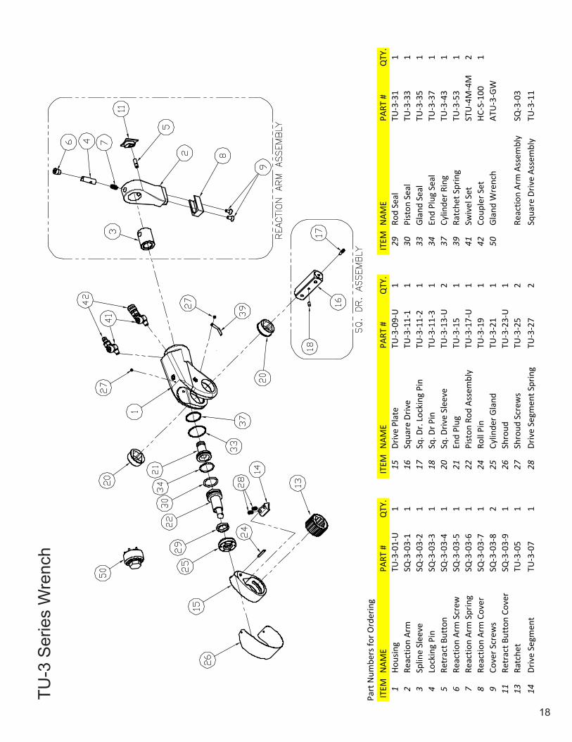
TU-3
Ser
ies
Wre
nch
ITEM
NAM
EPA
RT #
QTY
.IT
EMN
AME
PART
#Q
TY.
ITEM
NAM
EPA
RT #
QTY
.1
Hous
ing
TU-3
-01-
U1
15Dr
ive
Plat
eTU
-3-0
9-U
129
Rod
Seal
TU-3
-31
12
Reac
tion
Arm
SQ-3
-03-
11
16Sq
uare
Driv
eTU
-3-1
1-1
130
Pist
on S
eal
TU-3
-33
13
Splin
e Sl
eeve
SQ-3
-03-
21
17Sq
. Dr.
Lock
ing
Pin
TU-3
-11-
21
33Gl
and
Seal
TU-3
-35
14
Lock
ing
Pin
SQ-3
-03-
31
18Sq
. Dr P
inTU
-3-1
1-3
134
End
Plug
Sea
lTU
-3-3
71
5Re
trac
t But
ton
SQ-3
-03-
41
20Sq
. Driv
e Sl
eeve
TU-3
-13-
U2
37Cy
linde
r Rin
gTU
-3-4
31
6Re
actio
n Ar
m S
crew
SQ-3
-03-
51
21En
d Pl
ugTU
-3-1
51
39Ra
tche
t Spr
ing
TU-3
-53
17
Reac
tion
Arm
Spr
ing
SQ-3
-03-
61
22Pi
ston
Rod
Ass
embl
yTU
-3-1
7-U
141
Swiv
el S
etST
U-4
M-4
M2
8Re
actio
n Ar
m C
over
SQ-3
-03-
71
24Ro
ll Pi
nTU
-3-1
91
42Co
uple
r Set
HC-S
-100
19
Cove
r Scr
ews
SQ-3
-03-
82
25Cy
linde
r Gla
ndTU
-3-2
11
50Gl
and
Wre
nch
ATU
-3-G
W11
Retr
act B
utto
n Co
ver
SQ-3
-03-
91
26Sh
roud
TU-3
-23-
U1
13Ra
tche
tTU
-3-0
51
27Sh
roud
Scr
ews
TU-3
-25
2Re
actio
n Ar
m A
ssem
bly
SQ-3
-03
14Dr
ive
Segm
ent
TU-3
-07
128
Driv
e Se
gmen
t Spr
ing
TU-3
-27
2Sq
uare
Driv
e As
sem
bly
TU-3
-11
Part
Num
bers
for O
rder
ing
19
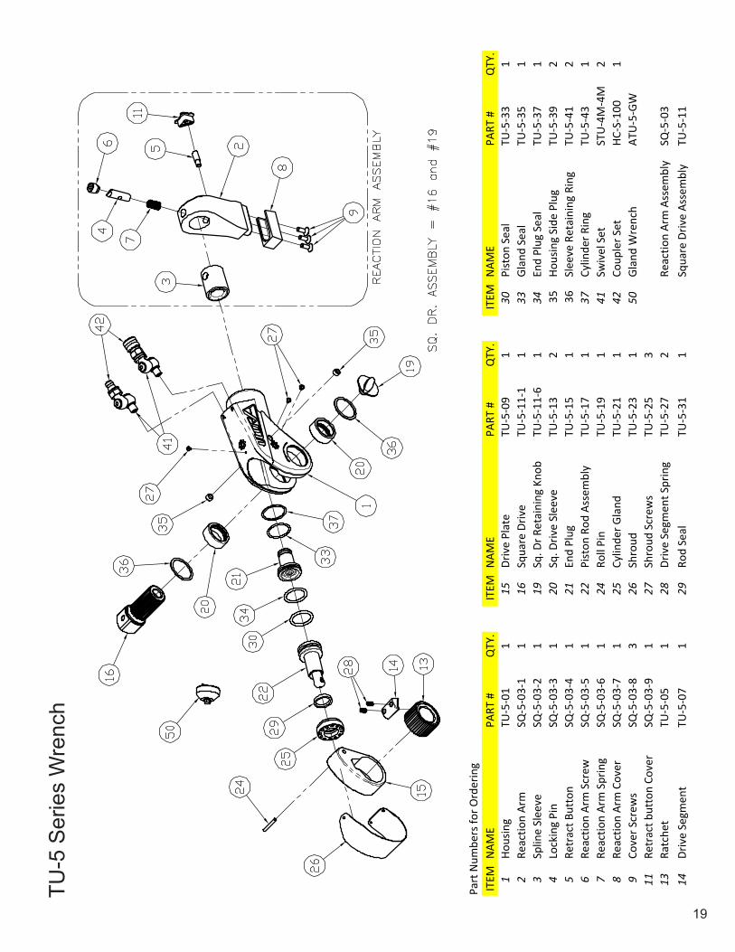
TU-5
Ser
ies
Wre
nch
ITEM
NAM
EPA
RT #
QTY
.IT
EMN
AME
PART
#Q
TY.
ITEM
NAM
EPA
RT #
QTY
.1
Hous
ing
TU-5
-01
115
Driv
e Pl
ate
TU-5
-09
130
Pist
on S
eal
TU-5
-33
12
Reac
tion
Arm
SQ-5
-03-
11
16Sq
uare
Driv
eTU
-5-1
1-1
133
Glan
d Se
alTU
-5-3
51
3Sp
line
Slee
veSQ
-5-0
3-2
119
Sq. D
r Ret
aini
ng K
nob
TU-5
-11-
61
34En
d Pl
ug S
eal
TU-5
-37
14
Lock
ing
Pin
SQ-5
-03-
31
20Sq
. Driv
e Sl
eeve
TU-5
-13
235
Hous
ing
Side
Plu
gTU
-5-3
92
5Re
trac
t But
ton
SQ-5
-03-
41
21En
d Pl
ugTU
-5-1
51
36Sl
eeve
Ret
aini
ng R
ing
TU-5
-41
26
Reac
tion
Arm
Scr
ewSQ
-5-0
3-5
122
Pist
on R
od A
ssem
bly
TU-5
-17
137
Cylin
der R
ing
TU-5
-43
17
Reac
tion
Arm
Spr
ing
SQ-5
-03-
61
24Ro
ll Pi
nTU
-5-1
91
41Sw
ivel
Set
STU
-4M
-4M
28
Reac
tion
Arm
Cov
erSQ
-5-0
3-7
125
Cylin
der G
land
TU-5
-21
142
Coup
ler S
etHC
-S-1
001
9Co
ver S
crew
sSQ
-5-0
3-8
326
Shro
udTU
-5-2
31
50Gl
and
Wre
nch
ATU
-5-G
W11
Retr
act b
utto
n Co
ver
SQ-5
-03-
91
27Sh
roud
Scr
ews
TU-5
-25
313
Ratc
het
TU-5
-05
128
Driv
e Se
gmen
t Spr
ing
TU-5
-27
2Re
actio
n Ar
m A
ssem
bly
SQ-5
-03
14Dr
ive
Segm
ent
TU-5
-07
129
Rod
Seal
TU-5
-31
1Sq
uare
Driv
e As
sem
bly
TU-5
-11
Part
Num
bers
for O
rder
ing
20
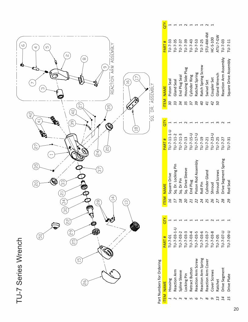
TU-7
Ser
ies
Wre
nch
ITEM
NAM
EPA
RT #
QTY
.IT
EMN
AME
PART
#Q
TY.
ITEM
NAM
EPA
RT #
QTY
.1
Hous
ing
TU-7
-01
116
Squa
re D
rive
TU-7
-11-
1-U
130
Pist
on S
eal
TU-7
-33
12
Reac
tion
Arm
TU-7
-03-
1-U
117
Sq. D
r. Lo
ckin
g Pi
nTU
-7-1
1-2
133
Glan
d Se
alTU
-7-3
51
3Sp
line
Slee
veTU
-7-0
3-2
118
Sq. D
r Pin
TU-7
-11-
31
34En
d Pl
ug S
eal
TU-7
-37
14
Lock
ing
Pin
TU-7
-03-
31
20Sq
. Driv
e Sl
eeve
TU-7
-13
235
Hous
ing
Side
Plu
gTU
-7-3
92
5Re
trac
t But
ton
TU-7
-03-
41
21En
d Pl
ugTU
-7-1
5-U
137
Cylin
der R
ing
TU-7
-43
16
Reac
tion
Arm
Scr
ewTU
-7-0
3-5
122
Pist
on R
od A
ssem
bly
TU-7
-17-
U1
39Ra
tche
t Spr
ing
TU-7
-53
17
Reac
tion
Arm
Spr
ing
TU-7
-03-
61
24Ro
ll Pi
nTU
-7-1
91
40Ra
tch
Sprin
g Sc
rew
TU-7
-25
18
Reac
tion
Arm
Cov
erTU
-7-0
3-7
125
Cylin
der G
land
TU-7
-21
141
Swiv
el S
etST
U-4
M-4
M2
9Co
ver S
crew
sTU
-7-0
3-8
226
Shro
udTU
-7-2
3-U
142
Coup
ler S
etHC
-S-1
001
13Ra
tche
tTU
-7-0
51
27Sh
roud
Scr
ews
TU-7
-25
350
Glan
d W
renc
hAT
U-7
-GW
14Dr
ive
Segm
ent
TU-7
-07-
U1
28Dr
ive
Segm
ent S
prin
gTU
-7-2
72
Reac
tion
Arm
Ass
embl
yTU
-7-0
315
Driv
e Pl
ate
TU-7
-09-
U1
29Ro
d Se
alTU
-7-3
11
Squa
re D
rive
Asse
mbl
yTU
-7-1
1
Part
Num
bers
for O
rder
ing

21
TU-1
1 S
erie
s W
renc
h
ITEM
NAM
EPA
RT #
QTY
.IT
EMN
AME
PART
#Q
TY.
ITEM
NAM
EPA
RT #
QTY
.1
Hous
ing
TU-1
1-01
-U1
15Dr
ive
Plat
eTU
-11-
09-U
130
Pist
on S
eal
TU-1
1-33
12
Reac
tion
Arm
SQ-1
0-03
-11
16Sq
uare
Driv
eTU
-11-
11-1
133
Glan
d Se
alTU
-11-
351
3Sp
line
Slee
veSQ
-10-
03-2
117
Sq. D
r. Lo
ckin
g Pi
nTU
-11-
11-2
134
End
Plug
Sea
lTU
-11-
371
4Lo
ckin
g Pi
nSQ
-10-
03-3
118
Sq. D
r Pin
TU-1
1-11
-31
35Ho
usin
g Si
de P
lug
TU-1
1-39
25
Retr
act B
utto
nSQ
-10-
03-4
120
Sq. D
rive
Slee
veTU
-11-
132
37Cy
linde
r Rin
gTU
-11-
431
6Re
actio
n Ar
m S
crew
SQ-1
0-03
-51
21En
d Pl
ugTU
-11-
151
39Ra
tche
t Spr
ing
TU-1
1-53
17
Reac
tion
Arm
Spr
ing
SQ-1
0-03
-61
22Pi
ston
Rod
Ass
embl
yTU
-11-
171
40Ra
tch
Sprin
g Sc
rew
TU-1
1-25
18
Reac
tion
Arm
Cov
erSQ
-10-
03-7
124
Roll
Pin
TU-1
1-19
141
Swiv
el S
etST
U-4
M-4
M2
9Co
ver S
crew
sSQ
-10-
03-8
225
Cylin
der G
land
TU-1
1-21
142
Coup
ler S
etHC
-S-1
001
11Re
trac
t But
ton
Cove
rSQ
-10-
03-9
126
Shro
udTU
-11-
231
12Re
t. Bu
tton
Gui
de S
crew
SQ-1
0-03
-10
127
Shro
ud S
crew
sTU
-11-
254
50Gl
and
Wre
nch
ATU
-11-
GW13
Ratc
het
TU-1
1-05
128
Driv
e Se
gmen
t Spr
ing
TU-1
1-27
2Re
actio
n Ar
m A
ssem
bly
SQ-1
0-03
14Dr
ive
Segm
ent
TU-1
1-07
129
Rod
Seal
TU-1
1-31
1Sq
uare
Driv
e As
sem
bly
TU-1
1-11
Part
Num
bers
for O
rder
ing

22
TU-2
0 S
erie
s W
renc
h
ITEM
NAM
EPA
RT #
QTY
.IT
EMN
AME
PART
#Q
TY.
ITEM
NAM
EPA
RT #
QTY
.1
Hous
ing
TU-2
0-01
115
Driv
e Se
gmen
tTU
-20-
071
29Pi
ston
Sea
lTU
-20-
341
2Sp
line
Slee
veTU
-20-
021
16Dr
ive
Plat
eTU
-20-
091
30Gl
and
Seal
TU-2
0-35
13
Reac
tion
Arm
TU-2
0-03
-01
117
Squa
re D
rive
TU-2
0-11
-11
31En
d Pl
ug S
eal
TU-2
0-37
14
Gate
TU-2
0-03
-02
118
Sq D
r Ret
aini
ng K
nob
TU-2
0-11
-81
32Ho
usin
g Si
de P
lug
TU-2
0-39
25
Gate
Lev
er L
ink
TU-2
0-03
-03
119
Squa
re D
rive
Slee
veTU
-20-
132
33Sl
eeve
Ret
aini
ng R
ing
TU-2
0-41
26
Gate
Lev
erTU
-20-
03-0
41
20En
d Pl
ugTU
-20-
151
34Cy
linde
r Rin
gTU
-20-
431
7Ga
te L
ever
Spa
cer
TU-2
0-03
-05
221
Pist
on R
od A
ssem
bly
TU-2
0-17
135
Slee
ve O
-Rin
gTU
-20-
512
8Ga
te B
olt
TU-2
0-03
-06
122
Retr
act S
crew
TU-2
0-19
236
Swiv
el S
etST
U-4
M-4
M2
9Re
actio
n Ar
m C
over
TU-2
0-03
-07
123
Cylin
der G
land
TU-2
0-21
137
Coup
ler S
etHC
-S-1
001
10Ga
te L
ink
Pin
TU-2
0-03
-08
224
Shro
udTU
-20-
231
11Ga
te L
ever
Pin
TU-2
0-03
-09
125
Shro
ud S
crew
TU-2
0-25
450
Glan
d W
renc
hAT
U-2
0-GW
12Ga
te S
prin
gTU
-20-
03-1
01
26Dr
ive
Segm
ent S
prin
gTU
-20-
272
13Co
ver R
oll P
inTU
-20-
03-1
11
27Ro
d Se
alTU
-20-
311
Reac
tion
Arm
Ass
embl
yTU
-20-
0314
Ratc
het
TU-2
0-05
128
Pist
on U
-Cup
Sea
lTU
-20-
331
Squa
re D
rive
Asse
mbl
yTU
-20-
11
Part
Num
bers
for O
rder
ing
23
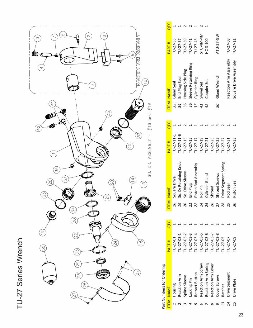
TU-2
7 S
erie
s W
renc
h
ITEM
NAM
EPA
RT #
QTY
.IT
EMN
AME
PART
#Q
TY.
ITEM
NAM
EPA
RT #
QTY
.1
Hous
ing
TU-2
7-01
116
Squa
re D
rive
TU-2
7-11
-11
33Gl
and
Seal
TU-2
7-35
12
Reac
tion
Arm
TU-2
7-03
-11
19Sq
. Dr R
etai
ning
Kno
bTU
-27-
11-6
134
End
Plug
Sea
lTU
-27-
371
3Sp
line
Slee
veTU
-27-
03-2
120
Sq. D
rive
Slee
veTU
-27-
132
35Ho
usin
g Si
de P
lug
TU-2
7-39
24
Lock
ing
Pin
TU-2
7-03
-31
21En
d Pl
ugTU
-27-
151
36Sl
eeve
Ret
aini
ng R
ing
TU-2
7-41
25
Retr
act B
utto
nTU
-27-
03-4
122
Pist
on R
od A
ssem
bly
TU-2
7-17
137
Cylin
der R
ing
TU-2
7-43
16
Reac
tion
Arm
Scr
ewTU
-27-
03-5
124
Roll
Pin
TU-2
7-19
141
Swiv
el S
etST
U-4
M-4
M2
7Re
actio
n Ar
m S
prin
gTU
-27-
03-6
125
Cylin
der G
land
TU-2
7-21
142
Coup
ler S
etHC
-S-1
001
8Re
actio
n Ar
m C
over
TU-2
7-03
-71
26Sh
roud
TU-2
7-23
19
Cove
r Scr
ews
TU-2
7-03
-82
27Sh
roud
Scr
ews
TU-2
7-25
450
Glan
d W
renc
hAT
U-2
7-GW
13Ra
tche
tTU
-27-
051
28Dr
ive
Segm
ent S
prin
gTU
-27-
272
14Dr
ive
Segm
ent
TU-2
7-07
129
Rod
Seal
TU-2
7-31
1Re
actio
n Ar
m A
ssem
bly
TU-2
7-03
15Dr
ive
Plat
eTU
-27-
091
30Pi
ston
Sea
lTU
-27-
331
Squa
re D
rive
Asse
mbl
yTU
-27-
11
Part
Num
bers
for O
rder
ing
24
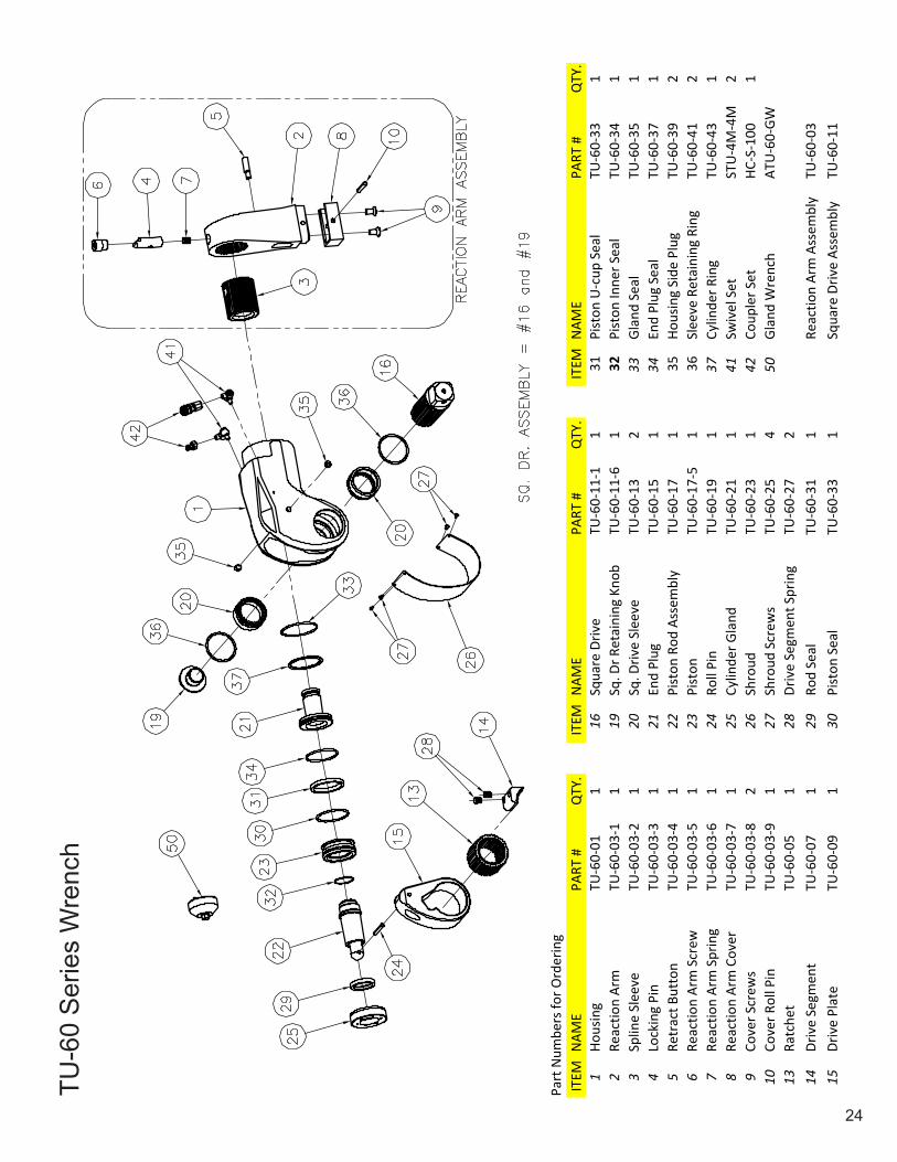
TU-6
0 S
erie
s W
renc
h
ITEM
NAM
EPA
RT #
QTY
.IT
EMN
AME
PART
#Q
TY.
ITEM
NAM
EPA
RT #
QTY
.1
Hous
ing
TU-6
0-01
116
Squa
re D
rive
TU-6
0-11
-11
31Pi
ston
U-c
up S
eal
TU-6
0-33
12
Reac
tion
Arm
TU-6
0-03
-11
19Sq
. Dr R
etai
ning
Kno
bTU
-60-
11-6
132
Pist
on In
ner S
eal
TU-6
0-34
13
Splin
e Sl
eeve
TU-6
0-03
-21
20Sq
. Driv
e Sl
eeve
TU-6
0-13
233
Glan
d Se
alTU
-60-
351
4Lo
ckin
g Pi
nTU
-60-
03-3
121
End
Plug
TU-6
0-15
134
End
Plug
Sea
lTU
-60-
371
5Re
trac
t But
ton
TU-6
0-03
-41
22Pi
ston
Rod
Ass
embl
yTU
-60-
171
35Ho
usin
g Si
de P
lug
TU-6
0-39
26
Reac
tion
Arm
Scr
ewTU
-60-
03-5
123
Pist
onTU
-60-
17-5
136
Slee
ve R
etai
ning
Rin
gTU
-60-
412
7Re
actio
n Ar
m S
prin
gTU
-60-
03-6
124
Roll
Pin
TU-6
0-19
137
Cylin
der R
ing
TU-6
0-43
18
Reac
tion
Arm
Cov
erTU
-60-
03-7
125
Cylin
der G
land
TU-6
0-21
141
Swiv
el S
etST
U-4
M-4
M2
9Co
ver S
crew
sTU
-60-
03-8
226
Shro
udTU
-60-
231
42Co
uple
r Set
HC-S
-100
110
Cove
r Rol
l Pin
TU-6
0-03
-91
27Sh
roud
Scr
ews
TU-6
0-25
450
Glan
d W
renc
hAT
U-6
0-GW
13Ra
tche
tTU
-60-
051
28Dr
ive
Segm
ent S
prin
gTU
-60-
272
14Dr
ive
Segm
ent
TU-6
0-07
129
Rod
Seal
TU-6
0-31
1Re
actio
n Ar
m A
ssem
bly
TU-6
0-03
15Dr
ive
Plat
eTU
-60-
091
30Pi
ston
Sea
lTU
-60-
331
Squa
re D
rive
Asse
mbl
yTU
-60-
11
Part
Num
bers
for O
rder
ing

25
TU Series Wrench Available Accessories
26
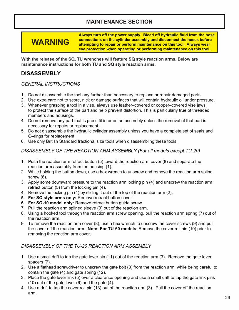
MAINTENANCE SECTION
Always turn off the power supply. Bleed off hydraulic fluid from the hose connections on the cylinder assembly and disconnect the hoses before attempting to repair or perform maintenance on this tool. Always wear eye protection when operating or performing maintenance on this tool.
DISASSEMBLY
GENERAL INSTRUCTIONS
1. Do not disassemble the tool any further than necessary to replace or repair damaged parts.2. Use extra care not to score, nick or damage surfaces that will contain hydraulic oil under pressure.3. Whenever grasping a tool in a vise, always use leather–covered or copper–covered vise jaws
to protect the surface of the part and help prevent distortion. This is particularly true of threaded members and housings.
4. Donotremoveanypartthatispressfitinoronanassemblyunlesstheremovalofthatpartisnecessary for repairs or replacement.
5. Do not disassemble the hydraulic cylinder assembly unless you have a complete set of seals and O–rings for replacement.
6. Use only British Standard fractional size tools when disassembling these tools.
DISASSEMBLY OF THE REACTION ARM ASSEMBLY (For all models except TU-20)
1. Push the reaction arm retract button (5) toward the reaction arm cover (8) and separate the reaction arm assembly from the housing (1).
2. While holding the button down, use a hex wrench to unscrew and remove the reaction arm spline screw (6).
3. Apply some downward pressure to the reaction arm locking pin (4) and unscrew the reaction arm retract button (5) from the locking pin (4).
4. Remove the locking pin (4) by sliding it out of the top of the reaction arm (2).5. For SQ style arms only: Remove retract button cover.6. For SQ-10 model only: Remove retract button guide screw. 7. Pull the reaction arm splined sleeve (3) out of the reaction arm.8. Using a hooked tool through the reaction arm screw opening, pull the reaction arm spring (7) out of
the reaction arm.9. To remove the reaction arm cover (8), use a hex wrench to unscrew the cover screws (9) and pull
the cover off the reaction arm. Note: For TU-60 models: Remove the cover roll pin (10) prior to removing the reaction arm cover.
DISASSEMBLY OF THE TU-20 REACTION ARM ASSEMBLY
1. Use a small drift to tap the gate lever pin (11) out of the reaction arm (3). Remove the gate lever spacers (7).
2. Useaflatheadscrewdrivertounscrewthegatebolt(8)fromthereactionarm,whilebeingcarefultocontain the gate (4) and gate spring (12).
3. Place the gate lever link (5) over a clearance opening and use a small drift to tap the gate link pins (10) out of the gate lever (6) and the gate (4).
4. Use a drift to tap the cover roll pin (13) out of the reaction arm (3). Pull the cover off the reaction arm.
WARNING
With the release of the SQ, TU wrenches will feature SQ style reaction arms. Below are maintenance instructions for both TU and SQ style reaction arms.

27
DISASSEMBLY OF THE TU-2, TU-3, TU-7, AND TU-11 CYLINDER ASSEMBLIES
1. Clamp the housing (1) in copper–covered or leather–covered vise jaws with the inlet end upward and using a 1/4” hex wrench, unscrew and remove the two swivels (41) with their attached couplers (42).
2. Remove the housing assembly from the vise jaws and turn over a container to catch any oil remaining inside the cylinder.
3. Use a hex wrench to unscrew and remove the shroud mounting screws (27). Remove the shroud (26). Note: For TU-3 models, the drive side shroud screw holds the ratchet spring (39) in place, which will come out with the removal of the shroud.
4. For TU-7 and TU-11 models, use a hex wrench to unscrew and remove the side housing plugs (35) from each side of the housing.
5. If the piston assembly is not fully retracted, use a brass drift or brass hammer to tap the assembly inward until the roll pin (24) aligns with the cross holes in the housing. Note: Covering the inlets with a cloth will contain any oil that may expel from the housing.
6. Use a small drift to tap the roll pin (24) out of the piston rod assembly (22) and drive plate (15). 7. Insert a hex wrench through the larger opening in the square drive and loosen the square drive
locking pin (17) until the square drive slides out of the tool. Note: Use caution when removing the square drive.Thesquaredrivepin(18)looselyfitsinthesquaredriveandcanfalloutwhenthe drive is removed.
8. Remove the drive plate (15), assembled with the ratchet (13), drive segment (14) and segment springs (28).
9. Usingfingerpressure,pushthesleeves(20)inwardtoremovethemfromthehousing.10. Being careful not to let the springs eject from the assembly, slide the ratchet (13), drive segment
(14) and segment springs (28) out of the drive plate (15).
11. Locate the stake point on the threads of the cylinder gland (25) and housing. Using a 1/16” drill bit centered on the stake point, drill approximately 3/32” deep in one continuous motion to remove the thread and interference at that point.
12. Engage the pins of the cylinder gland wrench (50) with the holes in the cylinder gland (25) and using a socket on the hex of the wrench unscrew and remove the cylinder gland. If the gland does not rotate freely after initial breakout, additional drilling, in small increments, may be required to remove the obstruction.
13. Clamp the housing in the vise with the end plug upward and a catch cloth draped between the jaws.14. Insertaflatfacedriftintotheholeinthecenteroftheendplug(21).Taptheendplugandpiston
lightly until both the piston and end plug slip through the housing and into the catch cloth. 15. While using caution as to avoid scratching the cylinder, remove the cylinder ring (37) by using a thin
blade screwdriver to work it out of the groove within the housing.
In the following step, the shroud will spring to a straightened position when the screws at one end are removed. Hold the shroud in position until the screws are removed and control the flex of the loose end.
The cylinder gland is staked into the housing to prevent it from loosening due to vibration or turbulence in the hydraulic oil flow. The stake point must be drilled out before attempting to remove the cylinder gland.
MAINTENANCE SECTION
CAUTION
NOTICE

28
DISASSEMBLY OF THE TU-5, TU-20, TU-27, AND TU-60 CYLINDER ASSEMBLIES Note: TU-20 part numbers are bold.1. Clamp the housing (1) (1) in copper–covered or leather–covered vise jaws with the inlet end
upward. Use a 1/4” hex wrench to unscrew and remove the two swivels (41) (36) with their attached couplers (42) (37).
2. Remove the housing assembly from the vise jaws, and turn over a container to catch any oil remaining inside the cylinder.
3. Use a hex wrench to unscrew and remove the shroud mounting screws (27) (25). Remove the shroud (26) (24).
4. Use a hex wrench to unscrew and remove the side housing plugs (35) (32) from each side of the housing.
5. If the piston assembly is not fully retracted, use a brass drift or brass hammer to tap the assembly inward until the roll pin (24) aligns with the cross holes in the housing. Note: Covering the inlets with a cloth will contain any oil that may expel from the housing.
6. Use a small drift to tap the roll pin (24) out of the piston rod assembly (22) and drive plate (15). Note: For TU-20 models, retract screws (22) are used in the place of the roll pin. Use a hex wrench to remove the retract screws from the drive plate.
7. Unscrew the square drive retaining knob (19) (18). Pull out the square drive (16) (17).8. Remove the drive plate (15) (16), assembled with the ratchet (13) (14), drive segment (14) (15)
and segment springs (28) (26).9. Usingfingerpressure,pushthesleeves(20) (19) inward to remove them from the housing.
Remove the sleeve retainers (36) (33). 10. Being careful not to let the segment springs (28) (26) eject from the assembly, slide the ratchet
(13) (14), drive segment (14) (15), and segment springs (28) (26) out of the drive plate (15) (16).11. Locate the stake point on the threads of the cylinder gland (25) (23) and housing. Using a 1/16”
drill bit centered on the stake point, drill approximately 3/32” deep in one continuous motion to remove the thread and interference at that point.
12. Engage the pins of the cylinder gland wrench (50) (50) with the holes in the cylinder gland (25) (23). Use a socket on the hex of the wrench to unscrew and remove the cylinder gland. If the gland does not rotate freely after initial breakout, additional drilling, in small increments, may be required to remove the obstruction.
13. Clamp the housing in the vise with the end plug upward and a catch cloth draped between the jaws.
14. For TU-20 models, use a 1” square drive extension and an adjustable wrench to unscrew the end plug (20) from the spline sleeve (2). Pull the spline sleeve from the housing.
15. Insertaflatfacedriftintotheholeinthecenteroftheendplug(21)(20). Tap the end plug and piston lightly until both the piston and end plug slip through the housing and into the catch cloth.
16. While using caution as to avoid scratching the cylinder, remove the cylinder ring (37) (34) using a thin blade screwdriver to work it out of the groove within the housing.
MAINTENANCE SECTION
In the following step, the shroud will spring to a straightened position when the screws at one end are removed. Hold the shroud in position until the screws are removed and control the flex of the loose end.CAUTION
29
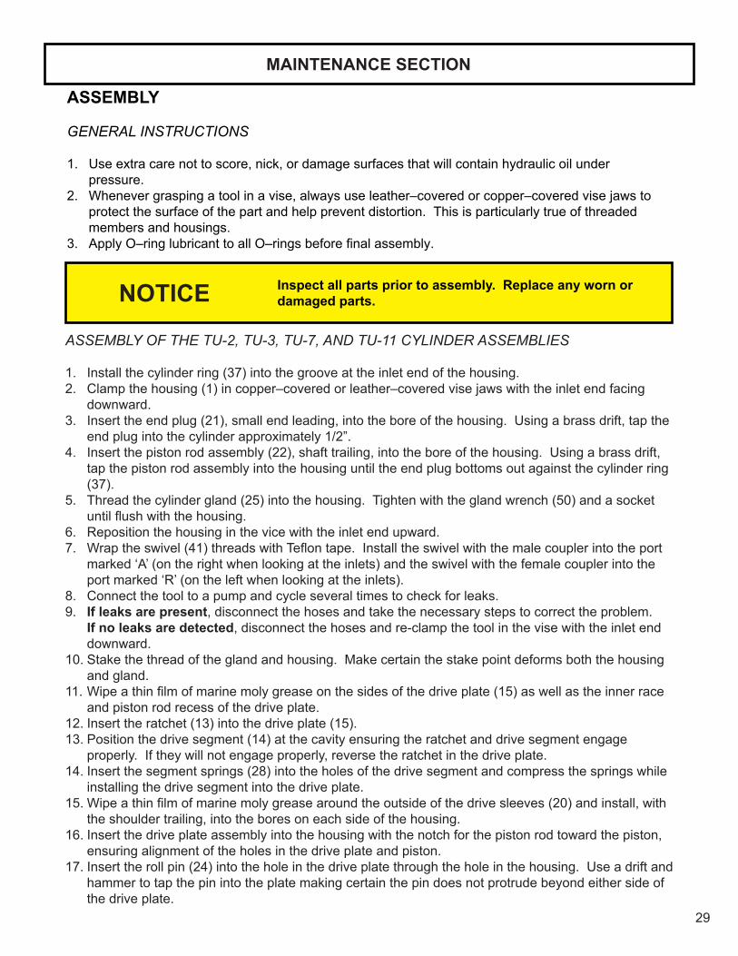
ASSEMBLY
GENERAL INSTRUCTIONS
1. Use extra care not to score, nick, or damage surfaces that will contain hydraulic oil under pressure.
2. Whenever grasping a tool in a vise, always use leather–covered or copper–covered vise jaws to protect the surface of the part and help prevent distortion. This is particularly true of threaded members and housings.
3. ApplyO–ringlubricanttoallO–ringsbeforefinalassembly.
Inspect all parts prior to assembly. Replace any worn or damaged parts.
MAINTENANCE SECTION
ASSEMBLY OF THE TU-2, TU-3, TU-7, AND TU-11 CYLINDER ASSEMBLIES
1. Install the cylinder ring (37) into the groove at the inlet end of the housing.2. Clamp the housing (1) in copper–covered or leather–covered vise jaws with the inlet end facing
downward.3. Insert the end plug (21), small end leading, into the bore of the housing. Using a brass drift, tap the
end plug into the cylinder approximately 1/2”.4. Insert the piston rod assembly (22), shaft trailing, into the bore of the housing. Using a brass drift,
tap the piston rod assembly into the housing until the end plug bottoms out against the cylinder ring (37).
5. Thread the cylinder gland (25) into the housing. Tighten with the gland wrench (50) and a socket untilflushwiththehousing.
6. Reposition the housing in the vice with the inlet end upward.7. Wraptheswivel(41)threadswithTeflontape.Installtheswivelwiththemalecouplerintotheport
marked ‘A’ (on the right when looking at the inlets) and the swivel with the female coupler into the port marked ‘R’ (on the left when looking at the inlets).
8. Connect the tool to a pump and cycle several times to check for leaks. 9. If leaks are present, disconnect the hoses and take the necessary steps to correct the problem.
If no leaks are detected, disconnect the hoses and re-clamp the tool in the vise with the inlet end downward.
10. Stake the thread of the gland and housing. Make certain the stake point deforms both the housing and gland.
11. Wipeathinfilmofmarinemolygreaseonthesidesofthedriveplate(15)aswellastheinnerraceand piston rod recess of the drive plate.
12. Insert the ratchet (13) into the drive plate (15).13. Position the drive segment (14) at the cavity ensuring the ratchet and drive segment engage
properly. If they will not engage properly, reverse the ratchet in the drive plate.14. Insert the segment springs (28) into the holes of the drive segment and compress the springs while
installing the drive segment into the drive plate.15. Wipeathinfilmofmarinemolygreasearoundtheoutsideofthedrivesleeves(20)andinstall,with
the shoulder trailing, into the bores on each side of the housing.16. Insert the drive plate assembly into the housing with the notch for the piston rod toward the piston,
ensuring alignment of the holes in the drive plate and piston.17. Insert the roll pin (24) into the hole in the drive plate through the hole in the housing. Use a drift and
hammer to tap the pin into the plate making certain the pin does not protrude beyond either side of the drive plate.
NOTICE

30
MAINTENANCE SECTION
18. Use a hex wrench to loosen the square drive locking pin (17) enough so that the square drive pin isflushwiththesquaredrive.
19. Insert the square drive into the housing through the drive sleeves (20) and tighten the drive locking pin so that the square drive can slide freely without sliding out.
20. Place one end of the shroud (26) on the housing and, using a hex wrench, thread the shroud screws (27) part way in.
21. Bend the shroud around the housing and install the remaining screws, going back and tightening the screws from the previous step.
Inspect all parts prior to assembly. Replace any worn or damaged parts.
ASSEMBLY OF THE TU-5, TU-20, TU-27, AND TU-60 CYLINDER ASSEMBLIES
Note: TU-20 part numbers are bold.1. Install the cylinder ring (37) (34) into the groove at the inlet end of the housing.2. Clamp the housing (1) (1) in copper–covered or leather–covered vise jaws with the inlet end
downward.3. Insert the end plug (21) (20), small end leading, into the bore of the housing. Using a brass drift,
tap the end plug into the cylinder approximately 1/2”.4. Insert the piston rod assembly (22) (21), shaft trailing, into the bore of the housing. Using a brass
drift, tap the piston rod assembly into the housing until the end plug bottoms out against the cylinder ring.
5. Thread the cylinder gland (25) (23) into the housing. Tighten with the gland wrench (50) (50) and a socketuntilflushwiththehousing.
6. Reposition the housing in the vice with the inlet end upward.7. For TU-20 models, insert the splined sleeve (2) into the housing with the groove trailing. Insert a 1”
square drive extension through the splined sleeve and into the end plug (20). Screw the end plug into the splined sleeve until snug. Light lubrication on the spline sleeve will ease installation.
8. Wrap the swivel (41) (36)threadswithTeflontape.Installtheswivelwiththemalecouplerintotheport marked ‘A’ (on the right when looking at the inlets) and the swivel with the female coupler into the port marked ‘R’ (on the left when looking at the inlets).
9. Connect the tool to a pump and cycle several times to check for leaks. 10. If leaks are present, disconnect the hoses and take the necessary steps to correct the problem.
If no leaks are detected, disconnect the hoses and re-clamp the tool in the vise with the inlet end downward.
11. Stake the thread of the gland and housing. Make certain the stake point deforms both the housing and gland.
12. Wipeathinfilmofmarinemolygreaseonthesidesofthedriveplate(15)(16) as well as the inner race and piston rod recess of the drive plate.
13. Insert the ratchet (13) (14) into the drive plate (15) (16).14. Position the drive segment (14) (15) at the cavity, ensuring the ratchet and drive segment engage
properly. If they will not engage properly, reverse the ratchet in the drive plate.15. Insert the segment springs (28) (26) into the holes of the drive segment and compress while
installing the drive segment into the drive plate.16. Insert the drive plate assembly into the housing with the notch for the piston rod toward the piston,
ensuring alignment of the holes in the drive plate and piston.
NOTICE

31
MAINTENANCE SECTION
17. Install the square drive sleeves (20) (19) with the small hub end leading. The small hub must engage the recess in the drive plate assembly. Install the sleeve retaining rings (36) (33).
18. Insert the square drive (16) (17) into the housing through the drive sleeves (20) (19). Install the square drive retaining knob (19) (18) in the end of the square drive and tighten.
19. Insert the roll pin (24) into the hole in the drive plate through the hole in the housing. Use a drift and hammer to tap the pin into the plate making certain the pin does not protrude beyond either side of the drive plate. Note: For TU-20 models, retract screws (22) are used in the place of the retract pin. Use a hex wrench to install into the drive plate.
20. Place one end of the shroud (26) (24) on the housing and, using a hex wrench, thread the shroud screws (27) (25) part way in.
21. Bend the shroud around the housing and install the remaining screws, going back and tightening the screws from the previous step.
32
MAINTENANCE SECTION
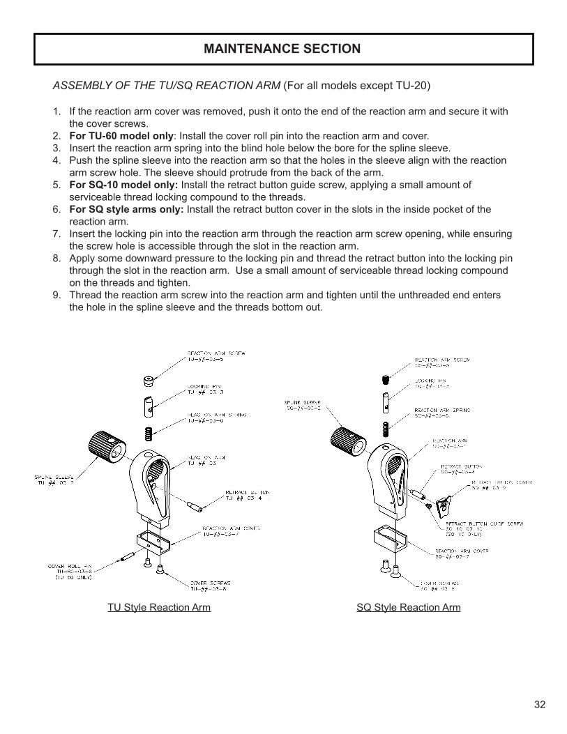
ASSEMBLY OF THE TU/SQ REACTION ARM (For all models except TU-20)
1. If the reaction arm cover was removed, push it onto the end of the reaction arm and secure it with the cover screws.
2. For TU-60 model only: Install the cover roll pin into the reaction arm and cover.3. Insert the reaction arm spring into the blind hole below the bore for the spline sleeve.4. Push the spline sleeve into the reaction arm so that the holes in the sleeve align with the reaction
arm screw hole. The sleeve should protrude from the back of the arm.5. For SQ-10 model only: Install the retract button guide screw, applying a small amount of
serviceable thread locking compound to the threads.6. For SQ style arms only: Install the retract button cover in the slots in the inside pocket of the
reaction arm.7. Insert the locking pin into the reaction arm through the reaction arm screw opening, while ensuring
the screw hole is accessible through the slot in the reaction arm.8. Apply some downward pressure to the locking pin and thread the retract button into the locking pin
through the slot in the reaction arm. Use a small amount of serviceable thread locking compound on the threads and tighten.
9. Thread the reaction arm screw into the reaction arm and tighten until the unthreaded end enters the hole in the spline sleeve and the threads bottom out.
TU Style Reaction Arm SQ Style Reaction Arm

33
MAINTENANCE SECTION
ASSEMBLY OF THE TU-20 REACTION ARM
1. If the reaction arm cover was removed, push it onto the end of the reaction arm and insert the cover roll pin to retain the cover using a hammer.
2. Assemble the gate lever to the gate lever link using the gate link pin. 3. Assemble the gate to the gate lever link using the second gate link pin. 4. Insert the gate spring into the gate.5. Hold the gate in the reaction arm and thread the gate bolt through the gate into the reaction
arm. Use a small amount of serviceable thread locking compound on the threads. Tighten with a screwdriver.
6. Place the gate lever spacers over the gate lever.7. Swing the gate lever and the link into the reaction arm with the gate lever spacers.8. Insert the gate lever pin into the reaction arm through the gate lever and the gate lever
spacers.
34
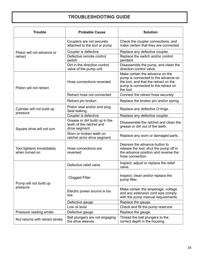
Trouble Probable Cause Solution
Piston will not advance or retract
Couplers are not securely attached to the tool or pump
Check the coupler connections, and make certain that they are connected.
Coupler is defective Replace any defective coupler.Defective remote control switch
Replace the switch and/or control pendent.
Dirt in the direction-control valve of the pump unit
Disassemble the pump, and clean the direction-control valve.
Piston will not retract
Hose connections reversed
Make certain the advance on the pump is connected to the advance on the tool, and that the retract on the pump is connected to the retract on the tool.
Retract hose not connected Connect the retract hose securely.
Retract pin broken Replace the broken pin and/or spring.
Cylinder will not build up pressure
Piston seal and/or end plug Seal leaking Replace any defective O-rings.
Coupler is defective Replace any defective coupler.
Square drive will not turn
Grease or dirt build up in the teeth of the ratchet and drive segment
Disassemble the ratchet and clean the grease or dirt out of the teeth.
Worn or broken teeth on ratchet an/or drive segment Replace any worn or damaged parts.
Tool tightens immediately when turned on
Hose connections are reversed
Depress the advance button to release the tool; shut the pump off in the advance position and reverse the hose connection.
Pump will not build up pressure
Defective relief valve Inspect, adjust or replace the relief valve.
Clogged Filter Inspect, clean and/or replace the pumpfilter.
Electric power source is too low
Make certain the amperage, voltage and any extension cord size comply with the pump manual requirements.
Defective gauge Replace the gauge.Low oil level Checkandfillthepumpreservoir.
Pressure reading erratic Defective gauge Replace the gauge.
Nut returns with retract stroke Ball plungers are not engaging the drive sleeves
Thread the ball plungers to the correct depth in the housing.
TROUBLESHOOTING GUIDE

SAVE THESE INSTRUCTIONS DO NOT DESTROY
NOTES:
Phone: +1 610-250-5800 Fax:+1 610-250-2700
Toll Free: 1-888-TORCUP-1Email: [email protected] Website: www.torcup.com
1025 Conroy Place, Easton, PA. 18040 U.S.A.