Embed Size (px)
Citation preview

Manual to use the simulator for
computer organization and
architecture
Developed by the Department of CSE, IIT kharagpur
This simulator has been developed as a virtual lab which is an initiative of Ministry of Human Resource and Development(MHRD) under National Mission of Education through ICT to provide an interactive environment over the internet for creating and conducting different laboratory experiments by sharing the costly equipments and the resources.

Introduction:
This simulator provides an interactive environment for creating and conducting simulated experiments on computer organization and architecture. It supports gate level design to CPU design.
Figure 1. Main interface of the simulator
Features of the simulator:
The main features of the simulators are as follows:
Logic:
The simulator supports 5 valued logic. So the simulator supports wired AND for bus based design. These 5 states along with their corresponding wire values are as follows:
• True (T) (wire color: blue) • False (F) (wire color: black) • High impedence (Z) (wire color: green) • Unknown (X) (wire color: maroon) • Invalid (I) (wire color: orange)
Truth table for 5 valued logic used in the simulator:

AND OR
NAND NOR
XOR XNOR
NOT Tri State Buffer
Graphical organization of the simulator:
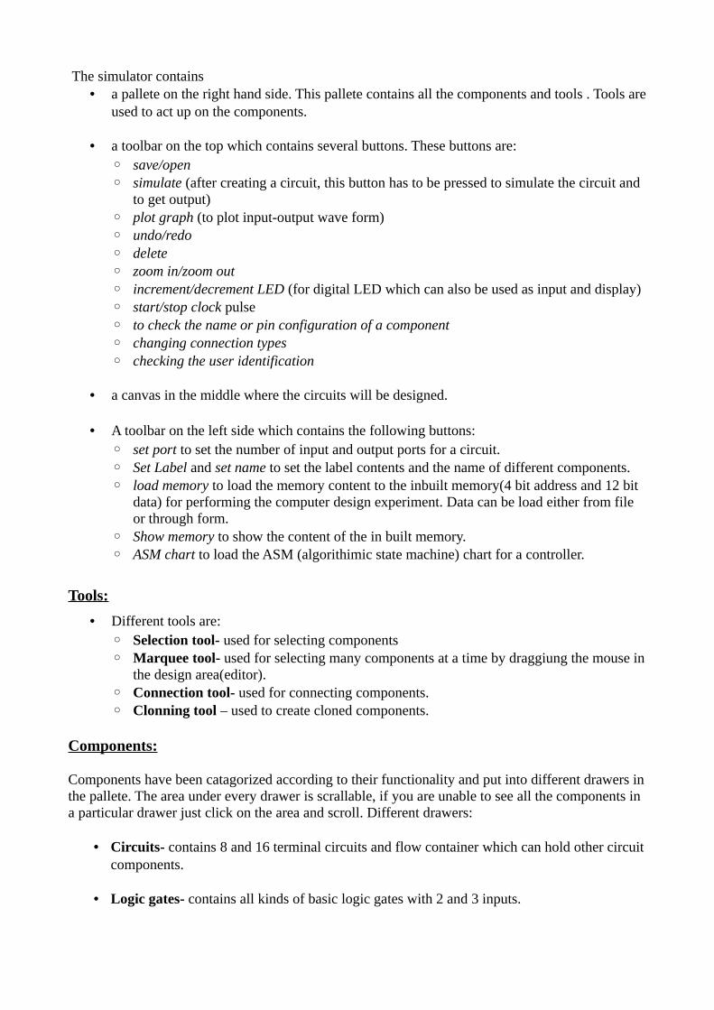
The simulator contains • a pallete on the right hand side. This pallete contains all the components and tools . Tools are
used to act up on the components.
• a toolbar on the top which contains several buttons. These buttons are: ◦ save/open◦ simulate (after creating a circuit, this button has to be pressed to simulate the circuit and
to get output)◦ plot graph (to plot input-output wave form)◦ undo/redo◦ delete◦ zoom in/zoom out ◦ increment/decrement LED (for digital LED which can also be used as input and display)◦ start/stop clock pulse◦ to check the name or pin configuration of a component◦ changing connection types◦ checking the user identification
• a canvas in the middle where the circuits will be designed.
• A toolbar on the left side which contains the following buttons:◦ set port to set the number of input and output ports for a circuit.◦ Set Label and set name to set the label contents and the name of different components.◦ load memory to load the memory content to the inbuilt memory(4 bit address and 12 bit
data) for performing the computer design experiment. Data can be load either from file or through form.
◦ Show memory to show the content of the in built memory.◦ ASM chart to load the ASM (algorithimic state machine) chart for a controller.
Tools:
• Different tools are:◦ Selection tool- used for selecting components ◦ Marquee tool- used for selecting many components at a time by draggiung the mouse in
the design area(editor). ◦ Connection tool- used for connecting components.◦ Clonning tool – used to create cloned components.
Components:
Components have been catagorized according to their functionality and put into different drawers in the pallete. The area under every drawer is scrallable, if you are unable to see all the components in a particular drawer just click on the area and scroll. Different drawers:
• Circuits- contains 8 and 16 terminal circuits and flow container which can hold other circuit components.
• Logic gates- contains all kinds of basic logic gates with 2 and 3 inputs.

• Display and inputs- contains all kinds of component needed to give input to the circuit along with free running clock and displaying outputs of the circuit.
• Adders- contains different types of adder circuits.
• Sequential ckt- contains basic flipflops, registers for designing sequential circuits.
• Other Components- contains different kinds of components like decoders, multiplexers, arithmetic logic units(ALU), memory elements(RAM cell), cache memory(without any replacement policy)required to design combinational circuits.
• Control Unit- contains a controller whose state table(Moore m/c) can be loaded from the interface.
• Computer Design- contains a single instruction CPU and a Memory (4 bit address and 12 bit data, can be loaded by user)
Building a circuit:
Adding components:
To add the components to the editor select any component(first click on the selection tool then click on the desired compoent) then finally click on the position of the editor window where you want to add the component.
Pin configuration for a pallete component:
The pin configuration of a component can be seen in two ways:• selecting the component and press the 'show pinconfig' button in the left toolbar• whenever the mouse is hovered on any canned component of the palette.
Pin numbering starts from 1 and from the bottom left corner(indicating with the circle) and increases anticlockwise.
Connecting components:
• To connect any two components select the Connection tool in the palette, and then click on the Source terminal and click on the target terminal(no drag and drop, simple click will serve the purpose).
• After the connection is over click the selection tool in the pallete. • To move any components select the Selection Mode and drag the component after selecting
it. • Users can connect only from a source terminal to the destination terminal. This facility
prevents the user from design errors.• Any input terminal can be connected only once, but any output terminal can be connected to
multiple number of terminals.• For any component, all the upper terminals are input terminals and all lower terminals are
output terminals.• At any time instant, the value of a wire is denoted by the wire color. As the simulator
supports 5 valued logic, a wire may have 5 different colors.

• Initially the wire value is set to unknown• specific wire colors for 5 different states have been given at the begining of this manual.
Other functionalities:
• undo, redo, delete, zoom in, zoom out facilities are provided.
• Users can save their circuits with .logic extension and reuse them.
• User can load data through interface or can load from text file. The text file must contains only binary values. The whole row of a data must be written in seperate line. For example:
◦ if memory location 0011 should contain a word of 100101111001, then the fourth line of the text file must contain only 100101111001. on other data should be written in that line.
Figure 2. Interface to load memory for computer design experiment
• For loading ASM chart, enter the number of states, inputs and output control signals. The name of the control signals can be changhed as per the requirement. Now, the state table can be added using the drop down box as shown in Figure 3.

Figure 3. Interface to load state chart (ASM chart) to the controller for computer design experiment
• The circuit drawer contains a label component, which can be used to keep any note in the canvas during circuit design.
Figure 4. Screenshot of a running 4 bit shift register made up of master slave flipflops with a label at the bottom

Simulationg a circuit:
• After building the circuit press the simulate button in the top toolbar to get the output.
• If the circuit contains a clock pulse input, then the 'start clock' button will start the simulation of the whole circuit. Then there is no need to again press the 'simulate' button.
• If the circuit contains multiple clock inputs, then select all of them using control key then press start clok button. Start clock button will generate contineous pulses to all the selected clock components, if any of the clock pulse is needed to be fixed in the desired value, then press control button and deselect the desired clock component. For starting again the deselected clock component press control key and select it.
• The plot graph button will give the input-output wave form of the circuit for a simulation. So if the circuit contains free running clock then the circuit will keep simulating itself and will generate a contineous wave form as shown in the following screenshot:
Figure 5. A small circuit with gates, free running clock, bit display and contineous wave form
Limitations:
• Due to 5 valued logic gate level flipflop design is not supported by this simulator at present time. For designing sequential circuits, all types flipflops are provided as a module.

Description of Components:
General components:
1. Digital display: it can be used to give input and as well as to see the output in the decimal format, its right most terminal is the LSB(least significant bit) and the left most terminal is the MSB(most significant bit), in the editor after selecting a particular digital display you can use 'Increment LED' and 'Decrement LED' buttons in the top left corner of the simulator to increment and decrement its value respectively.
2. Bit display: it displays a single bit value.
3. V+: it gives 1 as input.
4. Ground: it gives 0 as input.
5. Bit switch: it gives 1/0 input, it toggels its value with a double click.
6. Free running clock: generates clock pulses with clock frequencies among 1000/2000/3000/4000/5000/6000 ns
Specific components:
Pin numbering starts from 1 and from the bottom left corner(indicating with the circle) and increases anticlockwise. Pin configurations of all the components-
• Adder drawer:
1. Half adder: i/p: 5, 8o/p: sum = 4, carry = 1
2. Full adder: i/p: 5, 6, 8o/p: sum = 4, carry = 1
3. RCA 4 bit: (4 bit ripple carry adder) i/p:A0 = 13, A1 = 14, A2 = 15, A3 = 16B0 = 17, B1 = 18, B2 = 19, B3 = 20C0 = 21

o/p: S0 = 12, S1 = 11, S2 = 10, S3 = 9, Cout = 8
4. Wallace tree adder: (adds 3 4-bit numbers)
i/p:
A0 = 13, A1 = 14, A2 = 15, A3 = 16
B0 = 17, B1 = 18, B2 = 19, B3 = 20
C0 = 21, C1 = 22, C2 = 23, C3 = 24
o/p:
S0 = 12, S1 = 11, S2 = 10, S3 = 9, S4 = 8 , Cout=7
• Sequencial ckt drawer:
1. RS flipflop: i/p: R = 5, S = 8, Clk = 7o/p: Q = 4, Q' = 1
2. D flipflop: i/p: D = 5, Clk = 8o/p: Q = 4, Q' = 1
3. T flipflop: i/p: T = 8, Clk = 7o/p: Q = 4, Q' = 1
4. JK flipflop: i/p: J = 5, K = 8, Clk = 7
o/p: Q = 4, Q' = 1
5. MSD flipflop: Master slave flip flop
i/p: D = 5, Clk = 8
o/p: Q = 4, Q' = 1
6. Shift register: Shift Register
i/p: data input =5, Clk=8
o/p: data-output : 4
• Other components drawer:
1. 2:4 Decoder:i/p: A0 = 5, A1 = 7o/p: D0 = 4, D1 = 3, D2 = 2, D3=1

2. 2:4 Decoder with enable: i/p: A = 6, B = 5, Enable = 8o/p: D0 = 4, D1 = 3, D2 = 2, D3 = 1
3. 4:1 Mux: i/p:I0=9, I1=10, I2=11, I3=12S0=13, S1=14
o/p: F=8
4. Combinational Multiplier: i/p: multiplicand: A0 = 13, A1 = 14, A2 = 15, A3 = 16Multiplier: B0 = 9, B1 = 10, B2 = 11, B3 = 12
o/p: S0 = 8, S1 = 7, S2 = 6, S3 = 5, S4 = 4, S5 = 3, S6 = 2, S7 = 1
5. ALU 1 bit: i/p: A0 = 9, B0 = 10, C0 = 11 S0 = 12, S1 = 13
o/p:F = 8, Cout = 7
6. 4 bit ALU:i/p:A0 = 13, A1 = 14, A2 = 15, A3 = 16B0 = 17, B1 = 18, B2 = 19, B3 = 20C0 = 11S0 = 22, S1 = 23
o/p: F0 = 12, F1=11, F2=10, F3=9Cout=8
7. 16 bit ALU: i/p: A1 = 13, A2 = 15B1 = 14, B2 = 16 Cin = 9S0 = 12, S1=11, S2 =10
o/p: Cout = 6, F2 = 7, F1= 8
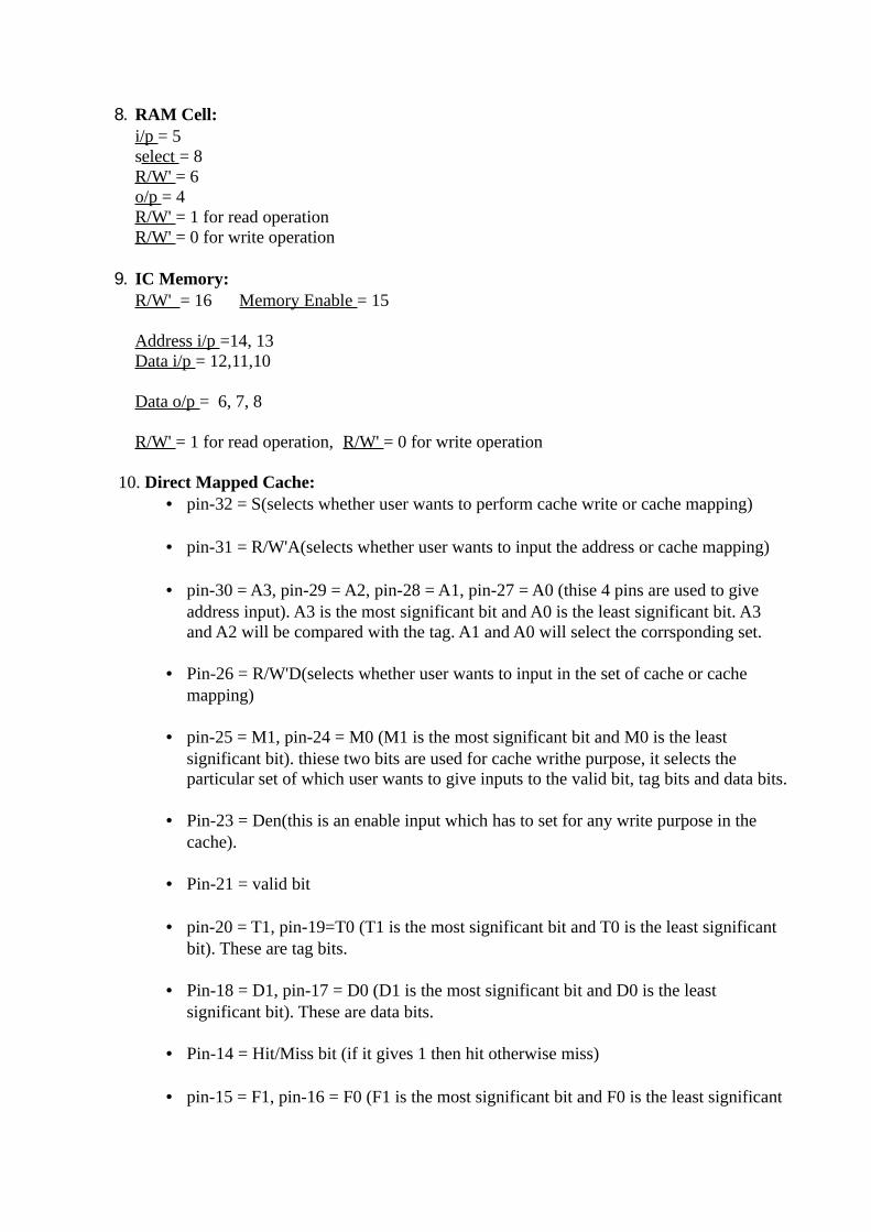
8. RAM Cell: i/p = 5select = 8R/W' = 6o/p = 4R/W' = 1 for read operationR/W' = 0 for write operation
9. IC Memory: R/W' = 16 Memory Enable = 15
Address i/p =14, 13Data i/p = 12,11,10
Data o/p = 6, 7, 8
R/W' = 1 for read operation, R/W' = 0 for write operation
10. Direct Mapped Cache: • pin-32 = S(selects whether user wants to perform cache write or cache mapping)
• pin-31 = R/W'A(selects whether user wants to input the address or cache mapping)
• pin-30 = A3, pin-29 = A2, pin-28 = A1, pin-27 = A0 (thise 4 pins are used to give address input). A3 is the most significant bit and A0 is the least significant bit. A3 and A2 will be compared with the tag. A1 and A0 will select the corrsponding set.
• Pin-26 = R/W'D(selects whether user wants to input in the set of cache or cache mapping)
• pin-25 = M1, pin-24 = M0 (M1 is the most significant bit and M0 is the least significant bit). thiese two bits are used for cache writhe purpose, it selects the particular set of which user wants to give inputs to the valid bit, tag bits and data bits.
• Pin-23 = Den(this is an enable input which has to set for any write purpose in the
cache).
• Pin-21 = valid bit
• pin-20 = T1, pin-19=T0 (T1 is the most significant bit and T0 is the least significant bit). These are tag bits.
• Pin-18 = D1, pin-17 = D0 (D1 is the most significant bit and D0 is the least significant bit). These are data bits.
• Pin-14 = Hit/Miss bit (if it gives 1 then hit otherwise miss)
• pin-15 = F1, pin-16 = F0 (F1 is the most significant bit and F0 is the least significant

bit). These are output data bits and will be given only when there is a hit.
• Essential pin configurations for writing in cache:S = 1, R/W'A = 0, R/W'D = 0, Den = 1
• Essential pin configurations for cache mapping:
S=0, R/W'A = 1, R/W'D = 1, Den = 0
12. Associative cache: Associative Cache (memory address 4 bit, 2 bit data)
• Upper Terminals:Inputs
• Bottom Terminals:Outputs
• Bottom Left Corner: Circle Represents pin-1
• Pin Numbering:Anticlockwise
• S = 32
• R/W'A = 31
• A3 = 30, A2 = 29, A1 = 28, A0 = 27
• R/W'D = 26
• M1 = 25, M0 = 24
• Den = 23
• V = 21, T1 = 20, T0 = 19, D1 = 18, D0 = 17
• o/p:
Hit/Miss bit = 14, F1 = 15, F0 = 16
• for cache write: S = 1, R/W'A = 0, R/W'D = 0, Den = 1
• for cache map: S = 0, R/W'A = 1, R/W'D = 1, Den = 0
• A3, A2, A1, A0 are memory address
• Convension followed: A3 = MSB, A0 = LSB
• M1, M0 selecting set for cache write
• v: valid bit
• T1, T0 are tag
• D1, D0 are input data
• F1, F0 are output data

• Computer design drawer:
1. CPU design: Create a single instruction CPU (central processing unit) with 13 input pins and 18 output pins.
• The instruction is subneg (SBN) which is 'subtract and branch if negative'
SBN a,b,c Mem[a] = Mem[a] – Mem[b]
if (Mem[a] < 0) then goto c
• This CPU contains a controller.The state chart for the controller has to be input from outside interface.
• input pin (upper) : data input = 20-31
clock input = 19
• output pin(lower) :
memory enable = 1
R/W' (read/write) = 2
address = 3-6
data output = 7-18
2. Memory: Create a memory with data bit: 12 and address bit:4• input pins = 18• output pins = 12• input ports(upper ports) :
• memory enable = 30• R/W' = 29• address = 25-28• data = 13-24
• output pins(lower) : 1-12 : data output