Embed Size (px)
Citation preview
Manual
The Zimbabwe Bush Pump
Installing and maintaining the “B” type Bush Pump
Peter Morgan 2009
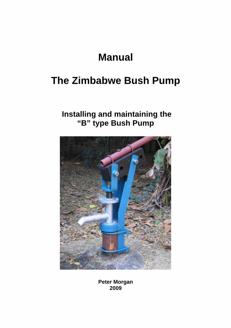
The Zimbabwe Bush Pump -an introduction The Bush Pump in one form or another has been used in Zimbabwe for over 70 years. All Bush Pumps are entirely Zimbabwean in origin and design and are regarded in Zimbabwe as National Treasures. No other hand pump on the African continent has provided such a prolonged service to its own people. The current National Standard Hand Pump is called the "B" type Bush Pump and was standardised by the Government of Zimbabwe in 1989 following rigorous trials in very heavy duty and deep borehole settings. The “B” type pump head is used with standard "down the hole" components, comprising 50mm nominal bore galvanised steel rising main, 16mm mild steel pump rods, a 75mm diameter brass cylinder operating with a piston fitted with two leather seals and a heavy duty brass foot valve. These components are well tested and durable if correctly made and installed. Currently there are about 40 000 Bush pump installed in the rural areas of Zimbabwe. Optimum performance of this unit can only be expected if the components are correctly manufactured and also correctly installed. The “B” type Bush Pump head is internationally recognised with international specifications and is regarded as a “Public Domain” pump. The precise specifications are available in hard copy (from SKAT Switzerland) and also appear on the internet. The unique feature of all Bush Pumps is its use of a hardwood bearing.
Parts of the pump head - general
Parts of the pump head
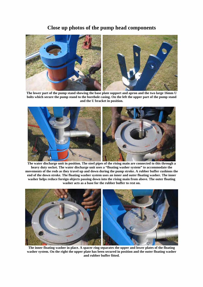
Close up photos of the pump head components
The lower part of the pump stand showing the base plate support and apron and the two large 16mm U bolts which secure the pump stand to the borehole casing. On the left the upper part of the pump stand
and the U bracket in position.
The water discharge unit in position. The steel pipes of the rising main are connected to this through a
heavy duty socket. The water discharge unit uses a “floating washer system” to accommodate the movements of the rods as they travel up and down during the pump stroke. A rubber buffer cushions the
end of the down stroke. The floating washer system uses an inner and outer floating washer. The inner washer helps reduce foreign objects passing down into the rising main from above. The outer floating
washer acts as a base for the rubber buffer to rest on.
The inner floating washer in place. A spacer ring separates the upper and lower plates of the floating
washer system. On the right the upper plate has been secured in position and the outer floating washer and rubber buffer fitted.
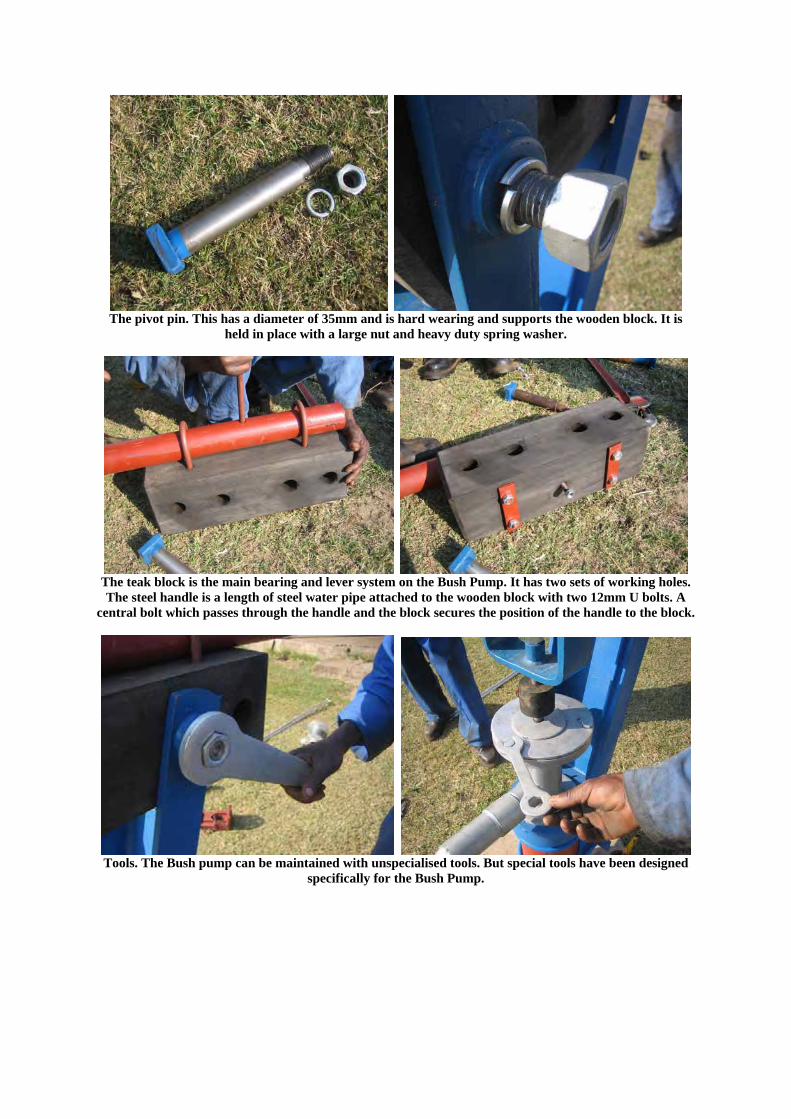
The pivot pin. This has a diameter of 35mm and is hard wearing and supports the wooden block. It is
held in place with a large nut and heavy duty spring washer.
The teak block is the main bearing and lever system on the Bush Pump. It has two sets of working holes. The steel handle is a length of steel water pipe attached to the wooden block with two 12mm U bolts. A
central bolt which passes through the handle and the block secures the position of the handle to the block.
Tools. The Bush pump can be maintained with unspecialised tools. But special tools have been designed
specifically for the Bush Pump.
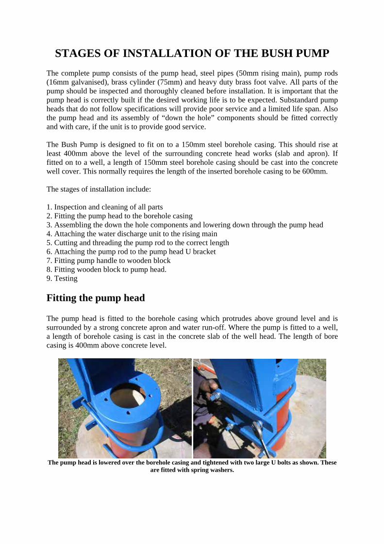
STAGES OF INSTALLATION OF THE BUSH PUMP
The complete pump consists of the pump head, steel pipes (50mm rising main), pump rods (16mm galvanised), brass cylinder (75mm) and heavy duty brass foot valve. All parts of the pump should be inspected and thoroughly cleaned before installation. It is important that the pump head is correctly built if the desired working life is to be expected. Substandard pump heads that do not follow specifications will provide poor service and a limited life span. Also the pump head and its assembly of “down the hole” components should be fitted correctly and with care, if the unit is to provide good service. The Bush Pump is designed to fit on to a 150mm steel borehole casing. This should rise at least 400mm above the level of the surrounding concrete head works (slab and apron). If fitted on to a well, a length of 150mm steel borehole casing should be cast into the concrete well cover. This normally requires the length of the inserted borehole casing to be 600mm. The stages of installation include: 1. Inspection and cleaning of all parts 2. Fitting the pump head to the borehole casing 3. Assembling the down the hole components and lowering down through the pump head 4. Attaching the water discharge unit to the rising main 5. Cutting and threading the pump rod to the correct length 6. Attaching the pump rod to the pump head U bracket 7. Fitting pump handle to wooden block 8. Fitting wooden block to pump head. 9. Testing Fitting the pump head
The pump head is fitted to the borehole casing which protrudes above ground level and is surrounded by a strong concrete apron and water run-off. Where the pump is fitted to a well, a length of borehole casing is cast in the concrete slab of the well head. The length of bore casing is 400mm above concrete level.
The pump head is lowered over the borehole casing and tightened with two large U bolts as shown. These
are fitted with spring washers.
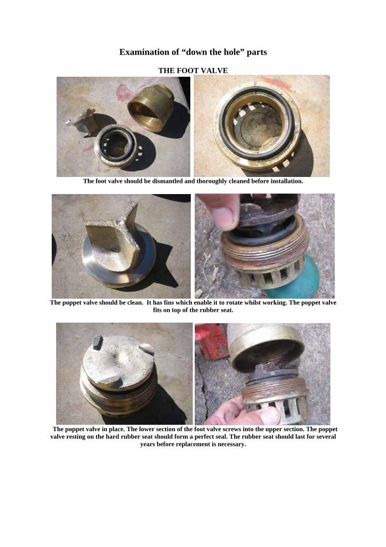
Examination of “down the hole” parts
THE FOOT VALVE
The foot valve should be dismantled and thoroughly cleaned before installation.
The poppet valve should be clean. It has fins which enable it to rotate whilst working. The poppet valve
fits on top of the rubber seat.
The poppet valve in place. The lower section of the foot valve screws into the upper section. The poppet valve resting on the hard rubber seat should form a perfect seal. The rubber seat should last for several
years before replacement is necessary.
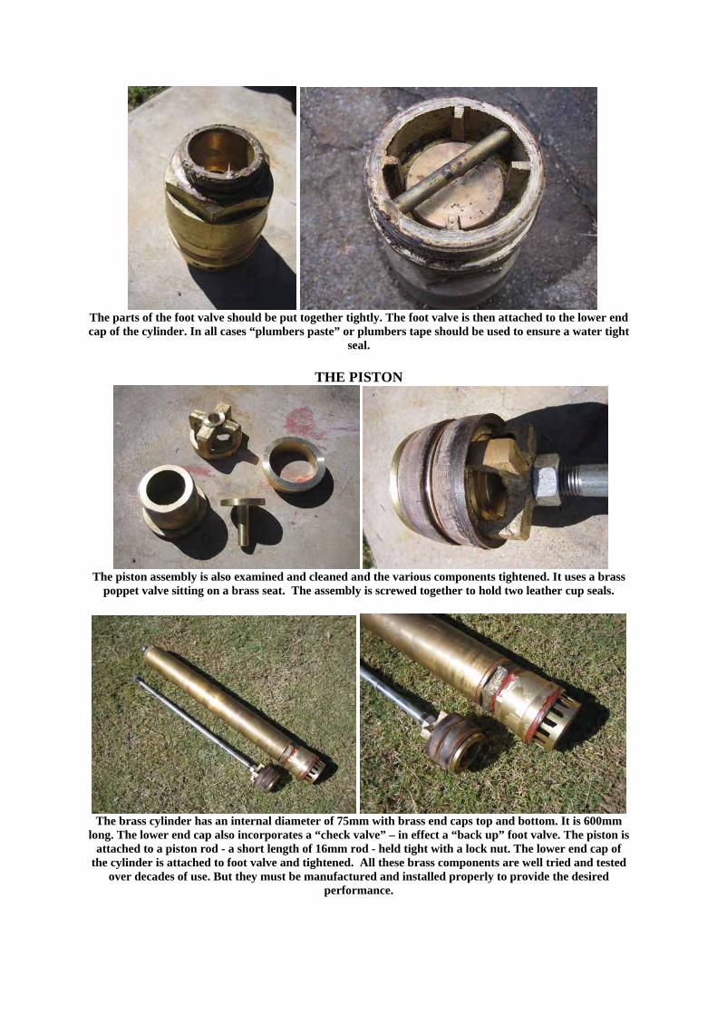
The parts of the foot valve should be put together tightly. The foot valve is then attached to the lower end cap of the cylinder. In all cases “plumbers paste” or plumbers tape should be used to ensure a water tight
seal.
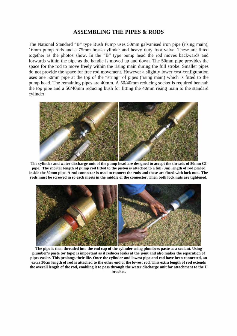
THE PISTON
The piston assembly is also examined and cleaned and the various components tightened. It uses a brass
poppet valve sitting on a brass seat. The assembly is screwed together to hold two leather cup seals.
The brass cylinder has an internal diameter of 75mm with brass end caps top and bottom. It is 600mm
long. The lower end cap also incorporates a “check valve” – in effect a “back up” foot valve. The piston is attached to a piston rod - a short length of 16mm rod - held tight with a lock nut. The lower end cap of
the cylinder is attached to foot valve and tightened. All these brass components are well tried and tested over decades of use. But they must be manufactured and installed properly to provide the desired
performance.
ASSEMBLING THE PIPES & RODS
The National Standard “B” type Bush Pump uses 50mm galvanised iron pipe (rising main), 16mm pump rods and a 75mm brass cylinder and heavy duty foot valve. These are fitted together as the photos show. In the “B” type pump head the rod moves backwards and forwards within the pipe as the handle is moved up and down. The 50mm pipe provides the space for the rod to move freely within the rising main during the full stroke. Smaller pipes do not provide the space for free rod movement. However a slightly lower cost configuration uses one 50mm pipe at the top of the “string” of pipes (rising main) which is fitted to the pump head. The remaining pipes are 40mm. A 50/40mm reducing socket is required beneath the top pipe and a 50/40mm reducing bush for fitting the 40mm rising main to the standard cylinder.
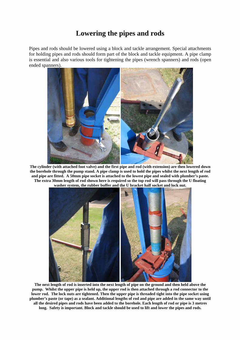
The cylinder and water discharge unit of the pump head are designed to accept the threads of 50mm GI pipe. The shorter length of pump rod fitted to the piston is attached to a full (3m) length of rod placed
inside the 50mm pipe. A rod connector is used to connect the rods and these are fitted with lock nuts. The rods must be screwed in so each meets in the middle of the connector. Then both lock nuts are tightened.
The pipe is then threaded into the end cap of the cylinder using plumbers paste as a sealant. Using
plumber’s paste (or tape) is important as it reduces leaks at the joint and also makes the separation of pipes easier. This prolongs their life. Once the cylinder and lowest pipe and rod have been connected, an extra 30cm length of rod is attached to the other end of the lowest rod. This extra length of rod extends
the overall length of the rod, enabling it to pass through the water discharge unit for attachment to the U bracket.
Lowering the pipes and rods
Pipes and rods should be lowered using a block and tackle arrangement. Special attachments for holding pipes and rods should form part of the block and tackle equipment. A pipe clamp is essential and also various tools for tightening the pipes (wrench spanners) and rods (open ended spanners).
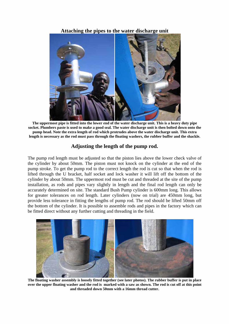
The cylinder (with attached foot valve) and the first pipe and rod (with extension) are then lowered down the borehole through the pump stand. A pipe clamp is used to hold the pipes whilst the next length of rod and pipe are fitted. A 50mm pipe socket is attached to the lowest pipe and sealed with plumber’s paste.
The extra 30mm length of rod shown here is required so the top rod will pass through the U floating washer system, the rubber buffer and the U bracket half socket and lock nut.
The next length of rod is inserted into the next length of pipe on the ground and then held above the
pump. Whilst the upper pipe is held up, the upper rod is then attached through a rod connector to the lower rod. The lock nuts are tightened. Then the upper pipe is threaded tight into the pipe socket using
plumber’s paste (or tape) as a sealant. Additional lengths of rod and pipe are added in the same way until all the desired pipes and rods have been added to the borehole. Each length of rod or pipe is 3 metres
long. Safety is important. Block and tackle should be used to lift and lower the pipes and rods.
Attaching the pipes to the water discharge unit
The uppermost pipe is fitted into the lower end of the water discharge unit. This is a heavy duty pipe
socket. Plumbers paste is used to make a good seal. The water discharge unit is then bolted down onto the pump head. Note the extra length of rod which protrudes above the water discharge unit. This extra
length is necessary as the rod must pass through the floating washers, the rubber buffer and the shackle.
Adjusting the length of the pump rod.
The pump rod length must be adjusted so that the piston lies above the lower check valve of the cylinder by about 50mm. The piston must not knock on the cylinder at the end of the pump stroke. To get the pump rod to the correct length the rod is cut so that when the rod is lifted through the U bracket, half socket and lock washer it will lift off the bottom of the cylinder by about 50mm. The uppermost rod must be cut and threaded at the site of the pump installation, as rods and pipes vary slightly in length and the final rod length can only be accurately determined on site. The standard Bush Pump cylinder is 600mm long. This allows for greater tolerances on rod length. Later cylinders (now on trial) are 450mm long, but provide less tolerance in fitting the lengths of pump rod. The rod should be lifted 50mm off the bottom of the cylinder. It is possible to assemble rods and pipes in the factory which can be fitted direct without any further cutting and threading in the field.
The floating washer assembly is loosely fitted together (see later photos). The rubber buffer is put in place over the upper floating washer and the rod is marked with a saw as shown. The rod is cut off at this point
and threaded down 50mm with a 16mm thread cutter.
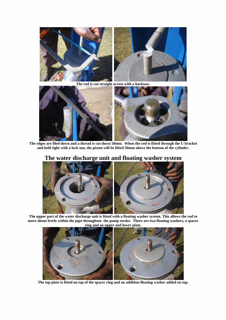
The rod is cut straight across with a hacksaw.
The edges are filed down and a thread is cut down 50mm. When the rod is fitted through the U bracket
and held tight with a lock nut, the piston will be lifted 50mm above the bottom of the cylinder.
The water discharge unit and floating washer system
The upper part of the water discharge unit is fitted with a floating washer system. This allows the rod to
move about freely within the pipe throughout the pump stroke. There are two floating washers, a spacer ring and an upper and lower plate.
The top plate is fitted on top of the spacer ring and an addition floating washer added on top.
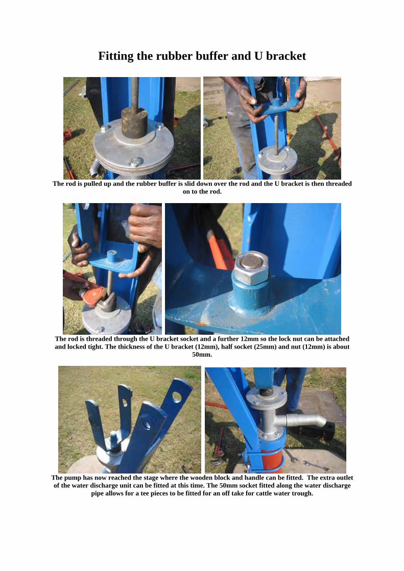
Fitting the rubber buffer and U bracket
The rod is pulled up and the rubber buffer is slid down over the rod and the U bracket is then threaded
on to the rod.
The rod is threaded through the U bracket socket and a further 12mm so the lock nut can be attached and locked tight. The thickness of the U bracket (12mm), half socket (25mm) and nut (12mm) is about
50mm.
The pump has now reached the stage where the wooden block and handle can be fitted. The extra outlet of the water discharge unit can be fitted at this time. The 50mm socket fitted along the water discharge
pipe allows for a tee pieces to be fitted for an off take for cattle water trough.
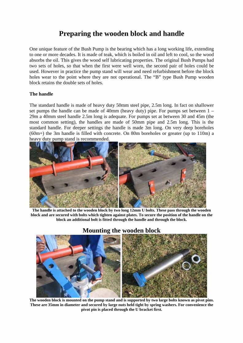
Preparing the wooden block and handle
One unique feature of the Bush Pump is the bearing which has a long working life, extending to one or more decades. It is made of teak, which is boiled in oil and left to cool, so the wood absorbs the oil. This gives the wood self lubricating properties. The original Bush Pumps had two sets of holes, so that when the first were well worn, the second pair of holes could be used. However in practice the pump stand will wear and need refurbishment before the block holes wear to the point where they are not operational. The “B” type Bush Pump wooden block retains the double sets of holes. The handle The standard handle is made of heavy duty 50mm steel pipe, 2.5m long. In fact on shallower set pumps the handle can be made of 40mm (heavy duty) pipe. For pumps set between 1 – 29m a 40mm steel handle 2.5m long is adequate. For pumps set at between 30 and 45m (the most common setting), the handles are made of 50mm pipe and 2.5m long. This is the standard handle. For deeper settings the handle is made 3m long. On very deep boreholes (60m+) the 3m handle is filled with concrete. On 80m boreholes or greater (up to 110m) a heavy duty pump stand is recommended.
The handle is attached to the wooden block by two long 12mm U bolts. These pass through the wooden
block and are secured with bolts which tighten against plates. To secure the position of the handle on the block an additional bolt is fitted through the handle and through the block.
Mounting the wooden block
The wooden block is mounted on the pump stand and is supported by two large bolts known as pivot pins. These are 35mm in diameter and secured by large nuts held tight by spring washers. For convenience the
pivot pin is placed through the U bracket first.
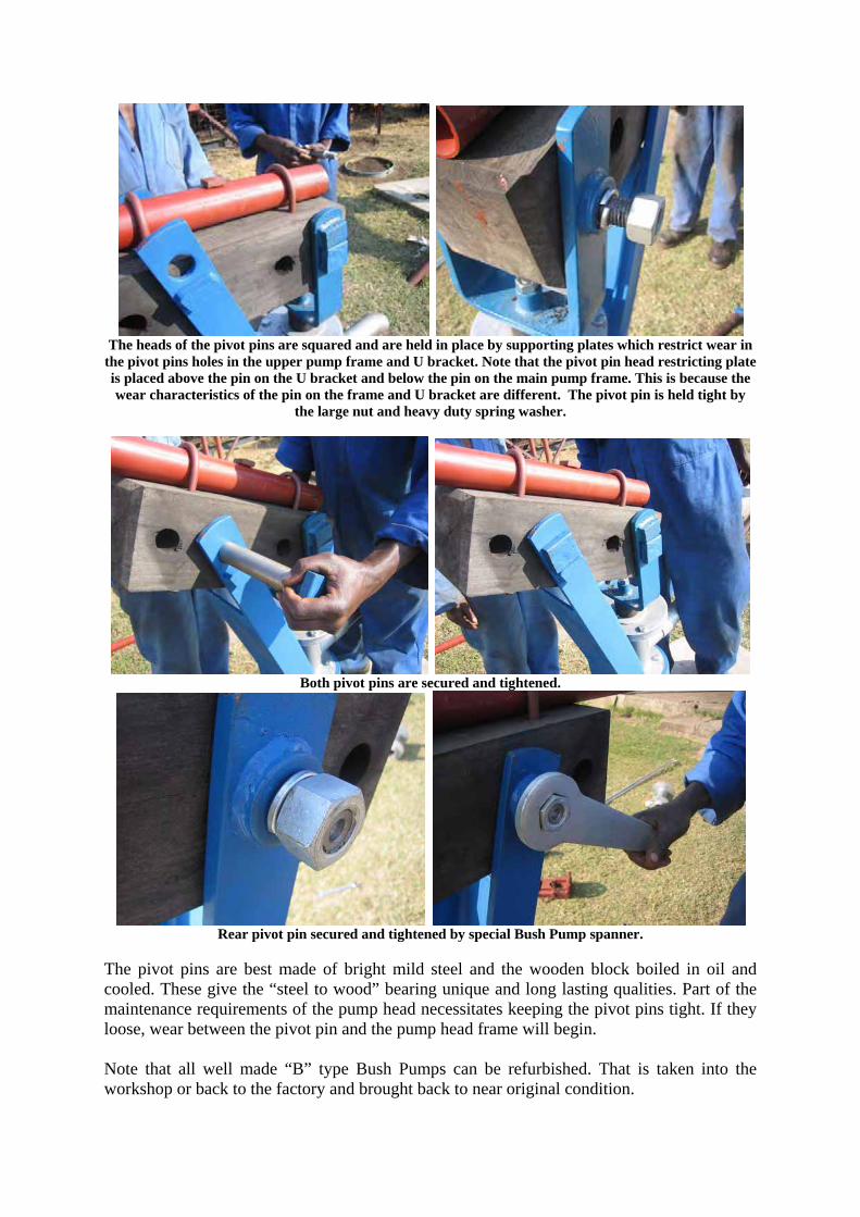
The heads of the pivot pins are squared and are held in place by supporting plates which restrict wear in
the pivot pins holes in the upper pump frame and U bracket. Note that the pivot pin head restricting plate is placed above the pin on the U bracket and below the pin on the main pump frame. This is because the wear characteristics of the pin on the frame and U bracket are different. The pivot pin is held tight by
the large nut and heavy duty spring washer.
Both pivot pins are secured and tightened.
Rear pivot pin secured and tightened by special Bush Pump spanner.
The pivot pins are best made of bright mild steel and the wooden block boiled in oil and cooled. These give the “steel to wood” bearing unique and long lasting qualities. Part of the maintenance requirements of the pump head necessitates keeping the pivot pins tight. If they loose, wear between the pivot pin and the pump head frame will begin. Note that all well made “B” type Bush Pumps can be refurbished. That is taken into the workshop or back to the factory and brought back to near original condition.
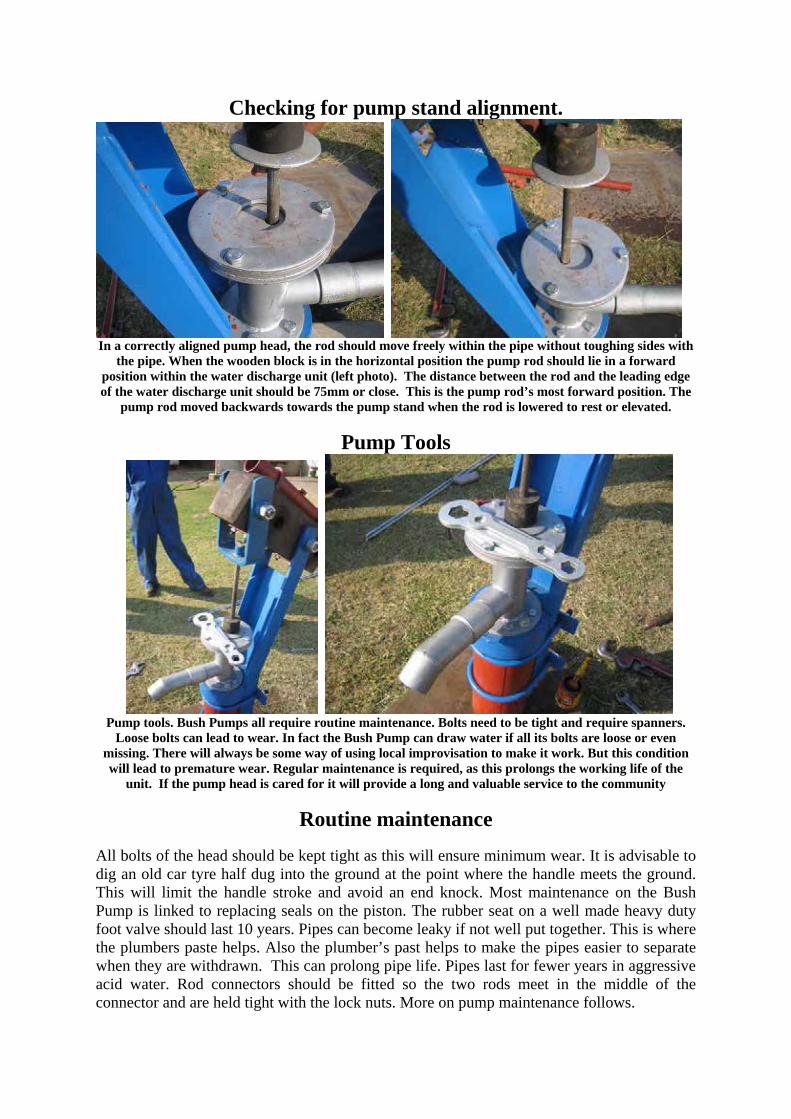
Checking for pump stand alignment.
In a correctly aligned pump head, the rod should move freely within the pipe without toughing sides with
the pipe. When the wooden block is in the horizontal position the pump rod should lie in a forward position within the water discharge unit (left photo). The distance between the rod and the leading edge of the water discharge unit should be 75mm or close. This is the pump rod’s most forward position. The
pump rod moved backwards towards the pump stand when the rod is lowered to rest or elevated.
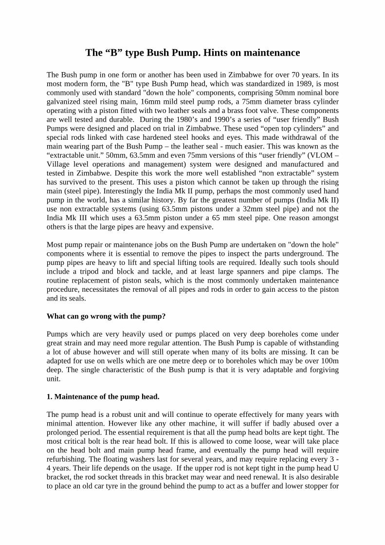
Pump Tools
Pump tools. Bush Pumps all require routine maintenance. Bolts need to be tight and require spanners.
Loose bolts can lead to wear. In fact the Bush Pump can draw water if all its bolts are loose or even missing. There will always be some way of using local improvisation to make it work. But this condition will lead to premature wear. Regular maintenance is required, as this prolongs the working life of the
unit. If the pump head is cared for it will provide a long and valuable service to the community
Routine maintenance
All bolts of the head should be kept tight as this will ensure minimum wear. It is advisable to dig an old car tyre half dug into the ground at the point where the handle meets the ground. This will limit the handle stroke and avoid an end knock. Most maintenance on the Bush Pump is linked to replacing seals on the piston. The rubber seat on a well made heavy duty foot valve should last 10 years. Pipes can become leaky if not well put together. This is where the plumbers paste helps. Also the plumber’s past helps to make the pipes easier to separate when they are withdrawn. This can prolong pipe life. Pipes last for fewer years in aggressive acid water. Rod connectors should be fitted so the two rods meet in the middle of the connector and are held tight with the lock nuts. More on pump maintenance follows.
The “B” type Bush Pump. Hints on maintenance The Bush pump in one form or another has been used in Zimbabwe for over 70 years. In its most modern form, the "B" type Bush Pump head, which was standardized in 1989, is most commonly used with standard "down the hole" components, comprising 50mm nominal bore galvanized steel rising main, 16mm mild steel pump rods, a 75mm diameter brass cylinder operating with a piston fitted with two leather seals and a brass foot valve. These components are well tested and durable. During the 1980’s and 1990’s a series of “user friendly” Bush Pumps were designed and placed on trial in Zimbabwe. These used “open top cylinders” and special rods linked with case hardened steel hooks and eyes. This made withdrawal of the main wearing part of the Bush Pump – the leather seal - much easier. This was known as the “extractable unit.” 50mm, 63.5mm and even 75mm versions of this “user friendly” (VLOM – Village level operations and management) system were designed and manufactured and tested in Zimbabwe. Despite this work the more well established “non extractable” system has survived to the present. This uses a piston which cannot be taken up through the rising main (steel pipe). Interestingly the India Mk II pump, perhaps the most commonly used hand pump in the world, has a similar history. By far the greatest number of pumps (India Mk II) use non extractable systems (using 63.5mm pistons under a 32mm steel pipe) and not the India Mk III which uses a 63.5mm piston under a 65 mm steel pipe. One reason amongst others is that the large pipes are heavy and expensive. Most pump repair or maintenance jobs on the Bush Pump are undertaken on "down the hole" components where it is essential to remove the pipes to inspect the parts underground. The pump pipes are heavy to lift and special lifting tools are required. Ideally such tools should include a tripod and block and tackle, and at least large spanners and pipe clamps. The routine replacement of piston seals, which is the most commonly undertaken maintenance procedure, necessitates the removal of all pipes and rods in order to gain access to the piston and its seals. What can go wrong with the pump? Pumps which are very heavily used or pumps placed on very deep boreholes come under great strain and may need more regular attention. The Bush Pump is capable of withstanding a lot of abuse however and will still operate when many of its bolts are missing. It can be adapted for use on wells which are one metre deep or to boreholes which may be over 100m deep. The single characteristic of the Bush pump is that it is very adaptable and forgiving unit. 1. Maintenance of the pump head. The pump head is a robust unit and will continue to operate effectively for many years with minimal attention. However like any other machine, it will suffer if badly abused over a prolonged period. The essential requirement is that all the pump head bolts are kept tight. The most critical bolt is the rear head bolt. If this is allowed to come loose, wear will take place on the head bolt and main pump head frame, and eventually the pump head will require refurbishing. The floating washers last for several years, and may require replacing every 3 - 4 years. Their life depends on the usage. If the upper rod is not kept tight in the pump head U bracket, the rod socket threads in this bracket may wear and need renewal. It is also desirable to place an old car tyre in the ground behind the pump to act as a buffer and lower stopper for
the handle. The rubber buffer placed on top of the floating washers may also need replacing after some years. There are few other wearing parts. The wooden block should last for at least a decade or two. For the pump head the answer is to keep all bolts tight - and spanners are essential for this purpose. Special spanners have been designed. 2. Down the hole components Most of the maintenance of the Bush Pump is concerned with parts which lie below ground level. Maintenance and repair of “down the hole” parts include: 1. Replacement of leather seals 2. Attention to faulty or worn or leaky rising mains 3. Attention to faulty or worn pump rods 4. Attention to leaky foot valves 5. Attention to faulty piston valves 6. Attention to faulty or worn cylinders Many problems occur because the parts are poorly made in the first place. Defective pipes, rods, cylinders, piston valves and foot valves are not uncommon. Shoddy work in the factory will inevitably lead to repeated problems in the field. Also problems occur when the pump is poorly installed. Many problems occur because the parts are simply not put together properly. Also problems occur because the parts are not properly inspected, cleaned and fitted together carefully and tightly. The pipe threads should always be cleaned and plumbers paste or tape should be used on the threaded joints. When the paste is used the pipes are better sealed against leakage and also easier to separate when the pump is dismantled. This extends the life of the pipes. 2a. Replacement of piston seals. Piston seals used in Zimbabwe are made of leather and this forms an excellent material for the piston seal. The leather is able to absorb small particles of grit etc which rubber or plastic seals may have difficulty in coping with. The twin leather seals of the 75mm piston may last for 1-3 years or even longer depending on quality of the seal, working conditions and quality of the water. Seal life is also influenced by the quality of the cylinder, specifically the smoothness of the internal cylinder surface. Seals should be replaced by new seals of the highest possible quality. Replacing seals with partly worn or poor quality units will increase the overall cost of maintenance. Leather is a unique manufactured product made by tanning through a chemical process to preserve the hide permanently, whilst at the same time retaining the natural fibrous structure from which leather’s ultimate strength and pliability are derived. During the manufacture of high quality leather seals the leather is impregnated with oils which fill the fibres and yet still allow the water to be absorbed into the microscopic spaces between the fibres. Thus the seal remains flexible for the whole of its life unless it dries out. Leather absorbs and takes in small particles of sand and grit and so preserves the smooth finish of a well made cylinder bore. When fitting new seals always check the whole cylinder. See if the check valve within the cylinder is jammed. Also check the piston itself. The piston valve (poppet) should move freely and make a good seal on the valve seat. Discard old leather seals (cups). After the new seal is fitted tighten up all the components of the piston assembly. Make sure the lock nut is tight on the rod which enters the piston head. Clean all the parts of piston and cylinder. It is
wise to check the cylinder assembly and the foot valve in a bucket of water before it goes down the hole. The foot valve must hold water – no leaks. Cleanliness of these parts is essential. If a bit of grit or other small object is jammed between the poppet valve and seat (of the piston or foot valve), the system will become leaky and not so efficient. 2b. Attention to steel pipes These are expensive components. Pipes last longer in softer water (where the pH is about neutral) and their life is reduced as a result of corrosion in more aggressive, acid water. There is much variation in the quality of water being extracted even within a single district. Where the water is more aggressive, the pipes turn brown with rust, and holes may develop at weak points in the assembly of the pipe (i.e. down the weld line). In general pipes can be expected to last for 10 years. Several factors influence the life of the pipes (rising main). Pipes vary greatly in quality and thickness. Obviously the best pipes give the longest service. Thin walled and poor quality pipes may look similar to strong thick walled pipes, but in every other way they are not. Choose good quality pipes for longer life. Sometimes a hole develops in the welded seam of the pipe. However most pipes deteriorate at the joints where they are threaded. The threads are particularly vulnerable to corrosion as the galvanised protective surface is removed. This is also the part which suffers the most damage during dismantling and assembly of the pump. These problems can be largely (although not completely) overcome by using plumbers paste in the joints. The paste helps to protect the exposed steel and also makes separation of the pipes easier when they are lifted. This alone will extend the working life of the pipe. Pipe life is reduced as a result of constant removal and reassembly. Rough handling also reduces pipe life, where pipes and their threads may becomes dented or damaged in other ways. Where piston seal life is longer (due to cleaner water, smoothed walled cylinders of high quality seals), the pipes require removal less frequently and last longer. Thus the best conditions occur when high quality seals are used and where the water is clear and does not contain fine silts. Clarified well water is ideal, but most Bush Pumps work on boreholes. Properly developed boreholes should yield water of high physical quality. But many may not reach this standard. Also boreholes which are not drilled vertically can cause excessive wear on pipes and rods and pumps installed on these poorly made boreholes can suffer a lot of punishment. A good pump on a well drilled and lined borehole is the best combination. Such damage or wear on pipes is much reduced if the pipe is rarely touched. Evidence for this can be seen in the life of pipes used in the mono pump which is driven by an electric or diesel pump fitted at the head. Once properly installed the “down the hole” components are rarely lifted. In this case the pipes may last for up to 15 or 20 years. Just to repeat, the easiest way of extending pipe life is to use plumbers paste (Plumber’s Delight) in the threading when joining pipes. This makes a good seal and helps to reduce corrosion. Its use thus lengthens the life of the pipe. All pipe joints should be done up tightly to reduce leaks. 2c) Pump rods The most common problem with pump rods is separation at the joints. This is often due to loosened or worn threads on the rods and rod sockets (connectors). 16mm mild steel rods
usually last for at least 5 years and up to 10 years. Once again the weakest part is the threaded end. Rod separation in conventional components can result from erosion of the thread behind the lock nut. Once the lock nut is loose the main rod socket can unscrew and rod separation results. Simultaneously the threads of the rod are spoilt. New threads cannot easily be made on older rods, where the diameter is being reduced. Consequently old rods, which may have sufficient strength, but not enough diameter for threading are thrown away. In the case where they are rethreaded because budgets do not allow for replacement by new parts, the number of breakdowns due to rod failure increases further. Rods may also crack, most commonly in the threaded section. This is normally due to excessive strain on the parts, due to great depths or defective rods. 16mm rods are much sturdier and last much longer than 12mm rods and have been used as the national standard for many years. It is obviously important to ensure that all the joints are done up tightly and that each rod occupies half the socket. If the rod is only partly screwed into the socket, the joint will separate earlier. It is also important to ensure that the rod joints and the pipe joints do not meet at the same point as this will lead to unnecessary friction and wear. 2d) Foot valve If the foot valve leaks, the pump will produce less water per stroke and will require some priming on every occasion it is used. This may take some time especially on deeper boreholes. This extra pumping can place extra and unnecessary strain on the pump head as well as the users. It is essential to choose a good foot valve in the first place. The standard heavy duty foot valve has always been recommended for use in Zimbabwe. It is a thoroughly tested and well established unit and gives reliable service then properly manufactured and installed. This foot valve is a “masterpiece of design” and far outranks just about all other foot valves. Poor quality foot valves should not be used on the Bush Pump. They may cost less but the ultimate cost of increased maintenance is far greater. The foot valve should always be dismantled, inspected and cleaned before use, even when new. Check that the rubber seat and the brass valve make a good seal. Do not use faulty units. They should be sent back to the manufacturers. Screw the unit up tightly. A hard rubber seal fitted in a slot should make the unit water tight under the brass poppet valve. The brass valve has fins which make the unit turn during use, thus providing even wear. This rubber seal may take up to ten years to wear down. This unit is reliable and rarely needs attention. It is important to check the foot valve thoroughly before final assembly. The standard Zimbabwe cylinder also has a foot valve in its base known as a check valve. This serves as a second back up unit to hold water up in the rising main. When one considers that some pumps in Zimbabwe pump up water from the height of the Victoria Falls, then one sees why a back up valve may be desirable. 2e). Piston assembly Usually the piston fails because the seals are worn or other parts of the unit unscrew and fall apart. The piston unit itself may unscrew and separate from the rod. The lock nut used to secure the piston unit to the rod should be done up tightly. Occasionally the valve (poppet) itself may fail or become jammed. This is mainly due to faulty manufacture or fitting. Use good seals and tighten up all parts of the unit correctly 2f). Cylinder Cylinders should rarely give trouble if properly made and installed. Sometimes cylinders leak because the end caps have been screwed up with too much force. The unit is made of brass

which is a relatively soft metal. Care is required. The end caps should be done up tightly, but not with excessive force which may result in the cracking of the end of the cylinder. Note the cylinder is made of soft brass and should always be handled with care and never held in a vice or pipe wrench. The end caps should be used to attach spanners whilst the rising main and foot valves are fitted. Cylinders wear out more quickly if the water is silted or carries grit or sand. Properly drilled and developed boreholes and dug wells should provide water with a good physical quality. The foot valve should not be too close to the base of a well. Half a meter is a minimum. Conclusions Choose well made pumps which are built according to specifications. Check on the pumps. An inspection chart is available. Choose well made “down the hole” components. Poorly made pumps do not last – they are an insult to the people they were designed to serve. Also the pump must be installed correctly and carefully if it is to provide a long and reliable service to the community. Fetching water from the borehole is an important part of rural life as the following photo shows.
The Bush Pump is a National Treasure. It has been honoured on a postage stamp!