Embed Size (px)
Citation preview
ULTRASONIC
LEVEL METER
101DP-SERIES
MANUAL
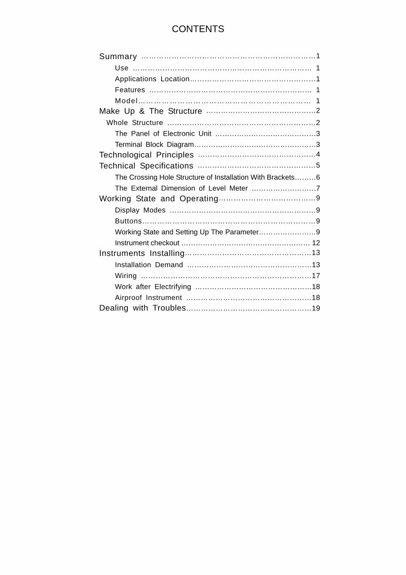
CONTENTS
Summary ……………………………………………………………1
Use ……………………………………………………………… 1
Applications Location……………………………………………1
Features ………………………………………………………… 1
Model………………………………………………………… 1
Make Up & The Structure ………………………………………2
Whole Structure ……………………………………………………2
The Panel of Electronic Unit ……………………………………3
Terminal Block Diagram……………………………………………3
Technological Principles …………………………………………4
Technical Specifications …………………………………………5
The Crossing Hole Structure of Installation With Brackets………6
The External Dimension of Level Meter ………………………7
Working State and Operating…………………………………9
Display Modes ……………………………………………………9
Buttons……………………………………………………………9
Working State and Setting Up The Parameter……………………9
Instrument checkout ……………………………………………… 12
Instruments Installing……………………………………………13
Installation Demand ……………………………………………13
Wiring ……………………………………………………………17
Work after Electrifying …………………………………………18
Airproof Instrument ……………………………………………18
Dealing with Troubles……………………………………………19
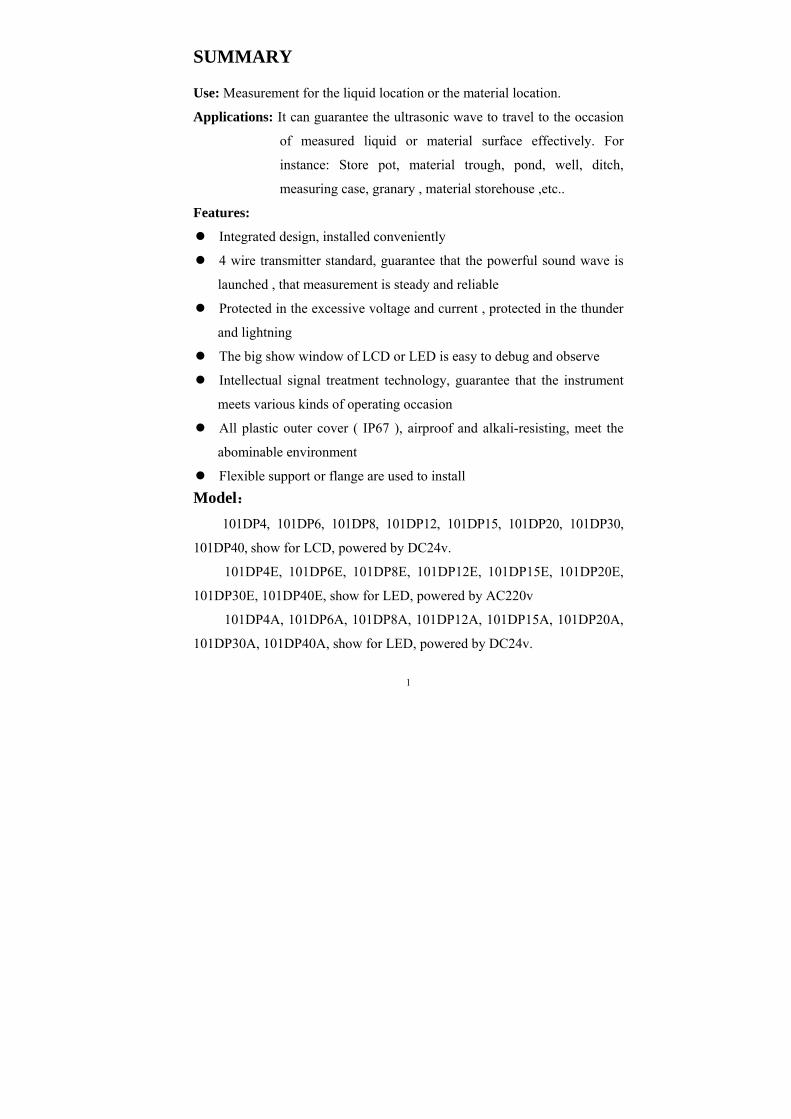
SUMMARY
Use: Measurement for the liquid location or the material location.
Applications: It can guarantee the ultrasonic wave to travel to the occasion
of measured liquid or material surface effectively. For
instance: Store pot, material trough, pond, well, ditch,
measuring case, granary , material storehouse ,etc..
Features:
Integrated design, installed conveniently
4 wire transmitter standard, guarantee that the powerful sound wave is
launched , that measurement is steady and reliable
Protected in the excessive voltage and current , protected in the thunder
and lightning
The big show window of LCD or LED is easy to debug and observe
Intellectual signal treatment technology, guarantee that the instrument
meets various kinds of operating occasion
All plastic outer cover ( IP67 ), airproof and alkali-resisting, meet the
abominable environment
Flexible support or flange are used to install
Model:
101DP4, 101DP6, 101DP8, 101DP12, 101DP15, 101DP20, 101DP30,
101DP40, show for LCD, powered by DC24v.
101DP4E, 101DP6E, 101DP8E, 101DP12E, 101DP15E, 101DP20E,
101DP30E, 101DP40E, show for LED, powered by AC220v
101DP4A, 101DP6A, 101DP8A, 101DP12A, 101DP15A, 101DP20A,
101DP30A, 101DP40A, show for LED, powered by DC24v.
1
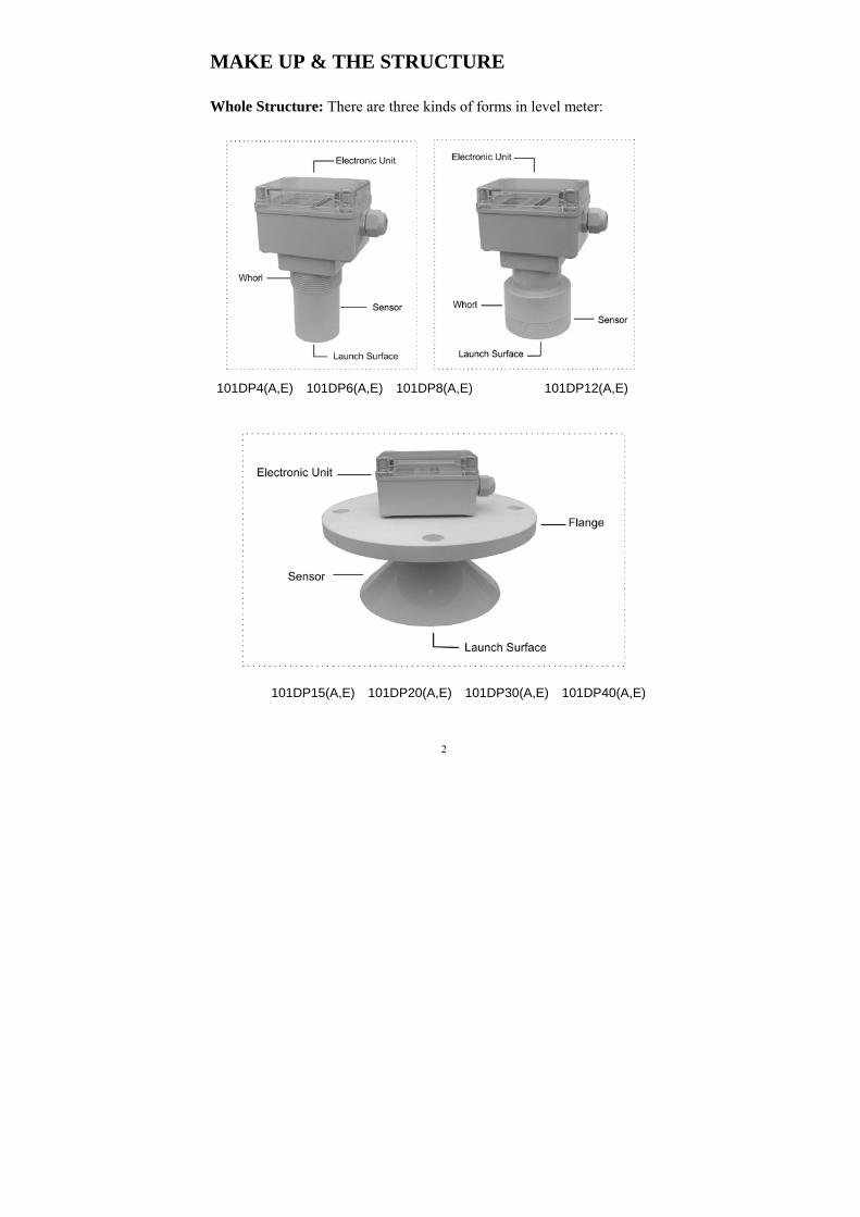
MAKE UP & THE STRUCTURE
Whole Structure: There are three kinds of forms in level meter:
101DP4(A,E) 101DP6(A,E) 101DP8(A,E) 101DP12(A,E)
101DP15(A,E) 101DP20(A,E) 101DP30(A,E) 101DP40(A,E)
2
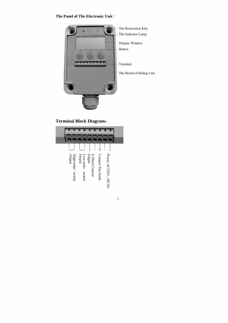
The Panel of The Electronic Unit:
Terminal Block Diagram:
3
The Restoration key
The Indicator Lamp
Display Window
Terminal
Button
The Board of Hiding Line
Pow
er AC
220V , D
C24v
Connect T
he Earth
4-20mA
Current
Output
Low
-ordersw
itchO
utput
High-order
switch
Output
TECHNOLOGICAL PRINCIPLE
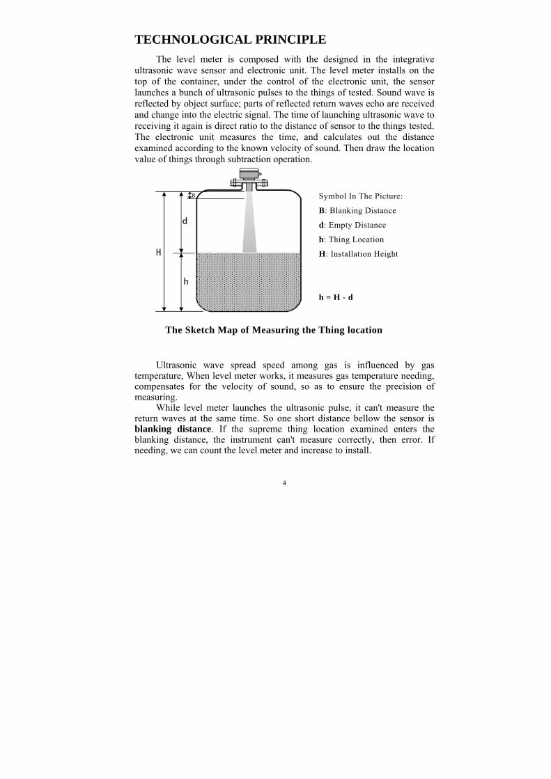
The level meter is composed with the designed in the integrative ultrasonic wave sensor and electronic unit. The level meter installs on the top of the container, under the control of the electronic unit, the sensor launches a bunch of ultrasonic pulses to the things of tested. Sound wave is reflected by object surface; parts of reflected return waves echo are received and change into the electric signal. The time of launching ultrasonic wave to receiving it again is direct ratio to the distance of sensor to the things tested. The electronic unit measures the time, and calculates out the distance examined according to the known velocity of sound. Then draw the location value of things through subtraction operation.
Ultrasonic wave spread speed among gas is influenced by gas
temperature, When level meter works, it measures gas temperature needing, compensates for the velocity of sound, so as to ensure the precision of measuring.
While level meter launches the ultrasonic pulse, it can't measure the return waves at the same time. So one short distance bellow the sensor is blanking distance. If the supreme thing location examined enters the blanking distance, the instrument can't measure correctly, then error. If needing, we can count the level meter and increase to install.
4
Symbol In The Picture:
B: Blanking Distance
d: Empty Distance
h: Thing Location
H: Installation Height
h = H - d
The Sketch Map of Measuring the Thing location
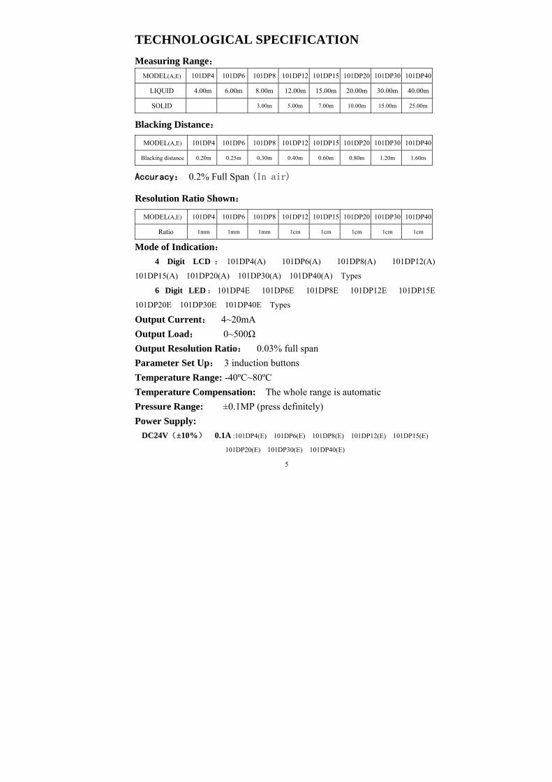
TECHNOLOGICAL SPECIFICATION
Measuring Range:
MODEL(A,E) 101DP4 101DP6 101DP8 101DP12 101DP15 101DP20 101DP30 101DP40
LIQUID 4.00m 6.00m 8.00m 12.00m 15.00m 20.00m 30.00m 40.00m
SOLID 3.00m 5.00m 7.00m 10.00m 15.00m 25.00m
Blacking Distance:
MODEL(A,E) 101DP4 101DP6 101DP8 101DP12 101DP15 101DP20 101DP30 101DP40
Blacking distance 0.20m 0.25m 0.30m 0.40m 0.60m 0.80m 1.20m 1.60m
Accuracy: 0.2% Full Span (In air)
Resolution Ratio Shown:
MODEL(A,E) 101DP4 101DP6 101DP8 101DP12 101DP15 101DP20 101DP30 101DP40
Ratio 1mm 1mm 1mm 1cm 1cm 1cm 1cm 1cm
Mode of Indication:
4 Digit LCD : 101DP4(A) 101DP6(A) 101DP8(A) 101DP12(A)
101DP15(A) 101DP20(A) 101DP30(A) 101DP40(A) Types
6 Digit LED : 101DP4E 101DP6E 101DP8E 101DP12E 101DP15E
101DP20E 101DP30E 101DP40E Types
Output Current: 4~20mA
Output Load: 0~500Ω
Output Resolution Ratio: 0.03% full span
Parameter Set Up: 3 induction buttons
Temperature Range: -40ºC~80ºC
Temperature Compensation: The whole range is automatic
Pressure Range: ±0.1MP (press definitely)
Power Supply:
DC24V(±10%) 0.1A :101DP4(E) 101DP6(E) 101DP8(E) 101DP12(E) 101DP15(E)
101DP20(E) 101DP30(E) 101DP40(E)
5
AC220v(±10%) 0.05A: 101DP4A 101DP6A 101DP8A 101DP12A 101DP15A
101DP20A 101DP30A 101DP40A
Cable Diameter: 6~12mm
Single Wire Diameter: 0.5~1.78mm
Cable Fix: PG13.5
Beam Angle: 8º(3db) –(101DP4, 101DP6, 101DP8)
5º(3db)-- (101DP12, 101DP15, 101DP20, 101DP30, 101DP40)
Measure Cycle: 1second
Crust Material: ABS
Sensor Material: PVC
Protect Grade: IP67
Mode Installation: Flange or the support
Flange Standard of Butt Joint:
Measuring range 4m 6m 8m:Minimum DN65
Measuring range 12m:Minimum DN80
Measuring range 15m:Minimum DN150
Measuring range 15m 20m 30m 40m:Minimum DN200
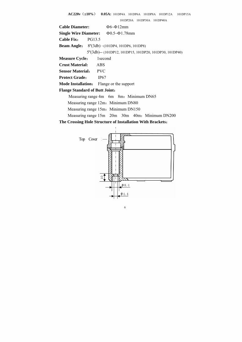
The Crossing Hole Structure of Installation With Brackets:
6
Top Cover
Should open the top cover while installing, then penetrate M4 regular
screw or the bolt downwards.
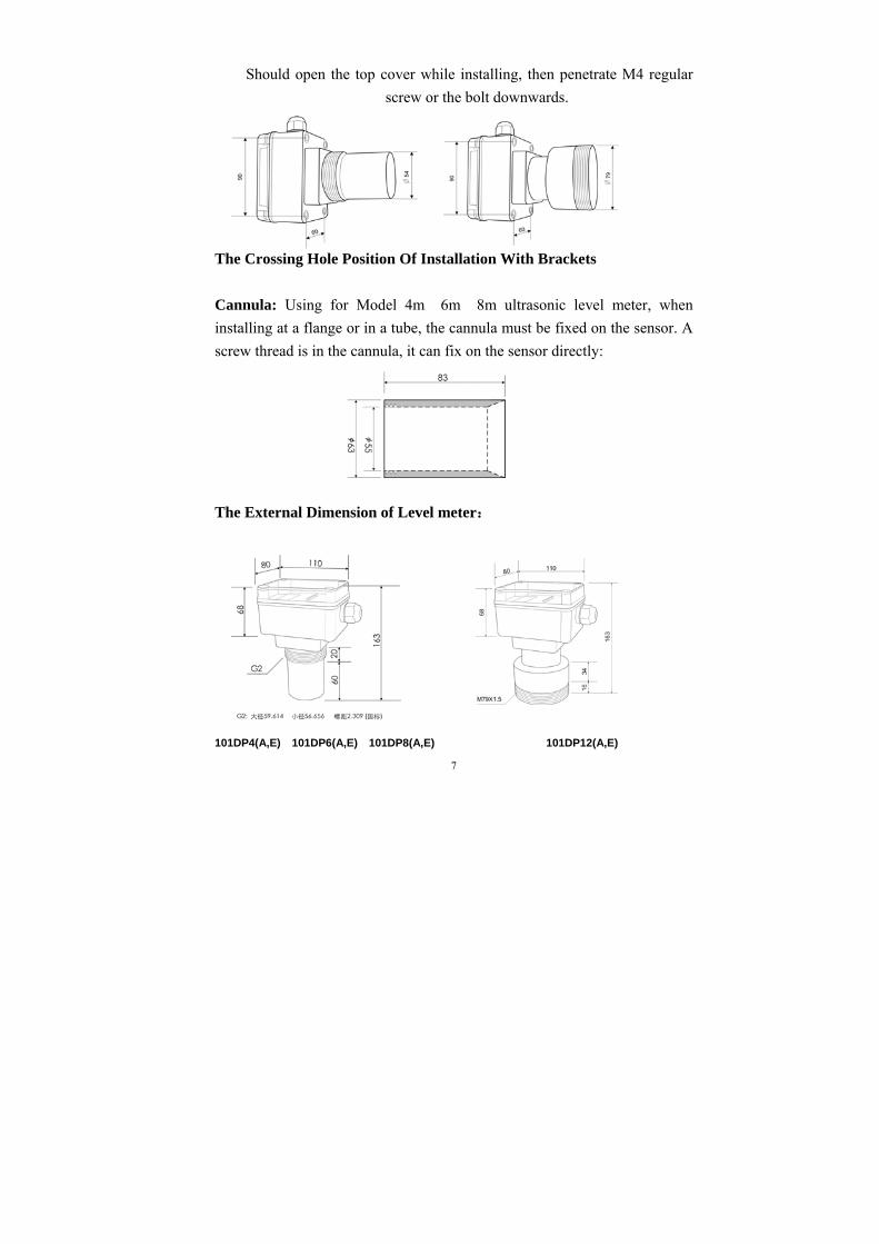
The Crossing Hole Position Of Installation With Brackets
Cannula: Using for Model 4m 6m 8m ultrasonic level meter, when
installing at a flange or in a tube, the cannula must be fixed on the sensor. A
screw thread is in the cannula, it can fix on the sensor directly:
The External Dimension of Level meter:
101DP4(A,E) 101DP6(A,E) 101DP8(A,E) 101DP12(A,E)
7
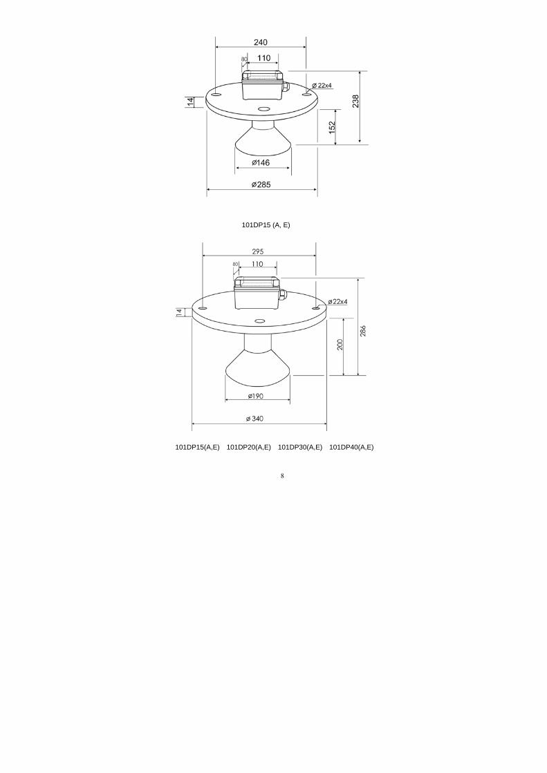
101DP15 (A, E)
101DP15(A,E) 101DP20(A,E) 101DP30(A,E) 101DP40(A,E)
8
INSTRUMENT OF WORKING STATION AND OPRATION
Display Modes
4 digit LCD liquid crystal display
Buttons
There are 4 keys on the instrument, the function as follows:
SEL: For choosing different display content or parameter.
INC: When setting up the parameter input a certain digit figure from
0 to 9 circulation change.
MOV: Choose a certain digit while setting up the parameter. When
choosing this digit, this digit becomes dark, later pressed INC key and
revised its value.
R: Press this key, the instrument is restored.
Working State and Setting up the Parameter
The instrument has two kinds of working state:
Measure state & State of setting up the parameter
Pressing SEL、MOV key at the same time can be switched around.
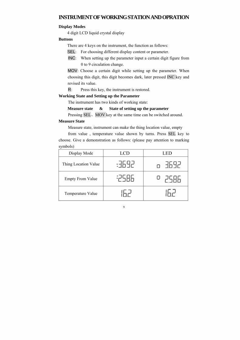
Measure State
Measure state, instrument can make the thing location value, empty
from value , temperature value shown by turns. Press SEL key to
choose. Give a demonstration as follows: (please pay attention to marking
symbols)
Display Mode LCD LED
Thing Location Value
Empty From Value
Temperature Value
9
No matter what kinds of number value it will be shown, the current
outputting of instrument is always the corresponding thing location value.
There is one getting green indicator lamp in the top of the
instrument panel, once one second, indicate that having echo to be
admitted arriving at the unit of the thing location value and the empty from
value is meter(m ), the unit of temperature is degrees Centigrade.
Pressing SEL and MOV keys at the same time, instrument can enter
the state of the setting up parameters.
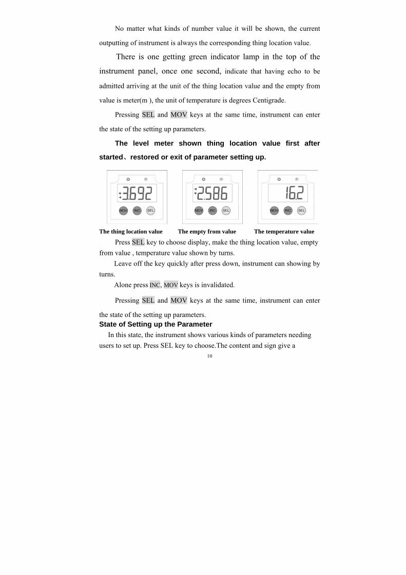
The level meter shown thing location value first after
started、restored or exit of parameter setting up.
The thing location value The empty from value The temperature value
Press SEL key to choose display, make the thing location value, empty
from value , temperature value shown by turns.
Leave off the key quickly after press down, instrument can showing by
turns.
Alone press INC, MOV keys is invalidated.
Pressing SEL and MOV keys at the same time, instrument can enter
the state of the setting up parameters. State of Setting up the Parameter
In this state, the instrument shows various kinds of parameters needing
users to set up. Press SEL key to choose.The content and sign give a 10
demonstration as follows:
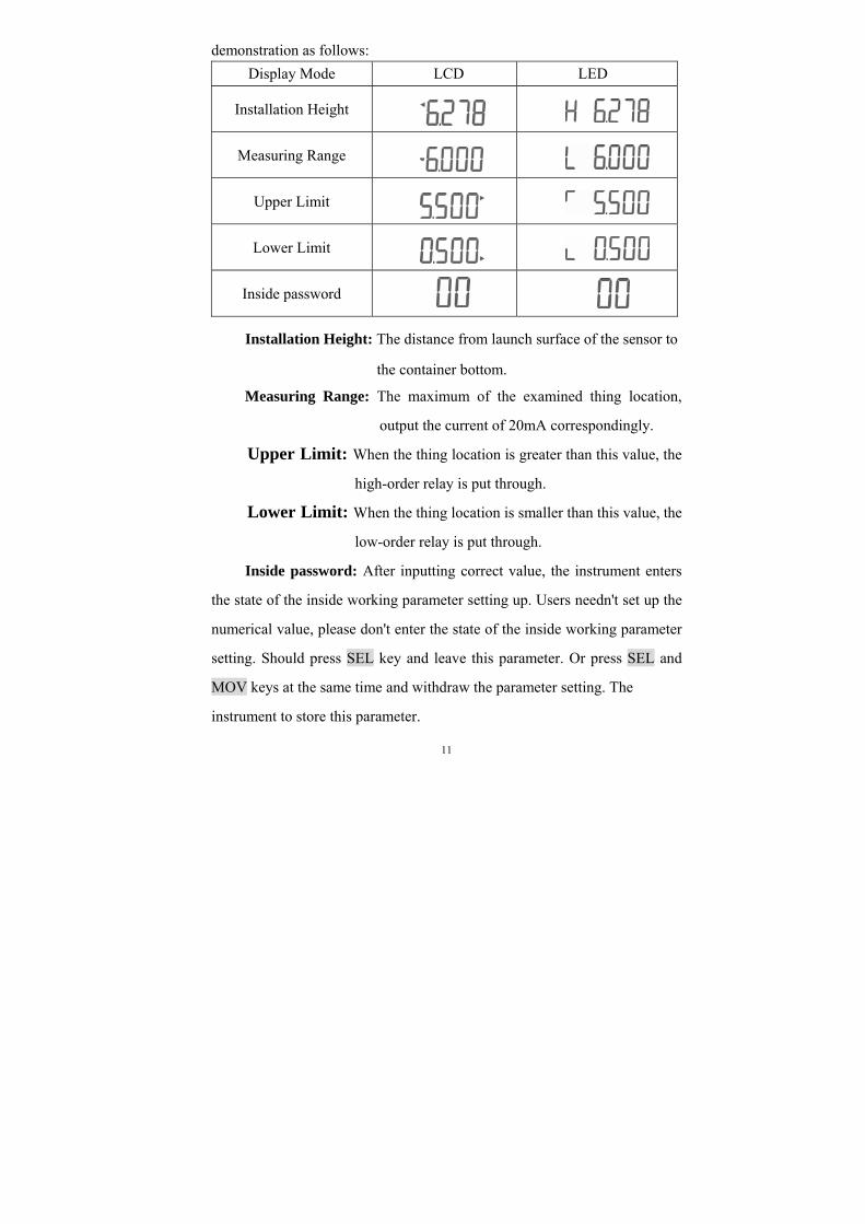
Display Mode LCD LED
Installation Height
Measuring Range
Upper Limit
Lower Limit
Inside password
Installation Height: The distance from launch surface of the sensor to
the container bottom.
Measuring Range: The maximum of the examined thing location,
output the current of 20mA correspondingly.
Upper Limit: When the thing location is greater than this value, the
high-order relay is put through.
Lower Limit: When the thing location is smaller than this value, the
low-order relay is put through.
Inside password: After inputting correct value, the instrument enters
the state of the inside working parameter setting up. Users needn't set up the
numerical value, please don't enter the state of the inside working parameter
setting. Should press SEL key and leave this parameter. Or press SEL and
MOV keys at the same time and withdraw the parameter setting. The
instrument to store this parameter.
11
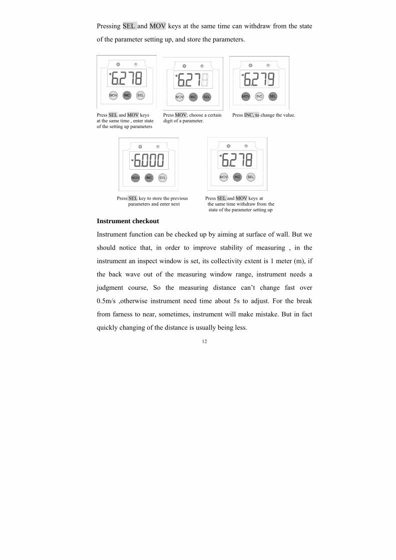
Pressing SEL and MOV keys at the same time can withdraw from the state
of the parameter setting up, and store the parameters.
Press SEL and MOV keys Press MOV; choose a certain Press INC, to change the value. at the same time , enter state digit of a parameter. of the setting up parameters
Press SEL key to store the previous Press SEL and MOV keys at parameters and enter next the same time withdraw from the state of the parameter setting up
Instrument checkout
Instrument function can be checked up by aiming at surface of wall. But we
should notice that, in order to improve stability of measuring , in the
instrument an inspect window is set, its collectivity extent is 1 meter (m), if
the back wave out of the measuring window range, instrument needs a
judgment course, So the measuring distance can’t change fast over
0.5m/s ,otherwise instrument need time about 5s to adjust. For the break
from farness to near, sometimes, instrument will make mistake. But in fact
quickly changing of the distance is usually being less.
12
INSTRUMENT INSTALLING
The rational installation of the instrument is the key to working
reliably.
The instrument install above container, launch surface of the sensor
should point to the liquid surface or the material surface vertically. If it is the
airtight container, should adopt the flange type to install. Other situations
can install with the simple support.
Flange type installation should furnish the flange according to the
instrument whorl size.
Installation Demand
When ultrasonic wave is launched, it will have a very small diffusion
angle. If have other object in the diffusion angle, ultrasonic wave will reflect,
some measure error will appear when the reflection strong enough. But
velvet container can’t reflect ultrasonic wave, send from above.
Installation site far away from accident container wall to try
one's best, far away from the object that can stop sound wave of
container such as escalator, transfusing mouth and blender etc..
If it is the airtight container , the flange on the container should
comply with the following demand :
Mode Demand
101DP4(A,E)
101DP6(A,E)
101DP8(A,E)
Minimum 65mm inner diameter of the flange. Insure the
inboard wall of nozzle smooth. And a Cannula must be
used outside of the sensor at the same time.
101DP12(A,E)
Minimum 80mm inner diameter of the flange, nozzle
length should less than 150mm, insure the inboard wall of
nozzle smooth, under along a smooth arc.
13
101DP15(A,E)
101DP20(A,E)
101DP30(A,E)
101DP40(A,E)
Minimum 200mm inner diameter of the flange, flange
nozzle length should less than 200mm.
101DP15 (A, E): Minimum 150mm inner diameter of the
flange. flange nozzle length should less than 150mm.
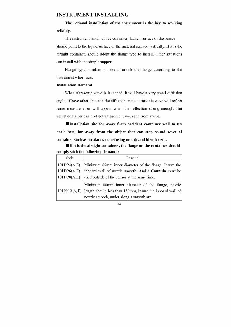
For HUL4(A,E), 101DP6(A,E), 101DP8(A,E) as follows instance
a Cannula must be used outside of the sensor.
1. At a container flange to install.
2. Install at the thicker floor slab hatch..
3. At raise edge of the container (pool) stomata
4. in a tube to install.
Narrate: When the sensor of measuring range 4m, 6m, 8m, their side face
closer comparatively to other object .this object come into surrounding more
to sensor ,or the area is too big to the face of sensor, the instrument maybe
become fake signal, So that the instrument can’t normal work. With
above-mentioned instance, please install cannula on the sensor as follows:
. At a container flange to install Install to a tube
At raise adge of the container (pool) stomata . Install at the thicker floor slab hatch
The instance of a Cannula must be used
14
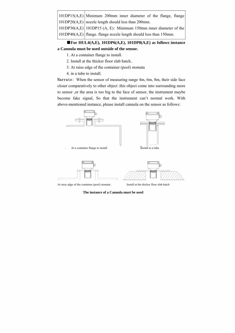
For 101DP15(A,E), 101DP20(A,E), 101DP30(A,E),
101DP40(A,E) : when they are installed at the flange on the container,
at the thicker floor slab hatch, at raise edge of the container(pool)
stomata , it needs that the highness or the thickness should less than the
length of the sensor. Showing as follows:
15
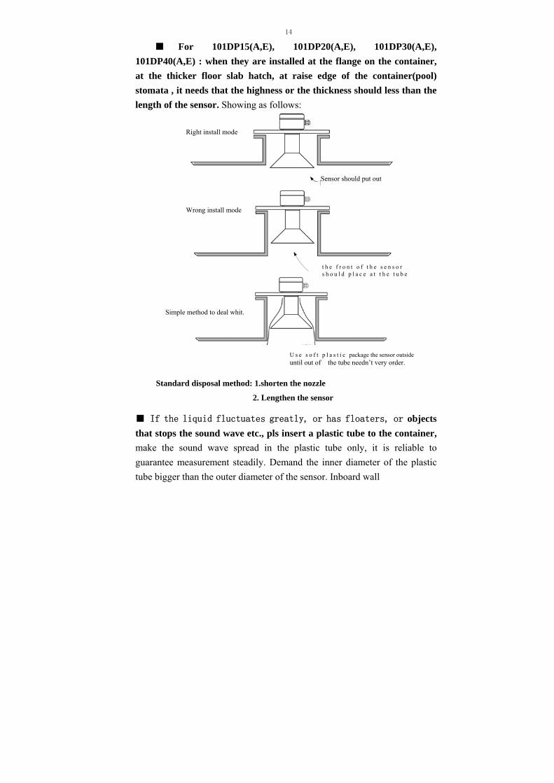
If the liquid fluctuates greatly, or has floaters, or objects
that stops the sound wave etc., pls insert a plastic tube to the container,
make the sound wave spread in the plastic tube only, it is reliable to
guarantee measurement steadily. Demand the inner diameter of the plastic
tube bigger than the outer diameter of the sensor. Inboard wall
U s e s o f t p l a s t i c package the sensor outside until out of the tube needn’t very order.
Simple method to deal whit.
Right install mode
Sensor should put out
Standard disposal method: 1.shorten the nozzle
2. Lengthen the sensor
t h e f r o n t o f t h e s e n s o r s h o u l d p l a c e a t t h e t u b e
Wrong install mode
15
Join the plastic tube to install position and angle, when level off measuring measure material location
must be smooth, equal straight and no seam, The plastic tube should be
straight, one hole should be open in top and bottom, so as to ensure that it is
the same to be in charge of the internal and external level Simultaneity, for
Measuring range 4m, 6m, 8m level meter, a Cannula must be used outside
of the sensor.
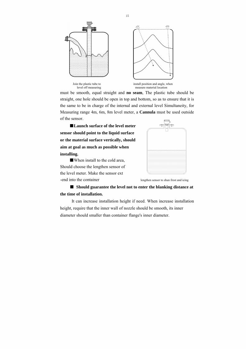
Launch surface of the level meter
sensor should point to the liquid surface
or the material surface vertically, should
aim at goal as much as possible when
installing.
When install to the cold area,
Should choose the lengthen sensor of
the level meter. Make the sensor ext
-end into the container lengthen sensor to shun frost and icing
Should guarantee the level not to enter the blanking distance at
the time of installation.
It can increase installation height if need. When increase installation
height, require that the inner wall of nozzle should be smooth, its inner
diameter should smaller than container flange's inner diameter.
16
When the flange type installed, it should be a plastic material
flange compounded for the sensor.
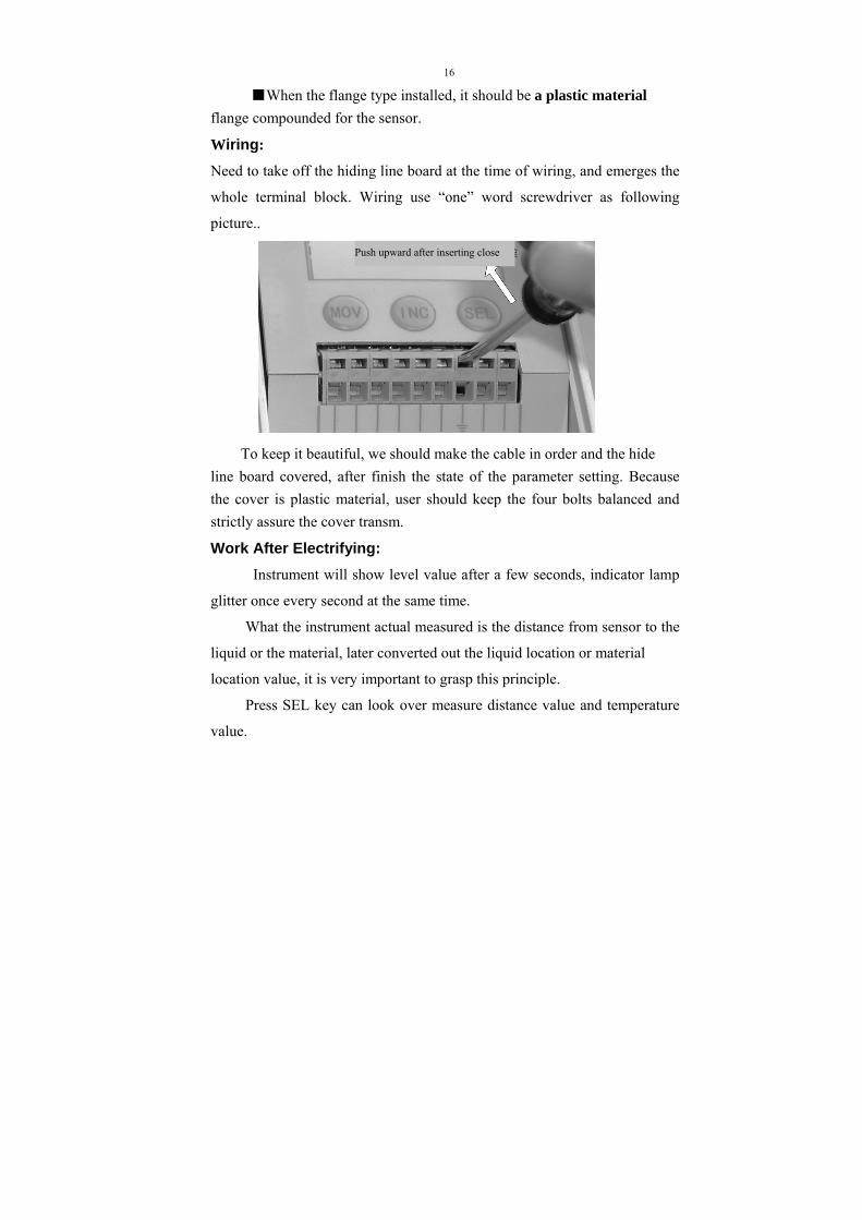
Wiring:
Need to take off the hiding line board at the time of wiring, and emerges the
whole terminal block. Wiring use “one” word screwdriver as following
picture..
To keep it beautiful, we should make the cable in order and the hide
line board covered, after finish the state of the parameter setting. Because
the cover is plastic material, user should keep the four bolts balanced and
strictly assure the cover transm.
Work After Electrifying:
Instrument will show level value after a few seconds, indicator lamp
glitter once every second at the same time.
What the instrument actual measured is the distance from sensor to the
liquid or the material, later converted out the liquid location or material
location value, it is very important to grasp this principle.
Press SEL key can look over measure distance value and temperature
value.
Push upward after inserting close
17
Press MOV and SEL keys at the same time can enter parameter setting
up state, after setting up installing height and measuring range, established
upper limit and lower limit according to the need, then pressed SEL key
once again. Then press MOV and SEL keys at the same time and return to
measure state. The instrument will show correct level value, will output the
correct current signal , the switch signal in the upper limit and lower limit.
If measurement is wrong, please refer to the next section that "Trouble
Deal With ".
Airproof Instrument
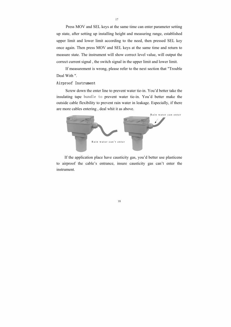
Screw down the enter line to prevent water tie-in. You’d better take the
insulating tape bundle to prevent water tie-in. You’d better make the
outside cable flexibility to prevent rain water in leakage. Especially, if there
are more cables entering , deal whit it as above.
If the application place have causticity gas, you’d better use plasticene
to airproof the cable’s entrance, insure causticity gas can’t enter the
instrument.
18
R a i n w a t e r c a n ’ t e n t e r
R a i n w a t e r c a n e n t e r
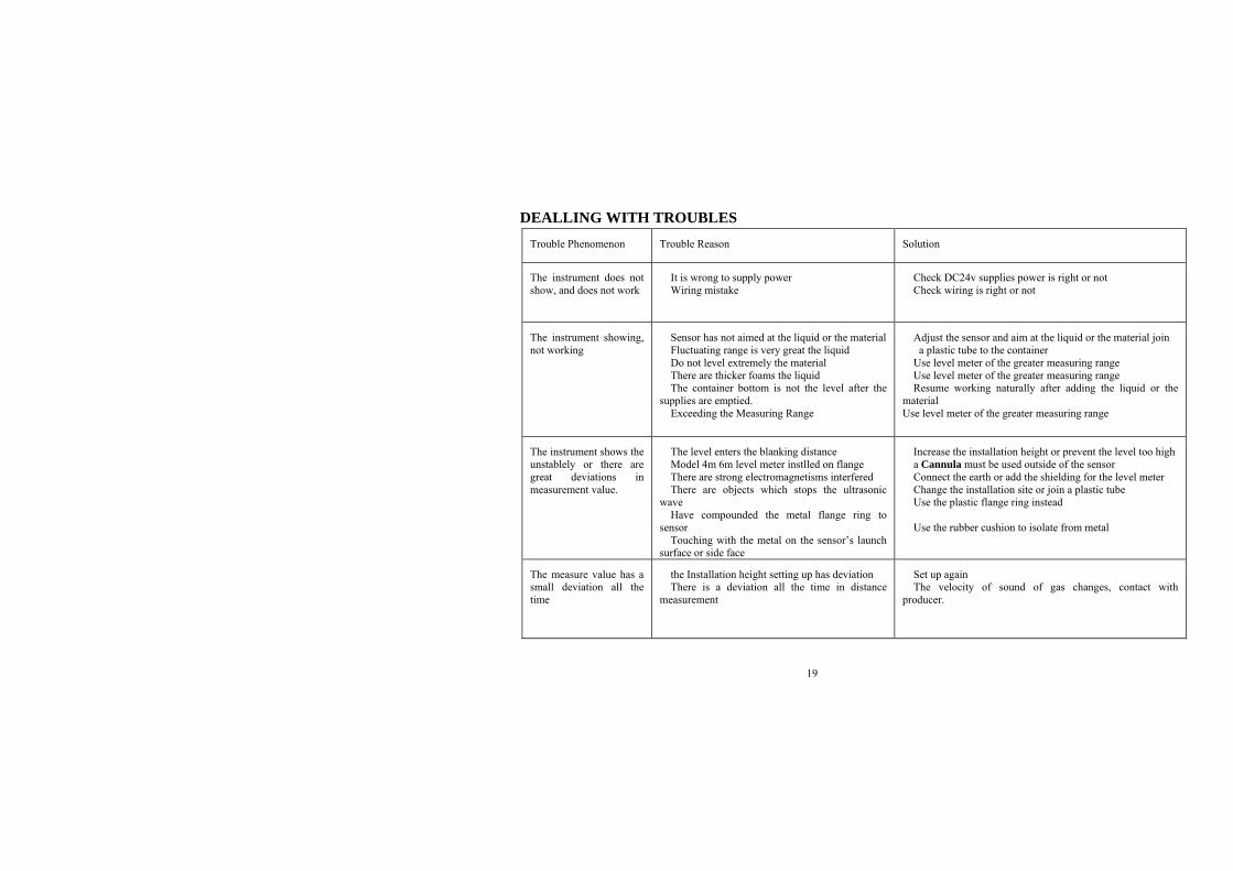
DEALLING WITH TROUBLES
Trouble Phenomenon Trouble Reason Solution
The instrument does not show, and does not work
It is wrong to supply power Wiring mistake
Check DC24v supplies power is right or not Check wiring is right or not
The instrument showing, not working
Sensor has not aimed at the liquid or the material Fluctuating range is very great the liquid Do not level extremely the material There are thicker foams the liquid The container bottom is not the level after the
supplies are emptied. Exceeding the Measuring Range
Adjust the sensor and aim at the liquid or the material join a plastic tube to the container Use level meter of the greater measuring range Use level meter of the greater measuring range Resume working naturally after adding the liquid or the
material Use level meter of the greater measuring range
The instrument shows the unstablely or there are great deviations in measurement value.
The level enters the blanking distance Model 4m 6m level meter instlled on flange There are strong electromagnetisms interfered There are objects which stops the ultrasonic
wave Have compounded the metal flange ring to
sensor Touching with the metal on the sensor’s launch
surface or side face
Increase the installation height or prevent the level too high a Cannula must be used outside of the sensor Connect the earth or add the shielding for the level meter Change the installation site or join a plastic tube Use the plastic flange ring instead Use the rubber cushion to isolate from metal
The measure value has a small deviation all the time
the Installation height setting up has deviation There is a deviation all the time in distance
measurement
Set up again The velocity of sound of gas changes, contact with
producer.
19